CN101932375A - Removal of contaminants from gas streams - Google Patents
Removal of contaminants from gas streamsDownload PDFInfo
- Publication number
- CN101932375A CN101932375ACN2008801259497ACN200880125949ACN101932375ACN 101932375 ACN101932375 ACN 101932375ACN 2008801259497 ACN2008801259497 ACN 2008801259497ACN 200880125949 ACN200880125949 ACN 200880125949ACN 101932375 ACN101932375 ACN 101932375A
- Authority
- CN
- China
- Prior art keywords
- regeneration
- sulfur
- sorbent
- gas stream
- adsorbent
- Prior art date
- Legal status (The legal status is an assumption and is not a legal conclusion. Google has not performed a legal analysis and makes no representation as to the accuracy of the status listed.)
- Granted
Links
Images
Classifications
- C—CHEMISTRY; METALLURGY
- C10—PETROLEUM, GAS OR COKE INDUSTRIES; TECHNICAL GASES CONTAINING CARBON MONOXIDE; FUELS; LUBRICANTS; PEAT
- C10L—FUELS NOT OTHERWISE PROVIDED FOR; NATURAL GAS; SYNTHETIC NATURAL GAS OBTAINED BY PROCESSES NOT COVERED BY SUBCLASSES C10G OR C10K; LIQUIFIED PETROLEUM GAS; USE OF ADDITIVES TO FUELS OR FIRES; FIRE-LIGHTERS
- C10L3/00—Gaseous fuels; Natural gas; Synthetic natural gas obtained by processes not covered by subclass C10G, C10K; Liquefied petroleum gas
- C10L3/06—Natural gas; Synthetic natural gas obtained by processes not covered by C10G, C10K3/02 or C10K3/04
- C10L3/10—Working-up natural gas or synthetic natural gas
- C10L3/101—Removal of contaminants
- C10L3/102—Removal of contaminants of acid contaminants
- C10L3/103—Sulfur containing contaminants
- B—PERFORMING OPERATIONS; TRANSPORTING
- B01—PHYSICAL OR CHEMICAL PROCESSES OR APPARATUS IN GENERAL
- B01J—CHEMICAL OR PHYSICAL PROCESSES, e.g. CATALYSIS OR COLLOID CHEMISTRY; THEIR RELEVANT APPARATUS
- B01J20/00—Solid sorbent compositions or filter aid compositions; Sorbents for chromatography; Processes for preparing, regenerating or reactivating thereof
- B01J20/02—Solid sorbent compositions or filter aid compositions; Sorbents for chromatography; Processes for preparing, regenerating or reactivating thereof comprising inorganic material
- B01J20/0203—Solid sorbent compositions or filter aid compositions; Sorbents for chromatography; Processes for preparing, regenerating or reactivating thereof comprising inorganic material comprising compounds of metals not provided for in B01J20/04
- B01J20/0225—Compounds of Fe, Ru, Os, Co, Rh, Ir, Ni, Pd, Pt
- B—PERFORMING OPERATIONS; TRANSPORTING
- B01—PHYSICAL OR CHEMICAL PROCESSES OR APPARATUS IN GENERAL
- B01J—CHEMICAL OR PHYSICAL PROCESSES, e.g. CATALYSIS OR COLLOID CHEMISTRY; THEIR RELEVANT APPARATUS
- B01J20/00—Solid sorbent compositions or filter aid compositions; Sorbents for chromatography; Processes for preparing, regenerating or reactivating thereof
- B01J20/02—Solid sorbent compositions or filter aid compositions; Sorbents for chromatography; Processes for preparing, regenerating or reactivating thereof comprising inorganic material
- B01J20/0203—Solid sorbent compositions or filter aid compositions; Sorbents for chromatography; Processes for preparing, regenerating or reactivating thereof comprising inorganic material comprising compounds of metals not provided for in B01J20/04
- B01J20/024—Compounds of Zn, Cd, Hg
- B01J20/0244—Compounds of Zn
- B—PERFORMING OPERATIONS; TRANSPORTING
- B01—PHYSICAL OR CHEMICAL PROCESSES OR APPARATUS IN GENERAL
- B01J—CHEMICAL OR PHYSICAL PROCESSES, e.g. CATALYSIS OR COLLOID CHEMISTRY; THEIR RELEVANT APPARATUS
- B01J20/00—Solid sorbent compositions or filter aid compositions; Sorbents for chromatography; Processes for preparing, regenerating or reactivating thereof
- B01J20/02—Solid sorbent compositions or filter aid compositions; Sorbents for chromatography; Processes for preparing, regenerating or reactivating thereof comprising inorganic material
- B01J20/06—Solid sorbent compositions or filter aid compositions; Sorbents for chromatography; Processes for preparing, regenerating or reactivating thereof comprising inorganic material comprising oxides or hydroxides of metals not provided for in group B01J20/04
- B—PERFORMING OPERATIONS; TRANSPORTING
- B01—PHYSICAL OR CHEMICAL PROCESSES OR APPARATUS IN GENERAL
- B01J—CHEMICAL OR PHYSICAL PROCESSES, e.g. CATALYSIS OR COLLOID CHEMISTRY; THEIR RELEVANT APPARATUS
- B01J20/00—Solid sorbent compositions or filter aid compositions; Sorbents for chromatography; Processes for preparing, regenerating or reactivating thereof
- B01J20/30—Processes for preparing, regenerating, or reactivating
- B01J20/34—Regenerating or reactivating
- B01J20/3433—Regenerating or reactivating of sorbents or filter aids other than those covered by B01J20/3408 - B01J20/3425
- B—PERFORMING OPERATIONS; TRANSPORTING
- B01—PHYSICAL OR CHEMICAL PROCESSES OR APPARATUS IN GENERAL
- B01J—CHEMICAL OR PHYSICAL PROCESSES, e.g. CATALYSIS OR COLLOID CHEMISTRY; THEIR RELEVANT APPARATUS
- B01J20/00—Solid sorbent compositions or filter aid compositions; Sorbents for chromatography; Processes for preparing, regenerating or reactivating thereof
- B01J20/30—Processes for preparing, regenerating, or reactivating
- B01J20/34—Regenerating or reactivating
- B01J20/345—Regenerating or reactivating using a particular desorbing compound or mixture
- B01J20/3458—Regenerating or reactivating using a particular desorbing compound or mixture in the gas phase
- C—CHEMISTRY; METALLURGY
- C10—PETROLEUM, GAS OR COKE INDUSTRIES; TECHNICAL GASES CONTAINING CARBON MONOXIDE; FUELS; LUBRICANTS; PEAT
- C10K—PURIFYING OR MODIFYING THE CHEMICAL COMPOSITION OF COMBUSTIBLE GASES CONTAINING CARBON MONOXIDE
- C10K1/00—Purifying combustible gases containing carbon monoxide
- C10K1/20—Purifying combustible gases containing carbon monoxide by treating with solids; Regenerating spent purifying masses
- C10K1/26—Regeneration of the purifying material contains also apparatus for the regeneration of the purifying material
- C—CHEMISTRY; METALLURGY
- C10—PETROLEUM, GAS OR COKE INDUSTRIES; TECHNICAL GASES CONTAINING CARBON MONOXIDE; FUELS; LUBRICANTS; PEAT
- C10L—FUELS NOT OTHERWISE PROVIDED FOR; NATURAL GAS; SYNTHETIC NATURAL GAS OBTAINED BY PROCESSES NOT COVERED BY SUBCLASSES C10G OR C10K; LIQUIFIED PETROLEUM GAS; USE OF ADDITIVES TO FUELS OR FIRES; FIRE-LIGHTERS
- C10L3/00—Gaseous fuels; Natural gas; Synthetic natural gas obtained by processes not covered by subclass C10G, C10K; Liquefied petroleum gas
- C10L3/06—Natural gas; Synthetic natural gas obtained by processes not covered by C10G, C10K3/02 or C10K3/04
- C10L3/10—Working-up natural gas or synthetic natural gas
- C10L3/101—Removal of contaminants
- C10L3/102—Removal of contaminants of acid contaminants
Landscapes
- Chemical & Material Sciences (AREA)
- Organic Chemistry (AREA)
- Chemical Kinetics & Catalysis (AREA)
- Analytical Chemistry (AREA)
- Oil, Petroleum & Natural Gas (AREA)
- Engineering & Computer Science (AREA)
- Inorganic Chemistry (AREA)
- General Chemical & Material Sciences (AREA)
- Combustion & Propulsion (AREA)
- Solid-Sorbent Or Filter-Aiding Compositions (AREA)
- Separation Of Gases By Adsorption (AREA)
- Gas Separation By Absorption (AREA)
Abstract
Translated fromChinese
Description
Translated fromChinese发明背景Background of the invention
1.发明领域1. Field of invention
本发明整体上涉及从气流中除去污染物。另一方面,本发明涉及通过与可再生吸附剂接触来从气流中除去一种或多种污染物的方法。The present invention generally relates to the removal of pollutants from gas streams. In another aspect, the invention relates to a method for removing one or more pollutants from a gas stream by contacting with a regenerable sorbent.
2.现有技术描述2. Description of prior art
近年来,对天然气和其它气相燃料的需求显著增长。同时,对某些组分(例如硫类、酸性气和其它与环境相关的化合物)的容许含量执行更严格的规章,以促使燃料气体制造商开发经济的制造合格气体产品的方法。Demand for natural gas and other gas-phase fuels has grown significantly in recent years. At the same time, stricter regulations are being enforced on the allowable levels of certain components, such as sulfur, acid gases, and other environmentally relevant compounds, to prompt fuel gas manufacturers to develop economical methods of producing compliant gas products.
处理气流以除去不合意组分的一种已知方法是使该气流与物理或化学溶剂接触。化学溶剂的实例包括胺,如甲基二乙醇胺(MDEA)和二乙醇胺(DEA)。通常,化学溶剂的选择性有问题。例如,尽管胺能从气流中有效除去硫化氢(H2S),但胺通常不能吸收其它不合意的含硫化合物,例如硫化羰(COS)。因此,在该气流可用作燃料之前必须进行附加工艺步骤(例如COS水解)。除了除去H2S外,大多数胺还除去二氧化碳,这对后继废气设施施加不必要的加工负荷。此外,利用化学溶剂的大多数方法要求引入的气流的大规模冷却并通常使用大量蒸汽从该溶剂中除去吸收的污染物,这使这些方法能量密集。基于物理溶剂的方法也非常能量密集,并通常需要高运行压力和/或低运行温度。One known method of treating a gas stream to remove undesirable components is to contact the gas stream with a physical or chemical solvent. Examples of chemical solvents include amines such as methyldiethanolamine (MDEA) and diethanolamine (DEA). Often, the selectivity of chemical solvents is problematic. For example, while amines are effective at removing hydrogen sulfide (H2S ) from gas streams, amines are generally incapable of absorbing other undesirable sulfur-containing compounds, such as carbonyl sulfide (COS). Therefore, additional process steps (such as COS hydrolysis) must be performed before this gas stream can be used as fuel. In addition to removingH2S , most amines also remove carbon dioxide, which places an unnecessary process load on subsequent off-gas facilities. Furthermore, most methods utilizing chemical solvents require extensive cooling of the incoming gas stream and typically use large amounts of steam to remove absorbed contaminants from the solvent, making these methods energy intensive. Physical solvent based methods are also very energy intensive and typically require high operating pressures and/or low operating temperatures.
因此,需要用于从气流中除去污染物的经济方法。Therefore, there is a need for economical methods for removing pollutants from gas streams.
发明概述Summary of the invention
在本发明的一个实施方案中,提供一种方法,包括:(a)使含硫气流在吸附区中与初始吸附剂接触,由此产生脱硫产物流和载硫吸附剂,其中该初始吸附剂包含Zn和促进剂金属;和(b)使至少一部分该载硫吸附剂在再生区中在再生条件下与再生气流接触,由此产生再生的吸附剂和废气流,其中步骤(b)的接触包括将该再生气以大约100至大约100,000h-1的初始标准气时空速(SGHSV)引入再生区,其中步骤(b)的接触包括将该再生气的SGHSV提高至比初始SGHSV高至少1,000h-1的最终SGHSV。In one embodiment of the present invention there is provided a process comprising: (a) contacting a sulfur-containing gas stream with an initial adsorbent in an adsorption zone, thereby producing a desulfurized product stream and a sulfur-laden adsorbent, wherein the initial adsorbent comprising Zn and a promoter metal; and (b) contacting at least a portion of the sulfur-laden sorbent with a regeneration gas stream under regeneration conditions in a regeneration zone, thereby producing a regenerated sorbent and a waste gas stream, wherein the contacting of step (b) comprising introducing the regeneration gas into the regeneration zone at an initial standard gas hourly space velocity (SGHSV) of about 100 to about 100,000h , wherein the contacting of step (b) includes increasing the SGHSV of the regeneration gas to at least 1,000 h higher than the initial SGHSV-1 for final SGHSV.
在本发明的另一实施方案中,提供一种方法,包括:(a)将原始气流引入吸附区,其中该原始气流包含大约10至大约75体积%一氧化碳(CO)、大约8至大约50体积%氢气(H2)、大约4至大约40体积%水(H2O)和大约0.001至大约5体积%硫化氢(H2S);(b)使至少一部分该原始气流在该吸附区中与初始吸附剂接触,由此产生产物气流和载硫吸附剂,其中该初始吸附剂包含Zn和促进剂金属;(c)干燥至少一部分该载硫吸附剂,由此产生干燥的载硫吸附剂;和(d)在再生区中在再生条件下再生至少一部分该干燥的载硫吸附剂,由此产生再生的吸附剂和废气流,其中该再生的吸附剂包含少于大约20重量%的在步骤(d)的再生过程中形成的吸附剂破坏化合物。In another embodiment of the present invention, a method is provided, comprising: (a) introducing a raw gas stream into an adsorption zone, wherein the raw gas stream comprises from about 10 to about 75 volume percent carbon monoxide (CO), from about 8 to about 50 volume percent % hydrogen (H2 ), about 4 to about 40% by volume water (H2 O) and about 0.001 to about 5% by volume hydrogen sulfide (H2 S); (b) having at least a portion of the original gas stream in the adsorption zone contacting an initial sorbent, thereby producing a product gas stream and a sulfur-laden sorbent, wherein the initial sorbent comprises Zn and a promoter metal; (c) drying at least a portion of the sulfur-laden sorbent, thereby producing a dried sulfur-laden sorbent and (d) regenerating at least a portion of the dried sulfur-laden sorbent under regeneration conditions in a regeneration zone, thereby producing a regenerated sorbent and a waste stream, wherein the regenerated sorbent contains less than about 20% by weight of Sorbent destroying compounds formed during the regeneration of step (d).
在本发明的再一实施方案中,提供一种方法,包括:(a)在气化区中气化含碳材料,由此产生原始气流,其中该原始气流包含大约10至大约75体积%一氧化碳(CO)、大约8至大约50体积%氢气(H2)、大约4至大约40体积%水(H2O)、大约0.001至大约5体积%含硫化合物和百万分之大约50至大约2,000体积份(ppmv)的盐酸(HCl);(b)将至少一部分该原始气流引入吸附区,其中该吸附区含有初始吸附剂,其中该初始吸附剂包含Zn、膨胀珍珠岩和促进剂金属,其中至少一部分该初始吸附剂包含以式MZZn(1-Z)Al2O4为特征的置换固溶体(substitutional solid solution)和以式MAZnB为特征的置换金属固溶体(substitutional solid metal solution),其中M是促进剂金属组分且A、B和Z为大约0.01至大约0.99;(c)在该吸附区中用该初始吸附剂从该原始气流中吸附至少一部分该含硫化合物,由此产生载硫吸附剂和产物气流,其中该吸附在大约225至大约550℃的温度和大约250至大约575psig的压力下进行,其中该载硫吸附剂具有大约1至大约27重量%的硫载量,其中该产物气流包含少于50ppmv的含硫材料和少于20ppmv的HCl;(d)在干燥区中干燥至少一部分该载硫吸附剂,由此产生干燥的载硫吸附剂;(e)在再生区中通过与再生气在再生条件下接触来再生至少一部分该干燥的载硫吸附剂,由此产生再生的吸附剂和含SO2的废气,其中该再生气具有大约1,000至大约80,000h-1的初始标准气时空速(SGHSV),其中用大约300至大约600℃的初始温度进行该再生;(f)将至少一部分该再生的吸附剂送回吸附区,其中送回吸附区的该再生的吸附剂包含以式MXZnYO为特征的置换金属氧化物固溶体(substitutional solid metal oxide solution),其中M是促进剂金属组分且X和Y为大约0.01至大约0.99,其中该再生的吸附剂具有小于6重量%的硫载量,其中该再生的吸附剂包含少于20重量%的在步骤(e)的再生过程中产生的吸附剂破坏化合物;和(g)将至少一部分该含SO2的废气流送回克劳斯装置。In yet another embodiment of the present invention, a method is provided comprising: (a) gasifying carbonaceous material in a gasification zone, thereby producing a raw gas stream, wherein the raw gas stream comprises from about 10 to about 75 volume percent carbon monoxide (CO), about 8 to about 50 volume percent hydrogen (H2 ), about 4 to about 40 volume percent water (H2 O), about 0.001 to about 5 volume percent sulfur compounds, and about 50 to about 2,000 parts by volume (ppmv) of hydrochloric acid (HCl); (b) introducing at least a portion of the raw gas stream into an adsorption zone, wherein the adsorption zone contains an initial adsorbent, wherein the initial adsorbent comprises Zn, expanded perlite, and a promoter metal, wherein at least a portion of the initial adsorbent comprises a substitutional solid solution characterized by the formula MZ Zn(1-Z) Al2 O4 and a substitutional solid metal solution characterized by the formula MA ZnB ), wherein M is a promoter metal component and A, B, and Z are from about 0.01 to about 0.99; (c) adsorbing at least a portion of the sulfur-containing compound from the raw gas stream with the initial adsorbent in the adsorption zone, by This produces a sulfur-laden sorbent having a sulfur loading of about 1 to about 27% by weight and a product gas stream, wherein the adsorption is performed at a temperature of about 225 to about 550°C and a pressure of about 250 to about 575 psig. amount, wherein the product gas stream comprises less than 50 ppmv of sulfur-containing material and less than 20 ppmv of HCl; (d) drying at least a portion of the sulfur-laden sorbent in a drying zone, thereby producing a dry sulfur-laden sorbent; (e) At least a portion of the dried sulfur-laden sorbent is regenerated in a regeneration zone by contacting with a regeneration gas under regeneration conditions, thereby producing a regenerated sorbent and aSO2- containing waste gas, wherein the regeneration gas has a concentration of about 1,000 to about 80,000 h-1 initial standard gas hourly space velocity (SGHSV), wherein the regeneration is performed with an initial temperature of about 300 to about 600° C.; (f) returning at least a portion of the regenerated adsorbent to the adsorption zone, wherein the The regenerated sorbent comprises a substitutional solid metal oxide solution characterized by the formula MX ZnY O, wherein M is the promoter metal component and X and Y are from about 0.01 to about 0.99, wherein the regenerated The sorbent has a sulfur loading of less than 6% by weight, wherein the regenerated sorbent comprises less than 20% by weight of sorbent-destroying compounds produced during the regeneration of step (e); and (g) at least a portion of the The exhaust stream containingSO2 is sent back to the Claus unit.
附图简述Brief description of the drawings
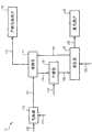
图1是根据本发明的一个实施方案的污染物去除系统的示意图。Figure 1 is a schematic diagram of a pollutant removal system according to one embodiment of the present invention.
发明详述Detailed description of the invention
参照图1,污染物去除系统10图解为大致包含气体源12、吸附区14、产物气体用户16、干燥区18、再生区20和废气用户22。一般而言,可以使离开气体源12的原始气流在吸附区14中与吸附剂接触,由此从该气流中除去一种或多种污染物。离开吸附区14的所得脱污染物的产物气流可以送往产物气体用户16,而至少一部分该载污染物的吸附剂可以在通过在再生区20中与再生气接触来再生之前在干燥区18中干燥。离开再生区20的所得废气流可以送往废气用户22,而至少一部分该再生的吸附剂可随后送回吸附区14以随后再利用。在一个实施方案中,吸附、干燥和再生区14、18、20中的至少一个可包含在相同工艺器内。在另一实施方案中,吸附、干燥和再生区14、18、20中的至少一个可包含在两个或更多个独立的工艺器中。此外,图1中所示的污染物去除系统10可以以连续、半连续、半分批或分批模式运行。下面更详细描述污染物去除系统10的运行。Referring to FIG. 1 , a
气体源12可包含能够产生气流的任何来源或系统。一般而言,由气体源12产生的原始气流可以在标准条件下具有大于大约0.8,大于大约0.9,或大于0.95的蒸气分数。在一个实施方案中,来自气体源12的该原始气流可包含少于大约1体积%,少于大约0.5体积%,少于0.05体积%,或少于百万分之500体积份(ppmv)的C6+烃材料。例如,气体源12可包括天然气井、炼油厂或化工厂工艺流或任何其它合适的来源。
在一个实施方案中,气体源12可包括可经由固体基含碳材料,例如煤或石油焦的气化产生原始气流的气化系统。通常,该固体含碳材料可通过与包含蒸汽、氧气、空气、氢气、二氧化碳或其任何组合的气化流接触来气化。在一个实施方案中,导管100中的固体含碳材料的浆料可以通过与经由导管110进入气体源12的含氧流在大约530至大约1950℃,大约810至大约1650℃,或950至1510℃的温度和大约150至大约800磅/平方英寸,表压(psig),大约250至大约700psig,或300至600psig的压力下接触来气化。In one embodiment,
经由导管112离开气体源12的原始气流可包含一种或多种下列化合物:一氧化碳(CO)、二氧化碳(CO2)、氢气(H2)、水(H2O)、丙烷和更轻的烃(C3+)、氮气(N2)等。另外,该原始气流可包含一种或多种不合意的组分(即污染物),它们应在使用该原始气流作为燃料之前除去。硫化合物,例如,硫化氢(H2S)、硫化羰(COS)、二硫化碳(CS2)和甚至有机硫化合物,如硫醇和各种噻吩化合物是该原始气流中存在的常见污染物的一些实例。该原始气流中常见的污染物的其它实例可包括,但不限于氨(NH3)、盐酸(HCl)和氰化氢(HCN)。The raw gas stream exiting
下表1概括根据本发明的一个实施方案在导管112中的原始气流的组成。Table 1 below summarizes the composition of the raw gas stream in

如图1中所示,在导管112中离开气体源12的至少一部分原始气流可送入吸附区14,在此可以使该流与吸附剂接触以从引入的气流中除去至少一部分至少一种污染物。在一个实施方案中,该原始气流在进入吸附区14之前不冷却并可具有在离开气体源12的原始气流的温度的大约200℃,大约100℃,或50℃内的温度。通常,进入吸附区14的原始气流可具有大约150至大约700℃,大约250至大约600℃,或350至450℃的温度和大约100至大约750psig,大约250至大约600psig,或350至450psig的压力。As shown in FIG. 1 , at least a portion of the raw gas stream exiting
一般而言,吸附区14中所用的吸附剂可以是具有充足的污染物去除能力的任何充分可再生的氧化锌基吸附剂组合物。尽管下文描述了其从引入的气流中除去硫污染物的能力,但应该理解的是,本发明的吸附剂也具有除去一种或多种其它污染物,例如一种或多种上列污染物的显著能力。In general, the sorbent used in
在本发明的一个实施方案中,吸附区14中所用的吸附剂可包含锌和促进剂金属组分。该促进剂金属组分可包含一种或多种选自镍、钴、铁、锰、钨、银、金、铜、铂、锌、锡、钌、钼、锑、钒、铱、铬、钯及其混合物的促进剂金属。在一个实施方案中,至少一部分该促进剂金属组分以还原价的状态存在。可以通过使吸附剂在吸附区14内和/或在引入吸附区14之前与含氢流接触来实现促进剂金属组分的价态还原。In one embodiment of the present invention, the adsorbent used in
在本发明的一个实施方案中,该还原价的促进剂金属组分可以包含以式:MAZnB为特征的置换金属固溶体,由其构成或基本由其构成,其中M是促进剂金属且A和B各自是大约0.01至大约0.99的数值。在该置换金属固溶体的上式中,A可以为大约0.70至大约0.98,或0.85至0.95,B可以为大约0.03至大约0.30,或0.05至0.15。在一个实施方案中,A+B=1。In one embodiment of the invention, the reducing valent promoter metal component may comprise, consist of, or consist essentially of a solid solution of a substitutional metal characterized by the formula: MA ZnB , wherein M is a promoter metal and A and B are each a value of about 0.01 to about 0.99. In the above formula for the replacement metal solid solution, A may be about 0.70 to about 0.98, or 0.85 to 0.95, and B may be about 0.03 to about 0.30, or 0.05 to 0.15. In one embodiment, A+B=1.
置换固溶体是通过在晶体结构中用溶质金属直接置换溶剂金属原子而形成的合金的子集。例如,认为,该置换金属固溶体MAZnB通过溶质锌金属原子置换溶剂促进剂金属原子来形成。存在有利于形成置换金属固溶体的三个基本标准:(1)两种元素的原子半径在彼此的15%内;(2)两种纯相的晶体结构相同;和(3)两种组分的电负性类似。本文所述的吸附剂中所用的促进剂金属(元素金属或金属氧化物形式)和锌(元素金属或金属氧化物形式)通常符合上述三个标准中的至少两个。例如,当该促进剂金属是镍时,符合第一和第三标准,但不符合第二标准。镍和锌金属原子半径在彼此的10%内且电负性类似。但是,氧化镍(NiO)优选形成立方晶体结构,而氧化锌(ZnO)优选形成六方晶体结构。镍锌固溶体保留氧化镍的立方结构。迫使氧化锌留在该立方结构中提高了该相的能量,这限制可溶解在该氧化镍结构中的锌的量。这种化学计量控制本身显微表现在还原过程中形成的92∶8镍锌固溶体(Ni0.92Zn0.08)中和显微表现在吸附剂的可反复再生性中。Substitutional solid solutions are a subset of alloys formed by the direct substitution of solute metal atoms in the crystal structure. For example, it is believed that the replacement metal solid solution MA ZnB is formed by the replacement of solvent promoter metal atoms by solute zinc metal atoms. There are three basic criteria that favor the formation of substitutional metal solid solutions: (1) the atomic radii of the two elements are within 15% of each other; (2) the crystal structures of the two pure phases are identical; and (3) the Electronegativity is similar. Promoter metals (in elemental metal or metal oxide form) and zinc (in elemental metal or metal oxide form) used in the sorbents described herein typically meet at least two of the above three criteria. For example, when the promoter metal is nickel, the first and third criteria are met, but the second criterion is not met. Nickel and zinc metal atomic radii are within 10% of each other and have similar electronegativity. However, nickel oxide (NiO) preferably forms a cubic crystal structure, while zinc oxide (ZnO) preferably forms a hexagonal crystal structure. The nickel-zinc solid solution retains the cubic structure of nickel oxide. Forcing the zinc oxide to remain in the cubic structure increases the energy of the phase, which limits the amount of zinc that can be dissolved in the nickel oxide structure. This stoichiometric control manifests itself microscopically in the 92:8 nickel-zinc solid solution (Ni0.92 Zn0.08 ) formed during the reduction process and microscopically in the reproducibility of the adsorbent.
除了锌和促进剂金属外,吸附区14中所用的吸附剂可进一步包含孔隙增强剂(PE)和铝酸盐。该铝酸盐可以包括以式:MZZn(1-Z)Al2O4为特征的促进剂金属-锌铝酸盐置换固溶体,其中M是促进剂金属且Z为0.01至0.99。该孔隙增强剂在使用时可以是最终提高该吸附剂的大孔性的任何化合物。在一个实施方案中,该孔隙增强剂可包含珍珠岩。适用在吸附区14中的吸附剂和这些吸附剂的制造方法的实例详细描述在美国专利Nos.6,429,170和7,241,929中,它们的整个公开内容经此引用并入本文。In addition to zinc and promoter metals, the adsorbent used in the
下表2提供根据本发明的一个实施方案在吸附区14中使用的吸附剂的组成,其中在将吸附剂引入吸附区14之前进行吸附剂的还原。Table 2 below provides the composition of the adsorbent used in the

在引入吸附区14之前不还原吸附剂的另一实施方案中,该促进剂金属组分可包含以式MXZnYO为特征的置换金属氧化物固溶体,其中M是促进剂金属且X和Y为大约0.01至大约0.99。在一个实施方案中,X可以是大约0.5至大约0.9,大约0.6至大约0.8,或0.65至0.75,Y可以是大约0.10至大约0.5,大约0.2至大约0.4,或0.25至0.35。一般而言,X+Y=1。In another embodiment where the sorbent is not reduced prior to introduction into
下表3提供根据在引入吸附区14之前不还原吸附剂的实施方案在吸附区14中使用的未还原的吸附剂的组成。Table 3 below provides the composition of the unreduced sorbent used in

如上所述,当使未还原的吸附剂组合物在吸附区14中与含氢的化合物接触时,可以在吸附区14中发生吸附剂的还原。因此,当在吸附区14中发生吸附剂还原时,在吸附区14中与原始气流接触的初始吸附剂可以是还原的吸附剂(表2)和未还原的吸附剂(表3)的混合物。As noted above, reduction of the sorbent may occur in the
一般而言,引入的原始气流可以在吸附区14中在大约150至大约650℃,大约225至大约550℃,或325至475℃的温度和大约100至大约750psig,大约250至575psig,或350至450psig的压力下接触初始吸附剂。该原始气流中的至少一部分含硫化合物(和/或其它污染物)可以被吸附剂吸附,由此产生脱硫产物气流和载硫吸附剂。在一个实施方案中,吸附区14的除硫效率可以大于大约85%,大于大约90%,大于大约95%,大于大约98%,或大于99%。Generally, the raw gas stream introduced can be in the
如图1中所示,至少一部分该脱除污染物的产物气流可经由导管114离开吸附区14。在一个实施方案中,该产物气流可包含少于大约50,少于大约20,少于大约10,少于大约5,或少于1ppmv H2S。此外,该产物气流可包含少于大约20,少于大约10,少于大约5,或少于2ppmv的HCl和/或COS。这不同于传统的除硫吸附剂,其通常不能有效地与其它污染物如HCl同时除去含硫化合物如H2S和COS。As shown in FIG. 1 , at least a portion of the decontaminated product gas stream may exit
如图1中所示,该脱除污染物的产物气流可随后送往产物气体用户16。产物气体用户16可包括脱除污染物的产物气流的任何工业、商业或住宅应用或用途。在一个实施方案中,产物气体用户16可包括位于用于共同产生蒸汽和电力的设施中的工业燃气轮机。This decontaminated product gas stream may then be sent to a
如图1中所示,从吸附区14中排出的至少一部分该载硫吸附剂可经由管道116送往干燥区18。在一个实施方案中,该载硫吸附剂可具有大约1至大约27,大约3至大约26,大约5至大约25,或10至20重量%的硫载量。在干燥区18中,至少一部分该载硫吸附剂可通过使导管118中的具有大约100至大约550℃,大约150至大约500℃,或200至475℃的温度的惰性气体吹扫流流过该吸附剂至少大约15分钟,或大约30分钟至大约100小时,大约45分钟至大约36小时,或1小时至12小时来干燥。所得干燥的载硫吸附剂可随后如图1中所示经由导管120送往再生区20。As shown in FIG. 1 , at least a portion of the sulfur-laden sorbent withdrawn from
再生区20可以使用能够通过在吸附剂再生条件下与再生气流接触来从该载硫吸附剂中除去至少一部分硫(或其它吸附的污染物)的再生法。在一个实施方案中,经由导管122进入再生区20的再生气流可包含含氧气流,例如空气(例如大约21体积%氧)。在另一实施方案中,导管120中的再生气流可以是包含至少大约50,至少大约75,至少大约85,或至少90体积%氧的富氧气流。在再一实施方案中,该再生气流可包含基本纯的氧流。
根据本发明的一个实施方案,再生区20中所用的再生法可以是逐步再生法。一般而言,逐步再生法包括在两次或更多次递增调节(即步骤)中将至少一个再生变量从初始值调节至最终值。可调节的再生变量的实例可包括,但不限于,温度、压力和再生气流速。在一个实施方案中,再生区20中的温度可以在可以为大约250至大约650℃,大约300至大约600℃,或350至550℃的初始温度以上提高至少大约75℃,至少大约100℃,或至少150℃的总量。在另一实施方案中,可以调节再生气流速以使与吸附剂接触的再生气的标准气时空速(SGHSV)在可以为大约100至大约100,000h-1,大约1,000至大约80,000h-1,或10,000至50,000h-1的初始SGHSV值以上提高至少大约1,000,至少大约2,500,至少大约5,000,或至少10,000气体体积/吸附剂体积/小时(v/v/h或h-1)的总量。According to one embodiment of the present invention, the regeneration method used in
在一个实施方案中,递增调节幅度(即递增步长)可以为所需总变化量值(即最终和初始值之间的差值)的大约2至大约50,大约5至大约40,或10至30%。例如,如果需要大约150℃的总温度变化,递增步长可以为大约3至大约75℃,大约7.5至大约60℃,或15至45℃。在另一实施方案中,递增步长的量值可以为初始变量值的量值的大约2至大约50,大约5至大约40,或10至30%。例如,如果初始再生温度为250℃,则递增步长可以为大约5至大约125℃,大约12.5至大约100℃,或25至75℃。一般而言,连续的递增步骤可具有相同的递增步长,或一个或多个递增步长可大于或小于在前或后继步骤的递增步长。In one embodiment, the incremental adjustment (i.e., incremental step size) can be from about 2 to about 50, from about 5 to about 40, or 10 times the desired total change magnitude (i.e., the difference between the final and initial values). to 30%. For example, if a total temperature change of about 150°C is desired, the incremental step size may be from about 3 to about 75°C, from about 7.5 to about 60°C, or from 15 to 45°C. In another embodiment, the magnitude of the incremental step may be from about 2 to about 50, from about 5 to about 40, or from 10 to 30 percent of the magnitude of the initial variable value. For example, if the initial regeneration temperature is 250°C, the incremental step size may be from about 5 to about 125°C, from about 12.5 to about 100°C, or from 25 to 75°C. In general, successive incremental steps may have the same incremental step size, or one or more incremental steps may be larger or smaller than the incremental step size of a preceding or subsequent step.
在一个实施方案中,可以以预定时间间隔进行再生变量的后继调节。例如,可以在大约1分钟至大约45分钟,大约2分钟至大约30分钟,或5至20分钟的时间间隔后进行调节。在另一实施方案中,可以基于一个或多个“指示”变量的值进行调节。指示变量是为测定吸附剂再生进程而监测的该系统中的变量。指示变量的实例可包括,但不限于,吸附剂碳或硫载量、再生吸附剂床温度、再生区温度状况(即放热)、和废气流组成。在一个实施方案中,监测废气流中的二氧化硫(SO2)浓度以确定何时递增调节再生气的流速和/或再生温度。In one embodiment, subsequent adjustments of the regeneration variable may be made at predetermined time intervals. For example, adjustments may be made after a time interval of about 1 minute to about 45 minutes, about 2 minutes to about 30 minutes, or 5 to 20 minutes. In another embodiment, adjustments may be made based on the value of one or more "indicator" variables. Indicator variables are variables in the system that are monitored to determine the progress of sorbent regeneration. Examples of indicator variables may include, but are not limited to, adsorbent carbon or sulfur loading, regenerated adsorbent bed temperature, regeneration zone temperature profile (ie, heat release), and off-gas stream composition. In one embodiment, the sulfur dioxide (SO2 ) concentration in the exhaust gas stream is monitored to determine when to incrementally adjust the regeneration gas flow rate and/or regeneration temperature.
可以在再生区20中进行再生法直至达到至少一个再生终点。在一个实施方案中,该再生终点可以是达到一个或多个受调节的再生变量的所需值。例如,可以进行再生法直至温度达到大约300至大约800℃,大约350至大约750℃,或400至700℃的最终值,或SGHSV达到大约1,100至大约110,000h-1,大约5,000至大约85,000h-1,或25,000至60,000h-1的最终值。在另一实施方案中,可以在预定的变量调节次数后结束再生法。例如,该再生法可以进行足够长的时间以便作出至少1次,或大约2至大约8次,或3至5次递增调节。在再一实施方案中,可以进行再生法直至达到所选指示变量的最终值。例如,可以进行再生法直至离开再生区20的废气中的SO2浓度降至小于大约1体积%,小于大约0.5体积%,小于大约0.1体积%,或小于500ppmv的值。不论所选特定终点如何,该再生法的总时长可以小于大约100小时,或大约30分钟至大约48小时,大约45分钟至大约24小时,或1.5至12.5小时。The regeneration process may be performed in the
在一个实施方案中,上述再生法可具有至少大约75%,至少大约85%,至少大约90%,至少大约95%,至少大约98%,或至少99%的再生效率。该再生的吸附剂可具有小于大约10重量%,或大约0.05至大约6重量%,或0.1至4重量%的硫载量。In one embodiment, the regeneration method described above may have a regeneration efficiency of at least about 75%, at least about 85%, at least about 90%, at least about 95%, at least about 98%, or at least 99%. The regenerated sorbent can have a sulfur loading of less than about 10 wt%, or about 0.05 to about 6 wt%, or 0.1 to 4 wt%.
一般而言,至少一部分上述吸附剂的再生可导致形成一种或多种吸附剂破坏化合物。吸附剂破坏化合物可以是吸附到吸附剂中或吸附剂上的不利地影响该吸附剂在吸附区14中从引入的气流中吸附硫的能力的任何化合物。吸附剂破坏化合物的实例可以包括,但不限于,含氧硫酸锌和硅酸锌。在本发明的一个实施方案中,在再生区20中经过上述再生法的再生的吸附剂可包含与经过传统再生法的传统吸附剂相比少于预计量的吸附剂破坏化合物。例如,经由导管124离开再生区的再生的吸附剂可包含少于大约20重量%的吸附剂破坏化合物,或0至大约15重量%,或0至大约10重量%,或0至5重量%的吸附剂破坏化合物。In general, regeneration of at least a portion of the aforementioned sorbents can result in the formation of one or more sorbent-destroying compounds. A sorbent-destroying compound may be any compound that adsorbs into or onto a sorbent that adversely affects the sorbent's ability to sorb sulfur from an incoming gas stream in
如图1中所示,导管124中的至少一部分该再生的吸附剂可随后送回吸附区14。如上所述,在一个实施方案中,至少一部分该再生的吸附剂在引入吸附区之前不经过还原步骤。在这种实施方案中,引入吸附区14的再生但未还原的吸附剂可包含含有以式MXZnYO为特征的置换金属氧化物固溶体(例如见上表3)的未还原的促进剂金属组分。As shown in FIG. 1 , at least a portion of the regenerated sorbent in
再参照图1,经由导管126离开再生区20的废气流可随后送往废气用户22。废气用户22可包括能够加工该废气流的任何装置,例如克劳斯硫加工装置。在一个实施方案中,经由导管126离开再生区20的废气流可包含至少大约5,至少大约10,至少大约20,或至少25体积%SO2。在一个实施方案中,该废气流包含比经由导管112进入吸附区14的原始气流中少的H2S。在另一实施方案中,废气流可基本不含H2S。Referring again to FIG. 1 , the exhaust gas stream exiting
下列实施例旨在例证本发明的一个实施方案以教导本领域普通技术人员利用本发明,其不是要以任何方式限制本发明的范围。The following examples are intended to illustrate one embodiment of the present invention in order to teach one of ordinary skill in the art to utilize the present invention, and are not intended to limit the scope of the present invention in any way.
实施例Example
将未还原的Zn-促进剂金属吸附剂(可购自Sud-Chemie Inc.of Louisville,Kentucky的SZorbTM Generation IV吸附剂)压碎和筛分以获得100+/200-筛目大小粒子。将15克碎吸附剂与45克刚铝石合并,并将所得混合物装入固定床--下流式反应容器。使原始气流--其组成概括在下表4中--通过该反应容器,并在420℃的温度和408psig的压力下与吸附剂混合物接触。Unreduced Zn-promoter metal sorbent (available as SZorb™ Generation IV sorbent from Sud-Chemie Inc. of Louisville, Kentucky) was crushed and sieved to obtain 100+/200-mesh size particles. 15 grams of crushed adsorbent was combined with 45 grams of alundite and the resulting mixture was charged to a fixed bed - downflow reaction vessel. The raw gas stream, the composition of which is summarized in Table 4 below, was passed through the reaction vessel and contacted with the adsorbent mixture at a temperature of 420°C and a pressure of 408 psig.
使用在线硫分析器(型号902D2,可获自Galvanic Applied Sciences USA,Inc.of Lowell,Massachusetts)连续监测离开反应容器的产物气流中硫化合物(即H2S和COS)的浓度,同时用在线质谱仪(EcoSysTM,可购自European Spectrometry Systems,Ltd.of Northwich,Cheshire,United Kingdom)测量其余化合物的浓度。在1.5小时后发生硫“突破”,此时离开反应容器的气流中硫化合物的浓度超过0.1体积%(即1000ppmv)。一旦观察到突破,停止向反应容器中流入进料气体,并从吸附剂床中的各种位置取出几个载硫吸附剂样品用于随后的分析。该载硫吸附剂具有通过X-射线荧光(XRF)分析测得的25.9重量%的平均硫载量。The concentration of sulfur compounds (i.e.,H2S and COS) in the product gas stream leaving the reaction vessel was continuously monitored using an online sulfur analyzer (Model 902D2, available from Galvanic Applied Sciences USA, Inc. of Lowell, Massachusetts), while online mass spectrometry Concentrations of the remaining compounds were measured with an EcoSys™ instrument (EcoSys™ , available from European Spectrometry Systems, Ltd. of Northwich, Cheshire, United Kingdom). Sulfur "breakthrough" occurred after 1.5 hours when the concentration of sulfur compounds in the gas stream leaving the reaction vessel exceeded 0.1% by volume (ie 1000 ppmv). Once breakthrough was observed, the flow of feed gas into the reaction vessel was stopped and several samples of the sulfur-laden sorbent were removed from various locations in the sorbent bed for subsequent analysis. The sulfur-laden sorbent had an average sulfur loading of 25.9% by weight as determined by X-ray fluorescence (XRF) analysis.
在再生之前用具有400℃的温度和100毫升/分钟的流速的氮气流吹扫留在反应容器中的该载硫吸附剂以干燥该吸附剂。在1小时后,通过向初始温度为400℃的吸附剂床中引入流速100毫升/分钟的空气流,引发再生。调节再生温度(30-50℃增量)和空气流速(100至250毫升/分钟增量)以合理保持离开该反应容器的废气流中一致的二氧化硫浓度。当SO2含量显著下降时,停止再生法并在该床中的各种位置提取几个再生的吸附剂样品。随后的XRF分析表明,该再生的吸附剂具有3.52重量%的平均硫载量,且XRD分析表明含氧硫酸锌和硅酸锌(即吸附剂破坏化合物)的平均总量为10.1%。The sulfur-loaded adsorbent remaining in the reaction vessel was purged with a nitrogen stream having a temperature of 400° C. and a flow rate of 100 ml/min to dry the adsorbent before regeneration. After 1 hour, regeneration was initiated by introducing an air flow at a flow rate of 100 ml/min into the adsorbent bed at an initial temperature of 400°C. The regeneration temperature (30-50°C increments) and air flow rate (100 to 250 ml/min increments) were adjusted to reasonably maintain a consistent sulfur dioxide concentration in the off-gas stream leaving the reaction vessel. When theSO2 content dropped significantly, the regeneration process was stopped and several samples of the regenerated sorbent were taken at various locations in the bed. Subsequent XRF analysis showed that the regenerated sorbent had an average sulfur loading of 3.52% by weight, and XRD analysis showed an average total of 10.1% zinc oxysulfate and zinc silicate (ie, sorbent destruction compounds) combined.
数值范围Value range
本说明书使用数值范围量化与本发明相关的某些参数。应该理解的是,当提供数值范围时,这类范围被视为为仅列举该范围下限值的权利要求限制以及仅列举该范围上限值的权利要求限制提供字面支持。例如,10至100的公开数值范围为列举“大于10”(无上限)的权利要求和列举“小于100”(无下限)的权利要求提供字面支持。This specification uses numerical ranges to quantify certain parameters relevant to the invention. It should be understood that when a range of values is provided, such ranges are considered to provide literal support for claim limitations reciting only the lower value of the range and claim limitations reciting only the upper value of the range. For example, a disclosed numerical range of 10 to 100 provides literal support for a claim reciting "greater than 10" (with no upper limit) and for a claim reciting "less than 100" (with no lower limit).
定义definition
本文所用的术语“一种(“a”,“an”)”、“该(“the”)”是指一种或更多。As used herein, the terms "a" ("a", "an")", "the" ("the")" refer to one or more.
本文所用的术语“和/或”在两项或更多项的名单中使用时,是指所列项目中的任一个可以单独使用或可以使用两个或更多个所列项目的任何组合。例如,如果一组合物被描述为含有组分A、B和/或C,该组合物可仅含A;仅含B;仅含C;含有A和B的组合;A和C的组合;B和C的组合;或A、B和C的组合。As used herein, the term "and/or" when used in a list of two or more items means that any one of the listed items can be used alone or any combination of two or more listed items can be used. For example, if a composition is described as containing components A, B, and/or C, the composition may contain only A; only B; only C; a combination of A and B; a combination of A and C; and C in combination; or A, B and C in combination.
本文所用的术语“包含”是用于从该术语前列举的对象过渡到该术语后列举的一个或多个要素的开端过渡术语,其中该过渡术语后列举的要素不必是构成该对象的仅有要素。As used herein, the term "comprising" is an introductory transition term used to transition from an object listed before the term to one or more elements listed after the term, where the elements listed after the transition term are not necessarily the only ones that make up the object element.
本文所用的术语“含有”具有与上文提供的“包含”相同的开放式含义。As used herein, the term "comprising" has the same open-ended meaning as "comprising" provided above.
本文所用的术语“包括”具有与上文提供的“包含”相同的开放式含义。As used herein, the term "comprises" has the same open-ended meaning as "comprising" provided above.
本文所用的术语“具有”具有与上文提供的“包含”相同的开放式含义。The term "having" as used herein has the same open-ended meaning as "comprising" provided above.
本文所用的术语“包括”具有与上文提供的“包含”相同的开放式含义。As used herein, the term "comprises" has the same open-ended meaning as "comprising" provided above.
本文所用的术语“指示变量”是指为测定吸附剂再生进程而监测的变量。As used herein, the term "indicator variable" refers to a variable that is monitored to determine the progress of sorbent regeneration.
本文所用的术语“还原价的促进剂金属组分”是指价态小于该促进剂金属组分在其普通氧化态下的价态的促进剂金属组分。As used herein, the term "reduced promoter metal component" refers to a promoter metal component having a valence less than that of the promoter metal component in its ordinary oxidation state.
本文所用的术语“再生条件”是指从该载硫吸附剂中除去至少一部分吸附的硫所必需的条件。As used herein, the term "regeneration conditions" refers to the conditions necessary to remove at least a portion of the adsorbed sulfur from the sulfur-laden sorbent.
本文所用的术语“再生效率”是指再生区从引入的吸附剂中除去一种或多种吸附的化合物的能力。再生效率可根据下列公式表示:[(载硫吸附剂的硫载量x进入再生区的载硫吸附剂的质量)-(再生的吸附剂的硫载量x离开再生区的再生的吸附剂的质量)/(载硫吸附剂的硫载量x进入再生区的载硫吸附剂的质量),以百分比表示。As used herein, the term "regeneration efficiency" refers to the ability of a regeneration zone to remove one or more adsorbed compounds from the incoming adsorbent. The regeneration efficiency can be expressed according to the following formula: [(sulfur load of the sulfur-loaded adsorbent x mass of the sulfur-loaded adsorbent entering the regeneration zone) - (sulfur load of the regenerated adsorbent x mass of the regenerated adsorbent leaving the regeneration zone mass)/(sulfur load of sulfur-loaded adsorbent x mass of sulfur-loaded adsorbent entering the regeneration zone), expressed as a percentage.
本文所用的术语“吸附”是指任何类型的物理和/或化学吸附和/或吸收或其组合。The term "adsorption" as used herein refers to any type of physical and/or chemical adsorption and/or absorption or combinations thereof.
本文所用的术语“吸附剂破坏化合物”是指吸附到吸附剂中或吸附剂上的不利地影响该吸附剂从流体流中除去硫或其它污染物的能力的化合物。As used herein, the term "sorbent-destroying compound" refers to a compound adsorbed into or onto a sorbent that adversely affects the sorbent's ability to remove sulfur or other contaminants from a fluid stream.
本文所用的术语“标准条件”是指1大气压的压力和60°F的温度。As used herein, the term "standard conditions" means a pressure of 1 atmosphere and a temperature of 60°F.
本文所用的术语“标准气时空速”或“SGHSV”是指在标准条件下测得的气流的气时空速。As used herein, the term "standard gas hourly space velocity" or "SGHSV" refers to the gas hourly space velocity of a gas flow as measured under standard conditions.
本文所用的术语“硫载量”是指吸附到吸附剂上的硫的平均重量%。As used herein, the term "sulfur loading" refers to the average weight percent of sulfur adsorbed onto a sorbent.
本文所用的术语“除硫效率”是指吸附剂从引入的流体流中除去硫化合物或其它污染物的能力。除硫效率可通过下列公式计算:(在流体流中进入吸附区的硫化合物的质量流速-在流体流中离开吸附区的硫化合物的质量流速)/(在进料流中进入吸附区的硫化合物的质量流速),以百分比表示。As used herein, the term "sulfur removal efficiency" refers to the ability of an adsorbent to remove sulfur compounds or other contaminants from an incoming fluid stream. The sulfur removal efficiency can be calculated by the following formula: (mass flow rate of sulfur compounds entering the adsorption zone in the fluid stream - mass flow rate of sulfur compounds leaving the adsorption zone in the fluid stream)/(sulfur entering the adsorption zone in the feed stream Compound mass flow rate), expressed as a percentage.
权利要求不限于所公开的实施方案The claims are not limited to the disclosed embodiments
上述本发明的优选形式仅用作举例说明,不应该以限制意义用于解释本发明的范围。本领域技术人员容易在不背离本发明的精神的情况下对上述示例性实施方案作出修改。The preferred forms of the invention described above are for illustration only, and should not be used in a limiting sense to interpret the scope of the invention. Modifications to the above-described exemplary embodiments can be readily made by those skilled in the art without departing from the spirit of the invention.
本发明人由此声明他们意在依靠等同原则确定和评估本发明的合理范围,其涉及未实质性背离但落在如下列权利要求中阐述的本发明的字面范围外的任何装置。The inventors hereby state that they intend to rely on the doctrine of equivalents to determine and assess the fair scope of the invention, which involves any means which do not materially depart from but fall outside the literal scope of the invention as set forth in the following claims.
Claims (25)
Translated fromChinesePriority Applications (1)
| Application Number | Priority Date | Filing Date | Title |
|---|---|---|---|
| CN201410324080.6ACN104107617B (en) | 2008-01-31 | 2008-10-09 | Contaminant removal from a gas stream |
Applications Claiming Priority (3)
| Application Number | Priority Date | Filing Date | Title |
|---|---|---|---|
| US11/862,013US7682424B2 (en) | 2008-01-31 | 2008-01-31 | Contaminant removal from a gas stream |
| US11/862,013 | 2008-01-31 | ||
| PCT/US2008/079321WO2009097027A1 (en) | 2008-01-31 | 2008-10-09 | Contaminant removal from a gas stream |
Related Child Applications (1)
| Application Number | Title | Priority Date | Filing Date |
|---|---|---|---|
| CN201410324080.6ADivisionCN104107617B (en) | 2008-01-31 | 2008-10-09 | Contaminant removal from a gas stream |
Publications (2)
| Publication Number | Publication Date |
|---|---|
| CN101932375Atrue CN101932375A (en) | 2010-12-29 |
| CN101932375B CN101932375B (en) | 2014-09-17 |
Family
ID=40913121
Family Applications (2)
| Application Number | Title | Priority Date | Filing Date |
|---|---|---|---|
| CN201410324080.6AActiveCN104107617B (en) | 2008-01-31 | 2008-10-09 | Contaminant removal from a gas stream |
| CN200880125949.7AActiveCN101932375B (en) | 2008-01-31 | 2008-10-09 | Remove Contaminants From Air Flows |
Family Applications Before (1)
| Application Number | Title | Priority Date | Filing Date |
|---|---|---|---|
| CN201410324080.6AActiveCN104107617B (en) | 2008-01-31 | 2008-10-09 | Contaminant removal from a gas stream |
Country Status (15)
| Country | Link |
|---|---|
| US (1) | US7682424B2 (en) |
| EP (2) | EP2234698B1 (en) |
| JP (1) | JP5662162B2 (en) |
| KR (1) | KR101534365B1 (en) |
| CN (2) | CN104107617B (en) |
| AU (1) | AU2008349418B2 (en) |
| BR (1) | BRPI0822101B1 (en) |
| CA (2) | CA2888086C (en) |
| MY (1) | MY150516A (en) |
| NZ (1) | NZ586653A (en) |
| PL (1) | PL2234698T3 (en) |
| SA (1) | SA08290687B1 (en) |
| TW (1) | TWI450752B (en) |
| WO (1) | WO2009097027A1 (en) |
| ZA (1) | ZA201005438B (en) |
Cited By (1)
| Publication number | Priority date | Publication date | Assignee | Title |
|---|---|---|---|---|
| CN116806254A (en)* | 2021-01-08 | 2023-09-26 | 埃克森美孚化学专利公司 | Methods and systems for upgrading hydrocarbons |
Families Citing this family (12)
| Publication number | Priority date | Publication date | Assignee | Title |
|---|---|---|---|---|
| US7776138B2 (en)* | 2008-06-12 | 2010-08-17 | Conocophillips Company | Removal of contaminants from gas streams |
| US8500851B2 (en) | 2008-11-10 | 2013-08-06 | Phillips 66 Company | Multiple fixed-fluidized beds for contaminant removal |
| US8915987B2 (en)* | 2011-11-29 | 2014-12-23 | Lawrence V. Dressler | Carbon dioxide absorption system |
| CN102652896B (en)* | 2012-05-04 | 2014-01-01 | 杭州三耐环保科技有限公司 | Control system used for zinc oxide desulfurization treatment |
| EP2784022B1 (en)* | 2013-03-28 | 2015-05-20 | Linde Aktiengesellschaft | Oxygen application in Claus units charged with an additional load -particularly a waste-gas stream containing SO2 and coming from adsorbent regeneration |
| WO2014209917A1 (en)* | 2013-06-23 | 2014-12-31 | Reterro, Inc. | Controlling processes for evaporative desorption processes |
| CN104923194B (en)* | 2015-06-15 | 2017-05-31 | 中国石油大学(华东) | The waterglass pretreatment rejuvenation method of S Zorb spent sorbents |
| US20170058205A1 (en)* | 2015-09-02 | 2017-03-02 | Spintek Filtration, Inc. | Non-Oxidized Desulfurization Process and Method of Using the Same |
| CN106268284B (en)* | 2016-09-18 | 2019-06-04 | 江苏省环境科学研究院 | A method for removing sulfur dioxide in waste gas from nickel-iron alloy smelting by utilizing self-produced waste residue |
| CN106334442A (en)* | 2016-11-11 | 2017-01-18 | 焦作和信冶金科技有限责任公司 | Liquid-phase desulphurization device and method for electrolytic aluminum flue gas |
| CN109420411A (en)* | 2017-08-22 | 2019-03-05 | 中国石油化工股份有限公司 | The regenerating desulfurization agent and method of sulfur dioxide are recycled from acid gas stream |
| WO2020160004A1 (en)* | 2019-01-28 | 2020-08-06 | Susteon Inc. | Continuous desulfurization process based on metal oxide-based regenerable sorbents |
Citations (5)
| Publication number | Priority date | Publication date | Assignee | Title |
|---|---|---|---|---|
| US5366717A (en)* | 1989-10-02 | 1994-11-22 | Research Triangle Institute | Method for producing elemental sulfur from sulfur-containing gases |
| US5458861A (en)* | 1992-04-15 | 1995-10-17 | Mobil Oil Corporation | Desulfurizing a gas stream |
| WO2003053566A1 (en)* | 2001-12-19 | 2003-07-03 | Concophillips Company | Desulfurization with sorbent regeneration |
| CN101031350A (en)* | 2004-07-22 | 2007-09-05 | 国际壳牌研究有限公司 | Process for the removal of cos from a synthesis gas stream comprising h2s and cos |
| CN101098742A (en)* | 2004-11-08 | 2008-01-02 | 塔夫茨大学信托人 | Apparatus and method for desulfurization of non-regenerative and regenerative hot gases |
Family Cites Families (47)
| Publication number | Priority date | Publication date | Assignee | Title |
|---|---|---|---|---|
| US2273864A (en)* | 1939-02-24 | 1942-02-24 | Houdry Process Corp | Reactivation of hydrogenating catalysts |
| US2455419A (en)* | 1944-10-11 | 1948-12-07 | Standard Oil Co | Synthesis of hydrocarbons and regeneration of synthesis catalyst |
| US2610976A (en)* | 1947-11-28 | 1952-09-16 | Standard Oil Dev Co | Hydrocarbon synthesis |
| US2987486A (en)* | 1957-12-11 | 1961-06-06 | Pure Oil Co | Process for regenerating sulfurdegenerated catalysts |
| US3846536A (en)* | 1972-09-07 | 1974-11-05 | Exxon Research Engineering Co | Regeneration process for flue gas sorbent |
| FR2295782A1 (en)* | 1974-12-27 | 1976-07-23 | Inst Francais Du Petrole | PROCESS FOR DEPURING A GAS CONTAINING HYDROGEN SULFIDE AND CONTACT MASSES USABLE FOR THIS PURPOSE |
| US4319892A (en)* | 1980-09-02 | 1982-03-16 | Exxon Research & Engineering Co. | Magnetically stabilized bed, temperature, partial pressure swing, hydrogen recovery process |
| JPS57151693A (en)* | 1981-03-13 | 1982-09-18 | Jgc Corp | Production of town gas from solid waste |
| US4374654A (en)* | 1981-08-03 | 1983-02-22 | Chevron Research Company | Absorptive separation of HCl and H2 S from catalytic reformer offgas |
| JPS6190720A (en)* | 1984-10-09 | 1986-05-08 | Toyobo Co Ltd | Desorbing method in adsorption apparatus |
| US5248489A (en)* | 1989-06-07 | 1993-09-28 | Phillips Petroleum Company | Selective removal of hydrogen sulfide over a zinc oxide and silica absorbing composition |
| US5151257A (en)* | 1990-03-27 | 1992-09-29 | Phillips Petroleum Company | Removal of hydrogen sulfide from fluid streams |
| ZA93401B (en)* | 1992-01-27 | 1993-08-24 | Phillips Petroleum Co | Composition useful as sulfur absorption for fluid streams. |
| US5244641A (en)* | 1992-04-28 | 1993-09-14 | Phillips Petroleum Company | Absorption of hydrogen sulfide and absorbent composition therefor |
| US5914292A (en)* | 1994-03-04 | 1999-06-22 | Phillips Petroleum Company | Transport desulfurization process utilizing a sulfur sorbent that is both fluidizable and circulatable and a method of making such sulfur sorbent |
| US5494880A (en)* | 1994-03-23 | 1996-02-27 | The United States Of America As Represented By The United States Department Of Energy | Durable zinc oxide-containing sorbents for coal gas desulfurization |
| US5741469A (en)* | 1994-07-20 | 1998-04-21 | Mobil Oil Corporation | Process scheme for SOx removal from flue gases |
| US5710089A (en)* | 1995-06-07 | 1998-01-20 | Phillips Petroleum Company | Sorbent compositions |
| US5726117A (en)* | 1995-06-07 | 1998-03-10 | Phillips Petroleum Company | Sorbent compositions containing zinc subjected to a steam treatment |
| US5710091A (en)* | 1995-06-07 | 1998-01-20 | Phillips Petroleum Company | Sorbent compositions |
| US6150300A (en)* | 1996-08-14 | 2000-11-21 | Phillips Petroleum Company | Process to produce sorbents |
| US5710083A (en)* | 1996-08-14 | 1998-01-20 | Phillips Petroleum Company | Process to rejuvenate spent zinc oxide sorbents |
| US6649043B1 (en)* | 1996-08-23 | 2003-11-18 | Exxonmobil Research And Engineering Company | Regeneration of hydrogen sulfide sorbents |
| US5753198A (en)* | 1996-12-30 | 1998-05-19 | General Electric Company | Hot coal gas desulfurization |
| US6812189B1 (en)* | 1998-02-24 | 2004-11-02 | Research Triangle Institute | Attrition resistant, zinc titanate-containing, reduced sulfur sorbents |
| US5958830A (en)* | 1998-09-21 | 1999-09-28 | Phillips Petroleum Company | Sorbent compositions |
| US6350422B1 (en)* | 1998-09-21 | 2002-02-26 | Phillips Petroleum Company | Sorbent compositions |
| US6184176B1 (en)* | 1999-08-25 | 2001-02-06 | Phillips Petroleum Company | Process for the production of a sulfur sorbent |
| US6254766B1 (en)* | 1999-08-25 | 2001-07-03 | Phillips Petroleum Company | Desulfurization and novel sorbents for same |
| US6338794B1 (en)* | 1999-11-01 | 2002-01-15 | Phillips Petroleum Company | Desulfurization with zinc titanate sorbents |
| US6271173B1 (en)* | 1999-11-01 | 2001-08-07 | Phillips Petroleum Company | Process for producing a desulfurization sorbent |
| US6274533B1 (en)* | 1999-12-14 | 2001-08-14 | Phillips Petroleum Company | Desulfurization process and novel bimetallic sorbent systems for same |
| US6683024B1 (en)* | 2000-03-15 | 2004-01-27 | Conocophillips Company | Desulfurization and novel sorbents for same |
| US6346190B1 (en)* | 2000-03-21 | 2002-02-12 | Phillips Petroleum Company | Desulfurization and novel sorbents for same |
| US6656877B2 (en) | 2000-05-30 | 2003-12-02 | Conocophillips Company | Desulfurization and sorbents for same |
| US6429170B1 (en)* | 2000-05-30 | 2002-08-06 | Phillips Petroleum Company | Sorbents for desulfurizing gasolines and diesel fuel |
| US20040140244A1 (en)* | 2000-05-30 | 2004-07-22 | Sughrue Edward L. | Desulfurization and sorbents for same |
| US20020121093A1 (en)* | 2001-02-21 | 2002-09-05 | Wallace Paul S. | Utilization of COS hydrolysis in high pressure gasification |
| US6803343B2 (en)* | 2001-10-12 | 2004-10-12 | Conocophillips Company | Desulfurization and novel sorbent for same |
| US20030114299A1 (en)* | 2001-11-28 | 2003-06-19 | Khare Gyanesh P. | Desulfurization and novel sorbent for same |
| US6649555B2 (en)* | 2001-12-19 | 2003-11-18 | Conocophillips Company | Reactivation of deactivated sorbents |
| US6869522B2 (en)* | 2002-04-05 | 2005-03-22 | Conocophillips Company | Desulfurization process |
| US6930074B2 (en)* | 2002-04-26 | 2005-08-16 | Conocophillips Company - I. P. Legal | Desulfurization and sorbent for the same |
| US7517389B2 (en)* | 2002-10-29 | 2009-04-14 | Shell Oil Company | Removal of sulphur compounds from hydrocarbon streams using adsorbents and regeneration of the loaded adsorbents |
| US6987078B2 (en)* | 2003-10-03 | 2006-01-17 | Fina Technology, Inc. | Alkylation and catalyst regenerative process |
| CN1925903A (en)* | 2004-03-31 | 2007-03-07 | 大金工业株式会社 | Gas purifier |
| US20070142212A1 (en)* | 2005-11-22 | 2007-06-21 | Pujado Peter R | Treatment of air to a catalyst regenerator to maintain catalyst activity |
- 2008
- 2008-01-31USUS11/862,013patent/US7682424B2/enactiveActive
- 2008-10-09EPEP08871627.9Apatent/EP2234698B1/enactiveActive
- 2008-10-09AUAU2008349418Apatent/AU2008349418B2/enactiveActive
- 2008-10-09KRKR1020107017146Apatent/KR101534365B1/enactiveActive
- 2008-10-09CNCN201410324080.6Apatent/CN104107617B/enactiveActive
- 2008-10-09PLPL08871627Tpatent/PL2234698T3/enunknown
- 2008-10-09BRBRPI0822101-4Apatent/BRPI0822101B1/enactiveIP Right Grant
- 2008-10-09NZNZ586653Apatent/NZ586653A/enunknown
- 2008-10-09CNCN200880125949.7Apatent/CN101932375B/enactiveActive
- 2008-10-09JPJP2010544968Apatent/JP5662162B2/enactiveActive
- 2008-10-09EPEP14182354.2Apatent/EP2829315A3/ennot_activeCeased
- 2008-10-09MYMYPI20103079patent/MY150516A/enunknown
- 2008-10-09CACA2888086Apatent/CA2888086C/enactiveActive
- 2008-10-09CACA2709803Apatent/CA2709803C/enactiveActive
- 2008-10-09WOPCT/US2008/079321patent/WO2009097027A1/enactiveApplication Filing
- 2008-10-21TWTW097140318Apatent/TWI450752B/enactive
- 2008-10-29SASA8290687Apatent/SA08290687B1/enunknown
- 2010
- 2010-07-29ZAZA2010/05438Apatent/ZA201005438B/enunknown
Patent Citations (5)
| Publication number | Priority date | Publication date | Assignee | Title |
|---|---|---|---|---|
| US5366717A (en)* | 1989-10-02 | 1994-11-22 | Research Triangle Institute | Method for producing elemental sulfur from sulfur-containing gases |
| US5458861A (en)* | 1992-04-15 | 1995-10-17 | Mobil Oil Corporation | Desulfurizing a gas stream |
| WO2003053566A1 (en)* | 2001-12-19 | 2003-07-03 | Concophillips Company | Desulfurization with sorbent regeneration |
| CN101031350A (en)* | 2004-07-22 | 2007-09-05 | 国际壳牌研究有限公司 | Process for the removal of cos from a synthesis gas stream comprising h2s and cos |
| CN101098742A (en)* | 2004-11-08 | 2008-01-02 | 塔夫茨大学信托人 | Apparatus and method for desulfurization of non-regenerative and regenerative hot gases |
Cited By (1)
| Publication number | Priority date | Publication date | Assignee | Title |
|---|---|---|---|---|
| CN116806254A (en)* | 2021-01-08 | 2023-09-26 | 埃克森美孚化学专利公司 | Methods and systems for upgrading hydrocarbons |
Also Published As
| Publication number | Publication date |
|---|---|
| JP2011512243A (en) | 2011-04-21 |
| BRPI0822101B1 (en) | 2019-03-26 |
| CN104107617B (en) | 2017-04-12 |
| EP2234698A1 (en) | 2010-10-06 |
| AU2008349418A1 (en) | 2009-08-06 |
| CA2888086A1 (en) | 2009-08-06 |
| SA08290687B1 (en) | 2011-10-29 |
| TW200932339A (en) | 2009-08-01 |
| CA2709803A1 (en) | 2009-08-06 |
| BRPI0822101A2 (en) | 2016-06-28 |
| PL2234698T3 (en) | 2015-02-27 |
| EP2234698B1 (en) | 2014-08-27 |
| JP5662162B2 (en) | 2015-01-28 |
| MY150516A (en) | 2014-01-30 |
| NZ586653A (en) | 2012-09-28 |
| TWI450752B (en) | 2014-09-01 |
| KR101534365B1 (en) | 2015-07-06 |
| CN104107617A (en) | 2014-10-22 |
| CA2709803C (en) | 2016-03-22 |
| EP2829315A3 (en) | 2015-06-17 |
| US7682424B2 (en) | 2010-03-23 |
| KR20100118570A (en) | 2010-11-05 |
| CN101932375B (en) | 2014-09-17 |
| ZA201005438B (en) | 2011-04-28 |
| US20090193969A1 (en) | 2009-08-06 |
| CA2888086C (en) | 2020-05-05 |
| EP2234698A4 (en) | 2012-01-04 |
| EP2829315A2 (en) | 2015-01-28 |
| AU2008349418B2 (en) | 2013-05-02 |
| WO2009097027A1 (en) | 2009-08-06 |
Similar Documents
| Publication | Publication Date | Title |
|---|---|---|
| CN101932375B (en) | Remove Contaminants From Air Flows | |
| KR101623611B1 (en) | Multiple fixed-fluidized beds for contaminant removal | |
| JP5479812B2 (en) | Method and system for impurity reduction from a gas stream | |
| CA2727301C (en) | Removal of contaminants from gas streams | |
| AU2009311624B9 (en) | Multiple fixed-fluidized beds for contaminant removal |
Legal Events
| Date | Code | Title | Description |
|---|---|---|---|
| C06 | Publication | ||
| PB01 | Publication | ||
| C10 | Entry into substantive examination | ||
| SE01 | Entry into force of request for substantive examination | ||
| ASS | Succession or assignment of patent right | Owner name:PHILLIPS 66 COMPANY Free format text:FORMER OWNER: PHILLIPS PETROLEUM CO. Effective date:20140509 Owner name:LUMMUS TECHNOLOGY INC. Free format text:FORMER OWNER: PHILLIPS 66 COMPANY Effective date:20140509 | |
| C41 | Transfer of patent application or patent right or utility model | ||
| TA01 | Transfer of patent application right | Effective date of registration:20140509 Address after:New jersey, USA Applicant after:LUMMUS TECHNOLOGY Inc. Address before:Texas, USA Applicant before:CONOCOPHILLIPS CO. Effective date of registration:20140509 Address after:Texas, USA Applicant after:CONOCOPHILLIPS CO. Address before:Texas, USA Applicant before:CONOCOPHILLIPS Co. | |
| C14 | Grant of patent or utility model | ||
| GR01 | Patent grant |