CN101930591A - Image Processing Methods for Background Removal - Google Patents
Image Processing Methods for Background RemovalDownload PDFInfo
- Publication number
- CN101930591A CN101930591ACN2009101462721ACN200910146272ACN101930591ACN 101930591 ACN101930591 ACN 101930591ACN 2009101462721 ACN2009101462721 ACN 2009101462721ACN 200910146272 ACN200910146272 ACN 200910146272ACN 101930591 ACN101930591 ACN 101930591A
- Authority
- CN
- China
- Prior art keywords
- code
- foreground image
- unit
- image
- storage element
- Prior art date
- Legal status (The legal status is an assumption and is not a legal conclusion. Google has not performed a legal analysis and makes no representation as to the accuracy of the status listed.)
- Granted
Links
- 238000003672processing methodMethods0.000titleclaimsabstractdescription42
- 238000000034methodMethods0.000claimsabstractdescription68
- 230000003628erosive effectEffects0.000claimsdescription54
- 230000008569processEffects0.000claimsdescription18
- 238000001514detection methodMethods0.000description43
- 238000010586diagramMethods0.000description29
- 238000007493shaping processMethods0.000description23
- 230000010339dilationEffects0.000description15
- 238000000605extractionMethods0.000description10
- 238000003708edge detectionMethods0.000description7
- 230000000007visual effectEffects0.000description5
- 238000004364calculation methodMethods0.000description4
- 230000008859changeEffects0.000description3
- 230000007246mechanismEffects0.000description3
- 230000009471actionEffects0.000description2
- 238000005516engineering processMethods0.000description2
- 239000011159matrix materialSubstances0.000description2
- 238000012986modificationMethods0.000description1
- 230000004048modificationEffects0.000description1
- 102220012884rs397516339Human genes0.000description1
Images


Landscapes
- Image Analysis (AREA)
- Image Processing (AREA)
Abstract
Description
Translated fromChinese技术领域technical field
本发明涉及一种用以去除背景的图像处理技术,尤其涉及一种可去除背景与前景阴影的图像处理方法。同时此一技术也包含阴影去除方式,可得到较佳的背景去除的图像。The invention relates to an image processing technology for removing background, in particular to an image processing method capable of removing background and foreground shadows. At the same time, this technology also includes a shadow removal method, which can obtain a better image with background removal.
背景技术Background technique
在用以去除背景的图像处理技术中,背景移除常用于监视器的图像处理或是有着高度保密性的视频会议中,然而,现今常见的背景移除技术仅能提供视觉品质不佳的图像,尤其在前景物体的阴影与前景图像边缘的解析度方面都未能提供良好的视频图像,如何克服上述的问题仍是这个领域的一大课题。Among the image processing techniques used to remove the background, background removal is often used in image processing of monitors or in video conferences with high security. However, the common background removal techniques today can only provide images with poor visual quality , especially in terms of the resolution of the shadow of the foreground object and the resolution of the edge of the foreground image, how to overcome the above-mentioned problems is still a major issue in this field.
发明内容Contents of the invention
为了解决现有技术中存在的上述仅能提供视觉品质不佳的图像,尤其在前景物体的阴影与前景图像边缘的解析度方面都未能提供良好的视频图像的问题,依据本发明的一实施例,其提供了一种图像处理方法。该图像处理方法包含有:接收一输入图像;参照一第一门槛值,比较一参考背景与该输入图像以决定出位于该输入图像中的一第一前景图像;依据该第一前景图像来决定出位于该输入图像中不同于该第一前景图像的一第二前景图像;以及参照不同于该第一门槛值的一第二门槛值,比较该参考背景与该第二前景图像以决定出该输入图像中的一第三前景图像。In order to solve the problem in the prior art that only images with poor visual quality can be provided, especially the shadows of foreground objects and the resolution of foreground image edges cannot provide good video images, according to an implementation of the present invention For example, it provides an image processing method. The image processing method includes: receiving an input image; referring to a first threshold value, comparing a reference background with the input image to determine a first foreground image in the input image; determining according to the first foreground image generating a second foreground image different from the first foreground image in the input image; and comparing the reference background and the second foreground image with reference to a second threshold value different from the first threshold value to determine the A third foreground image in the input image.
依据本发明的另一实施例,其提供了一种图像处理方法。该图像处理方法包含有:接收对应一输入图像的一前景图像;依据对应该输入图像的一参考背景,检测该前景图像中至少一前景物件的阴影部分以产生一检测结果;以及依据该检测结果来决定该输入图像中的一第一前景图像。According to another embodiment of the present invention, an image processing method is provided. The image processing method includes: receiving a foreground image corresponding to an input image; detecting a shadow portion of at least one foreground object in the foreground image according to a reference background corresponding to the input image to generate a detection result; and according to the detection result to determine a first foreground image in the input image.
依据本发明的再另一实施例,其提供了一种图像处理方法。该图像处理方法包含有:接收对应一输入图像的一前景图像;检测该前景图像中至少一前景物件的边缘以产生一检测结果;以及依据该检测结果来决定该输入图像中的一第一前景图像。According to yet another embodiment of the present invention, an image processing method is provided. The image processing method includes: receiving a foreground image corresponding to an input image; detecting the edge of at least one foreground object in the foreground image to generate a detection result; and determining a first foreground in the input image according to the detection result image.
依据上述实施例,本发明提供了一种图像处理方法,其可移除背景图像与前景阴影,并能在取得的前景上成功地作出边缘处理以得到一个较佳的前景图像。According to the above-mentioned embodiments, the present invention provides an image processing method, which can remove the background image and the foreground shadow, and successfully perform edge processing on the obtained foreground to obtain a better foreground image.
附图说明Description of drawings
图1为应用本发明自输入图像取出前景的方法的前景产生模块的示意图。FIG. 1 is a schematic diagram of a foreground generation module applying the method for extracting a foreground from an input image according to the present invention.
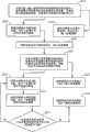
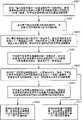
图2为本发明自输入图像取出前景图像的方法的流程简图。FIG. 2 is a schematic flowchart of the method for extracting a foreground image from an input image according to the present invention.
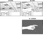
图3为依据本发明的一实施例所得到的第一前景图像以及相对应的参考背景与输入图像的示意图。FIG. 3 is a schematic diagram of a first foreground image, a corresponding reference background, and an input image obtained according to an embodiment of the present invention.
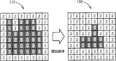
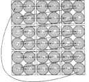
图4为依据本发明的一实施例对一对照表依序进行水平扩张、垂直扩张程序以得到对应较佳前景图像的对照表的示意图。4 is a schematic diagram of sequentially performing horizontal expansion and vertical expansion procedures on a lookup table to obtain a lookup table corresponding to a better foreground image according to an embodiment of the present invention.
图5为依据本发明的一实施例所得到的第二前景图像以及相对应的输入图像的示意图。FIG. 5 is a schematic diagram of a second foreground image obtained according to an embodiment of the present invention and a corresponding input image.
图6为依据本发明的另一实施例所得到的第二前景图像以及相对应的输入图像与背景图像的示意图。FIG. 6 is a schematic diagram of a second foreground image and the corresponding input image and background image obtained according to another embodiment of the present invention.
图7为依据本发明的一实施例所得到的第三前景图像以及相对应的输入图像的示意图。FIG. 7 is a schematic diagram of a third foreground image obtained according to an embodiment of the present invention and a corresponding input image.
图8为依据本发明的一实施例来对一对照表进行一侵蚀程序以得到对应较佳前景图像的对照表的示意图。FIG. 8 is a schematic diagram of performing an erosion process on a lookup table to obtain a lookup table corresponding to a better foreground image according to an embodiment of the present invention.
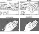
图9为依据本发明的一实施例所得到的扩张前景图像、侵蚀前景图像以及相对应的输入图像的示意图。FIG. 9 is a schematic diagram of dilated foreground images, eroded foreground images and corresponding input images obtained according to an embodiment of the present invention.
图10为应用本发明在输入图像中移除前景物体的阴影部分的方法的阴影移除模块的示意图。FIG. 10 is a schematic diagram of a shadow removal module applying the method of removing the shadow part of the foreground object in the input image of the present invention.
图11为依据本发明的一实施例自输入图像的前景图像中移除阴影的方法的流程简图。FIG. 11 is a schematic flowchart of a method for removing shadows from a foreground image of an input image according to an embodiment of the invention.
图12为依据本发明的一实施例而以一处理单位与其邻近处理单位的所有像素的亮度值来产生多个亮度自相关值的示意图。12 is a schematic diagram of generating a plurality of luminance autocorrelation values by using luminance values of all pixels in a processing unit and its adjacent processing units according to an embodiment of the present invention.
图13为经由图12中的亮度值所求得的亮度自相关值的矩阵的示意图。FIG. 13 is a schematic diagram of a matrix of luminance autocorrelation values obtained from the luminance values in FIG. 12 .
图14即为依据本发明的另一实施例而以一处理单位与其邻近处理单位的所有像素的亮度值来产生多个亮度自相关值的示意图。FIG. 14 is a schematic diagram of generating multiple luminance autocorrelation values by using the luminance values of all pixels in a processing unit and its adjacent processing units according to another embodiment of the present invention.
图15为依据本发明的一实施例上所得到的第一前景图像以及相对应的参考背景与前景图像的示意图。FIG. 15 is a schematic diagram of a first foreground image and corresponding reference background and foreground images obtained according to an embodiment of the present invention.
图16为应用本发明对前景图像进行边缘塑形的方法的边缘塑形模块的示意图。FIG. 16 is a schematic diagram of an edge shaping module applying the method for edge shaping of a foreground image according to the present invention.
图17为依据本发明的一实施例而自输入图像取出前景的方法的流程简图。FIG. 17 is a schematic flowchart of a method for extracting a foreground from an input image according to an embodiment of the present invention.
图18为图像侵蚀程序的示意图。Fig. 18 is a schematic diagram of an image erosion procedure.
图19为本发明边缘塑形程序的一实施例的示意图。Fig. 19 is a schematic diagram of an embodiment of the edge shaping procedure of the present invention.
图20为依据本发明的一实施例所得到的第二前景图像、第三前景图像以及相对应的输入图像的示意图。FIG. 20 is a schematic diagram of a second foreground image, a third foreground image and corresponding input images obtained according to an embodiment of the present invention.
上述附图中的附图标记说明如下:The reference numerals in the above-mentioned accompanying drawings are explained as follows:
100前景产生模块 300边缘塑形模块100
101前景提取单元 301边缘检测单元101
102参考背景产生单元 302边缘像素检测单元102 reference
103前景扩张单元 303边缘塑形单元103
105前景检测单元 310对照表105
107扩张侵蚀单元107 dilation erosion unit
1071扩张单元1071 Expansion Unit
1072侵蚀单元1072 Erosion Unit
110对照表110 comparison table
S201~S219、S301~S321、S401~S413步骤S201~S219, S301~S321, S401~S413 steps
200阴影移除模块200 shadow removal modules
201阴影检测单元201 shadow detection unit
202阴景内部扩张单元202 Shades Interior Expansion Unit
203阴景扩张侵蚀单元203 Shade Expansion Erosion Unit
2031阴影扩张单元2031 Shaded Expansion Unit
2032阴影侵蚀单元2032 Shadow Erosion Unit
210对照表210 comparison table
具体实施方式Detailed ways
本发明揭示了一种可成功自一输入图像取出前景的机制。首先,请参照图1,图1为应用本发明自输入图像取出前景的方法的前景产生模块100的示意图。前景产生模块100包含有一前景提取单元101、一参考背景产生单元102、一亮度产生单元104、一前景扩张单元103、一前景检测单元105、一扩张侵蚀单元107以及一对照表110,其中前景产生模块100以及各内部元件皆可以物理电路(硬件)抑或程序码(软件)的方式来实现,也即任何采用本发明自输入图像取出前景的演算法的图像处理架构均属本发明的范畴。参考背景产生单元102用以依据一预设图像IMG_PRE或输入图像IMG_IN来产生一参考背景BG_REF,其中参考背景BG_REF包含有多个处理单位分别对应至输入图像IMG_IN所包含的多个处理单位,且每一处理单位包含有多个像素。前景提取单元101耦接于参考背景产生单元102与亮度产生单元104,用以依据输入图像IMG_IN与参考背景BG_REF来产生一第一前景图像FG_1。亮度产生单元104耦接于参考背景产生单元102与前景提取单元101,用以产生多个关于输入图像IMG_IN与参考背景BG_REF的亮度值,分别对应到输入图像IMG_IN中多个处理单位与参考背景BG_REF中多个处理单位。前景扩张单元103耦接于前景提取单元101,用以接收第一前景图像FG_1并调整其为一第二前景图像FG_2。前景检测单元105耦接于前景扩张单元103,用以接收第二前景图像FG_2,并依据第二前景图像FG_2与参考背景BG_REF来产生一第三前景图像FG_3。扩张侵蚀单元107包含有一扩张单元1071以及一侵蚀单元1072,用以接收第三前景图像FG_3并决定是否输出侵蚀单元1072的处理结果以作为一第四前景图像FG_4,其中扩张单元1071耦接于前景检测单元105,用以接收一前景图像并调整其为一扩张前景图像,而侵蚀单元1072则耦接于扩张单元1071,用以接收该扩张前景图像并调整其为一侵蚀前景图像。对照表110包含有多个储存单元,分别对应至输入图像IMG_IN的多个处理单位(也对应到参考背景BG_REF的多个处理单位),且每一储存单元用来储存代表前景的一第一代码或代表背景的一第二代码。The present invention discloses a mechanism that can successfully extract the foreground from an input image. First, please refer to FIG. 1 , which is a schematic diagram of a
请配合图1来参照图2,图2为本发明自输入图像取出前景图像的方法的流程简图。倘若大体上可达到相同的结果,并不需要一定遵照图2所示的流程中的步骤顺序来进行,且图2所示的步骤不一定要连续进行,也即,其他步骤也可插入其中。本发明取出前景的步骤概述如下:Please refer to FIG. 2 in conjunction with FIG. 1 . FIG. 2 is a schematic flowchart of a method for extracting a foreground image from an input image according to the present invention. If substantially the same result can be achieved, it is not necessary to follow the order of the steps in the flow shown in FIG. 2 , and the steps shown in FIG. 2 do not have to be performed consecutively, that is, other steps can also be inserted therein. The steps of the present invention to extract the prospect are summarized as follows:
S201:分别比较一输入图像内IMG_IN的所有处理单位的亮度值与一参考背景BG_REF内的所有相对应处理单位的亮度值,并将所有比较结果储存到一对照表110中所有相对应储存单元中;S201: Compare the luminance values of all processing units of IMG_IN in an input image with the luminance values of all corresponding processing units in a reference background BG_REF, and store all comparison results in all corresponding storage units in a comparison table 110 ;
S203:依照对照表110中所述比较结果,来决定出一第一前景图像FG_1;S203: Determine a first foreground image FG_1 according to the comparison result in the comparison table 110;
S205:依照对照表中110所述比较结果,执行一前景扩张程序以更新对照表110;S205: Perform a foreground expansion procedure to update the comparison table 110 according to the comparison result described in the comparison table 110;
S207:依据更新后的对照表110来决定一第二前景图像FG_2;S207: Determine a second foreground image FG_2 according to the updated comparison table 110;
S209:分别比较第二前景图像FG_2内的所有处理单位的亮度值与参考背景内BG_REF的所有相对应处理单位的亮度值,并依据所有比较结果来更新对照表110;S209: Compare the luminance values of all processing units in the second foreground image FG_2 with the luminance values of all corresponding processing units in the reference background BG_REF, and update the comparison table 110 according to all comparison results;
S211:依据更新后的对照表110来决定一第三前景图像FG_3;S211: Determine a third foreground image FG_3 according to the updated comparison table 110;
S213:依照对照表110中所述比较结果,执行一前景扩张程序以更新对照表110;S213: Perform a foreground expansion procedure to update the comparison table 110 according to the comparison result in the comparison table 110;
S215:依照对照表110中所述比较结果,执行一前景侵蚀程序以更新对照表110;S215: Perform a foreground erosion procedure to update the comparison table 110 according to the comparison result in the comparison table 110;
S217:判断该前景扩张程序与该前景侵蚀程序是否已达到一预定循环次数?若已达到该预定循环次数,则进行步骤S219;若尚未达到该预定循环次数,则回到步骤S213;S217: Determine whether the foreground expansion procedure and the foreground erosion procedure have reached a predetermined number of cycles? If the predetermined number of cycles has been reached, proceed to step S219; if the predetermined number of cycles has not been reached, then return to step S213;
S219:依据更新后的对照表110来决定一第四前景图像FG_4。S219: Determine a fourth foreground image FG_4 according to the updated comparison table 110 .
由于当一前景物体在参考背景BG_REF中出现时,该前景物体所占用的像素通常会与该前景物体尚未出现时的像素不同,尤其是在亮度上会有极大的差异,是故前景产生模块100在接收到输入图像IMG_IN后,会应用亮度产生单元104来分别处理输入图像IMG_IN以及背景图像BG_REF,为了节省处理时间,通常会以多个像素所组成的处理单位为基准来得到对应输入图像IMG_IN以及背景图像BG_REF内每一处理单位的亮度值(举例来说,该亮度值可为该处理单位内所有像素亮度的总和或是平均),然后前景提取单元101会分别比较输入图像IMG_IN内的所有处理单位的亮度值与参考背景BG_REF内的所有相对应处理单位的亮度值;若输入图像IMG_IN内的一处理单位的亮度值较参考背景BG_REF内的一相对应处理单位的亮度值的差量大于或等于一第一门槛值,则指定第一代码给对照表110中一相对应储存单元;反之,若输入图像IMG_IN内的该处理单位的亮度值较参考背景BG_REF内的该相对应处理单位的亮度值的差量小于该第一门槛值,则指定第二代码给该照表110中该相对应储存单元(步骤S201)。之后,前景提取单元101便依据对照表110内具有第一代码的每一储存单元来决定出第一前景图像FG_1,意即,前景提取单元101仅输出输入图像IMG_IN中,对应第一代码的所有处理单位以作为第一前景图像FG_1来当作一个初步的结果,如步骤S203。请参照图3,图3为所得到的第一前景图像FG_1以及相对应的一参考背景BG_REF与一输入图像IMG_IN的一实施例的示意图,由图可知,上述步骤可确实得到一个粗略的前景处理结果。Because when a foreground object appears in the reference background BG_REF, the pixels occupied by the foreground object are usually different from the pixels when the foreground object has not yet appeared, especially there will be a huge difference in brightness, so the foreground generation module After receiving the input image IMG_IN, 100 will use the
为了得到更进一步的前景处理结果,本实施例另应用了前景扩张单元103,其在接收到第一前景图像FG_1后,依据对照表110对每一储存单元执行前景扩张程序:若第一前景图像FG_1中对应一特定储存单元的一特定处理单位的水平方向上具有对应第一代码的邻近处理单位于该特定处理单位左方与右方一水平距离内的数量均超过一水平门槛值,则指定第一代码给该特定储存单元来取代原本的第二代码;接着,在对每一储存单元进行完水平扩张程序后,若该第一前景图像FG_1对应一特定储存单元的一特定处理单位的垂直方向上,对应第一代码的邻近处理单位于该特定处理单位上方与下方一垂直距离内的数量均超过一垂直门槛值,则指定第一代码给该特定储存单元来取代原本的第二代码,如步骤S205。之后,前景扩张单元103依据对照表110内具有第一代码的每一储存单元来决定出第二前景图像FG_2,如步骤S207。请注意,在此并不限定须先进行水平方向的扩张再进行垂直方向的扩张,而先进行垂直方向的扩张再进行水平方向的扩张的设计变化也落在本发明的范畴之内。In order to obtain further foreground processing results, this embodiment additionally employs the
举例来说,图4示出了本实施例中的对照表110依序进行水平扩张与垂直扩张程序以得到对应一较佳前景图像的对照表110。在此范例中,内有标号1的方格为具有第一代码的储存单元,在此先称之为前景方格,而内有标号2的方格为具有第二代码的储存单元,在此先称之为背景方格。当一背景方格的水平方向上,与该背景方格左方与右方一水平距离内相邻的前景方格(该水平距离等于一处理单位)的数量均大于1时(水平门槛值等于1),则将该背景方格改为内含有标号1的前景方格;同理,在处理完所有背景方格的水平扩张程序后,当一背景方格的垂直方向上,与该背景方格上方与下方一垂直距离内相邻的前景方格(该垂直距离等于一处理单位)的数量均大于1时(垂直门槛值等于1),则将该背景方格改为内含有标号1的前景方格,由此一来,原本在步骤S201中未能正确判定的前景图像也能确实地呈现出来(如图4的最后结果所示)。请注意,上述的水平距离、垂直距离、水平门槛值与垂直门槛值可依设计上的考虑而加以修改,比方说采用一较宽松的扩张程序时,水平距离与垂直距离可设定为三个处理单位,而水平门槛值与垂直门槛值可设定为1,如此一来,便可得到一扩张程度较高的一前景图像。再请参照图5,图5为依据一实施例所得到的一第二前景图像FG_2以及相对应的一输入图像IMG_IN的示意图。与图3所示的第一前景图像FG_1比较,可知上述扩张程序可确实得到一较佳的前景图像。For example, FIG. 4 shows that the comparison table 110 in this embodiment performs horizontal expansion and vertical expansion procedures sequentially to obtain the comparison table 110 corresponding to a better foreground image. In this example, the square with the
然而,扩张程序有时会导致错误的前景图像结果,请参照图6,图6为依据另一实施例所得到的第二前景图像FG_2以及相对应的输入图像IMG_IN与参考背景图像BG_REF的示意图。图6中的第二前景图像FG_2会经由前景扩张程序,将被前景图像环绕的一背景图像误判为一前景图像而提取出来,因而得到一个错误的前景图像结果。为避免发生这一类的误判,前景检测模块105在接收到第二前景图像FG-2后,会再次分别比较第二前景图像FG_2内的所有处理单位的亮度值与参考背景BG_REF内的所有相对应处理单位的亮度值,若第二前景图像内FG_2的一处理单位的亮度值较参考背景BG_REF内的一相对应处理单位的亮度值的差量大于或等于一第二门槛值,则指定第一代码给对照表110中一相对应储存单元;反之若第二前景图像FG_2内的该处理单位的亮度值较参考背景BG_REF内的该相对应处理单位的亮度值的差量小于该第二门槛值,则指定第二代码给对照表110中该相对应储存单元,如步骤S209。之后,前景检测模块105便依据对照表110内具有第一代码的每一储存单元来决定出第三前景图像FG_3,如步骤S211。在本实施例中,该第二门槛值较该第一门槛值来得小,其用意在于让前景提取单元101得以较严格的条件,提取出初步的第一前景图像FG_1,再经由前景扩张单元103找出无法通过严格条件的前景图像来决定第二前景图像FG_2,而后前景检测单元105则以较宽松的条件去除前景扩张单元103误判的图像,并同时保留已正确找出的前景图像。再请参照图7,图7为依据一实施例所得到的一第三前景图像以及相对应的一输入图像的示意图,与图6所示的第二前景图像FG_2比较,可知上述程序可确实得到一较佳的前景图像。However, the dilation process sometimes leads to wrong foreground image results. Please refer to FIG. 6 , which is a schematic diagram of the second foreground image FG_2 and the corresponding input image IMG_IN and reference background image BG_REF obtained according to another embodiment. The second foreground image FG_2 in FIG. 6 is extracted by misjudging a background image surrounded by the foreground image as a foreground image through the foreground expansion process, thus obtaining a wrong foreground image result. In order to avoid this type of misjudgment, after receiving the second foreground image FG-2, the
然而,本发明更进一步地应用扩张侵蚀单元107来进行一扩张侵蚀程序以得到一较佳的前景图像。扩张侵蚀单元107中的扩张单元1071首先依照对照表110执行一前景扩张程序以更新对照表110来得到一前景扩张图像,相关程序与步骤S205相似,故于此不再赘述,如步骤S213。接着,扩张侵蚀单元107中的侵蚀单元10721再依照扩张单元1071所更新过的对照表110来对每一储存单元执行一前景侵蚀程序:以该前景扩张图像中对应一特定储存单元的一特定处理单位来说,若对应第一代码且相距一预定距离内的邻近处理单位的数量小于一侵蚀门槛值,则指定第二代码给该特定储存单元来取代原本的第一代码,如步骤S215。举例来说,图8示出了本实施例中一对照表110进行侵蚀程序以得到对应一较佳的前景图像的对照表110。在此范例中,内含有标号1的方格为具有第一代码的储存单元,在此先称之为前景方格,而内含有标号2的方格为具有第二代码的储存单元,在此先称之为背景方格;对一特定前景方格来说,当与其相距一处理单位(即预定距离为一处理单位)内的邻近前景方格的数量小于8时(即侵蚀门槛值等于8),则将该前景方格改为内含有标号2的背景方格,由此一来,原本在步骤S215中未能正确判定的背景图像也能确实地呈现出来(如图9的结果所示)。However, the present invention further uses the dilation and
此外,在本发明中,为了得到一较佳的前景图像,扩张侵蚀单元107会不断地依序进行步骤S213、S215中的扩张、侵蚀程序,直到完成一预定扩张侵蚀循环次数为止,如步骤S217。接着,扩张侵蚀单元107再依据更新后的对照表110来决定出一第四前景图像FG_4,如步骤S219。In addition, in the present invention, in order to obtain a better foreground image, the dilation and
此外,本发明另提供了一种在一输入图像中移除至少一前景物体的阴影部分的机制。请参照图10,图10为应用本发明在输入图像中移除前景物体的阴影部分的方法的阴影移除模块200的示意图。阴影移除模块200包含有一阴影检测单元201、一阴影扩张单元202、一阴影扩张蚀侵单元203以及一对照表210,其中阴影移除模块200以及各内部元件皆可以物理电路(硬件)抑或程序码(软件)来实现,也即任何采用本发明在输入图像中移除前景物体的阴影部分的演算法的图像处理架构均属本发明的范畴。阴影检测单元201用以接收对应该输入图像的一前景图像FG,依据对应该输入图像的一参考背景BG_REF,检测前景图像FG中至少一前景物件的阴影部分以产生一检测结果并依据该检测结果来决定该输入图像中的一第一前景图像FG_1。阴影扩张单元202耦接于阴影检测单元201,用以接收第一前景图像FG_1并调整其为一第二前景图像FG_2。扩张侵蚀单元203包含有一阴影扩张单元2031以及一阴影侵蚀单元2032,用以接收第二前景图像FG_2并决定是否输出阴影侵蚀单元2032的处理结果来作为一第三前景图像FG_3;其中阴影扩张单元2031耦接于阴影检测单元201,用以接收一前景图像并调整其为一阴影扩张图像;而阴影侵蚀单元2032耦接于阴影扩张单元2031,用以接收该阴影扩张图像并调整其为一阴影侵蚀图像。对照表210包含有多个储存单元,分别对应至该输入图像的多个处理单位(也对应到参考背景BG_REF的多个处理单位),且每一储存单元用来储存代表前景的一第一代码或代表非前景的一第二代码。In addition, the present invention further provides a mechanism for removing the shadow portion of at least one foreground object in an input image. Please refer to FIG. 10 . FIG. 10 is a schematic diagram of a
请配合图10来一并参照图11,图11为本发明自一输入图像的一前景图像中移除阴影的方法的流程简图。倘若大体上可达到相同的结果,并不需要一定遵照图11所示的流程中的步骤顺序来进行,且图11所示的步骤不一定要连续进行,也即,其他步骤也可插入其中。本发明移除阴影的步骤概述如下:Please refer to FIG. 11 together with FIG. 10 . FIG. 11 is a flowchart of a method for removing a shadow from a foreground image of an input image according to the present invention. If substantially the same result can be achieved, it is not necessary to follow the order of the steps in the flow shown in FIG. 11 , and the steps shown in FIG. 11 do not have to be performed consecutively, that is, other steps can also be inserted therein. The steps of shadow removal in the present invention are summarized as follows:
S301:分别比较一前景图像FG内的所有处理单位的亮度值与一参考背景BG REF内的所有相对应处理单位的亮度值以产生一亮度比较结果;S301: Compare the luminance values of all processing units in a foreground image FG with the luminance values of all corresponding processing units in a reference background BG REF to generate a luminance comparison result;
S303:分别比较前景图像FG内的所有处理单位的色度值与参考背景BG_REF内的所有相对应处理单位的色度值以产生一色度比较结果;S303: Compare the chromaticity values of all processing units in the foreground image FG with the chromaticity values of all corresponding processing units in the reference background BG_REF to generate a chromaticity comparison result;
S305:分别比较前景图像FG内的所有处理单位的亮度自相关值(autocorrelation)与参考背景BG_REF内的所有相对应处理单位的亮度自相关值以产生一亮度自相关值比较结果;S305: Compare brightness autocorrelation values (autocorrelation) of all processing units in the foreground image FG with brightness autocorrelation values of all corresponding processing units in the reference background BG_REF to generate a brightness autocorrelation value comparison result;
S307:依据该亮度比较结果、该色度比较结果以及该亮度自相关值比较结果来更新对照表210;S307: Update the comparison table 210 according to the brightness comparison result, the chromaticity comparison result, and the brightness autocorrelation value comparison result;
S309:依据更新后的对照表210来决定一第一前景图像FG_1;S309: Determine a first foreground image FG_1 according to the updated comparison table 210;
S311:依照对照表210来执行一阴影内部扩张程序以更新对照表210;S311: Execute a shadow internal expansion procedure according to the comparison table 210 to update the comparison table 210;
S313:依据更新后的对照表210来决定一第二前景图像FG_2;S313: Determine a second foreground image FG_2 according to the updated comparison table 210;
S315:依照对照表210来执行一阴影扩张程序以更新对照表210;S315: Execute a shadow expansion program according to the comparison table 210 to update the comparison table 210;
S317:依照对照表210来执行一阴影侵蚀程序以更新对照表210;S317: Execute a shadow erosion program according to the lookup table 210 to update the lookup table 210;
S319:判断该阴影扩张程序与该阴影前景侵蚀程序是否已达到一预定循环次数?若已达到一预定循环次数,则进行步骤S219;若未达到一预定循环次数,回到步骤S313;S319: Determine whether the shadow expansion procedure and the shadow foreground erosion procedure have reached a predetermined number of cycles? If a predetermined number of cycles has been reached, proceed to step S219; if a predetermined number of cycles has not been reached, return to step S313;
S321:依据更新后的对照表210来决定一第三前景图像FG_3。S321: Determine a third foreground image FG_3 according to the updated comparison table 210 .
当一前景物体的一阴影落在一部分背景图像时,该部分背景图像会与该阴影未出现时的图像(也就是在参考背景BG_REF中的该部分背景图像)在亮度、色度以及纹路(亮度自相关性)上会有相当程度的相似。因此,阴影检测单元201会在接收到前景图像FG后,以上述的亮度、色度以及亮度自相关性来决定前景图像FG中的阴影部分。为了节省处理时间,通常会以多个像素所组成的处理单位为基准来进行上述步骤。首先,阴影检测单元201会针对前景图像FG中每一处理单位(即于对照表210中具有代表非前景的第二代码的储存单位所对应的处理单位),比较前景图像FG的该处理单位的亮度值与参考背景BG_REF内的一相对应处理单位的亮度值,以判断当前景图像FG中该处理单位的亮度值是否皆低于参考背景BG_REF内的该相对应处理单位的亮度值,如步骤S301。接下来,阴影检测单元201会比较前景图像FG中该处理单位中每一像素的色度值与位于参考背景BG_REF内该相对应处理单位中相对应像素的色度值,以判断该处理单位与参考背景BG_REF中色度值的差距小于一色度门槛值的像素的数量是否超过一阴影门槛值,如步骤S303。再来,阴影检测单元201会依据该处理单位以及其邻近处理单位的所有像素的亮度值来产生多个第一亮度自相关值,并依据参考背景BG_REF内的一相对应处理单位以及其邻近处理单位的所有像素的亮度值来产生多个第二亮度自相关值,而后,阴影检测单元201会判断该多个第一亮度自相关值与该多个第二亮度自相关值中,亮度自相关值相同的个数是否超过一阴影门槛值,如步骤S305。在完成上述三项比较之后,阴影检测单元201便依据该亮度比较结果、该色度比较结果以及该亮度自相关值比较结果来更新对照表210,如步骤S307。When a shadow of a foreground object falls on a part of the background image, the part of the background image will be different from the image when the shadow does not appear (that is, the part of the background image in the reference background BG_REF) in terms of brightness, chroma and texture (brightness). Autocorrelation) will have a considerable degree of similarity. Therefore, after receiving the foreground image FG, the
请参照图12以及图13来进一步了解步骤S305中得到亮度自相关值比较结果的运作。为了求得较详尽的亮度自相关值(纹路),本发明的一实施例中以一处理单位为中心,并将该处理单位相距一处理单位内的邻近处理单位都加入计算,假设所采用的每一处理单位内包含有4个像素,则在此对该处理单位的计算会包含有36个像素的亮度值。图12为依据本发明一实施例以一处理单位与其邻近处理单位的所有像素的亮度值来产生多个亮度自相关值的示意图,而图13为依据12图中所有像素的亮度值所产生的亮度自相关值的示意图。于图12中,每个方格代表一个处理单位,每个圆圈代表一个像素,而每个像素都具有一亮度Pn与一亮度自相关值An,其中n等于0~35。在图13的范例中,亮度自相关值An定义为代表一像素的亮度Pn是否高于相邻像素亮度值Pn+1的数值,当Pn+1≥Pn,An=1;反之,若Pn+1<Pn,An=-1,而最后一个像素的亮度自相关值A35,则是由P35与P0决定,当P0≥P35,A35=1;反之,若P0<P35,A35=-1。最后,经由上述的运算可得到一亮度自相关值An的矩阵,如图13所示。请注意,上述图12所示的亮度自相关值An的计算程序仅为一可能的实现方式,只要能使结果具有代表相邻像素亮度差距的关系,亮度自相关值An也可由其他运算方式来求得,如图14即为依据本发明另一实施例以一处理单位与其邻近处理单位的所有像素的亮度值来产生多个亮度自相关值的示意图。Please refer to FIG. 12 and FIG. 13 to further understand the operation of obtaining the brightness autocorrelation value comparison result in step S305 . In order to obtain more detailed luminance autocorrelation values (textures), in one embodiment of the present invention, a processing unit is taken as the center, and adjacent processing units within one processing unit distance from the processing unit are added to the calculation, assuming that the adopted Each processing unit includes 4 pixels, and the calculation of the processing unit here will include brightness values of 36 pixels. FIG. 12 is a schematic diagram of generating a plurality of luminance autocorrelation values based on the luminance values of all pixels in a processing unit and its adjacent processing units according to an embodiment of the present invention, and FIG. 13 is a schematic diagram of generating a plurality of luminance autocorrelation values based on the luminance values of all pixels in FIG. 12 Schematic representation of luminance autocorrelation values. In FIG. 12 , each grid represents a processing unit, each circle represents a pixel, and each pixel has a brightness Pn and a brightness autocorrelation value An, wherein n is equal to 0-35. In the example shown in Figure 13, the luminance autocorrelation value An is defined as a value representing whether the luminance Pn of a pixel is higher than the luminance value Pn+1 of an adjacent pixel. When Pn+1≥Pn, An=1; otherwise, if
在步骤S305中,阴影检测单元201在运用上述亮度自相关值的计算后,可分别针对前景图像FG中一处理单位与参考背景BG_REF中一相对应处理单位,得到一第一亮度自相关值(例如Bn)与一第二亮度自相关值(例如Cn)的两个矩阵,由于这两个矩阵皆由1与-1所组成,当第一亮度自相关值Bn与相对应的第二亮度自相关值Cn同号时,Bn*Cn=1;反之,当第一亮度自相关值Bn与相对应的第二亮度自相关值Cn异号时,Bn*Cn=-1。而Bn与Cn同号的数目愈多,代表前景图像FG中的该处理单位与参考背景BG_REF中该相对应处理单位的纹路愈相近,是故在实作上,阴影检测单元201会以∑Bn*Cn大于一阴影门槛值来判定该处理单位是否应隶属于阴影部分。In step S305, the
在完成亮度、色度以及亮度自相关值比较之后,阴影检测单元201会依据所述比较结果来决定前景图像FG中每一处理单位是否属于阴影部分,若阴影检测单元201判断该处理单位属于阴影部分,则指定代表非前景的第二代码给该特定储存单元来取代原本代表前景的第一代码,以更新对照表210,如步骤S307。之后,阴影检测单元201依据对照表210内具有第一代码的每一储存单元来决定出第一前景图像FG_1,如步骤S309。After completing the comparison of luminance, chroma and luminance autocorrelation values, the
接下来,阴影内部扩张单元202依据对照表210对每一储存单元执行一阴影内部扩张程序:若第一前景图像FG_1中对应一特定储存单元的一特定处理单位的水平方向上具有对应第二代码的邻近处理单位于该特定处理单位左方与右方一水平距离内的数量均超过一阴影水平门槛值,则指定第二代码给该特定储存单元来取代原本的第一代码;接着,在对每一储存单元进行完阴影水平扩张程序后,若第一前景图像FG_1中对应一特定储存单元的一特定处理单位的垂直方向上,对应第二代码的邻近处理单位于该特定处理单位上方与下方一垂直距离内的数量均超过一阴影垂直门槛值,则指定第二代码给该特定储存单元来取代原本的第一代码,如步骤S311。之后,阴影内部扩张单元202便依据更新后的对照表210内具有代表前景的第一代码的每一储存单元来决定出第二前景图像FG_2,如步骤S313。请注意,在此并不限定须先进行水平方向的扩张再进行垂直方向的扩张,也即,先进行垂直方向的扩张再进行水平方向的扩张的设计变化也落在本发明的范畴之内。Next, the shadow
然而,本发明更进一步地应用阴影扩张侵蚀单元203来进行一扩张侵蚀程序以得到一较佳的前景图像。扩张侵蚀单元203中的阴影扩张单元2031首先依照对照表210执行一阴影扩张程序以更新对照表210来得到一阴影扩张图像,相关程序与步骤S311相似,故于此不再赘述,如步骤S315。接着,阴影扩张侵蚀单元203中的阴影侵蚀单元2032再依照阴影扩张单元2031所更新过的对照表110来对每一储存单元执行一阴影侵蚀程序:以该阴影扩张图像中对应一特定储存单元的一特定处理单位来说,若对应代表非前景的第二代码且相距一预定距离内的邻近处理单位的数量小于一阴影侵蚀门槛值,则指定代表前景的第一代码给该特定储存单元来取代原本的第二代码,如步骤S317。阴影扩张侵蚀单元203会不断地依序进行步骤S315、S317中的阴影扩张、阴影侵蚀程序,直到完成一预定扩张侵蚀循环次数为止,如步骤S319。接着,阴影扩张侵蚀单元203再依据更新后的对照表210来决定出一第三前景图像FG_3,如步骤S321。However, the present invention further uses the shadow dilation and
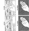
请参照图15,图15为一实施例所得到的一第一前景图像FG_1以及相对应的一参考背景BG_REF与一前景图像FG的示意图。由图可知,上述步骤确实可在一前景图像FG中移除一前景物体的阴影部分。Please refer to FIG. 15 , which is a schematic diagram of a first foreground image FG_1 and a corresponding reference background BG_REF and a foreground image FG obtained by an embodiment. It can be seen from the figure that the above steps can indeed remove the shadow portion of a foreground object in a foreground image FG.
再者,本发明另提供了一种对一前景图像进行边缘塑形的机制。请参照图16,图16为应用本发明对前景图像进行边缘塑形的方法的边缘塑形模块300的示意图。边缘塑形模块300包含有一边缘检测单元301、一边缘像素检测单元302、一边缘塑形单元303以及一对照表310,其中边缘塑形模块300以及各内部元件皆可以物理电路(硬件)抑或程序码(软件)来实现,也即任何采用本发明对前景图像进行边缘塑形的演算法的图像处理架构均属本发明的范畴。边缘检测单元301用以接收对应一输入图像的一前景图像FG,并检测前景图像FG中至少一前景物件的边缘以产生一第一检测结果(其对应第一前景图像FG_1)。边缘像素检测单元302耦接于边缘检测单元301,用以依据该第一检测结果来检测该前景图像中至少一前景物件的边缘以产生一第二检测结果(其对应第二前景图像FG_2)。边缘塑形单元303耦接于边缘像素检测单元302,用以依据该第二检测结果来对第二前景图像FG_2进行一边缘塑形程序,并输出一第三前景图像FG_3。此外,请注意,边缘塑形模块300可依据需求而直接输出边缘像素检测单元302所产生的第二前景图像FG_2,或者输出边缘像素检测单元302所产生的第二前景图像FG_2经由边缘塑形单元303处理过的第三前景图像FG_3。对照表310则包含有多个储存单元,分别对应至该输入图像的多个处理单位,每一处理单位包含有多个像素,且每一储存单元系用来储存代表前景的一第一代码、代表非边缘前景的一第二代码或代表背景边缘的一第三代码。Furthermore, the present invention provides a mechanism for edge shaping of a foreground image. Please refer to FIG. 16 . FIG. 16 is a schematic diagram of an
请配合图16来一并参照图17,图17为本发明自一输入图像取出前景的方法的流程简图。倘若大体上可达到相同的结果,并不需要一定遵照图17所示的流程中的步骤顺序来进行,且图17所示的步骤不一定要连续进行,也即,其他步骤也可插入其中。本发明边缘塑形的步骤概述如下:Please refer to FIG. 17 together with FIG. 16 . FIG. 17 is a schematic flowchart of a method for extracting a foreground from an input image according to the present invention. If substantially the same result can be achieved, it is not necessary to follow the order of the steps in the flow shown in FIG. 17 , and the steps shown in FIG. 17 do not have to be performed consecutively, that is, other steps can also be inserted therein. The steps of edge shaping of the present invention are summarized as follows:
S401:针对一输入图像中属于一前景图像的每一处理单位,若该处理单位的邻近处理单位中属于前景图像的数量没有超过一内景门槛值,则将该处理单位归类为前景非边缘图像;S401: For each processing unit belonging to a foreground image in an input image, if the number of foreground images in adjacent processing units of the processing unit does not exceed an interior threshold, classify the processing unit as a foreground non-edge image ;
S403:去除属于非边缘前景图像的处理单位,将其他前景图像归类为前景边缘图像;S403: Remove processing units belonging to non-edge foreground images, and classify other foreground images as foreground edge images;
S405:针对属于该前景边缘图像的每一处理单位,若与该储存单元的距离小于一特定距离内有一特定处理单位不属于前景边缘图像或前景非边缘图像,将该特定处理单位归类为背景边缘图像;S405: For each processing unit belonging to the foreground edge image, if a specific processing unit within a distance from the storage unit is less than a specific distance and does not belong to the foreground edge image or the foreground non-edge image, classify the specific processing unit as background edge image;
S407:针对属于该背景边缘图像的每一处理单位,找出该处理单位中所有像素与该处理单位的多个邻近像素中具有最高亮度的一像素来作为一参考像素;S407: For each processing unit belonging to the background edge image, find a pixel with the highest brightness among all pixels in the processing unit and a plurality of neighboring pixels of the processing unit as a reference pixel;
S409:针对属于该背景边缘图像的每一处理单位内每一像素,当该处理单位中像素与该参考像素的亮度差超过一预设门槛值时,将该像素归类为边缘像素;反之,将该像素归类为非边缘像素;S409: For each pixel in each processing unit belonging to the background edge image, when the brightness difference between the pixel in the processing unit and the reference pixel exceeds a preset threshold value, classify the pixel as an edge pixel; otherwise, Classify the pixel as a non-edge pixel;
S411:依据所述前景非边缘图像、所述前景边缘图像以及所述边缘像素以输出一第二前景图像FG_2;S411: Output a second foreground image FG_2 according to the foreground non-edge image, the foreground edge image, and the edge pixels;
S413:针对属于该背景边缘图像的每一处理单位,依据该处理单位的邻近处理单位是否属于前景边缘图像来决定是否将该处理单位内的像素归类为背景像素;S413: For each processing unit belonging to the background edge image, determine whether to classify the pixels in the processing unit as background pixels according to whether the adjacent processing units of the processing unit belong to the foreground edge image;
S415:依据所述前景非边缘图像、所述前景边缘图像以及所述边缘像素以输出一第三前景图像FG_3。S415: Output a third foreground image FG_3 according to the foreground non-edge image, the foreground edge image, and the edge pixels.
边缘检测单元301在接收到对应一输入图像的前景图像FG后,便会进行一侵蚀程序以找出前景图像FG中不属于边缘的部分:针对一输入图像中属于一前景图像FG(也就是对应具有第一代码的储存单元)的每一处理单位,若该处理单位的邻近处理单位中属于前景图像的数量没有超过一内景门槛值,则将该处理单位归类为前景非边缘图像,并指定一代表非边缘前景的第二代码给该处理单位所对应的储存单元以取代原本的第一代码,如步骤S401。如此一来,边缘检测单元301在去除属于非边缘前景图像的处理单位后,便可求得其他余下的前景图像即为前景边缘图像,此时,所有属于前景边缘图像的处理单位对应的储存单元皆具有第一代码,而属于前景非边缘图像的处理单位对应的储存单元则具有第二代码,如步骤S403。After the
为了进一步说明上述的侵蚀程序,请配合图18来参照下列的方程序:In order to further illustrate the above erosion procedure, please refer to the following equation in conjunction with Figure 18:
β(A)=A-(A Erosed by B)(1)β(A)=A-(A Erosed by B)(1)
在图18中,在一输入图像中,斜线部分即为一前景图像A,而B则是一侵蚀用的遮罩,侵蚀程序首先会将遮罩B应用在输入图像的每一个处理单位(即每一个方格),当遮罩B内有任一个处理单位不是属于前景图像时,该侵蚀程序便将此时遮罩B中心的处理单位归类为非前景单位(即图中所示的空白方格),之后可得到一侵蚀后的前景AθB(即步骤S401的动作)。接下来,在前景图像A中去除侵蚀后的前景AθB便可得到前景图像A的边缘图像β(A)(即步骤S403的动作)。In Fig. 18, in an input image, the oblique part is a foreground image A, and B is a mask for erosion. The erosion program will first apply mask B to each processing unit of the input image ( That is, each square), when there is any processing unit in the mask B that does not belong to the foreground image, the erosion program will classify the processing unit in the center of the mask B as a non-foreground unit (that is, as shown in the figure blank square), and then an eroded foreground AθB can be obtained (that is, the action of step S401). Next, remove the eroded foreground AθB from the foreground image A to obtain the edge image β(A) of the foreground image A (that is, the action of step S403).
接下来,边缘检测单元301针对属于该前景边缘图像的每一处理单位来进行处理,若以该处理单位为中心,当周遭一特定距离内(例如紧邻该处理单位的其它处理单位)有一特定处理单位不属于前景边缘图像或前景非边缘图像,则将该特定处理单位归类为背景边缘图像,并指定一代表背景边缘的第三代码给该特定处理单位所对应的储存单元,如步骤S405。步骤S405的主要用意在于找出前景边缘外恰好一个处理单位的背景以利接下来像素等级的处理。接着,边缘像素检测单元302会针对属于该背景边缘图像(也就是对应具有第三代码的储存单元)的每一像素,找出与其距离一个像素的邻近像素中具有最高亮度的一像素来作为一对应参考像素,如步骤S407。下一步,边缘像素检测单元302会在属于该背景边缘图像的每一处理单位中,分别比较每一个像素与该对应参考像素的亮度,当其中一个像素与该对应参考像素的亮度差超过一预设门槛值时,边缘像素检测单元302便将该像素归类为边缘像素并指定一边缘代码给该像素;反之,当该像素与该对应参考像素的亮度差未超过一预设门槛值时,则将该像素归类为非边缘像素并指定一非边缘代码给该像素,如步骤S409。边缘像素检测单元302接着依据所述前景非边缘图像、所述前景边缘图像以及所述边缘像素以输出一第二前景图像FG_2,如步骤S411。Next, the
其中,步骤S407、S409的用意在于找出背景图像中属于前景物体的边缘的像素。由于属于边缘的像素在亮度上通常会较一般像素低,是故步骤S407会在包含一处理单位本身像素与该处理单位邻近的像素(也即不属于该处理单位而位于该处理单位周遭一特定距离内的像素,例如环绕该处理单位的边界的像素)之中找出最亮的像素(也就是其中最接近属于非背景像素的一像素)来与其他像素作比较,当该处理单位中一个特定像素与该参考像素的亮度差过大时,即代表该特定像素属于非背景像素可能性很小;另一方面来说,当该处理单位中一个特定像素与该参考像素的亮度差不大时,即代表该特定像素属于非背景像素可能性很高。Wherein, the purpose of steps S407 and S409 is to find the pixels belonging to the edge of the foreground object in the background image. Since the pixels belonging to the edge are usually lower in brightness than the normal pixels, step S407 is to select pixels including the pixels of a processing unit and adjacent to the processing unit (that is, not belonging to the processing unit but located around the processing unit for a specific Among the pixels within the distance, such as pixels surrounding the boundary of the processing unit, find the brightest pixel (that is, the closest pixel belonging to a non-background pixel) to compare with other pixels. When a When the brightness difference between a specific pixel and the reference pixel is too large, it means that the specific pixel is less likely to belong to a non-background pixel; on the other hand, when the brightness difference between a specific pixel in the processing unit and the reference pixel is not large , it means that the specific pixel is highly likely to be a non-background pixel.
在得到一初步的第二前景图像FG_2后,边缘塑形单元303会针对属于该背景边缘图像的每一处理单位(也就是对应具有第三代码的储存单元),依据该处理单位的邻近处理单位是否属于前景边缘图像来决定是否将该处理单位内的各个像素归类为一背景像素,如步骤S413。最后,边缘塑形单元303依据所述前景非边缘图像、所述前景边缘图像以及所述边缘像素以输出一第三前景图像FG_3,如步骤S415。举例来说,请参照图19,图19为依据本发明边缘塑形程序的一实施例的示意图,其中,黑色的圆圈代表背景像素,画有斜线的圆圈代表边缘像素或是非边缘像素,而空白的圆圈则代表属于前景边缘图像的一处理单位内的像素,由图可知,边缘塑形单元303会于背景边缘图像的处理单位中,将离属于前景边缘图像的处理单位较远的像素归类为背景像素而在最后输出图像时忽略所述背景像素,其他离属于前景边缘图像的处理单位较近的像素则保持不变,如此一来,可使最后输出的图像变得较为平滑。再请参照图20,图20为依据一实施例所得到的一第二前景图像FG_2、一第三前景图像FG_3以及相对应的一输入图像IMG_IN的示意图,比较第二前景图像FG_2与第三前景图像FG_3,可知上述边缘塑形程序可确实得到一较佳的前景图像。After obtaining a preliminary second foreground image FG_2, the
请注意,上述三种图像处理方法可依据应用上的需求而各自独立运作或互相搭配应用,比方说,在期望得到一最佳视觉效果的前景时,可同时采用上述的三种方法来实现前景图像的提取,来获得一去除阴影并在边缘有较平滑视觉效果的前景图像,换言之,图1所示的前景产生模块100基于图2所示的流程所产生的第四前景图像作为图10所示的阴影移除产生模块200与图11所示的流程所欲处理的前景图像FG,而图10所示的阴影移除产生模块200基于图11所示的流程所产生的第三前景图像FG_3则作为图16所示的边缘塑形模块300与图17所示的流程所欲处理的前景图像FG,而图16所示的边缘塑形模块300基于图17所示的流程所产生的第三前景图像FG_3即为具有最佳视觉效果的前景。Please note that the above three image processing methods can operate independently or in conjunction with each other according to the application requirements. For example, when expecting to obtain a foreground with the best visual effect, the above three methods can be used at the same time to achieve the foreground. image extraction to obtain a foreground image that removes shadows and has a smoother visual effect at the edge. In other words, the fourth foreground image generated by the
背景去除的图像处理方法例中,更进一步地对一图像(例如上述的移除前景物体的阴影部分后的图像)使用边缘塑形来得到一较佳的前景图像。In the example of the image processing method for background removal, edge shaping is further used on an image (such as the above-mentioned image after removing the shadow portion of the foreground object) to obtain a better foreground image.
以上所述仅为本发明的较佳实施例,凡依本发明权利要求所做的均等变化与修饰,皆应属本发明的涵盖范围。The above descriptions are only preferred embodiments of the present invention, and all equivalent changes and modifications made according to the claims of the present invention shall fall within the scope of the present invention.
Claims (28)
Priority Applications (1)
| Application Number | Priority Date | Filing Date | Title |
|---|---|---|---|
| CN 200910146272CN101930591B (en) | 2009-06-26 | 2009-06-26 | Image Processing Methods for Background Removal |
Applications Claiming Priority (1)
| Application Number | Priority Date | Filing Date | Title |
|---|---|---|---|
| CN 200910146272CN101930591B (en) | 2009-06-26 | 2009-06-26 | Image Processing Methods for Background Removal |
Publications (2)
| Publication Number | Publication Date |
|---|---|
| CN101930591Atrue CN101930591A (en) | 2010-12-29 |
| CN101930591B CN101930591B (en) | 2013-03-06 |
Family
ID=43369751
Family Applications (1)
| Application Number | Title | Priority Date | Filing Date |
|---|---|---|---|
| CN 200910146272Expired - Fee RelatedCN101930591B (en) | 2009-06-26 | 2009-06-26 | Image Processing Methods for Background Removal |
Country Status (1)
| Country | Link |
|---|---|
| CN (1) | CN101930591B (en) |
Cited By (2)
| Publication number | Priority date | Publication date | Assignee | Title |
|---|---|---|---|---|
| CN102663713A (en)* | 2012-04-17 | 2012-09-12 | 浙江大学 | Background subtraction method based on color constant parameters |
| CN106023113A (en)* | 2016-05-27 | 2016-10-12 | 哈尔滨工业大学 | Satellite high-score image shadow region recovery method based on non-local sparse |
Family Cites Families (2)
| Publication number | Priority date | Publication date | Assignee | Title |
|---|---|---|---|---|
| CN100495438C (en)* | 2007-02-09 | 2009-06-03 | 南京大学 | A moving target detection and recognition method based on video surveillance |
| CN100508555C (en)* | 2007-03-23 | 2009-07-01 | 北京中星微电子有限公司 | A method and system for detecting a stationary object |
- 2009
- 2009-06-26CNCN 200910146272patent/CN101930591B/ennot_activeExpired - Fee Related
Cited By (4)
| Publication number | Priority date | Publication date | Assignee | Title |
|---|---|---|---|---|
| CN102663713A (en)* | 2012-04-17 | 2012-09-12 | 浙江大学 | Background subtraction method based on color constant parameters |
| CN102663713B (en)* | 2012-04-17 | 2015-01-28 | 浙江大学 | Background subtraction method based on color constant parameters |
| CN106023113A (en)* | 2016-05-27 | 2016-10-12 | 哈尔滨工业大学 | Satellite high-score image shadow region recovery method based on non-local sparse |
| CN106023113B (en)* | 2016-05-27 | 2018-12-14 | 哈尔滨工业大学 | Based on the high partial image shadow region restoration methods of the sparse satellite of non-local |
Also Published As
| Publication number | Publication date |
|---|---|
| CN101930591B (en) | 2013-03-06 |
Similar Documents
| Publication | Publication Date | Title |
|---|---|---|
| TWI390465B (en) | Image processing method for background removal | |
| KR20210043681A (en) | Binaryization and normalization-based inpainting for text removal | |
| CN108133216B (en) | Nixie tube reading identification method capable of realizing decimal point reading based on machine vision | |
| JP2006318474A (en) | Method and apparatus for tracking objects in an image sequence | |
| CN114298985B (en) | Defect detection method, device, equipment and storage medium | |
| CN101084527A (en) | A method and system for processing video data | |
| EP3340075B1 (en) | Video abstract using signed foreground extraction and fusion | |
| Shafieyan et al. | Image retargeting using depth assisted saliency map | |
| CN108446702B (en) | Image character segmentation method, device, equipment and storage medium | |
| CN111462164A (en) | Foreground segmentation method and data enhancement method based on image synthesis | |
| CN113840135A (en) | Color cast detection method, device, equipment and storage medium | |
| CN111915509B (en) | Protection pressing plate state identification method based on shadow removal optimization of image processing | |
| CN113505622A (en) | Test system and method for automatically identifying multiple bar codes and LED lamps | |
| CN108573254B (en) | License plate character gray scale image generation method | |
| CN109819242B (en) | Flare testing method and system and readable storage medium | |
| CN117830687A (en) | Method, device, equipment and medium for identifying component status of substation equipment | |
| CN106331746B (en) | Method and apparatus for identifying watermark location in video file | |
| CN112184837B (en) | Image detection method and device, electronic equipment and storage medium | |
| JP2013004094A (en) | Text emphasis method and device and text extraction method and device | |
| CN106447656A (en) | Rendering flawed image detection method based on image recognition | |
| CN106934836A (en) | A kind of haze image is based on the air light value computational methods and system of automatic cluster | |
| CN101930591B (en) | Image Processing Methods for Background Removal | |
| CN112101337A (en) | Ultraviolet spectrum identification method, system and storage medium for external insulation discharge type of high-voltage electrical equipment | |
| JP2013164832A (en) | Object recognition device and method | |
| KR20230095801A (en) | Artificial intelligence system and method on location cancerous region on digital pathology with customized resoluiont |
Legal Events
| Date | Code | Title | Description |
|---|---|---|---|
| C06 | Publication | ||
| PB01 | Publication | ||
| C10 | Entry into substantive examination | ||
| SE01 | Entry into force of request for substantive examination | ||
| C14 | Grant of patent or utility model | ||
| GR01 | Patent grant | ||
| CF01 | Termination of patent right due to non-payment of annual fee | Granted publication date:20130306 Termination date:20190626 | |
| CF01 | Termination of patent right due to non-payment of annual fee |