CN101930125B - Head mounted display, and image displaying method in head mounted display - Google Patents
Head mounted display, and image displaying method in head mounted displayDownload PDFInfo
- Publication number
- CN101930125B CN101930125BCN2010102041915ACN201010204191ACN101930125BCN 101930125 BCN101930125 BCN 101930125BCN 2010102041915 ACN2010102041915 ACN 2010102041915ACN 201010204191 ACN201010204191 ACN 201010204191ACN 101930125 BCN101930125 BCN 101930125B
- Authority
- CN
- China
- Prior art keywords
- image
- light
- light guide
- head
- imaging
- Prior art date
- Legal status (The legal status is an assumption and is not a legal conclusion. Google has not performed a legal analysis and makes no representation as to the accuracy of the status listed.)
- Expired - Fee Related
Links
Images


Classifications
- G—PHYSICS
- G02—OPTICS
- G02B—OPTICAL ELEMENTS, SYSTEMS OR APPARATUS
- G02B27/00—Optical systems or apparatus not provided for by any of the groups G02B1/00 - G02B26/00, G02B30/00
- G02B27/01—Head-up displays
- G02B27/017—Head mounted
- G02B27/0172—Head mounted characterised by optical features
- G—PHYSICS
- G02—OPTICS
- G02B—OPTICAL ELEMENTS, SYSTEMS OR APPARATUS
- G02B27/00—Optical systems or apparatus not provided for by any of the groups G02B1/00 - G02B26/00, G02B30/00
- G02B27/01—Head-up displays
- G02B27/017—Head mounted
- G—PHYSICS
- G06—COMPUTING OR CALCULATING; COUNTING
- G06F—ELECTRIC DIGITAL DATA PROCESSING
- G06F3/00—Input arrangements for transferring data to be processed into a form capable of being handled by the computer; Output arrangements for transferring data from processing unit to output unit, e.g. interface arrangements
- G06F3/01—Input arrangements or combined input and output arrangements for interaction between user and computer
- G06F3/011—Arrangements for interaction with the human body, e.g. for user immersion in virtual reality
- G—PHYSICS
- G06—COMPUTING OR CALCULATING; COUNTING
- G06T—IMAGE DATA PROCESSING OR GENERATION, IN GENERAL
- G06T3/00—Geometric image transformations in the plane of the image
- G06T3/14—Transformations for image registration, e.g. adjusting or mapping for alignment of images
- G—PHYSICS
- G06—COMPUTING OR CALCULATING; COUNTING
- G06T—IMAGE DATA PROCESSING OR GENERATION, IN GENERAL
- G06T3/00—Geometric image transformations in the plane of the image
- G06T3/40—Scaling of whole images or parts thereof, e.g. expanding or contracting
- G—PHYSICS
- G02—OPTICS
- G02B—OPTICAL ELEMENTS, SYSTEMS OR APPARATUS
- G02B27/00—Optical systems or apparatus not provided for by any of the groups G02B1/00 - G02B26/00, G02B30/00
- G02B27/01—Head-up displays
- G02B27/0101—Head-up displays characterised by optical features
- G02B2027/0138—Head-up displays characterised by optical features comprising image capture systems, e.g. camera
- G—PHYSICS
- G02—OPTICS
- G02B—OPTICAL ELEMENTS, SYSTEMS OR APPARATUS
- G02B27/00—Optical systems or apparatus not provided for by any of the groups G02B1/00 - G02B26/00, G02B30/00
- G02B27/01—Head-up displays
- G02B27/0101—Head-up displays characterised by optical features
- G02B2027/014—Head-up displays characterised by optical features comprising information/image processing systems
- G—PHYSICS
- G02—OPTICS
- G02B—OPTICAL ELEMENTS, SYSTEMS OR APPARATUS
- G02B27/00—Optical systems or apparatus not provided for by any of the groups G02B1/00 - G02B26/00, G02B30/00
- G02B27/01—Head-up displays
- G02B27/0101—Head-up displays characterised by optical features
- G02B2027/0145—Head-up displays characterised by optical features creating an intermediate image
- G—PHYSICS
- G02—OPTICS
- G02B—OPTICAL ELEMENTS, SYSTEMS OR APPARATUS
- G02B27/00—Optical systems or apparatus not provided for by any of the groups G02B1/00 - G02B26/00, G02B30/00
- G02B27/01—Head-up displays
- G02B27/017—Head mounted
- G02B2027/0178—Eyeglass type
Landscapes
- Physics & Mathematics (AREA)
- General Physics & Mathematics (AREA)
- Engineering & Computer Science (AREA)
- Theoretical Computer Science (AREA)
- Optics & Photonics (AREA)
- General Engineering & Computer Science (AREA)
- Human Computer Interaction (AREA)
- Controls And Circuits For Display Device (AREA)
- Digital Computer Display Output (AREA)
- Liquid Crystal Display Device Control (AREA)
- Control Of Indicators Other Than Cathode Ray Tubes (AREA)
Abstract
Description
Translated fromChinese相关申请的参考References to related applications
本申请包含于2009年6月22日向日本专利局提交的日本优先权专利申请JP 2009-147562所涉及的主题,其全部内容结合于此作为参考。This application contains subject matter related to Japanese Priority Patent Application JP 2009-147562 filed in the Japan Patent Office on Jun. 22, 2009, the entire content of which is hereby incorporated by reference.
技术领域technical field
本发明涉及头戴型显示器以及头戴型显示器中的图像显示方法。The invention relates to a head-mounted display and an image display method in the head-mounted display.
背景技术Background technique
关于在日本专利公开第Hei11-142784号中公开的实例,已知一种透视型的头戴型显示器(HMD),其中,观看者(观看者或用户)可以对位于外界的对象(例如,人、物体、物品、景色等)进行视觉确认,并且使该对象的图像(基于现实的图像)与虚拟图像(基于虚拟的图像)重叠。通过使用这种透视型的头戴型显示器(下文中,简单地称作“头戴型显示器”),可以实现可将关于对象的各种数据以叠加的状态显示在该对象的图像上的增强现实(AR)技术。具体地,例如,可以由设置在头戴型显示器中的摄像装置同时拍摄通过该头戴型显示器所看到的人像,并且可以在设置于该头戴型显示器中的图像显示装置上显示该人的姓名和/或职业。Regarding the example disclosed in Japanese Patent Laid-Open No. Hei11-142784, there is known a see-through type head-mounted display (HMD) in which a viewer (viewer or user) can view an object (for example, a person) located outside the , object, article, scenery, etc.) and make the image of the object (image based on reality) and the virtual image (image based on virtual) overlap. By using such a see-through type head-mounted display (hereinafter, simply referred to as a "head-mounted display"), it is possible to realize an enhancement in which various data about an object can be displayed on an image of the object in a superimposed state. Reality (AR) technology. Specifically, for example, the image of a person seen through the head-mounted display can be photographed simultaneously by the camera device arranged in the head-mounted display, and the image of the person can be displayed on the image display device arranged in the head-mounted display. name and/or occupation.
发明内容Contents of the invention
同时,在实现这种AR技术时,对通过由摄像装置拍摄对象图像而获得的摄像数据的处理非常重要。当在观看者头部上佩戴头戴型显示器时,取决于观看者而在摄像装置的光轴或观看者的视线与图像显示装置之间的空间位置关系发生变化似乎是不可避免的。然而,当发生这种变化时,会在预先获得并存储在头戴型显示器中的对象信息(例如,用于识别对象的数据)与通过摄像装置的操作所获得的对象信息(摄像信息)之间产生不一致或不匹配。因此,实现AR技术变得很困难。Meanwhile, processing of imaging data obtained by capturing an image of a subject by an imaging device is very important in realizing such an AR technology. When a head-mounted display is worn on a viewer's head, it seems inevitable that the spatial positional relationship between the optical axis of the camera device or the line of sight of the viewer and the image display device varies depending on the viewer. However, when such a change occurs, there will be a difference between the object information (for example, data for identifying the object) obtained in advance and stored in the head-mounted display and the object information (imaging information) obtained through the operation of the imaging device. inconsistencies or mismatches. Therefore, it becomes difficult to implement AR technology.
因此,需要一种头戴型显示器和一种头戴型显示器中的图像显示方法,通过它们,可以更容易且有保证地实现AR技术。Therefore, there is a need for a head-mounted display and an image display method in the head-mounted display, by which AR technology can be more easily and assuredly implemented.
根据本发明实施方式,或根据本发明实施方式的图像显示方法中的头戴型显示器,提供了一种头戴型显示器,包括:According to the embodiment of the present invention, or the head-mounted display in the image display method according to the embodiment of the present invention, a head-mounted display is provided, including:
(A)佩戴至观看者头部的眼镜框型框架;(A) a spectacle-rim type frame that fits onto the viewer's head;
(B)图像显示装置;(B) image display device;
(C)安装至该框架的摄像装置;以及(C) a camera mounted to the frame; and
(D)校正装置,(D) calibration device,
其中,图像显示装置包括:Among them, the image display device includes:
(B-1)图像生成装置,和(B-1) image generating means, and
(B-2)安装至图像生成装置的透视型导光装置,从图像生成装置发射的光束在该导光装置上入射、通过该导光装置来引导该光束、并且从该导光装置向观看者的瞳孔发射该光束。(B-2) A see-through light guiding device mounted to an image generating device, on which a light beam emitted from the image generating device is incident, guided by the light guiding device, and viewed from the light guiding device The pupil of the subject emits the beam.
在上述头戴型显示器中,校正装置校正由摄像装置拍摄对象的图像而获得的摄像数据,从而使通过导光装置观看到的对象的图像和基于摄像数据而从图像生成装置输出、并在导光装置中生成的图像彼此重叠。In the above-mentioned head-mounted display, the correcting means corrects the imaging data obtained by capturing the image of the object by the imaging means, so that the image of the object viewed through the light guide means is output from the image generating means based on the imaging data and is displayed on the guide. The images generated in the light setup are superimposed on each other.
根据本发明的另一实施方式,提供了一种头戴型显示器中的图像显示方法(下文中,可以将该方法简称为“根据本发明实施方式的图像显示方法”),其中,由校正装置校正通过由摄像装置拍摄对象图像所获得的摄像数据,从而使通过导光装置观看到的图像和基于摄像数据而从图像生成装置输出、并在导光装置中生成的图像彼此重叠。According to another embodiment of the present invention, there is provided an image display method in a head-mounted display (hereinafter, the method may be simply referred to as "the image display method according to the embodiment of the present invention"), wherein the correction device Imaging data obtained by capturing an image of a subject by the imaging means is corrected so that an image viewed through the light guide means and an image output from the image generation means based on the imaging data and generated in the light guiding means overlap with each other.
在下面的描述中,可以将“通过导光装置观看到的对象图像”称作“对象的真实图像”,而可以将“基于通过由摄像装置拍摄对象图像所获得的摄像数据而从图像生成装置输出并在导光装置中生成的图像”称作“生成图像”。此外,虽然通过校正装置来校正摄像数据,从而使通过导光装置观看到的处于外界的对象的图像和导光装置中的生成图像彼此重叠,但是否在图像显示装置中将摄像数据显示为图像取决于使用头戴型显示器的模式。In the following description, "an image of an object viewed through a light guide device" may be referred to as "a real image of an object", and "a real image obtained from an image generation device based on imaging data obtained by capturing an image of an object by an imaging device" may be referred to as The image output and generated in the light guide device" is called "generated image". In addition, although the imaging data is corrected by the correction means so that the image of the object in the outside viewed through the light guiding means and the generated image in the light guiding means overlap with each other, whether the imaging data is displayed as an image in the image display means Depends on the mode in which the HMD is used.
在根据本发明实施方式的头戴型显示器或图像显示方法中,通过校正装置校正摄像数据,从而使对象的真实图像和生成图像彼此重叠。因此,在将头戴型显示器佩戴在观看者头部上时,即使摄像装置的光轴或观看者的视线与图像显示装置(更具体地,导光装置)之间的空间位置关系发生变化,由于如上所述来校正摄像数据,因此在预先获取和存储在头戴型显示器中的对象信息与通过摄像装置的操作所获得的对象信息之间不会产生不一致或不匹配。因此,可以安全且简单地实现这样的AR技术,该AR技术是用于将计算机生成信息叠加在赋予来自实际环境的感知的信息上从而提供辅助信息的技术。具体地,可以在基于现实世界的图像上以高位置精度设置附加信息。此外,可以简化用于以高位置精度的设置附加信息的图像校正处理。此外,可以根据观看者(用户)容易地设定图像校正程度,并且能够使单个头戴型显示器被多个用户容易且舒适地共用。In the head-mounted display or the image display method according to the embodiment of the present invention, the imaging data is corrected by the correction means so that the real image and the generated image of the object overlap each other. Therefore, when the head-mounted display is worn on the head of the viewer, even if the spatial positional relationship between the optical axis of the camera device or the line of sight of the viewer and the image display device (more specifically, the light guide device) changes, Since the imaging data is corrected as described above, no inconsistency or mismatch occurs between the subject information acquired in advance and stored in the head-mounted display and the subject information obtained through the operation of the imaging device. Therefore, AR technology for superimposing computer-generated information on information imparting perception from an actual environment to provide auxiliary information can be realized safely and easily. Specifically, additional information can be set with high positional accuracy on real-world-based images. Furthermore, image correction processing for setting additional information with high positional accuracy can be simplified. Furthermore, the degree of image correction can be easily set according to the viewer (user), and a single head-mounted display can be easily and comfortably shared by a plurality of users.
附图说明Description of drawings
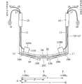
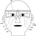
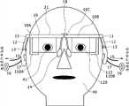
图1是从正面观看的根据本发明实施例1的头戴型显示器的示意图;1 is a schematic diagram of a head-mounted display according to Embodiment 1 of the present invention viewed from the front;
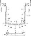
图2是从正面观看的根据实施例1的头戴型显示器(在假设框架被移除的条件下)的示意图;2 is a schematic view of the head-mounted display according to Embodiment 1 (under the assumption that the frame is removed) viewed from the front;
图3是从上方观看的根据实施例1的头戴型显示器的示意图;3 is a schematic view of the head-mounted display according to Embodiment 1 viewed from above;
图4是从上方观看的根据实施例1的头戴型显示器在佩戴于观看者头部上的状态下的示图(仅示出了图像显示装置,而省略了框架);4 is a view of the head-mounted display according to Embodiment 1 in a state of being worn on the head of the viewer viewed from above (only the image display device is shown, and the frame is omitted);
图5是根据实施例1的头戴型显示器中的图像显示装置的概念图;5 is a conceptual diagram of an image display device in a head-mounted display according to Embodiment 1;
图6是示出了构成根据实施例1的头戴型显示器的校正部的概念图;6 is a conceptual diagram showing a correction section constituting the head-mounted display according to Embodiment 1;
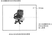
图7A和图7B每个均示出了在将实施例1的头戴型显示器佩戴在头部上时所看到的图像;7A and 7B each show an image seen when the head-mounted display of Embodiment 1 is worn on the head;
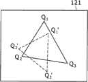
图8是用于示出实施例1的头戴型显示器中的校正原理的概念的示图;8 is a diagram for illustrating the concept of a correction principle in the head-mounted display of Embodiment 1;
图9示出了在实施例1的校正处理中通过图像生成装置而在导光板上呈现字符串的实例;FIG. 9 shows an example in which character strings are presented on the light guide plate by an image generation device in the correction process of Embodiment 1;
图10是实施例1的校正处理中的操作的流程图;FIG. 10 is a flowchart of operations in correction processing of Embodiment 1;
图11是根据本发明实施例2的头戴型显示器中的图像显示装置的概念图;11 is a conceptual diagram of an image display device in a head-mounted display according to Embodiment 2 of the present invention;
图12A和图12B分别是根据本发明实施例3的头戴型显示器中的图像显示装置的概念图,和以放大的形式示出了一部分反射型体积全息衍射光栅的示意性截面图;12A and 12B are respectively a conceptual diagram of an image display device in a head-mounted display according to Embodiment 3 of the present invention, and a schematic cross-sectional diagram showing a part of a reflective volume holographic diffraction grating in an enlarged form;
图13是根据本发明实施例4的头戴型显示器中的图像显示装置的概念图;13 is a conceptual diagram of an image display device in a head-mounted display according to Embodiment 4 of the present invention;
图14是从正面观看的根据本发明实施例5的头戴型显示器的示意图;14 is a schematic diagram of a head-mounted display according to Embodiment 5 of the present invention viewed from the front;
图15是从正面观看的根据实施例5的头戴型显示器(在假设框架被移除的条件下)的示意图;15 is a schematic view of the head-mounted display according to Embodiment 5 (under the assumption that the frame is removed) viewed from the front;
图16是从上方观看的根据实施例5的头戴型显示器的示意图;16 is a schematic diagram of a head-mounted display according to Embodiment 5 viewed from above;
图17是从正面观看的根据本发明实施例6的头戴型显示器的示意图;17 is a schematic diagram of a head-mounted display according to Embodiment 6 of the present invention viewed from the front;
图18是从正面观看的根据实施例6的头戴型显示器(在假设框架被移除的条件下)的示意图;18 is a schematic view of the head-mounted display according to Embodiment 6 viewed from the front (on the assumption that the frame is removed);
图19是从上方观看的根据实施例6的头戴型显示器的示意图;19 is a schematic diagram of a head-mounted display according to Embodiment 6 viewed from above;
图20是示出了适用于实施例1、实施例3、实施例5或实施例6的图像形成装置的修改例的概念图;20 is a conceptual diagram showing a modified example of the image forming apparatus applied to Embodiment 1, Embodiment 3, Embodiment 5, or Embodiment 6;
图21是示出了适用于实施例1、实施例3、实施例5或实施例6的图像形成装置的另一修改例的概念图;21 is a conceptual diagram showing another modified example of the image forming apparatus applied to Embodiment 1, Embodiment 3, Embodiment 5, or Embodiment 6;
图22是示出了适用于实施例1、实施例3、实施例5或实施例6的图像形成装置的又一修改例的概念图;22 is a conceptual diagram showing still another modified example of the image forming apparatus applied to Embodiment 1, Embodiment 3, Embodiment 5, or Embodiment 6;
图23是示出了适用于实施例1、实施例3、实施例5或实施例6的图像形成装置的又一修改例的概念图;以及23 is a conceptual diagram showing still another modified example of the image forming apparatus applied to Embodiment 1, Embodiment 3, Embodiment 5, or Embodiment 6; and
图24是示出了适用于实施例1、实施例3、实施例5或实施例6的图像形成装置的又一修改例的概念图;24 is a conceptual diagram showing still another modified example of the image forming apparatus applied to Embodiment 1, Embodiment 3, Embodiment 5, or Embodiment 6;
具体实施方式Detailed ways
现在,将参考附图、基于其实施例来详细描述本发明。然而,下文所述的实施例不是对本发明的限制,并且下面实施例中的各种数值和材料仅作为示例性的数值和材料而示出。顺便提及,将以下面的顺序进行描述:Now, the present invention will be described in detail based on its embodiments with reference to the accompanying drawings. However, the examples described below do not limit the present invention, and various numerical values and materials in the following examples are shown only as exemplary numerical values and materials. Incidentally, description will be made in the following order:
1、根据本发明实施方式的头戴型显示器和根据本发明实施方式的图像显示方法,概述1. The head-mounted display according to the embodiment of the present invention and the image display method according to the embodiment of the present invention, overview
2、实施例1(关于本发明的头戴型显示器和关于本发明的图像显示方法)2. Embodiment 1 (about the head-mounted display of the present invention and about the image display method of the present invention)
3、实施例2(实施例1的头戴型显示器的修改例)3. Embodiment 2 (modified example of the head-mounted display of Embodiment 1)
4、实施例3(实施例1的头戴型显示器的另一修改例)4. Embodiment 3 (another modified example of the head-mounted display of Embodiment 1)
5、实施例4(实施例1的头戴型显示器的又一修改例)5. Embodiment 4 (another modified example of the head-mounted display of Embodiment 1)
6、实施例5(实施例1的头戴型显示器的又一修改例)6. Embodiment 5 (another modified example of the head-mounted display of Embodiment 1)
7、实施例6(实施例1的头戴型显示器的又一修改例,以及其他)7. Embodiment 6 (another modified example of the head-mounted display of Embodiment 1, and others)
1、根据本发明实施方式的头戴型显示器和根据本发明实施方式的图像显示方法,概述1. The head-mounted display according to the embodiment of the present invention and the image display method according to the embodiment of the present invention, overview
在根据本发明实施方式的头戴型显示器中,优选地,校正部(校正装置)在其中存储在校准时所获得的校正数据(按照校正参数来表示,例如,以矩阵的形式),该校准用于校正由摄像装置拍摄基准对象的图像而获得的基准摄像数据,从而使通过光学装置(导光装置)观看到的基准对象的图像(该图像在下文中可称作“基准对象的真实图像”)和基于基准摄像数据而从图像生成装置输出、并在光学装置中生成的基准图像(该图像在下文中可称作“基准生成图像”)彼此重叠,并且校正部处于这样的形式,使得基于校正数据来校正摄像数据,从而使对象的真实图像和生成图像彼此重叠。In the head-mounted display according to the embodiment of the present invention, preferably, the correction section (correction means) stores therein correction data (expressed in terms of correction parameters, for example, in the form of a matrix) obtained at the time of calibration, and the calibration It is used to correct the reference imaging data obtained by taking the image of the reference object by the camera device, so that the image of the reference object viewed through the optical device (light guide device) (this image may be referred to as "the real image of the reference object" hereinafter) ) and a reference image output from the image generation device based on the reference imaging data and generated in the optical device (this image may be referred to as a "reference generated image" hereinafter) overlap each other, and the correction section is in such a form that based on the correction data to correct camera data so that the real and generated images of the subject overlap each other.
此外,在根据本发明实施方式的图像显示方法中,优选地,将通过校准(该校准用于校正基准摄像数据,从而使基准对象的真实图像和基准生成图像彼此重叠)获得的校正数据(校正参数)存储在校正部中,并且基于该校正数据来校正摄像数据,从而使对象的真实图像和生成图像彼此重叠。Furthermore, in the image display method according to the embodiment of the present invention, preferably, the correction data (corrected parameters) are stored in the correction section, and the imaging data is corrected based on the correction data so that the real image and the generated image of the subject overlap each other.
此外,以优选的形式,在校准时,校正部可以增强基准图像(基准生成图像)的至少一部分轮廓,该基准图像基于由摄像装置拍摄基准对象的图像而获得的基准摄像数据而从图像生成装置输出、并在光学装置中生成[根据本发明实施方式的头戴型显示器],或者可以通过校正部来增强至少一部分基准图像的轮廓[根据本发明实施方式的图像显示方法]。或者,以上述优选形式,在校准时,校正部可执行这样的处理,以使基于由摄像装置拍摄基准对象的图像而获得的基准摄像数据而从图像生成装置输出的、并在光学装置中生成的基准图像(基准生成图像)的颜色不同于基准对象的颜色[根据本发明实施方式的头戴型图像显示器],或者可以通过校正部使基准图像的颜色不同于基准对象的颜色[根据本发明实施方式的图像显示方法]。通过所采用的这些构成,观看者可以容易地判断基准对象的真实图像和在光学装置中生成的基准生成图像彼此是否重叠。In addition, in a preferred form, at the time of calibration, the correcting section may enhance at least a part of the outline of a reference image (reference generated image) obtained from the image generation device based on reference imaging data obtained by capturing an image of the reference object by the imaging device. output and generate in the optical device [the head-mounted display according to the embodiment of the present invention], or the outline of at least a part of the reference image can be enhanced by the correction part [the image display method according to the embodiment of the present invention]. Or, in the above preferred form, at the time of calibration, the correction unit may perform such a process that based on the reference imaging data obtained by capturing the image of the reference object by the imaging device, the output from the image generating device and generated in the optical device The color of the reference image (reference generated image) is different from the color of the reference object [head-mounted image display according to the embodiment of the present invention], or the color of the reference image may be different from the color of the reference object by the correction part [according to the present invention Image Display Method of Embodiment]. By adopting these constitutions, the viewer can easily judge whether or not the real image of the reference object and the reference generated image generated in the optical device overlap with each other.
或者,在上述优选形式中,校正数据(校正参数)可以包括距离基准数据,该距离基准数据是关于在校准时从基准对象到摄像装置的距离的数据,并且在校准摄像数据、从而使对象的真实图像和生成图像彼此重叠的时候,校正部可以进一步基于从对象到摄像装置的距离数据和距离基准数据来校正摄像数据[根据本发明实施方式的头戴型显示器],或者可以通过校正部基于关于从对象到摄像装置的距离的数据和距离基准数据来校正摄像数据[根据本发明实施方式的图像显示方法]。通过采用这样的构成,可以更准确地校正摄像数据。顺便提及,在摄像装置未配备有用于测量从对象到摄像装置的距离的装置情况下,能够通过观看者将关于在校准时从基准对象到摄像装置的距离的粗略数据(rough data)输入到校正部。Alternatively, in the preferred form described above, the correction data (correction parameters) may include distance reference data which is data on the distance from the reference object to the imaging device at the time of calibration, and is used when calibrating the imaging data so that the object's When the real image and the generated image overlap each other, the correcting section may further correct the imaging data [head-mounted display according to an embodiment of the present invention] based on the distance data from the subject to the imaging device and the distance reference data, or the correcting section may correct the imaging data based on The imaging data is corrected with respect to the data of the distance from the subject to the imaging device and the distance reference data [image display method according to an embodiment of the present invention]. By employing such a configuration, it is possible to more accurately correct imaging data. Incidentally, in the case where the camera is not equipped with a device for measuring the distance from the subject to the camera, rough data on the distance from the reference object to the camera at the time of calibration can be input into the Correction department.
或者,在以上述优选形式的根据本发明实施方式的头戴型显示器中,在校准中,校正部可以执行这样的处理,使得通过使基准摄像数据旋转、缩放以及移动,而使通过光学装置观看的基准对象的图像和基准生成图像彼此重叠。此外,在以上述优选形式的根据本发明实施方式的图像显示方法中,在校准中,通过使基准拍摄数据旋转、缩放以及移动,可以使通过光学装置观看的基准对象的图像和基准生成图像彼此重叠。具体地,能够基于仿射变换矩阵来校准基准摄像数据。Alternatively, in the head-mounted display according to the embodiment of the present invention in the preferred form described above, in the calibration, the correcting section may perform processing such that the reference imaging data is rotated, scaled, and shifted so that the image viewed through the optical device The image of the fiducial object and the fiducial generated image overlap each other. Furthermore, in the image display method according to the embodiment of the present invention in the preferred form described above, in the calibration, by rotating, scaling, and shifting the reference photographed data, the image of the reference object viewed through the optical device and the reference generated image can be made to correspond to each other. overlapping. Specifically, the reference imaging data can be calibrated based on an affine transformation matrix.
在包括上述优选形式和构成的根据本发明实施方式的头戴型显示器中,优选地,校正部执行摄像数据的旋转处理、缩放处理和移动处理。此外,在包括上述优选形式和构成的关于本发明的图像显示方法中,优选地,通过校正部执行摄像数据的旋转处理、缩放处理和移动处理。具体地,足以基于仿射变换矩阵来校准摄像数据。In the head-mounted display according to the embodiment of the present invention including the above-described preferred forms and configurations, preferably, the correction section executes rotation processing, scaling processing, and moving processing of the imaging data. Furthermore, in the image display method related to the present invention including the above-described preferred forms and configurations, preferably, rotation processing, scaling processing, and moving processing of imaging data are performed by the correcting section. Specifically, it is sufficient to calibrate the imaging data based on the affine transformation matrix.
在包括上述优选形式和构成的根据本发明实施方式的头戴型显示器中或在根据本发明实施方式的图像显示方法中的头戴型显示器中(下文中,这些将统称为“本发明中的头戴型显示器等”),校正部没有具体限制;例如,校正部可以包括CPU、校正程序存储装置(存储装置、存储器)、校正数据存储装置(存储装置、存储器)、输入图像切换开关、输入图像存储器以及VRAM(视频随机存取存储器)。这里,在包括上述优选形式和构成的根据本发明实施方式的图像显示方法中,在校准时,可以通过摄像装置来拍摄观看者动作的图像(例如,观看者手部的动作),并且可以通过校正部来分析该拍摄图像,从而将目的为使基准摄像数据旋转、缩放和移动的指示提供给校正部。顺便提及,可以通过已知的算法或软件来实现这样的操作。或者,可选地,在校准时,可以由校正部基于通过使用操作板所提供的观看者指示来执行基准摄像的旋转、缩放和移动处理。这能够使校正部关于观看者在校准时所需的操作而在图像显示器上显示具体指示、操作方法、指南等。In the head-mounted display according to the embodiment of the present invention including the above-mentioned preferred forms and configurations or in the head-mounted display in the image display method according to the embodiment of the present invention (hereinafter, these will be collectively referred to as "the head-mounted display, etc."), the correction unit is not specifically limited; for example, the correction unit may include a CPU, a correction program storage device (storage device, memory), a correction data storage device (storage device, memory), an input image switching switch, an input Image memory and VRAM (Video Random Access Memory). Here, in the image display method according to the embodiment of the present invention including the above-mentioned preferred forms and configurations, at the time of calibration, an image of the viewer's motion (for example, the motion of the viewer's hand) can be captured by an imaging device, and can be captured by The correcting unit analyzes the captured image, and provides instructions for rotating, scaling, and moving the reference captured data to the correcting unit. Incidentally, such operations can be realized by known algorithms or software. Or, alternatively, at the time of calibration, the rotation, scaling, and movement processing of the reference imaging may be performed by the correction section based on the viewer's instruction provided by using the operation panel. This enables the correction section to display specific instructions, operation methods, guidance, and the like on the image display regarding operations required by the viewer at the time of calibration.
在本发明中的头戴型显示器等中,可以仅设置一个图像显示装置(单眼型),或者可以设置两个图像显示装置(双眼型)。In the head-mounted display or the like in the present invention, only one image display device (monocular type) may be provided, or two image display devices may be provided (binocular type).
在该实施方式中的头戴型显示器等中,框架包括:前部,设置在观看者的前侧(整面);两个边撑部(temple portion),分别通过铰链安装至前部的两端,以及端盖部,分别连接至边撑部的末端部,并且该框架进一步附带有鼻垫。除缺少镜框(rim)外,框架和鼻垫的组装在结构上基本与一副普通眼镜相同。可以从用于形成普通眼镜的相同材料中(即,从金属、合金、塑料及其组合中)选择用于形成该框架的材料。In the head-mounted display or the like in this embodiment, the frame includes: a front part provided on the front side (entire surface) of the viewer; end, and the end cap portion are respectively connected to the end portion of the temple portion, and the frame is further attached with a nose pad. Aside from the lack of a rim, the frame and nose pad assembly is basically structurally the same as a normal pair of glasses. The material used to form the frame can be selected from the same materials used to form ordinary eyeglasses (ie, from metals, alloys, plastics, and combinations thereof).
此外,优选地,从头戴型显示器的更好设计或头戴型显示器的容易安装的观点看,从一个或两个图像生成装置延伸的配线(信号线、电源线等)穿过边撑部和端盖部的内部而延伸,并从端盖部的末端部延伸到外部以连接至外部电路(控制电路)。更优选地,每个图像生成装置均具有耳机部,并且从每个图像生成装置延伸的耳机配线穿过边撑部和端盖部的内部而延伸,并从端盖部的末端部延伸到耳机部。耳机部的实例包括耳塞式(inner ear type)耳机部和耳道式(canal type)耳机部。更具体地,耳机配线优选地以在耳廓(耳壳,concha)的后侧环绕的方式从端盖部的末端部延伸到耳机部。Furthermore, preferably, from the viewpoint of better design of the head-mounted display or easy installation of the head-mounted display, the wiring (signal line, power supply line, etc.) extending from one or both image generating devices passes through the temple part and the inside of the end cap part, and extends from the end part of the end cap part to the outside to be connected to an external circuit (control circuit). More preferably, each image generating device has an earphone part, and an earphone cord extending from each image generating device extends through the inside of the temple part and the end cap part, and extends from the end part of the end cap part to the headphone department. Examples of the earphone section include an inner ear type earphone section and a canal type earphone section. More specifically, the earphone wire preferably extends from the tip portion of the end cap portion to the earphone portion in such a manner as to wrap around the rear side of the auricle (concha).
在本实施方式中的头戴型显示器等中,摄像装置可以安装至前部的中央部。具体地,该摄像装置包括具有CCD(电荷耦合器件)传感器或CMOS(互补型金属氧化物半导体)传感器的固态摄像元件以及一个或多个透镜。例如,可以使从摄像装置延伸的配线通过前部的后侧从而连接至一侧的图像显示装置,并且还可以使该配线包括在从一个图像生成装置或多个图像生成装置延伸的配线中。In the head-mounted display or the like in this embodiment, the imaging device may be attached to the central portion of the front portion. Specifically, the imaging device includes a solid-state imaging element having a CCD (Charge Coupled Device) sensor or a CMOS (Complementary Metal Oxide Semiconductor) sensor, and one or more lenses. For example, it is possible to make the wiring extending from the imaging device pass through the rear side of the front so as to be connected to the image display device on one side, and it is also possible to make the wiring included in the wiring extending from one image generating device or a plurality of image generating devices. in line.
在根据本发明实施方式的头戴型显示器等中,每个光学装置均可以包括:In the head-mounted display or the like according to the embodiment of the present invention, each optical device may include:
(a)导光板,相对于图像生成装置而整体上设置在观看者脸部的中心侧,从图像生成装置发射的光束在该导光板上入射、通过该导光板来引导该光束、并且从该导光板向观看者的瞳孔发射该光束;(a) A light guide plate, which is disposed on the central side of the viewer's face as a whole with respect to the image generating device, on which a light beam emitted from the image generating device is incident, through which the light beam is guided, and from which The light guide plate emits the light beam towards the pupil of the viewer;
(b)第一偏转部,通过其而使进入导光板的光束偏转,以使进入导光板的光束在导光板内部进行全反射;以及(b) a first deflection unit, through which the light beam entering the light guide plate is deflected, so that the light beam entering the light guide plate is totally reflected inside the light guide plate; and
(c)第二偏转部,通过其使在进行全反射的同时而通过导光板的内部而传播的光束偏转多次,以使在进行全反射的同时而通过导光板的内部而传播的光束从导光板发射。顺便提及,术语“全反射”指的是内部全反射,或是在导光板内部中的全反射。这也适用于下面的描述中。(c) A second deflection section that deflects the light beam propagating through the inside of the light guide plate while undergoing total reflection by deflecting a plurality of times so that the light beam propagating through the inside of the light guide plate while undergoing total reflection goes from Light guide plate emission. Incidentally, the term "total reflection" refers to internal total reflection, or total reflection in the interior of the light guide plate. This also applies to the description below.
此外,在本发明中的头戴型显示器等的上述形式中,可以采用这样的构成,其中,第一偏转部反射进入导光板的光束,而第二偏转部多次透射和反射在进行全反射的同时而通过导光板的内部而传播的光束。在这种情况下,还可以采用其中第一偏转部用作反射镜而第二偏转部用作半透明镜的构成。Furthermore, in the above-described forms of the head-mounted display and the like in the present invention, a configuration may be adopted in which the first deflecting portion reflects the light beam entering the light guide plate, and the second deflecting portion transmits and reflects multiple times before performing total reflection. The light beam that propagates through the inside of the light guide plate at the same time. In this case, it is also possible to employ a configuration in which the first deflection section functions as a reflection mirror and the second deflection section functions as a semitransparent mirror.
在这种构成中,第一偏转部可以包括:光反射膜(一种镜),由例如金属或合金形成并反射进入导光板的光束;或者衍射光栅(例如,全息衍射光栅膜),使进入导光板的光束衍射。此外,第二偏转部可以包括在其中层压了多重介电层压膜的多层层压结构、单向透视镜(half mirror)、偏光分束器或全息衍射光栅膜。第一偏转部和第二偏转部均设置在导光板的内部(集成在导光板中)。在第一偏转部,进入导光板的平行光束被反射或衍射,以使进入导光板的平行光束在导光板的内部进行全反射。另一方面,在第二偏转部,在进行全反射的同时而通过导光板的内部而传播的平行光束被多次反射或衍射,并以平行光束的状态从导光板发射。In this configuration, the first deflecting part may include: a light reflection film (a kind of mirror) formed of, for example, metal or alloy and reflecting the light beam entering the light guide plate; or a diffraction grating (for example, a holographic diffraction grating film) that Beam diffraction by the light guide plate. In addition, the second deflection part may include a multilayer laminate structure in which multiple dielectric laminate films are laminated, a half mirror, a polarizing beam splitter, or a hologram diffraction grating film. Both the first deflection unit and the second deflection unit are disposed inside the light guide plate (integrated in the light guide plate). In the first deflecting part, the parallel light beams entering the light guide plate are reflected or diffracted, so that the parallel light beams entering the light guide plate are totally reflected inside the light guide plate. On the other hand, in the second deflection section, the parallel light beam propagating through the inside of the light guide plate while undergoing total reflection is multi-reflected or diffracted, and is emitted from the light guide plate in a parallel light beam state.
或者,可选地,在本发明中的头戴型显示器等的上述形式中,可以采用这样的构成,其中,第一偏转部衍射进入导光板的光束,而第二偏转部多次衍射在进行全反射的同时而通过导光板的内部传播的光束。此外,第一偏转部和第二偏转部每个均可以包括衍射光栅元件;在这种情况下,衍射光栅元件还可以包括反射型衍射光栅元件或透射型(transimission-type)衍射光栅元件。或者,可以采用这样的构成,其中,一侧的衍射光栅元件包括反射型衍射光栅元件,而另一侧的衍射光栅元件包括透射型衍射光栅元件。顺便提及,可以将反射型体积全息衍射光栅描述为反射型衍射光栅元件的实例。为了方便,可以将包括反射型体积全息衍射光栅的第一偏转部称作“第一衍射光栅构件”,并且为了方便,可以将包括反射型体积全息衍射光栅的第二偏转部称作“第二衍射光栅构件”。Or, alternatively, in the above forms of the head-mounted display and the like in the present invention, such a configuration may be adopted, wherein the first deflecting part diffracts the light beam entering the light guide plate, and the second deflecting part diffracts the light beam entering the light guide plate multiple times while performing multiple diffractions. The light beam propagates through the interior of the light guide plate while being totally reflected. Furthermore, each of the first deflection section and the second deflection section may include a diffraction grating element; in this case, the diffraction grating element may also include a reflection-type diffraction grating element or a transmission-type diffraction grating element. Alternatively, a configuration may be employed in which the diffraction grating element on one side includes a reflection type diffraction grating element and the diffraction grating element on the other side includes a transmission type diffraction grating element. Incidentally, a reflection type volume hologram diffraction grating can be described as an example of a reflection type diffraction grating element. For convenience, the first deflection section including the reflective volume hologram diffraction grating may be referred to as "first diffraction grating member", and for convenience, the second deflection section including the reflective volume hologram diffraction grating may be referred to as "second diffraction grating member". Diffraction Grating Components".
第一衍射光栅构件或第二衍射光栅构件可以具有这样的构成,其中,为了对应于具有不同P种波长频带(或波长)的P种光束的衍射/反射(这里,例如,P=3,以用于三种颜色,即,红色、绿色和蓝色),层压均包括反射型体积全息衍射光栅的P层衍射光栅层的各层。顺便提及,各衍射光栅层在其中形成有对应于一种波长频带(或波长)的干涉条纹。或者,可以采用这样的构成,其中,为了对应于具有不同P种波长频带(或波长)的P种光束的衍射/反射,包括一个衍射光栅层的第一衍射光栅构件或第二衍射光栅构件在其中形成有P种干涉条纹。或者,还可以采用这样的构成,其中,例如,视角被三等分,并且第一衍射光栅构件或第二衍射光栅构件具有层压了对应于这些视角的衍射光栅层的结构。当采用如上所述的构成时,对于在第一衍射光栅构件或第二衍射光栅构件衍射/反射的具有各个波长频带(或波长)的光束,能够预期提高的衍射效率、扩大的衍射受光角(acceptance angle)和最优化的衍射角。The first diffraction grating member or the second diffraction grating member may have a configuration in which, in order to correspond to the diffraction/reflection of P types of light beams having different P types of wavelength bands (or wavelengths) (here, for example, P=3, to For three colors, ie, red, green, and blue), layers of the P-layer diffraction grating layer each including a reflective volume hologram diffraction grating are laminated. Incidentally, each diffraction grating layer has formed therein interference fringes corresponding to one wavelength band (or wavelength). Alternatively, a configuration may be adopted in which, in order to correspond to the diffraction/reflection of P types of light beams having different P types of wavelength bands (or wavelengths), the first diffraction grating member or the second diffraction grating member including one diffraction grating layer is P types of interference fringes are formed therein. Alternatively, it is also possible to employ a configuration in which, for example, viewing angles are divided into thirds, and the first diffraction grating member or the second diffraction grating member has a structure in which diffraction grating layers corresponding to these viewing angles are laminated. When adopting the composition as described above, for light beams having respective wavelength bands (or wavelengths) diffracted/reflected at the first diffraction grating member or the second diffraction grating member, it is possible to expect improved diffraction efficiency, expanded diffraction acceptance angle ( acceptance angle) and the optimized diffraction angle.
作为用于构成第一衍射光栅构件和第二衍射光栅构件的材料,可以提及光敏聚合物材料。均包括反射型体积全息衍射光栅的第一衍射光栅构件和第二衍射光栅构件的构成材料和基本结构可以与根据现有技术的反射型体积全息衍射光栅的构成材料和基本结构相同。该反射型体积全息衍射光栅指的是仅执行+1(加1)次衍射的光束的衍射/反射的全息衍射光栅。衍射光栅构件在从其内部到其表面范围的部分中形成有干涉条纹,并且用于形成干涉条纹本身的方法可以与现有技术中的形成方法相同。具体地,可以采用这样的方法,其中,例如,在一侧用来自第一预定方向的对象光束照射构成衍射光栅构件的构件(例如,光敏聚合物材料),同时,在另一侧用来自第二预定方向的基准光束照射构成衍射光栅构件的构件,从而将通过对象光束和基准光束形成的干涉条纹记录在构成衍射光栅构件的构件的内部。当适当地选择第一预定方向、第二预定方向以及对象光束和基准光束的波长时,能够获得相对于衍射光栅构件表面上的干涉条纹的所需间距和所需斜角。干涉条纹的斜角指的是在衍射光栅构件(或衍射光栅层)的表面与干涉条纹之间形成的角度。在第一衍射光栅构件和第二衍射光栅构件均具有P层衍射光栅层(每一层均包括反射型体积全息衍射光栅)的层压结构的情况下,可以通过单独形成P层衍射光栅层并且之后通过使用例如UV固化粘合剂将P层衍射光栅层彼此层压(粘附)在其上,来执行这种衍射光栅层的层压。或者,可选地,可以采用这样的方法,其中,通过使用粘性光聚合物材料形成一个衍射光栅层,并且之后通过连续粘附粘性光聚合物材料而在其上形成多个衍射光栅层,从而制造P层衍射光栅层。As a material for constituting the first diffraction grating member and the second diffraction grating member, a photosensitive polymer material can be mentioned. The constituent materials and basic structure of the first and second diffraction grating members each including a reflective volume hologram diffraction grating may be the same as those of the reflective volume hologram diffraction grating according to the prior art. The reflective volume hologram diffraction grating refers to a hologram diffraction grating that performs only diffraction/reflection of a light beam diffracted in +1 (plus 1) order. The diffraction grating member is formed with interference fringes in a portion ranging from its inside to its surface, and the method for forming the interference fringes itself may be the same as that in the prior art. Specifically, a method may be employed in which, for example, a member (for example, a photosensitive polymer material) constituting the diffraction grating member is irradiated on one side with an object light beam from a first predetermined direction, and at the same time, is illuminated on the other side with light from a second direction. The reference beams in two predetermined directions irradiate the members constituting the diffraction grating member, thereby recording interference fringes formed by the subject beams and the reference beams inside the members constituting the diffraction grating member. When the first predetermined direction, the second predetermined direction, and the wavelengths of the object beam and the reference beam are appropriately selected, a desired pitch and a desired off-angle with respect to interference fringes on the surface of the diffraction grating member can be obtained. The oblique angle of the interference fringes refers to the angle formed between the surface of the diffraction grating member (or the diffraction grating layer) and the interference fringes. In the case where the first diffraction grating member and the second diffraction grating member each have a laminated structure of P-layer diffraction grating layers (each layer including a reflective volume hologram diffraction grating), it is possible to form the P-layer diffraction grating layer separately and Lamination of such a diffraction grating layer is then performed by laminating (adhering) the P-layer diffraction grating layers to each other using, for example, a UV-curable adhesive. Alternatively, a method may be employed in which one diffraction grating layer is formed by using an adhesive photopolymer material, and then a plurality of diffraction grating layers are formed thereon by successively adhering the adhesive photopolymer material, thereby Fabricate the p-layer diffraction grating layer.
或者,在本发明中的头戴型显示器等中,每个光学装置可以均包括相对于图像生成装置而设置在观看者脸部中心侧的半透明镜,从图像生成装置发射的光束在该半透明镜上入射、并且从该半透明镜向观看者的瞳孔发射该光束。顺便提及,从图像生成装置发射的光束可以通过空气传播以在半透明镜上入射,或者可以通过诸如玻璃板或塑料板的透明构件(具体地,由与构成下文将描述的导光板的材料相类似的材料形成的构件)的内部传播以在半透明镜上入射。顺便提及,可以通过透明构件将半透明镜安装至图像生成装置;可选地,可以通过除透明构件以外的构件将半透明镜安装至图像生成装置。Alternatively, in the head-mounted display or the like in the present invention, each optical device may include a semi-transparent mirror provided on the central side of the viewer's face with respect to the image generating device, and the light beam emitted from the image generating device passes through the semi-transparent mirror. The light beam is incident on a transparent mirror and is emitted from the semi-transparent mirror to the pupil of the viewer. Incidentally, the light beam emitted from the image generating device may propagate through air to be incident on a semi-transparent mirror, or may pass through a transparent member such as a glass plate or a plastic plate (specifically, made of a material constituting a light guide plate to be described later). components formed of similar materials) to be incident on the semi-transparent mirror. Incidentally, the semi-transparent mirror may be attached to the image generating device through a transparent member; alternatively, the semi-transparent mirror may be attached to the image generating device through a member other than the transparent member.
在包括上述各种优选形式和构成的根据本发明实施方式的头戴型显示器等中,图像生成装置可以包括:In the head-mounted display or the like according to the embodiments of the present invention including the various preferred forms and configurations described above, the image generating device may include:
(a)图像形成装置,具有以二维矩阵构成的多个像素;以及(a) an image forming device having a plurality of pixels configured in a two-dimensional matrix; and
(b)准直光学系统,通过其而将从图像形成装置的像素发射的光束变成平行光束并发射该平行光束。顺便提及,为方便起见,如上所述的图像生成装置的构成将被称作“第一构成的图像生成装置”。(b) A collimating optical system by which light beams emitted from pixels of the image forming device are turned into parallel light beams and the parallel light beams are emitted. Incidentally, for the sake of convenience, the configuration of the image generating device as described above will be referred to as "the image generating device of the first configuration".
在第一构成的图像生成装置中,图像形成装置的实例包括:包括反射型空间光调制器和光源的图像形成装置;包括透射型空间光调制器和光源的图像形成装置;以及包括诸如有机EL(电致发光)元件、无机EL元件、发光二极管(LED)等发光元件的图像形成装置。在这些图像形成装置中,优选的是包括反射型空间光调制器和光源的图像形成装置。空间光调制器的实例包括光阀,例如,诸如LCOS(硅上液晶)等的透射型或反射型液晶显示装置、数字微镜装置(DMD)等。光源的实例包括发光元件。此外,反射型空间光调制器可以包括液晶显示装置和偏光分束器,来自光源的一部分光束被该偏光分束器反射并被引导至液晶显示装置,并且由液晶显示装置反射的一部分光束透射通过该偏光分束器并被引导至准直光学系统。用于构成光源的发光元件的实例包括红色发光元件、绿色发光元件、蓝色发光元件以及白色发光元件。此外,发光元件的实例包括半导体激光元件和LED。可以基于头戴型显示器所需的规格来确定像素数目。像素数目的实例包括320×240、432×240、640×480、1024×768和1920×1080。In the image generating device of the first configuration, examples of the image forming device include: an image forming device including a reflective spatial light modulator and a light source; an image forming device including a transmissive spatial light modulator and a light source; Image forming apparatuses for light-emitting elements such as (electroluminescent) elements, inorganic EL elements, and light-emitting diodes (LEDs). Among these image forming devices, an image forming device including a reflective spatial light modulator and a light source is preferred. Examples of spatial light modulators include light valves, for example, transmissive or reflective liquid crystal display devices such as LCOS (Liquid Crystal on Silicon), digital micromirror devices (DMDs), and the like. Examples of light sources include light emitting elements. In addition, the reflective spatial light modulator may include a liquid crystal display device and a polarizing beam splitter by which a part of the light beam from the light source is reflected and guided to the liquid crystal display device, and a part of the light beam reflected by the liquid crystal display device is transmitted through The polarizing beam splitter is directed to a collimating optics system. Examples of light emitting elements for constituting a light source include red light emitting elements, green light emitting elements, blue light emitting elements, and white light emitting elements. In addition, examples of light emitting elements include semiconductor laser elements and LEDs. The number of pixels may be determined based on specifications required for the head mounted display. Examples of the number of pixels include 320×240, 432×240, 640×480, 1024×768, and 1920×1080.
或者,在包括上述优选形式和构成的根据本发明另一实施方式的头戴型显示器中,图像生成装置可以包括:Alternatively, in the head-mounted display according to another embodiment of the present invention including the above-mentioned preferred forms and configurations, the image generation device may include:
(a)光源;(a) a light source;
(b)准直光学系统,通过其将从光源发射的光束变成平行光束;(b) a collimating optical system by which the light beam emitted from the light source is changed into a parallel light beam;
(c)扫描部,被构成为扫描从准直光学系统发射的平行光束;以及(c) a scanning section configured to scan the parallel light beam emitted from the collimating optical system; and
(d)中继光学系统,通过其来中继和发射由扫描部扫描的平行光束。顺便提及,为方便起见,如上所述的图像生成装置的构成将被称作“第二构成的图像生成装置”。(d) A relay optical system through which the parallel beams scanned by the scanning section are relayed and emitted. Incidentally, for the sake of convenience, the configuration of the image generating device as described above will be referred to as "the image generating device of the second configuration".
例如,第二构成的图像生成装置中的光源例如可以包括一个或多个发光元件。一个或多个发光元件的具体实例包括红色发光元件、绿色发光元件、蓝色发光元件和白色发光元件。此外,发光元件的实例包括半导体激光元件和LED。也可以基于头戴型显示器所需的规格来确定第二构成的图像生成装置中的像素(虚拟像素)数目。像素(虚拟像素)数目的具体实例包括320×240、432×240、640×480、1024×768和1920×1080。此外,在通过使用红色发光元件、绿色发光元件和蓝色发光元件来组成光源的情况下,例如,通过使用例如正交棱镜来执行颜色合成是优选的。扫描部的实例包括使从光源发射的光束进行水平扫描和垂直扫描的部件,例如,具有能够以二维方向旋转的微镜或电流镜(galvano-mirror)的MEMS(微型机电系统)。中继光学系统可以包括已知的中继光学系统。For example, the light source in the image generating device of the second configuration may include, for example, one or more light emitting elements. Specific examples of the one or more light emitting elements include red light emitting elements, green light emitting elements, blue light emitting elements, and white light emitting elements. In addition, examples of light emitting elements include semiconductor laser elements and LEDs. The number of pixels (virtual pixels) in the image generating device of the second configuration may also be determined based on the specifications required for the head-mounted display. Specific examples of the number of pixels (virtual pixels) include 320×240, 432×240, 640×480, 1024×768, and 1920×1080. Furthermore, in the case of composing a light source by using red light emitting elements, green light emitting elements, and blue light emitting elements, for example, it is preferable to perform color synthesis by using, for example, a cross prism. Examples of the scanning section include components that horizontally and vertically scan light beams emitted from a light source, such as MEMS (Micro Electro Mechanical Systems) having micromirrors or galvano-mirrors that can rotate in two-dimensional directions. The relay optics may include known relay optics.
例如,可以使用包括发光元件和光阀的图像形成装置。或者,可以使用可用于整体上发射白光作为光源的背光与具有红色发光像素、绿色发光像素和蓝色发光像素的液晶显示装置的组合。除上述构成外,也可以将下面的构成提及为可用构成的实例。For example, an image forming device including a light emitting element and a light valve can be used. Alternatively, a combination of a backlight capable of emitting white light as a light source as a whole and a liquid crystal display device having red, green, and blue light-emitting pixels may be used. In addition to the above-mentioned constitutions, the following constitutions can also be mentioned as examples of usable constitutions.
图像形成装置AImage forming device A
图像形成装置A包括:Image forming apparatus A includes:
(α)第一图像形成装置,具有以二维矩阵形式配置可用于发射蓝光的第一发光元件的第一发光板;(α) a first image forming device having a first light-emitting panel in which first light-emitting elements capable of emitting blue light are arranged in a two-dimensional matrix;
(β)第二图像形成装置,具有以二维矩阵形式配置可用于发射绿光的第二发光元件的第二发光板;和(β) a second image forming device having a second light-emitting panel in which second light-emitting elements capable of emitting green light are arranged in a two-dimensional matrix; and
(γ)第三图像形成装置,具有以二维矩阵形式配置可用于发射红光的第三发光元件的第三发光板;以及(γ) a third image forming device having a third light-emitting panel in which third light-emitting elements capable of emitting red light are arranged in a two-dimensional matrix; and
(δ)被构成为将从第一图像形成装置、第二图像形成装置和第三图像形成装置发射的光集中到单个光路中的部件(该部件例如是二向棱镜,在下面的描述中也有相同应用);(δ) is constituted as a member that concentrates the light emitted from the first image forming means, the second image forming means, and the third image forming means into a single optical path (the member is, for example, a dichroic prism, also in the following description same application);
其中,第一发光元件、第二发光元件和第三发光元件的发光/非发光状态受控。Wherein, the light-emitting/non-light-emitting states of the first light-emitting element, the second light-emitting element and the third light-emitting element are controlled.
图像形成装置Bimage forming device B
图像形成装置B包括:Image forming apparatus B includes:
(α)第一图像形成装置,包括:第一发光元件,可用于发射蓝光;和第一光通过(passage)控制器,被构成为控制从可用于发射蓝光的第一发光元件发射的光的通过/非通过[光通过控制器是一种光阀,并且例如包括液晶显示装置、数字微镜装置(DMD)或LCOS,在下面的描述中也有相同应用];(α) A first image forming device comprising: a first light emitting element operable to emit blue light; and a first light passage controller configured to control the passage of light emitted from the first light emitting element operable to emit blue light pass/no pass [the light pass controller is a kind of light valve and includes for example liquid crystal display devices, digital micromirror devices (DMD) or LCOS, the same applies in the description below];
(β)第二图像形成装置,包括:第二发光元件,可用于发射绿光;以及第二光通过控制器(光阀),被构成为控制从可用于发射绿光的第二发光元件发射的光的通过/非通过;和(β) A second image forming device comprising: a second light emitting element operable to emit green light; and a second light passing controller (light valve) configured to control emission from the second light emitting element operable to emit green light pass/non-pass of light; and
(γ)第三图像形成装置,包括:第三发光元件,可用于发射红光;以及第三光通过控制器(光阀),被构成为控制从可用于发射红光的第三发光元件发射的光的通过/非通过;以及(γ) A third image forming device comprising: a third light emitting element operable to emit red light; and a third light passing controller (light valve) configured to control emission from the third light emitting element operable to emit red light pass/non-pass of light; and
(δ)被构成为将通过第一光通过控制器、第二光通过控制器和第三光通过控制器的光集中到单个光路中的部件;(δ) a component configured to concentrate light passing through the first light pass controller, the second light pass controller, and the third light pass controller into a single light path;
其中,由光通过控制器来控制从发光元件发射的光的通过/非通过,从而显示图像。被构成为将从第一发光元件、第二发光元件和第三发光元件发射的光引导至光通过控制器的部件(导光构件)的实例包括导光构件、微透镜阵列、反射镜或反射板以及聚光透镜。Among them, the pass/non-pass of the light emitted from the light emitting element is controlled by the light pass controller, thereby displaying an image. Examples of the member (light guide member) configured to guide the light emitted from the first light emitting element, the second light emitting element, and the third light emitting element to the light passing controller include a light guide member, a microlens array, a mirror, or a reflector. plate and condenser lens.
图像形成装置CImage forming device C
图像形成装置C包括:The image forming device C includes:
(α)第一图像形成装置,包括:第一发光板,其中以二维矩阵形式配置可用于发射蓝光的第一发光元件;以及蓝光通过控制器(光阀),被构成为控制从第一发光板发射的光的通过/非通过;(α) A first image forming device comprising: a first light emitting panel in which first light emitting elements capable of emitting blue light are arranged in a two-dimensional matrix; and a blue light passing controller (light valve) configured to control Pass/non-pass of the light emitted by the luminous panel;
(β)第二图像形成装置,包括:第二发光板,其中以二维矩阵形式配置可用于发射绿光的第二发光元件;以及绿光通过控制器(光阀),被构成为控制从第二发光板发射的光的通过/非通过;和(β) A second image forming device comprising: a second light emitting panel in which second light emitting elements usable for emitting green light are arranged in a two-dimensional matrix; and a green light passing controller (light valve) configured to control pass/non-pass of light emitted by the second luminous panel; and
(γ)第三图像形成装置,包括:第三发光板,其中以二维矩阵形式配置可用于发射红光的第三发光元件;以及红光通过控制器(光阀),被构成为控制从第三发光板发射的光的通过/非通过;以及(γ) A third image forming device comprising: a third light emitting panel in which third light emitting elements usable for emitting red light are arranged in a two-dimensional matrix; and a red light passing controller (light valve) configured to control pass/non-pass of light emitted by the third luminous panel; and
(δ)被构成为将通过蓝光通过控制器、绿光通过控制器和红光通过控制器的光集中到单个光路中的部件;(δ) a component configured to concentrate the light passing through the blue pass controller, the green pass controller and the red pass controller into a single optical path;
其中,由光通过控制器(光阀)来控制从第一发光板、第二发光板和第三发光板发射的光的通过/非通过,从而显示图像。Among them, passing/non-passing of light emitted from the first light emitting panel, the second light emitting panel and the third light emitting panel is controlled by a light passing controller (light valve), thereby displaying an image.
图像形成装置DImage forming device D
图像形成装置D,其为用于场序制系统(field sequential system)的彩色显示器,包括:An image forming device D, which is a color display for a field sequential system (field sequential system), includes:
(α)第一图像形成装置,具有可用于发射蓝光的第一发光元件;(α) a first image forming device having a first light emitting element operable to emit blue light;
(β)第二图像形成装置,具有可用于发射绿光的第二发光元件;和(β) a second image forming device having a second light emitting element operable to emit green light; and
(γ)第三图像形成装置,具有可用于发射红光的第三发光元件;以及(γ) a third image forming device having a third light emitting element operable to emit red light; and
(δ)被构成为将从第一图像形成装置、第二图像形成装置和第三图像形成装置发射的光集中到单个光路中的部件;并且还包括:(δ) a member configured to concentrate light emitted from the first image forming device, the second image forming device, and the third image forming device into a single optical path; and further comprising:
(ε)光通过控制器(光阀),被构成为控制从被构成为将光集中到单个光路中的部件发射的光的通过/非通过。(ε) Light passing controller (light valve) configured to control passage/non-passage of light emitted from a member configured to concentrate light into a single optical path.
其中,由光通过控制器来控制从发光元件发射的光的通过/非通过,从而显示图像。Among them, the pass/non-pass of the light emitted from the light emitting element is controlled by the light pass controller, thereby displaying an image.
图像形成装置EImage forming device E
图像形成装置E,其也是用于场序制系统的彩色显示器,包括:Image forming apparatus E, which is also a color display for a field sequential system, comprising:
(α)第一图像形成装置,具有以二维矩阵形式配置可用于发射蓝光的第一发光元件的第一发光板;(α) a first image forming device having a first light-emitting panel in which first light-emitting elements capable of emitting blue light are arranged in a two-dimensional matrix;
(β)第二图像形成装置,具有以二维矩阵形式配置可用于发射绿光的第二发光元件的第二发光板;和(β) a second image forming device having a second light-emitting panel in which second light-emitting elements capable of emitting green light are arranged in a two-dimensional matrix; and
(γ)第三图像形成装置,具有以二维矩阵形式配置可用于发射红光的第三发光元件的第三发光板;以及(γ) a third image forming device having a third light-emitting panel in which third light-emitting elements capable of emitting red light are arranged in a two-dimensional matrix; and
(δ)被构成为将分别从第一图像形成装置、第二图像形成装置和第三图像形成装置发射的光集中到单个光路中的部件;并且还包括:(δ) is constituted as a component that collects light respectively emitted from the first image forming device, the second image forming device, and the third image forming device into a single optical path; and further includes:
(ε)光通过控制器(光阀),被构成为控制从被构成为将光集中到单个光路中的部件发射的光的通过/非通过。(ε) Light passing controller (light valve) configured to control passage/non-passage of light emitted from a member configured to concentrate light into a single optical path.
其中,由光通过控制器来控制从发光板发射的光的通过/非通过,从而显示图像。Wherein, the pass/non-pass of the light emitted from the light emitting panel is controlled by the light pass controller, thereby displaying images.
图像形成装置FImage forming device F
图像形成装置F是用于无源矩阵型或有源矩阵型彩色显示器的图像形成装置,其中,通过控制第一发光元件、第二发光元件和第三发光元件各自的发光/非发光状态来显示图像。The image forming device F is an image forming device for a passive matrix type or an active matrix type color display, in which display image.
图像形成装置GImage forming device G
图像形成装置G,其为用于场序制系统的彩色显示器的图像形成装置,包括光通过控制器(光阀),其被构成为控制从以二维矩阵形式配置的发光元件单元发射的光的通过/非通过,其中,基于时分来控制发光元件单元中的第一发光元件、第二发光元件和第三发光元件的各自的发光/非发光状态,此外,由光通过控制器来控制从第一发光元件、第二发光元件和第三发光元件发射的光的通过/非通过,从而显示图像。Image forming apparatus G, which is an image forming apparatus for a color display of a field sequential system, includes a light passing controller (light valve) configured to control light emitted from light emitting element units arranged in a two-dimensional matrix form pass/non-pass, wherein the respective light-emitting/non-light-emitting states of the first light-emitting element, the second light-emitting element, and the third light-emitting element in the light-emitting element unit are controlled based on time division, and in addition, the light-passing controller is controlled from The pass/non-pass of the light emitted by the first light emitting element, the second light emitting element and the third light emitting element displays an image.
在第一构成的图像生成装置或第二构成的图像生成装置中,使通过准直光学系统成为多个平行光束的光束在导光板上入射。在这种情况下,光束成为平行光束的要求基于以下要求:即使光束在通过第一偏转部和第二偏转部的功能而从导光板发射之后,也应保存关于该光束在导光板上入射时的光波阵面(light wave fronts)的信息。顺便提及,具体地,可以通过其中图像形成装置例如位于准直光学系统的焦距处(位置)的构成来生成多个平行光束,该准直光学系统具有将关于像素位置的信息转换为关于在光学装置的光学系统中的角度的信息的功能。作为准直光学系统的实例,可以提及这样的光学系统,其中,可以单独使用凸透镜、凹透镜、自由形态平面棱镜和全息透镜中的任一种或者或组合使用上述透镜,以使该系统整体上具有正光学倍率(positive optical power)。In the image generating device of the first configuration or the image generating device of the second configuration, the light beams converted into a plurality of parallel light beams by the collimating optical system are made incident on the light guide plate. In this case, the requirement for the light beam to be a parallel light beam is based on the requirement that even after the light beam is emitted from the light guide plate by the functions of the first deflecting part and the second deflecting part, the information about when the light beam is incident on the light guide plate should be preserved. Information about the light wave fronts. Incidentally, specifically, a plurality of parallel light beams can be generated by a configuration in which an image forming device is located, for example, at a focal length (position) of a collimating optical system having the function of converting information on a pixel position into information on a position at The function of angular information in the optical system of an optical device. As an example of a collimating optical system, there can be mentioned an optical system in which any one of a convex lens, a concave lens, a free-form plane prism, and a holographic lens can be used alone or in combination, so that the system as a whole Has positive optical power.
导光板具有平行于导光板的轴线(Y-方向)而延伸的两个平行表面(第一表面和第二表面)。在光束入射的导光板表面被称作导光板入射表面、并且在光束从导光板发射的导光板表面被称作导光板发射表面的情况下,导光板入射表面和导光板发射表面均可由第一表面组成。或者,可选地,可以采用这样的构成,其中,导光板入射表面由第一表面组成,而导光板发射表面由第二表面组成。构成导光板材料的实例包括包含诸如熔凝石英、BK7等光学玻璃的玻璃和塑料材料(例如,PMMA(聚甲基丙烯酸甲酯)、聚碳酸酯树脂、丙烯酸树脂、无定形聚丙烯树脂、包含AS树脂(丙烯腈苯乙烯共聚物)的聚苯乙烯树脂)。导光板的形状不限于平板状,而也可以是弯曲状。The light guide plate has two parallel surfaces (first surface and second surface) extending parallel to the axis (Y-direction) of the light guide plate. In the case where the surface of the light guide plate on which the light beam is incident is referred to as the light guide plate incident surface, and where the surface of the light guide plate on which the light beam is emitted from the light guide plate is referred to as the light guide plate emission surface, both the light guide plate incident surface and the light guide plate emission surface can be defined by the first surface composition. Or, alternatively, a configuration may be adopted in which the incident surface of the light guide plate is composed of the first surface, and the emission surface of the light guide plate is composed of the second surface. Examples of materials constituting the light guide plate include glass including optical glass such as fused silica, BK7, and plastic materials (for example, PMMA (polymethyl methacrylate), polycarbonate resin, acrylic resin, amorphous polypropylene resin, including AS resin (polystyrene resin of acrylonitrile styrene copolymer). The shape of the light guide plate is not limited to a flat shape, but may be curved.
在实施方式中的头戴型显示器等为双眼型的情况下,优选地,In the case where the head-mounted display or the like in the embodiment is a binocular type, preferably,
光学装置整体上相对于图像生成装置而设置在观看者脸部的中心侧;The optical device is disposed on the central side of the viewer's face with respect to the image generating device as a whole;
还设置了用于互相连接两个图像显示装置的连接构件;A connecting member for interconnecting two image display devices is also provided;
该连接构件安装至位于观看者的两个瞳孔之间的框架的中央部分的面向观看者侧;以及The connecting member is mounted to the viewer-facing side of the central portion of the frame between the two pupils of the viewer; and
该连接构件的投影图像包括在框架的投影图像中。The projected image of the connecting member is included in the projected image of the frame.
因此,采用了其中连接构件连接至位于观看者两个瞳孔之间的框架中央部分的结构。换而言之,这里没有采用图像显示装置直接连接至框架的结构。这确保了:即使在将框架佩戴至观看者头部时向外扩展边撑部而导致框架变形,这种框架的变形也不会引起图像生成装置或光学装置的位移(位置变化),或者,即使有的话,也只会引起非常小的这种位移。因此,可以安全地防止左图像和右图像的会聚角(辐辏角)变化。此外,由于不需要增强框架的前部的刚性,因此能够避免引起框架重量的增加、设计质量的降低或成本的提升。此外,由于图像显示装置不直接连接至眼镜框型框架,因此可以根据观看者的品位来自由选择框架的设计、颜色等;因此,几乎不存在强加于框架设计上的限制,从而基于设计的自由度非常高。此外,在观看者与框架之间设置有连接构件,并且此外,连接构件的投影图像包括在框架的投影图像中。换而言之,当从观看者的正面观看头戴型显示器时,连接构件隐藏在框架的后面。因此,头戴型显示器可以具备高的设计质量。Therefore, a structure is adopted in which the connection member is connected to the central portion of the frame located between the two pupils of the viewer. In other words, there is no structure in which the image display device is directly connected to the frame. This ensures that even if the frame is deformed by expanding the temple portion outward when the frame is worn on the viewer's head, such deformation of the frame does not cause displacement (position change) of the image generating device or the optical device, or, Only very small, if any, such displacements are induced. Therefore, it is possible to safely prevent the angle of convergence (angle of convergence) of the left image and the right image from changing. Furthermore, since there is no need to reinforce the rigidity of the front portion of the frame, it is possible to avoid causing an increase in frame weight, a reduction in design quality, or an increase in cost. In addition, since the image display device is not directly connected to the spectacle-rim type frame, the design, color, etc. of the frame can be freely selected according to the viewer's taste; The degree is very high. Furthermore, a connecting member is provided between the viewer and the frame, and furthermore, a projected image of the connecting member is included in the projected image of the frame. In other words, when the head-mounted display is viewed from the front of the viewer, the connection members are hidden behind the frame. Therefore, the head-mounted display can have high design quality.
顺便提及,连接构件优选地被构成为使得其连接至位于观看者两个瞳孔之间的前部的中央部分(该部分对应于一副普通眼镜的鼻梁架部)的面向观看者侧。Incidentally, the connection member is preferably configured such that it is connected to the viewer-facing side of a central portion of the front between the two pupils of the viewer (this portion corresponds to the bridge portion of a pair of ordinary glasses).
在头戴型显示器中,两个图像显示器通过连接构件彼此相连接。具体地,可以采用其中图像生成装置分别安装至连接构件的两端从而使得可以调节佩戴条件的构成。在这种情况下,每个图像生成装置均位于相对于观看者瞳孔的外侧。此外,在这样的构成中,期望0.01×L≤α≤0.30×L的条件,优选地,为0.05×L≤α≤0.25×L;0.35×L≤β≤0.65×L的条件,优选地,为0.45×L≤β≤0.55×L;以及0.70×L≤γ≤0.99×L的条件,优选地,为0.75×L≤γ≤0.95×L,其中,α是一侧的图像生成装置的安装部中心与框架的一个端部(在该一侧的末端件,endpiece)之间的距离,β是从连接构件的中心到框架的一个端部(在该一侧的末端件)的距离,γ是在另一侧的图像生成装置的安装部中心与框架的一个端部(在该一侧的末端件)之间的距离,以及L为框架的长度。例如,具体如下来执行图像生成装置分别到连接构件的两端部的安装。连接构件在其每个端部中的三个位置处具有通孔,而每个图像生成装置均设置有与这些通孔相对应的螺丝配合部。小螺丝分别通过通孔,并且与图像生成装置的螺丝配合部进行螺丝配合。在每个螺丝与相应的螺丝配合部之间插入弹簧。这确保了可以通过调节每个小螺丝的紧固条件来调整图像生成装置的安装条件(图像生成装置相对于连接构件的倾斜)。In the head-mounted display, two image displays are connected to each other by a connecting member. Specifically, a configuration may be employed in which image generating devices are respectively attached to both ends of the connection member so that the wearing condition can be adjusted. In this case, each image generating device is located on the outside with respect to the pupil of the viewer. In addition, in such a configuration, the condition of 0.01×L≤α≤0.30×L is desired, preferably, 0.05×L≤α≤0.25×L; the condition of 0.35×L≤β≤0.65×L, preferably, 0.45×L≤β≤0.55×L; and the condition of 0.70×L≤γ≤0.99×L, preferably, 0.75×L≤γ≤0.95×L, where α is the installation of the image generating device on one side The distance between the center of the frame and one end of the frame (the end piece on this side, endpiece), β is the distance from the center of the connecting member to one end of the frame (the end piece on this side), γ is the distance between the center of the mounting part of the image generating device on the other side and one end of the frame (the end piece on that side), and L is the length of the frame. For example, the attachment of the image generating device to both end portions of the connecting member respectively is performed specifically as follows. The connection member has through holes at three positions in each end thereof, and each image generating device is provided with screw fitting portions corresponding to these through holes. The small screws respectively pass through the through holes, and are screw-fitted with the screw fitting part of the image generating device. A spring is inserted between each screw and the corresponding screw fitting. This ensures that the installation condition of the image generating device (inclination of the image generating device relative to the connecting member) can be adjusted by adjusting the fastening condition of each small screw.
这里,表述“图像生成装置的安装部中心”表示重叠区域沿着框架轴线方向的二等分点(中点),在该重叠区域中,在图像生成装置安装至连接构件的条件下将图像生成装置和框架投影到虚拟平面上时所获得的图像生成装置的投影图像与框架的投影图像相重叠。此外,表述“连接构件的中心”表示在连接构件安装至框架的条件下连接构件与框架相接触的区域沿着框架轴线方向的二等分点(中点)。表述“框架的长度”是在框架被弯曲的情况下的框架的投影图像的长度。顺便提及,这里的投影方向为垂直于观看者脸部的方向。Here, the expression "the center of the mounting part of the image generating device" means the bisecting point (midpoint) along the frame axis direction of the overlapping area in which the image is generated under the condition that the image generating device is mounted to the connecting member. The image generated when the device and the frame are projected onto the virtual plane is superimposed on the projected image of the device and the projected image of the frame. In addition, the expression "the center of the connecting member" means a bisecting point (midpoint) along the frame axis direction of an area where the connecting member is in contact with the frame under the condition that the connecting member is mounted to the frame. The expression "length of the frame" is the length of the projected image of the frame in case the frame is bent. Incidentally, the projection direction here is a direction perpendicular to the viewer's face.
或者,在头戴型显示器中,两个图像显示装置通过连接构件彼此相连接。在这种情况下,具体地,也可以采用其中两个光学装置通过连接构件彼此相连接的形式。顺便提及,两个光学装置有时可以整体地形成,并且,在这种情况下,连接构件连接到这样整体形成的光学装置。而且,该形态包括在连接构件用于两个光学装置之间的连接的形式中。在一侧的图像生成装置的中心与框架的一个端部之间的距离是α′,并且在另一侧的图像生成装置的中心与框架的该一个端部之间的距离是γ′,α′和γ′的值也可以按照与α和γ的值相同的方式来合理地设定。顺便提及,表述“图像生成装置的中心”表示如下区域沿框架的轴线方向的二等分点,在该区域中,在图像生成装置安装至连接构件的条件下将图像生成装置和框架投影到虚拟平面上时所获得的图像生成装置的投影图像与框架的投影图像相重叠。Alternatively, in a head-mounted display, two image display devices are connected to each other through a connection member. In this case, specifically, a form in which two optical devices are connected to each other by a connecting member may also be employed. Incidentally, two optical devices may sometimes be integrally formed, and, in this case, a connecting member is connected to such integrally formed optical devices. Also, this form is included in the form in which the connection member is used for connection between two optical devices. The distance between the center of the image generating device on one side and one end of the frame is α', and the distance between the center of the image generating device on the other side and the one end of the frame is γ', α The values of ' and γ' can also be suitably set in the same manner as the values of α and γ. Incidentally, the expression "the center of the image generating device" means a bisecting point along the axis direction of the frame of an area in which the image generating device and the frame are projected on the condition that the image generating device is attached to the connecting member The projected image of the image generating device obtained while on the virtual plane is superimposed on the projected image of the frame.
在头戴型显示器中,构成框架的材料可以与用于一副普通眼镜的材料相同,诸如金属、合金、塑料及其组合。连接构件的形状基本上是可自由设定的,只要连接构件的投影图像包括在框架的投影图像中;形状的实例包括条状形状和带状形状。而且,用于形成连接构件的材料的实例包括金属、合金、塑料及其组合。另外,鼻垫可以具有任一种已知的构成或结构。In a head-mounted display, the frame may be made of the same material as that used for a normal pair of glasses, such as metal, alloy, plastic, and combinations thereof. The shape of the connecting member is basically freely settable as long as the projected image of the connecting member is included in the projected image of the frame; examples of the shape include a strip shape and a strip shape. Also, examples of materials used to form the connection members include metals, alloys, plastics, and combinations thereof. Additionally, the nose pads may have any known composition or structure.
2、实施例12. Embodiment 1
实施例1涉及根据本发明实施方式的头戴型显示器和根据本发明实施方式的图像显示方法。Example 1 relates to a head-mounted display according to an embodiment of the present invention and an image display method according to an embodiment of the present invention.
实施例1涉及根据本发明实施方式的头戴型显示器。图1示出了从正面观看的实施例1的头戴型显示器的示意图,图2示出了从正面观看的实施例1的头戴型显示器(在假设框架被移除的条件下)的示意图;此外,图3示出了从上方观看的实施例1的头戴型显示器的示意图,以及图4示出了从上方观看的将实施例1的头戴型显示器佩戴至观看者40的头部的条件。顺便提及,在图4中,为方便起见,仅示出了图像显示器而省略了框架。此外,图5示出了实施例1的头戴型显示器中的图像显示装置的概念图。Example 1 relates to a head-mounted display according to an embodiment of the present invention. Fig. 1 shows a schematic diagram of the head-mounted display of Embodiment 1 viewed from the front, and Fig. 2 shows a schematic diagram of the head-mounted display of Embodiment 1 viewed from the front (under the assumption that the frame is removed) ; In addition, FIG. 3 shows a schematic diagram of the head-mounted display of Embodiment 1 viewed from above, and FIG. 4 shows the head-mounted display of Embodiment 1 worn to the head of a
实施例1中的头戴型显示器或下文将描述的实施例2至6中的头戴型显示器包括:The head-mounted display in Embodiment 1 or the head-mounted displays in Embodiments 2 to 6 described below include:
(A)安装至观看者40头部的眼镜框型框架10;(A) Spectacle
(B)图像显示装置100;(B)
(C)安装至框架的摄像装置18;以及(C)
(D)校正部30。(D)
顺便提及,假设实施例1中的头戴型显示器或下文所描述的实施例2至6中的头戴型显示器为双眼型,即,设置有两个图像显示装置100的类型。Incidentally, it is assumed that the head-mounted display in Embodiment 1 or the head-mounted displays in Embodiments 2 to 6 described below is a binocular type, that is, a type provided with two
该图像显示装置100包括:The
(B-1)图像生成装置110;以及(B-1)
(B-2)安装至图像生成装置110的透视型(半透明型)光学装置120,从图像生成装置110发射的光束在该光学装置上入射、通过该光学装置来引导该光束、并且从该光学装置向观看者40的瞳孔41发射该光束。顺便提及,图像生成装置110具有第一构成的图像生成装置,且光学装置120整体上相对于图像生成装置110位于观看者40脸部的中心侧。(B-2) The see-through type (translucent type)
校正部30校正由摄像装置18拍摄对象的图像而获得的摄像数据,从而使通过光学装置120观看到的对象图像(对象的真实图像)和基于该摄像数据而从图像生成装置110输出、并在光学装置120中生成的图像(生成图像)彼此重叠。或者,通过校正部30来校正摄像数据,从而使对象的真实图像和生成图像彼此重叠。The correcting
具体地,校正部30执行用于使摄像数据旋转、缩放和移动的处理来作为校正处理。更具体地,校正部30基于仿射变换矩阵来执行摄像数据的校正。Specifically, the
此外,校正部30在其中存储在校准时所获得的校正数据(校正参数),该校准用于校正由摄像装置18拍摄基准对象的图像而获得的基准摄像数据,从而使通过光学装置120观看到的基准对象的图像(基准对象的真实图像)和基于该基准拍摄数据而从图像生成装置110输出、并在光学装置120中生成的基准图像(基准生成图像)彼此重叠。校正部30基于该校正数据来校正摄像数据,从而使对象的真实图像和生成图像彼此重叠。Furthermore, the correcting
具体地,校正部30执行用于使基准摄像数据旋转处理、缩放处理和移动处理,从而使通过光学装置120观看到的基准对象的图像和基准生成图像彼此重叠。具体地,在校准时,通过校正部30来执行基准摄像数据的旋转处理、缩放处理和移动处理,从而使通过光学装置120观看到的基准对象的图像和基准生成图像彼此重叠。更具体地,基于仿射变换矩阵来执行基准摄像数据的校正。Specifically, the correcting
如图6中示出的概念图所说明的,校正部30可以包括CPU 31、校正程序存储装置(存储装置、存储器)32、校正数据存储装置(存储装置、存储器)33、在其中存储关于对象的信息(用于识别对象的数据)的存储装置34、输入图像切换开关35以及VRAM 37。构成校正部30的这些部件(元件)可以为已知组件,并且这些组件自身的操作与根据现有技术的相类似,因此,这里省略了对它们的详细描述。校正部30具有操作板38。在校准时,通过校正部30基于由观看者40使用操作板38所给出的指示来执行基准摄像数据的旋转处理、缩放处理和移动处理。校正部30在图像显示装置100上显示关于在校准时观看者40的所需操作的具体指示、操作方法,指南等。顺便提及,校正部30容纳在与从下文将描述的图像生成装置110A延伸的配线(信号线、电源线等)15相连接的外部电路(未示出)中。此外,在外部电路(控制电路)中,还可以执行图像信号的各种处理。As illustrated in the conceptual diagram shown in FIG. 6 , the
当观看者40最初将头戴型显示器佩戴在他或她的头部时,观看者40看到如图7A所示的图像。这是由对象的真实图像与生成图像之间的交错而引起的现象,该交错又由摄像装置18的光轴、通过图像生成装置110而在导光板121(下文所描述的)上显示的生成图像的位置与观看者的视线之间的不一致引起。因此,每次将头戴型显示器佩戴在观看者的头部上时,基于每个观看者都会遇到这样的状况,或者即使对于同一观看者也会遇到这样的状况。顺便提及,在图7A和7B中,将“摄像装置”描述为“像机”。When the
为了使对象的真实图像和生成图像彼此重合,能够通过如图7B所示的校正部30来校正摄像数据。也就是说,能够校正摄像数据。具体地,关于由图8中的示意图所示的实例,能够找出对象的真实图像中的三点和与对象的真实图像中的三点相对应的生成图像中的三点彼此相重合的条件。换而言之,能够使一个三角形的标记顶点Q1、Q2和Q3与另一三角形的标记顶点Q1′、Q2′和Q3′彼此相重合。如果摄像装置等中的一个透镜或多个透镜的应变(strain)是可忽略的,则如下面的式(1)所示,可以通过使用仿射变换等式作为通解来表示两个三角形彼此相重合的条件,其中,Q和Q′为导光板121中的位置矢量,M为具有三行三列的仿射变换矩阵。校正部30对摄像数据的校正是这样的处理,其中,通过向其应用矩阵M并将图像信号输出至图像生成装置110来校正由摄像装置18拍摄对象的图像而获得的摄像数据。此外,校正部30的校准是基于由摄像装置18拍摄基准对象的图像而获得的基准摄像数据来设定式(1)中的矩阵M。可以将仿射变换矩阵M分解为由式(2)来表示。The imaging data can be corrected by the correcting
Q′=M·Q …(1)Q'=M·Q ...(1)
M=S·R·T …(2)M=S·R·T…(2)
在式(2)中,S、R和T也是具有三行三列的矩阵,其中,矩阵S表示缩放,矩阵R表示旋转,并且矩阵T表示移动。在将仿射变换矩阵分解为由式(2)来表示的情况下,由观看者40所执行的操作是设定矩阵S、R和T。具体地,将用于执行对应于向上移动、向下移动、向左移动和向右移动、顺时针旋转和逆时针旋转以及缩放(放大或缩小)八种控制的按钮或控制杆(lever)布置在设置于校正部30中的操作板38处。如果没有遵循适当的设定顺序来执行这些操作,则可能不能够充分地识别这些操作。因此,在校准时,通过图像生成装置110而在导光板121上呈现字符串或示意图,以帮助观看者40执行这些操作。在图9中示出了显示字符串情况下的用语实例。顺便提及,在图9中,“存储器”指的是校正数据存储部33。此外,在图10中示出了校准时的操作流程图。顺便提及,向上移动、向下移动、向左移动和向右移动、顺时针旋转和逆时针旋转以及缩放(放大或缩小)的操作顺序基本上是任意的。In Equation (2), S, R, and T are also matrices having three rows and three columns, where matrix S represents scaling, matrix R represents rotation, and matrix T represents movement. In the case of decomposing the affine transformation matrix to be expressed by Equation (2), the operation performed by the
具体地,首先,如图10所示,在调整开始操作中切换输入图像切换开关35,以进入校准模式,于是CPU 31从校正程序存储部32读取校正程序。另一方面,将通过摄像装置18拍摄的基准对象的图像转换为外部电路中的图像信号,该图像信号一旦被存入输入图像存储器36,则就被输入至CPU31、进行信号处理,随后通过VRAM 37被发送至图像生成装置110,并且在导光板121上被显示为基准生成图像。此外,通过校正部30而在图像显示装置100上显示具体指示、操作方法、指南等(参见图10中的步骤“调整操作指南”)。然后,如上所述来操作操作板38处的按钮或控制杆,从而使基准生成图像与基准对象重叠(参见图10中的步骤“生成图像的旋转、缩放和移动”)。接下来,当基准生成图像和基准对象已经彼此重叠时,操作操作板38处的按钮或控制杆,以将用于更新仿射变换矩阵的指示提供给校正部30(参见图10中的步骤“仿射变换矩阵的更新”)。随后,当已完成该调整时,则基于在图像显示装置100上显示的调整操作指南的指示来选择校正数据存储部33,将更新的仿射变换矩阵(3行3列矩阵S、R和T,或矩阵M)存储在校正数据存储部33中,并完成该校准。Specifically, first, as shown in FIG. 10 , the input
在普通对象的观看中,校正部30基于校正数据来校正摄像数据,从而使对象的真实图像和生成图像彼此重叠。然后,基于由此被校正的摄像数据,可以经由图像生成装置110而在导光板121上显示存储在存储装置34中的关于对象的信息(例如,用于识别对象的数据),该存储装置设置于校正部30中。也就是说,可以实现AR技术。以这种方式,通过使用仿射变换矩阵本身作为校正数据(校正参数)来获得生成图像,能够显示整个图像或部分图像,或者能够显示关于对象的信息,同时保持相对于对象的真实图像的位置关系。In viewing of an ordinary subject, the
顺便提及,仿射变换矩阵,即,矩阵M极有可能在观看者与观看者之间不同。因此,在多个观看者共同使用一个头戴型显示器的情况下,优选预先存储多个矩阵M以使每个观看者可以选择相关的一个矩阵M。为此,能够按如上所述来进行校正数据存储部33的选择和更新的仿射变换矩阵到所选择的校正数据存储部33的存储,从而将多个矩阵M预先存储在校正数据存储部33中,并且之后根据需要读出该相关的矩阵M。Incidentally, the affine transformation matrix, that is, the matrix M is highly likely to differ from viewer to viewer. Therefore, when multiple viewers share one head-mounted display, it is preferable to store a plurality of matrices M in advance so that each viewer can select a related matrix M. For this reason, selection of the correction
因此,在实施例1中,通过校正部30来校正摄像数据,从而使对象的真实图像和生成图像彼此重叠。因此,当将头戴型显示器佩戴在观看者40的头部时,即使摄像装置18的光轴或观看者40的视线与图像显示装置(更具体地,光学装置120)之间的空间位置关系发生变化,也如上所述来校正摄像数据,从而在预先获取并存储于头戴型显示器中的关于对象的信息与通过摄像装置18的操作所获得的对象的信息之间不会产生不一致或不匹配,并且可以安全且容易地实现AR技术。Therefore, in Embodiment 1, the imaging data is corrected by the correcting
顺便提及,在校准时,代替操作操作板38,还可以通过由摄像装置18拍摄观看者40运动的图像以及通过校正部30分析该摄像,而将用于使基准摄像数据旋转、缩放和移动的指示提供给校正部30。这样的操作可以通过已知的算法或软件来实现。Incidentally, at the time of calibration, instead of operating the
此外,在校准时,可以通过校正部30来增强基准生成图像的至少一部分轮廓,该基准生成图像通过摄像装置18在拍摄基准对象的图像时获得且基于基准摄像数据而从图像生成装置110输出,并且在光学装置120中生成。具体地,在执行这种轮廓提取(轮廓增强)的情况下,例如,能够将诸如拉普拉斯滤波器(Laplacian filter)的微分滤波器应用于与构成图像的所有像素有关的图像信号。或者,在校准时,可以通过校正部30使基准生成图像的颜色与基准对象的颜色不同。具体地,例如,能够将从图像信号上限值减小各个像素的图像信号值的操作应用于构成图像的所有像素。通过所采用的这些构成中的任一种,观看者能够容易地判断基准对象的真实图像和在光学装置120中生成的基准生成图像是否彼此重叠。In addition, at the time of calibration, at least a part of the contour of the reference generated image can be enhanced by the
或者,校正数据(校正参数)可以包括距离基准数据,该距离基准数据是关于在校准时从基准对象到摄像装置18的距离的数据。然后,在校正摄像数据、从而使对象的真实图像和生成图像彼此重叠时,可以通过校正部30基于关于从对象到摄像装置18的距离的数据和距离基准数据来校正摄像数据。以这种方式,可以更精确地执行摄像数据的校正。顺便提及,在摄像装置18未配备有用于测量从对象到摄像装置18的距离的装置情况下,能够确保观看者40可以将关于在校准时从基准对象到摄像装置18的距离的粗略数据输入至校正部30。具体地,能够向校正部30提供选择器开关(或按钮)等,利用其可以将“近的”、“中程的”、“远的”等或可选的“1m”、“3m”、“∞”等输入作为距离。同样,可以通过选择器开关(或按钮)等来输入关于从对象到摄像装置18的距离的数据,利用该选择器开关(或按钮)可输入“近的”、“中程的”、“远的”等或可选的“1m”、“3m”、“∞”等。Alternatively, the correction data (correction parameters) may include distance reference data which is data on the distance from the reference object to the
在下文中,将描述框架10和图像显示装置100。Hereinafter, the
此外,在实施例1的头戴型显示器中,实施例1中的头戴型显示器还包括用于将两个图像显示装置100彼此相连接的连接构件20。通过使用例如螺丝(未示出)而将连接构件20安装至位于观看者40的两个瞳孔41之间的框架10的中央部10C的面向观看者侧(换而言之,连接构件20安装在观看者40与框架10之间)。此外,连接构件20的投影图像包括在框架10的投影图像中。换而言之,当从观看者40的正面观看头戴型显示器时,连接构件20隐藏在框架10的后面,因此连接构件20是不可见的。Furthermore, in the head-mounted display of Embodiment 1, the head-mounted display in Embodiment 1 further includes the
在实施例1中的头戴型显示器中,通过连接构件20将两个图像显示装置100彼此相连接。具体地,将图像生成装置110A和110B分别安装至连接构件20的两端,以便可以调整安装条件。此外,每个图像生成装置110A和110B均位于相对于观看者40的瞳孔41的外侧。为了更具体,建立了以下关系式:In the head-mounted display in Embodiment 1, the two
α=0.1×Lα=0.1×L
β=0.5×Lβ=0.5×L
γ=0.9×Lγ=0.9×L
其中,α是一侧的图像生成装置110A的安装部中心110AC与框架10的一个端部10A(在一侧的末端件)之间的距离,β是从连接构件20的中心20c到框架10的该一个端部10A(在该一侧的末端件)的距离,γ是另一侧的图像生成装置110B的安装部中心110BC与框架10的该一个端部10A(在该一侧的末端件)之间的距离,以及L为框架10的长度。Wherein, α is the distance between the mounting
例如,具体如下来执行各图像生成装置(具体地,图像生成装置110A和110B)分别到连接构件20的端部上的安装。连接构件20在其每个端部中的三个位置处设置有通孔(未示出),图像生成装置110A和110B均设置有与通孔相对应的螺纹孔(螺丝配合部,未示出)。使各螺丝(未示出)分别通过各通孔,并且使螺丝与形成在图像生成装置110A和110B中的孔进行螺丝配合。在各个螺丝与相应的孔之间插入弹簧。这确保了可以通过调节螺丝的紧固条件来调整各个图像生成装置的安装条件(各个图像生成装置相对于连接构件的倾斜)。在安装完之后,螺丝被盖子(未示出)覆盖。顺便提及,在图2、图15或图18中,连接构件20、21表示为阴影线,以清晰地示出连接构件20、21。For example, the respective attachments of the respective image generating devices (specifically, the
框架10包括:前部10B,设置在观看者40的前侧;两个边撑部12,分别通过铰链11可转动地安装至前部10B的两端;以及端盖部(也称作末端、耳承或耳垫)13,分别安装至边撑部12的末端部。连接构件20安装至位于观看者40的两个瞳孔41之间的前部10B的中央部10C(对应于一副普通眼镜的鼻梁架部)。此外,鼻垫14安装至连接构件20面向观看者40的一侧。顺便提及,在图3、图16或图19中,从图中省略了鼻垫14。框架10和连接构件20均由金属或塑料来形成。连接构件20的形状为弯曲棒状。The
此外,从一侧的图像生成装置110A延伸的配线(信号线、电源线等)15穿过边撑部12和端盖部13的内部而延伸,并从端盖部13的末端部延伸到外部,从而连接至外部电路(未示出)。此外,各个图像生成装置110A和110B均设置有耳机部16。从各个图像生成装置110A和110B延伸的耳机配线17穿过边撑部12和端盖部13的内部而延伸,并从端盖部13的末端部延伸到耳机部16。更具体地,耳机配线17以环绕耳廓(耳壳,concha)的后侧的方式从端盖部13的顶部延伸到耳机部16。这种构成确保可以消除耳机部16和/或耳机配线17的杂乱布置的表象,并且确保可以实现干净外观的头戴型显示器。In addition, the wiring (signal line, power supply line, etc.) 15 extending from the
此外,包括固态摄像元件(其包括CCD传感器或CMOS传感器)和透镜(这些未示出)的摄像装置18安装至前部10B的中央部10C。具体地,中央部10C设置有通孔,连接构件20在其与形成在中央部10C中的通孔相对应的部分中设置有凹口,并且将摄像装置18布置在凹口中。通过透镜将通过形成在中央部10C中的通孔入射的光会聚到固态摄像元件上。通过从摄像装置18延伸的配线(未示出)将来自固态传感元件的信号输出至图像生成装置110A,并进一步将其输出至外部电路。顺便提及,该配线被布置为在连接构件20与前部10B之间穿过,并连接至一侧的图像生成装置110A。这种构成确保了防止头戴型显示器中的摄像装置的集成结构容易被看到。Further, an
在实施例1中,如图5所示,光学装置120包括:In Embodiment 1, as shown in FIG. 5 , the
(a)导光板121,整体上相对于图像生成装置110设置在观看者40脸部的中心侧,从图像生成装置110发射的光束在该导光板上入射、通过该导光板来引导该光束、并且从该导光板向观看者40的瞳孔41发射该光束;(a) The
(b)第一偏转部130,可用于偏转进入导光板121的光束,以使进入导光板121的光束在导光板121的内部进行全反射;以及(b) the
(c)第二偏转部140,通过其多次偏转在进行全反射的同时通过导光板121的内部而传播的光束,以从导光板121发射在进行全反射的同时通过导光板121的内部而传播的光束。(c) The
第一偏转部130和第二偏转部140均设置在导光板121的内部。第一偏转部130反射进入导光板121的光束,而第二偏转部140多次透射和反射在进行全反射的同时通过导光板121的内部而传播的光束。换而言之,第一偏转部130用作反射镜,而第二偏转部140用作半透明镜。更具体地,设置在导光板121内部的第一偏转部130包括由铝形成以及用来反射进入导光板121的光束的光反射膜(一种反射镜)。另一方面,设置在导光板121内部的第二偏转部140包括其中层压了多重介电层压膜的多层层压结构。该介电层压膜例如包括作为高介电常数材料的TiO2膜和作为低介电常数材料的SiO2膜。在JP-T-2005-521099中公开了其中层压了多重介电层压膜的多层层压结构。虽然在图中示出了六层介电层压膜,但该构成没有限制。在一个介电层压膜与下一介电层压膜之间夹有由与构成导光板121的材料相同的材料形成的隔膜(membrane)。顺便提及,在第一偏转部130,反射(或衍射)进入导光板121的平行光束,以使进入导光板121的平行光束在导光板121的内部进行全反射。另一方面,在第二偏转部140中,多次反射(或衍射)在进行全反射的同时通过导光板121的内部而传播的平行光束,并且从导光板121以平行光束的状态发射这些光束。Both the first deflecting
可以通过以下方法来形成第一偏转部130,其中,将第一导光板121设置第一偏转部130的部分124切断,以向导光板121提供其上形成第一偏转部130的斜面,在该斜面上真空蒸发光反射膜,然后将导光板121的切断部124粘附至第一偏转部130。此外,可以通过以下方法来形成第二偏转部140,其中,制造层压了与构成导光板121的材料相同的材料(例如,玻璃)的多重隔膜和多重介电层压膜(例如,可由真空蒸发形成)的多层层压结构,将导光板121设置第二偏转部140的部分125切断以形成斜面,将该多层层压结构粘附至该斜面,并且通过抛光等来整理该部分的外部形状。以这种方式,可以获得具有设置在导光板121内部中的第一偏转部130和第二偏转部140的光学装置120。The
由光学玻璃或塑料材料形成的导光板121具有平行于导光板121的轴线而延伸的两个平行表面(第一表面122和第二表面123)。第一表面122和第二表面123位于相反侧。平行光束通过与光入射表面相对应的第一表面122进入导光板121、在进行全反射的同时通过导光板121的内部而传播,并且通过与发光表面相对应的第一表面122从导光板121发射该平行光束。The
此外,图像生成装置110包括第一构成的图像生成装置。如图5所示,该图像生成装置包括:Furthermore, the
(a)图像形成装置111,具有以二维矩阵形式配置的多个像素;以及(a) an
(b)准直光学系统112,通过其将从图像形成装置111的像素发射的光束变成平行光束。顺便提及,各个图像生成装置110整体上容纳在壳体113(在图5中,由点划线表示)中。壳体113设置有开口(未示出),并且通过该开口而从准直光学系统112发射光束。各个壳体113通过使用如上所述的三个螺丝(未示出)安装至连接构件20的端部。此外,光学装置120安装至壳体113。(b) The collimating
这里,图像形成装置111包括反射型空间光调制器150和包括可用于发射白光的发光二极管的光源153。具体地,反射型空间光调制器150包括:液晶显示装置(LCD)151,具有LCOS作为光阀;以及偏光分束器152,通过其来反射来自光源153的部分光并将该光引导至液晶显示装置151、并且由液晶显示装置151反射的部分光从其通过并被引导至准直光学系统112。液晶显示装置151具有以二维矩阵形式配置的多个(例如,320×240)像素(液晶单元)。偏光分束器152具有已知的构成或结构。从光源153发射的非偏振光遇到偏光分束器152。在偏光分束器152中,P偏振光成分被允许通过,以被发射到系统的外部。另一方面,S偏振光成分在偏光分束器152中被反射、进入液晶显示装置151,并在液晶显示装置151的内部被反射,以从液晶显示装置151发射。这里,在从液晶显示装置151发射的光中,从用于显示“白色”的像素中发射的光束包含高比例的P偏振光成分,而从用于显示“黑色”的像素中发射的光束包含高比例的S偏振光成分。因此,从液晶显示装置151发射的光遇到偏光分束器152,P偏振光成分被允许通过偏光分束器152,从而被引导至准直光学系统112。另一方面,S偏振光成分在偏光分束器152中被反射,以被引导回光源153。液晶显示装置151例如具有以二维矩阵形式配置的多个(例如,320×240)像素(液晶单元的数目是像素数目的三倍)。准直光学系统112例如包括凸透镜。为了产生平行光束,将图像形成装置111(更具体地,液晶显示装置151)设置在准直光学系统112中的焦距处(位置)。此外,一个像素包括用于发射红光的红色发光子像素、用于发射绿光的绿色发光子像素和用于发射蓝光的蓝色发光子像素。Here, the
以这种方式,在实施例1的头戴型显示器(HMD)中,连接构件20将两个图像显示装置100彼此相连接,并将连接构件20安装至位于观看者40的两个瞳孔41之间的框架10的中央部10C。换而言之,没有直接将图像显示装置100安装至框架10。因此,即使在将框架10安装至观看者40头部时由于边撑部12朝外侧伸展而导致框架10的变形的情况下,框架10的这种变形也不会导致图像生成装置110A、110B的位移(位置变化),或者如果有的话,也会极其的小。因此,可以安全地防止发生左图像和右图像的会聚角的变化。此外,由于不需要增强框架10的前部10B的刚性,因此能够避免产生框架10的重量的增加、设计特性的降低或成本的增加。此外,由于不将图像显示装置100直接安装至类似于一副眼镜框架的框架10,因此可以根据观看者的品味来自由选择框架10的设计和颜色等,并且几乎不具有强加在框架10的设计上的限制;因此,具有很高的基于设计的自由度。此外,当从观看者的正面观看头戴型显示器时,连接构件20隐藏在框架10的后面。因此,可以将高设计特性赋予头戴型显示器。In this way, in the head-mounted display (HMD) of Embodiment 1, the
3、实施例23. Embodiment 2
实施例2为实施例1的修改例。图11示出了根据实施例2的头戴型显示器中的图像显示装置200的概念图。如图11所示,在实施例2中,图像生成装置210包括第二构成的图像生成装置。具体地,该图像生成装置包括:Embodiment 2 is a modified example of Embodiment 1. FIG. 11 shows a conceptual diagram of an image display device 200 in a head-mounted display according to Embodiment 2. As shown in FIG. As shown in FIG. 11 , in Embodiment 2, the
(a)光源251;(a) light source 251;
(b)准直光学系统252,通过其而将从光源251发射的光束变成平行光束;(b) a collimating optical system 252 by which the light beam emitted from the light source 251 is changed into a parallel light beam;
(c)扫描部253,被构成为扫描从准直光学系统252发射的平行光束;以及(c) a
(d)中继光学系统254,通过其来中继和发射通过扫描部253扫描的平行光束。顺便提及,图像生成装置210整体上容纳在壳体213(在图11中,由点划线表示)中。壳体213设置有开口(未示出),通过该开口而从中继光学系统254发射光束。各个壳体213通过使用小螺丝或粘合剂(未示出)而安装至连接构件20的端部。此外,光学装置120安装至壳体213。(d) The relay
光源251包括可用于发射红光的红色发光元件251R、可用于发射绿光的绿色发光元件251G和可用于发射蓝光的蓝色发光元件251B,并且每个发光元件均包括半导体激光元件。从光源251发射的三种基本颜色光束通过正交棱镜255,从而执行颜色合成并将光束引导入单个光路,以在整体上具有正光学倍率的准直光学系统252上入射,并从中将光束发射为平行光束。该平行光束由全反射镜256反射。然后,通过扫描部253进行水平和垂直扫描,该扫描部包括其中可以使微镜以二维方向旋转并可以以二维方式来扫描入射的平行光束的MEMS。通过扫描,将平行光束转换为一种二维图像,从而导致虚拟图像的生成。然后,使来自虚拟图像的光束通过包括已知中继光学系统的中继光学系统254,并且使成为平行光束的光通量在光学装置120上入射。The light source 251 includes a red
光学装置120具有与上文实施例1中所描述的光学装置相同的结构或构成,通过中继光学系统254成为平行光束的光通量在该光学装置上入射、通过该光学装置来引导该光通量、并从该光学装置发射该光通量。因此,这里省略了对光学装置120的详细描述。另外,除了关于图像生成装置210的差别之外,实施例2的头戴型显示器也基本上具有与上文实施例1中所述的头戴型显示器相同的结构或构成。因此,这里也省略了对该头戴型显示器的详细描述。The
4、实施例34. Embodiment 3
实施例3也是实施例1的修改例。图12A示出了根据实施例3的头戴型显示器中的图像显示装置300的概念图。此外,图12B以放大的形式示出了说明一部分反射型体积全息衍射光栅的示意性截面图。在实施例3中,以与实施例1相同的方式,图像生成装置110包括第一构成的图像生成装置。另外,除了在第一偏转部和第二偏转部的构成或结构上的差别之外,光学装置320在基本构成或结构上与实施例1的光学装置120相同,因为其包括:Embodiment 3 is also a modified example of Embodiment 1. FIG. 12A shows a conceptual diagram of an
(a)导光板321,整体上相对于图像生成装置110而设置在观看者40脸部的中心侧,从图像生成装置110发射的光束在该导光板上入射、通过该导光板来引导该光束、并且从该导光板向观看者40的瞳孔41发射该光束;(a) The
(b)第一偏转部,可用于偏转进入导光板321的光束,以使进入导光板321的光束在导光板321的内部进行全反射;以及(b) a first deflection unit, which can be used to deflect the light beam entering the
(c)第二偏转部,通过其多次偏转在进行全反射的同时通过导光板321的内部而传播的光束,以从导光板321发射在进行全反射的同时通过导光板321的内部而传播的光束。(c) A second deflection section by which the light beam propagating through the inside of the
在实施例3中,在导光板321的表面(具体地,导光板321的第二表面323)上设置第一偏转部和第二偏转部。第一偏转部衍射进入导光板321的光束,而第二偏转部多次衍射在进行全反射的同时通过导光板321内部而传播的光束。这里,第一偏转部和第二偏转部的每个均包括衍射光栅元件,具体地,为反射型衍射光栅元件,更具体地,为反射型体积全息衍射光栅。在下面的描述中,为了方便而将包括反射型体积全息衍射光栅的第一偏转部称作“第一衍射光栅构件330”,并且为了方便将包括反射型体积全息衍射光栅的第二偏转部称作“第二衍射光栅构件340”。In Embodiment 3, the first deflecting portion and the second deflecting portion are provided on the surface of the light guide plate 321 (specifically, the
在实施例3中,或在下文将描述的实施例4和实施例6中,第一衍射光栅构件330和第二衍射光栅构件340的每个均具有这样的构成,其中,为了与具有不同的P种波长频带(或波长)的P种光束(具体地,P=3,相对于三种颜色,即,红色、绿色和蓝色)的衍射/反射相对应,层压P层衍射光栅层,其中每层均包括反射型体积全息衍射光栅。顺便提及,由光敏聚合物材料形成的每个衍射光栅层都在其中形成有对应于一种波长频带(或波长)的干涉条纹,并通过现有技术方法来制作。具体地,第一衍射光栅构件330或第二衍射光栅构件340每个均具有用于衍射/反射红光的衍射光栅层、用于衍射/反射绿光的衍射光栅层和用于衍射/反射蓝光的衍射光栅层被层压的结构。形成在衍射光栅层(衍射光学元件)中的干涉条纹的间距为常量,干涉条纹为直线形,并且它们均与Z轴方向平行。顺便提及,将第一衍射光栅构件330和第二衍射光栅构件340的轴线方向作为Y轴方向,并且将法线方向作为X轴方向。在图12A和图13中,以单层的形式示出了第一衍射光栅构件330和第二衍射光栅构件340。当采用如上所述的这种构成时,相对于具有各个波长频带(或波长)的光束在第一衍射光栅构件330和第二衍射光栅构件340处的衍射/反射,可以预期增强的衍射效率、扩大的衍射受光角和最优化的衍射角。In Embodiment 3, or in Embodiment 4 and Embodiment 6 which will be described below, each of the first
图12B是以放大的形式示出了一部分反射型体积全息衍射光栅的示意性截面图。该反射型体积全息衍射光栅在其中形成有倾斜角为


m·λ=2·d·sin(Θ) (A)m·λ=2·d·sin(Θ) (A)

如上所述,第一衍射光栅构件330设置(粘附至)在导光板321的第二表面323上,并衍射/反射通过第一表面322进入导光板321的平行光束,以使进入导光板321的平行光束在导光板321的内部进行全反射。此外,如上所述,第二衍射光栅构件340设置(粘附至)在导光板321的第二表面323上,并多次衍射/反射在进行全反射的同时通过导光板321的内部而传播的光束,从而在它们为平行光束时经由第一表面322从导光板321发射该平行光束。As described above, the first
此外,在导光板321中,在从导光板321发射红色、绿色和蓝色三种颜色的平行光束之前,在进行全反射的同时通过导光板的内部来传播该平行光束。在这种情况下,由于导光板321较薄并且用于通过导光板321内部传播的光路较长,因此光束在到达第二衍射光栅构件340之前所进行的全反射的次数取决于各个视角而不同。更详细地,在导光板321上入射的平行光束中,以靠近第二衍射光栅构件340的角度在导光板321上入射的平行光束的反射次数小于以远离第二衍射光栅构件340的角度在导光板321上入射的平行光束的反射次数。原因如下。在第一衍射光栅构件330处衍射/反射的平行光束中,与以相反方向的角度在导光板321上入射的平行光束相比,关于当光束遇到导光板321的内部表面时而在通过导光板的内部而传播的光束与导光板321的法线之间形成的角度,以靠近第二衍射光栅构件340的角度在导光板321上入射的平行光束的该角度更小。此外,形成于第二衍射光栅构件340内部的干涉条纹的形状和形成于第一衍射光栅构件330内部的干涉条纹的形状关于与导光板321的轴线垂直的虚拟平面彼此对称。In addition, in the
将在下文描述的实施例4和实施例6中的导光板321也基本上具有与上文所述的导光板321相同的构成或结构。The
如上所述,除关于光学装置320的不同外,实施例3的头戴型显示器在构成或结构上与实施例1的头戴型显示器基本相同。因此,这里省略了对头戴型显示器的详细描述。As described above, the head-mounted display of Embodiment 3 is basically the same as the head-mounted display of Embodiment 1 in composition or structure except for the difference regarding the
5、实施例45. Embodiment 4
实施例4为实施例3的修改例。图13示出了根据实施例4的头戴型显示器中的图像显示装置的概念图。实施例4的图像显示装置400中的光源251、准直光学系统252、扫描部253、中继光学系统254等在构成或结构上与实施例2中的图像显示装置相同。此外,实施例4中的光学装置320与实施例3中的光学装置320具有相同的构成和结构。除了以上这些,实施例4的头戴型显示器在构成或结构上与实施例1的头戴型显示器基本相同,因此,这里省略了对头戴型显示器的详细描述。Embodiment 4 is a modified example of Embodiment 3. FIG. 13 shows a conceptual diagram of an image display device in a head-mounted display according to Embodiment 4. FIG. The light source 251, the collimating optical system 252, the
6、实施例56. Embodiment 5
实施例5也为实施例1的修改例。图14示出了从正面观看的根据实施例5的头戴型显示器的示意图;图15示出了从正面观看的实施例5的头戴型显示器(在假设框架被移除的条件下)的示意图。此外,图16是从上方观看的实施例5的头戴型显示器的示意图。Embodiment 5 is also a modified example of Embodiment 1. FIG. 14 shows a schematic view of the head-mounted display according to Embodiment 5 viewed from the front; FIG. 15 shows a diagram of the head-mounted display of Embodiment 5 (under the assumption that the frame is removed) viewed from the front. schematic diagram. In addition, FIG. 16 is a schematic diagram of the head-mounted display of Embodiment 5 viewed from above.
在实施例5中,光学装置包括相对于图像生成装置110A和110B位于观看者40脸部中心侧的半透明镜520,从图像生成装置110A和110B发射的光束在该半透明镜上入射、并且从该半透明镜向观看者40的瞳孔41发射该光束。顺便提及,在实施例5中,从图像生成装置110A和110B发射的光束在半透明镜520上入射之前通过诸如玻璃板或塑料板的透明构件521的内部而传播。然而,也可以采用通过空气传播这些光束以在半透明镜520上入射的结构。此外,图像生成装置可以为如在上文实施例2中所述的图像生成装置210。In Embodiment 5, the optical device includes a
例如,图像生成装置110A和110B通过使用小螺丝分别安装至连接构件20的两个端部。此外,构件521安装至各个图像生成装置110A和110B,并且半透明镜520安装至构件521。除了以上这些,实施例5的头戴型显示器在构成或结构上与实施例1的头戴型显示器基本相同。因此,这里省略了对头戴型显示器的详细描述。For example, the
7、实施例67. Embodiment 6
实施例6也为实施例1的修改例。图17示出了从正面观看的根据实施例6的头戴型显示器的示意图;图18示出了从正面观看的实施例6的头戴型显示器(在假设框架被移除的条件下)的示意图。此外,图19示出了从上方观看的实施例6的头戴型显示器的示意图。Embodiment 6 is also a modified example of Embodiment 1. FIG. 17 shows a schematic view of the head-mounted display according to Embodiment 6 viewed from the front; FIG. 18 shows a diagram of the head-mounted display of Embodiment 6 (under the assumption that the frame is removed) viewed from the front. schematic diagram. In addition, FIG. 19 shows a schematic view of the head-mounted display of Embodiment 6 viewed from above.
在实施例6的头戴型显示器中,与实施例1中的头戴型显示器不同,棒状连接构件21将两个光学装置120彼此相连接,而不是将两个图像生成装置110A和110B彼此相连接。顺便提及,也可以采用其中两个光学装置120一体化地形成并且连接构件21安装至一体化形成的光学装置120的另一种形式。In the head-mounted display of Embodiment 6, unlike the head-mounted display of Embodiment 1, the bar-shaped connecting
这里,此外,在实施例6的头戴型显示器中,连接构件21通过使用小螺丝而安装至位于观看者40的两个瞳孔41之间的框架10的中央部10C。各个图像生成装置110位于相对于观看者40的两个瞳孔41的外部。顺便提及,各个图像生成装置110均安装至光学装置120的端部。满足关系β=0.5×L,其中,β是从连接构件21的中心21C到框架10的一个端部之间的距离,L为框架10的长度。顺便提及,此外,在实施例6中,α′和γ′的值分别等于实施例1中的α和γ的值。Here, furthermore, in the head-mounted display of Embodiment 6, the connecting
在实施例6中,框架10、各个图像显示装置100、图像生成装置110以及光学装置120在构成或结构上均与上文实施例1中所述的框架10、图像显示装置100、图像生成装置110和光学装置120相同。因此,这里省略了对这些部件的详细描述。此外,除上文所述外,实施例6的头戴型显示器在构成或结构上与实施例1的头戴型显示器基本相同,因此,这里省略了对头戴型显示器的详细描述。In Embodiment 6, the
另外,可以将在实施例6中棒状连接构件21将两个光学装置120、120彼此相连接的构成或结构应用于在上文实施例2至5中所述的头戴型显示器。In addition, the constitution or structure in which the bar-shaped connecting
虽然已经基于上文的优选实施例描述了本发明,但发明不限于这些实施例。上文实施例中所述的图像显示装置的构成或结构仅是示例性的构成或结构,并且可以根据需要来进行修改。此外,虽然在上文的实施例中已经将头戴型显示器描述为具有两个图像显示装置的双眼型头戴型显示器,但该头戴型显示器也可以是只有一个图像显示装置的单眼型头戴型显示器。Although the present invention has been described based on the above preferred embodiments, the invention is not limited to these embodiments. The composition or structure of the image display device described in the above embodiments is only an exemplary composition or structure, and can be modified as necessary. In addition, although the head-mounted display has been described as a binocular-type head-mounted display having two image display devices in the above embodiments, the head-mounted display may also be a monocular-type head-mounted display having only one image display device. wearable display.
例如,在图像显示装置中,导光板可以设置有表面起伏型全息图(surface reliefhologram)(参见美国专利第20040062505A1号)。在实施例3或实施例4的光学装置320中,衍射光栅元件可以包括透射型衍射光栅元件。或者,可以采用这样的构成,其中,第一偏转部和第二偏转部之一包括反射型衍射光栅元件,而另一个包括透射型衍射光栅元件。或者,进一步地,衍射光栅元件包括反射型炫耀衍射光栅元件。For example, in an image display device, a light guide plate may be provided with a surface relief hologram (see US Patent No. 20040062505A1). In the
图20示出了可以适用于实施例1、实施例3、实施例5或实施例6的图像生成装置的示例性修改例的概念图。如图所示,可以采用包括发光板的有源矩阵型图像生成装置,在该发光板中,包括半导体发光元件的发光元件601以二维矩阵形式配置,并且发光元件601各自的发光/非发光状态受控,从而直接观看发光元件601的发光状态,因此显示图像。通过准直光学系统112来引导从该图像生成装置发射的光束,以在导光板121、321上入射。FIG. 20 is a conceptual diagram showing an exemplary modification of the image generating device that can be applied to Embodiment 1, Embodiment 3, Embodiment 5, or Embodiment 6. As shown in the figure, an active matrix type image generating device including a light emitting panel in which light emitting
或者,可以采用用于由图21中的概念图所示的彩色显示器的图像生成装置,其包括:Alternatively, an image generating device for a color display as shown in the conceptual diagram in FIG. 21 may be employed, which includes:
(α)红色发光板611R,其中,以二维矩阵形式配置可用于发射红光的红色发光元件601R;(α) a red light-emitting
(β)绿色发光板611G,其中,以二维矩阵形式配置可用于发射绿光的绿色发光元件601G;和(β) a green light-emitting
(γ)蓝色发光板611B,其中,以二维矩阵形式配置可用于发射蓝光的蓝色发光元件601B;以及(γ) a blue light-emitting
(δ)被构成为将从红色发光板611R、绿色发光板611G和蓝色发光板611B发射的光束集中到单个光路中的部件(例如,二向棱镜603);(δ) A member (for example, a dichroic prism 603) configured to concentrate light beams emitted from the red light-emitting
其中,红色发光元件601R、绿色发光元件601G和蓝色发光元件601B各自的发光/非发光状态受控。此外,通过准直光学系统112来引导从该图像生成装置发射的光束,以在导光板121、321上入射。顺便提及,参考标号612表示用于会聚从发光元件发射的光束的微透镜。Wherein, the respective light-emitting/non-light-emitting states of the red light-emitting
或者,可以采用如图22中示出的概念图所示的图像生成装置,其至少包括分别具有以二维矩阵图样配置的发光元件601R、601G、601B的发光板611R、611G、611B。在这种情况下,分别由光通过控制器604R、604G、604B来控制从发光板611R、611G、611B发射的光束的通过/非通过,并且允许通过的光束在将该光束的光路集中到单个光路中的二向棱镜603上入射。通过准直光学系统112来引导单个光路中的光束,以在导光板121、321上入射。Alternatively, an image generating device as shown in the conceptual diagram shown in FIG. 22 may be employed, which includes at least light emitting
或者,可以采用如图23中示出的概念图所示的图像生成装置,其至少包括分别具有以二维矩阵图样配置的发光元件601R、601G、601B的发光板611R、611G、611B。在这种情况下,从发光板611R、611G、611B发射的光束在将光束的光路入射到单个光路中的二向棱镜603上入射。由光通过控制器604来控制从二向棱镜603发射的光束的通过/非通过,并且通过准直光学系统112来引导允许通过的光束,以在导光板121、321上入射。Alternatively, an image generating device as shown in the conceptual diagram shown in FIG. 23 may be employed, which includes at least light emitting
或者,此外,可以采用如图24所示的图像生成装置。该图像生成装置包括:可用于发射红光的红色发光元件601R,以及光通过控制器(例如,液晶显示装置604R),作为一种光阀,用于控制从可用于发射红光的发光元件601R发射的光的通过/非通过;可用于发射绿光的发光单元601G,以及光通过控制器(例如,液晶显示装置604G),作为一种光阀,用于控制从可用于发射绿光的发光元件601G发射的光的通过/非通过;可用于发射蓝光的发光元件601B,以及光通过控制器(例如,液晶显示装置604B),作为一种光阀,用于控制从可用于发射蓝光的发光元件601B发射的光的通过/非通过;以及导光构件602,用于引导从包括GaN半导体的发光元件601R、601G、601B发射的光束;以及被构成为将光束的光路集中到单个光路中的部件(例如,二向棱镜603)。Alternatively, in addition, an image generating device as shown in FIG. 24 may be employed. The image generating device includes: a red light-emitting
本领域技术人员应当理解,根据设计要求和其他因素,可以进行各种修改、组合、子组合以及变形,只要它们包含在所附权利要求或其等同物的范围内。It should be understood by those skilled in the art that various modifications, combinations, sub-combinations and alterations may occur depending on design requirements and other factors insofar as they are included in the scope of the appended claims or the equivalents thereof.
Claims (17)
Translated fromChineseApplications Claiming Priority (2)
| Application Number | Priority Date | Filing Date | Title |
|---|---|---|---|
| JP2009-147562 | 2009-06-22 | ||
| JP2009147562AJP5402293B2 (en) | 2009-06-22 | 2009-06-22 | Head-mounted display and image display method in head-mounted display |
Publications (2)
| Publication Number | Publication Date |
|---|---|
| CN101930125A CN101930125A (en) | 2010-12-29 |
| CN101930125Btrue CN101930125B (en) | 2012-11-21 |
Family
ID=43353930
Family Applications (1)
| Application Number | Title | Priority Date | Filing Date |
|---|---|---|---|
| CN2010102041915AExpired - Fee RelatedCN101930125B (en) | 2009-06-22 | 2010-06-11 | Head mounted display, and image displaying method in head mounted display |
Country Status (3)
| Country | Link |
|---|---|
| US (4) | US20100321409A1 (en) |
| JP (1) | JP5402293B2 (en) |
| CN (1) | CN101930125B (en) |
Cited By (2)
| Publication number | Priority date | Publication date | Assignee | Title |
|---|---|---|---|---|
| CN104641413A (en)* | 2012-09-18 | 2015-05-20 | 高通股份有限公司 | Leveraging head mounted displays to enable person-to-person interactions |
| CN105874528A (en)* | 2014-01-15 | 2016-08-17 | 日立麦克赛尔株式会社 | Information display terminal, information display system, and information display method |
Families Citing this family (167)
| Publication number | Priority date | Publication date | Assignee | Title |
|---|---|---|---|---|
| JP5402293B2 (en) | 2009-06-22 | 2014-01-29 | ソニー株式会社 | Head-mounted display and image display method in head-mounted display |
| JP5333067B2 (en)* | 2009-08-31 | 2013-11-06 | ソニー株式会社 | Image display device and head-mounted display |
| US8482859B2 (en) | 2010-02-28 | 2013-07-09 | Osterhout Group, Inc. | See-through near-eye display glasses wherein image light is transmitted to and reflected from an optically flat film |
| US9128281B2 (en) | 2010-09-14 | 2015-09-08 | Microsoft Technology Licensing, Llc | Eyepiece with uniformly illuminated reflective display |
| US9182596B2 (en) | 2010-02-28 | 2015-11-10 | Microsoft Technology Licensing, Llc | See-through near-eye display glasses with the optical assembly including absorptive polarizers or anti-reflective coatings to reduce stray light |
| US9134534B2 (en) | 2010-02-28 | 2015-09-15 | Microsoft Technology Licensing, Llc | See-through near-eye display glasses including a modular image source |
| US20120249797A1 (en) | 2010-02-28 | 2012-10-04 | Osterhout Group, Inc. | Head-worn adaptive display |
| US9223134B2 (en) | 2010-02-28 | 2015-12-29 | Microsoft Technology Licensing, Llc | Optical imperfections in a light transmissive illumination system for see-through near-eye display glasses |
| US9285589B2 (en) | 2010-02-28 | 2016-03-15 | Microsoft Technology Licensing, Llc | AR glasses with event and sensor triggered control of AR eyepiece applications |
| US9097890B2 (en) | 2010-02-28 | 2015-08-04 | Microsoft Technology Licensing, Llc | Grating in a light transmissive illumination system for see-through near-eye display glasses |
| US9759917B2 (en) | 2010-02-28 | 2017-09-12 | Microsoft Technology Licensing, Llc | AR glasses with event and sensor triggered AR eyepiece interface to external devices |
| US9091851B2 (en) | 2010-02-28 | 2015-07-28 | Microsoft Technology Licensing, Llc | Light control in head mounted displays |
| US9129295B2 (en) | 2010-02-28 | 2015-09-08 | Microsoft Technology Licensing, Llc | See-through near-eye display glasses with a fast response photochromic film system for quick transition from dark to clear |
| WO2011106797A1 (en) | 2010-02-28 | 2011-09-01 | Osterhout Group, Inc. | Projection triggering through an external marker in an augmented reality eyepiece |
| US9366862B2 (en) | 2010-02-28 | 2016-06-14 | Microsoft Technology Licensing, Llc | System and method for delivering content to a group of see-through near eye display eyepieces |
| US9097891B2 (en) | 2010-02-28 | 2015-08-04 | Microsoft Technology Licensing, Llc | See-through near-eye display glasses including an auto-brightness control for the display brightness based on the brightness in the environment |
| US10180572B2 (en) | 2010-02-28 | 2019-01-15 | Microsoft Technology Licensing, Llc | AR glasses with event and user action control of external applications |
| US20150309316A1 (en) | 2011-04-06 | 2015-10-29 | Microsoft Technology Licensing, Llc | Ar glasses with predictive control of external device based on event input |
| US9229227B2 (en) | 2010-02-28 | 2016-01-05 | Microsoft Technology Licensing, Llc | See-through near-eye display glasses with a light transmissive wedge shaped illumination system |
| US9341843B2 (en) | 2010-02-28 | 2016-05-17 | Microsoft Technology Licensing, Llc | See-through near-eye display glasses with a small scale image source |
| US8472120B2 (en) | 2010-02-28 | 2013-06-25 | Osterhout Group, Inc. | See-through near-eye display glasses with a small scale image source |
| US8477425B2 (en) | 2010-02-28 | 2013-07-02 | Osterhout Group, Inc. | See-through near-eye display glasses including a partially reflective, partially transmitting optical element |
| US8467133B2 (en) | 2010-02-28 | 2013-06-18 | Osterhout Group, Inc. | See-through display with an optical assembly including a wedge-shaped illumination system |
| US8488246B2 (en) | 2010-02-28 | 2013-07-16 | Osterhout Group, Inc. | See-through near-eye display glasses including a curved polarizing film in the image source, a partially reflective, partially transmitting optical element and an optically flat film |
| US8665286B2 (en) | 2010-08-12 | 2014-03-04 | Telefonaktiebolaget Lm Ericsson (Publ) | Composition of digital images for perceptibility thereof |
| US20120038663A1 (en)* | 2010-08-12 | 2012-02-16 | Harald Gustafsson | Composition of a Digital Image for Display on a Transparent Screen |
| US20120056896A1 (en)* | 2010-09-02 | 2012-03-08 | Border John N | Presenting information on a see-though display |
| US8941559B2 (en)* | 2010-09-21 | 2015-01-27 | Microsoft Corporation | Opacity filter for display device |
| US8781794B2 (en) | 2010-10-21 | 2014-07-15 | Lockheed Martin Corporation | Methods and systems for creating free space reflective optical surfaces |
| US10359545B2 (en) | 2010-10-21 | 2019-07-23 | Lockheed Martin Corporation | Fresnel lens with reduced draft facet visibility |
| US8625200B2 (en) | 2010-10-21 | 2014-01-07 | Lockheed Martin Corporation | Head-mounted display apparatus employing one or more reflective optical surfaces |
| US9632315B2 (en) | 2010-10-21 | 2017-04-25 | Lockheed Martin Corporation | Head-mounted display apparatus employing one or more fresnel lenses |
| US8743464B1 (en) | 2010-11-03 | 2014-06-03 | Google Inc. | Waveguide with embedded mirrors |
| AU2011343660A1 (en) | 2010-12-16 | 2013-07-04 | Lockheed Martin Corporation | Collimating display with pixel lenses |
| US9217867B2 (en)* | 2011-03-24 | 2015-12-22 | Seiko Epson Corporation | Head-mounted display device and control method for the head-mounted display device |
| US8189263B1 (en) | 2011-04-01 | 2012-05-29 | Google Inc. | Image waveguide with mirror arrays |
| JP2014525086A (en) | 2011-07-05 | 2014-09-25 | サウジ アラビアン オイル カンパニー | Floor mat system and associated computer media for monitoring and improving employee health and productivity, and computer-implemented methods |
| US9962083B2 (en) | 2011-07-05 | 2018-05-08 | Saudi Arabian Oil Company | Systems, computer medium and computer-implemented methods for monitoring and improving biomechanical health of employees |
| US9492120B2 (en) | 2011-07-05 | 2016-11-15 | Saudi Arabian Oil Company | Workstation for monitoring and improving health and productivity of employees |
| US9526455B2 (en) | 2011-07-05 | 2016-12-27 | Saudi Arabian Oil Company | Systems, computer medium and computer-implemented methods for monitoring and improving health and productivity of employees |
| US9256711B2 (en)* | 2011-07-05 | 2016-02-09 | Saudi Arabian Oil Company | Systems, computer medium and computer-implemented methods for providing health information to employees via augmented reality display |
| US10307104B2 (en) | 2011-07-05 | 2019-06-04 | Saudi Arabian Oil Company | Chair pad system and associated, computer medium and computer-implemented methods for monitoring and improving health and productivity of employees |
| US9844344B2 (en) | 2011-07-05 | 2017-12-19 | Saudi Arabian Oil Company | Systems and method to monitor health of employee when positioned in association with a workstation |
| US9710788B2 (en) | 2011-07-05 | 2017-07-18 | Saudi Arabian Oil Company | Computer mouse system and associated, computer medium and computer-implemented methods for monitoring and improving health and productivity of employees |
| US8508851B2 (en)* | 2011-07-20 | 2013-08-13 | Google Inc. | Compact see-through display system |
| US20140176609A1 (en)* | 2011-08-09 | 2014-06-26 | Pioneer Corporation | Mixed reality apparatus |
| US9638836B1 (en)* | 2011-08-17 | 2017-05-02 | Lockheed Martin Corporation | Lenses having astigmatism correcting inside reflective surface |
| US9285592B2 (en)* | 2011-08-18 | 2016-03-15 | Google Inc. | Wearable device with input and output structures |
| US9019614B2 (en) | 2011-10-26 | 2015-04-28 | Google Inc. | Display device with image depth simulation |
| US8970960B2 (en)* | 2011-12-22 | 2015-03-03 | Mattel, Inc. | Augmented reality head gear |
| US8384999B1 (en) | 2012-01-09 | 2013-02-26 | Cerr Limited | Optical modules |
| US9753284B2 (en) | 2012-01-24 | 2017-09-05 | Sony Corporation | Display device |
| WO2013128612A1 (en)* | 2012-03-01 | 2013-09-06 | パイオニア株式会社 | Head mounted display, calibration method, calibration program, and recording medium |
| JP5970872B2 (en)* | 2012-03-07 | 2016-08-17 | セイコーエプソン株式会社 | Head-mounted display device and method for controlling head-mounted display device |
| US8848289B2 (en)* | 2012-03-15 | 2014-09-30 | Google Inc. | Near-to-eye display with diffractive lens |
| WO2013145147A1 (en)* | 2012-03-28 | 2013-10-03 | パイオニア株式会社 | Head mounted display and display method |
| JP2013206412A (en)* | 2012-03-29 | 2013-10-07 | Brother Ind Ltd | Head-mounted display and computer program |
| JP6060512B2 (en)* | 2012-04-02 | 2017-01-18 | セイコーエプソン株式会社 | Head-mounted display device |
| JP6145966B2 (en) | 2012-05-09 | 2017-06-14 | ソニー株式会社 | Display device |
| US9720231B2 (en) | 2012-09-26 | 2017-08-01 | Dolby Laboratories Licensing Corporation | Display, imaging system and controller for eyewear display device |
| US10013024B2 (en)* | 2012-09-28 | 2018-07-03 | Nokia Technologies Oy | Method and apparatus for interacting with a head mounted display |
| JP6135095B2 (en)* | 2012-11-05 | 2017-05-31 | セイコーエプソン株式会社 | Virtual image display device |
| KR101811817B1 (en)* | 2013-02-14 | 2018-01-25 | 세이코 엡슨 가부시키가이샤 | Head mounted display and control method for head mounted display |
| GB201302719D0 (en)* | 2013-02-15 | 2013-04-03 | Adlens Ltd | Variable-power lens |
| JP6244631B2 (en) | 2013-02-19 | 2017-12-13 | セイコーエプソン株式会社 | Virtual image display device |
| JP6123342B2 (en) | 2013-02-20 | 2017-05-10 | ソニー株式会社 | Display device |
| US9870726B2 (en) | 2013-02-22 | 2018-01-16 | Sony Corporation | Image display apparatus, image display method, storage medium, and monitoring system |
| JP2014174366A (en) | 2013-03-11 | 2014-09-22 | Seiko Epson Corp | Virtual image display device |
| WO2014141918A1 (en) | 2013-03-11 | 2014-09-18 | コニカミノルタ株式会社 | Wearable computer |
| WO2014159138A1 (en)* | 2013-03-14 | 2014-10-02 | Valve Corporation | Outward facing camera system with identical camera and eye image picture perspective |
| JP2014178982A (en) | 2013-03-15 | 2014-09-25 | Sony Corp | Image display device and image display method, storage medium and image display system |
| US9086568B2 (en) | 2013-04-18 | 2015-07-21 | Nokia Technologies Oy | Method and apparatus for view recovery |
| CN103246350A (en)* | 2013-05-14 | 2013-08-14 | 中国人民解放军海军航空工程学院 | Man-machine interface device and method for achieving auxiliary information prompting based on regions of interest |
| US8913865B1 (en) | 2013-06-27 | 2014-12-16 | Microsoft Corporation | Waveguide including light turning gaps |
| JP2015041969A (en) | 2013-08-23 | 2015-03-02 | ソニー株式会社 | Image acquisition apparatus, image acquisition method, and information distribution system |
| JP2015087581A (en)* | 2013-10-31 | 2015-05-07 | 株式会社東芝 | Display device |
| US9949637B1 (en) | 2013-11-25 | 2018-04-24 | Verily Life Sciences Llc | Fluorescent imaging on a head-mountable device |
| CN104679222B (en)* | 2013-11-26 | 2018-02-06 | 深圳先进技术研究院 | Medical office system, medical information sharing system and method based on man-machine interaction |
| KR101571815B1 (en) | 2013-11-29 | 2015-11-26 | 주식회사 이랜텍 | See-through smart glasses having camera image adjustment function |
| US9722472B2 (en) | 2013-12-11 | 2017-08-01 | Saudi Arabian Oil Company | Systems, computer medium and computer-implemented methods for harvesting human energy in the workplace |
| CN103698884A (en) | 2013-12-12 | 2014-04-02 | 京东方科技集团股份有限公司 | Opening type head-mounted display device and display method thereof |
| EP2887124A1 (en) | 2013-12-20 | 2015-06-24 | Thomson Licensing | Optical see-through glass type display device and corresponding optical unit |
| JP6391952B2 (en) | 2014-03-17 | 2018-09-19 | ソニー株式会社 | Display device and optical device |
| CA2949250C (en)* | 2014-05-28 | 2024-02-20 | Inoptec Limited Zweigniederlassung Deutschland | Electronic spectacles |
| WO2016017966A1 (en) | 2014-07-29 | 2016-02-04 | Samsung Electronics Co., Ltd. | Method of displaying image via head mounted display device and head mounted display device therefor |
| KR102299774B1 (en) | 2014-08-28 | 2021-09-09 | 삼성전자주식회사 | Method for configuring screen, electronic apparatus and storage medium |
| WO2016061447A1 (en) | 2014-10-17 | 2016-04-21 | Lockheed Martin Corporation | Head-wearable ultra-wide field of view display device |
| JP6690550B2 (en)* | 2014-11-27 | 2020-04-28 | ソニー株式会社 | Optical device and display device |
| JP2016116066A (en)* | 2014-12-15 | 2016-06-23 | セイコーエプソン株式会社 | Display device and control method of display device |
| US20160170482A1 (en)* | 2014-12-15 | 2016-06-16 | Seiko Epson Corporation | Display apparatus, and control method for display apparatus |
| CN105892050A (en)* | 2015-01-02 | 2016-08-24 | 靳卫强 | Augmented reality intelligent glasses |
| US9939650B2 (en) | 2015-03-02 | 2018-04-10 | Lockheed Martin Corporation | Wearable display system |
| JP2016181864A (en)* | 2015-03-25 | 2016-10-13 | セイコーエプソン株式会社 | Display device and control method of display device |
| JP6892213B2 (en) | 2015-04-30 | 2021-06-23 | ソニーグループ株式会社 | Display device and initial setting method of display device |
| TWI547717B (en)* | 2015-05-13 | 2016-09-01 | 華邦電子股份有限公司 | Head-mounted display |
| US10162180B2 (en)* | 2015-06-04 | 2018-12-25 | Google Llc | Efficient thin curved eyepiece for see-through head wearable display |
| TWI587004B (en)* | 2015-06-18 | 2017-06-11 | 中強光電股份有限公司 | Image display apparatus |
| US10007115B2 (en) | 2015-08-12 | 2018-06-26 | Daqri, Llc | Placement of a computer generated display with focal plane at finite distance using optical devices and a see-through head-mounted display incorporating the same |
| DE102015216917A1 (en)* | 2015-09-03 | 2017-03-09 | Siemens Healthcare Gmbh | System for presenting an augmented reality about an operator |
| CN105278108A (en)* | 2015-09-10 | 2016-01-27 | 上海理鑫光学科技有限公司 | Double-screen stereo imaging augmented reality system |
| CN105259655A (en)* | 2015-09-10 | 2016-01-20 | 上海理鑫光学科技有限公司 | 3D video system improving authenticity of virtual and actual superposition |
| US10754156B2 (en) | 2015-10-20 | 2020-08-25 | Lockheed Martin Corporation | Multiple-eye, single-display, ultrawide-field-of-view optical see-through augmented reality system |
| JP6266580B2 (en)* | 2015-11-19 | 2018-01-24 | パイオニア株式会社 | Head mounted display, calibration method and calibration program, and recording medium |
| US9889311B2 (en) | 2015-12-04 | 2018-02-13 | Saudi Arabian Oil Company | Systems, protective casings for smartphones, and associated methods to enhance use of an automated external defibrillator (AED) device |
| US10642955B2 (en) | 2015-12-04 | 2020-05-05 | Saudi Arabian Oil Company | Devices, methods, and computer medium to provide real time 3D visualization bio-feedback |
| US10475351B2 (en) | 2015-12-04 | 2019-11-12 | Saudi Arabian Oil Company | Systems, computer medium and methods for management training systems |
| US10628770B2 (en) | 2015-12-14 | 2020-04-21 | Saudi Arabian Oil Company | Systems and methods for acquiring and employing resiliency data for leadership development |
| CN106918908B (en)* | 2015-12-25 | 2020-09-18 | 深圳市酷浪云计算有限公司 | Intelligent operation guidance glasses |
| FR3046850B1 (en) | 2016-01-15 | 2018-01-26 | Universite De Strasbourg | IMPROVED OPTICAL GUIDE AND OPTICAL SYSTEM COMPRISING SUCH AN OPTICAL GUIDE |
| US9995936B1 (en) | 2016-04-29 | 2018-06-12 | Lockheed Martin Corporation | Augmented reality systems having a virtual image overlaying an infrared portion of a live scene |
| CN105938250A (en)* | 2016-05-12 | 2016-09-14 | 深圳增强现实技术有限公司 | Multilayer augmented reality smart glasses |
| CN105938249A (en)* | 2016-05-12 | 2016-09-14 | 深圳增强现实技术有限公司 | Integrated binocular augmented reality intelligent glasses |
| US10649209B2 (en) | 2016-07-08 | 2020-05-12 | Daqri Llc | Optical combiner apparatus |
| AU2017297619B2 (en)* | 2016-07-15 | 2021-07-22 | Magic Leap, Inc. | Compliant mounting arm |
| US20190243461A1 (en)* | 2016-07-26 | 2019-08-08 | Mitsubishi Electric Corporation | Cable movable region display device, cable movable region display method, and cable movable region display program |
| CN106204431B (en)* | 2016-08-24 | 2019-08-16 | 中国科学院深圳先进技术研究院 | The display methods and device of intelligent glasses |
| US11209586B2 (en)* | 2016-12-15 | 2021-12-28 | Fusao Ishii | Ghost image elimination of doe using fourier optics method |
| US10690918B2 (en) | 2016-12-19 | 2020-06-23 | United States Of America As Represented By The Administrator Of Nasa | Optical head-mounted displays for laser safety eyewear |
| US10481678B2 (en) | 2017-01-11 | 2019-11-19 | Daqri Llc | Interface-based modeling and design of three dimensional spaces using two dimensional representations |
| US10409066B2 (en)* | 2017-01-19 | 2019-09-10 | Coretronic Corporation | Head-mounted display device with waveguide elements |
| CN106908951A (en) | 2017-02-27 | 2017-06-30 | 阿里巴巴集团控股有限公司 | Virtual reality helmet |
| JP2018148257A (en)* | 2017-03-01 | 2018-09-20 | セイコーエプソン株式会社 | Head mounted display device and control method for the same |
| CN108572450B (en)* | 2017-03-09 | 2021-01-29 | 宏碁股份有限公司 | Head-mounted display, visual field correction method thereof and mixed reality display system |
| CN108805984B (en)* | 2017-04-28 | 2021-05-04 | 京东方科技集团股份有限公司 | Display system and image display method |
| CN108873326A (en) | 2017-05-16 | 2018-11-23 | 中强光电股份有限公司 | Head-mounted display device |
| CN110998413B (en)* | 2017-05-19 | 2022-10-21 | 视瑞尔技术公司 | Display device comprising a light guide |
| US10634921B2 (en) | 2017-06-01 | 2020-04-28 | NewSight Reality, Inc. | See-through near eye optical display |
| US11119353B2 (en) | 2017-06-01 | 2021-09-14 | E-Vision Smart Optics, Inc. | Switchable micro-lens array for augmented reality and mixed reality |
| US10634912B2 (en) | 2017-06-01 | 2020-04-28 | NewSight Reality, Inc. | See-through near eye optical module |
| US10884246B2 (en) | 2017-06-01 | 2021-01-05 | NewSight Reality, Inc. | Releasably attachable augmented reality system for eyewear |
| US10466487B2 (en) | 2017-06-01 | 2019-11-05 | PogoTec, Inc. | Releasably attachable augmented reality system for eyewear |
| WO2018231213A1 (en)* | 2017-06-14 | 2018-12-20 | Hewlett-Packard Development Company, L.P. | Display adjustments |
| JP2017215597A (en)* | 2017-07-13 | 2017-12-07 | パイオニア株式会社 | Information display method and information display device |
| KR101947372B1 (en)* | 2017-09-04 | 2019-05-08 | 주식회사 그루크리에이티브랩 | Method of providing position corrected images to a head mount display and method of displaying position corrected images to a head mount display, and a head mount display for displaying the position corrected images |
| JP7036572B2 (en)* | 2017-11-02 | 2022-03-15 | マクセル株式会社 | Virtual image display device and head-mounted display using it |
| US10824132B2 (en) | 2017-12-07 | 2020-11-03 | Saudi Arabian Oil Company | Intelligent personal protective equipment |
| CN109946907A (en) | 2017-12-20 | 2019-06-28 | 中强光电股份有限公司 | Projection device |
| CN111557023B (en)* | 2017-12-29 | 2025-03-14 | 交互数字Vc控股公司 | Method and system for maintaining color calibration using common objects |
| JP2021512355A (en)* | 2018-01-20 | 2021-05-13 | フサオ イシイ | Light source for projection display |
| US10488666B2 (en) | 2018-02-10 | 2019-11-26 | Daqri, Llc | Optical waveguide devices, methods and systems incorporating same |
| US11402635B1 (en)* | 2018-05-24 | 2022-08-02 | Facebook Technologies, Llc | Systems and methods for measuring visual refractive error |
| US12111467B2 (en) | 2018-06-28 | 2024-10-08 | Apple Inc. | Electronic device with multi-element display illumination system |
| US10719944B2 (en) | 2018-09-13 | 2020-07-21 | Seiko Epson Corporation | Dynamic object tracking |
| WO2020060989A1 (en)* | 2018-09-17 | 2020-03-26 | Marsupial Holdings, Inc. | Mask with integrated display system |
| JP2020071292A (en)* | 2018-10-30 | 2020-05-07 | セイコーエプソン株式会社 | Head-mounted display device |
| US11908234B2 (en) | 2018-11-30 | 2024-02-20 | Interdigital Vc Holdings, Inc. | Method and apparatus to estimate scene illuminant based on skin reflectance database |
| CN113631986A (en) | 2018-12-10 | 2021-11-09 | 脸谱科技有限责任公司 | Adaptive viewport for an hyper-focal viewport (HVP) display |
| US11125993B2 (en) | 2018-12-10 | 2021-09-21 | Facebook Technologies, Llc | Optical hyperfocal reflective systems and methods, and augmented reality and/or virtual reality displays incorporating same |
| CN113544573B (en) | 2019-01-09 | 2023-05-30 | 元平台技术有限公司 | Non-uniform sub-pupil reflectors and methods in optical waveguides for AR, HMD and HUD applications |
| US11067811B2 (en) | 2019-01-11 | 2021-07-20 | Facebook Technologies, Llc | Volume bragg gratings for near-eye waveguide display |
| KR102808746B1 (en) | 2019-03-05 | 2025-05-19 | 삼성디스플레이 주식회사 | Device for providing augmented reality |
| CN113875227A (en) | 2019-05-17 | 2021-12-31 | 索尼集团公司 | Information processing apparatus, information processing method, and program |
| AT522663B1 (en)* | 2019-05-29 | 2021-05-15 | Bhs Tech Gmbh | Video glasses for use with a stereo microscope for patient microsurgery |
| US11049330B2 (en) | 2019-06-27 | 2021-06-29 | Facebook Technologies, Llc | Color reference for overlaid images |
| US20210055551A1 (en) | 2019-08-23 | 2021-02-25 | Facebook Technologies, Llc | Dispersion compensation in volume bragg grating-based waveguide display |
| JP7582675B2 (en) | 2019-11-06 | 2024-11-13 | ヒーズ アイピー ホールディングス エルエルシー | System and method for displaying objects with depth |
| US11694345B2 (en) | 2019-11-07 | 2023-07-04 | Seiko Epson Corporation | Moving object tracking using object and scene trackers |
| CN110908114A (en)* | 2019-11-29 | 2020-03-24 | Oppo广东移动通信有限公司 | Display Modules and Augmented Reality Glasses |
| US11567323B2 (en)* | 2019-12-01 | 2023-01-31 | Vision Products, Llc | Partial electronic see-through head-mounted display |
| US11662582B2 (en)* | 2019-12-19 | 2023-05-30 | Meta Platforms Technologies, Llc | Display with holographic relay and holographic image combiner |
| WO2021146035A1 (en) | 2020-01-15 | 2021-07-22 | Magic Leap, Inc. | Compensation for deformation in head mounted display systems |
| CN115244361A (en) | 2020-01-22 | 2022-10-25 | 光子医疗公司 | Open-field multi-modal calibration digital magnifier with depth sensing |
| US11933969B2 (en) | 2020-05-29 | 2024-03-19 | Mega1 Company Ltd. | Optical engine module |
| WO2022072565A1 (en) | 2020-09-30 | 2022-04-07 | Hes Ip Holdings, Llc | Virtual image display system for virtual reality and augmented reality devices |
| US12260580B2 (en) | 2021-02-08 | 2025-03-25 | Oomii Inc. | System and method for enhancing visual acuity of head wearable displays |
| US11863730B2 (en) | 2021-12-07 | 2024-01-02 | Snap Inc. | Optical waveguide combiner systems and methods |
| ES2970625A1 (en)* | 2023-10-18 | 2024-05-29 | Univ Madrid Complutense | Calibration control test for use in cameras present in virtual reality (VR) or augmented reality (AR) glasses. |
Citations (3)
| Publication number | Priority date | Publication date | Assignee | Title |
|---|---|---|---|---|
| JPH11142784A (en) | 1997-11-04 | 1999-05-28 | Shimadzu Corp | Head mounted display with position detection function |
| CN101266193A (en)* | 2007-03-13 | 2008-09-17 | 立景光电股份有限公司 | Image detection device and method for head-mounted display |
| CN101589328A (en)* | 2007-11-20 | 2009-11-25 | 松下电器产业株式会社 | Image display device, display method thereof, program, integrated circuit, glasses-type head-mounted display, automobile, binoculars, and desktop display |
Family Cites Families (23)
| Publication number | Priority date | Publication date | Assignee | Title |
|---|---|---|---|---|
| JP3322283B2 (en)* | 1993-09-14 | 2002-09-09 | ソニー株式会社 | Image display device |
| US5610678A (en)* | 1993-12-30 | 1997-03-11 | Canon Kabushiki Kaisha | Camera including camera body and independent optical viewfinder |
| US5742263A (en)* | 1995-12-18 | 1998-04-21 | Telxon Corporation | Head tracking system for a head mounted display system |
| JP2000298246A (en)* | 1999-02-12 | 2000-10-24 | Canon Inc | Display device, display method, and storage medium |
| DE19953835C1 (en)* | 1999-10-30 | 2001-05-23 | Hertz Inst Heinrich | Computer-aided method for contactless, video-based gaze direction determination of a user's eye for eye-guided human-computer interaction and device for carrying out the method |
| US6891518B2 (en)* | 2000-10-05 | 2005-05-10 | Siemens Corporate Research, Inc. | Augmented reality visualization device |
| JP3406965B2 (en)* | 2000-11-24 | 2003-05-19 | キヤノン株式会社 | Mixed reality presentation device and control method thereof |
| US20030210812A1 (en)* | 2002-02-26 | 2003-11-13 | Ali Khamene | Apparatus and method for surgical navigation |
| US7190331B2 (en)* | 2002-06-06 | 2007-03-13 | Siemens Corporate Research, Inc. | System and method for measuring the registration accuracy of an augmented reality system |
| JP3735086B2 (en)* | 2002-06-20 | 2006-01-11 | ウエストユニティス株式会社 | Work guidance system |
| IL157837A (en)* | 2003-09-10 | 2012-12-31 | Yaakov Amitai | Substrate-guided optical device particularly for three-dimensional displays |
| JP4356983B2 (en)* | 2004-02-10 | 2009-11-04 | キヤノン株式会社 | Image processing method and image processing apparatus |
| US7787012B2 (en)* | 2004-12-02 | 2010-08-31 | Science Applications International Corporation | System and method for video image registration in a heads up display |
| ES2325374T3 (en)* | 2005-05-03 | 2009-09-02 | Seac02 S.R.L. | INCREASED REALITY SYSTEM WITH IDENTIFICATION OF REAL MARKER OBJECT. |
| IL172797A (en)* | 2005-12-25 | 2012-09-24 | Elbit Systems Ltd | Real-time image scanning and processing |
| JP5286667B2 (en)* | 2006-02-22 | 2013-09-11 | コニカミノルタ株式会社 | Video display device and video display method |
| US20080123910A1 (en)* | 2006-09-19 | 2008-05-29 | Bracco Imaging Spa | Method and system for providing accuracy evaluation of image guided surgery |
| JP4395802B2 (en)* | 2007-11-29 | 2010-01-13 | ソニー株式会社 | Image display device |
| DE102008020772A1 (en)* | 2008-04-21 | 2009-10-22 | Carl Zeiss 3D Metrology Services Gmbh | Presentation of results of a measurement of workpieces |
| US8120857B2 (en)* | 2008-10-15 | 2012-02-21 | Gentex Corporation | Apparatus and method for mounting and calibrating a helmet-mounted display |
| WO2010079682A1 (en)* | 2009-01-09 | 2010-07-15 | コニカミノルタホールディングス株式会社 | Image compression method, image processing apparatus, image display apparatus, and image display system |
| US8253746B2 (en)* | 2009-05-01 | 2012-08-28 | Microsoft Corporation | Determine intended motions |
| JP5402293B2 (en) | 2009-06-22 | 2014-01-29 | ソニー株式会社 | Head-mounted display and image display method in head-mounted display |
- 2009
- 2009-06-22JPJP2009147562Apatent/JP5402293B2/ennot_activeExpired - Fee Related
- 2010
- 2010-06-10USUS12/813,008patent/US20100321409A1/ennot_activeAbandoned
- 2010-06-11CNCN2010102041915Apatent/CN101930125B/ennot_activeExpired - Fee Related
- 2014
- 2014-01-20USUS14/159,246patent/US9189829B2/enactiveActive
- 2015
- 2015-10-08USUS14/878,832patent/US10203501B2/enactiveActive
- 2019
- 2019-01-08USUS16/242,963patent/US10585289B2/ennot_activeExpired - Fee Related
Patent Citations (3)
| Publication number | Priority date | Publication date | Assignee | Title |
|---|---|---|---|---|
| JPH11142784A (en) | 1997-11-04 | 1999-05-28 | Shimadzu Corp | Head mounted display with position detection function |
| CN101266193A (en)* | 2007-03-13 | 2008-09-17 | 立景光电股份有限公司 | Image detection device and method for head-mounted display |
| CN101589328A (en)* | 2007-11-20 | 2009-11-25 | 松下电器产业株式会社 | Image display device, display method thereof, program, integrated circuit, glasses-type head-mounted display, automobile, binoculars, and desktop display |
Cited By (6)
| Publication number | Priority date | Publication date | Assignee | Title |
|---|---|---|---|---|
| CN104641413A (en)* | 2012-09-18 | 2015-05-20 | 高通股份有限公司 | Leveraging head mounted displays to enable person-to-person interactions |
| US9966075B2 (en) | 2012-09-18 | 2018-05-08 | Qualcomm Incorporated | Leveraging head mounted displays to enable person-to-person interactions |
| CN104641413B (en)* | 2012-09-18 | 2018-07-17 | 高通股份有限公司 | Interpersonal interaction is realized using head-mounted display |
| US10347254B2 (en) | 2012-09-18 | 2019-07-09 | Qualcomm Incorporated | Leveraging head mounted displays to enable person-to-person interactions |
| CN105874528A (en)* | 2014-01-15 | 2016-08-17 | 日立麦克赛尔株式会社 | Information display terminal, information display system, and information display method |
| CN105874528B (en)* | 2014-01-15 | 2018-07-20 | 麦克赛尔株式会社 | Information display terminal, information display system, and information display method |
Also Published As
| Publication number | Publication date |
|---|---|
| US20100321409A1 (en) | 2010-12-23 |
| US20160025985A1 (en) | 2016-01-28 |
| JP5402293B2 (en) | 2014-01-29 |
| JP2011002753A (en) | 2011-01-06 |
| CN101930125A (en) | 2010-12-29 |
| US10203501B2 (en) | 2019-02-12 |
| US9189829B2 (en) | 2015-11-17 |
| US10585289B2 (en) | 2020-03-10 |
| US20190146224A1 (en) | 2019-05-16 |
| US20140132631A1 (en) | 2014-05-15 |
Similar Documents
| Publication | Publication Date | Title |
|---|---|---|
| CN101930125B (en) | Head mounted display, and image displaying method in head mounted display | |
| EP2639623B1 (en) | Image display device and image generating device | |
| CN110068927B (en) | Optical device | |
| JP4674634B2 (en) | Head-mounted display | |
| CN104204905B (en) | Image display device, image generating device and transmissive spatial light modulation device | |
| US9874753B2 (en) | Display apparatus | |
| JP5499854B2 (en) | Optical position adjustment method for head mounted display | |
| US11231586B2 (en) | Optical apparatus, image display apparatus, and display apparatus | |
| CN107407813B (en) | image display device | |
| US20130128611A1 (en) | Light beam expanding device, image display device, and optical device | |
| US11067810B2 (en) | Head-mounted display apparatus | |
| JP6551476B2 (en) | Optical device and display device | |
| JP5786910B2 (en) | Optical position adjustment method for head mounted display | |
| JP2016170203A (en) | Image displaying apparatus | |
| JP2010243786A (en) | Video display and head-mounted display |
Legal Events
| Date | Code | Title | Description |
|---|---|---|---|
| C06 | Publication | ||
| PB01 | Publication | ||
| C10 | Entry into substantive examination | ||
| SE01 | Entry into force of request for substantive examination | ||
| C14 | Grant of patent or utility model | ||
| GR01 | Patent grant | ||
| CF01 | Termination of patent right due to non-payment of annual fee | Granted publication date:20121121 Termination date:20200611 | |
| CF01 | Termination of patent right due to non-payment of annual fee |