CN101929672B - U-shaped water-cooling material returner - Google Patents
U-shaped water-cooling material returnerDownload PDFInfo
- Publication number
- CN101929672B CN101929672BCN200910087879ACN200910087879ACN101929672BCN 101929672 BCN101929672 BCN 101929672BCN 200910087879 ACN200910087879 ACN 200910087879ACN 200910087879 ACN200910087879 ACN 200910087879ACN 101929672 BCN101929672 BCN 101929672B
- Authority
- CN
- China
- Prior art keywords
- return
- pipe
- water
- header
- downcomer
- Prior art date
- Legal status (The legal status is an assumption and is not a legal conclusion. Google has not performed a legal analysis and makes no representation as to the accuracy of the status listed.)
- Active
Links
- 239000000463materialSubstances0.000titleclaimsabstractdescription70
- 238000001816coolingMethods0.000titleclaimsdescription29
- 238000005192partitionMethods0.000claimsabstractdescription94
- 230000001174ascending effectEffects0.000claimsabstractdescription22
- XLYOFNOQVPJJNP-UHFFFAOYSA-NwaterSubstancesOXLYOFNOQVPJJNP-UHFFFAOYSA-N0.000claimsabstractdescription16
- 230000009970fire resistant effectEffects0.000claimsabstractdescription8
- 239000012528membraneSubstances0.000claimsabstractdescription4
- 230000009191jumpingEffects0.000claimsdescription8
- 238000005299abrasionMethods0.000claims3
- 238000005452bendingMethods0.000claims2
- 238000002360preparation methodMethods0.000claims1
- 239000011343solid materialSubstances0.000abstractdescription2
- 230000000630rising effectEffects0.000abstract1
- 239000011819refractory materialSubstances0.000description6
- 238000010586diagramMethods0.000description5
- 239000012530fluidSubstances0.000description5
- 238000000034methodMethods0.000description4
- 239000002826coolantSubstances0.000description3
- 238000004939cokingMethods0.000description2
- 239000000446fuelSubstances0.000description2
- 230000007774longtermEffects0.000description2
- 239000002028BiomassSubstances0.000description1
- OKTJSMMVPCPJKN-UHFFFAOYSA-NCarbonChemical compound[C]OKTJSMMVPCPJKN-UHFFFAOYSA-N0.000description1
- 229910052799carbonInorganic materials0.000description1
- 238000002485combustion reactionMethods0.000description1
- 238000002844meltingMethods0.000description1
- 230000008018meltingEffects0.000description1
- 238000000926separation methodMethods0.000description1
Images


Classifications
- F—MECHANICAL ENGINEERING; LIGHTING; HEATING; WEAPONS; BLASTING
- F23—COMBUSTION APPARATUS; COMBUSTION PROCESSES
- F23C—METHODS OR APPARATUS FOR COMBUSTION USING FLUID FUEL OR SOLID FUEL SUSPENDED IN A CARRIER GAS OR AIR
- F23C10/00—Fluidised bed combustion apparatus
- F23C10/18—Details; Accessories
- F23C10/22—Fuel feeders specially adapted for fluidised bed combustion apparatus
- B—PERFORMING OPERATIONS; TRANSPORTING
- B01—PHYSICAL OR CHEMICAL PROCESSES OR APPARATUS IN GENERAL
- B01J—CHEMICAL OR PHYSICAL PROCESSES, e.g. CATALYSIS OR COLLOID CHEMISTRY; THEIR RELEVANT APPARATUS
- B01J8/00—Chemical or physical processes in general, conducted in the presence of fluids and solid particles; Apparatus for such processes
- B01J8/18—Chemical or physical processes in general, conducted in the presence of fluids and solid particles; Apparatus for such processes with fluidised particles
- B01J8/1836—Heating and cooling the reactor
- F—MECHANICAL ENGINEERING; LIGHTING; HEATING; WEAPONS; BLASTING
- F22—STEAM GENERATION
- F22B—METHODS OF STEAM GENERATION; STEAM BOILERS
- F22B31/00—Modifications of boiler construction, or of tube systems, dependent on installation of combustion apparatus; Arrangements or dispositions of combustion apparatus
- F22B31/0007—Modifications of boiler construction, or of tube systems, dependent on installation of combustion apparatus; Arrangements or dispositions of combustion apparatus with combustion in a fluidized bed
- F22B31/0084—Modifications of boiler construction, or of tube systems, dependent on installation of combustion apparatus; Arrangements or dispositions of combustion apparatus with combustion in a fluidized bed with recirculation of separated solids or with cooling of the bed particles outside the combustion bed
- F—MECHANICAL ENGINEERING; LIGHTING; HEATING; WEAPONS; BLASTING
- F23—COMBUSTION APPARATUS; COMBUSTION PROCESSES
- F23C—METHODS OR APPARATUS FOR COMBUSTION USING FLUID FUEL OR SOLID FUEL SUSPENDED IN A CARRIER GAS OR AIR
- F23C10/00—Fluidised bed combustion apparatus
- F23C10/18—Details; Accessories
- F23C10/24—Devices for removal of material from the bed
- F23C10/26—Devices for removal of material from the bed combined with devices for partial reintroduction of material into the bed, e.g. after separation of agglomerated parts
- B—PERFORMING OPERATIONS; TRANSPORTING
- B01—PHYSICAL OR CHEMICAL PROCESSES OR APPARATUS IN GENERAL
- B01J—CHEMICAL OR PHYSICAL PROCESSES, e.g. CATALYSIS OR COLLOID CHEMISTRY; THEIR RELEVANT APPARATUS
- B01J2208/00—Processes carried out in the presence of solid particles; Reactors therefor
- B01J2208/00008—Controlling the process
- B01J2208/00017—Controlling the temperature
- B01J2208/00106—Controlling the temperature by indirect heat exchange
- B01J2208/00168—Controlling the temperature by indirect heat exchange with heat exchange elements outside the bed of solid particles
- B01J2208/00194—Tubes
- F—MECHANICAL ENGINEERING; LIGHTING; HEATING; WEAPONS; BLASTING
- F23—COMBUSTION APPARATUS; COMBUSTION PROCESSES
- F23C—METHODS OR APPARATUS FOR COMBUSTION USING FLUID FUEL OR SOLID FUEL SUSPENDED IN A CARRIER GAS OR AIR
- F23C2206/00—Fluidised bed combustion
- F23C2206/10—Circulating fluidised bed
- F23C2206/103—Cooling recirculating particles
Landscapes
- Engineering & Computer Science (AREA)
- Chemical & Material Sciences (AREA)
- Combustion & Propulsion (AREA)
- Mechanical Engineering (AREA)
- General Engineering & Computer Science (AREA)
- Physics & Mathematics (AREA)
- Thermal Sciences (AREA)
- Organic Chemistry (AREA)
- Chemical Kinetics & Catalysis (AREA)
- Fluidized-Bed Combustion And Resonant Combustion (AREA)
- Heat-Exchange Devices With Radiators And Conduit Assemblies (AREA)
Abstract
Translated fromChinese
Description
Translated fromChinese技术领域technical field
本发明涉及固体物料回送技术领域,特别是循环流化床的一种U形水冷返料器。The invention relates to the technical field of solid material return, in particular to a U-shaped water-cooled return device for a circulating fluidized bed.
背景技术Background technique
在循环流化床的物料循环回路中,返料器起着非常关键的作用。常见的返料器形式有:L形返料器、J形返料器、密封输送罐、U形返料器等,目前最为通用的是U形返料器。In the material circulation circuit of the circulating fluidized bed, the feeder plays a very critical role. The common forms of feeder are: L-shaped feeder, J-shaped feeder, sealed delivery tank, U-shaped feeder, etc. At present, the most common one is the U-shaped feeder.
按照壁面是否被冷却,返料器又可分为冷却式和绝热式两种,较为常用的是不带冷却的绝热式返料器。但在高温物料循环回路中,比如循环流化床锅炉、循环流化床焚烧炉等设备中,高温对常用的绝热式的返料器带来两大考验:一是未燃碳易在返料器中发生后燃,温度难以控制,特别是燃用灰熔点较低的燃料,如生物质燃料时,容易发生结焦;二是绝热式返料器与炉膛水冷壁的膨胀量不同,二者之间存在的胀差只能通过设置膨胀节来解决。但膨胀节在运行中易于被拉坏,影响设备运行可靠性。According to whether the wall surface is cooled or not, the feeder can be divided into two types: cooling type and adiabatic type. The more commonly used one is the adiabatic type without cooling. However, in the circulation loop of high-temperature materials, such as circulating fluidized bed boilers, circulating fluidized bed incinerators and other equipment, high temperature brings two major challenges to the commonly used adiabatic return feeder: one is that unburned carbon is easy to After-combustion occurs in the receptacle, and the temperature is difficult to control, especially when fuel with a low ash melting point, such as biomass fuel, is prone to coking; The expansion difference between them can only be solved by setting expansion joints. However, the expansion joint is easy to be damaged during operation, which affects the reliability of equipment operation.
冷却式返料器,特别利用汽包水冷却的返料器,与水冷式分离器配合使用时,可以消除与炉膛水冷壁之间的胀差,从而取消膨胀节,大大简化设备;而且带冷却的返料器中的循环灰温度将被降低,可以有效控制物料温度,使之远离结焦温度,有利于提高运行的安全性。Cooling type feeder, especially the feeder cooled by drum water, when used in conjunction with water-cooled separator, can eliminate the expansion difference with the water-cooled wall of the furnace, thereby eliminating the expansion joint and greatly simplifying the equipment; and with cooling The temperature of the circulating ash in the feeder will be reduced, which can effectively control the temperature of the material and keep it away from the coking temperature, which is conducive to improving the safety of operation.
但现有的水冷U形返料器中,通常为外壳采用膜式水冷壁,而设置于下降管与上升管之间的中间隔板以及设置于上升管与返料管之间的返料隔板则采用耐火材料砌筑,这使得隔板与外壳的膨胀系数不同,特别是在设备启停过程中二者之间容易产生缝隙,如若循环灰进入缝隙,隔板很容易被损坏,而隔板一旦损坏,返料器的功能将受到严重影响。However, in the existing water-cooled U-shaped feeder, the shell usually adopts a membrane-type water-cooled wall, and the intermediate partition between the downcomer and the riser and the return partition between the riser and the return pipe The board is built with refractory materials, which makes the expansion coefficients of the partition and the shell different, especially in the process of starting and stopping the equipment, there is a gap between the two. If the circulating ash enters the gap, the partition is easy to be damaged, while the partition Once the board is damaged, the function of the feeder will be seriously affected.
发明内容Contents of the invention
本发明的目的是提供一种U形水冷返料器,中间隔板和返料隔板与返料器外壳一同被冷却,保证隔板与外壳之间无胀差,同时延长隔板使用寿命,保证返料器长期安全稳定运行。The purpose of the present invention is to provide a U-shaped water-cooled feeder, the middle partition and the return partition are cooled together with the shell of the feeder, so as to ensure that there is no expansion difference between the partition and the shell, and at the same time prolong the service life of the partition. Ensure long-term safe and stable operation of the feeder.
为达到上述目的,本发明的技术解决方案如下:To achieve the above object, the technical solution of the present invention is as follows:
一种U形水冷返料器,由横截面均为矩形的下降管1、上升管2和返料管3依次相连而成;下降管1与上升管2之间设有中间隔板4,二者下部相通;上升管2与返料管3之间设有返料隔板5,二者上部相通;下降管1和上升管2底部设有布风板6;返料器外壳为膜式水冷壁,包括下降管前壁11、上升管顶板21、返料管前壁31,下降管后壁12、布风板6、返料管后壁32,及左右壁,膜式水冷壁内侧敷设耐火防磨材料;其中,A U-shaped water-cooled feeder, which is formed by sequentially connecting a descending
a)返料器外壳水冷壁的部分水冷管延伸进返料器内部,形成水冷的中间隔板4和返料隔板5,中间隔板4和返料隔板5的两面和端部均敷设耐火防磨材料;a) Part of the water-cooled pipe of the water-cooled wall of the shell of the returner extends into the interior of the returner to form a water-cooled
b)中间隔板4和返料隔板5均带有集箱,与返料器外壳水冷壁的部分水冷管形成的集箱通过第一集箱连接管7、8相连;b) Both the
c)返料管3与炉膛相通的返料口处设有环形的返料口集箱30,返料口集箱30为返料器冷却工质的入口集箱,与汽包下降管相连;下降管1顶部设有环形的返料器出口集箱10,返料器出口集箱10为返料器冷却工质的出口集箱,其与汽包中部相连,或经水冷分离器水冷管与汽包相连;c) An
d)返料管前壁31中部设有水平的返料管前壁集箱33,下降管后壁12中部设有水平的下降管后壁集箱13;返料管前壁31从返料口集箱30引出的每两根相邻水冷管中的一根进行跳管,与返料管前壁集箱33相连;下降管后壁12汇入返料器出口集箱10的每两根相邻水冷管中的一根进行跳管,与下降管后壁集箱13相连。d) The middle part of the
所述的U形水冷返料器,其所述a)、b),是:Described U-shaped water-cooled feeder, its described a), b), are:
返料管后壁32每两根相邻水冷管中的一根,在返料管后壁32与布风板6交界处进行跳管,弯管至竖直向上延伸入返料器内,最终汇入返料隔板集箱50,形成返料隔板5;返料隔板5的水冷管竖直设置,两面和顶部均敷设耐火防磨材料;返料隔板集箱50水平设置,位于返料隔板5的顶部,最高点不高于下降管后壁集箱13的最高点,二者通过第二集箱连接管8相连通;One of every two adjacent water-cooling pipes on the rear wall of the
下降管前壁11每两根相邻水冷管中的一根,在下降管前壁11与上升管顶板21交界处进行跳管,竖直向下延伸入返料器内,最终汇入中间隔板集箱40,形成中间隔板4;中间隔板4的水冷管竖直设置,两面和底部均敷设耐火防磨材料;中间隔板集箱40水平设置,位于中间隔板4的底部,最低点不低于返料管前壁集箱33的最低点,二者通过第一集箱连接管7相连通。One of every two adjacent water-cooling pipes on the front wall of the
所述的U形水冷返料器,其所述a)、b),是:Described U-shaped water-cooled feeder, its described a), b), are:
返料隔板左集箱501和返料隔板右集箱502分别竖直设置在返料器外壳左右壁外侧;返料管后壁32每两根相邻水冷管中的一根,在返料管后壁32与布风板6交界处进行跳管,弯管至竖直向上延伸入返料器内后,在返料隔板5所在平面内分为左右两半,分别向左和向右弯管至水平穿出返料器外壳,最终分别汇入两返料隔板集箱501、502,两返料隔板集箱501、502最高点不高于下降管后壁集箱13的最高点,两返料隔板集箱501、502与下降管后壁集箱13通过第二集箱连接管8相连通;The left header 501 of the return partition and the right header 502 of the return partition are vertically arranged on the outside of the left and right walls of the return shell respectively; Pipe jumping is performed at the junction of the
中间隔板左集箱401和中间隔板右集箱402分别竖直设置在返料器外壳左右壁外侧;下降管前壁11每两根相邻水冷管中的一根,在下降管前壁11与上升管顶板21交界处进行跳管,竖直向下延伸入返料器内后,在中间隔板4所在平面内分为左右两半、分别向左和向右弯管至水平穿出返料器外壳,最终分别汇入两中间隔板集箱401、402,两中间隔板集箱401、402最低点不低于返料管前壁集箱33的最低点,两中间隔板集箱401、402与返料管前壁集箱33通过第一集箱连接管7相连通。The
本发明实现了水冷返料器外壳与内部隔板的一体化设计,工质流程顺畅,保证了隔板与外壳之间无胀差,同时延长隔板使用寿命,保证返料器长期安全稳定运行。The invention realizes the integrated design of the water-cooled feeder shell and the internal partition, the working medium flow is smooth, ensures no expansion difference between the partition and the shell, prolongs the service life of the partition, and ensures the long-term safe and stable operation of the feeder .
附图说明Description of drawings
图1为本发明的一种U形水冷返料器实施例1的U形水冷返料器的外观示意图;Fig. 1 is the appearance schematic diagram of the U-shaped water-cooled
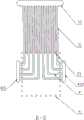
图2为实施例1的U形水冷返料器的隔板、集箱及集箱连接管示意图;Fig. 2 is the clapboard, header and header connecting pipe schematic diagram of the U-shaped water-cooled feeder of
图3为实施例1的U形水冷返料器的工质流程示意图;Fig. 3 is the working medium flow schematic diagram of the U-shaped water-cooled feeder of
图4为本发明的一种U形水冷返料器实施例2的U形水冷返料器的工质流程示意图;Fig. 4 is a schematic flow chart of the working medium of the U-shaped water-cooled
图5为实施例2的U形水冷返料器的A-A剖面示意图;Fig. 5 is the A-A sectional schematic diagram of the U-shaped water-cooled feeder of
图6为实施例2的U形水冷返料器的B-B剖面示意图。Fig. 6 is a B-B cross-sectional schematic view of the U-shaped water-cooled feeder of
具体实施方式Detailed ways
实施例1Example 1
如图1、图2和图3所示的水冷U形返料器,由横截面为矩形的下降管1、上升管2和返料管3依次相连而成;下降管1与上升管2之间设有中间隔板4,二者下部相通;上升管2与返料管3之间设有返料隔板5,二者上部相通;下降管1和上升管2底部设有布风板6;The water-cooled U-shaped feeder shown in Fig. 1, Fig. 2 and Fig. 3 is formed by successively connecting the descending
返料器外壳由四片膜式水冷壁组成,分别是:构成下降管前壁11、上升管顶板21、返料管前壁31的前片,构成下降管后壁12、布风板6、返料管后壁32的后片,分别构成下降管1左右壁、上升管2左右壁、返料管3左右壁的返料器外壳左壁和右壁;上述膜式水冷壁内侧均敷设耐火防磨材料。The shell of the feeder is composed of four membrane-type water-cooled walls, which are: the
返料管3与炉膛相通的返料口处设有环形的返料口集箱30,下降管1顶部设有环形的返料器出口集箱10;返料口集箱30为返料器冷却工质的入口集箱,其与汽包下降管相连;返料器出口集箱10为返料器冷却工质的出口集箱,其与汽包上部相连,或经水冷分离器水冷管与汽包相连。An
图2为隔板、集箱及集箱连接管的示意图,为便于看清水冷管布置方式,图中未画出管间鳍片和耐火材料,实际隔板的水冷管间带有鳍片,以便于敷设耐火材料。返料管前壁31中部设有水平的返料管前壁集箱33,下降管后壁12中部设有水平的下降管后壁集箱13;返料管前壁31从返料口集箱30引出的每两根相邻水冷管中的一根进行跳管,与返料管前壁集箱33相连;下降管后壁12汇入返料器出口集箱10的每两根相邻水冷管中的一根进行跳管,与下降管后壁集箱13相连;也就是说,返料管前壁31有一半的水冷管最终通入返料器出口集箱10,而另一半水冷管从返料口集箱30引出后,仅延伸至返料管前壁31中部就结束于返料管前壁集箱33;同样,下降管后壁12上部的水冷管中,只有一半是由返料口集箱30引来的,而另一半水冷管是从下降管后壁集箱13引出、并结束于返料器出口集箱10的。Figure 2 is a schematic diagram of the clapboard, header and header connecting pipes. In order to facilitate the arrangement of the water-cooled tubes, the fins and refractory materials between the tubes are not shown in the figure. The actual clapboard has fins between the water-cooled tubes. In order to facilitate the laying of refractory materials. The middle part of the return
返料管后壁32每两根相邻水冷管中的一根,在返料管后壁32与布风板6交界处进行跳管,并弯管至竖直向上延伸入返料器内,汇入水平的返料隔板集箱50,形成返料隔板5;返料隔板5两面和顶部均敷设耐火防磨材料;返料隔板集箱50低于下降管后壁集箱13,二者通过集箱连接管相连。One of the two adjacent water-cooling pipes on the rear wall of the
下降管前壁11每两根相邻水冷管中的一根,在下降管前壁11与上升管顶板21交界处进行跳管,竖直向下延伸入返料器内,汇入水平的中间隔板集箱40,形成中间隔板4;中间隔板4两面和底部均敷设耐火防磨材料;中间隔板集箱40与返料管前壁集箱33等高,二者通过集箱连接管相连。One of every two adjacent water-cooled pipes on the front wall of the
运行时,从汽包下降管引来的汽包水中的大部分由返料口集箱30进入返料器,分别沿返料器外壳的前、后、左、右四片,向上流动,汇入返料器出口集箱10;一小部分沿返料管前壁31、经返料管前壁集箱33、第一集箱连接管7、中间隔板集箱40,流经中间隔板4和下降管前壁11,汇入返料器出口集箱10;还有一小部分沿返料管后壁32、返料隔板5、经返料隔板集箱50、第二集箱连接管8、下降管后壁12,也汇入返料器出口集箱10。During operation, most of the steam drum water drawn from the steam drum downcomer enters the feeder from the
实施例2Example 2
如图4所示的水冷U形返料器,由横截面为矩形的下降管1、上升管2和返料管3依次相连而成;下降管1与上升管2之间设有中间隔板4,二者下部相通;上升管2与返料管3之间设有返料隔板5,二者上部相通;下降管1和上升管2底部设有布风板6。As shown in Figure 4, the water-cooled U-shaped feeder is formed by successively connecting the descending
返料器外壳由四片膜式水冷壁组成,分别是:构成下降管前壁11、上升管顶板21、返料管前壁31的前片,构成下降管后壁12、布风板6、返料管后壁32的后片,分别构成下降管1左右壁、上升管2左右壁、返料管3左右壁的返料器外壳左壁和右壁;上述膜式水冷壁内侧均敷设耐火防磨材料。The shell of the feeder is composed of four membrane-type water-cooled walls, which are: the
返料管3与炉膛相通的返料口处设有环形的返料口集箱30,下降管1顶部设有环形的返料器出口集箱10;返料口集箱30为返料器冷却工质的入口集箱,其与汽包下降管相连;返料器出口集箱10为返料器冷却工质的出口集箱,其与汽包上部相连,或经水冷分离器水冷管与汽包相连。An
返料管前壁31中部设有水平的返料管前壁集箱33,下降管后壁12中部设有水平的下降管后壁集箱13;返料管前壁31从返料口集箱30引出的每两根相邻水冷管中的一根进行跳管,与返料管前壁集箱33相连;下降管后壁12汇入返料器出口集箱10的每两根相邻水冷管中的一根进行跳管,与下降管后壁集箱13相连;也就是说,返料管前壁31有一半的水冷管最终通入返料器出口集箱10,而另一半水冷管从返料口集箱30引出后,仅延伸至返料管前壁31中部就结束于返料管前壁集箱33;同样,下降管后壁12上部的水冷管中,只有一半是由返料口集箱30引来的,而另一半水冷管是从下降管后壁集箱13引出、并结束于返料器出口集箱10的。The middle part of the return
图5示出了返料隔板的水冷管形状,为便于看清,图中未画出耐火材料和管间鳍片,实际隔板的水冷管间带有鳍片,以便于敷设耐火材料。返料管后壁32每两根相邻水冷管中的一根,在返料管后壁32与布风板6交界处进行跳管,并弯管至竖直向上延伸入返料器内,在竖直管段所在平面内,左侧一半水冷管向左、右侧一半水冷管向右,弯管至水平方向穿出返料器外壳,分别汇入竖直设置在返料器外壳左壁外侧的返料隔板左集箱501和右壁外侧的返料隔板右集箱502,返料隔板集箱501、502最高点与下降管后壁集箱13的最高点等高,返料隔板集箱501、502与下降管后壁集箱13通过第二集箱连接管8相连。左、右侧弯管形成的平板构成了返料隔板5,返料隔板5两面和顶部均敷设耐火防磨材料。Figure 5 shows the shape of the water-cooled tube of the return partition. For the sake of clarity, the refractory material and the fins between the tubes are not shown in the figure. The actual partition has fins between the water-cooled tubes to facilitate the laying of refractory materials. One of the two adjacent water-cooling pipes on the rear wall of the
图6示出了中间隔板的水冷管形状,为了便于看清,图中未画出耐火材料和管间鳍片。下降管前壁11每两根相邻水冷管中的一根,在下降管前壁11与上升管顶板21交界处进行跳管,竖直向下延伸入返料器内,在竖直管段所在平面内,左侧一半水冷管向左、右侧一半水冷管向右,弯管至水平方向穿出返料器外壳,分别汇入竖直设置在返料器外壳左壁外侧的中间隔板集箱401和右壁外侧的中间隔板集箱402,中间隔板集箱401、402最低点高于返料管前壁集箱33,二者通过第一集箱连接管7相连;左、右侧弯管形成的平板构成了中间隔板4,中间隔板4两面和底部均敷设耐火防磨材料。Figure 6 shows the shape of the water-cooled tubes of the middle partition, for the sake of clarity, the refractory material and inter-tube fins are not shown in the figure. One of every two adjacent water-cooled pipes on the front wall of the
运行时,从汽包下降管引来的汽包水中的大部分由返料口集箱30进入返料器,分别沿返料器外壳的前、后、左、右四片,向上流动,汇入返料器出口集箱10;一小部分沿返料管前壁31、经返料管前壁集箱33、第一集箱连接管7、中间隔板集箱401、402,流经中间隔板4和下降管前壁11,汇入返料器出口集箱10;还有一小部分沿返料管后壁32、返料隔板5、经返料隔板集箱501、502、第二集箱连接管8、下降管后壁12,也汇入返料器出口集箱10。During operation, most of the steam drum water drawn from the steam drum downcomer enters the feeder from the
本发明的原理是:Principle of the present invention is:
采用来自汽包下降管的汽包水作为返料器冷却工质时,返料器中的工质与炉膛水冷壁中的工质温度一致,膨胀系数也相同,配合汽包水冷却的水冷分离器使用时,可以消除炉膛与分离返料侧的胀差,取消膨胀节,从而简化设备。但由于汽包水只能以自然循环的方式流动,即流动方向必须是自下而上,这使得结构复杂的返料器的工质流程设计困难。When the drum water from the downcomer of the steam drum is used as the cooling medium of the feeder, the temperature of the working medium in the feeder is the same as that in the water wall of the furnace, and the expansion coefficient is also the same. When the device is used, the expansion difference between the furnace and the separation and return side can be eliminated, and the expansion joint can be eliminated, thereby simplifying the equipment. However, since the drum water can only flow in a natural circulation mode, that is, the flow direction must be from bottom to top, which makes it difficult to design the working fluid process of the complex structure of the feeder.
本发明巧妙的利用跳管方式,一方面使返料器外壳水冷壁延伸至返料器内部形成了水冷隔板,同时又从返料器下降管后壁和返料管前壁分出半数的水冷管形成两个集箱,与两个隔板的工质集箱相连,打通了工质流程。The present invention cleverly utilizes the pipe jumping method. On the one hand, the water-cooled wall of the shell of the feeder is extended to the inside of the feeder to form a water-cooled partition. The water-cooled tubes form two headers, which are connected to the working fluid headers of the two partitions to open up the working fluid flow.
Claims (3)
Priority Applications (5)
| Application Number | Priority Date | Filing Date | Title |
|---|---|---|---|
| CN200910087879ACN101929672B (en) | 2009-06-24 | 2009-06-24 | U-shaped water-cooling material returner |
| PCT/CN2010/074380WO2010149057A1 (en) | 2009-06-24 | 2010-06-24 | U-shaped water-cooled stuff back-feeder |
| PL10791563TPL2447604T3 (en) | 2009-06-24 | 2010-06-24 | U-shaped water-cooled back-feeder valve for fluidized bed reactor |
| EP10791563.9AEP2447604B1 (en) | 2009-06-24 | 2010-06-24 | U-shaped water-cooled back-feeder valve for fluidized bed reactor |
| US13/380,433US9476585B2 (en) | 2009-06-24 | 2010-06-24 | Water-cooling U-valve |
Applications Claiming Priority (1)
| Application Number | Priority Date | Filing Date | Title |
|---|---|---|---|
| CN200910087879ACN101929672B (en) | 2009-06-24 | 2009-06-24 | U-shaped water-cooling material returner |
Publications (2)
| Publication Number | Publication Date |
|---|---|
| CN101929672A CN101929672A (en) | 2010-12-29 |
| CN101929672Btrue CN101929672B (en) | 2012-10-24 |
Family
ID=43368998
Family Applications (1)
| Application Number | Title | Priority Date | Filing Date |
|---|---|---|---|
| CN200910087879AActiveCN101929672B (en) | 2009-06-24 | 2009-06-24 | U-shaped water-cooling material returner |
Country Status (5)
| Country | Link |
|---|---|
| US (1) | US9476585B2 (en) |
| EP (1) | EP2447604B1 (en) |
| CN (1) | CN101929672B (en) |
| PL (1) | PL2447604T3 (en) |
| WO (1) | WO2010149057A1 (en) |
Families Citing this family (7)
| Publication number | Priority date | Publication date | Assignee | Title |
|---|---|---|---|---|
| CN101596433B (en)* | 2009-07-15 | 2011-07-06 | 中国科学院工程热物理研究所 | Cooling baffles for U-shaped refeeders |
| EP2884172A1 (en)* | 2013-12-16 | 2015-06-17 | Doosan Lentjes GmbH | Fluidized bed syphon |
| CN107795985B (en)* | 2017-11-06 | 2019-04-19 | 南京泰润电力工程有限公司 | A kind of fluidized-bed combustion boiler returning charge, the technique for putting ash |
| CN108105762B (en)* | 2017-12-27 | 2019-04-16 | 杨松 | It is a kind of to prepare kaolin Circulation fluidized-bed furnace material returning device application method |
| CN108105763B (en)* | 2017-12-27 | 2019-04-16 | 杨松 | It is a kind of to prepare kaolin Circulation fluidized-bed furnace material returning device |
| CN109911633A (en)* | 2019-04-25 | 2019-06-21 | 攀钢集团钛业有限责任公司 | U valve |
| CN114135893B (en)* | 2021-10-25 | 2024-04-12 | 国家能源集团国源电力有限公司 | Material returning device and boiler |
Citations (4)
| Publication number | Priority date | Publication date | Assignee | Title |
|---|---|---|---|---|
| US4813479A (en)* | 1986-12-11 | 1989-03-21 | Gotaverken Energy Ab | Adjustable particle cooler for a circulating fluidized bed reactor |
| US5218932A (en)* | 1992-03-02 | 1993-06-15 | Foster Wheeler Energy Corporation | Fluidized bed reactor utilizing a baffle system and method of operating same |
| CN2192807Y (en)* | 1994-04-20 | 1995-03-22 | 开封锅炉厂 | Energy-saving outer circulation fluidizing bed boiler |
| CN201427045Y (en)* | 2009-06-24 | 2010-03-24 | 中国科学院工程热物理研究所 | A U-shaped water-cooled feeder |
Family Cites Families (45)
| Publication number | Priority date | Publication date | Assignee | Title |
|---|---|---|---|---|
| US1980785A (en)* | 1932-12-29 | 1934-11-13 | Gen Electric | Elastic fluid generator |
| US2332534A (en)* | 1938-09-07 | 1943-10-26 | Babcock & Wilcox Co | Steam generator |
| US2939435A (en)* | 1957-02-06 | 1960-06-07 | Babcock & Wilcox Co | Marine boiler |
| US3146759A (en)* | 1962-03-19 | 1964-09-01 | Riley Stoker Corp | Steam generating unit |
| US3146760A (en)* | 1962-07-16 | 1964-09-01 | Riley Stoker Corp | Steam generating unit |
| US3284070A (en)* | 1963-02-01 | 1966-11-08 | Yawata Iron & Steel Co | Hot blast stove having one common combustion chamber |
| US3324837A (en)* | 1964-05-27 | 1967-06-13 | Foster Wheeler Corp | Multiple pass design for once-through steam generators |
| GB1114441A (en)* | 1964-05-27 | 1968-05-22 | Foster Wheeler Corp | Multiple pass arrangements for once-through steam generators |
| US3310041A (en)* | 1965-08-04 | 1967-03-21 | Babcock & Wilcox Co | Vapor generator heating gas pass tube support and partition wall construction |
| US3893426A (en)* | 1974-03-25 | 1975-07-08 | Foster Wheeler Corp | Heat exchanger utilizing adjoining fluidized beds |
| US4251228A (en)* | 1979-05-30 | 1981-02-17 | Texaco Development Corporation | Production of cleaned and cooled synthesis gas |
| US4289502A (en)* | 1979-05-30 | 1981-09-15 | Texaco Development Corporation | Apparatus for the production of cleaned and cooled synthesis gas |
| US4377394A (en)* | 1979-05-30 | 1983-03-22 | Texaco Development Corporation | Apparatus for the production of cleaned and cooled synthesis gas |
| US4328006A (en)* | 1979-05-30 | 1982-05-04 | Texaco Development Corporation | Apparatus for the production of cleaned and cooled synthesis gas |
| US4326856A (en)* | 1979-05-30 | 1982-04-27 | Texaco Development Corporation | Production of cleaned and cooled synthesis gas |
| US4328008A (en)* | 1979-05-30 | 1982-05-04 | Texaco Development Corporation | Method for the production of cleaned and cooled synthesis gas |
| US4248604A (en)* | 1979-07-13 | 1981-02-03 | Texaco Inc. | Gasification process |
| US4247302A (en)* | 1979-07-13 | 1981-01-27 | Texaco Inc. | Process for gasification and production of by-product superheated steam |
| JPS5674501A (en)* | 1979-11-21 | 1981-06-20 | Mitsubishi Heavy Ind Ltd | Super critical pressure variable operation type forcedly once through boiler |
| US4479458A (en)* | 1983-10-03 | 1984-10-30 | Foster Wheeler Energy Corporation | Hexagonal pressurized fluidized bed reactor |
| DE3525676A1 (en)* | 1985-07-18 | 1987-01-22 | Kraftwerk Union Ag | STEAM GENERATOR |
| CA1285375C (en)* | 1986-01-21 | 1991-07-02 | Takahiro Ohshita | Thermal reactor |
| US4665864A (en)* | 1986-07-14 | 1987-05-19 | Foster Wheeler Energy Corporation | Steam generator and method of operating a steam generator utilizing separate fluid and combined gas flow circuits |
| DE3803437A1 (en) | 1987-06-02 | 1988-12-15 | Lentjes Ag | FLUIDIZED LAYER REACTOR |
| JPH01184301A (en)* | 1988-01-19 | 1989-07-24 | Mitsubishi Heavy Ind Ltd | Circulating fluidized bed type boiler |
| DK120288D0 (en)* | 1988-03-04 | 1988-03-04 | Aalborg Boilers | FLUID BED COMBUSTION REACTOR AND METHOD FOR OPERATING A FLUID BED COMBUSTION REACTOR |
| US4947804A (en)* | 1989-07-28 | 1990-08-14 | Foster Wheeler Energy Corporation | Fluidized bed steam generation system and method having an external heat exchanger |
| US5037617A (en)* | 1990-01-04 | 1991-08-06 | Stone & Webster Engineering Corporation | Apparatus for the return of particulate solids through a cyclone separator to a vessel |
| US5281398A (en)* | 1990-10-15 | 1994-01-25 | A. Ahlstrom Corporation | Centrifugal separator |
| US5094191A (en)* | 1991-01-31 | 1992-03-10 | Foster Wheeler Energy Corporation | Steam generating system utilizing separate fluid flow circuitry between the furnace section and the separating section |
| DK0692999T4 (en)* | 1993-04-05 | 2005-10-03 | Foster Wheeler Energia Oy | Fluidized bed reactor system and method for making same |
| US5378253A (en)* | 1993-09-28 | 1995-01-03 | The Babcock & Wilcox Company | Water/steam-cooled U-beam impact type article separator |
| JPH1184301A (en) | 1997-09-05 | 1999-03-26 | Canon Inc | Scanning optical device |
| FI107758B (en)* | 1999-11-10 | 2001-09-28 | Foster Wheeler Energia Oy | Reactor with circulating fluidized bed |
| US6692552B2 (en)* | 2001-03-20 | 2004-02-17 | Stone & Webster Process Technology, Inc. | Riser termination device |
| US6925969B1 (en)* | 2004-06-24 | 2005-08-09 | Diamond Power International, Inc. | Boiler wall box cooling system |
| FR2891893B1 (en)* | 2005-10-07 | 2007-12-21 | Alstom Technology Ltd | CIRCULATING FLUIDIZED BED REACTOR WITH CONVERTIBLE COMBUSTION PROCESS |
| US7587995B2 (en)* | 2005-11-03 | 2009-09-15 | Babcock & Wilcox Power Generation Group, Inc. | Radiant syngas cooler |
| US8684070B2 (en)* | 2006-08-15 | 2014-04-01 | Babcock & Wilcox Power Generation Group, Inc. | Compact radial platen arrangement for radiant syngas cooler |
| US20090031967A1 (en)* | 2007-07-31 | 2009-02-05 | Alstom Technology Ltd | Integral waterwall external heat exchangers |
| CN201273564Y (en)* | 2008-09-08 | 2009-07-15 | 济南锅炉集团有限公司 | Water-cooling tongue plate |
| CN101596433B (en) | 2009-07-15 | 2011-07-06 | 中国科学院工程热物理研究所 | Cooling baffles for U-shaped refeeders |
| US20140352634A1 (en)* | 2011-11-21 | 2014-12-04 | Eugene Sullivan | Method and Apparatus for Improved Firing of Biomass and Other Solid Fuels for Steam Production and Gasification |
| CA2878173C (en)* | 2012-07-27 | 2018-09-25 | Exxonmobil Upstream Research Company | Multiphase separation system |
| WO2015124007A1 (en)* | 2014-02-19 | 2015-08-27 | 王森 | Fluidized bed boiler with integration of multifunctional inertial gravity separators and multiple types of furnaces |
- 2009
- 2009-06-24CNCN200910087879Apatent/CN101929672B/enactiveActive
- 2010
- 2010-06-24USUS13/380,433patent/US9476585B2/enactiveActive
- 2010-06-24EPEP10791563.9Apatent/EP2447604B1/enactiveActive
- 2010-06-24PLPL10791563Tpatent/PL2447604T3/enunknown
- 2010-06-24WOPCT/CN2010/074380patent/WO2010149057A1/enactiveApplication Filing
Patent Citations (4)
| Publication number | Priority date | Publication date | Assignee | Title |
|---|---|---|---|---|
| US4813479A (en)* | 1986-12-11 | 1989-03-21 | Gotaverken Energy Ab | Adjustable particle cooler for a circulating fluidized bed reactor |
| US5218932A (en)* | 1992-03-02 | 1993-06-15 | Foster Wheeler Energy Corporation | Fluidized bed reactor utilizing a baffle system and method of operating same |
| CN2192807Y (en)* | 1994-04-20 | 1995-03-22 | 开封锅炉厂 | Energy-saving outer circulation fluidizing bed boiler |
| CN201427045Y (en)* | 2009-06-24 | 2010-03-24 | 中国科学院工程热物理研究所 | A U-shaped water-cooled feeder |
Also Published As
| Publication number | Publication date |
|---|---|
| PL2447604T3 (en) | 2015-01-30 |
| WO2010149057A1 (en) | 2010-12-29 |
| EP2447604B1 (en) | 2014-08-20 |
| US9476585B2 (en) | 2016-10-25 |
| US20120103584A1 (en) | 2012-05-03 |
| EP2447604A1 (en) | 2012-05-02 |
| EP2447604A4 (en) | 2012-12-19 |
| CN101929672A (en) | 2010-12-29 |
Similar Documents
| Publication | Publication Date | Title |
|---|---|---|
| CN101929672B (en) | U-shaped water-cooling material returner | |
| WO2011006422A1 (en) | Cooling baffles of u-shaped returning device | |
| CN102116471B (en) | Device and method for recovering bottom slag heat of circulating fluidized bed boiler | |
| CN201427045Y (en) | A U-shaped water-cooled feeder | |
| CN102062386B (en) | Rapid-installation water pipe boiler with medium and high pressure single-boiler barrel structure | |
| CN101556076B (en) | Single drum horizontal vertical threaded smoke tube large water fire tube hot water boiler | |
| EP0497528A1 (en) | Steam generating system utilizing separate fluid flow circuitry between the furnace section and the separating section | |
| CN104654289B (en) | A kind of crop straw burning fluidized-bed combustion boiler | |
| CN104676617B (en) | A kind of burning boiler flue accumulation prevention structure | |
| UA79174C2 (en) | Boiler unit comprising stationary supporting structure | |
| CN101551158B (en) | Large-scale water-fire tube hot water boiler of double-barrel transverse vertical type threaded flue | |
| CN201954517U (en) | Medium and high pressure quick assembled water tube boiler with single boiler barrel structure | |
| CN109504461A (en) | Recycle the gasification system of high-temperature synthesis gas heat | |
| CN212298928U (en) | Horizontal combined fuel oil and gas biomass steam generator | |
| CN101696798B (en) | Compact circulating fluidized bed boiler with special division wall | |
| CN207439171U (en) | corner tube boiler | |
| SE437124B (en) | A boiler with a furnace chamber clad with cooling tubes. | |
| CN104566387A (en) | Boiler for domestic garbage incineration | |
| CN204478075U (en) | Consumer waste incineration boiler | |
| CN220793096U (en) | Vertical square hearth boiler | |
| CN220669427U (en) | Vertical square furnace steam generating device | |
| JP7602634B2 (en) | Circulating Fluidized Bed Boiler | |
| CN214172193U (en) | Biomass-fired evaporator | |
| JP5844021B1 (en) | Fluidized bed heat exchanger | |
| CN203687064U (en) | Biomass boiler water-cooling slag hole structure |
Legal Events
| Date | Code | Title | Description |
|---|---|---|---|
| C06 | Publication | ||
| PB01 | Publication | ||
| C10 | Entry into substantive examination | ||
| SE01 | Entry into force of request for substantive examination | ||
| C14 | Grant of patent or utility model | ||
| GR01 | Patent grant | ||
| EE01 | Entry into force of recordation of patent licensing contract | Application publication date:20101229 Assignee:Jiangsu Sifang Boiler Co., Ltd. Assignor:Institute of Engineering Thermophysics, Chinese Academy of Sciences Contract record no.:2017990000075 Denomination of invention:U-shaped water-cooling material returner Granted publication date:20121024 License type:Exclusive License Record date:20170309 | |
| EE01 | Entry into force of recordation of patent licensing contract |