CN101919753A - Method and device for sutureless implantation of artificial aortic valve or mitral valve - Google Patents
Method and device for sutureless implantation of artificial aortic valve or mitral valveDownload PDFInfo
- Publication number
- CN101919753A CN101919753ACN2010101557067ACN201010155706ACN101919753ACN 101919753 ACN101919753 ACN 101919753ACN 2010101557067 ACN2010101557067 ACN 2010101557067ACN 201010155706 ACN201010155706 ACN 201010155706ACN 101919753 ACN101919753 ACN 101919753A
- Authority
- CN
- China
- Prior art keywords
- valve
- housing
- shell
- prosthetic
- support frame
- Prior art date
- Legal status (The legal status is an assumption and is not a legal conclusion. Google has not performed a legal analysis and makes no representation as to the accuracy of the status listed.)
- Pending
Links
Images


Classifications
- A—HUMAN NECESSITIES
- A61—MEDICAL OR VETERINARY SCIENCE; HYGIENE
- A61F—FILTERS IMPLANTABLE INTO BLOOD VESSELS; PROSTHESES; DEVICES PROVIDING PATENCY TO, OR PREVENTING COLLAPSING OF, TUBULAR STRUCTURES OF THE BODY, e.g. STENTS; ORTHOPAEDIC, NURSING OR CONTRACEPTIVE DEVICES; FOMENTATION; TREATMENT OR PROTECTION OF EYES OR EARS; BANDAGES, DRESSINGS OR ABSORBENT PADS; FIRST-AID KITS
- A61F2/00—Filters implantable into blood vessels; Prostheses, i.e. artificial substitutes or replacements for parts of the body; Appliances for connecting them with the body; Devices providing patency to, or preventing collapsing of, tubular structures of the body, e.g. stents
- A61F2/95—Instruments specially adapted for placement or removal of stents or stent-grafts
- A61F2/962—Instruments specially adapted for placement or removal of stents or stent-grafts having an outer sleeve
- A61F2/966—Instruments specially adapted for placement or removal of stents or stent-grafts having an outer sleeve with relative longitudinal movement between outer sleeve and prosthesis, e.g. using a push rod
- A—HUMAN NECESSITIES
- A61—MEDICAL OR VETERINARY SCIENCE; HYGIENE
- A61F—FILTERS IMPLANTABLE INTO BLOOD VESSELS; PROSTHESES; DEVICES PROVIDING PATENCY TO, OR PREVENTING COLLAPSING OF, TUBULAR STRUCTURES OF THE BODY, e.g. STENTS; ORTHOPAEDIC, NURSING OR CONTRACEPTIVE DEVICES; FOMENTATION; TREATMENT OR PROTECTION OF EYES OR EARS; BANDAGES, DRESSINGS OR ABSORBENT PADS; FIRST-AID KITS
- A61F2/00—Filters implantable into blood vessels; Prostheses, i.e. artificial substitutes or replacements for parts of the body; Appliances for connecting them with the body; Devices providing patency to, or preventing collapsing of, tubular structures of the body, e.g. stents
- A61F2/02—Prostheses implantable into the body
- A61F2/24—Heart valves ; Vascular valves, e.g. venous valves; Heart implants, e.g. passive devices for improving the function of the native valve or the heart muscle; Transmyocardial revascularisation [TMR] devices; Valves implantable in the body
- A61F2/2427—Devices for manipulating or deploying heart valves during implantation
- A—HUMAN NECESSITIES
- A61—MEDICAL OR VETERINARY SCIENCE; HYGIENE
- A61F—FILTERS IMPLANTABLE INTO BLOOD VESSELS; PROSTHESES; DEVICES PROVIDING PATENCY TO, OR PREVENTING COLLAPSING OF, TUBULAR STRUCTURES OF THE BODY, e.g. STENTS; ORTHOPAEDIC, NURSING OR CONTRACEPTIVE DEVICES; FOMENTATION; TREATMENT OR PROTECTION OF EYES OR EARS; BANDAGES, DRESSINGS OR ABSORBENT PADS; FIRST-AID KITS
- A61F2/00—Filters implantable into blood vessels; Prostheses, i.e. artificial substitutes or replacements for parts of the body; Appliances for connecting them with the body; Devices providing patency to, or preventing collapsing of, tubular structures of the body, e.g. stents
- A61F2/02—Prostheses implantable into the body
- A61F2/24—Heart valves ; Vascular valves, e.g. venous valves; Heart implants, e.g. passive devices for improving the function of the native valve or the heart muscle; Transmyocardial revascularisation [TMR] devices; Valves implantable in the body
- A61F2/2412—Heart valves ; Vascular valves, e.g. venous valves; Heart implants, e.g. passive devices for improving the function of the native valve or the heart muscle; Transmyocardial revascularisation [TMR] devices; Valves implantable in the body with soft flexible valve members, e.g. tissue valves shaped like natural valves
- A61F2/2418—Scaffolds therefor, e.g. support stents
- A—HUMAN NECESSITIES
- A61—MEDICAL OR VETERINARY SCIENCE; HYGIENE
- A61F—FILTERS IMPLANTABLE INTO BLOOD VESSELS; PROSTHESES; DEVICES PROVIDING PATENCY TO, OR PREVENTING COLLAPSING OF, TUBULAR STRUCTURES OF THE BODY, e.g. STENTS; ORTHOPAEDIC, NURSING OR CONTRACEPTIVE DEVICES; FOMENTATION; TREATMENT OR PROTECTION OF EYES OR EARS; BANDAGES, DRESSINGS OR ABSORBENT PADS; FIRST-AID KITS
- A61F2/00—Filters implantable into blood vessels; Prostheses, i.e. artificial substitutes or replacements for parts of the body; Appliances for connecting them with the body; Devices providing patency to, or preventing collapsing of, tubular structures of the body, e.g. stents
- A61F2/02—Prostheses implantable into the body
- A61F2/24—Heart valves ; Vascular valves, e.g. venous valves; Heart implants, e.g. passive devices for improving the function of the native valve or the heart muscle; Transmyocardial revascularisation [TMR] devices; Valves implantable in the body
- A61F2/2427—Devices for manipulating or deploying heart valves during implantation
- A61F2/2436—Deployment by retracting a sheath
- A—HUMAN NECESSITIES
- A61—MEDICAL OR VETERINARY SCIENCE; HYGIENE
- A61F—FILTERS IMPLANTABLE INTO BLOOD VESSELS; PROSTHESES; DEVICES PROVIDING PATENCY TO, OR PREVENTING COLLAPSING OF, TUBULAR STRUCTURES OF THE BODY, e.g. STENTS; ORTHOPAEDIC, NURSING OR CONTRACEPTIVE DEVICES; FOMENTATION; TREATMENT OR PROTECTION OF EYES OR EARS; BANDAGES, DRESSINGS OR ABSORBENT PADS; FIRST-AID KITS
- A61F2/00—Filters implantable into blood vessels; Prostheses, i.e. artificial substitutes or replacements for parts of the body; Appliances for connecting them with the body; Devices providing patency to, or preventing collapsing of, tubular structures of the body, e.g. stents
- A61F2/95—Instruments specially adapted for placement or removal of stents or stent-grafts
- A61F2/9517—Instruments specially adapted for placement or removal of stents or stent-grafts handle assemblies therefor
- A—HUMAN NECESSITIES
- A61—MEDICAL OR VETERINARY SCIENCE; HYGIENE
- A61F—FILTERS IMPLANTABLE INTO BLOOD VESSELS; PROSTHESES; DEVICES PROVIDING PATENCY TO, OR PREVENTING COLLAPSING OF, TUBULAR STRUCTURES OF THE BODY, e.g. STENTS; ORTHOPAEDIC, NURSING OR CONTRACEPTIVE DEVICES; FOMENTATION; TREATMENT OR PROTECTION OF EYES OR EARS; BANDAGES, DRESSINGS OR ABSORBENT PADS; FIRST-AID KITS
- A61F2/00—Filters implantable into blood vessels; Prostheses, i.e. artificial substitutes or replacements for parts of the body; Appliances for connecting them with the body; Devices providing patency to, or preventing collapsing of, tubular structures of the body, e.g. stents
- A61F2/95—Instruments specially adapted for placement or removal of stents or stent-grafts
- A61F2/962—Instruments specially adapted for placement or removal of stents or stent-grafts having an outer sleeve
- A61F2/966—Instruments specially adapted for placement or removal of stents or stent-grafts having an outer sleeve with relative longitudinal movement between outer sleeve and prosthesis, e.g. using a push rod
- A61F2/9661—Instruments specially adapted for placement or removal of stents or stent-grafts having an outer sleeve with relative longitudinal movement between outer sleeve and prosthesis, e.g. using a push rod the proximal portion of the stent or stent-graft is released first
- A—HUMAN NECESSITIES
- A61—MEDICAL OR VETERINARY SCIENCE; HYGIENE
- A61F—FILTERS IMPLANTABLE INTO BLOOD VESSELS; PROSTHESES; DEVICES PROVIDING PATENCY TO, OR PREVENTING COLLAPSING OF, TUBULAR STRUCTURES OF THE BODY, e.g. STENTS; ORTHOPAEDIC, NURSING OR CONTRACEPTIVE DEVICES; FOMENTATION; TREATMENT OR PROTECTION OF EYES OR EARS; BANDAGES, DRESSINGS OR ABSORBENT PADS; FIRST-AID KITS
- A61F2220/00—Fixations or connections for prostheses classified in groups A61F2/00 - A61F2/26 or A61F2/82 or A61F9/00 or A61F11/00 or subgroups thereof
- A61F2220/0008—Fixation appliances for connecting prostheses to the body
- A61F2220/0016—Fixation appliances for connecting prostheses to the body with sharp anchoring protrusions, e.g. barbs, pins, spikes
- A—HUMAN NECESSITIES
- A61—MEDICAL OR VETERINARY SCIENCE; HYGIENE
- A61F—FILTERS IMPLANTABLE INTO BLOOD VESSELS; PROSTHESES; DEVICES PROVIDING PATENCY TO, OR PREVENTING COLLAPSING OF, TUBULAR STRUCTURES OF THE BODY, e.g. STENTS; ORTHOPAEDIC, NURSING OR CONTRACEPTIVE DEVICES; FOMENTATION; TREATMENT OR PROTECTION OF EYES OR EARS; BANDAGES, DRESSINGS OR ABSORBENT PADS; FIRST-AID KITS
- A61F2220/00—Fixations or connections for prostheses classified in groups A61F2/00 - A61F2/26 or A61F2/82 or A61F9/00 or A61F11/00 or subgroups thereof
- A61F2220/0025—Connections or couplings between prosthetic parts, e.g. between modular parts; Connecting elements
- A61F2220/005—Connections or couplings between prosthetic parts, e.g. between modular parts; Connecting elements using adhesives
- A—HUMAN NECESSITIES
- A61—MEDICAL OR VETERINARY SCIENCE; HYGIENE
- A61F—FILTERS IMPLANTABLE INTO BLOOD VESSELS; PROSTHESES; DEVICES PROVIDING PATENCY TO, OR PREVENTING COLLAPSING OF, TUBULAR STRUCTURES OF THE BODY, e.g. STENTS; ORTHOPAEDIC, NURSING OR CONTRACEPTIVE DEVICES; FOMENTATION; TREATMENT OR PROTECTION OF EYES OR EARS; BANDAGES, DRESSINGS OR ABSORBENT PADS; FIRST-AID KITS
- A61F2220/00—Fixations or connections for prostheses classified in groups A61F2/00 - A61F2/26 or A61F2/82 or A61F9/00 or A61F11/00 or subgroups thereof
- A61F2220/0025—Connections or couplings between prosthetic parts, e.g. between modular parts; Connecting elements
- A61F2220/0058—Connections or couplings between prosthetic parts, e.g. between modular parts; Connecting elements soldered or brazed or welded
- A—HUMAN NECESSITIES
- A61—MEDICAL OR VETERINARY SCIENCE; HYGIENE
- A61F—FILTERS IMPLANTABLE INTO BLOOD VESSELS; PROSTHESES; DEVICES PROVIDING PATENCY TO, OR PREVENTING COLLAPSING OF, TUBULAR STRUCTURES OF THE BODY, e.g. STENTS; ORTHOPAEDIC, NURSING OR CONTRACEPTIVE DEVICES; FOMENTATION; TREATMENT OR PROTECTION OF EYES OR EARS; BANDAGES, DRESSINGS OR ABSORBENT PADS; FIRST-AID KITS
- A61F2220/00—Fixations or connections for prostheses classified in groups A61F2/00 - A61F2/26 or A61F2/82 or A61F9/00 or A61F11/00 or subgroups thereof
- A61F2220/0025—Connections or couplings between prosthetic parts, e.g. between modular parts; Connecting elements
- A61F2220/0066—Connections or couplings between prosthetic parts, e.g. between modular parts; Connecting elements stapled
- A—HUMAN NECESSITIES
- A61—MEDICAL OR VETERINARY SCIENCE; HYGIENE
- A61F—FILTERS IMPLANTABLE INTO BLOOD VESSELS; PROSTHESES; DEVICES PROVIDING PATENCY TO, OR PREVENTING COLLAPSING OF, TUBULAR STRUCTURES OF THE BODY, e.g. STENTS; ORTHOPAEDIC, NURSING OR CONTRACEPTIVE DEVICES; FOMENTATION; TREATMENT OR PROTECTION OF EYES OR EARS; BANDAGES, DRESSINGS OR ABSORBENT PADS; FIRST-AID KITS
- A61F2230/00—Geometry of prostheses classified in groups A61F2/00 - A61F2/26 or A61F2/82 or A61F9/00 or A61F11/00 or subgroups thereof
- A61F2230/0002—Two-dimensional shapes, e.g. cross-sections
- A61F2230/0028—Shapes in the form of latin or greek characters
- A61F2230/0054—V-shaped
- A—HUMAN NECESSITIES
- A61—MEDICAL OR VETERINARY SCIENCE; HYGIENE
- A61F—FILTERS IMPLANTABLE INTO BLOOD VESSELS; PROSTHESES; DEVICES PROVIDING PATENCY TO, OR PREVENTING COLLAPSING OF, TUBULAR STRUCTURES OF THE BODY, e.g. STENTS; ORTHOPAEDIC, NURSING OR CONTRACEPTIVE DEVICES; FOMENTATION; TREATMENT OR PROTECTION OF EYES OR EARS; BANDAGES, DRESSINGS OR ABSORBENT PADS; FIRST-AID KITS
- A61F2230/00—Geometry of prostheses classified in groups A61F2/00 - A61F2/26 or A61F2/82 or A61F9/00 or A61F11/00 or subgroups thereof
- A61F2230/0063—Three-dimensional shapes
- A61F2230/0067—Three-dimensional shapes conical
- A—HUMAN NECESSITIES
- A61—MEDICAL OR VETERINARY SCIENCE; HYGIENE
- A61F—FILTERS IMPLANTABLE INTO BLOOD VESSELS; PROSTHESES; DEVICES PROVIDING PATENCY TO, OR PREVENTING COLLAPSING OF, TUBULAR STRUCTURES OF THE BODY, e.g. STENTS; ORTHOPAEDIC, NURSING OR CONTRACEPTIVE DEVICES; FOMENTATION; TREATMENT OR PROTECTION OF EYES OR EARS; BANDAGES, DRESSINGS OR ABSORBENT PADS; FIRST-AID KITS
- A61F2250/00—Special features of prostheses classified in groups A61F2/00 - A61F2/26 or A61F2/82 or A61F9/00 or A61F11/00 or subgroups thereof
- A61F2250/0058—Additional features; Implant or prostheses properties not otherwise provided for
- A61F2250/006—Additional features; Implant or prostheses properties not otherwise provided for modular
Landscapes
- Health & Medical Sciences (AREA)
- Cardiology (AREA)
- Engineering & Computer Science (AREA)
- Biomedical Technology (AREA)
- Heart & Thoracic Surgery (AREA)
- Transplantation (AREA)
- Oral & Maxillofacial Surgery (AREA)
- Vascular Medicine (AREA)
- Life Sciences & Earth Sciences (AREA)
- Animal Behavior & Ethology (AREA)
- General Health & Medical Sciences (AREA)
- Public Health (AREA)
- Veterinary Medicine (AREA)
- Prostheses (AREA)
- Materials For Medical Uses (AREA)
Abstract
Translated fromChinese
Description
Translated fromChinese优先权要求priority claim
本申请要求于2009年3月20日提交的美国临时申请61/211430、于2009年3月30日提交的美国临时申请61/211431、于2009年3月30日提交的美国临时申请61/211432、于2009年3月30日提交的美国临时申请61/211433以及于2009年7月24日提交的美国临时申请61/228423的优先权,上述申请在此全文引用具有参考。This application claims U.S. Provisional Application 61/211430, filed March 20, 2009, U.S. Provisional Application 61/211431, filed March 30, 2009, U.S. Provisional Application 61/211432, filed March 30, 2009 , US Provisional Application 61/211433, filed March 30, 2009, and US Provisional Application 61/228423, filed July 24, 2009, which are hereby incorporated by reference in their entirety.
技术领域technical field
本发明涉及采用最小限度创伤手术的无缝合人工心脏瓣膜移植方法及医学装置。The invention relates to a non-seam artificial heart valve transplantation method and a medical device using minimal trauma operation.
背景技术Background technique
人工心脏瓣膜用于置换受损或患病的心脏瓣膜。在脊椎动物中,心脏为肌肉型器官,具有四个压缩室:左心房和右心房,以及左心室和右心室,上述每个均具备各自独立的单向瓣膜。天然心脏瓣膜定义为主动脉瓣膜、二尖瓣膜(或二尖瓣)、三尖瓣膜和肺动脉瓣膜。由于主动脉瓣膜或二尖瓣膜位于心脏的左边,其所承受的压力最大,因此修补或置换它们的情况更为普遍,但是,人工心脏瓣膜可以用于置换上述任一天然瓣膜。Prosthetic heart valves are used to replace damaged or diseased heart valves. In vertebrates, the heart is a muscular organ with four compression chambers: left and right atrium, and left and right ventricle, each with its own independent one-way valve. Native heart valves are defined as the aortic valve, mitral valve (or mitral valve), tricuspid valve and pulmonary valve. Because the aortic or mitral valves are on the left side of the heart where they are most stressed, it is more common to repair or replace them, however, an artificial heart valve can be used to replace either of these natural valves.
传统的人工心脏瓣膜置换手术涉及通过胸部纵向切口在病人的胸腔内进入心脏。例如,胸骨正中切口需要切开胸骨并迫使两个相对的半个肋廓分开,从而进入胸腔及其内的心脏。病人因而处于体外循环(cardiopulmonary bypass)中,包括使其心脏停止跳动从而允许进入内室。这些开胸手术创伤特别大,同时恢复期较长也较困难。Traditional prosthetic heart valve replacement surgery involves accessing the heart within the patient's chest cavity through a longitudinal incision in the chest. For example, a median sternotomy requires cutting through the sternum and forcing the two opposing half rib cages apart to gain access to the chest cavity and the heart within. The patient is thus placed on cardiopulmonary bypass, which involves stopping its heart to allow access to the inner chamber. These thoracotomies are particularly traumatic and have a long and difficult recovery period.
最小限度创伤外科手术技术在不断发展,其中,人工心脏瓣膜可以采用导管引入病人体内,所述导管通过较小的切口引入,从而进入例如股动脉或心脏。在心脏瓣膜传送中的一个主要问题是将人工心脏瓣膜定 位于目标区域内的一个较小的范围内,如2-5mm内。医生们尝试了不同的方法以确认他们在心脏瓣膜传送过程中的判断,包括在不同的标记体系、过程中多次的对比染色注射,以及在成像系统中调节检查角度。然而,这些方法和目前的成像系统存在局限。例如,目前的成像系统的标准误差为约2mm,并且,操作者的操作也引入更多的变数。进一步,心脏自身的运动可以使得目标降落区域偏移2-5mm。上述这些问题使得精确定位人工瓣膜变得很困难。The technique of minimally invasive surgery is constantly being developed, wherein a prosthetic heart valve can be introduced into the patient's body using a catheter that is introduced through a small incision to access, for example, the femoral artery or the heart. A major problem in heart valve delivery is positioning the prosthetic heart valve within a small range, such as 2-5 mm, within the target area. Physicians tried different methods to confirm their judgment during heart valve delivery, including different marking systems, multiple contrast dye injections during the procedure, and adjusting the angle of inspection in the imaging system. However, these methods and current imaging systems have limitations. For example, current imaging systems have a standard error of about 2mm, and operator actions introduce more variables. Further, the movement of the heart itself can cause the target landing area to shift by 2-5mm. These aforementioned problems make it difficult to precisely position the prosthetic valve.
无缝合人工瓣膜的另一个关键性的问题是瓣膜迁移。例如当主动脉人工瓣膜配置好后,立刻在主动脉瓣膜上负载了100-200mmHg的压力。压力乘以瓣膜的表面积得到在人工瓣膜上的强大的负载力,会将人工瓣膜向主动脉弓迁移。瓣膜迁移的另一个原因是瓣膜的倾斜着陆(landing)。倾斜时,人工瓣膜将具有面向血流的更大的表面积,更会将人工瓣膜推向主动脉弓。Another critical problem with sutureless prosthetic valves is valve migration. For example, after the aortic artificial valve is configured, a pressure of 100-200 mmHg is immediately placed on the aortic valve. The pressure multiplied by the surface area of the valve results in strong loading forces on the prosthetic valve that will migrate the prosthetic valve toward the aortic arch. Another cause of valve migration is oblique landing of the valve. When tilted, the prosthetic valve will have a greater surface area facing the blood flow, which will push the prosthetic valve more towards the aortic arch.
因此,亟需一种改进的人工瓣膜及传送装置,用于将人工瓣膜引入病人体内。Therefore, there is a need for an improved artificial valve and delivery device for introducing the artificial valve into a patient.
上述背景技术的例子及其局限性在此只具有示例型描述,而非惟一的。在阅读了下述发明内容和研究了附图之后,背景技术的其他局限性对本领域的技术人员而言将会更加的清楚。The foregoing examples of background art and limitations thereof are described herein as exemplary and not exclusive. Other limitations of the background art will become more apparent to those skilled in the art after reading the following summary of the invention and studying the accompanying drawings.
发明内容Contents of the invention
下述内容及实施方式为示例性的,并不限制本发明的范围。The following contents and embodiments are exemplary, and do not limit the scope of the present invention.
在一个方面,本发明涉及人工瓣膜。所述人工瓣膜,在一个实施例中,包括一个在压缩状态和膨胀状态间可径向膨胀的支持架,所述支持架具有外表面,并围绕着沿着流入-流出方向的轴定义出中心孔(centralorifice)。在一个实施方式中,所述人工瓣膜为无缝合的人工心脏瓣膜。In one aspect, the invention relates to prosthetic valves. The prosthetic valve, in one embodiment, includes a radially expandable support frame between a compressed state and an expanded state, the support frame having an outer surface defining a center around an axis along an inflow-outflow direction. hole (centralorifice). In one embodiment, the prosthetic valve is a sutureless prosthetic heart valve.
所述人工瓣膜还包括多个与所述支持架相连的弹性叶,从而在支持架处于膨胀状态时在所述中心孔中提供单向的瓣膜,并且在与支持架的外表面形成嵌套位置(nesting position)以及在啮合位置(engagementposition)之间提供至少一个沿轴可移动的瓣膜扣(valve clasper)。The prosthetic valve also includes a plurality of elastic leaves connected to the support frame to provide a unidirectional valve in the central hole when the support frame is in an expanded state, and to form a nested position with the outer surface of the support frame (nesting position) and provide at least one valve clasp (valve clasper) movable along the axis between the engagement position (engagementposition).
在一个实施方式中,所述至少一个瓣膜扣与支持架无固定连接。In one embodiment, the at least one valve button is not fixedly connected to the support frame.
在一个实施方式中,所述至少一个瓣膜扣包括第一和第二分支部以及U形部。每个第一和第二分支部均具有第一和第二末端。In one embodiment, the at least one valve button comprises first and second branch portions and a U-shaped portion. Each first and second branch has first and second ends.
在一个实施方式中,每个分支部的第一末端与U形部通过顶端结合。In one embodiment, the first end of each branch part is combined with the U-shaped part through the top end.
在一个实施方式中,每个分支部的第二末端位于每个分支部的第一末端的近端。In one embodiment, the second end of each branch is located proximal to the first end of each branch.
在一个实施方式中,所述顶端为曲线形。在一个实施方式中,所述第一和第二分支部通过所述顶端与U形部结合,其中,所述第一和第二分支部彼此间近似平行。In one embodiment, the tip is curved. In one embodiment, the first and second branch portions are combined with the U-shaped portion through the top end, wherein the first and second branch portions are approximately parallel to each other.
在一个实施方式中,所述瓣膜扣由形状记忆(shape-memory)材料制成。In one embodiment, the valve buckle is made of a shape-memory material.
在一个实施方式中,每个分支部的自由端的末梢有棘爪。在另一个实施方式中,棘爪可有不同长度。所述棘爪(detent)由形状记忆材料制成。In one embodiment, the free end of each branch terminates with a detent. In another embodiment, the pawls can be of different lengths. The detents are made of shape memory material.
在一个实施方式中,所述支持架的长度为L,所述第一和第二分支部的长度至少为L。在另一个实施方式中,所述支持架的长度为L,所述第一和第二分支部的长度小于L。在另一实施方式中,所述支持架的长度为L,所述第一和第二分支部的长度约为L。In one embodiment, the length of the support frame is L, and the lengths of the first and second branches are at least L. In another embodiment, the length of the support frame is L, and the lengths of the first and second branches are less than L. In another embodiment, the length of the support frame is L, and the length of the first and second branches is approximately L.
在另一个实施方式中,所述支持架在膨胀状态下的半径为r,选择所述至少一个瓣膜扣的尺寸使其在支持架膨胀状态下与所述支持架处于同心位置。In another embodiment, the support frame has a radius r in the expanded state, and the size of the at least one valve button is selected to be concentric with the support frame in the expanded state.
在另一个实施方式中,所述至少一个瓣膜扣包括两个、三个、四个或五个瓣膜扣。In another embodiment, said at least one valve button comprises two, three, four or five valve buttons.
在一个可选的实施方式中,所述每个瓣膜扣包括U形部。在一个实施方式中,所述U形部在所述瓣膜扣的远端具有弯曲部,在接近所述弯曲部的位置具有两个笔直部。所述两个笔直部在所述弯曲部的相对两边,各自具有自由端。In an optional embodiment, each valve button includes a U-shaped portion. In one embodiment, the U-shaped portion has a curved portion at the distal end of the valve buckle, and two straight portions near the curved portion. The two straight portions are on opposite sides of the curved portion, and each has a free end.
在一个实施方式中,所述支持架的长度为L,所述U形部的每个笔直部的长度至少为L。在另一个实施方式中,所述支持架的长度为L,所述U形部的每个笔直部的长度至少为L。在另一个实施方式中,所述支 持架的长度为L,所述U形部的每个笔直部的长度约为L。In one embodiment, the length of the support frame is L, and the length of each straight portion of the U-shaped portion is at least L. In another embodiment, the length of the support frame is L, and the length of each straight portion of the U-shaped portion is at least L. In another embodiment, the length of the support frame is L, and the length of each straight portion of the U-shaped portion is about L.
在一个实施方式中,所述U形部的每个自由端为棘爪。在另一个实施方式中,所述棘爪的长度可以不同。In one embodiment, each free end of the U-shaped portion is a detent. In another embodiment, the pawls may be of different lengths.
在另一个实施方式中,所述支持架至少部分被一个外层覆盖。在某些实施方式中,所述外层为织物。In another embodiment, the scaffold is at least partially covered by an outer layer. In certain embodiments, the outer layer is a fabric.
在另一个实施方式中,所述支持架由形状记忆材料制成。In another embodiment, the scaffold is made of shape memory material.
在一个实施方式中,所述瓣膜扣由形状记忆材料制成。In one embodiment, the valve buckle is made of shape memory material.
在一个实施方式中,所述棘爪由形状记忆材料制成。In one embodiment, the pawl is made of shape memory material.
在一个实施方式中,所述多个弹性叶由生物材料制成。在某些实施方式中,所述生物材料为猪或牛的材料。In one embodiment, the plurality of elastic leaves are made of biological material. In certain embodiments, the biological material is porcine or bovine material.
在一个实施方式中,所述至少一个瓣膜扣的至少一部分位于所述支持架和所述外层之间。In one embodiment, at least a portion of said at least one valve button is located between said support frame and said outer layer.
在一个实施方式中,所述支持架包括至少一个与所述支持架相连的闩扣(fastener)部,从而在所述闩扣部和支持架之间形成孔。在另一个实施方式中,所述至少一个瓣膜扣的一部分位于所述至少一个闩扣和所述支持架间的孔中。In one embodiment, the support frame includes at least one fastener portion connected to the support frame such that an aperture is formed between the fastener portion and the support frame. In another embodiment, a portion of said at least one valve catch is located in a hole between said at least one latch and said support frame.
在一个实施方式中,当所述支持架为压缩状态时,所述示至少一个瓣膜扣可沿着流入-流出方向做的轴向是移动。在另一个实施方式中,当所述支持架为膨胀状态时,所述至少一个瓣膜扣沿着流入-流出方向的轴向上移运动是受限的。In one embodiment, when the support frame is in a compressed state, the at least one valve button can move axially along the inflow-outflow direction. In another embodiment, when the stent is in an expanded state, the axial upward movement of the at least one valve button along the inflow-outflow direction is restricted.
在另一个实施方式中,当所述支持架为膨胀状态时,所述至少一个瓣膜扣沿着流入-流出方向的轴向无法自由移动。In another embodiment, when the support frame is in an expanded state, the at least one valve buckle cannot move freely along the axial direction of the inflow-outflow direction.
在一个实施方式中,所述人工瓣膜为人工主动脉瓣膜、人工肺动脉瓣膜或人工二尖瓣膜。In one embodiment, the artificial valve is an artificial aortic valve, an artificial pulmonary valve or an artificial mitral valve.
在另一方面,本发明涉及包括人工瓣膜的移植装置以及传送装置。在一个实施方式中,所述传送装置包括控制单元,至少一个轨迹导管(track wire),其近端(proximal end)与所述控制单元相连,其远端用于与所述至少一个瓣膜扣接触,还包括用于包住至少一部分压缩状态的人工瓣膜支持架的第一外壳。所述人工瓣膜包括至少一个瓣膜扣,其中,所述至少一个瓣膜扣每个包括两个分支部、两个顶端部以及一个U形部。 在这个实施方式中,两个分支部的每一个均具有一个第一和一个第二末端,其中,每个分支部的第一末端与U形部相连,每个分支部的第二末端为自由的。在另一个实施方式中,所述每个分支部的第一末端通过顶端与所述U形部相连。在一个实施方式中,每个顶端部为弯曲的,每个分支部的第二末端位于每个分支部的第一末端的远端。In another aspect, the invention relates to implantation devices including prosthetic valves and delivery devices. In one embodiment, the delivery device comprises a control unit, at least one track wire having a proximal end connected to the control unit and a distal end configured to contact the at least one valve button , further comprising a first shell for enclosing at least a portion of the prosthetic valve holder in a compressed state. The artificial valve comprises at least one valve buckle, wherein each of the at least one valve buckle comprises two branch portions, two tip portions and a U-shaped portion. In this embodiment, each of the two branches has a first end and a second end, wherein the first end of each branch is connected to the U-shaped portion, and the second end of each branch is free. of. In another embodiment, the first end of each branch portion is connected to the U-shaped portion through a top end. In one embodiment, each tip is curved, and the second end of each branch is distal to the first end of each branch.
在一个实施方式中,所述移植装置进一步包括一个人工瓣膜推进索(pusher wire),所述推进索包括与控制单元固定的近端以及与所述人工瓣膜接触的远端末梢。In one embodiment, the transplantation device further comprises a prosthetic valve pusher wire, the prosthetic wire comprising a proximal end fixed to the control unit and a distal tip in contact with the prosthetic valve.
在另一个实施方式中,所述控制单元包括推进索控制器。在另一个实施方式中,所述人工瓣膜推进索的末端用于连接人工瓣膜的部分。在另一个实施方式中,用于连接人工瓣膜的推进索的末端部分与人工瓣膜的近端接触。在一个实施方式中,推进索与人工瓣膜连接部为V型或U形。In another embodiment, the control unit comprises a propulsion cable controller. In another embodiment, the end of the prosthetic valve pusher cable is used to connect parts of the prosthetic valve. In another embodiment, the end portion of the pusher cable used to connect to the prosthetic valve is in contact with the proximal end of the prosthetic valve. In one embodiment, the connection between the propelling cable and the artificial valve is V-shaped or U-shaped.
在另一个实施方式中,所述至少一个轨迹导管为中空轨迹导管,在所述中空轨迹导管内部配置有锁线(locking wire)。在一个实施方式中,所述锁线的末端具有一个锁闭部,以易释放的方式在至少一个轨迹导管上锁闭至少一个瓣膜扣。In another embodiment, the at least one trajectory conduit is a hollow trajectory conduit, and a locking wire is disposed inside the hollow trajectory conduit. In one embodiment, the locking wire terminates with a locking portion for locking at least one valve button on at least one trajectory catheter in an easily releasable manner.
在另一个实施方式中,所述控制单元包括轨迹导管控制器。In another embodiment, the control unit comprises a trajectory catheter controller.
在另一个实施方式中,所述移植装置包括用于包住至少一个瓣膜扣的第二外壳。In another embodiment, the implantation device includes a second housing for enclosing at least one valve button.
在一个实施方式中,第二外壳与第一外壳顺序排列并位于第一外壳的远端。In one embodiment, the second housing is arranged sequentially with the first housing and is located at the distal end of the first housing.
在一个实施方式中,所述控制单元进一步包括第一外壳控制器。In one embodiment, the control unit further includes a first housing controller.
在另一个实施方式中,所述第二外壳通过置于控制单元中的第二外壳控制器可移动,所述第二外壳控制器包括一个由第二外壳延伸至第二外壳控制器的第二外壳控制索。在一个实施方式中,所述第二外壳控制器位于或接近于传送装置的末端。In another embodiment, the second housing is movable through a second housing controller disposed in the control unit, and the second housing controller includes a second housing extending from the second housing to the second housing controller. Shell control cable. In one embodiment, the second housing controller is located at or near the end of the delivery device.
在另一个实施方式中,所述第二外壳控制索为中空的。In another embodiment, the second housing control cable is hollow.
在另一个实施方式中,所述至少一个轨迹导管的近端在所述轨迹导管控制器中与释放开关相连。In another embodiment, the proximal end of said at least one trajectory catheter is connected to a release switch in said trajectory catheter controller.
在另一个实施方式中,所述控制单元进一步包括一个第一外壳控制器。In another embodiment, the control unit further includes a first housing controller.
在另一个实施方式中,所述控制单元配置为单独控制所述至少一个轨迹导管和所述人工瓣膜推进索中的每一个。在另一个实施方式中,所述控制单元配置为单独控制所述至少一个轨迹导管以及所述第二外壳控制索中的每一个。In another embodiment, the control unit is configured to individually control each of the at least one trajectory catheter and the prosthetic valve advancement cable. In another embodiment, the control unit is configured to individually control each of the at least one trajectory catheter and the second housing control cable.
在一个实施方式中,所述第一外壳的长度至少为从进入口到心脏的距离,其中,所述距离通过动脉或静脉路径测量。In one embodiment, the length of the first housing is at least the distance from the access port to the heart, wherein the distance is measured through an arterial or venous route.
在一个实施方式中,所述第一外壳为笔直或弯曲的。In one embodiment, the first shell is straight or curved.
在一个实施方式中,所述第二外壳为笔直或弯曲的。In one embodiment, the second housing is straight or curved.
在另一个方面,所述移植装置包括一个人工瓣膜,其中,所述人工瓣膜包括至少一个瓣膜扣,其中,至少一个瓣膜扣包括U形部。In another aspect, the implantation device includes a prosthetic valve, wherein the prosthetic valve includes at least one valve button, wherein at least one valve button includes a U-shaped portion.
在这个实施方式中,U形部的每个自由端位于U形部的弯曲部的近端。In this embodiment, each free end of the U-shaped portion is located at the proximal end of the bend of the U-shaped portion.
在一个实施方式中,所述传送装置包括控制单元,至少一个轨迹导管,所述轨迹导管由与控制单元相连的近端以及与所述至少一个瓣膜扣的自由端接触的末梢组成,所述传送装置还包括用于包住所述至少一个瓣膜扣的至少一部分的第一外壳,以及用于包住压缩状态下所述人工瓣膜支持架的至少一部分的第二外壳。所述第二外壳与第一外壳顺序排列并位于第一外壳的远端。In one embodiment, the delivery device comprises a control unit, at least one trajectory catheter, the trajectory catheter is composed of a proximal end connected to the control unit and a distal end in contact with the free end of the at least one valve button, the delivery The device also includes a first housing for enclosing at least a portion of the at least one valve button, and a second housing for enclosing at least a portion of the prosthetic valve holder in a compressed state. The second shell is arranged sequentially with the first shell and is located at the far end of the first shell.
在一个实施方式中,所述第二外壳包住所述人工瓣膜的支持架以及所述至少一个瓣膜扣的至少一部分。在另一个实施方式中,所述第二外壳包住所述人工瓣膜支持架以及所述至少一个瓣膜扣的弯曲区域的至少一部分。In one embodiment, the second shell encloses the support frame of the prosthetic valve and at least a part of the at least one valve buckle. In another embodiment, the second shell encloses the prosthetic valve support frame and at least a portion of the bending region of the at least one valve buckle.
在另一个实施方式中,所述至少一个轨迹导管为中空轨迹导管,所述锁线位于所述中空轨迹导管内部。在一个实施方式中,所述锁线的近端具有锁闭部,以易释放的方式在至少一个轨迹导管上锁闭至少一个瓣膜扣。In another embodiment, said at least one trajectory catheter is a hollow trajectory catheter, and said locking wire is located inside said hollow trajectory catheter. In one embodiment, the proximal end of the locking wire has a locking portion for locking at least one valve button on at least one trajectory catheter in an easily releasable manner.
在另一个实施方式中,所述第二外壳通过位于控制单元内的第二外壳控制器可移动,所述第二外壳控制器包括由第二外壳延伸至第二外壳 控制器的第二外壳控制索。在一个实施方式中,所述第二外壳控制器位于或接近于所述传送装置的近端。In another embodiment, the second housing is movable by a second housing controller located within the control unit, the second housing controller comprising a second housing controller extending from the second housing to the second housing controller search. In one embodiment, the second housing controller is located at or near the proximal end of the delivery device.
在另一个实施方式中,所述第二外壳控制索为中空的。In another embodiment, the second housing control cable is hollow.
在另一个实施方式中,所述至少一个轨迹导管的近端与所述轨迹导管控制器的释放开关相连。In another embodiment, the proximal end of said at least one trajectory catheter is connected to a release switch of said trajectory catheter controller.
在另一个实施方式中,所述控制单元进一步包括一个第一外壳控制器。In another embodiment, the control unit further includes a first housing controller.
在一个实施方式中,所述移植装置进一步包括一个人工瓣膜推进索,所述推动所包括与控制单元固定的近端以及与人工瓣膜接触的末端。In one embodiment, the transplantation device further includes a prosthetic valve propelling cable, the propelling cable includes a proximal end fixed to the control unit and an end in contact with the prosthetic valve.
在另一个实施方式中,所述控制装置包括推进索控制器。在另一个实施方式中,所述人工瓣膜推进索的末端有一个用于连接人工瓣膜的部分。在另一个实施方式中,用于连接人工瓣膜推进索的部分与所述人工瓣膜的近端接触。In another embodiment, the control means comprises a propulsion cable controller. In another embodiment, the end of the prosthetic valve propelling cable has a portion for attachment to the prosthetic valve. In another embodiment, the portion for connecting the prosthetic valve advancement cable is in contact with the proximal end of the prosthetic valve.
在一个实施方式中,所述推进索与人工瓣膜连接部为V型或U形的。In one embodiment, the connecting portion between the propelling cable and the artificial valve is V-shaped or U-shaped.
在另一个实施方式中,所述控制单元配置为单独控制所述至少一个轨迹导管和所述第二外壳控制索中的每一个。In another embodiment, the control unit is configured to individually control each of the at least one trajectory catheter and the second housing control cable.
在一个实施方式中,提供了一个多元瓣膜扣单元(clasper multiplexunit)。在另一个实施方式中,所述多元瓣膜扣单元包括两个或多个U形部以及两个或多个顶端部,其中,所述第一U形部通过第一和第二顶端部和一个多元瓣膜扣分支部与第二U形部永久相连。在另一个实施方式中,所述多元瓣膜扣单元包括三个U形部,六个顶端部以及三个多元瓣膜扣分支部。在另一个实施方式中,所述多元瓣膜扣单元包括四个U形部,八个顶端部以及四个多元瓣膜扣分支部。In one embodiment, a clasper multiplex unit is provided. In another embodiment, the multi-valve buckle unit includes two or more U-shaped parts and two or more top parts, wherein the first U-shaped part passes through the first and second top parts and one The multiple valve clasp branches are permanently connected to the second U-shaped portion. In another embodiment, the multi-valve buckle unit includes three U-shaped parts, six top parts and three multi-valve buckle branches. In another embodiment, the multi-valve buckle unit includes four U-shaped parts, eight top parts and four multi-valve buckle branch parts.
在另一个实施方式中,所述一个或多个多元分支部的每一个在其近端附件均具有孔。In another embodiment, each of said one or more plurality of branches has a hole near its proximal end.
在一个实施方式中,一个或多个多元分支部包括一个或多个倒钩。在另一个实施方式中,所述一个或多个倒钩中的每一个位于所述一个或多个多元分支部分的相对的边上。在另一个实施方式中,所述多个倒钩中的每一个连续地位于所述一个或多个多元分支部分的同一边。在另一个实施方式中,所述多个倒钩中的每一个交替地位于所述至少一个多元 分支部分的两边上。In one embodiment, the one or more multivariate branches include one or more barbs. In another embodiment, each of said one or more barbs is located on opposite sides of said one or more multi-component branching portions. In another embodiment, each of the plurality of barbs is located consecutively on the same side of the one or more multi-element branch portions. In another embodiment, each of said plurality of barbs is located alternately on either side of said at least one multi-component branch portion.
在一个实施方式中,提供了一个多元瓣膜扣单元,其中,所述多元瓣膜扣单元包括两个或多个U形部以及两个或多个顶端部,其中,第一U形部通过第一个和第二顶端部与第二U形部永久相连,其中,所述多元瓣膜扣单元不包括与所述多元瓣膜扣单元永久固定的多元分支部。在另一个实施方式中,所述两个或多个顶端部的每一个具有孔。在一个实施方式中,所述多元瓣膜扣单元包括三个U形部和六个顶端部。在另一个实施方式中,所述多元瓣膜扣单元包括四个U形部和八个顶端部。In one embodiment, a multi-valve buckle unit is provided, wherein the multi-valve buckle unit includes two or more U-shaped parts and two or more top end parts, wherein the first U-shaped part passes through the first The first and second top end portions are permanently connected to the second U-shaped portion, wherein the multiple-valve button unit does not include multiple branch portions permanently fixed to the multiple-valve button unit. In another embodiment, each of the two or more tip portions has a hole. In one embodiment, the multi-valve buckle unit includes three U-shaped parts and six top parts. In another embodiment, the multi-valve buckle unit includes four U-shaped parts and eight top parts.
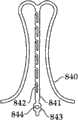
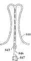
在一个实施方式中,提供了所述多元瓣膜扣与所述人工瓣膜移植装置的控制单元的可逆连接机制。在这一实施方式中,所述人工瓣膜移植装置包括中空的轨迹导管,锁闭和释放单元,弹性拉力调节单元,以及多元瓣膜扣单元。在另一个实施例中,所述弹性拉力调节单元包括远端末梢环(distal loop end)。在另一个实施方式中,所述锁闭和释放单元至少部分地被所述中空轨迹导管包住,且其近端与所述移植装置的控制单元相连。在另一个实施方式中,所述弹性拉力调节单元至少部分地被所述中空轨迹导管包住,且其近端与所述移植装置的控制单元相连。在一个实施方式中,所述弹性拉力调节单元的末端延伸至所述锁闭和释放单元的末端。In one embodiment, a reversible connection mechanism of the multi-valve button and the control unit of the artificial valve transplantation device is provided. In this embodiment, the artificial valve transplantation device includes a hollow trajectory catheter, a locking and releasing unit, an elastic tension adjusting unit, and a multiple valve buckle unit. In another embodiment, the elastic tension adjusting unit includes a distal loop end. In another embodiment, said lock and release unit is at least partially enclosed by said hollow trajectory catheter and its proximal end is connected to a control unit of said grafting device. In another embodiment, the elastic tension adjustment unit is at least partially enclosed by the hollow trajectory catheter, and its proximal end is connected with the control unit of the transplantation device. In one embodiment, the end of the elastic tension adjusting unit extends to the end of the locking and releasing unit.
在一个实施方式中,所述弹性拉力调节单元由形状记忆材料组成。在另一个实施方式中,所述弹性弹力调节单元包括单丝、多丝或辫状的多丝结构。它们的例子包括了金属丝、线或单丝,如用于外科缝合中的这些对象。单丝可以由天然物质制成,如羊肠线、丝绸或亚麻,或者可以是人造材料。例如,不可吸收的缝合单丝可以由尼龙或聚丙烯制成。本领域技术人员应能够根据其性质,如拉伸强度、打结强度、弹性、恢复能力或硬度以及组织反应活性来选择制备弹性拉力调节单元的合适的材料。In one embodiment, the elastic tension adjusting unit is composed of shape memory material. In another embodiment, the elastic elastic adjustment unit comprises monofilament, multifilament or braided multifilament structure. Examples of these include wires, threads or monofilaments, such as those used in surgical sutures. Monofilaments can be made from natural substances such as gut, silk or flax, or they can be man-made. For example, nonabsorbable suture monofilaments can be made from nylon or polypropylene. Those skilled in the art should be able to select suitable materials for preparing the elastic tension adjusting unit according to its properties, such as tensile strength, knot strength, elasticity, recovery ability or hardness, and tissue reactivity.
在一个实施方式中,提供了将多元瓣膜扣单元与人工瓣膜移植装置的控制单元可逆连接的方法。在另一个实施方式中,所述方法包括:1)将弹性拉力调节单元的末梢环端穿过多元瓣膜扣单元分支部的孔中;2)使锁闭和释放单元通过弹性拉力调节单元的末梢环端向末端移动;3)使 中空的轨迹导管向末端移动,直到所述中空轨迹导管至少包住所述弹性拉力调节单元的末梢环端以及一部分所述多元瓣膜扣单元分支部。In one embodiment, a method for reversibly connecting a multi-valve buckle unit with a control unit of a prosthetic valve implantation device is provided. In another embodiment, the method includes: 1) passing the end ring end of the elastic tension adjustment unit through the hole in the branch of the multi-valve buckle unit; 2) passing the locking and releasing unit through the distal end of the elastic tension adjustment unit The ring end moves toward the end; 3) the hollow trajectory catheter is moved toward the end until the hollow trajectory catheter at least wraps the distal ring end of the elastic tension adjustment unit and a part of the multi-valve buckle unit branch.
在一个实施方式中,提供了从人工瓣膜移植装置的控制单元中释放多元瓣膜扣单元的方法。在另一个实施方式中,所述方法包括:1)使中空轨迹导管沿近端方向(proximal direction)移动以露出多元瓣膜扣分支部的近端;2)使锁闭和释放单元沿近端方向移动直到所述锁闭和释放单元不再处于所述弹性拉力调节单元的末梢环端;3)使中空轨迹导管、锁闭和释放单元以及弹性拉力调节单元沿近端方向移动,直到所述弹性拉力调节单元不再处于多元瓣膜扣分支部的孔中。In one embodiment, a method of releasing a multiple valve buckle unit from a control unit of a prosthetic valve implantation device is provided. In another embodiment, the method comprises: 1) moving a hollow trajectory catheter in a proximal direction to expose the proximal ends of the multiple valve clasp branches; 2) moving the lock and release unit in a proximal direction Move until the lock and release unit is no longer at the distal ring end of the elastic tension adjustment unit; 3) move the hollow track catheter, the lock and release unit, and the elastic tension adjustment unit in the proximal direction until the elastic The tension adjusting unit is no longer in the hole of the branch of the multi-valve buckle.
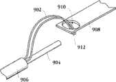
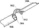
在一个实施方式中,提供了将人工瓣膜装置与多元瓣膜扣单元可逆连接的机制。在该实施方式中,所述机制包括人工瓣膜移植装置,其中,所述移植装置包括锁闭和释放单元,弹性拉力调节单元,中空轨迹导管,多元瓣膜扣单元以及弹性分支部。在一个实施方式中,所述弹性分支部的近端与所述弹性拉力调节单元的末梢环端可逆连接,所述弹性分支部的末端与多元瓣膜扣单元或人工瓣膜支持架可逆或永久相连。在一个实施方式中,所述弹性拉力调节单元的近端与所述人工移植装置的控制单元相连。在一个实施方式中,所述多元瓣膜扣单元包括多个多元单元分支部。在另一个实施方式中,多元瓣膜扣单元不包括多元单元分支部。In one embodiment, a mechanism for reversibly attaching a prosthetic valve device to a multiple valve button unit is provided. In this embodiment, the mechanism includes a prosthetic valve implantation device, wherein the implantation device includes a locking and releasing unit, an elastic tension adjustment unit, a hollow trajectory catheter, a multi-valve buckle unit, and an elastic branch. In one embodiment, the proximal end of the elastic branch part is reversibly connected to the distal ring end of the elastic tension adjustment unit, and the end of the elastic branch part is reversibly or permanently connected to the multi-valve buckle unit or the artificial valve support frame. In one embodiment, the proximal end of the elastic tension adjustment unit is connected with the control unit of the artificial transplantation device. In one embodiment, the multi-component valve button unit includes a plurality of multi-component branch parts. In another embodiment, the multiple valve button unit does not include multiple unit branches.
在一个实施方式中,提供了将多元瓣膜扣单元与所述人工瓣膜移植装置的控制单元可逆连接的方法。在该实施方式中,所述方法包括:1)将弹性分支的近端与弹性拉力调节单元的末梢环端相互扣住;2)使中空轨迹导管沿着末端方向移动,直到中空轨迹导管至少包住弹性分支的近端部。In one embodiment, a method for reversibly connecting the multi-valve buckle unit with the control unit of the artificial valve transplantation device is provided. In this embodiment, the method includes: 1) buckling the proximal end of the elastic branch and the distal ring end of the elastic tension adjustment unit; 2) moving the hollow trajectory catheter along the direction of the end until the hollow trajectory catheter at least covers Hold the proximal end of the elastic branch.
在一个实施方式中,提供了将多元瓣膜扣单元从所述人工瓣膜移植装置的控制单元释放的方法。在该实施方式中,所述方法包括:1)使中空轨迹导管沿近端方向移动,使得中空轨迹导管不包住弹性分支部的近端;2)沿近端方向拉动中空轨迹导管和弹性拉力调节单元,其中,所述弹性分支部伸直,使得弹性分支部不再与弹性拉力调节单元相互扣住。In one embodiment, a method of releasing a multi-valve buckle unit from a control unit of said prosthetic valve implantation device is provided. In this embodiment, the method includes: 1) moving the hollow trajectory catheter in a proximal direction such that the hollow trajectory catheter does not encase the proximal end of the elastic branch; 2) pulling the hollow trajectory catheter and the elastic tension in the proximal direction The adjustment unit, wherein the elastic branch is straightened so that the elastic branch is no longer interlocked with the elastic tension adjustment unit.
在另一方面,还提供了置放人工心脏瓣膜的方法。所述方法包括提供如上述的移植装置,其中,所述人工瓣膜包括至少一个瓣膜扣,其中, 所述至少一个瓣膜扣包括一个U形部和两个分支部;该方法还包括将所述移植装置放入病人的心室;引导移植装置的位置从而使得包住所述至少一个瓣膜扣的第二外壳在病人的心脏内通过并延伸过心脏瓣膜(cardiac valve);控制移植装置以暴露所述至少一个瓣膜扣,并将至少一个瓣膜扣在心脏瓣膜的窦(sinus)中固定;通过控制单元调节人工瓣膜的位置,使得人工瓣膜的远边大致接近于所述至少一个瓣膜扣;沿近端方向滑动第一外壳使人工瓣膜从第一外壳中释放,其中,所述人工瓣膜膨胀至其膨胀状态从而在人工瓣膜支持架和所述至少一个瓣膜扣中夹住心脏瓣膜的组织;从病人体内移除传送装置和导引器。In another aspect, a method of placing a prosthetic heart valve is also provided. The method includes providing a transplantation device as described above, wherein the artificial valve comprises at least one valve buckle, wherein the at least one valve buckle comprises a U-shaped portion and two branch portions; the method further comprises transplanting the The device is placed into the patient's ventricle; the position of the implantation device is guided so that the second housing encasing the at least one valve button passes in the patient's heart and extends through the heart valve (cardiac valve); the implantation device is controlled to expose the at least one valve button. A valve buckle, and at least one valve buckle is fixed in the sinus (sinus) of the heart valve; the position of the artificial valve is adjusted by the control unit, so that the far edge of the artificial valve is roughly close to the at least one valve buckle; along the proximal direction sliding the first housing to release the prosthetic valve from the first housing, wherein the prosthetic valve expands to its expanded state to clamp tissue of the heart valve in the prosthetic valve holder and the at least one valve buckle; Remove conveyors and introducers.
在一个实施方式中,沿近端方向滑动第一外壳包括沿近端方向拉动第一外壳控制器,同时保持人工瓣膜不动。In one embodiment, sliding the first housing in the proximal direction includes pulling the first housing controller in the proximal direction while holding the prosthetic valve stationary.
在一个实施方式中,所述移植装置通过导入器放入,所述导入器事先放入病人的左心室。In one embodiment, the graft device is placed through an introducer that was previously placed into the patient's left ventricle.
在另一个实施方式中,提供移植装置的步骤包括了提供一种移植装置,其中,所述至少一个瓣膜扣被包在所述移植装置的第二外壳内。在另一个实施方式中,引导移植装置包括了引导移植装置从而使得第二外壳通过并延伸过病患的心脏瓣膜。在另一个实施方式中,所述第二外壳位于心脏的左心房。In another embodiment, the step of providing a graft device includes providing a graft device, wherein said at least one valve button is enclosed within a second housing of said graft device. In another embodiment, guiding the grafting device includes guiding the grafting device such that the second housing passes through and extends past the patient's heart valve. In another embodiment, the second housing is located in the left atrium of the heart.
在一个实施方式中,控制移植装置以暴露所述至少一个瓣膜扣包括了控制移植装置以移动第二外壳,从而暴露至少一个瓣膜扣。在另一个实施方式中,控制移植装置以移动第二外壳从而暴露至少一个瓣膜扣包括了沿着近端方向拉动第二外壳控制器,并同时保持至少一个瓣膜扣不动。In one embodiment, controlling the graft device to expose the at least one valve button comprises controlling the graft device to move the second housing to expose the at least one valve button. In another embodiment, controlling the graft device to move the second housing to expose the at least one valve button comprises pulling the second housing controller in a proximal direction while holding the at least one valve button in place.
在一个实施方式中,在露出至少一个瓣膜扣之前,使用了成像系统来定位传送装置的第一和第二外壳。In one embodiment, an imaging system is used to position the first and second housings of the delivery device prior to exposing the at least one valve button.
在一个实施方式中,所述方法包括置放人工瓣膜,其中,所述人工瓣膜为主动脉人工瓣膜。在另一个实施方式中,所述方法包括将移植装置通过病人的胸腹区域放入并使顶端或接近顶端部进入左心室。In one embodiment, the method includes placing a prosthetic valve, wherein the prosthetic valve is an aortic prosthetic valve. In another embodiment, the method includes placing the graft device through the thoracoabdominal region of the patient and entering the apical or near-apical portion into the left ventricle.
在一个实施方式中,所述方法进一步包括将第二外壳前移通过主动脉瓣口进入左心房,并使第一外壳接近主动脉瓣口;使第二外壳沿末端 方向前移以露出至少一个瓣膜扣,其中,所述至少一个瓣膜扣在左心房内径向膨胀;拉回第二外壳控制器,直到所述至少一个瓣膜扣的U形部接触到主动脉窦;使第一外壳前移,直到所述第一外壳的末端大致接近于第二外壳的近端,或直到所述第一外壳的末端与主动脉瓣口相接触;拉回所述第一外壳,同时保持人工瓣膜不动,以露出并置放人工瓣膜;沿近端方向移动所述至少一个轨迹导管的释放开关,同时保持锁线不动,从而从所述至少一个轨迹导管中释放所述至少一个瓣膜扣的分支部;沿近端方向移动所述推进索控制器以从人工瓣膜中释放所述至少一个推进索啮合器;使第一外壳沿末端方向前移直到第一外壳的远端与第二外壳的近端相接触;拉回传送装置以从病人体内移除传送装置。In one embodiment, the method further comprises advancing the second housing through the aortic valve orifice into the left atrium and proximate the first housing to the aortic valve orifice; advancing the second housing distally to expose at least one the valve buckle, wherein the at least one valve buckle is radially expanded within the left atrium; the second housing controller is pulled back until the U-shaped portion of the at least one valve buckle contacts the aortic sinus; the first housing is advanced, until the end of the first housing is approximately proximal to the proximal end of the second housing, or until the end of the first housing contacts the aortic valve orifice; pulling back the first housing while holding the prosthetic valve in place, to expose and place the prosthetic valve; move the release switch of the at least one trajectory catheter in a proximal direction while keeping the locking wire stationary, thereby releasing the branch of the at least one valve buckle from the at least one trajectory catheter; Moving the pusher cable controller in a proximal direction to release the at least one pusher cable engager from the prosthetic valve; moving the first housing in a distal direction until the distal end of the first housing is aligned with the proximal end of the second housing Contact; pull back on the delivery device to remove it from the patient.
在一个实施方式中,所述方法包括置放人工瓣膜,其中,所述人工瓣膜为肺动脉瓣膜。在另一个实施方式中,所述方法包括通过病人的股静脉放入传送装置,使传送装置前移通过下腔静脉并进入右心房。In one embodiment, the method includes placing a prosthetic valve, wherein the prosthetic valve is a pulmonary valve. In another embodiment, the method includes placing the delivery device through the patient's femoral vein, advancing the delivery device through the inferior vena cava and into the right atrium.
在一个实施方式中,所述方法进一步包括使第二外壳前移通过三尖瓣环进入右心室,使第二外壳前移通过肺动脉瓣环并将第二外壳置于肺动脉;使第二外壳沿末端方向前移以露出所述至少一个瓣膜扣,其中,所述至少一个瓣膜扣在肺动脉中径向膨胀;拉回第二外壳控制器,直到所述至少一个瓣膜扣的U形部与肺窦接触;使第一外壳前移,直到第一外壳的末端大致接近于第二外壳的末端,或者直到第一外壳的末端与主动脉瓣口接触;拉回第一外壳,同时保持人工瓣膜不动,以露出并置放人工瓣膜;向近端方向移动所述至少一个轨迹导管释放开关,同时保持锁线不动,从而从所述至少一个轨迹导管中释放所述至少一个瓣膜扣的分支部;向近端方向移动推进索控制器,以从所述人工瓣膜中释放所述至少一个推进索啮合器;使第一外壳沿末端方向前移,直到第一外壳的远端与第二外壳的近端相接触;拉回传送装置以从病人体内移除传送装置。In one embodiment, the method further comprises advancing the second housing through the tricuspid annulus into the right ventricle, advancing the second housing through the pulmonary annulus and placing the second housing over the pulmonary artery; The distal direction is moved forward to expose the at least one valve buckle, wherein the at least one valve buckle is radially expanded in the pulmonary artery; the second housing controller is pulled back until the U-shaped portion of the at least one valve buckle is in contact with the pulmonary sinuses Contact; advance the first housing until the end of the first housing is approximately close to the end of the second housing, or until the end of the first housing contacts the aortic valve orifice; pull back the first housing while holding the prosthetic valve in place , to expose and place the prosthetic valve; move the at least one trajectory catheter release switch in a proximal direction while keeping the locking wire stationary, thereby releasing the branch of the at least one valve buckle from the at least one trajectory catheter; moving the pusher cable controller in the proximal direction to release the at least one pusher cable engager from the prosthetic valve; the first shell is moved forward in the distal direction until the distal end of the first shell is in contact with the proximal end of the second shell; end contact; pull the delivery device back to remove the delivery device from the patient.
在一个实施方式中,所述方法包括置放人工瓣膜,其中,所述人工瓣膜为二尖瓣膜。在另一个实施方式中,所述方法包括通过病人的股静脉放入传送装置,使移植装置前移通过下腔静脉并进入右心房。In one embodiment, the method includes placing a prosthetic valve, wherein the prosthetic valve is a mitral valve. In another embodiment, the method includes placing the delivery device through the patient's femoral vein, advancing the graft device through the inferior vena cava and into the right atrium.
在一个实施方式中,所述方法进一步包括使移植装置的远端前移, 通过三尖瓣环进入右心室,越隔穿刺(transeptal puncture);使移植装置的远端前移,通过左心房和二尖瓣环,将第二外壳置于左心室内,将第一外壳置于左心房内;使第二外壳沿末端方向前移,以露出所述至少一个瓣膜扣,其中,所述至少一个瓣膜扣在左心室中径向膨胀;拉回第二外壳控制器,直到所述至少一个瓣膜扣的U形部与二尖瓣环接触;使第一外壳前移,直到第一外壳的末端大致接近于第二外壳的近端,或者直到第一外壳的末端与二尖瓣环接触;拉回第一外壳,同时保持人工瓣膜不动,以露出并置放人工瓣膜;向近端方向移动所述至少一个轨迹导管的释放开关,同时保持锁线不动,从而从所述至少一个轨迹导管中释放所述至少一个瓣膜扣的分支部;沿近端方向移动推进索控制器,从而使所述至少一个推进索啮合器与人工瓣膜脱离;使第一外壳沿远端方向前移,直到第一外壳的远端与第二外壳的近端相接触;拉回传送装置以从病人体内移除传送装置。In one embodiment, the method further comprises advancing the distal end of the graft device through the tricuspid annulus into the right ventricle, transeptal puncture; advancing the distal end of the graft device through the left atrium and mitral annulus, place the second shell in the left ventricle, place the first shell in the left atrium; move the second shell forward in the distal direction to expose the at least one valve button, wherein the at least one The valve buckle is radially expanded in the left ventricle; the second housing controller is pulled back until the U-shaped portion of the at least one valve buckle contacts the mitral valve annulus; the first housing is advanced until the end of the first housing is approximately close to the proximal end of the second housing, or until the end of the first housing contacts the mitral annulus; pull back the first housing while holding the prosthetic valve in place to expose and place the prosthetic valve; move the prosthetic valve in a proximal direction the release switch of the at least one trajectory catheter while keeping the lock wire stationary, thereby releasing the branch of the at least one valve button from the at least one trajectory catheter; moving the advancement cable controller in the proximal direction, thereby causing the At least one advance cable engager is disengaged from the prosthetic valve; the first housing is advanced in a distal direction until the distal end of the first housing contacts the proximal end of the second housing; the delivery device is pulled back to remove the delivery device from the patient device.
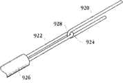
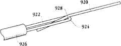
在另一方面,还提供了对病人传送医学瓣膜的装置。所述装置包括管状操纵线,所述操纵线由装置的末端延伸至装置的近端,所述装置还包括位于装置近端的控制单元,包括中空(open lumen)的第一外壳,所述第一外壳位于相对于的控制单元的远端,所述装置还包括至少一个轨迹导管,所述轨迹导管具有与控制单元相连的近端以及用于接触和控制医学瓣膜的末端,所述装置还包括推进索,所述推进索的近端与所述控制的单元固定,其远端用于可控接触所述医学瓣膜。In another aspect, an apparatus for delivering a medical valve to a patient is also provided. The device comprises a tubular manipulation wire extending from a distal end of the device to a proximal end of the device, the device also comprises a control unit located at the proximal end of the device, comprising a first shell of a hollow (open lumen), the first A housing is located at the distal end relative to the control unit, the device also includes at least one trajectory catheter having a proximal end connected to the control unit and a distal end for contacting and controlling the medical valve, the device further comprising A propelling cable, the proximal end of which is fixed to the control unit, and the distal end of which is used to controllably contact the medical valve.
在一个实施方式中,所述控制单元包括推进索控制器和轨迹导管控制器,其中,所述推进索控制器和轨迹导管控制器各自独立可控。In one embodiment, the control unit comprises a propulsion cable controller and a trajectory catheter controller, wherein each of the propulsion cable controller and the trajectory catheter controller is independently controllable.
在另一个实施方式中,所述至少一个轨迹导管的近端与轨迹导管控制器中的释放开关相连。In another embodiment, the proximal end of the at least one trajectory catheter is connected to a release switch in the trajectory catheter controller.
在另一个实施方式中,所述至少一个推进索的近端与推进索控制器中的可移动控制器相连。In another embodiment, the proximal end of the at least one push cable is connected to a moveable controller in the push cable controller.
在另一方面,还提供了置放人工心脏瓣膜的方法。所述方法包括提供如上所述的移植装置;将移植装置放入病人的心脏中;控制移植装置的位置,使得包住人工瓣膜的第二外壳大致位于天然瓣膜内;操纵移植装置以暴露所述至少一个瓣膜扣的U形部的弯曲部,暴露所述U形部的 笔直部以及所述至少一个轨迹导管的远端部分,从而允许所述至少一个瓣膜扣径向膨胀进入啮合位置;将所述至少一个瓣膜扣定位于心脏瓣膜的窦中;沿远端方向滑动第二外壳以从第二外壳中释放至少一部分人工瓣膜支持架;沿远端方向滑动第二外壳以从第二外壳中释放全部人工瓣膜支持架,其中,所述人工瓣膜膨胀至其膨胀状态,从而在人工瓣膜支持架和所述至少一个瓣膜扣之间夹住天然心脏瓣膜的组织;从病人体内移除传送装置和导引器。In another aspect, a method of placing a prosthetic heart valve is also provided. The method includes providing a graft device as described above; placing the graft device in a patient's heart; controlling the position of the graft device such that a second shell enclosing the prosthetic valve is substantially within the native valve; manipulating the graft device to expose the The curved portion of the U-shaped portion of the at least one valve buckle, exposing the straight portion of the U-shaped portion and the distal portion of the at least one trajectory catheter, thereby allowing the radial expansion of the at least one valve buckle into an engaged position; The at least one valve buckle is positioned in the sinus of the heart valve; sliding the second housing in a distal direction to release at least a portion of the prosthetic valve holder from the second housing; sliding the second housing in a distal direction to release from the second housing an entire prosthetic valve support, wherein the prosthetic valve expands to its expanded state so as to sandwich tissue of the native heart valve between the prosthetic valve support and the at least one valve buckle; removal of the delivery device and guide from the patient Primer.
在该实施方式中,所述天然的心脏瓣膜小叶向着进入心室的移植装置的末端弯曲。In this embodiment, the native heart valve leaflets are curved towards the end of the graft device into the ventricle.
在一个实施方式中,控制移植装置以露出所述至少一个瓣膜扣的U形部的弯曲部,包括了使第二外壳向远端方向移动。在另一个实施方式中,露出所述至少一个瓣膜扣的笔直部以及所述至少一个轨迹导管的至少一个远端部分,包括了使轨迹导管控制单元向着末端方向移动,同事保持第一外壳不动。In one embodiment, controlling the grafting device to expose the bend of the U-shaped portion of said at least one valve button comprises moving the second housing in a distal direction. In another embodiment, exposing the straight portion of the at least one valve button and the at least one distal portion of the at least one trajectory catheter comprises moving the trajectory catheter control unit toward the distal end while keeping the first housing stationary .
在一个实施方式中,向远端方向滑动第二外壳包括了向远端方向推动第二外壳控制索,同时保持传送装置不动。In one embodiment, sliding the second housing in the distal direction includes pushing the second housing control wire in the distal direction while holding the delivery device stationary.
在一个实施方式中,将移植装置放入心脏包括了将移植装置放入股动脉,以及使移植装置通过主动脉弓前移进入左心房。在该实施方式中,所述人工心脏瓣膜为主动脉人工心脏瓣膜。In one embodiment, placing the graft device into the heart comprises placing the graft device into the femoral artery, and advancing the graft device through the aortic arch into the left atrium. In this embodiment, the artificial heart valve is an aortic artificial heart valve.
在一个实施方式中,将移植装置放入心脏包括了通过事先放入病人左心室的导入器将移植装置放入,并且使移植装置向着左心室前移。在该实施方式中,所述人工心脏瓣膜为人工二尖瓣膜。In one embodiment, placing the graft device into the heart includes placing the graft device through an introducer previously placed in the patient's left ventricle, and advancing the graft device toward the left ventricle. In this embodiment, the artificial heart valve is an artificial mitral valve.
在另一方面,提供了移植装置,包括包含了多个小叶的弹性框架(framework);还包括多个可移动地连接在所述弹性框架上的多个瓣膜扣,其中,所述瓣膜扣包括扣耳(clasper ear)和两个扣轴(clasper shaft);还包括包住压缩状态的弹性框架的第一外壳;包住多个压缩状态的瓣膜扣的第二外壳;位于所述第二外壳内的瓣膜扣推动器和位于所述第一外壳内的瓣膜塞(valve stopper);其中,在瓣口内置放弹性框架前,所述第一外壳位于第二外壳的远端。In another aspect, a transplantation device is provided, comprising an elastic frame comprising a plurality of leaflets; and a plurality of valve buttons movably connected to the elastic frame, wherein the valve buttons include Buckle ear (clasper ear) and two buckle axles (clasper shaft); Also comprise the first shell that encases the elastic frame of compressed state; Enclose the second shell of the valve clasp of a plurality of compressed states; Located in said second shell The valve buckle pusher in the valve and the valve stopper (valve stopper) in the first shell; wherein, before the elastic frame is placed in the valve mouth, the first shell is located at the far end of the second shell.
在另一方面,提供了置放人工心脏瓣膜的方法。所述方法包括提供 如上所述的心脏移植装置,将移植装置放入股动脉以及引导移植装置通过股动脉进入左心室直到第一外壳位于左心室的瓣口且第二外壳位于左心房;向近端方向滑动第二外壳以露出多个瓣膜扣,使得扣耳在左心房内径向延伸;向末端推动瓣膜扣直到扣耳接触到主动脉瓣膜窦(aorticvalve sinus);沿末端方向滑动第一外壳以露出弹性框架,使得弹性框架径向延伸以形成膨胀的弹性框架,且每个天然心脏瓣膜被夹在扣耳和扩展后的弹性框架之间。In another aspect, a method of placing a prosthetic heart valve is provided. The method includes providing a cardiac graft device as described above, placing the graft device into the femoral artery and guiding the graft device through the femoral artery into the left ventricle until the first housing is positioned at the valve orifice of the left ventricle and the second casing is positioned at the left atrium; proximally Slide the second housing endwise to expose a plurality of valve buttons such that the button ears extend radially within the left atrium; push the valve button distally until the button ears touch the aortic valve sinus; slide the first housing terminally to The elastic frame is exposed such that the elastic frame radially extends to form an expanded elastic frame, and each natural heart valve is sandwiched between the buckle ears and the expanded elastic frame.
除上述示例性的方面和实施方式以外,本发明其他方面及实施方式将在以下附图和说明书中进一步介绍。In addition to the exemplary aspects and embodiments described above, other aspects and embodiments of the present invention will be further described in the following drawings and descriptions.
附图说明Description of drawings
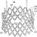
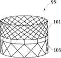
图1A为具有多个瓣膜扣的人工瓣膜支持架的一个实施例的透视图。Figure 1A is a perspective view of one embodiment of a prosthetic valve support with multiple valve buttons.
图1B为具有多个瓣膜扣的人工瓣膜支持架的一个实施例的透视图。Figure IB is a perspective view of one embodiment of a prosthetic valve support with multiple valve buttons.
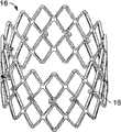
图1C为人工心脏瓣膜支持架的一个实施例的透视图。Figure 1C is a perspective view of one embodiment of a prosthetic heart valve support.
图1D示出了部分膨胀状态的人工瓣膜支持架的一个实施例。Figure ID illustrates one embodiment of a prosthetic valve support in a partially expanded state.
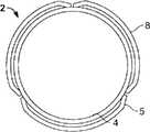
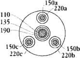
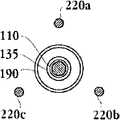
图1E为具有多个瓣膜扣的人工瓣膜支持架的一个实施例的俯视图。Figure IE is a top view of one embodiment of a prosthetic valve support with multiple valve buttons.
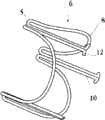
图2A和2B为多个具有棘爪的瓣膜扣的透视图。2A and 2B are perspective views of a plurality of valve buttons with detents.
图3A为具有多个瓣膜扣和一个外层的人工瓣膜支持架的展开平面。Figure 3A is a plan of deployment of a prosthetic valve support frame with valve buttons and an outer layer.
图3B为具有多个瓣膜扣、啮合扣(engagement fastener)和一个外层的人工瓣膜支持架的展开平面。Figure 3B is a plan of deployment of a prosthetic valve support with multiple valve buttons, engagement fasteners and an outer layer.
图4A-4D为可移动地连接了瓣膜扣的人工瓣膜支持架的俯视图,其中,所述支持架为压缩状态(图4A和4C)或膨胀状态(图4B和4D)。4A-4D are top views of a prosthetic valve holder movably connected to a valve buckle, wherein the holder is in a compressed state (FIGS. 4A and 4C) or an expanded state (FIGS. 4B and 4D).
图4E和4F为压缩状态(图4E)或膨胀状态(4F)的具有啮合扣的人工瓣膜支持架的俯视图。4E and 4F are top views of a prosthetic valve holder with engaging buckles in a compressed state (FIG. 4E) or an expanded state (4F).
图5A为可移动连接于压缩状态的人工瓣膜支持架结构的瓣膜扣的截面图,其中,顶端部连接了分支部和U形部。所述瓣膜扣处于啮合位置。Fig. 5A is a cross-sectional view of a valve buckle movably connected to a prosthetic valve support structure in a compressed state, wherein the top end is connected with a branch portion and a U-shaped portion. The valve clasp is in an engaged position.
图5B为可移动连接于压缩状态的人工瓣膜支持架结构的瓣膜扣的截面图,其中,顶端部连接了分支部和U形部。所述瓣膜扣处于嵌套位置。Fig. 5B is a cross-sectional view of the valve buckle movably connected to the prosthetic valve support structure in the compressed state, wherein the top end connects the branch part and the U-shaped part. The valve clasp is in a nested position.
图5C为可移动连接于膨胀状态的人工瓣膜支持架结构的瓣膜扣的截面图,其中,顶端部连接了分支部和U形部。Fig. 5C is a cross-sectional view of the valve buckle movably connected to the prosthetic valve support structure in the expanded state, wherein the top end connects the branch part and the U-shaped part.
图5D为可移动连接于具有啮合扣并处于压缩状态的人工瓣膜支持架结构的瓣膜扣的截面图。所述瓣膜扣处于啮合位置。5D is a cross-sectional view of a valve button removably attached to a prosthetic valve support structure having an engaging button and in a compressed state. The valve clasp is in an engaged position.
图5E为可移动连接于具有啮合扣并处于压缩状态的人工瓣膜支持架结构的瓣膜扣的截面图。所述瓣膜扣处于嵌套位置。5E is a cross-sectional view of a valve button removably attached to a prosthetic valve support structure having an engaging button and in a compressed state. The valve clasp is in a nested position.
图5F为可移动连接于具有啮合扣并处于膨胀状态的人工瓣膜支持架结构的瓣膜扣的截面图。5F is a cross-sectional view of a valve button removably connected to a prosthetic valve support structure having an engaged button and in an expanded state.
图5G为可移动连接于处于压缩状态的人工瓣膜支持架结构的瓣膜扣的一个实施例的截面图。所述瓣膜扣处于啮合位置。5G is a cross-sectional view of one embodiment of a valve buckle removably attached to a prosthetic valve support structure in a compressed state. The valve clasp is in an engaged position.
图5H为可移动连接于处于膨胀状态的人工瓣膜支持架结构的瓣膜扣的一个实施例的截面图。所述瓣膜扣处于嵌套位置。5H is a cross-sectional view of one embodiment of a valve buckle removably attached to a prosthetic valve support structure in an expanded state. The valve clasp is in a nested position.
图5I为可移动连接于处于压缩状态的人工瓣膜支持架结构的瓣膜扣的一个实施例的截面图。Figure 5I is a cross-sectional view of one embodiment of a valve buckle removably attached to a prosthetic valve support frame structure in a compressed state.
图5J为可移动连接于处于压缩状态的人工瓣膜支持架结构的瓣膜扣的一个实施例的截面图。所述瓣膜扣处于啮合位置。5J is a cross-sectional view of one embodiment of a valve buckle removably attached to a prosthetic valve support frame structure in a compressed state. The valve clasp is in an engaged position.
图5K为可移动连接于处于膨胀状态的人工瓣膜支持架结构的瓣膜扣的一个实施例的截面图。所述瓣膜扣处于嵌套位置。5K is a cross-sectional view of one embodiment of a valve buckle removably attached to a prosthetic valve support structure in an expanded state. The valve clasp is in a nested position.
图5L为可移动连接于处于压缩状态的人工瓣膜支持架结构的瓣膜扣的一个实施例的截面图。5L is a cross-sectional view of one embodiment of a valve buckle removably attached to a prosthetic valve support frame structure in a compressed state.
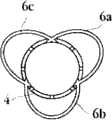
图6A示出了人工瓣膜支持架的展开平面,具有多个固定于支持架的瓣膜扣,多个瓣膜小叶缝合线和一个外层。Figure 6A shows the deployment plane of the prosthetic valve support frame with valve buttons secured to the support frame, valve leaflet sutures and an outer layer.
图6B为具有多个瓣膜扣的人工瓣膜支持架的俯视图,其中,所述多个瓣膜扣固定于支持架上,瓣膜扣支持架为压缩状态。Fig. 6B is a top view of the artificial valve support frame with a plurality of valve buckles, wherein the plurality of valve buckles are fixed on the support frame, and the valve buckle support frame is in a compressed state.
图6C为具有多个瓣膜扣的人工瓣膜支持架的俯视图,其中,所述多个瓣膜扣固定于支持架上,瓣膜扣支持架为膨胀状态。Fig. 6C is a top view of the artificial valve support frame with a plurality of valve buckles, wherein the multiple valve buckles are fixed on the support frame, and the valve buckle support frame is in an expanded state.
图7A示出了具有外层的人工瓣膜,其中,支持架为压缩状态,瓣膜扣为嵌套位置。Figure 7A shows a prosthetic valve with an outer layer, with the support frame in a compressed state and the valve buckle in a nested position.
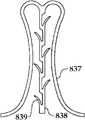
图7B示出了配置于天然心脏瓣膜内的具有可移动连接的瓣膜扣的 人工瓣膜。Figure 7B shows a prosthetic valve with a removably attached valve buckle deployed within a native heart valve.
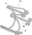
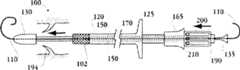
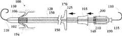
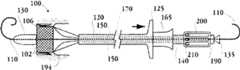
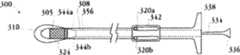
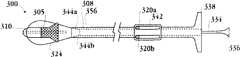
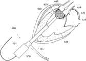
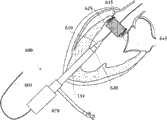
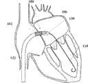
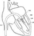
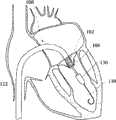
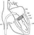
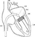
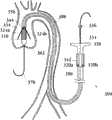
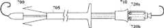
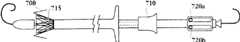
图8A-8H示出了移植装置以及在天然心脏瓣膜内移植人工瓣膜的方法的一个实施例。8A-8H illustrate one embodiment of an implantation device and method of implanting a prosthetic valve within a native heart valve.
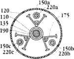
图9A-9Q提供了移植装置的一个实施例的更多截面图,包括示出了移植装置内部不同移植装置部件的位置的横截面图。9A-9Q provide more cross-sectional views of one embodiment of a graft device, including cross-sectional views showing the location of various graft device components within the graft device.
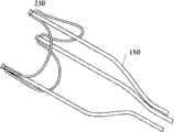
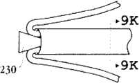
图10A-10C示出了将轨迹导管与瓣膜扣连接的不同实施例。10A-10C illustrate different embodiments of connecting a trajectory catheter to a valve buckle.
图11A-11B示出了具有控制单元的人工瓣膜传送装置的一个实施例,其中,瓣膜扣为压缩状态(图11A)和膨胀状态(图11B)。11A-11B illustrate one embodiment of a prosthetic valve delivery device with a control unit, with the valve buckle in a compressed state (FIG. 11A) and an expanded state (FIG. 11B).
图11C示出了移植装置控制单元的一个实施例。Figure 11C illustrates one embodiment of a transplantation device control unit.
图12A示出了人工瓣膜移植装置的一个实施例。Figure 12A shows one embodiment of a prosthetic valve implantation device.
图12B-12D提供了人工瓣膜移植装置的一个实施例的横截面图。12B-12D provide cross-sectional views of one embodiment of a prosthetic valve graft device.
图13A-13D提供了移植装置的一个实施例的详细截面。13A-13D provide detailed cross-sections of one embodiment of a graft device.
图14A-14D示出了移植装置的一个实施例的控制步骤。14A-14D illustrate the control steps of one embodiment of a grafting device.
图15A-15C示出了移植装置的一个实施例的控制步骤。15A-15C illustrate the control steps of one embodiment of a grafting device.
图16A-16C示出了人工瓣膜支持架的可选实施例。16A-16C illustrate an alternative embodiment of a prosthetic valve holder.
图17A-17B示出了多元瓣膜扣单元的可选实施例。17A-17B illustrate an alternative embodiment of a multiple valve button unit.
图17C-17G示出了多元瓣膜扣分支部的可选实施例。Figures 17C-17G illustrate alternative embodiments of multiple valve clasp branches.
图17H-17M示出了多元瓣膜扣分支部的可选实施例。17H-17M illustrate alternative embodiments of multiple valve clasp branches.
图18A-18B示出了多元瓣膜扣单元的可选实施例。18A-18B illustrate an alternative embodiment of a multiple valve button unit.
图18C示出了多元瓣膜扣分支部的可选实施例。Figure 18C shows an alternative embodiment of multiple valve clasp branches.
图19A-19E示出了在多元瓣膜扣单元分支上可逆连接瓣膜传送装置的方式的可选实施例。Figures 19A-19E illustrate alternative embodiments of the manner in which a valve delivery device is reversibly attached to branches of multiple valve button units.
图20A-20C示出了在多元瓣膜扣单元分支上释放瓣膜移植装置的方式的可选实施例。Figures 20A-20C illustrate an alternative embodiment of a manner of releasing a valve graft device on branches of multiple valve button units.
图21A-21C示出了在多元瓣膜扣单元的分支部上可逆连接瓣膜传送装置的方式的可选实施例。Figures 21A-21C illustrate an alternative embodiment of the manner in which a valve delivery device is reversibly attached to the branches of a multi-valve button unit.
图22A-22D示出了从多元瓣膜扣单元分支上释放瓣膜移植装置的方式的可选实施例。Figures 22A-22D illustrate an alternative embodiment of a manner of releasing a valve graft device from branches of a multiple valve button unit.
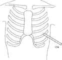
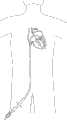
图23示出了将导入器放入胸腹区域。Figure 23 shows placement of the introducer in the thoracoabdominal region.
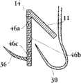
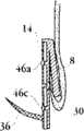
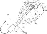
图24A-24H示出了主动脉瓣膜置换的经心尖手术。24A-24H illustrate a transapical procedure for aortic valve replacement.
图25A-25L示出了移植装置以及在天然心脏二尖瓣膜内移植人工二尖瓣膜的方法。25A-25L illustrate the implantation device and method of implanting a prosthetic mitral valve within a native cardiac mitral valve.
图26示出了传送心脏瓣膜的路径,包括使移植装置通过下腔静脉前移。Figure 26 shows the approach for delivery of a heart valve including advancing the graft device through the inferior vena cava.
图27示出了传送心脏瓣膜的路径,包括将移植装置导入颈静脉并使装置通过上腔静脉前移。Figure 27 shows the approach for delivery of the heart valve, including introducing the graft device into the jugular vein and advancing the device through the superior vena cava.
图28示出了传送人工肺动脉瓣膜的路径,包括了将移植装置导入颈静脉并且使装置通过上腔静脉前移。Figure 28 shows the route for delivering a prosthetic pulmonary valve including introducing the graft device into the jugular vein and advancing the device through the superior vena cava.
图29A-29H示出了用于移植人工主动脉瓣膜的移植装置的一个实施例的方法,包括使移植装置通过股动脉和主动脉弓前移。29A-29H illustrate a method of one embodiment of a graft device for implanting an aortic valve prosthesis including advancing the graft device through the femoral artery and aortic arch.
图30A-30C示出了传送和置放人工瓣膜的可选实施例。30A-30C illustrate an alternative embodiment for delivery and placement of a prosthetic valve.
图31A-31D示出了置放和脱离人工主动脉瓣膜的一个方法Figures 31A-31D illustrate a method of placement and detachment of a prosthetic aortic valve
发明详述Detailed description of the invention
本发明提供了人工置换,特别是采用最小限度创伤外科技术人工置换瓣膜的装置、系统和方法。虽然该装置和方法可应用于身体不同部分的不同血管中,但是它们特别适用于置换功能障碍的心脏瓣膜,特别是主动脉瓣膜、肺动脉瓣膜或二尖瓣膜。所述装置和方法特别的优势在于能够提供更灵活的心脏瓣膜支架传送装置,保证人工心脏瓣膜的精确置换,减少对成像的依赖,并提供对人工瓣膜额外的加固,减少瓣膜移动的发生。另一个优点是如下所述的无缝线人工瓣膜的传送和移植。The present invention provides devices, systems and methods for artificial replacement, particularly valve replacement using minimally invasive surgical techniques. Although the devices and methods can be applied in different blood vessels in different parts of the body, they are particularly useful for replacing dysfunctional heart valves, particularly the aortic, pulmonary or mitral valves. The particular advantage of the device and method is that it can provide a more flexible heart valve stent delivery device, ensure accurate replacement of the artificial heart valve, reduce dependence on imaging, provide additional reinforcement for the artificial valve, and reduce the occurrence of valve movement. Another advantage is the delivery and implantation of a sutureless prosthetic valve as described below.
本发明还提供了改进的移植人工心脏瓣膜的装置和方法。特别是改进的最小限度创伤方法和装置,用于在心脏内瓣膜解剖位置内或邻近瓣膜解剖位置的顺行(antegrade)、经皮(percutaneous)或经股动脉导管介入(femoral transcatheter)移植可膨胀的人工心脏瓣膜。特别地,本发明所述改进的人工心脏瓣膜装置和方法为瓣膜传送步骤提供了更好的灵活性,保证人工心脏瓣膜更精准的传送,减少对成像的依赖,并提供对人工瓣膜额外的加固,减少瓣膜移动或位移的发生。The present invention also provides an improved device and method for implanting a prosthetic heart valve. In particular, improved minimally invasive methods and devices for antegrade, percutaneous, or femoral transcatheter implantation of expandable artificial heart valve. In particular, the improved artificial heart valve device and method of the present invention provides better flexibility for the valve delivery step, ensures more accurate delivery of the artificial heart valve, reduces reliance on imaging, and provides additional reinforcement for the artificial valve , to reduce the occurrence of valve movement or displacement.
一个置放主动脉瓣膜的方法包括将瓣膜移植系统放入病人或受体肋骨间,使其进入左心室的顶端,然后使人工瓣膜到达病人的病患瓣膜(经 心尖传送transapical delivery)。采用主动脉瓣膜的另一个方法通常包括通过股动脉(股动脉传送)到达主动脉。One approach to aortic valve placement involves placing the valve graft system between the patient's or recipient's ribs, allowing it to access the apex of the left ventricle, and then bringing the prosthetic valve to the patient's diseased valve (transapical delivery). Another approach using the aortic valve usually involves accessing the aorta through the femoral artery (femoral delivery).
置放肺动脉或二尖瓣膜的方法通常包括将瓣膜传送系统放入颈静脉,然后引导该系统通过上腔静脉进入右心房。所述装置可以继续前移进入右心室和肺动脉瓣膜。或者,所述装置可以通过房间隔穿刺进入左心房,之后前移进入二尖瓣膜。The approach to pulmonary or mitral valve placement usually involves placing the valve delivery system in the jugular vein and then guiding the system through the superior vena cava into the right atrium. The device can continue to advance into the right ventricle and pulmonary valve. Alternatively, the device may be punctured through the septum into the left atrium and then advanced into the mitral valve.
另一种置放肺动脉或二尖瓣膜的方法通常包括将瓣膜移植系统放入股动脉,之后引导该系统通过上腔静脉进入右心房,然后如上所述使该装置前移至肺动脉或二尖瓣膜。Another method of placing the pulmonary or mitral valve usually involves placing a valve graft system into the femoral artery, then guiding the system through the superior vena cava into the right atrium, and then advancing the device to the pulmonary artery or mitral valve as described above .
所述瓣膜传送系统或移植装置的尺寸和长度足以通过病人身体的第一开口(如主动脉或股动脉或静脉入口),通过病人的主动脉、股动脉或静脉。所述移植装置也可由经胸端口进入病人胸腹(如肋间)区域并在心尖附近进入左心房。根据不同的实施方式,所述经胸端口为引导管(introducer)、套管针或套管,是本领域熟知的。The size and length of the valve delivery system or implantation device is sufficient to pass through a first opening in the patient's body, such as an aortic or femoral artery or venous access, through the patient's aorta, femoral artery or vein. The grafting device may also be accessed through a thoracic port into the patient's thoracoabdominal (eg, intercostal) region and into the left atrium near the apex of the heart. According to different embodiments, the transthoracic port is an introducer, a trocar or a cannula, which are well known in the art.
至少一个传送壳或导管沿着导丝(guidewire)通过主动脉、二尖瓣或肺动脉瓣膜。这些方法在以下内容中记载,并参考下述的人工瓣膜和传送装置。本领域的技术人员应理解,其他在此记载的置放人工瓣膜的方法也可以使用。At least one delivery sheath or catheter is passed along a guidewire through the aortic, mitral or pulmonary valve. These methods are described below, with reference to the prosthetic valves and delivery devices described below. Those skilled in the art will appreciate that other methods of placing prosthetic valves described herein may also be used.
入口包括一个或多个止血阀(hemostasis valve)或止血封口。所述止血阀或封口被用于提供防止移植过程中的失血或渗漏的密封,并可以用在心尖、主动脉或二者均可。所述入口配置允许移植装置、导管或任何需传送的工具或装置通过并到达目标位置,同时也提供防止失血或渗漏的密封。这些方法在本领域是熟知的。The inlet includes one or more hemostasis valves or hemostasis seals. The hemostatic valve or seal is used to provide a seal against blood loss or leakage during grafting and may be used at the apex, aorta, or both. The inlet configuration allows passage of a graft device, catheter, or any tool or device to be delivered to the target site, while also providing a seal against blood loss or leakage. These methods are well known in the art.
所述装置和方法可以用于包括人类和其他哺乳动物的主体上,所述其它哺乳动物包括但不限于:鼠、兔、猪、狗、羊和马。The devices and methods may be used on subjects including humans and other mammals including, but not limited to, mice, rabbits, pigs, dogs, sheep, and horses.
以下将记载一系列本发明的实施方式,并参考附图。应理解的是,任意实施例的不同部件可以用于一个或多个其他的实施例中,因此它们的组合也属于本发明权利要求限定的范围内。A series of embodiments of the present invention will be described below with reference to the accompanying drawings. It should be understood that different components of any embodiment can be used in one or more other embodiments, and thus their combinations also fall within the scope of the claims of the present invention.
具体实施方式Detailed ways
I人工瓣膜I prosthetic valve
在第一方面,根据图1A,提供了一个人工瓣膜2,在一优选的实施例中为人工心脏瓣膜。所述人工瓣膜构造适于将其置放于患者功能障碍的瓣膜处,所述功能障碍瓣膜如狭窄的主动脉、肺动脉或二尖瓣膜,置放手术采用最小限度创伤方法如不停跳经心尖手术(beating hearttransapical procedure)或逆向主动脉手术(retrograde transaorticprocedure)。这些手术对本领域技术人员而言是熟知的。In a first aspect, according to Fig. 1A, a
无缝人工心脏瓣膜包括了自膨胀支持架、人工瓣膜小叶(图1A未示出)和一个或多个瓣膜扣。所述瓣膜扣可以与支持架序列地或同心地安置。支持架和瓣膜扣可以均由形状记忆材料制成,使得它们可以压缩至允许传送的半径,如,通过动脉和静脉传送,之后按需要膨胀以使人工瓣膜在合适的位置置放和定位。A seamless prosthetic heart valve includes a self-expanding support frame, prosthetic valve leaflets (not shown in FIG. 1A ), and one or more valve buckles. The valve buckle can be positioned serially or concentrically with the support frame. Both the support frame and the valve buckle can be made of shape memory material so that they can be compressed to a radius that allows delivery, eg, through arteries and veins, and then expanded as needed to place and position the prosthetic valve in place.
所述瓣膜扣可移动地连接于支持架上,使得瓣膜扣可以从支持架的近端或远端位置上移动至与支持架同心位置。在人工瓣膜传送过程中,瓣膜扣与支持架序列安置具有优势,这样可以让使用者减少装置的半径,所述装置必须通过动脉和静脉前移。瓣膜扣序列离开支持架的距离是可变的,瓣膜扣可邻近于支持架,或者距离支持架数英寸或数英尺。在一些实施例中,瓣膜扣的任一部分都不与支持架永久连接,比如通过焊接或粘合。The valve buckle is movably connected to the support frame, so that the valve buckle can move from the proximal or distal position of the support frame to the concentric position with the support frame. During prosthetic valve delivery, sequential placement of the valve buckle and support frame has the advantage that it allows the user to reduce the radius of the device that must be advanced through arteries and veins. The distance of the valve buckle sequence from the support frame is variable, the valve buckle may be adjacent to the support frame, or several inches or feet away from the support frame. In some embodiments, no part of the valve clasp is permanently attached to the support frame, such as by welding or gluing.
所述可逆连接应理解为两个结构部件虽然可以在任何时刻向接触但它们不是通过像焊接或粘合那样的不可逆连接。The reversible connection is understood to mean that two structural parts may be in contact at any time, but they are not irreversibly connected like welding or gluing.
因此,当支持架为压缩或非膨胀状态时,所属瓣膜扣可以沿着长轴向着近端或远端方向自由移动。在一些实施例中,所述瓣膜扣以防止整个瓣膜扣径向离开支持架的方式可移动地连接于支持架上,然而,瓣膜扣的一部分可以按需要径向离开支持架。当在天然心脏瓣膜内置放或膨胀支持架时,所述瓣膜扣被支持架和天然瓣膜组织夹在中间,变成至少部分或可能是全部固定的。所述瓣膜扣还有助于保持置放后的人工瓣膜在天然瓣膜中的位置。Therefore, when the support frame is in a compressed or non-expanded state, the associated valve buckle can move freely along the long axis toward the proximal end or the distal end. In some embodiments, the valve buckle is movably attached to the support frame in a manner that prevents the entire valve buckle from radially moving away from the support frame, however, a portion of the valve buckle can radially move away from the support frame as desired. When the scaffold is placed or expanded within a native heart valve, the valve buckles are sandwiched between the scaffold and native valve tissue and become at least partially or possibly fully fixed. The valve buckle also helps maintain the position of the artificial valve in the natural valve after placement.
如图1A所示,人工瓣膜包括支持架(如支架)4,其包括外表面7,并围绕沿着流入-流出方向的轴(图1A中虚线11表示的长轴)形成中 心孔9。所述支持架在压缩或紧缩状态和膨胀或置放状态间径向膨胀。As shown in Figure 1A, the artificial valve includes a support frame (such as a stent) 4, which includes an outer surface 7, and forms a central hole 9 around an axis along the inflow-outflow direction (major axis indicated by dotted
所述支持架可以为格状,可以具有不同的形状,包括但不限于:菱形或椭圆形。支持架可以具有附加特征,如,如图1C示出的支持架16中的多个弯曲连接(flex link)18。具有多个弯曲连接的支持架可使所述支持架如图1D所示部分膨胀。The support frame can be lattice-shaped and can have different shapes, including but not limited to: rhombus or ellipse. The support frame may have additional features, such as
所述支持架可以为自膨胀的。在一些实施例中,所述自膨胀支持架可以由形状记忆金属构成,所述金属可以在特定温度或温度范围内改变形状。或者,所述自膨胀支持架可以包括有弹性倾向(spring-bias)的支持架。所述支持架的材料允许支持架在置放后自动膨胀到执行其功能的尺寸和形状,同时也允许支持架径向压缩至更小的外形,用于通过病人的脉管系统传送。自膨胀支持架合适的材料的例子包括但不限于:医疗级不锈钢、钛、钽、铂合金、铌合金、钴合金、藻酸盐,或者它们的组合。形状记忆材料的例子包括形状记忆塑料、聚合物和热塑性材料,在体内为惰性的。具有超弹性特点的形状记忆合金通常由镍和钛的比例合金制成,熟知的为镍钛合金(Nitinol),这是优选的材料。The scaffold can be self-expanding. In some embodiments, the self-expanding scaffold can be composed of a shape memory metal that can change shape at a specific temperature or range of temperatures. Alternatively, the self-expanding scaffold may comprise a spring-biased scaffold. The stent material allows the stent to self-expand to a size and shape to perform its function after deployment, while also allowing the stent to radially compress to a smaller profile for delivery through the patient's vasculature. Examples of suitable materials for self-expanding stents include, but are not limited to, medical grade stainless steel, titanium, tantalum, platinum alloys, niobium alloys, cobalt alloys, alginates, or combinations thereof. Examples of shape memory materials include shape memory plastics, polymers, and thermoplastics that are inert in the body. Shape memory alloys with superelastic properties are usually made from a proportioned alloy of nickel and titanium, known as Nitinol, which is the preferred material.
图1C-1D示出瓣膜支持架的一个可选的实施例。支持架16有多个弯曲连接18。弯曲连接18的存在和安放使支持架在弯曲连接一边的部分可以独立于弯曲连接另一边的支持架部分扩展或压缩,如图1D所示。这一结构特点的功能意义在下面进一步描述。Figures 1C-1D illustrate an alternative embodiment of a valve support. The
在一个可选的实施例中,所述支持架不是自膨胀的,可以采用如本领域熟知的球囊导管方法膨胀。In an alternative embodiment, the stent is not self-expanding, and can be expanded using a balloon catheter method as is well known in the art.
在一个示例性的实施例中,所述人工瓣膜进一步包括至少一个瓣膜扣,如图1A所示的瓣膜扣6。瓣膜扣或者可以参考窦定位器(sinuslocator)、瓣膜定位器或瓣膜悬挂器(valve hanger)。在一些实施例中,瓣膜扣由形状记忆金属构成。在进一步的实施例中,所述形状记忆合金为镍钛合金。In an exemplary embodiment, the artificial valve further includes at least one valve button, such as the
在一个示例性的实施例中,所述至少一个瓣膜扣6可移动地连接于瓣膜支持架4上。在另一个实施例中,当瓣膜扣4在传送和置放前为压缩状态时,所述至少一个瓣膜扣6可移动地连接于瓣膜支持架4上。在另一个实施例中,所述至少一个瓣膜扣6并非固定于瓣膜支持架4上。 应理解的是,每个所述的人工瓣膜的瓣膜扣6是与瓣膜支持架分离的。因此,虽然至少部分的瓣膜扣,如其分支部,可以与所述人工瓣膜支持架接触,或可逆地附着或者相连。瓣膜扣没有一部分是固定于支持架上,如焊接或不可逆地粘合在支持架上。或者,所述瓣膜扣可以与所述人工瓣膜支持架接触或可逆相连的瓣膜扣没有不可逆地固定于所述人工瓣膜支持架。In an exemplary embodiment, the at least one
在一个实施例中,所述至少一个瓣膜扣由U形部8和两个分支部构成,例如示例性的分支部10。在一些实施例中,瓣膜扣的两个分支部10中的每一个与支持架的长轴大致平行,并通过顶端5与U形部8相连。在一些实施例中,瓣膜扣的两个分支部的每一个具有第一和第二末端,其中,所述两个分支部的每个第一末端与U形部8相连。顶端5位于每个分支和U形部之间。在此所用到的顶端,如顶端5,定义为通过U形部8和一个分支部10连接而产生的顶点。在一个实施例中,所述顶点是弯曲的。在另一个实施例中,所述顶点是弯曲的,使得两个分支部10各自大致平行。在一些实施例中,所述两个分支部的第二末端为自由端。In one embodiment, the at least one valve buckle consists of a
在其他实施例中,所述一个或多个分支部的第二末端以棘爪12为末端(也可参考足形或鱼钩形),如图2A所示。棘爪12可以由形状记忆合金如镍钛合金制成。在一些应用中,棘爪以平行于人工瓣膜的长轴定向,但在另一些应用中,所述棘爪以相对于长轴形成角度方向定向。例如,压缩状态的人工瓣膜和/或当人工瓣膜被包于外层内时,所述棘爪可以大致平行于人工瓣膜支持架的长轴。或者,当人工瓣膜为膨胀状态时,所述棘爪可以相对于人工瓣膜或其分支部的长轴形成角度。在另一些实施例中,所述棘爪具有不同的长度。在一些实施例中,置放人工瓣膜后,所述分支部可以具有如之字形或盘绕形。在将人工瓣膜配置于天然瓣膜中之后,棘爪帮助确保所述瓣膜扣连接至所述瓣膜支持架。In other embodiments, the second end of the one or more branches ends with a pawl 12 (also refer to a foot shape or a fishhook shape), as shown in FIG. 2A . The
在一些实施例中,所述支持架的长度为L,分支部的长度至少为L。在另一些实施例中,所述分支部的长度等于或小于L。In some embodiments, the length of the support frame is L, and the length of the branches is at least L. In some other embodiments, the length of the branch portion is equal to or less than L.
本领域技术人员应理解的是,连接两个分支部的部分的形状并不限于U形。所述U形部可以具有其他形状,包括但不限于:长方形、正方形、菱形、三角形、椭圆形、环状,或者上述的组合。所述U形部可以 为任何能够使其相对天然瓣膜窦或邻近于天然瓣膜小叶连接处啮合和/或嵌套的形状。Those skilled in the art should understand that the shape of the portion connecting the two branches is not limited to U-shape. The U-shaped portion may have other shapes, including but not limited to: rectangle, square, rhombus, triangle, ellipse, ring, or a combination thereof. The U-shaped portion may be any shape that enables it to engage and/or nest relative to the native valve antrum or adjacent to the junction of the native valve leaflets.
所述至少一个瓣膜扣沿着支持架的长轴是可移动的。当瓣膜扣偏移支持架时,如,当瓣膜扣的U形部位于支持架近端边的远端和/或不能大致全部与支持架重叠时,该位置称为啮合位置。在该位置,人工瓣膜的U形部8可以自分支部以及压缩状态的支持架4的长轴径向延伸。The at least one valve button is movable along the long axis of the support frame. When the valve buckle is offset from the support frame, eg, when the U-shaped portion of the valve buckle is located distal to the proximal edge of the support frame and/or does not substantially fully overlap the support frame, this position is referred to as the engaged position. In this position, the
在此,当人工瓣膜为嵌套位置时,瓣膜扣顶端5大致邻近于支持架4的末端。或者,当至少部分U形部接触或邻近天然窦的底部或天然瓣膜小叶的连接部时,瓣膜扣处于嵌套位置。在一些实施例中,当分支部如分支部10的长度L大约等于人工瓣膜支持架的长度L时,且瓣膜扣,如瓣膜扣6,的位置使得分支部大致完全地与人工瓣膜支持架4重叠时,该位置称为嵌套位置。Here, when the artificial valve is in the nested position, the
在第二方面,如图1B所示,人工瓣膜20包括瓣膜支持架22和中心孔32。支持架22在压缩状态和膨胀状态间径向膨胀。支持架22具有外表面或外部表面30,且围绕轴(图1B中虚线34表示的长轴)定义中心孔32。所述长轴对应流入-流出轴。在一些实施例中,所述人工瓣膜进一步包括多个人工瓣膜小叶(图1B中未示出)。In a second aspect, as shown in FIG. 1B , a
在该实施例中,人工瓣膜20进一步包括至少一个瓣膜扣24。所述至少一个瓣膜扣24包括U形部26。所述U形部26在其与两个笔直部如28相连的近端处具有弯曲部,每个末端为自由端,如图1B中所示。In this embodiment, the
在一些实施例中,所述人工瓣膜24的笔直部在置放人工瓣膜20后保持笔直。在一个可选的实施例中,所述至少一个瓣膜扣24的笔直部的至少一部分可以由形状记忆材料制成,例如,如图2B所示,瓣膜扣在人工瓣膜20置放之后,可以具有之字形或盘绕形。In some embodiments, the straight portion of the
所述至少一个瓣膜扣24可移动地连接于支持架22,并且沿着支持架22的长轴是可移动的。当瓣膜扣24偏移支持架时,如,当人工瓣膜24的自由端邻近于支持架22的近端和/或人工瓣膜24没有全部与支持架重叠时,该位置称为啮合位置。在该位置,所述人工瓣膜的至少一个U形部26可以自支持架压缩状态的长轴径向膨胀。The at least one
在此,当人工瓣膜24为嵌套位置时,至少一个U形部26的至少一 部分接触或邻近于天然窦的底层或邻近于天然瓣膜连接处。Here, when the
在一些实施例中,多个人工瓣膜6或24可移动地分别连接于支持架4或22上,可以是两个、三个、四个、五个或更多个瓣膜扣,以适应不同的瓣膜置换手术或根据被置换的天然瓣膜的解剖结构而定。在一个特定的实施例中,人工瓣膜内的瓣膜扣数量为三个。In some embodiments, a plurality of
在一个实施例中,可移动地连接于支持架4的多个瓣膜扣6可以连接以产生一个单独的瓣膜扣,包括多个U形部8和多个分支部10。In one embodiment,
在此所述的人工瓣膜2和20可以进一步包括多个人工瓣膜小叶,所述小叶具有定义可逆密封开口的表面,所述开口用于通过人工瓣膜的单向流。应理解的是,单叶、双叶和/或多叶结构也是可以的。例如,两个小叶可以结合在瓣膜支持架上以跨越并控制通过人工瓣膜内腔的液流。The
在一些实施例中,小叶包括合成材料、工程生物组织、生物瓣膜小叶组织、心包组织、交联心包组织或它们的组合。在另一些实施例中,所述心包组织选自但不限于:牛、马、猪、绵羊、人类组织,或者它们的组合。人工瓣膜小叶可以沿着叶缝合线,如图3A所示的缝合线19,织入人工瓣膜支持架4或22中,图3为支持架的展开图。在另一些实施例中,小叶通过其他本领域熟知的压缩方法固定于支持架4或22上。In some embodiments, the leaflets comprise synthetic material, engineered biological tissue, biological valve leaflet tissue, pericardial tissue, cross-linked pericardial tissue, or combinations thereof. In some other embodiments, the pericardial tissue is selected from but not limited to: bovine, equine, porcine, sheep, human tissues, or combinations thereof. The artificial valve leaflets can be woven into the artificial
在一些实施例中,人工瓣膜2或20的支持架至少部分被外层覆盖。在图3A的人工瓣膜2的支持架4中示出,其中,支持架被外层15(接枝外层)覆盖。可以使用任意适用的轻、强、液体密封、生物兼容的材料。所述外层可以以任何适合的方式连接。例如,所述外层以可逆的方式连接于或以永久方式连接于支持架上。所述外层可以位于人工瓣膜支持架的外和/或内表面。所述外层可以采用缝合、钉、化学/热粘结和/或粘合的方法连接于支持架上。在一些实施例中,所述外层为织物。在进一步的实施例中,如,所述织物为用下述商业材料构成的: 


在一个实施例中,外层可以进一步包括密封材料。所述密封材料可以选自常用的一类材料,包括了聚糖、蛋白和生物兼容凝胶。这些聚合物材料的特别的例子包括但不限于:衍生自聚(乙撑氧)(PEO)、聚(乙 二醇)(PEG)、聚(乙烯醇)(PVA)、聚(乙烯基吡咯)(PVP)、聚(乙基唑啉)(PEOX)、聚氨基酸、伪聚氨基酸(pseudopolyamino acids)、聚乙基唑啉的聚合物,以及上述各自之间或它们与其他水溶性聚合物或水不溶性聚合物的共聚物。聚糖的例子包括衍生自藻酸盐、透明质酸、硫酸软骨素、右旋糖苷、右旋糖酐硫酸盐、肝磷脂、硫酸肝素、硫酸乙酰肝素、壳聚糖、结冷胶、黄原胶、瓜尔胶、水溶性纤维素衍生物以及角叉菜胶的聚糖。蛋白的例子包括衍生自凝胶、骨胶原、弹性蛋白、玉米蛋白以及清蛋白的蛋白,可以是天然或重组来源的蛋白。所述材料可以是生物活性制剂,包括调节血栓症的制剂,促进细胞内生长、through-growth和endothelialization的制剂,对抗感染的制剂,以及减少钙化的制剂。外层可以在支持架的内部和/或外部表面,可以部分覆盖支持架或全部覆盖支持架。In one embodiment, the outer layer may further include a sealing material. The sealing material can be selected from a class of commonly used materials, including glycans, proteins and biocompatible gels. Specific examples of these polymeric materials include, but are not limited to, those derived from poly(ethylene oxide) (PEO), poly(ethylene glycol) (PEG), poly(vinyl alcohol) (PVA), poly(vinylpyrrole) (PVP), poly(ethyloxazoline) (PEOX), polyamino acids, pseudopolyamino acids (pseudopolyamino acids), polymers of polyethyloxazoline, and between the above or with other water-soluble polymers or water-insoluble Copolymers of polymers. Examples of polysaccharides include those derived from alginate, hyaluronic acid, chondroitin sulfate, dextran, dextran sulfate, heparin, heparan sulfate, heparan sulfate, chitosan, gellan gum, xanthan gum, guarana Glycans of gum, water-soluble cellulose derivatives, and carrageenan. Examples of proteins include proteins derived from gelatin, collagen, elastin, zein, and albumin, either of natural or recombinant origin. The material may be a biologically active agent, including agents that modulate thrombosis, agents that promote intracellular growth, through-growth, and endothelialization, agents that fight infection, and agents that reduce calcification. The outer layer can be on the inner and/or outer surface of the scaffold and can partially cover the scaffold or completely cover the scaffold.
在一个实施例中,瓣膜扣6的至少一个分支部10的至少一部分位于支持架4和支持架4表面的外层之间。在该实施例中,所述外层至少部分具有将瓣膜扣6可移动地连接于支持架4的功能。在一个实施例中,位于所述至少一个U行部8的第一末端的所述至少一个分支部10可移动地平行于长轴11,其中,所述至少一个分支部10的至少一部分或大部分可以位于外层和支持架4之间。In one embodiment, at least a part of at least one
在一个实施例中,所述人工瓣膜24的U形部26的弯曲部和/或笔直部28的一部分位于支持架22和支持架表面的外层之间。在该实施例中,外层可以至少部分具有将人工瓣膜24连接于支持架22的功能。在一个实施例中,人工瓣膜24的两个笔直部可移动地平行于长轴32,其中,人工瓣膜的至少一部分或大部分位于外层和支持架之间。In one embodiment, a portion of the curved portion and/or the
在一个实施例中,支持架4或22可以用促进和/或支持组织生长的材料覆盖,所述生长区域为人工瓣膜适用的区域。或者,促进和/或支持组织生长的材料可以埋入或混合入外层中。In one embodiment, the
在一个可选的实施例中,如3B所示,支持架14进一步包括多个啮合扣,如啮合扣46。所述啮合扣可以直接固定于支持架上,或者可以作为支持架的一部分生产。每一组啮合扣由数个啮合扣形成,所述啮合扣沿着支持架的长轴线性排列。在每组啮合扣中,每个啮合扣可以为半环 形,胶体的啮合扣的开口边向着相反方向。人工瓣膜的分支部通过每组啮合扣形成的开口放入。In an optional embodiment, as shown in FIG. 3B , the
图3A和3B还示出了一个实施例,其中,支持架由外层15覆盖。FIGS. 3A and 3B also show an embodiment in which the support frame is covered by an
在瓣膜传送中,人工瓣膜的支持架最初为压缩状态。在人工瓣膜在啮合位置和嵌套位置可移动的实施例中,瓣膜传送过程中的人工瓣膜为啮合位置,其中人工瓣膜位于支持架的末端或邻近于支持架。一旦人工瓣膜位于或接近体内的理想位置,所述位置为需要置换瓣膜的位置,人工瓣膜,如图4A中的瓣膜6a、6b、6c,移动至开放或膨胀状态,用于接触并在天然心脏瓣膜的窦中就位。如图4A和4B所示的支持架4移动至膨胀状态。多个瓣膜扣6a、6b、6c可移动地连接于压缩状态的支持架啊,如图4B俯视所示。图4B示出了膨胀状态的支持架的多个瓣膜扣。图4C示出了具有啮合扣46a、46b、46c的支持架14,其中,所述支持架为压缩状态,瓣膜扣47a、47b、47c的U形部为开放或膨胀状态,用于接触并在天然心脏瓣膜窦就位。图4E和4F示出了具有啮合扣46a、46b、46c的支持架14,其中,支持架为压缩状态(图4E)和膨胀状态(图4F)。During valve delivery, the support frame of the prosthetic valve is initially in a compressed state. In embodiments where the prosthetic valve is movable between the engaged and nested positions, the prosthetic valve during delivery of the valve is in the engaged position wherein the prosthetic valve is at the end of or adjacent to the support frame. Once the prosthetic valve is at or near the desired position in the body, where the valve needs to be replaced, the prosthetic valve, such as
图5A示出了相对于天然心脏瓣膜小叶30的可移动连接于支持架4的瓣膜扣6。当支持架为压缩状态时,瓣膜扣6可以从啮合位置(图5A)移动至嵌套位置(图5B),其中,瓣膜扣6相对于支持架嵌套或同心安排,U形部8大致接触天然瓣膜小叶30的窦(如动脉、二尖或肺动脉窦)(如图5B所示)。小叶22连接于支持架4,并延伸入人工瓣膜的孔,与一个或多个其他的小叶(未示出)一起在孔内提供瓣膜。如图5B所示,当支持架4径向增长至膨胀状态后,至少部分的天然瓣膜小叶30被U形部8和支持架4夹住。还是如图5A-5C所示,外层15,在一些实施例中,可以部分具有保持分支部10接近于支持架的功能。FIG. 5A shows the
图5D-5F示出了具有啮合扣46a、46b、46c的支持架14,其中,瓣膜扣在天然瓣膜窦的上方,并处于啮合位置(图5D),瓣膜扣向着瓣膜窦移动,以允许U形部11接触天然瓣膜窦(图5E),且支持架14径向膨胀,使得至少部分天然瓣膜小叶30夹在U形部11和支持架14之间(图5F)。Figures 5D-5F show the
在另一个实施例中,如图5G-5I所示,瓣膜扣24可移动地连接于支持架22。在图5G中,瓣膜扣24位于啮合位置,在天然瓣膜之上,自支持架22径向膨胀。如上所述,当支持架22在压缩状态时,瓣膜扣24可以自啮合位置(图5G)移动至嵌套位置(图5H),其中,瓣膜扣24与支持架嵌套或同心排列,U形部26与天然瓣膜小叶30的窦大致接触。如图5I所示,支持架22径向增大至膨胀状态,使得至少部分天然瓣膜小叶30夹在瓣膜扣24和支持架22之间。如图5G-5I所示的支持架外层15,在一些实施例中,可以部分具有正确定位瓣膜扣相对于支持架的位置的功能。In another embodiment, as shown in FIGS. 5G-5I , the
在一个可选的实施例中,瓣膜扣71固定于人工瓣膜的支持架73上(如粘合或焊接)。图5J示出了具有固定瓣膜扣71,在天然瓣膜之上处于啮合位置的人工瓣膜的横截面。在图5K中,人工瓣膜移动至嵌套位置,然而在图5L中,支持架73径向膨胀至膨胀状态,瓣膜扣71夹在天然瓣膜小叶和支持架73之间。In an optional embodiment, the
该可选的实施例中,多个瓣膜扣,如代表性的瓣膜扣71,固定于人工瓣膜的支持架44上,如图6A-6C所示。在该实施例中,每个瓣膜扣直接固定于支持架上,例如,以焊接固定。在另一些实施例中,瓣膜扣作为支持架44的一部分制造。如图6A的展开图所示的人工瓣膜,在线47上人工心脏瓣膜被稳固的连接于支持架上,支持架上还有一个可选的外层48。In this alternative embodiment, a plurality of valve buttons, such as a
图6B为具有瓣膜扣71的人工瓣膜支持架44的俯视图,其中,瓣膜扣71永久固定于支持架上,支持架44为压缩状态。图6C示出了具有瓣膜扣的同一个人工瓣膜支持架,其中,支持架为膨胀状态。Fig. 6B is a top view of the artificial
图7A和7B示出了可移动连接瓣膜扣的无缝人工瓣膜。在图7A中,支持架90为压缩状态,被外层96包住,瓣膜扣92在天然瓣膜内的支持架径向膨胀之前处于嵌套位置。部分移植装置以96表示。瓣膜扣的啮合部,如U形部或弯曲部,与天然瓣膜窦接触或啮合。图7B示出了同样的瓣膜,其中,在瓣膜传送和置放之后,且在移除了瓣膜传送装置之后,支持架为膨胀状态。天然心脏瓣膜小叶94夹在瓣膜扣和支持架之间,以辅助人工瓣膜在心脏环面的定位。应理解的是,支持架的定位中,天然 心脏瓣膜小叶夹在人工瓣膜的瓣膜扣和瓣膜支持架之间,是适用于所有管状瓣膜的(如主动脉瓣膜、肺动脉瓣膜、三尖瓣膜和二尖瓣膜)。Figures 7A and 7B illustrate a seamless prosthetic valve removably attached to a valve buckle. In Figure 7A, the
在此所述的人工瓣膜可以用于在此所述的移植装置的不同方面,或者是本领域技术人员熟知的任何对病人移植人工瓣膜的方法和装置中。The prosthetic valves described herein can be used in various aspects of the implantation devices described herein, or in any method and device for implanting a prosthetic valve in a patient known to those skilled in the art.
II传送人工主动脉、肺动脉或热键瓣膜的移植装置II Graft Devices Delivering Prosthetic Aortic, Pulmonary, or Hotkey Valves
在第三方面,本发明提供了用于传送人工瓣膜的移植装置。在一个概括的实施例中,移植装置包括人工瓣膜,如上述的人工瓣膜2,以及下述的传送装置。In a third aspect, the present invention provides a grafting device for delivering a prosthetic valve. In a generalized embodiment, the transplantation device comprises a prosthetic valve, such as the
在如图8A-8H以及图9A-9Q所示的移植装置的一个实施例中,例如,移植装置100设计为用于顶端(顶点)传送主动脉心脏瓣膜,通过上腔静脉经皮传送人工肺动脉瓣膜,或者通过下腔静脉传送人工二尖瓣膜或人工肺动脉瓣膜。这些最小限度创伤手术对本领域人员而言是熟知的。In one embodiment of the grafting device shown in FIGS. 8A-8H and FIGS. 9A-9Q , for example, the
在如图8A-8H以及图9A-9Q所示的传送装置的一个实施例中,移植装置100设计委用于顶端传送人工肺动脉心脏瓣膜。移植装置100包括控制单元,通常在图8A中以250表示,在一个实施例中,包括了数个分离和独立的控制器,如下所述。In one embodiment of the delivery device shown in Figures 8A-8H and Figures 9A-9Q, the
传送装置100包括一个第一外壳120,全部或部分包住人工瓣膜支持架,如支持架102,所述支持架为压缩状态,还包括一个第二外壳130,位于第一外壳120的末端,包住至少一个瓣膜扣,如瓣膜扣106。在一个实施例中,传送装置100进一步包括一个轨迹导管控制器200(或者称为轨迹绳(track cable)控制器),邻近于第一外壳120。在另一个实施例中,传送装置100进一步包括至少一个轨迹导管150(或者称为轨迹绳(track cable)),自轨迹导管控制器200末端延伸,可以与瓣膜扣分支部的近端接触。在一个实施例中,轨迹导管控制器200包括至少一个连接于所述至少一个轨迹导管的近端上的释放开关210。在一些实施例中,传送装置100不具有第二外壳。所述传送装置设计为具有中空中心,以允许导丝110放入,沿着所述导丝传送装置可以前移以传送人工瓣膜。The
第一外壳120为圆柱状中空的。第一外壳可以为笔直或弯曲的。第 一外壳的长度和弹性根据传送方法是可变的,这对于本领域技术人员是易于理解的。例如,通过股动脉传送人工瓣膜要求弹性的外壳,其长度足以自进入点延伸自需治疗的天然瓣膜。第二外壳130为中空的,多数为圆柱形。第二外壳130的末端部分可以具有不同形状,如弯曲锥形或点状。在一个实施例中,第二外壳130的末端具有开口,导丝由此通过。The
在一个实施例中,所述至少一个轨迹导管150与至少一个瓣膜扣106接触,使得所述至少一个轨迹导管150的末端与瓣膜扣106的分支部107的末端接触(参见图9J-9L)。如在一个实施例中,轨迹导管150为中空,从而允许放入一个或多个其他的索或导管。在一个示例性的实施例中,中空轨迹导管150包住锁线220,参见图9J-9L,所述锁线自控制单元的约近端延伸至大约轨迹导管150的末端。在另一个实施例中,锁线固定于锁线支持器190(如图9M)的近端。在另一个实施例中,锁线包括末端的锁闭部230(图9L)。In one embodiment, the at least one
如图9I-9L所示,在一些实施例中,轨迹导管150包住两个分支部,例如图9K-9L所示的107a和107b,所述分支部属于两个不同的各自独立的瓣膜扣106和锁线220。本领域技术人员应理解的是,上述分支部和具有锁闭部的锁线的安排的结果是轨迹导管中各单元间适当的摩擦,因此只要锁线的锁闭部邻近于大约处于轨迹导管末端的两个分支部,就能保证两个不同人工瓣膜的分支部处于中空的轨迹导管内。As shown in Figures 9I-9L, in some embodiments, the
本领域的技术人员应该预想到每个轨迹导管,如轨迹导管150,固定于控制单元、轨迹导管控制器200和/或释放开关210上的不同机制。例如,每个轨迹导管150的近端可以焊接或粘合于控制单元的不同组件。或者,每个轨迹导管150的近端可以缠绕或穿过不同的组件以提供相对于轨迹导管150的长度更大的弹性。Those skilled in the art will envision different mechanisms for securing each trajectory catheter, such as
在一些实施例中,人工瓣膜支持架至少部分被外壳覆盖,轨迹导管位于支持架和外壳间,以可移动的保证轨迹导管固定于一个或多个人工瓣膜和支持架上。In some embodiments, the prosthetic valve support frame is at least partially covered by the shell, and the track guide is located between the support frame and the shell to moveably ensure that the track guide tube is fixed on one or more artificial valves and the support frame.
在一个实施例中,传送装置进一步包括人工瓣膜推进索170(或者称为推进绳(pusher cable)),所述推进索具有固定于控制单元的近端以及用于接触人工瓣膜102近端的末端。推进索的不同实施例的详细内容 如图9M-9Q所示。所述移植装置可以包括一个、两个、三个、四个或更多人工瓣膜推进索。在另一个实施例中,移植装置的控制单元进一步包括推进索控制器165(或者称为推进绳(pusher cable)控制器)。在一个实施例中,如图9M所示,人工瓣膜推进索170的近端固定于推进索控制器165上。所述推进索自人工瓣膜的近端延伸至推进索控制器。所述人工瓣膜推进索可以为中空或实心的,可以由金属丝、塑料或其他合适的材料制成。在另一个实施例中,移植装置包括推进索支持部,所述支持部自推进索控制器沿着长度方向和末端方向延伸。推进索支持部的长度可以不同,能够允许使用者采用推进索控制器在末端方向向着人工瓣膜的近端加压。在一个实施例中,推进索支持部为圆柱状,长轴与第一外壳的长轴平行。在另一个实施例中,推进索支持部为中空的。在另一个实施例中,至少一个推进索位于推进索支持部的外边。在一个可选的实施例中,所述至少一个推进索位于推进索支持部的那表面。在进一步的实施例中,至少部分的人工瓣膜推进索170沿着其长度方向被固定于推进索支持部。该实施例如图8F-8H所示。推进索支持器的近端固定于推进索控制器165上。In one embodiment, the delivery device further includes a prosthetic valve propelling cable 170 (or called a pusher cable), which has a proximal end fixed to the control unit and an end for contacting the
在一些实施例中,人工瓣膜推进索170以推进索啮合器175为末端,用于可逆啮合人工瓣膜的近端。本领域技术人员应该理解,人工瓣膜啮合部可以包括不同的配置,例如如图9O-9Q所示,例如,可以包括一个、两个、三个或更多分叉。In some embodiments, the prosthetic
应预想到如每个推进索固定于控制单元或推进索控制器165的不同机制。例如,每个推进索的近端可以焊接或粘合于控制单元的不同组件。或者,每个推进索的近端可以缠绕或穿过不同的组件,从而提供相对于推进索长度更大的灵活性。Different mechanisms are envisioned as each propulsion cable is secured to the control unit or
在一个实施例中,移植装置包括第二外壳130和第二外壳控制索140(中央控制索),其末端连接于第二外壳。在如图8F所示的实施例中,第二外壳130可以是前端圆锥(nose cone)形式,位于第一外壳的末端。预想实施例中,第二外壳与第一外壳同心。第二外壳控制索140的末端可以连接于第二外壳130的近端或末端,或者位于第二外壳130的近端和末端之间。在另一个实施例中,第二外壳控制索140的近端固定于第 二外壳控制器135上。在另一个实施例中,第二外壳包住了多个人工瓣膜中的每一个,例如,瓣膜扣106,所述人工瓣膜为压缩状态。第二外壳控制器能够允许使用者将第二外壳向近端或远端方向移动,而不移动传送装置上未与第二外壳连接的其他部分。In one embodiment, the grafting device includes a
在此,如图8A-8H所示,控制单元允许使用者单独控制移植装置的不同组件。控制单元包括轨迹导管控制单元200,以提供轨迹导管150的使用者的单独控制。所述装置中的一个或多个轨迹导管的近端连接于轨迹导管控制单元上。所述至少一个轨迹导管150的末端可以形成与瓣膜扣106的分支部的接触。轨迹导管控制单元200包括至少一个释放开关,如释放开关210,以及至少一个近端与至少一个释放开关固定的轨迹导管。在另一个实施例中,移植装置100包括两个轨迹导管,每个的近端与释放开关下个能连,如轨迹导管150的近端固定于释放开关210。在另一个实施例中,移植装置100包括三个轨迹导管,每个的近端连接于释放开关。在另一个实施例中,移植装置100包括四个、五个或更多轨迹导管,每个的近端于相同或不同的释放开关相连。多个轨迹导管150的每一个可以在其末端与人工瓣膜的瓣膜扣106中的一个形成接触,如下所述。Here, as shown in Figures 8A-8H, the control unit allows the user to individually control the different components of the implantation device. The control unit includes a trajectory
如上所述,至少在移植前,移植装置包括第一外壳,如第一外壳120,包住压缩状态的人工瓣膜。在一个实施例中,移植装置100的控制单元250可以进一步包括第一外壳控制器125,在如图8A-8H所示的实施例中,固定于第一外壳120。在该实施例中,第一外壳控制器125具有两个固定于第一外壳120的近端相反两边的部分。应理解的是,第一外壳控制器125可以具有许多形状,还可以具有一个或多个部分以允许使用者控制第一外壳沿近端或远端方向的移动。第一外壳控制器可以包括一个、两个、三个或更多固定于第一外壳120的部分。应理解的是,第一外壳控制器还可以邻近于第一外壳,用于通过位于移植装置近端的使用者的手来控制外壳。As noted above, at least prior to implantation, the implantation device includes a first housing, such as
在第一个外壳120中被包住的压缩状态的人工瓣膜支持架102可以位于沿着第一外壳120长轴方向上的任意位置。在一个实施例中,人工瓣膜支持架102位于第一外壳120末端,并被全部包住,如图9A所示。The compressed
在一个实施例中,第二外壳控制索140是中空的。在另一个实施例中,导丝110可以通过中空的第二外壳控制索提供。In one embodiment, the second
移植装置的控制单元可以包括单个结构单元或多个独立的结构单元。控制单元的一个实施例如图8A所示。在该实施例中,控制单元250包括第二外壳控制器135,锁线支持器190,具有至少一个释放开关210的控制索控制器200,推进索控制器165以及第一外壳控制器125,上述每一个可以被其他的独立控制。The control unit of the implantation device may comprise a single structural unit or a plurality of individual structural units. One embodiment of the control unit is shown in Figure 8A. In this embodiment, the control unit 250 includes a
将轨迹导管150的末端可逆连接于瓣膜扣106的自由端的方法有多个可选的实施例。这些实施例包括锁闭机制,如图10B、10C所示,以及本领域所熟知的方法。There are several alternative embodiments for the method of reversibly connecting the end of the
图8A-8F也示出了传送装置100的配置,用于定位并适用在天然心脏瓣膜结构中的人工瓣膜。图8A为传送装置100在将装置放入病人体内之前的配置。所述人工瓣膜包裹于压缩状态的传送装置中,使得支持架包裹于第一外壳内,瓣膜扣包裹于第二外壳内,所属第二外壳位于第一外壳末端。作为常用的操作,导丝先导入病人体内,如,进入股动脉或通过经心尖手术进入左心房,之后前移进入适当的心室,穿过或越过需要修补的天然心脏瓣膜。8A-8F also illustrate the configuration of the
图8B示出了第二外壳和被包裹的瓣膜扣下个拿着末端移动,通常穿过需要修补的天然瓣膜。第二外壳控制器135可以用于移动第二外壳,而轨迹导管控制器200可以用于移动与第二外壳相呼应的瓣膜扣。应理解的是,在一些实施例中,传送装置可以不包括第二外壳。Figure 8B shows the second housing and the wrapped valve buckle being held down and the end moved, usually through the native valve to be repaired. The
图8C示出了通过向末端移动第二外壳而从第二外壳释放瓣膜扣,同时保持瓣膜扣不动。应注意的是,瓣膜扣定向使得当它们向着邻近天然瓣膜的方向移动时,它们将到达在天然瓣膜小叶和瓣膜环之间的瓣膜窦。因此,应理解的是,天然瓣膜中的天然瓣膜小叶向着偏离传送装置的方向弯曲,在天然瓣膜中,传送装置可以在人意位置通过天然瓣膜而前移,因此,传送装置100适用于在天然瓣膜内传送和适用人工瓣膜。例如,装置100用于通过贯切方法移植主动脉瓣膜,或者当装置通过贯切切口从右心房进入左心房之后,移植二尖瓣膜。这些方法将在以下详细叙述。Figure 8C shows the release of the valve buckle from the second housing by moving the second housing distally while holding the valve buckle in place. It should be noted that the valve buttons are oriented so that when they are moved adjacent to the native valve, they will reach the valve antrum between the native valve leaflets and the valve annulus. Thus, it will be appreciated that the native valve leaflets in the native valve bend away from the delivery device in which the delivery device can be advanced through the native valve at a desired location, and thus the
图8D示出了传送装置,其中,第一外壳以及包住的瓣膜支持架向末 端方向推动知道人工瓣膜支持架的末端大致接近于瓣膜扣的顶点。瓣膜支持架的长度L以及瓣膜扣分支部的长度L使得当支持架的末端接近于瓣膜扣顶点时,瓣膜支持架和小叶处于准备置放位置。在传送装置近端和末端控制的任何时间点,使用者还可以按照需要转动装置以定位瓣膜扣。Figure 8D shows the delivery device, wherein the first housing and the encased valve support frame are pushed toward the distal end until the end of the prosthetic valve support frame is approximately close to the apex of the valve buckle. The length L of the valve support and the length L of the valve buckle branches are such that the valve support and leaflets are in a ready-to-deployment position when the end of the support is close to the apex of the valve buckle. At any point during the proximal and distal control of the delivery device, the user can also rotate the device as desired to position the valve buckle.
图8E示出了膨胀状态的人工瓣膜支持架。第一外壳向着近段方向拉动以露出支持架,而瓣膜推进索和轨迹导管至少部分具有保持瓣膜支持架不动的功能。这里示出了通过拉动第一外壳控制器将第一外壳向着近段方向拉动。Figure 8E shows the prosthetic valve support in an expanded state. The first housing is pulled proximally to expose the support frame, while the valve advancement cable and track guide at least partially function to hold the valve support frame stationary. Here it is shown that the first shell is pulled toward the proximal direction by pulling the first shell controller.
图8F示出了向着近端方向拉回轨迹导管控制器的释放开关,而控制单元的其他部分保持不动。向着近端方向拉动释放开关则向着近端方向拉动轨迹导管,而锁线和锁闭部不动,因此释放了保持在轨迹导管内的瓣膜扣分支部的摩擦力。这时,推进索仍可以与瓣膜支持架啮合,如图8F所示。Figure 8F shows the release switch of the trajectory catheter controller being pulled back in the proximal direction while the rest of the control unit remains in place. Pulling the release switch in a proximal direction pulls the trajectory catheter in a proximal direction without immobilizing the lock wire and latch, thus releasing the frictional force of the valve buckle branches held within the trajectory catheter. At this time, the pusher cable can still be engaged with the valve support frame, as shown in FIG. 8F .
图8G示出了推进索控制器向着近端方向拉动,其中,拉动推进索向近端方向,所述推进索不再与瓣膜支持架接触。Figure 8G shows the pusher cable controller being pulled in a proximal direction, wherein the pusher cable is pulled in a proximal direction where the pusher cable is no longer in contact with the valve support frame.
图8G还示出了向着末端方向推动第一外壳知道其接近第二外壳的近端边缘。这是一个可选的步骤,能够在置换装置移除病人身体内时,保护周围的组织不被第二外壳的近端边缘接触而受伤害。FIG. 8G also shows pushing the first housing toward the distal direction until it approaches the proximal edge of the second housing. This is an optional step to protect surrounding tissue from contact with the proximal edge of the second housing when the replacement device is removed from the patient's body.
图8H示出了通过拉回第二外壳控制器而将第二和第一外壳向着近端方向拉动。应理解的是,当传送装置移除病人身体外时,使用者拉回传送装置独立组件和传送装置控制单元组件的方法有许多种。Figure 8H shows the second and first housings being pulled in the proximal direction by pulling back on the second housing controller. It should be understood that there are many ways for the user to pull back the delivery device separate components and the delivery device control unit assembly when the delivery device is removed from the patient's body.
图9B-9H提供了沿着图9A所示不同位置的传送装置100的横截面图。图9I-9L示出了轨迹导管150和锁线107的详细截面。9B-9H provide cross-sectional views of the
图31A-31D示出了人工瓣膜的传送,其中,锁线和锁闭单元用于控制所述人工瓣膜的近端和末端移动。图31A示出了在人工瓣膜传送和配置之前,所述人工瓣膜支持架960、瓣膜扣952a、b、c、中空轨迹导管954a、b、c以及锁闭单元956a、b、c的定位。瓣膜扣位于所述人工瓣膜支持架的远端。虽然未示出,支持架960在外壳内为压缩形式,如上所述。瓣膜扣952a、b、c也可以在另一个外壳中压缩。同时,还示出 可选的分支外层958。所述分支外层可以由例如弹性材料制成,在以下内容中将详细描述。该实施例可以具有三个分支外层,以覆盖包裹在中空轨迹导管954a、b、c中的每一对分支部分。31A-31D illustrate the delivery of a prosthetic valve in which locking wires and locking units are used to control proximal and distal movement of the prosthetic valve. Figure 31A shows the positioning of the prosthetic
当瓣膜扣952a、b、c在天然瓣膜窦中正确定位后,在天然瓣膜窦的底部,具有瓣膜小叶的支持架960向末端方向推进,以邻近瓣膜扣顶端966a、b、c,如图31B所示。在支持架960配置并膨胀后,轨迹导管954a、b、c向近端方向拉动,以露出分支部分的自由端和每个棘爪(其中之一如图31C-31D中的962所示),所述棘爪可以由形状记忆材料制成,重新成形从而从长轴上突出,为人工瓣膜在天然末梢环端提供进一步的定位。这些棘爪能在所述瓣膜扣和配置的瓣膜支持架之间形成更稳定的连接。When the
如图31D所示,末端分别为锁闭部分956a、b、c的锁线(图31C,964a、b、c)向近端方向拉动,以从配置的人工瓣膜上断开。As shown in FIG. 31D, the lock wires (FIG. 31C, 964a,b,c) terminating in
将轨迹导管可逆连接于瓣膜扣的可选的实施例如图10A-10C,17H-17J,19A-19E,20A-20C,21A-21C及22A-22D所示,本领域的技术人员应理解。Alternative embodiments for reversibly attaching the trajectory catheter to the valve button are shown in Figures 10A-10C, 17H-17J, 19A-19E, 20A-20C, 21A-21C and 22A-22D, which will be appreciated by those skilled in the art.
移植装置的一个可选的实施例为用于传送人工心脏瓣膜的移植装置180,如图11A-11C所示。在一个实施例中,控制单元181包括瓣膜扣位置控制器182,其可以控制瓣膜扣190的旋转移动,以将其定位于天然瓣膜窦中。在另一个实施例中,控制单元181进一步包括第二外壳控制开关183(步骤1开关),其控制第二外壳191(前端圆锥)的移动,还包括第一外壳控制器开关182(步骤2开关),其控制第一外壳192的移动,还包括瓣膜释放开关186(步骤3开关),其控制第一外壳192的移动以露出人工瓣膜193。第一外壳包住人工瓣膜支持架195以及至少一个轨迹导管197。第二外壳控制索198也在图中示出。在置放人工瓣膜前,传送装置如图11A所示配置。在人工瓣膜支持架195径向膨胀后,并在传送装置移除病人体内之前,传送装置如图11B配置。An alternative embodiment of a grafting device is a
在另一个实施例中,控制单元181进一步包括至少一个释放开关187。图11C更详细地示出控制单元181。In another embodiment, the control unit 181 further includes at least one
III用于顶端传送人工主动脉瓣膜的第一移植装置III First graft device for tip-delivery prosthetic aortic valve
第四方面,本发明提供了通过股动脉传送人工主动脉瓣膜的移植装置300。移植装置300可以包括如上所述的和如图1B所示的人工瓣膜,其中,每个瓣膜扣包括一个U形部。In a fourth aspect, the present invention provides a
在如图12A所示的传送装置的一个实施例中,移植装置300可以用于股动脉传送人工主动脉心脏瓣膜。在一个可选的实施例中,移植装置300可以提供二尖瓣膜的顶点传送。In one embodiment of the delivery device shown in Figure 12A,
移植装置300包括控制单元,通常以图12A中326所示,在一个实施例中,包括数个分离和独立的控制器,如下所述。控制单元326还包括轨迹导管控制器342,至少一个轨迹导管344以及第一外壳308。如图12A所示的移植装置具有三个轨迹导管。The
在一个实施例中,第一外壳308至少部分包裹瓣膜扣324和轨迹导管344。第一外壳控制器338固定于第一外壳308的近端。第一外壳控制器338可以辅助第一外壳的近端和末端(纵向)移动,以及任选的轨迹导管和相连的瓣膜扣的旋转移动,从而能够使瓣膜扣相对于天然瓣膜小叶正确定位。In one embodiment, the
控制单元允许使用者独立控制在此所述的如图12A所示的移植装置的不同组件。控制单元包括提供使用者独立控制轨迹导管344a的轨迹导管控制器324。装置300中所述一个或多个轨迹导管的近端连接于轨迹导管控制器。所述至少一个轨迹导管如344a的末端能够与瓣膜扣324的自由端接触。轨迹导管控制器342包括至少一个释放开关320,如释放开关320a,以及至少一个轨迹导管,如轨迹导管344a,所述轨迹导管的近端固定于所述至少一个释放开关,如释放开关320a。在另一个实施例中,移植装置300包括两个轨迹导管344a和344b,每个的近端与释放开关连接,如轨迹导管344b的近端与释放开关320b固定。在另一个实施例中,移植装置300包括三个轨迹导管,每个的近端与释放开关相连。在另一个实施例中,移植装置300包括四个、五个或更多轨迹导管,每个的近端与相同或不同的释放开关相连。多个轨迹导管中的每一个的末端能够与至少一个人工瓣膜内的瓣膜扣接触,如下所述。多个轨迹导管中的每一个可包住一个或多个瓣膜扣分支部的笔直部分和/或一个锁线,如图12C-12D的322a,b,c所示。The control unit allows the user to independently control the different components of the grafting device described herein as shown in Figure 12A. The control unit includes a
移植装置300可以进一步包括轨迹导管支持器356,其包住多个轨迹导管344。
在另一个实施例中,所述至少一个轨迹导管与所述至少一个瓣膜扣接触,使得所述至少一个轨迹导管的末端与瓣膜扣接触(参见图13B)。移植装置300的瓣膜扣包括具有一个弯曲部和两个笔直部的U形部。每个笔直部的末端为自由端。如图13B所示,轨迹导管344包住笔直部以及两个独立的瓣膜扣的自由端324a,b。如在一个实施例中,轨迹导管为中空,以允许一个或多个其他索或导管放入。在一个示例性的实施例中,中空轨迹导管包住锁线328,如图13B和13C所示,所述锁线自控制单元的近端延伸至轨迹导管344的末端。在另一个实施例中,锁线的近端固定于锁线支持器上。在另一个实施例中,锁线的末端包括锁闭部329(图13B和13C)。In another embodiment, the at least one tracking catheter is in contact with the at least one valve button such that the tip of the at least one tracking catheter is in contact with the valve button (see FIG. 13B ). The valve buckle of
如图13B详细所示,在一些实施例中,轨迹导管344包住了两个不同的,各自独立并相互邻近的瓣膜扣如瓣膜扣324的一个锁线和两个笔直部。本领域技术人员应理解的是,瓣膜扣以及具有锁闭部的锁线的配置,使得轨迹导管内的组件具有合适的摩擦力,因此只要具有锁闭部的锁线大致邻近于轨迹导管末端的两个分支部,就能固定中空轨迹导管中两个不同瓣膜扣的笔直部。轨迹导管的移动独立于锁线,因此轨迹导管相对于锁线向近端移动,因此失去合适的摩擦力,使得瓣膜扣从中空轨迹导管中释放。As shown in detail in FIG. 13B , in some embodiments,
本领域技术人员应想到每个轨迹导管,如轨迹导管344a,固定于控制单元、轨迹导管343和/或释放开关320的不同机制。例如,每个轨迹导管344的近端可以焊接或粘合于控制单元的不同组件。或者,每个轨迹导管344的近端可以缠绕或穿过不同组件,以提供相对于轨迹导管344的长度更大的灵活性。Different mechanisms by which each track guide, such as
在一些实施例中,人工瓣膜支持架,如人工瓣膜支持架305,至少部分被外壳覆盖,通过外壳穿过瓣膜扣324的自由端,瓣膜扣可移动地固定于人工瓣膜支持架上。在该配置中,瓣膜扣的弯曲部在支持架外壳的外部。In some embodiments, the prosthetic valve support frame, such as the prosthetic
移植装置300进一步包括第二外壳,如第二外壳310,其包住压缩状 态的人工瓣膜支持架。移植装置300进一步包括第二外壳控制索324,其末端固定于第二外壳310末端那表面的一部分。在另一个实施例中,第二外壳控制索334的近端固定于第二外壳控制器336上。第二外壳控制器辅助使用者移动第二外壳控制索使第二外壳向近端或末端方向移动。该移动可以于移植装置的其他部分独立或非独立操作。
在一个实施例中,第二外壳控制索334为中空的。在另一个实施例中,导丝可以通过中空的第二外壳控制索引入。In one embodiment, the second
在另一个实施例中,在置放人工瓣膜前,第二外壳至少部分包住每个压缩状态的瓣膜扣324的弯曲部。In another embodiment, the second shell at least partially encloses the curved portion of each
图13C示出了一个实施例,其中,瓣膜扣的自由端以棘爪349a,b为末端,所述棘爪可以由形状记忆材料制成。在该图中,从轨迹导管释放瓣膜扣324a,b后,棘爪盘绕。棘爪的再成形提供了能够将配置的人工瓣膜的瓣膜扣增强固定于天然瓣膜上的结构单元。Figure 13C shows an embodiment where the free end of the valve buckle terminates in
图14A和29B-29H示出了用于在病人体内传送和置放人工瓣膜的移植装置300的控制。图14A示出了在放入病人体内之前的移植装置。例如,第二外壳310通过股动脉前移至主动脉瓣膜,直到包住人工瓣膜支持架305且处于压缩状态的第二外壳位于天然瓣膜内。该支持架的最初定位可以通过成像系统完成,是本领域技术人员熟知的。Figures 14A and 29B-29H illustrate controls of
图14B示出了一个移植装置,其中,瓣膜扣的U形部自第二外壳释放,轨迹导管向着末端推动。轨迹导管可以通过向着末端方向推动轨迹导管控制器而向末端推动。应注意的,在该实施例中,外壳覆盖人工瓣膜的支持架,每个瓣膜扣的笔直部穿过外壳的近端,使得将啮合天然瓣膜窦的瓣膜扣的弯曲部位于支持架外壳的外部。因此,当轨迹导管向着末端推动时,瓣膜扣保持可移动的与瓣膜扣支持架末端连接,然而,每个瓣膜扣的末端可以自压缩的支持架径向延伸。Figure 14B shows a graft device in which the U-shaped portion of the valve buckle is released from the second housing and the trajectory catheter is pushed towards the tip. The trajectory catheter can be advanced toward the tip by pushing the trajectory catheter controller in the direction of the tip. It should be noted that in this embodiment, the housing covers the support frame of the prosthetic valve, with the straight portion of each valve buckle passing through the proximal end of the housing so that the curved portion of the valve buckle that will engage the native valve antrum is located outside of the support frame housing. . Thus, when the trajectory catheter is pushed toward the tip, the valve buttons remain moveably connected to the valve button holder ends, however, the ends of each valve button can extend radially from the compressed holder.
图14C示出了第二外壳310向着末端推动,以仅仅部分露出人工瓣膜支持架。所述部分露出为可选的步骤,能够最大程度减少支持架离开目标位置的移动。第二外壳可以通过向末端移动第二外壳控制器336而向末端移动。Figure 14C shows the
图14D示出了第二外壳310向着末端方向移动以部分露出人工瓣膜 支持架,使得支持架全部膨胀至其膨胀状态。此时,瓣膜扣与支持架同心设置,天然瓣膜小叶位于瓣膜扣和支持架之间,因而进一步固定人工瓣膜相对于天然瓣膜的位置。Figure 14D shows that the
IV用于股动脉传送的第二移植装置IV Second Graft Device for Femoral Artery Delivery
第五方面,参见图15A,本发明提供了移植装置400,包括具有至少一个瓣膜扣425的人工瓣膜支持架440,所述瓣膜扣425可移动地固定于人工瓣膜上,还包括了具有控制单元410的传送装置,包住压缩状态的人工瓣膜支持架440的第一外壳410,包住压缩状态瓣膜扣的第二外壳430,与第一外壳控制开关445固定的第一外壳控制索411,以及与第二外壳控制开关435相连的第二外壳控制索412。具有瓣膜扣的人工瓣膜的实施例如上所述。采用该移植装置用于股动脉传送人工主动脉瓣膜的方法如图15A-15C所示,将在以下详细记载。In the fifth aspect, referring to FIG. 15A, the present invention provides a
用于上述传送装置功能的控制单元至少部分辅助所述移植装置的不同组件的独立控制,所述不同组件包括轨迹导管、推进索和/或第一和第二外壳。本领域技术人员应理解,每一个不同组件(如第一外壳、第二外壳、轨迹导管、锁线、推进索)可以沿着移植装置的长轴向着近端或末端方向移动,可以直接或间接的与所述移植装置相连。上述实施方式提供如何通过分别向着末端或近端方向推动或拉动控制单元的一部分使得所述控制单元组件移动的例子。例如,这些推动和拉动通过采用与索线相连的开关,或推动或拉动如作为外壳一部分的手柄而实现。The control unit for the aforementioned delivery device functions facilitates at least in part the independent control of the different components of the grafting device, including the trajectory catheter, the advancement cable and/or the first and second housings. Those skilled in the art will appreciate that each of the various components (e.g., first housing, second housing, trajectory guide, lock wire, pusher cable) can be moved in a proximal or distal direction along the long axis of the graft device, either directly or Indirectly connected with the transplantation device. The embodiments described above provide examples of how the control unit assembly can be moved by pushing or pulling a part of the control unit in distal or proximal direction, respectively. These pushes and pulls are achieved, for example, by employing a switch connected to a cable, or by pushing or pulling a handle such as part of the housing.
在一个可选的实施方式中,所述控制单元可以包括一个或多个标度盘,其中,移植装置的可移动组件(如第一外壳、第二外壳、轨迹导管、锁线、推进索)可以通过转动标度盘而向近端或末端移动。在该实施方式中,所述控制单元的不同部分可以相连或成对结合,使得每隔部分包括从相邻部分而来的辅助线,从而使得两部分穿成串而啮合。因此,将一个穿起来的部分顺时针或逆时针旋转,可以使该部分相对于相邻的穿上的部分向着末端或近端移动。应理解的是,单个的移植装置konghi单元可以包括如穿成串的部分的旋转控制单元,以及如开关和手柄等沿着长轴移动的控制单元。In an optional embodiment, the control unit may include one or more dials, wherein the movable components of the implantation device (such as the first housing, the second housing, the trajectory catheter, the lock wire, the pusher cable) Can be moved proximally or distally by turning the dial. In this embodiment, the different parts of the control unit may be connected or combined in pairs such that every other part includes an auxiliary thread from an adjacent part so that the two parts are threaded into mesh. Thus, rotating one donned portion clockwise or counterclockwise moves that portion distally or proximally relative to an adjacent donned portion. It should be understood that a single graft device konghi unit may include a rotational control unit such as a threaded portion, and a control unit such as a switch and handle that moves along the long axis.
V可选的瓣膜实施例V Alternative Valve Embodiments
在人工瓣膜支持架的一个可选实施例中,所述支持架可以用于此处公开的移植装置,图16A示出了人工瓣膜支持架,其可以以分离的单元制造以制造包括末端部101和近端部103的单个支持架95,其中,末端部101可以独立于近段部103而膨胀(图23A)。In an alternative embodiment of a prosthetic valve holder, which may be used in the implantation devices disclosed herein, FIG. and
或者,如图16B所示,单个支持架97以单个单元制造,使得末端部105能够独立于近端部107而膨胀。因此,如图16C所示,在露出和膨胀整个人工瓣膜支持架之前,第一外壳112向着近端方向移动以仅仅露出人工瓣膜95的一部分。同样地,在露出和膨胀整个人工瓣膜支持架之前,第一外壳能够向着近端方向移动以仅仅露出人工瓣膜95的一部分。Alternatively, as shown in FIG. 16B , a
应当理解的是,如图1C-1D所示的具有支持架16的人工瓣膜可以作为支持架的示范性实施方式,该支持架可以在只露出一部分支持架的情况下部分膨胀。It should be understood that the prosthetic valve with the
VI可选的瓣膜扣实施例VI Optional Valve Buckle Embodiment
图17A-B示出了可选的瓣膜扣的实施例。在这些实施例中,多个瓣膜扣中的每一个相互固定以形成多元瓣膜扣单元800。多元瓣膜扣单元800进一步包括多个分支部。应理解的是,可以有两个、三个、四个或多个U形部,连接于两个、三个、四个或多个分支部,以形成具有多个瓣膜扣的多元瓣膜扣单元。例如如图17A所示,U形部802a和802b均分别通过顶端806a和806c与分支部810a相连。同样地,U形部802b和802c均通过顶端806d和806e与分支部810b相连。在一些实施例中,每个分支部810a、b、c的近端可以具有孔825a、b、c,如图17A所示。在其他实施例中,通过每个分支部的近端没有孔。Figures 17A-B illustrate an alternative valve buckle embodiment. In these embodiments, each of a plurality of valve buttons are secured to each other to form a multiple
图17A示出了一个实施例,其中,分支部810a、b、c设计为具有多个倒钩,如倒钩820。这些倒钩能够在天然瓣膜内配置人工瓣膜后帮助其稳定。换言之,配置人工瓣膜的情况下,所述倒钩突起,使至少一个倒钩穿透支持架覆盖物和/或分支部遮盖物,如果其存在。在一个优选的实施方式中,所述支持架覆盖物连接(如缝合)至所述支持架,所述分支部覆盖物,如果其存在,连接(如缝合)至支持架覆盖物。相应地,如果所述瓣膜扣的倒钩穿透所述支持架的覆盖物和/或分支部覆盖物,其将使所述瓣膜扣结构固定至所述支持架结构。应理解的是,这些定位单 元可以具有任意的不同形状。这些定位单元可以用或者不用形状记忆材料形成。术语“倒钩”可以涵盖自瓣膜扣突出且能够辅助在病人的天然瓣膜内定位人工瓣膜的任意结构单元。本领域技术人员应理解的是,分支部分上的倒钩形态可以不同。例如,一系列的倒钩可以沿着一条线位于分支部分一边。例如,如图17C所示,一系列倒钩沿着一条线位于分支部837的一边。一部分U形瓣膜扣部件显示为832。图17D显示了配置人工瓣膜情况下的倒钩突起836。在一个实施方式中,一个或者多个带有或者不带有倒钩835的分支部被设计为具有如图17E所示的开口833。此开口的尺寸和行政可以变化,其设计为使所述瓣膜扣更耐用。每个倒钩之间的空隙可以相同或不同。或者,如图17F所示,分支部838上这一系列倒钩839中的每一个可以交替位于分支部的两边。所述倒钩相互间可以交错排列。图17G显示了任选的特征,包括孔844和突起843,其尺寸和形状可以根据所需功能变化。FIG. 17A shows an embodiment, wherein
在另一个实施例中,多元瓣膜扣单元850,如图17B所示,包括多个U形部,如852a、b、c,它们通过顶端856a-f各自相连或固定。多元瓣膜扣单元850不包括分支部。在一些实施例中,多元瓣膜扣单元可以包括如图17B所示的孔875a、b、c。每个孔可以提供用于可移除分支部连接的点。在一些实施例中,多元瓣膜扣单元850不具有这些孔。In another embodiment, the
图17K-17M提供了多元瓣膜扣分支部的其它几个实施例。在这些实施例的每一个,多元瓣膜扣分支部都短,以增加多元瓣膜扣功能特点的灵活性。图17K示出瓣膜扣分支部连接了软线或其它耐久丝状结构871。Figures 17K-17M provide several other embodiments of multiple valve clasp branches. In each of these embodiments, the multiple valve button branches are short to increase the flexibility of the functional characteristics of the multiple valve button. Figure 17K shows the valve buckle branch with a cord or other durable
如上所述和如图17A-17M所示的多元瓣膜扣单元及其组成部件可以由形状记忆材料制成,如镍钛合金。U形部能够自单元的中心轴径向膨胀。The multiple valve button unit and its component parts as described above and shown in Figures 17A-17M can be made of a shape memory material, such as Nitinol. The U-shaped portion is radially expandable from the central axis of the unit.
图18A-18B示出了多元瓣膜扣如何相对于瓣膜支架定位。多元瓣膜扣单元并非永久固定于瓣膜支持架892。多元瓣膜扣单元可移动的连接于瓣膜支持架,使得多元瓣膜扣单元能够向近端和/或末端方向沿着瓣膜扣支持架的长轴移动。图18A-B还示出了在瓣膜支持架892的那表面具有外壳890的人工瓣膜。在一些实施例中,外壳可以在瓣膜支持架的外表面上。18A-18B illustrate how the multiple valve buttons are positioned relative to the valve support. The multi-valve buckle unit is not permanently fixed to the
图18A-B示出了一个可选的实施例,其中,人工瓣膜进一步包括分支外壳888。图18A示出了具有多个倒钩如倒钩884的分支部882。图18B示出了具有如896所示不同形态倒钩的分支部895。应理解的是,分支外壳888可以有叶也可以没有。分支外层优选由弹性材料制成,使得每隔倒钩可以在人工瓣膜配置后简易地刺穿分支外层。对于人工瓣膜支持架,任何轻质、耐用,弹性,防液体、生物可兼容的材料可以用于做分支外层。分支外层可以通过缝合、钉、化学/热粘合和/或粘附而覆盖。在一些实施方式中,所述外层为织物。在另一些实施方式中,所述织物可以是商业产品 

用图18A-18B所示的实施方式传送人工心脏瓣膜,其中移植装置采用如图18A-18B所示的多元瓣膜扣,需要可选的方法来连接或者断开所述多元瓣膜扣与所述移植装置(如轨迹线)。本领域普通技术人员可以预见数种连接和断开方法。图17H-17J中提供了可选的实施方式。例如,如图17H-17I所示,突起843可以插入线846的开口,作为连接多元瓣膜扣分支部840的手段。当装入中空轨迹线,如轨迹线847时,此连接被稳定化。Delivery of a prosthetic heart valve using the embodiment shown in Figures 18A-18B, where the grafting device employs a multi-valve buckle as shown in Figures 18A-18B, requires an alternative method to connect or disconnect the multi-valve buckle from the implant devices (such as trajectory lines). Several connection and disconnection methods can be foreseen by those of ordinary skill in the art. Alternative embodiments are provided in Figures 17H-17J. For example, as shown in FIGS. 17H-17I ,
图17J显示了另外一种结构,用于连接和断开多元瓣膜扣的分支部与所述移植装置适当部件。图17J显示,通过位于所述多元瓣膜扣分支部近端的孔装入弹性张力部件848,并被缠绕于固定和释放部件849的末端附近。向近端方向拉弹性张力部件848,以将所述分支部固定至所述移植装置的适当部件(图17J中轨迹线853包住的线851)。Figure 17J shows an alternative structure for connecting and disconnecting the branches of the multi-valve clasp to the appropriate components of the graft device. Figure 17J shows
VII可选的瓣膜扣释放机制VII Optional Valve Buckle Release Mechanism
图19-22示出了将移植装置可逆连接在瓣膜上的可选实施例。图19-20示出了沿着锁扣长度方向的弹性张力单元和释放单元的使用,以提供将多元瓣膜扣单元可逆连接在人工瓣膜移植装置上的方法。如图19A所示,在将瓣膜移植装置与多元瓣膜扣单元分支部连接之前,弹性张力单元902沿着并越过锁扣和释放单元904延伸。弹性张力单元902和锁扣和释放单元904至少部分被包在中空轨迹导管906中。在该实施例中, 拉力调节单元、锁扣和释放单元与多元瓣膜扣单元的分支部908的近端相连。图19B示出了锁扣的末端、释放单元904和拉力调节单元902,它们可以通过任意能够独立控制这两个单元中的每一个的方法连接于移植装置控制单元。19-22 illustrate an alternative embodiment for reversibly attaching a graft device to a valve. Figures 19-20 illustrate the use of elastic tension units and release units along the length of the buckle to provide a method for reversibly connecting multiple valve buckle units to an artificial valve transplantation device. As shown in FIG. 19A , the
可以用于将多元瓣膜扣单元连接于瓣膜移植装置的控制单元上的方法如图19C-D所示。所述连接在将人工瓣膜包裹于移植装置之前完成。在弹性张力单元902末端形成的末梢环端912通过多元瓣膜扣单元的分支部908自由端上的孔910而引入。锁扣和释放单元904独立于弹性张力单元向着末端方向移动,直到弹性张力单元的末端通过末梢环端912(图19D)。可以向近端方向拉紧弹性张力单元902,以固定分支部908和所述移植装置之间的连接。中空轨迹导管906向末端移动以覆盖弹性张力单元902以及锁扣和释放单元902的大部分,使得轨迹导管906的末端大致邻近于分支部908的近端(图19E)。The methods that can be used to connect the multi-valve buckle unit to the control unit of the valve transplantation device are shown in Figures 19C-D. The connection is made prior to wrapping the prosthetic valve in the implantation device. The
图20A-C示出了多元瓣膜扣单元分支部的释放。如图20A-B所示,锁扣和释放单元904独立于弹性张力单元902向着近端方向移动。图20C示出了轨迹导管906、弹性张力单元902和锁扣和释放单元904如何共同向着近端移动。由于弹性张力单元的弹性,弹性张力单元902易于从分支部908的孔910中移除。Figures 20A-C illustrate release of multiple valve clasp unit branches. As shown in FIGS. 20A-B , the lock and
另一个的结构中,瓣膜移植装置与多元瓣膜扣单元相连,如图21-22所示。图21A-C示出了弹性分支如何能够与拉力调节单元互锁。在该实施例中,拉力调节单元可以或者可以不由弹性材料制成。如图21A所示,弹性分支920包括顶端部928,其将拉力调节单元922互锁于拉力调节单元顶端部924上。当人工瓣膜包裹如移植装置时,弹性分支920和拉力调节单元922通过该互锁在传送前可逆互锁。互锁了弹性分支和拉力调节单元之后,中空轨迹导管如轨迹导管926向着末端移动以覆盖互锁部以及弹性分支的末端部,如图21B所示。轨迹导管防止弹性分支在人工瓣膜传送前和传送时径向膨胀。图21C示出了该连接-释放实施例的近端。应理解的是,拉力调节单元922和轨迹导管926的末端连接于邻近移植装置近端的一点或连接于瓣膜移植装置控制单元上的方法可允许拉力调节单元和轨迹导管在长轴方向独立移动。In another structure, the valve transplantation device is connected with multiple valve buckle units, as shown in Figs. 21-22. Figures 21A-C show how the elastic branches can interlock with the tension adjustment unit. In this embodiment, the tension adjusting unit may or may not be made of elastic material. As shown in FIG. 21A , the
图22A-C示出了弹性分支920如何从拉力调节单元922释放。受限,轨迹导管可以向近端方向拉动以露出弹性分支的近端(图22A)。由于弹性分支920的弹性,向着近端方向拉动拉力调节单元922使得弹性分支920在其顶端928变得笔直,如图22B-C所示。使用者可以向着近端方向拉动轨迹导管926和拉力调节单元922以允许弹性分支920的释放。22A-C show how the
所述弹性张力单元可以是,例如单丝、多丝或辫状的多丝结构。它们的实例包括金属丝、线或单丝,如用于外科缝合的上述材料。单丝可以由天然物质制成,如羊肠线、丝绸或亚麻,或者可以是人造材料。例如,不可吸收的缝合单丝可以由尼龙或聚丙烯制成。所述弹性张力单元可以由形状记忆材料构成。本领域技术人员应能够根据其性质,如拉伸强度、打结强度、弹性、恢复能力或硬度以及组织反应活性来选择制备弹性张力单元的合适的材料。The elastic tension unit may be, for example, a monofilament, multifilament or braided multifilament structure. Examples of these include wires, threads or monofilaments, such as those mentioned above for surgical sutures. Monofilaments can be made from natural substances such as gut, silk or flax, or they can be man-made. For example, nonabsorbable suture monofilaments can be made of nylon or polypropylene. The elastic tension unit may be made of shape memory material. Those skilled in the art will be able to select suitable materials for making elastic tension units according to their properties, such as tensile strength, knot strength, elasticity, recovery ability or hardness, and tissue reactivity.
在一个实施例中,弹性分之如上所述,如图21-22所示,可以作为瓣膜扣分支,其中,例如,弹性分支920将连接于多元瓣膜扣单元850的孔875上(见图17B)。在另一个实施例中,弹性分支可以使瓣膜扣分支连接于瓣膜移植装置的拉力调节单元上。例如,图21A中的弹性分支920的近端能够于与拉力调节单元922互锁,其末端连接于多元瓣膜扣单元800的瓣膜扣分支810的近端(见图17A)。在另一个实施例中,弹性分支的末端可以直接于瓣膜扣支持架相连,例如,在支持架的commisure post上连接。In one embodiment, the elastic branch as described above, as shown in FIGS. ). In another embodiment, the elastic branch can connect the branch of the valve buckle to the tension adjustment unit of the valve transplantation device. For example, the proximal end of the
VIII置放人工主动脉瓣膜、二尖瓣膜或肺动脉瓣膜的方法VIII Methods of Placement of Prosthetic Aortic, Mitral, or Pulmonary Valves
第六方面,本发明提供了采用移植装置如移植装置100将所述压紧或压缩状态的人工瓣膜传送至心脏的方法。In a sixth aspect, the present invention provides a method of delivering the prosthetic valve in a compressed or compressed state to the heart using a transplantation device such as the
图24A-H是出了用于将人工瓣膜传送至主动脉瓣膜,定位并置放人工瓣膜的步骤。本领域技术人员应理解例如应用于移植装置100的传送方法和装置控制的应用。图24A-H为穿过病人心脏的左边的横截面图,是出了采用贯切方法传送支持结构的动作。图24A-H为通过病人心脏左边的横截面图,是出了置放人工瓣膜并使其啮合于主动脉瓣膜小叶上的动作。应注意的是,此处提供的图形是示例性的,并不一定详细 代表了传送过程。例如,出于示例的目的,病人的肋廓未示出,而用于传送系统的外壳的尺寸进行了改变以更好的表示出步骤。本领域技术人员应理解实现所述步骤所采用的外壳和导管的范围和种类。图23示出了将导丝134放入病人体内。24A-H illustrate the steps used to deliver the prosthetic valve to the aortic valve, position and place the prosthetic valve. Those skilled in the art will understand the application of delivery methods and device controls, for example, to
图24A-H示出了采用移植装置600贯切移植主动脉瓣膜。移植装置600可共用移植装置100的许多特征。移植装置600沿着导丝前移直到第二外壳(前端圆锥)610越过天然心脏瓣膜(处于其末端)。采用控制单元670的第二外壳控制器开关向末端移动第二外壳610(前端圆锥),以允许人工瓣膜扣的U形部615径向延伸,如图24B所示。下述方法以及图24A-H可以用于上述传送装置100和人工瓣膜2。24A-H illustrate the use of
控制盒670中的第一外壳控制器开关用于向末端方向移动第一外壳620并部分通过天然心脏瓣膜,如图24A所示。第一外壳620包住压缩状态的人工瓣膜支持家625。当第一外壳620向着天然心脏瓣膜沿末端移动时,瓣膜扣保持不动。天然瓣膜小叶如645所示。The first housing controller switch in the
图24B示出了沿着末端方向移动第二外壳610以露出瓣膜扣615。向末端推动第二外壳控制索655从而向末端移动第二外壳610,所述第二外壳控制索的末端连接于第二外壳上,其近端连接于控制单元上。一旦露出,瓣膜扣在天然瓣膜上径向延伸。FIG. 24B shows moving the
图24C示出了控制单元,控制控制单元以向近端方向拉动瓣膜扣,直到瓣膜扣的U形部接触或啮合天然瓣膜,如接触天然瓣膜窦的底部或者天然瓣膜小叶的基底。瓣膜扣通过向近端方向拉动轨迹导管而向近端方向移动,如上所述。Figure 24C shows the control unit that is controlled to pull the valve buckle in a proximal direction until the U-shaped portion of the valve buckle contacts or engages the native valve, such as the bottom of the native valve sinus or the base of the native valve leaflets. The valve buckle is moved in the proximal direction by pulling the trajectory catheter in the proximal direction, as described above.
图24D示出了第二外壳620前移直到第一外壳的末端边缘以及支持家625的末端边缘接触瓣膜扣的顶端。因此,支持架处于天然瓣膜的合适位置以使支持家膨胀并移植人工瓣膜。应理解的是,在支持架膨胀以前,可以控制移植装置以微调人工瓣膜向末端、近端或旋转的定位。Figure 24D shows that the
图24E示出了第一外壳620向着近端方向拉动,同时保持支持架不动,以露出支持架625,允许其沿着自瓣膜扣的分支部延伸的轨迹导管膨胀,并允许瓣膜扣扣住天然瓣膜的瓣膜小叶,如小叶645,如图24E所示。可以看出,天然瓣膜小叶如645夹在瓣膜扣615和支持架625之 间。轨迹导管如630仍与瓣膜扣连接触。轨迹导管辅助引导人工瓣膜在膨胀或置放时正确的半径位置(commissure至commissure)。Figure 24E shows that the
图24F示出了保证了人工瓣膜正确摆放后,轨迹导管向近端方向拉动以释放瓣膜扣。可以通过推动或拉动释放开关使轨迹导管离开瓣膜扣的分支部。Figure 24F shows that after ensuring that the prosthetic valve is properly positioned, the trajectory catheter is pulled in the proximal direction to release the valve buckle. The trajectory catheter can be cleared from the branch of the valve buckle by pushing or pulling the release switch.
图24G示出了第一外壳620向着末端方向推动以接触第二外壳610的近端边缘。该步骤为可选的,能够在传送装置移除病人体内时,保护周围组织不被第二外壳的近端边缘损坏。移植装置沿着导丝向着近端方向拉动,以使装置移除病人体内,将置放的人工瓣膜留在原位置。FIG. 24G shows the
图24H示出了移植装置移除心脏并保持人工瓣膜在原位置。Figure 24H shows the transplantation device removing the heart and keeping the prosthetic valve in place.
在一个可选的实施例中,第一外壳620向着近端方向移动,以仅仅露出人工瓣膜支持架的一部分。如图1C-1D所示的瓣膜支持架可以用于此步骤,包于第一外壳620中。In an optional embodiment, the
当人工瓣膜在天然心脏瓣膜处置放完成后,天然瓣膜小叶被夹在每个瓣膜扣615的U形部和分支部之间。这样对人工瓣膜在心脏内提供了额外的固定作用。When the prosthetic valve is placed over the native heart valve, the native valve leaflets are sandwiched between the U-shaped portion and the branch portion of each
IX通过下腔静脉传送配置人工二尖瓣膜的方法IX Method of deploying prosthetic mitral valve via inferior vena cava delivery
在第七方面,本发明提供了通过下腔静脉传送将紧状态或压缩状态的人工瓣膜传送到移植装置100的方法。在一个实施例中,人工瓣膜为人工二尖瓣膜。In a seventh aspect, the present invention provides a method of delivering a prosthetic valve in a tight or compressed condition to
采用移植装置100通过下腔静脉传送人工二尖瓣膜的方法如图25A-25L所示。移植装置可以放入病人的股静脉,再向下腔静脉前移,如图26所示。将移植装置放入病人体内之前,可以将导丝110引入股静脉,利用成像使其通过下腔静脉前移,根据本领域的常用方法,与针头(needle)一起通过内心房隔膜(intra-atrial septum),进入左心房,并通过二尖瓣膜的末端进入右心室。移植装置100沿着导丝110通过内心房隔膜前移,并通过二尖瓣膜进入左心房。A method of delivering a prosthetic mitral valve through the inferior vena cava using the
图25B示出了沿着导管110通过贯切壁进入左心房之前的移植装置。Figure 25B shows the implanted device along
图25C示出了通过贯切壁进入左心房的移植装置的前移。再第一外壳的一个实施例中,如图25A-25K所示的122,示出了第一外壳可以很 长并具有弹性,从而能够从远离心脏的进入点传送,本领域技术人员是应理解的。Figure 25C shows advancement of the graft device through the transected wall into the left atrium. In one embodiment of the first housing, shown at 122 in FIGS. 25A-25K , the first housing can be shown to be very long and flexible so that it can be delivered from a point of entry away from the heart, as will be understood by those skilled in the art. of.
图25D示出了移植装置的末端通过二尖瓣膜前移,使得至少部分包住人工瓣膜支持架的第一外壳位于左心室内部。在一个可选的实施例中,移植装置可以向末端前移,直到第一外壳内的人工瓣膜位于天然瓣膜内。Fig. 25D illustrates the advancement of the tip of the graft device through the mitral valve such that the first housing at least partially enclosing the prosthetic valve support is located inside the left ventricle. In an alternative embodiment, the grafting device can be advanced distally until the prosthetic valve within the first housing is seated within the native valve.
图25E示出了第二外壳130向末端推动,同时瓣膜扣如瓣膜扣106保持不动,以露出瓣膜扣,使得瓣膜扣的U形部从传送装置的中心轴径向膨胀。Figure 25E shows the
图25F示出了保住了压缩状态的人工瓣膜支持架102的第一外壳与瓣膜扣如瓣膜扣106向近端拉动,直到瓣膜口袋额U形部接触或与天然瓣膜啮合。使用者的控制不需要依赖于成像装置,因为当瓣膜扣的U形部接触到天然瓣膜时,使用者可以感受到阻力。Figure 25F shows the first shell of the
图25G示出了第一外壳122向着末端前移,直到第一外壳122的末端边缘邻近或接触人工瓣膜的顶端。Figure 25G shows the
图25H示出了当第一外壳122向着近端方向拉动后露出人工瓣膜支持架102,并允许支持架膨胀或配置成膨胀状态时的移植装置。此时,天然瓣膜小叶位于瓣膜扣和支持架之间。更具体的,瓣膜扣的瓣膜分支部位于天然瓣膜小叶和支持架之间,天然瓣膜小叶位于瓣膜扣分支部和瓣膜扣U形部之间。图25H示出了可逆与瓣膜扣106连接的轨迹导管150以及与支持架102啮合的推进索170。Fig. 25H shows the graft device when the
图25I示出了轨迹导管向近端方向拉动以从瓣膜扣上脱离。推进索170仍与人工瓣膜支持架啮合,在轨迹导管脱离时辅助人工瓣膜保持在其理想为止。Figure 25I shows the trajectory catheter being pulled in the proximal direction to disengage from the valve buckle.
图25J示出了推进索向着近端方向拉动,以使每个推进索从人工瓣膜支持架上脱离。Figure 25J shows the pusher cables being pulled in a proximal direction to disengage each pusher cable from the prosthetic valve support.
图25K示出了第一外壳122向着末端方向推动,直到其邻近于第二外壳130的近端边缘。FIG. 25K shows the
图25L示出了传送装置向近端移动,以从病人体内移除装置,同时将人工瓣膜留在心脏内。Figure 25L shows the delivery device moved proximally to remove the device from the patient while leaving the prosthetic valve in the heart.
X通过上腔静脉配置人工瓣膜的方法X Method of deploying artificial valve through the superior vena cava
第八方面,本发明提供了使用移植装置100通过上腔静脉经皮将在此所述的压紧状态或压缩状态的人工瓣膜传送至心脏的方法,如图27所示。在这一方面,人工瓣膜为人工肺动脉瓣膜。In an eighth aspect, the present invention provides a method for percutaneously delivering the prosthetic valve described herein in a compressed or compressed state to the heart through the superior vena cava using the
用于通过上腔静脉传送人工肺动脉瓣膜的移植装置100放入病人的上腔静脉。在将移植装置放入心脏之前,导丝110导引进入颈静脉,采用成像系统使其通过上腔静脉前移进入右心房,然后通过三尖瓣膜进入右心室,并通过天然肺动脉末梢环端进入肺动脉。The
在一个实施例中,导引器首先沿着导丝110放入颈静脉,移植装置100通过导引器放入。在一个实施例中,如上所述的移植装置100可以放入颈静脉,通过上腔静脉前移进入右心房。移植装置的末端通过三尖瓣膜前移进入右心室,再通过天然肺动脉瓣膜进入肺动脉,如图28所示。In one embodiment, the introducer is first put into the jugular vein along the
再将移植装置引入右心室之后,该装置沿着导丝前移,直到瓣膜扣越过天然肺动脉瓣膜。包住压缩状态的人工瓣膜支持架102第一外壳120也前移至大致邻近天然肺动脉瓣膜(下方)的位置。应理解的是,一旦包住瓣膜扣第二外壳130越过天然肺动脉瓣膜并处于肺动脉中,定位并配置人工肺动脉瓣膜的方法与上述采用移植装置100移植人工二尖瓣膜的方法相同或非常类似。After the graft device is introduced into the right ventricle, the device is advanced over the guide wire until the valve buckle clears the native pulmonary valve. The
XI通过股动脉传送配置人工瓣膜的方法XI Method for Deploying a Prosthetic Valve Through Femoral Artery Delivery
第九方面,本发明提供了采用移植装置300将此处所述的压紧状态或压缩状态的人工瓣膜传送至心脏的方法。在一个实施例中,人工瓣膜为通过股动脉传送的主动脉瓣膜。In a ninth aspect, the present invention provides a method of delivering a compressed or compressed prosthetic valve as described herein to a heart using
根据本领域的常识,将导丝放入股动脉,并通过股动脉、主动脉弓和主动脉瓣膜前移,如图29A所示。According to common knowledge in the field, a guidewire is placed in the femoral artery and advanced through the femoral artery, aortic arch, and aortic valve, as shown in Figure 29A.
图29B示出了放入股动脉并通过主动脉弓的移植装置300,之后沿着导丝前移,直到第二外壳的末端处于天然主动脉瓣膜302之上。本领域技术人员应理解,在该实施例中,第一外壳的长度足以从移植装置进入病人体内的位置延伸至主动脉。第一外壳也是由弹性足够的材料制成,其直径足够小,能够通过股动脉安全前移。FIG. 29B shows the
图29C示出了在瓣膜扣如瓣膜扣324a、324b从移植装置中轴径向膨胀之后的移植装置300。在该实施例中,移植装置包括三个瓣膜扣,每 个具有U形部,所述U形部具有弯曲部和笔直部,如上所述。所述每个瓣膜扣324的弯曲部可以通过末端移动第二外壳310并同时保持瓣膜扣不动而露出,或者通过向近端方向移动轨迹导管344而露出。将移植装置放入病人体内前,瓣膜扣的弯曲部进被第二外壳的近端少量覆盖。当瓣膜扣324的弯曲部露出后,轨迹导管344向着近端方向移动,以露出每个瓣膜扣的全体。此时,如图29C所示,每个瓣膜扣的笔直部至少部分包在轨迹导管内,使得每个轨迹导管包住两个不同瓣膜扣的一个笔直部。在该实施例中,移植装置包括三个轨迹导管。此外,如图13B所示,每个轨迹导管能够包住一个锁线。如图14A-14D所示,在一个实施例中的移植装置可以包括轨迹导管支持器356,其可以包住多个轨迹导管。图29C示出了啮合位置的瓣膜扣。FIG. 29C shows
图29D示出了轨迹导管向着末端前移,直到每个瓣膜扣的弯曲部与主动脉窦的基底啮合。此处,瓣膜扣为嵌套位置。该移动可以通过向末端方向推动轨迹导管而完成。Figure 29D shows the trajectory catheter advanced toward the tip until the bend of each valve button engages the base of the aortic sinus. Here, the valve snaps into a nested position. This movement can be accomplished by pushing the trajectory catheter in the direction of the tip.
图29E示出了第二外壳310向着末端方向推动以向末端方向移动第二外壳310,从而至少部分露出人工瓣膜305。该移动可以通过第二外壳控制器338向末端方向的移动完成。此时,人工瓣膜支持架305部分膨胀或配置。当人工瓣膜支持架305部分配置时,瓣膜扣的笔直部仍包在轨迹导管中。仅膨胀部分支持架(如图1C-1D所示)能够防止支持架在支持架部分或全部配置时“跳出”其位置。在一些实施例中,瓣膜口袋额笔直部穿过瓣膜扣支持架的外表面上的外壳,使尽量小的瓣膜扣部分位于外壳和瓣膜支持架之间。FIG. 29E shows the
图29F示出了第二外壳310向着末端方向推动以向末端方向前移第二外壳310,从而全部露出和配置人工瓣膜支持架305。该第二外壳的移动可以通过向末端移动第二外壳控制器336而实现。一旦人工瓣膜支持架305全部配置,瓣膜扣324的笔直部仍然包在轨迹导管344中。FIG. 29F shows that the
轨迹导管可以通过向近端移动至少一个释放开关并保持传送装置不动从而使得至少一个锁线328保持不动而脱离瓣膜扣,所述释放开关如320a或320b。这样做时,锁闭部329、两个瓣膜扣324的笔直部以及轨迹导管344间的摩擦力一出了,至少一个轨迹导管和一个锁线可以向近 端方向移动,而不在瓣膜扣324上产生任何拉力,使得瓣膜扣324脱离轨迹导管。从轨迹导管上释放瓣膜扣之后的传送装置如图29G所示。在一个实施例中,如图29G所示,通过向近端方向拉动轨迹导管控制器342而向近端方向移动轨迹导管。The trajectory catheter can be disengaged from the valve buckle by moving at least one release switch proximally, such as 320a or 320b, and holding the delivery device stationary so that at least one
图29H示出了第二外壳控制器336能够向近端方向拉动,以将第二外壳310定位于邻近第一外壳308。传送装置300移除病人体内,同时保持配置的人工瓣膜位于天然主动脉瓣膜内。FIG. 29H shows that the
XII通过股动脉传送配置人工瓣膜的可选方法XII Alternative Method for Prosthetic Valve Delivery via Femoral Artery Delivery
第十方面,本发明提供了采用移植装置400通过股动脉将所述的人工瓣膜传送至主动脉瓣膜的方法。移植装置400可以用于传送不同的人工瓣膜,包括此处所述具有瓣膜扣425的瓣膜,其中,瓣膜扣沿着人工瓣膜的长轴壳移动,或者,瓣膜扣固定于人工瓣膜的支持架470。In a tenth aspect, the present invention provides a method for delivering the artificial valve to the aortic valve through the femoral artery using the
通过股动脉配置移植装置400的方法的一个实施例如图15A-15C所示。在该实施例中,采用本领域技术人员熟知的方法,通过成像系统的引导,导丝110放入病人的股动脉,沿着导丝越过障碍主动脉心脏瓣膜前移进入左心室。沿着导丝的路径,移植装置400沿着导丝放入股动脉,使得包住人工瓣膜支持架440的第一外壳推入邻近障碍天然心脏瓣膜的目标位置,使得包住人工瓣膜425的第二外壳430位于天然心脏瓣膜之上。移植装置的定位通过成像系统以及通过沿着导丝移动移植装置而完成。本领域技术人员应理解的是,当移除第一外壳时,人工瓣膜的配置位置将允许人工瓣膜旅行其理想的功能,在该位置时,移植装置位于障碍天然心脏瓣膜的附近。One embodiment of a method of deploying a
在一个实施例中,移植装置400进一步包括控制单元410。控制单元包括第一外壳开关445和第二外壳开关435。第一外壳开关通过金属丝或类似部分与第一外壳连接。第二外壳通过金属丝或类似不分与第二外壳连接。一旦移植装置400邻近于目标位置,移动或调整第二外壳开关使得第二外壳向着近端方向(向着控制单元)移动,以露出瓣膜扣,如图15A-15B所示。该动作使得瓣膜扣自分支部径向延伸。In one embodiment, the
在一个实施例中,移植装置进一步包括位于第二外壳内和/或可移动连接于第二外壳的瓣膜扣推动器460。例如,当第二外壳开关自最初为 止的末端移动至近端时,该动作将瓣膜扣推动器移动之第二外壳的末端。瓣膜扣推动器啮合于瓣膜扣的近端,使得当第二外壳从近端移动至末端时(如图15B-15C),瓣膜扣推动器与瓣膜扣近端啮合,从而推动瓣膜扣向末端方向移动。在一个实施例中,瓣膜扣通过瓣膜扣推动器向下(末端)推动至大约邻近于天然心脏瓣膜窦的位置。在一个实施例中,瓣膜扣向下推动预定的距离。In one embodiment, the transplantation device further includes a
在一个实施例中,移植装置400进一步包括位于第一外壳420内和/或与第一外壳420相连的瓣膜塞450。当瓣膜扣向末端推动时,瓣膜塞能够保持人工瓣膜在原位。In one embodiment, the
当人工瓣膜位于天然心心脏窦中后,第一外壳420向下推(向末端方向,进一步进入左心室),通过将第一外壳开关445从最初近端位置(图15B)换到末端位置(图15C)从而从第一外壳释放人工瓣膜的支持架440。未被包住的人工瓣膜支持架470径向膨胀,使得瓣膜扣扣住天然心脏瓣膜小叶490,如图15C所示。After the prosthetic valve is positioned in the sinus of the native heart, the
保证人工瓣膜正确位置后,第一外壳向着近端拉动,以邻近第二外壳。在一个实施例中,该动作通过将第一外壳开关445从其末端位置换到其近端位置而实现。这是为了准备移植装置的收回。然后,移植装置轻轻地沿着导丝向近端方向从病人体内拉出,所述导丝之后收回。通过瓣膜支持架440的径向膨胀力和扣于天然心脏瓣膜小叶上的多个瓣膜扣425,配置的人工心脏瓣膜保持在原位。After ensuring the correct position of the artificial valve, the first shell is pulled toward the proximal end to be adjacent to the second shell. In one embodiment, this action is accomplished by shifting the
XII可选的配置方法XII Alternative Configuration Methods
图30A-C示出了在天然瓣膜内定位了支持架时,释放人工瓣膜支持架718的另一个可选的方法。如图30A所示,瓣膜扣700脱离外壳705。在一个实施例中,通过向末端方向推动释放720a、720b,外壳705向末端推动。30A-C illustrate another alternative method of releasing the prosthetic valve support frame 718 when the support frame is positioned within the native valve.
图30B示出了只有人工瓣膜支持架715的末端部分向着末端推出外壳705,只有该部分已膨胀。向末端推动支持架715以推出外壳705可以通过向末端推动推进索控制器710并保持外壳705不动而完成。此方法可以用图1C-1D所示的人工瓣膜支持架完成。Figure 30B shows that only the end portion of the
外壳705向末端推动以向末端推动部分膨胀的支持架715从而使其 邻近于瓣膜扣700的顶端,如图30C所示。应注意的是,推进索控制器710可以同时移动。
还应注意的是,在该实施例中,当瓣膜扣700露出时,仍连接于分支部的轨迹导管自外壳705以外角延伸,如图30A所示。推进索控制器710可以向近端方向移动以露出人工瓣膜支持架715的末端部,如图30B所示。支持架715的末端径向膨胀,同时,人工瓣膜支持架715的近端部分在外壳705内保持压缩状态。推进索控制器710以及第一外壳向着末端方向移动,直到人工瓣膜的末端邻近于瓣膜扣的顶端。外壳705向着近端方向移动,以全部露出并配置人工瓣膜。It should also be noted that in this embodiment, when the
XIV传送装置XIV Teleporter
第十一方面,本发明提供了将医学假体传送入病人体内的装置。在一个实施例中,将医学假体传送入病人体内的装置包括了自装置末端延伸至近端的管状控制线,装置近端的控制单元,包括开放内腔并相对于控制单元位于末端的第一外壳,以及至少一个轨迹导管。所述至少一个轨迹导管可以是实心的或中空的金属线或索。In an eleventh aspect, the present invention provides a device for delivering a medical prosthesis into a patient. In one embodiment, a device for delivering a medical prosthesis into a patient includes a tubular control wire extending from a distal end of the device to a proximal end, a control unit at the proximal end of the device, including a first housing with an open lumen and positioned distally relative to the control unit , and at least one trajectory conduit. The at least one trajectory conduit may be a solid or hollow metal wire or cord.
在一个实施例中,传送装置进一步包括轨迹导管控制器。轨迹导管的近端可以固定于轨迹导管控制器上。在另一个实施例中,轨迹导管控制器的近端固定于开关、拨动或其他壳移动的控制器或组件。可移动的控制器或组件可以允许操作者独立于装置而控制轨迹导管的移动和/或位置。In one embodiment, the delivery device further includes a trajectory catheter controller. The proximal end of the trajectory catheter can be fixed to the trajectory catheter controller. In another embodiment, the proximal end of the trajectory catheter controller is secured to a switch, toggle, or other housing movement controller or component. A movable controller or assembly may allow an operator to control the movement and/or position of the trajectory catheter independently of the device.
在一个实施例中,该装置进一步包括其近端固定于控制单元且其末端可以啮合医学假体的推进索。In one embodiment, the device further comprises a pusher cable having a proximal end secured to the control unit and a distal end adapted to engage the medical prosthesis.
在一个实施例中,该装置进一步包括第二外壳。在另一个实施例中,第二外壳与第一外壳连续排列。在另一个实施例中,第二外壳邻近于第一外壳。在另一个实施例中,第二外壳位于第一外壳的远端。在另一个实施例中,第二外壳与第一外壳同心配置。In one embodiment, the device further includes a second housing. In another embodiment, the second housing is contiguous with the first housing. In another embodiment, the second housing is adjacent to the first housing. In another embodiment, the second housing is located at the distal end of the first housing. In another embodiment, the second housing is arranged concentrically with the first housing.
在一个实施例中,传送装置的控制单元进一步包括第二外壳控制器。在一个实施例中,第二外壳控制器包括中央控制索(第二外壳控制索),其自第二外壳延伸至第二外壳控制器。第二外壳控制器可以允许操作者独立于其他装置远见而移动第二外壳。In one embodiment, the control unit of the delivery device further comprises a second housing controller. In one embodiment, the second enclosure controller includes a central control cable (second enclosure control cable) extending from the second enclosure to the second enclosure controller. The second enclosure controller may allow an operator to move the second enclosure independent of other device vision.
在一个实施例中,第二外壳控制器包括管状控制线,其末端固定于第二外壳上,其近端粘合在第二外壳控制器上。In one embodiment, the second housing controller includes a tubular control wire with its distal end fixed to the second housing and its proximal end glued to the second housing controller.
在一个实施例中,传送装置的控制单元进一步包括第一外壳控制器。In one embodiment, the control unit of the delivery device further comprises a first housing controller.
虽然上述讨论了许多示例性的方面和实施方式,对它们的更改、改变、增加和再组合对于本领域技术人员而言是可以理解的。因此,所有上述更改、改变、增加和再组合均包含在本发明的权利要求涵盖的范围之内。While a number of exemplary aspects and embodiments are discussed above, alterations, changes, additions and recombinations thereof will be apparent to those skilled in the art. Therefore, all the above modifications, changes, additions and recombinations are included within the scope covered by the claims of the present invention.
Claims (11)
Applications Claiming Priority (10)
| Application Number | Priority Date | Filing Date | Title |
|---|---|---|---|
| US21143009P | 2009-03-30 | 2009-03-30 | |
| US21143209P | 2009-03-30 | 2009-03-30 | |
| US21143109P | 2009-03-30 | 2009-03-30 | |
| US21143309P | 2009-03-30 | 2009-03-30 | |
| US61/211,433 | 2009-03-30 | ||
| US61/211,430 | 2009-03-30 | ||
| US61/211,431 | 2009-03-30 | ||
| US61/211,432 | 2009-03-30 | ||
| US22842309P | 2009-07-24 | 2009-07-24 | |
| US61/228,423 | 2009-07-24 |
Publications (1)
| Publication Number | Publication Date |
|---|---|
| CN101919753Atrue CN101919753A (en) | 2010-12-22 |
Family
ID=42309854
Family Applications (4)
| Application Number | Title | Priority Date | Filing Date |
|---|---|---|---|
| CN201010155676XAPendingCN101919751A (en) | 2009-03-30 | 2010-03-26 | Method and apparatus for transapical delivery of a sutureless prosthetic valve |
| CN201010155694.8AActiveCN101919752B (en) | 2009-03-30 | 2010-03-26 | Valve prosthesis with movably attached claspers with apex |
| CN2010101556454APendingCN101919750A (en) | 2009-03-30 | 2010-03-26 | Transplantation methods without suture-free pulmonary or mitral valves |
| CN2010101557067APendingCN101919753A (en) | 2009-03-30 | 2010-03-26 | Method and device for sutureless implantation of artificial aortic valve or mitral valve |
Family Applications Before (3)
| Application Number | Title | Priority Date | Filing Date |
|---|---|---|---|
| CN201010155676XAPendingCN101919751A (en) | 2009-03-30 | 2010-03-26 | Method and apparatus for transapical delivery of a sutureless prosthetic valve |
| CN201010155694.8AActiveCN101919752B (en) | 2009-03-30 | 2010-03-26 | Valve prosthesis with movably attached claspers with apex |
| CN2010101556454APendingCN101919750A (en) | 2009-03-30 | 2010-03-26 | Transplantation methods without suture-free pulmonary or mitral valves |
Country Status (6)
| Country | Link |
|---|---|
| US (12) | US8366767B2 (en) |
| EP (2) | EP3708123A1 (en) |
| JP (1) | JP5699126B2 (en) |
| CN (4) | CN101919751A (en) |
| CA (1) | CA2757273C (en) |
| WO (1) | WO2010117680A1 (en) |
Cited By (7)
| Publication number | Priority date | Publication date | Assignee | Title |
|---|---|---|---|---|
| CN107405198A (en)* | 2015-03-20 | 2017-11-28 | 耶拿阀门科技股份有限公司 | Heart valve prosthesis induction system and the method that heart valve prosthesis is conveyed with inducting device sheath |
| CN107496054A (en)* | 2011-06-21 | 2017-12-22 | 托尔福公司 | Artificial heart valve film device and related system and method |
| CN110013354A (en)* | 2018-01-07 | 2019-07-16 | 苏州杰成医疗科技有限公司 | heart valve prosthesis |
| US10702380B2 (en) | 2011-10-19 | 2020-07-07 | Twelve, Inc. | Devices, systems and methods for heart valve replacement |
| US10945835B2 (en) | 2011-10-19 | 2021-03-16 | Twelve, Inc. | Prosthetic heart valve devices, prosthetic mitral valves and associated systems and methods |
| US11197758B2 (en) | 2011-10-19 | 2021-12-14 | Twelve, Inc. | Prosthetic heart valve devices, prosthetic mitral valves and associated systems and methods |
| US11202704B2 (en) | 2011-10-19 | 2021-12-21 | Twelve, Inc. | Prosthetic heart valve devices, prosthetic mitral valves and associated systems and methods |
Families Citing this family (401)
| Publication number | Priority date | Publication date | Assignee | Title |
|---|---|---|---|---|
| US6893460B2 (en)* | 2001-10-11 | 2005-05-17 | Percutaneous Valve Technologies Inc. | Implantable prosthetic valve |
| US8308797B2 (en) | 2002-01-04 | 2012-11-13 | Colibri Heart Valve, LLC | Percutaneously implantable replacement heart valve device and method of making same |
| US20050137687A1 (en) | 2003-12-23 | 2005-06-23 | Sadra Medical | Heart valve anchor and method |
| US7959666B2 (en) | 2003-12-23 | 2011-06-14 | Sadra Medical, Inc. | Methods and apparatus for endovascularly replacing a heart valve |
| US8603160B2 (en) | 2003-12-23 | 2013-12-10 | Sadra Medical, Inc. | Method of using a retrievable heart valve anchor with a sheath |
| US11278398B2 (en) | 2003-12-23 | 2022-03-22 | Boston Scientific Scimed, Inc. | Methods and apparatus for endovascular heart valve replacement comprising tissue grasping elements |
| US8828078B2 (en)* | 2003-12-23 | 2014-09-09 | Sadra Medical, Inc. | Methods and apparatus for endovascular heart valve replacement comprising tissue grasping elements |
| US9526609B2 (en) | 2003-12-23 | 2016-12-27 | Boston Scientific Scimed, Inc. | Methods and apparatus for endovascularly replacing a patient's heart valve |
| US20120041550A1 (en) | 2003-12-23 | 2012-02-16 | Sadra Medical, Inc. | Methods and Apparatus for Endovascular Heart Valve Replacement Comprising Tissue Grasping Elements |
| US7381219B2 (en) | 2003-12-23 | 2008-06-03 | Sadra Medical, Inc. | Low profile heart valve and delivery system |
| US8840663B2 (en) | 2003-12-23 | 2014-09-23 | Sadra Medical, Inc. | Repositionable heart valve method |
| JP2007527742A (en) | 2004-02-03 | 2007-10-04 | アトリア メディカル インク | Apparatus and method for controlling pressure in a living body |
| DE102005003632A1 (en) | 2005-01-20 | 2006-08-17 | Fraunhofer-Gesellschaft zur Förderung der angewandten Forschung e.V. | Catheter for the transvascular implantation of heart valve prostheses |
| US8608797B2 (en) | 2005-03-17 | 2013-12-17 | Valtech Cardio Ltd. | Mitral valve treatment techniques |
| US8951285B2 (en) | 2005-07-05 | 2015-02-10 | Mitralign, Inc. | Tissue anchor, anchoring system and methods of using the same |
| DE102005051849B4 (en) | 2005-10-28 | 2010-01-21 | JenaValve Technology Inc., Wilmington | Device for implantation and attachment of heart valve prostheses |
| CA2881760C (en) | 2005-11-10 | 2017-06-13 | Arshad Quadri | Balloon-expandable, self-expanding, vascular prosthesis connecting stent |
| US20070213813A1 (en) | 2005-12-22 | 2007-09-13 | Symetis Sa | Stent-valves for valve replacement and associated methods and systems for surgery |
| WO2007083288A2 (en) | 2006-01-23 | 2007-07-26 | Atria Medical Inc. | Heart anchor device |
| EP1988851A2 (en) | 2006-02-14 | 2008-11-12 | Sadra Medical, Inc. | Systems and methods for delivering a medical implant |
| WO2008013915A2 (en) | 2006-07-28 | 2008-01-31 | Arshad Quadri | Percutaneous valve prosthesis and system and method for implanting same |
| US11259924B2 (en) | 2006-12-05 | 2022-03-01 | Valtech Cardio Ltd. | Implantation of repair devices in the heart |
| US9883943B2 (en) | 2006-12-05 | 2018-02-06 | Valtech Cardio, Ltd. | Implantation of repair devices in the heart |
| AU2007330338A1 (en) | 2006-12-05 | 2008-06-12 | Valtech Cardio, Ltd. | Segmented ring placement |
| US11660190B2 (en) | 2007-03-13 | 2023-05-30 | Edwards Lifesciences Corporation | Tissue anchors, systems and methods, and devices |
| US7896915B2 (en) | 2007-04-13 | 2011-03-01 | Jenavalve Technology, Inc. | Medical device for treating a heart valve insufficiency |
| EP2659861B1 (en) | 2007-05-15 | 2019-03-13 | JenaValve Technology, Inc. | Handle for manipulating a catheter tip, catheter system and medical insertion system for inserting a self-expandable heart valve stent |
| WO2009045334A1 (en) | 2007-09-28 | 2009-04-09 | St. Jude Medical, Inc. | Collapsible/expandable prosthetic heart valves with native calcified leaflet retention features |
| US9089422B2 (en)* | 2008-01-24 | 2015-07-28 | Medtronic, Inc. | Markers for prosthetic heart valves |
| US8398704B2 (en) | 2008-02-26 | 2013-03-19 | Jenavalve Technology, Inc. | Stent for the positioning and anchoring of a valvular prosthesis in an implantation site in the heart of a patient |
| BR112012021347A2 (en) | 2008-02-26 | 2019-09-24 | Jenavalve Tecnology Inc | stent for positioning and anchoring a valve prosthesis at an implantation site in a patient's heart |
| US8465540B2 (en) | 2008-02-26 | 2013-06-18 | Jenavalve Technology, Inc. | Stent for the positioning and anchoring of a valvular prosthesis |
| US8317858B2 (en) | 2008-02-26 | 2012-11-27 | Jenavalve Technology, Inc. | Stent for the positioning and anchoring of a valvular prosthesis in an implantation site in the heart of a patient |
| US9044318B2 (en) | 2008-02-26 | 2015-06-02 | Jenavalve Technology Gmbh | Stent for the positioning and anchoring of a valvular prosthesis |
| US9168130B2 (en) | 2008-02-26 | 2015-10-27 | Jenavalve Technology Gmbh | Stent for the positioning and anchoring of a valvular prosthesis in an implantation site in the heart of a patient |
| US8382829B1 (en) | 2008-03-10 | 2013-02-26 | Mitralign, Inc. | Method to reduce mitral regurgitation by cinching the commissure of the mitral valve |
| US20090276040A1 (en)* | 2008-05-01 | 2009-11-05 | Edwards Lifesciences Corporation | Device and method for replacing mitral valve |
| EP2296744B1 (en) | 2008-06-16 | 2019-07-31 | Valtech Cardio, Ltd. | Annuloplasty devices |
| US8652202B2 (en) | 2008-08-22 | 2014-02-18 | Edwards Lifesciences Corporation | Prosthetic heart valve and delivery apparatus |
| CN102292053A (en) | 2008-09-29 | 2011-12-21 | 卡迪尔克阀门技术公司 | Heart valve |
| WO2010040009A1 (en) | 2008-10-01 | 2010-04-08 | Cardiaq Valve Technologies, Inc. | Delivery system for vascular implant |
| EP3238661B1 (en) | 2008-10-10 | 2019-05-22 | Boston Scientific Scimed, Inc. | Medical devices and delivery systems for delivering medical devices |
| US8241351B2 (en) | 2008-12-22 | 2012-08-14 | Valtech Cardio, Ltd. | Adjustable partial annuloplasty ring and mechanism therefor |
| US9011530B2 (en) | 2008-12-22 | 2015-04-21 | Valtech Cardio, Ltd. | Partially-adjustable annuloplasty structure |
| WO2010073246A2 (en) | 2008-12-22 | 2010-07-01 | Valtech Cardio, Ltd. | Adjustable annuloplasty devices and adjustment mechanisms therefor |
| US10517719B2 (en) | 2008-12-22 | 2019-12-31 | Valtech Cardio, Ltd. | Implantation of repair devices in the heart |
| US8911494B2 (en) | 2009-05-04 | 2014-12-16 | Valtech Cardio, Ltd. | Deployment techniques for annuloplasty ring |
| US8715342B2 (en) | 2009-05-07 | 2014-05-06 | Valtech Cardio, Ltd. | Annuloplasty ring with intra-ring anchoring |
| US8353956B2 (en) | 2009-02-17 | 2013-01-15 | Valtech Cardio, Ltd. | Actively-engageable movement-restriction mechanism for use with an annuloplasty structure |
| US8366767B2 (en) | 2009-03-30 | 2013-02-05 | Causper Medical Inc. | Methods and devices for transapical delivery of a sutureless valve prosthesis |
| CA2961053C (en) | 2009-04-15 | 2019-04-30 | Edwards Lifesciences Cardiaq Llc | Vascular implant and delivery system |
| NZ596179A (en) | 2009-04-29 | 2014-05-30 | Cleveland Clinic Foundation | Apparatus and method for replacing a diseased cardiac valve |
| US12186176B2 (en) | 2009-05-04 | 2025-01-07 | V-Wave Ltd. | Shunt for redistributing atrial blood volume |
| WO2010128501A1 (en) | 2009-05-04 | 2010-11-11 | V-Wave Ltd. | Device and method for regulating pressure in a heart chamber |
| US20210161637A1 (en) | 2009-05-04 | 2021-06-03 | V-Wave Ltd. | Shunt for redistributing atrial blood volume |
| US10076403B1 (en) | 2009-05-04 | 2018-09-18 | V-Wave Ltd. | Shunt for redistributing atrial blood volume |
| US9968452B2 (en) | 2009-05-04 | 2018-05-15 | Valtech Cardio, Ltd. | Annuloplasty ring delivery cathethers |
| US9034034B2 (en) | 2010-12-22 | 2015-05-19 | V-Wave Ltd. | Devices for reducing left atrial pressure, and methods of making and using same |
| US20100292779A1 (en) | 2009-05-15 | 2010-11-18 | Helmut Straubinger | Device for compressing a stent and a system as well as a method for loading a stent into a medical delivery system |
| AU2010286524B2 (en)* | 2009-08-28 | 2014-09-04 | Medtronic 3F Therapeutics, Inc. | Surgical delivery device and method of use |
| US9730790B2 (en) | 2009-09-29 | 2017-08-15 | Edwards Lifesciences Cardiaq Llc | Replacement valve and method |
| US8652203B2 (en) | 2010-09-23 | 2014-02-18 | Cardiaq Valve Technologies, Inc. | Replacement heart valves, delivery devices and methods |
| US9011520B2 (en) | 2009-10-29 | 2015-04-21 | Valtech Cardio, Ltd. | Tissue anchor for annuloplasty device |
| US10098737B2 (en) | 2009-10-29 | 2018-10-16 | Valtech Cardio, Ltd. | Tissue anchor for annuloplasty device |
| US9180007B2 (en) | 2009-10-29 | 2015-11-10 | Valtech Cardio, Ltd. | Apparatus and method for guide-wire based advancement of an adjustable implant |
| US8734467B2 (en) | 2009-12-02 | 2014-05-27 | Valtech Cardio, Ltd. | Delivery tool for implantation of spool assembly coupled to a helical anchor |
| US8449599B2 (en) | 2009-12-04 | 2013-05-28 | Edwards Lifesciences Corporation | Prosthetic valve for replacing mitral valve |
| EP3300695B1 (en)* | 2009-12-08 | 2023-05-24 | Avalon Medical Ltd. | Device and system for transcatheter mitral valve replacement |
| US8870950B2 (en) | 2009-12-08 | 2014-10-28 | Mitral Tech Ltd. | Rotation-based anchoring of an implant |
| US10433956B2 (en)* | 2010-02-24 | 2019-10-08 | Medtronic Ventor Technologies Ltd. | Mitral prosthesis and methods for implantation |
| US9522062B2 (en)* | 2010-02-24 | 2016-12-20 | Medtronic Ventor Technologies, Ltd. | Mitral prosthesis and methods for implantation |
| US20110224785A1 (en) | 2010-03-10 | 2011-09-15 | Hacohen Gil | Prosthetic mitral valve with tissue anchors |
| US8876892B2 (en)* | 2010-04-21 | 2014-11-04 | Medtronic, Inc. | Prosthetic heart valve delivery system with spacing |
| US8579964B2 (en) | 2010-05-05 | 2013-11-12 | Neovasc Inc. | Transcatheter mitral valve prosthesis |
| US11278406B2 (en) | 2010-05-20 | 2022-03-22 | Jenavalve Technology, Inc. | Catheter system for introducing an expandable heart valve stent into the body of a patient, insertion system with a catheter system and medical device for treatment of a heart valve defect |
| US10856978B2 (en) | 2010-05-20 | 2020-12-08 | Jenavalve Technology, Inc. | Catheter system |
| WO2011147849A1 (en) | 2010-05-25 | 2011-12-01 | Jenavalve Technology Inc. | Prosthetic heart valve and transcatheter delivered endoprosthesis comprising a prosthetic heart valve and a stent |
| WO2011163275A2 (en) | 2010-06-21 | 2011-12-29 | Cardiaq Valve Technologies, Inc. | Replacement heart valve |
| JP5936610B2 (en) | 2010-06-28 | 2016-06-22 | コリブリ ハート バルブ エルエルシーColibri Heart Valve Llc | Device for intracavity delivery of an intravascular injection device |
| AU2011275468B2 (en) | 2010-07-09 | 2014-02-06 | Highlife Sas | Transcatheter atrio-ventricular valve prosthesis |
| US9132009B2 (en) | 2010-07-21 | 2015-09-15 | Mitraltech Ltd. | Guide wires with commissural anchors to advance a prosthetic valve |
| US11653910B2 (en) | 2010-07-21 | 2023-05-23 | Cardiovalve Ltd. | Helical anchor implantation |
| US9763657B2 (en) | 2010-07-21 | 2017-09-19 | Mitraltech Ltd. | Techniques for percutaneous mitral valve replacement and sealing |
| US8992604B2 (en) | 2010-07-21 | 2015-03-31 | Mitraltech Ltd. | Techniques for percutaneous mitral valve replacement and sealing |
| AU2011300644B2 (en) | 2010-09-10 | 2015-08-20 | Symetis Sa | Valve replacement devices and a system comprising the valve replacement device and a delivery device therefor |
| DK4233795T3 (en)* | 2010-10-05 | 2024-08-26 | Edwards Lifesciences Corp | Prosthetic heart valve |
| AU2011343755A1 (en) | 2010-12-14 | 2013-06-06 | Colibri Heart Valve Llc | Percutaneously deliverable heart valve including folded membrane cusps with integral leaflets |
| CA2822381C (en) | 2010-12-23 | 2019-04-02 | Foundry Newco Xii, Inc. | System for mitral valve repair and replacement |
| US9295435B2 (en) | 2011-02-07 | 2016-03-29 | Koninklijke Philips N.V. | Image representation supporting the accurate positioning of an intervention device in vessel intervention procedures |
| US8454656B2 (en)* | 2011-03-01 | 2013-06-04 | Medtronic Ventor Technologies Ltd. | Self-suturing anchors |
| EP2688516B1 (en) | 2011-03-21 | 2022-08-17 | Cephea Valve Technologies, Inc. | Disk-based valve apparatus |
| US9381082B2 (en)* | 2011-04-22 | 2016-07-05 | Edwards Lifesciences Corporation | Devices, systems and methods for accurate positioning of a prosthetic valve |
| US9554897B2 (en) | 2011-04-28 | 2017-01-31 | Neovasc Tiara Inc. | Methods and apparatus for engaging a valve prosthesis with tissue |
| US9308087B2 (en) | 2011-04-28 | 2016-04-12 | Neovasc Tiara Inc. | Sequentially deployed transcatheter mitral valve prosthesis |
| US10792152B2 (en) | 2011-06-23 | 2020-10-06 | Valtech Cardio, Ltd. | Closed band for percutaneous annuloplasty |
| EP3345573B1 (en) | 2011-06-23 | 2020-01-29 | Valtech Cardio, Ltd. | Closure element for use with annuloplasty structure |
| US8998976B2 (en) | 2011-07-12 | 2015-04-07 | Boston Scientific Scimed, Inc. | Coupling system for medical devices |
| US11135054B2 (en) | 2011-07-28 | 2021-10-05 | V-Wave Ltd. | Interatrial shunts having biodegradable material, and methods of making and using same |
| US9629715B2 (en) | 2011-07-28 | 2017-04-25 | V-Wave Ltd. | Devices for reducing left atrial pressure having biodegradable constriction, and methods of making and using same |
| WO2013021374A2 (en) | 2011-08-05 | 2013-02-14 | Mitraltech Ltd. | Techniques for percutaneous mitral valve replacement and sealing |
| US8852272B2 (en) | 2011-08-05 | 2014-10-07 | Mitraltech Ltd. | Techniques for percutaneous mitral valve replacement and sealing |
| EP2739214B1 (en) | 2011-08-05 | 2018-10-10 | Cardiovalve Ltd | Percutaneous mitral valve replacement and sealing |
| US20140324164A1 (en) | 2011-08-05 | 2014-10-30 | Mitraltech Ltd. | Techniques for percutaneous mitral valve replacement and sealing |
| CN103917194B (en) | 2011-09-12 | 2017-02-15 | 高品质生活简化股份公司 | Transcatheter valve prosthesis |
| US9387075B2 (en) | 2011-09-12 | 2016-07-12 | Highlife Sas | Transcatheter valve prosthesis |
| JP6184963B2 (en) | 2011-10-05 | 2017-08-23 | ボストン サイエンティフィック サイムド,インコーポレイテッドBoston Scientific Scimed,Inc. | Thin seal material for replacement heart valve and method of forming the same |
| US9763780B2 (en) | 2011-10-19 | 2017-09-19 | Twelve, Inc. | Devices, systems and methods for heart valve replacement |
| US9655722B2 (en) | 2011-10-19 | 2017-05-23 | Twelve, Inc. | Prosthetic heart valve devices, prosthetic mitral valves and associated systems and methods |
| US9510947B2 (en) | 2011-10-21 | 2016-12-06 | Jenavalve Technology, Inc. | Catheter system for introducing an expandable heart valve stent into the body of a patient |
| US8858623B2 (en) | 2011-11-04 | 2014-10-14 | Valtech Cardio, Ltd. | Implant having multiple rotational assemblies |
| EP3656434B1 (en) | 2011-11-08 | 2021-10-20 | Valtech Cardio, Ltd. | Controlled steering functionality for implant-delivery tool |
| US9131926B2 (en) | 2011-11-10 | 2015-09-15 | Boston Scientific Scimed, Inc. | Direct connect flush system |
| US8940014B2 (en) | 2011-11-15 | 2015-01-27 | Boston Scientific Scimed, Inc. | Bond between components of a medical device |
| JP2015501680A (en)* | 2011-11-15 | 2015-01-19 | ボストン サイエンティフィック サイムド,インコーポレイテッドBoston Scientific Scimed,Inc. | Medical device with a locking structure fixed with a key |
| US8851286B2 (en) | 2011-11-15 | 2014-10-07 | Boston Scientific Scimed Inc. | Dual sterilization containment vessel |
| US8951243B2 (en) | 2011-12-03 | 2015-02-10 | Boston Scientific Scimed, Inc. | Medical device handle |
| CN103945793B (en) | 2011-12-06 | 2016-05-04 | 俄奥梯科创新有限公司 | For device and the using method thereof of repairing in aorta lumen |
| CN104114127B (en) | 2011-12-09 | 2017-09-05 | 爱德华兹生命科学公司 | Prosthetic heart valve with improved commissural support |
| EP2881083B1 (en) | 2011-12-12 | 2017-03-22 | David Alon | Heart valve repair device |
| US9510945B2 (en)* | 2011-12-20 | 2016-12-06 | Boston Scientific Scimed Inc. | Medical device handle |
| US9277993B2 (en) | 2011-12-20 | 2016-03-08 | Boston Scientific Scimed, Inc. | Medical device delivery systems |
| US9579198B2 (en) | 2012-03-01 | 2017-02-28 | Twelve, Inc. | Hydraulic delivery systems for prosthetic heart valve devices and associated methods |
| ES2535295T3 (en) | 2012-03-23 | 2015-05-08 | Sorin Group Italia S.R.L. | Folding valve prosthesis |
| US20130289391A1 (en)* | 2012-04-27 | 2013-10-31 | Volcano Corporation | System and Method Using Forward Looking Imaging for Valve Therapies |
| AU2013261169B2 (en) | 2012-05-15 | 2016-05-26 | Valve Medical Ltd | System and method for assembling a folded percutaneous valve |
| EP2849678B1 (en) | 2012-05-16 | 2022-08-10 | JenaValve Technology, Inc. | Catheter delivery system for introducing an expandable heart valve prosthesis and medical device for the treatment of a heart valve defect |
| US9345573B2 (en) | 2012-05-30 | 2016-05-24 | Neovasc Tiara Inc. | Methods and apparatus for loading a prosthesis onto a delivery system |
| US9883941B2 (en) | 2012-06-19 | 2018-02-06 | Boston Scientific Scimed, Inc. | Replacement heart valve |
| US20140005776A1 (en) | 2012-06-29 | 2014-01-02 | St. Jude Medical, Cardiology Division, Inc. | Leaflet attachment for function in various shapes and sizes |
| US10376360B2 (en)* | 2012-07-27 | 2019-08-13 | W. L. Gore & Associates, Inc. | Multi-frame prosthetic valve apparatus and methods |
| ES2735536T3 (en) | 2012-08-10 | 2019-12-19 | Sorin Group Italia Srl | A valve prosthesis and a kit |
| US9510946B2 (en) | 2012-09-06 | 2016-12-06 | Edwards Lifesciences Corporation | Heart valve sealing devices |
| US9216018B2 (en) | 2012-09-29 | 2015-12-22 | Mitralign, Inc. | Plication lock delivery system and method of use thereof |
| WO2014064694A2 (en) | 2012-10-23 | 2014-05-01 | Valtech Cardio, Ltd. | Controlled steering functionality for implant-delivery tool |
| EP2911593B1 (en) | 2012-10-23 | 2020-03-25 | Valtech Cardio, Ltd. | Percutaneous tissue anchor techniques |
| US10857274B2 (en) | 2012-11-06 | 2020-12-08 | Queen Mary University Of London | Mechanical circulatory support device with centrifugal impeller designed for implantation in the descending aorta |
| US12151092B2 (en) | 2012-11-06 | 2024-11-26 | Procardia Llc | Mechanical circulatory support device with centrifugal impeller designed for implantation in the descending aorta |
| US10327901B2 (en) | 2012-11-20 | 2019-06-25 | Innovheart S.R.L. | Device for the deployment of a system of guide wires within a cardiac chamber for implanting a prosthetic heart valve |
| WO2014087402A1 (en) | 2012-12-06 | 2014-06-12 | Valtech Cardio, Ltd. | Techniques for guide-wire based advancement of a tool |
| US20150351906A1 (en) | 2013-01-24 | 2015-12-10 | Mitraltech Ltd. | Ventricularly-anchored prosthetic valves |
| US9439763B2 (en) | 2013-02-04 | 2016-09-13 | Edwards Lifesciences Corporation | Prosthetic valve for replacing mitral valve |
| WO2014128705A1 (en)* | 2013-02-20 | 2014-08-28 | Mvalve Technologies Ltd. | Delivery systems for cardiac valve support devices |
| EP2961351B1 (en) | 2013-02-26 | 2018-11-28 | Mitralign, Inc. | Devices for percutaneous tricuspid valve repair |
| US10583002B2 (en) | 2013-03-11 | 2020-03-10 | Neovasc Tiara Inc. | Prosthetic valve with anti-pivoting mechanism |
| US9730791B2 (en) | 2013-03-14 | 2017-08-15 | Edwards Lifesciences Cardiaq Llc | Prosthesis for atraumatically grasping intralumenal tissue and methods of delivery |
| US11406497B2 (en) | 2013-03-14 | 2022-08-09 | Jc Medical, Inc. | Heart valve prosthesis |
| WO2014153152A1 (en)* | 2013-03-14 | 2014-09-25 | Cardiovantage Medical, Inc. | Sutureless valve prosthesis delivery device and methods of use thereof |
| CA2905422A1 (en)* | 2013-03-14 | 2014-10-02 | Cardiovantage Medical, Inc. | Embolic protection devices and methods of use |
| US20140277427A1 (en) | 2013-03-14 | 2014-09-18 | Cardiaq Valve Technologies, Inc. | Prosthesis for atraumatically grasping intralumenal tissue and methods of delivery |
| US10449333B2 (en) | 2013-03-14 | 2019-10-22 | Valtech Cardio, Ltd. | Guidewire feeder |
| US9681951B2 (en) | 2013-03-14 | 2017-06-20 | Edwards Lifesciences Cardiaq Llc | Prosthesis with outer skirt and anchors |
| US11259923B2 (en) | 2013-03-14 | 2022-03-01 | Jc Medical, Inc. | Methods and devices for delivery of a prosthetic valve |
| CN105283214B (en) | 2013-03-15 | 2018-10-16 | 北京泰德制药股份有限公司 | Translate conduit, system and its application method |
| US9572665B2 (en) | 2013-04-04 | 2017-02-21 | Neovasc Tiara Inc. | Methods and apparatus for delivering a prosthetic valve to a beating heart |
| AU2014268631B2 (en) | 2013-05-20 | 2019-08-01 | Twelve, Inc. | Implantable heart valve devices, mitral valve repair devices and associated systems and methods |
| EP2999412B1 (en) | 2013-05-21 | 2020-05-06 | V-Wave Ltd. | Apparatus for delivering devices for reducing left atrial pressure |
| US9463104B2 (en) | 2013-06-07 | 2016-10-11 | Cedars-Sinai Medical Center | Vascular graft device placement methods |
| US8870948B1 (en) | 2013-07-17 | 2014-10-28 | Cephea Valve Technologies, Inc. | System and method for cardiac valve repair and replacement |
| EP2835112B1 (en) | 2013-08-08 | 2021-01-27 | Sorin Group Italia S.r.l. | Heart valve prosthesis |
| CN105491978A (en) | 2013-08-30 | 2016-04-13 | 耶拿阀门科技股份有限公司 | Radially collapsible frame for a prosthetic valve and method for manufacturing such a frame |
| US10070857B2 (en) | 2013-08-31 | 2018-09-11 | Mitralign, Inc. | Devices and methods for locating and implanting tissue anchors at mitral valve commissure |
| WO2015059699A2 (en) | 2013-10-23 | 2015-04-30 | Valtech Cardio, Ltd. | Anchor magazine |
| US10646333B2 (en)* | 2013-10-24 | 2020-05-12 | Medtronic, Inc. | Two-piece valve prosthesis with anchor stent and valve component |
| US9622863B2 (en) | 2013-11-22 | 2017-04-18 | Edwards Lifesciences Corporation | Aortic insufficiency repair device and method |
| US9610162B2 (en) | 2013-12-26 | 2017-04-04 | Valtech Cardio, Ltd. | Implantation of flexible implant |
| US20150190227A1 (en)* | 2014-01-08 | 2015-07-09 | Cook Medical Technologies Llc | Esis heart valve support ring |
| EP3107497B1 (en) | 2014-02-21 | 2020-07-22 | Edwards Lifesciences CardiAQ LLC | Delivery device for controlled deployment of a replacement valve |
| US9763779B2 (en) | 2014-03-11 | 2017-09-19 | Highlife Sas | Transcatheter valve prosthesis |
| USD755384S1 (en) | 2014-03-05 | 2016-05-03 | Edwards Lifesciences Cardiaq Llc | Stent |
| USRE49792E1 (en) | 2014-05-14 | 2024-01-09 | Corcym S.R.L. | Implant device and implantation kit |
| EP4470506A3 (en) | 2014-05-19 | 2025-01-08 | Edwards Lifesciences CardiAQ LLC | Replacement mitral valve with annular flap |
| US9532870B2 (en) | 2014-06-06 | 2017-01-03 | Edwards Lifesciences Corporation | Prosthetic valve for replacing a mitral valve |
| US9180005B1 (en)* | 2014-07-17 | 2015-11-10 | Millipede, Inc. | Adjustable endolumenal mitral valve ring |
| EP3174502B1 (en) | 2014-07-30 | 2022-04-06 | Cardiovalve Ltd | Apparatus for implantation of an articulatable prosthetic valve |
| CN105342671B (en)* | 2014-08-20 | 2018-01-05 | 祝金明 | Puncture needle component |
| KR20170066470A (en) | 2014-09-28 | 2017-06-14 | 카디오키네틱스 인크. | Apparatuses for treating cardiac dysfunction |
| EP3922213A1 (en) | 2014-10-14 | 2021-12-15 | Valtech Cardio, Ltd. | Leaflet-restraining techniques |
| US10531951B2 (en) | 2014-11-26 | 2020-01-14 | Edwards Lifesciences Corporation | Transcatheter prosthetic heart valve and delivery system |
| WO2016090308A1 (en) | 2014-12-04 | 2016-06-09 | Edwards Lifesciences Corporation | Percutaneous clip for repairing a heart valve |
| WO2016093877A1 (en) | 2014-12-09 | 2016-06-16 | Cephea Valve Technologies, Inc. | Replacement cardiac valves and methods of use and manufacture |
| US10478297B2 (en) | 2015-01-27 | 2019-11-19 | Medtronic Vascular, Inc. | Delivery system having an integral centering mechanism for positioning a valve prosthesis in situ |
| US9974651B2 (en) | 2015-02-05 | 2018-05-22 | Mitral Tech Ltd. | Prosthetic valve with axially-sliding frames |
| CN110141399B (en) | 2015-02-05 | 2021-07-27 | 卡迪尔维尔福股份有限公司 | Prosthetic valve with axial sliding frame |
| US10251748B2 (en) | 2015-02-12 | 2019-04-09 | Medtronic Vascular, Inc. | Centering devices for use with a valve prosthesis delivery system and methods of use thereof |
| US20160256269A1 (en) | 2015-03-05 | 2016-09-08 | Mitralign, Inc. | Devices for treating paravalvular leakage and methods use thereof |
| US10426617B2 (en) | 2015-03-06 | 2019-10-01 | Boston Scientific Scimed, Inc. | Low profile valve locking mechanism and commissure assembly |
| US10231827B2 (en) | 2015-03-18 | 2019-03-19 | Medtronic Vascular, Inc. | Valve prostheses having an integral centering mechanism and methods of use thereof |
| WO2016153918A1 (en) | 2015-03-20 | 2016-09-29 | Cardiokinetix, Inc. | Systems and methods for delivering an implantable device |
| US10064718B2 (en)* | 2015-04-16 | 2018-09-04 | Edwards Lifesciences Corporation | Low-profile prosthetic heart valve for replacing a mitral valve |
| US10441416B2 (en) | 2015-04-21 | 2019-10-15 | Edwards Lifesciences Corporation | Percutaneous mitral valve replacement device |
| CN107847320B (en) | 2015-04-30 | 2020-03-17 | 瓦尔泰克卡迪欧有限公司 | Valvuloplasty techniques |
| US10376363B2 (en) | 2015-04-30 | 2019-08-13 | Edwards Lifesciences Cardiaq Llc | Replacement mitral valve, delivery system for replacement mitral valve and methods of use |
| US10709555B2 (en) | 2015-05-01 | 2020-07-14 | Jenavalve Technology, Inc. | Device and method with reduced pacemaker rate in heart valve replacement |
| EP3291773A4 (en) | 2015-05-07 | 2019-05-01 | The Medical Research, Infrastructure, And Health Services Fund Of The Tel Aviv Medical Center | TEMPORARY INTERAURICULAR SHUNTS |
| AU2016262564B2 (en) | 2015-05-14 | 2020-11-05 | Cephea Valve Technologies, Inc. | Replacement mitral valves |
| WO2018136959A1 (en) | 2017-01-23 | 2018-07-26 | Cephea Valve Technologies, Inc. | Replacement mitral valves |
| EP3294219B1 (en) | 2015-05-14 | 2020-05-13 | Edwards Lifesciences Corporation | Heart valve sealing devices and delivery devices therefor |
| EP3294220B1 (en) | 2015-05-14 | 2023-12-06 | Cephea Valve Technologies, Inc. | Cardiac valve delivery devices and systems |
| AU2016271473B2 (en)* | 2015-06-05 | 2020-04-23 | Tendyne Holdings, Inc. | Apical control of transvascular delivery of prosthetic mitral valve |
| CA2990872C (en) | 2015-06-22 | 2022-03-22 | Edwards Lifescience Cardiaq Llc | Actively controllable heart valve implant and methods of controlling same |
| US10092400B2 (en) | 2015-06-23 | 2018-10-09 | Edwards Lifesciences Cardiaq Llc | Systems and methods for anchoring and sealing a prosthetic heart valve |
| WO2017019483A1 (en)* | 2015-07-28 | 2017-02-02 | Boston Scientific Scimed, Inc. | Valve delivery system with pinless release mechanism |
| US10327892B2 (en) | 2015-08-11 | 2019-06-25 | Boston Scientific Scimed Inc. | Integrated adaptive seal for prosthetic heart valves |
| US10238490B2 (en) | 2015-08-21 | 2019-03-26 | Twelve, Inc. | Implant heart valve devices, mitral valve repair devices and associated systems and methods |
| US10575951B2 (en) | 2015-08-26 | 2020-03-03 | Edwards Lifesciences Cardiaq Llc | Delivery device and methods of use for transapical delivery of replacement mitral valve |
| US10117744B2 (en) | 2015-08-26 | 2018-11-06 | Edwards Lifesciences Cardiaq Llc | Replacement heart valves and methods of delivery |
| US10350066B2 (en) | 2015-08-28 | 2019-07-16 | Edwards Lifesciences Cardiaq Llc | Steerable delivery system for replacement mitral valve and methods of use |
| US20170056215A1 (en) | 2015-09-01 | 2017-03-02 | Medtronic, Inc. | Stent assemblies including passages to provide blood flow to coronary arteries and methods of delivering and deploying such stent assemblies |
| US10779940B2 (en) | 2015-09-03 | 2020-09-22 | Boston Scientific Scimed, Inc. | Medical device handle |
| JP6854282B2 (en)* | 2015-09-18 | 2021-04-07 | テルモ株式会社 | Pressable implant delivery system |
| US10456243B2 (en) | 2015-10-09 | 2019-10-29 | Medtronic Vascular, Inc. | Heart valves prostheses and methods for percutaneous heart valve replacement |
| CN109091272B (en) | 2015-11-06 | 2021-10-22 | 麦克尔有限公司 | mitral valve prosthesis |
| US10500046B2 (en) | 2015-12-14 | 2019-12-10 | Medtronic, Inc. | Delivery system having retractable wires as a coupling mechanism and a deployment mechanism for a self-expanding prosthesis |
| CN108472136B (en)* | 2015-12-14 | 2020-11-24 | 美敦力瓦斯科尔勒公司 | Devices and methods for transcatheter valve loading and implantation |
| US10159568B2 (en) | 2015-12-14 | 2018-12-25 | Medtronic, Inc. | Delivery system having retractable wires as a coupling mechanism and a deployment mechanism for a self-expanding prosthesis |
| CA3007660A1 (en) | 2015-12-15 | 2017-06-22 | Neovasc Tiara Inc. | Transseptal delivery system |
| US10751182B2 (en) | 2015-12-30 | 2020-08-25 | Edwards Lifesciences Corporation | System and method for reshaping right heart |
| US10828160B2 (en) | 2015-12-30 | 2020-11-10 | Edwards Lifesciences Corporation | System and method for reducing tricuspid regurgitation |
| US11833034B2 (en) | 2016-01-13 | 2023-12-05 | Shifamed Holdings, Llc | Prosthetic cardiac valve devices, systems, and methods |
| US10433952B2 (en) | 2016-01-29 | 2019-10-08 | Neovasc Tiara Inc. | Prosthetic valve for avoiding obstruction of outflow |
| US10321992B2 (en) | 2016-02-01 | 2019-06-18 | Medtronic, Inc. | Heart valve prostheses having multiple support arms and methods for percutaneous heart valve replacement |
| US10531866B2 (en) | 2016-02-16 | 2020-01-14 | Cardiovalve Ltd. | Techniques for providing a replacement valve and transseptal communication |
| US20170252152A1 (en)* | 2016-03-04 | 2017-09-07 | Boston Scientific Scimed, Inc. | Self-centering guide catheter |
| US11219746B2 (en) | 2016-03-21 | 2022-01-11 | Edwards Lifesciences Corporation | Multi-direction steerable handles for steering catheters |
| US10799677B2 (en) | 2016-03-21 | 2020-10-13 | Edwards Lifesciences Corporation | Multi-direction steerable handles for steering catheters |
| US10835714B2 (en) | 2016-03-21 | 2020-11-17 | Edwards Lifesciences Corporation | Multi-direction steerable handles for steering catheters |
| US10799675B2 (en) | 2016-03-21 | 2020-10-13 | Edwards Lifesciences Corporation | Cam controlled multi-direction steerable handles |
| US10799676B2 (en) | 2016-03-21 | 2020-10-13 | Edwards Lifesciences Corporation | Multi-direction steerable handles for steering catheters |
| USD815744S1 (en)* | 2016-04-28 | 2018-04-17 | Edwards Lifesciences Cardiaq Llc | Valve frame for a delivery system |
| WO2017189276A1 (en) | 2016-04-29 | 2017-11-02 | Medtronic Vascular Inc. | Prosthetic heart valve devices with tethered anchors and associated systems and methods |
| US10245136B2 (en) | 2016-05-13 | 2019-04-02 | Boston Scientific Scimed Inc. | Containment vessel with implant sheathing guide |
| US10583005B2 (en) | 2016-05-13 | 2020-03-10 | Boston Scientific Scimed, Inc. | Medical device handle |
| WO2017195125A1 (en) | 2016-05-13 | 2017-11-16 | Jenavalve Technology, Inc. | Heart valve prosthesis delivery system and method for delivery of heart valve prosthesis with introducer sheath and loading system |
| US10201416B2 (en) | 2016-05-16 | 2019-02-12 | Boston Scientific Scimed, Inc. | Replacement heart valve implant with invertible leaflets |
| US10702274B2 (en) | 2016-05-26 | 2020-07-07 | Edwards Lifesciences Corporation | Method and system for closing left atrial appendage |
| US10835394B2 (en) | 2016-05-31 | 2020-11-17 | V-Wave, Ltd. | Systems and methods for making encapsulated hourglass shaped stents |
| US20170340460A1 (en) | 2016-05-31 | 2017-11-30 | V-Wave Ltd. | Systems and methods for making encapsulated hourglass shaped stents |
| WO2017218877A1 (en) | 2016-06-17 | 2017-12-21 | Cephea Valve Technologies, Inc. | Cardiac valve delivery devices and systems |
| US10973638B2 (en) | 2016-07-07 | 2021-04-13 | Edwards Lifesciences Corporation | Device and method for treating vascular insufficiency |
| GB201611910D0 (en) | 2016-07-08 | 2016-08-24 | Valtech Cardio Ltd | Adjustable annuloplasty device with alternating peaks and troughs |
| US10350062B2 (en) | 2016-07-21 | 2019-07-16 | Edwards Lifesciences Corporation | Replacement heart valve prosthesis |
| US20190231525A1 (en) | 2016-08-01 | 2019-08-01 | Mitraltech Ltd. | Minimally-invasive delivery systems |
| USD800908S1 (en) | 2016-08-10 | 2017-10-24 | Mitraltech Ltd. | Prosthetic valve element |
| CA3031187A1 (en) | 2016-08-10 | 2018-02-15 | Cardiovalve Ltd. | Prosthetic valve with concentric frames |
| US10646340B2 (en) | 2016-08-19 | 2020-05-12 | Edwards Lifesciences Corporation | Steerable delivery system for replacement mitral valve |
| WO2018039631A1 (en) | 2016-08-26 | 2018-03-01 | Edwards Lifesciences Corporation | Multi-portion replacement heat valve prosthesis |
| US10357361B2 (en)* | 2016-09-15 | 2019-07-23 | Edwards Lifesciences Corporation | Heart valve pinch devices and delivery systems |
| US12090310B2 (en) | 2016-10-03 | 2024-09-17 | Procardia Llc | Mechanical circulatory support device with axial flow turbomachine optimized for heart failure and cardio-renal syndrome by implantation in the descending aorta |
| US11524153B2 (en) | 2016-10-03 | 2022-12-13 | Queen Mary University Of London | Mechanical circulatory support device with axial flow turbomachine optimized for heart failure and cardio-renal syndrome by implantation in the descending aorta |
| US10758348B2 (en) | 2016-11-02 | 2020-09-01 | Edwards Lifesciences Corporation | Supra and sub-annular mitral valve delivery system |
| US10653862B2 (en) | 2016-11-07 | 2020-05-19 | Edwards Lifesciences Corporation | Apparatus for the introduction and manipulation of multiple telescoping catheters |
| CA3042588A1 (en) | 2016-11-21 | 2018-05-24 | Neovasc Tiara Inc. | Methods and systems for rapid retraction of a transcatheter heart valve delivery system |
| WO2018098210A1 (en)* | 2016-11-22 | 2018-05-31 | Synecor Llc | Guidewireless transseptal delivery system for therapeutic devices of the mitral valve |
| US10905554B2 (en) | 2017-01-05 | 2021-02-02 | Edwards Lifesciences Corporation | Heart valve coaptation device |
| RU177405U1 (en)* | 2017-01-09 | 2018-02-21 | Леонид Семенович Барбараш | AORTIC VALVE PROSTHESIS |
| US10653523B2 (en) | 2017-01-19 | 2020-05-19 | 4C Medical Technologies, Inc. | Systems, methods and devices for delivery systems, methods and devices for implanting prosthetic heart valves |
| AU2018203053B2 (en) | 2017-01-23 | 2020-03-05 | Cephea Valve Technologies, Inc. | Replacement mitral valves |
| US10561495B2 (en) | 2017-01-24 | 2020-02-18 | 4C Medical Technologies, Inc. | Systems, methods and devices for two-step delivery and implantation of prosthetic heart valve |
| WO2018138658A1 (en) | 2017-01-27 | 2018-08-02 | Jenavalve Technology, Inc. | Heart valve mimicry |
| US10675017B2 (en) | 2017-02-07 | 2020-06-09 | Edwards Lifesciences Corporation | Transcatheter heart valve leaflet plication |
| WO2018158747A1 (en) | 2017-03-03 | 2018-09-07 | V-Wave Ltd. | Shunt for redistributing atrial blood volume |
| US11291807B2 (en) | 2017-03-03 | 2022-04-05 | V-Wave Ltd. | Asymmetric shunt for redistributing atrial blood volume |
| US12029647B2 (en) | 2017-03-07 | 2024-07-09 | 4C Medical Technologies, Inc. | Systems, methods and devices for prosthetic heart valve with single valve leaflet |
| US10702378B2 (en) | 2017-04-18 | 2020-07-07 | Twelve, Inc. | Prosthetic heart valve device and associated systems and methods |
| US10575950B2 (en) | 2017-04-18 | 2020-03-03 | Twelve, Inc. | Hydraulic systems for delivering prosthetic heart valve devices and associated methods |
| US11045627B2 (en) | 2017-04-18 | 2021-06-29 | Edwards Lifesciences Corporation | Catheter system with linear actuation control mechanism |
| US10433961B2 (en) | 2017-04-18 | 2019-10-08 | Twelve, Inc. | Delivery systems with tethers for prosthetic heart valve devices and associated methods |
| US11224511B2 (en) | 2017-04-18 | 2022-01-18 | Edwards Lifesciences Corporation | Heart valve sealing devices and delivery devices therefor |
| EP4613214A2 (en) | 2017-04-18 | 2025-09-10 | Edwards Lifesciences Corporation | Heart valve sealing devices and delivery devices therefor |
| US10799312B2 (en) | 2017-04-28 | 2020-10-13 | Edwards Lifesciences Corporation | Medical device stabilizing apparatus and method of use |
| US10959846B2 (en) | 2017-05-10 | 2021-03-30 | Edwards Lifesciences Corporation | Mitral valve spacer device |
| US10792151B2 (en) | 2017-05-11 | 2020-10-06 | Twelve, Inc. | Delivery systems for delivering prosthetic heart valve devices and associated methods |
| US10842619B2 (en) | 2017-05-12 | 2020-11-24 | Edwards Lifesciences Corporation | Prosthetic heart valve docking assembly |
| WO2018217338A1 (en)* | 2017-05-26 | 2018-11-29 | Caisson Interventional, LLC | Systems and methods for heart valve therapy |
| US10646338B2 (en) | 2017-06-02 | 2020-05-12 | Twelve, Inc. | Delivery systems with telescoping capsules for deploying prosthetic heart valve devices and associated methods |
| US10709591B2 (en) | 2017-06-06 | 2020-07-14 | Twelve, Inc. | Crimping device and method for loading stents and prosthetic heart valves |
| US10828154B2 (en) | 2017-06-08 | 2020-11-10 | Boston Scientific Scimed, Inc. | Heart valve implant commissure support structure |
| US12036113B2 (en) | 2017-06-14 | 2024-07-16 | 4C Medical Technologies, Inc. | Delivery of heart chamber prosthetic valve implant |
| ES2975102T3 (en) | 2017-06-30 | 2024-07-03 | Ohio State Innovation Foundation | Three-leaflet cardiac valve prosthesis |
| US10729541B2 (en) | 2017-07-06 | 2020-08-04 | Twelve, Inc. | Prosthetic heart valve devices and associated systems and methods |
| US10786352B2 (en) | 2017-07-06 | 2020-09-29 | Twelve, Inc. | Prosthetic heart valve devices and associated systems and methods |
| EP4112009A1 (en) | 2017-07-06 | 2023-01-04 | Edwards Lifesciences Corporation | Steerable rail delivery system |
| US12064347B2 (en) | 2017-08-03 | 2024-08-20 | Cardiovalve Ltd. | Prosthetic heart valve |
| US10888421B2 (en) | 2017-09-19 | 2021-01-12 | Cardiovalve Ltd. | Prosthetic heart valve with pouch |
| US11246704B2 (en) | 2017-08-03 | 2022-02-15 | Cardiovalve Ltd. | Prosthetic heart valve |
| US11666444B2 (en) | 2017-08-03 | 2023-06-06 | The Regents Of The University Of California | Atrial cage for placement, securing and anchoring of atrioventricular valves |
| US11793633B2 (en) | 2017-08-03 | 2023-10-24 | Cardiovalve Ltd. | Prosthetic heart valve |
| US10575948B2 (en) | 2017-08-03 | 2020-03-03 | Cardiovalve Ltd. | Prosthetic heart valve |
| US10537426B2 (en) | 2017-08-03 | 2020-01-21 | Cardiovalve Ltd. | Prosthetic heart valve |
| CA3073834A1 (en) | 2017-08-25 | 2019-02-28 | Neovasc Tiara Inc. | Sequentially deployed transcatheter mitral valve prosthesis |
| US11051940B2 (en) | 2017-09-07 | 2021-07-06 | Edwards Lifesciences Corporation | Prosthetic spacer device for heart valve |
| US11065117B2 (en) | 2017-09-08 | 2021-07-20 | Edwards Lifesciences Corporation | Axisymmetric adjustable device for treating mitral regurgitation |
| WO2019051476A1 (en) | 2017-09-11 | 2019-03-14 | Incubar, LLC | Conduit vascular implant sealing device for reducing endoleak |
| US11040174B2 (en) | 2017-09-19 | 2021-06-22 | Edwards Lifesciences Corporation | Multi-direction steerable handles for steering catheters |
| US10835221B2 (en) | 2017-11-02 | 2020-11-17 | Valtech Cardio, Ltd. | Implant-cinching devices and systems |
| US11135062B2 (en) | 2017-11-20 | 2021-10-05 | Valtech Cardio Ltd. | Cinching of dilated heart muscle |
| GB201720803D0 (en) | 2017-12-13 | 2018-01-24 | Mitraltech Ltd | Prosthetic Valve and delivery tool therefor |
| AU2019205321A1 (en)* | 2018-01-07 | 2020-07-23 | Jc Medical, Inc. | Prosthetic heart valve delivery system |
| US10973639B2 (en) | 2018-01-09 | 2021-04-13 | Edwards Lifesciences Corporation | Native valve repair devices and procedures |
| FI3964175T3 (en) | 2018-01-09 | 2024-12-03 | Edwards Lifesciences Corp | Native valve repair devices |
| US10123873B1 (en) | 2018-01-09 | 2018-11-13 | Edwards Lifesciences Corporation | Native valve repair devices and procedures |
| US10231837B1 (en) | 2018-01-09 | 2019-03-19 | Edwards Lifesciences Corporation | Native valve repair devices and procedures |
| US10238493B1 (en) | 2018-01-09 | 2019-03-26 | Edwards Lifesciences Corporation | Native valve repair devices and procedures |
| US10159570B1 (en) | 2018-01-09 | 2018-12-25 | Edwards Lifesciences Corporation | Native valve repair devices and procedures |
| US10076415B1 (en) | 2018-01-09 | 2018-09-18 | Edwards Lifesciences Corporation | Native valve repair devices and procedures |
| US10111751B1 (en) | 2018-01-09 | 2018-10-30 | Edwards Lifesciences Corporation | Native valve repair devices and procedures |
| US10136993B1 (en) | 2018-01-09 | 2018-11-27 | Edwards Lifesciences Corporation | Native valve repair devices and procedures |
| US10507109B2 (en) | 2018-01-09 | 2019-12-17 | Edwards Lifesciences Corporation | Native valve repair devices and procedures |
| US10245144B1 (en) | 2018-01-09 | 2019-04-02 | Edwards Lifesciences Corporation | Native valve repair devices and procedures |
| GB201800399D0 (en) | 2018-01-10 | 2018-02-21 | Mitraltech Ltd | Temperature-control during crimping of an implant |
| US11458287B2 (en) | 2018-01-20 | 2022-10-04 | V-Wave Ltd. | Devices with dimensions that can be reduced and increased in vivo, and methods of making and using the same |
| US10898698B1 (en) | 2020-05-04 | 2021-01-26 | V-Wave Ltd. | Devices with dimensions that can be reduced and increased in vivo, and methods of making and using the same |
| WO2019142152A1 (en) | 2018-01-20 | 2019-07-25 | V-Wave Ltd. | Devices and methods for providing passage between heart chambers |
| CN116531147A (en) | 2018-01-24 | 2023-08-04 | 爱德华兹生命科学创新(以色列)有限公司 | Contraction of annuloplasty structures |
| CN117481869A (en) | 2018-01-25 | 2024-02-02 | 爱德华兹生命科学公司 | Delivery system for assisting in recapture and repositioning of replacement valves after deployment |
| EP4248904A3 (en) | 2018-01-26 | 2023-11-29 | Edwards Lifesciences Innovation (Israel) Ltd. | Techniques for facilitating heart valve tethering and chord replacement |
| CN111712217B (en) | 2018-02-19 | 2025-04-18 | 维萨利厄斯心血管公司 | Device for replacing mitral valve and method of use thereof |
| EP3758651B1 (en) | 2018-02-26 | 2022-12-07 | Boston Scientific Scimed, Inc. | Embedded radiopaque marker in adaptive seal |
| US11051934B2 (en) | 2018-02-28 | 2021-07-06 | Edwards Lifesciences Corporation | Prosthetic mitral valve with improved anchors and seal |
| WO2019195860A2 (en) | 2018-04-04 | 2019-10-10 | Vdyne, Llc | Devices and methods for anchoring transcatheter heart valve |
| JP7566724B2 (en) | 2018-04-04 | 2024-10-15 | セオドシオス・アレクサンダー | Removable mechanical circulatory support units for short-term use |
| US11389297B2 (en)* | 2018-04-12 | 2022-07-19 | Edwards Lifesciences Corporation | Mitral valve spacer device |
| US11207181B2 (en) | 2018-04-18 | 2021-12-28 | Edwards Lifesciences Corporation | Heart valve sealing devices and delivery devices therefor |
| AU2018424859B2 (en) | 2018-05-23 | 2024-04-04 | Corcym S.R.L. | A cardiac valve prosthesis |
| JP7074930B2 (en) | 2018-05-23 | 2022-05-24 | コーシム・ソチエタ・ア・レスポンサビリタ・リミタータ | Device for in-situ delivery of heart valve prosthesis |
| EP3820406B1 (en) | 2018-07-12 | 2023-12-20 | Edwards Lifesciences Innovation (Israel) Ltd. | Annuloplasty systems and locking tools therefor |
| AU2019325548B2 (en) | 2018-08-21 | 2025-06-26 | Shifamed Holdings, Llc | Prosthetic cardiac valve devices, systems, and methods |
| US11857441B2 (en) | 2018-09-04 | 2024-01-02 | 4C Medical Technologies, Inc. | Stent loading device |
| US10321995B1 (en) | 2018-09-20 | 2019-06-18 | Vdyne, Llc | Orthogonally delivered transcatheter heart valve replacement |
| US11278437B2 (en) | 2018-12-08 | 2022-03-22 | Vdyne, Inc. | Compression capable annular frames for side delivery of transcatheter heart valve replacement |
| US10595994B1 (en) | 2018-09-20 | 2020-03-24 | Vdyne, Llc | Side-delivered transcatheter heart valve replacement |
| US11071627B2 (en) | 2018-10-18 | 2021-07-27 | Vdyne, Inc. | Orthogonally delivered transcatheter heart valve frame for valve in valve prosthesis |
| US12186187B2 (en) | 2018-09-20 | 2025-01-07 | Vdyne, Inc. | Transcatheter deliverable prosthetic heart valves and methods of delivery |
| US11344413B2 (en) | 2018-09-20 | 2022-05-31 | Vdyne, Inc. | Transcatheter deliverable prosthetic heart valves and methods of delivery |
| CN113260337A (en) | 2018-10-05 | 2021-08-13 | 施菲姆德控股有限责任公司 | Prosthetic heart valve devices, systems, and methods |
| US10945844B2 (en) | 2018-10-10 | 2021-03-16 | Edwards Lifesciences Corporation | Heart valve sealing devices and delivery devices therefor |
| CN113056302B (en) | 2018-10-19 | 2023-03-28 | 施菲姆德控股有限责任公司 | Adjustable medical device |
| US11109969B2 (en) | 2018-10-22 | 2021-09-07 | Vdyne, Inc. | Guidewire delivery of transcatheter heart valve |
| CN113271890B (en) | 2018-11-08 | 2024-08-30 | 内奥瓦斯克迪亚拉公司 | Ventricular deployment of transcatheter mitral valve prosthesis |
| CN113226223A (en) | 2018-11-20 | 2021-08-06 | 爱德华兹生命科学公司 | Deployment tools and methods for delivering devices to native heart valves |
| CA3118988A1 (en) | 2018-11-21 | 2020-05-28 | Edwards Lifesciences Corporation | Heart valve sealing devices, delivery devices therefor, and retrieval devices |
| CR20210312A (en) | 2018-11-29 | 2021-09-14 | Edwards Lifesciences Corp | Catheterization method and apparatus |
| US10653522B1 (en) | 2018-12-20 | 2020-05-19 | Vdyne, Inc. | Proximal tab for side-delivered transcatheter heart valve prosthesis |
| US11253359B2 (en) | 2018-12-20 | 2022-02-22 | Vdyne, Inc. | Proximal tab for side-delivered transcatheter heart valves and methods of delivery |
| WO2020146842A1 (en) | 2019-01-10 | 2020-07-16 | Vdyne, Llc | Anchor hook for side-delivery transcatheter heart valve prosthesis |
| US11185409B2 (en) | 2019-01-26 | 2021-11-30 | Vdyne, Inc. | Collapsible inner flow control component for side-delivered transcatheter heart valve prosthesis |
| US11273032B2 (en) | 2019-01-26 | 2022-03-15 | Vdyne, Inc. | Collapsible inner flow control component for side-deliverable transcatheter heart valve prosthesis |
| ES2969252T3 (en) | 2019-02-14 | 2024-05-17 | Edwards Lifesciences Corp | Heart valve sealing devices and delivery devices therefor |
| WO2020181154A2 (en) | 2019-03-05 | 2020-09-10 | Vdyne, Inc. | Tricuspid regurgitation control devices for orthogonal transcatheter heart valve prosthesis |
| CA3132873A1 (en) | 2019-03-08 | 2020-09-17 | Neovasc Tiara Inc. | Retrievable prosthesis delivery system |
| US10758346B1 (en) | 2019-03-14 | 2020-09-01 | Vdyne, Inc. | A2 clip for side-delivered transcatheter mitral valve prosthesis |
| US11173027B2 (en) | 2019-03-14 | 2021-11-16 | Vdyne, Inc. | Side-deliverable transcatheter prosthetic valves and methods for delivering and anchoring the same |
| US10631983B1 (en) | 2019-03-14 | 2020-04-28 | Vdyne, Inc. | Distal subannular anchoring tab for side-delivered transcatheter valve prosthesis |
| US11076956B2 (en) | 2019-03-14 | 2021-08-03 | Vdyne, Inc. | Proximal, distal, and anterior anchoring tabs for side-delivered transcatheter mitral valve prosthesis |
| EP3941391B1 (en) | 2019-03-19 | 2024-12-04 | Shifamed Holdings, LLC | Prosthetic cardiac valve devices, systems |
| CA3135753C (en) | 2019-04-01 | 2023-10-24 | Neovasc Tiara Inc. | Controllably deployable prosthetic valve |
| US11612385B2 (en) | 2019-04-03 | 2023-03-28 | V-Wave Ltd. | Systems and methods for delivering implantable devices across an atrial septum |
| US12226602B2 (en) | 2019-04-03 | 2025-02-18 | V-Wave Ltd. | Systems for delivering implantable devices across an atrial septum |
| US11491006B2 (en) | 2019-04-10 | 2022-11-08 | Neovasc Tiara Inc. | Prosthetic valve with natural blood flow |
| US11452628B2 (en) | 2019-04-15 | 2022-09-27 | 4C Medical Technologies, Inc. | Loading systems for collapsible prosthetic heart valve devices and methods thereof |
| ES2982566T3 (en) | 2019-04-23 | 2024-10-16 | Edwards Lifesciences Corp | Motorized implant delivery system |
| CA3138875A1 (en) | 2019-05-04 | 2020-11-12 | Vdyne, Inc. | Cinch device and method for deployment of a side-delivered prosthetic heart valve in a native annulus |
| US11439504B2 (en) | 2019-05-10 | 2022-09-13 | Boston Scientific Scimed, Inc. | Replacement heart valve with improved cusp washout and reduced loading |
| EP3972499A1 (en) | 2019-05-20 | 2022-03-30 | V-Wave Ltd. | Systems and methods for creating an interatrial shunt |
| US11779742B2 (en) | 2019-05-20 | 2023-10-10 | Neovasc Tiara Inc. | Introducer with hemostasis mechanism |
| SG11202112651QA (en) | 2019-05-29 | 2021-12-30 | Valtech Cardio Ltd | Tissue anchor handling systems and methods |
| JP7520897B2 (en) | 2019-06-20 | 2024-07-23 | ニオバスク ティアラ インコーポレイテッド | Thin prosthetic mitral valve |
| EP3990095A4 (en) | 2019-06-28 | 2023-07-12 | Theodosios Alexander | DETACHABLE MECHANICAL CIRCULATION SUPPORT FOR SHORT-TERM USE |
| US12364606B2 (en) | 2019-07-23 | 2025-07-22 | Edwards Lifesciences Innovation (Israel) Ltd. | Fluoroscopic visualization of heart valve anatomy |
| EP4480458A3 (en) | 2019-08-20 | 2025-04-09 | Vdyne, Inc. | Delivery devices for side-deliverable transcatheter prosthetic valves |
| CN120531525A (en) | 2019-08-26 | 2025-08-26 | 维迪内股份有限公司 | Laterally deliverable transcatheter prosthetic valve and method for its delivery and anchoring |
| JP2022546160A (en) | 2019-08-30 | 2022-11-04 | エドワーズ ライフサイエンシーズ イノベーション (イスラエル) リミテッド | Anchor channel tip |
| EP4034042A1 (en) | 2019-09-25 | 2022-08-03 | Cardiac Implants LLC | Cardiac valve annulus reduction system |
| EP4193934A1 (en) | 2019-10-29 | 2023-06-14 | Edwards Lifesciences Innovation (Israel) Ltd. | Annuloplasty and tissue anchor technologies |
| US20220387201A1 (en)* | 2019-11-19 | 2022-12-08 | Excision Medical, Inc. | Catheter system for engagement with an implanted medical device |
| US11234813B2 (en) | 2020-01-17 | 2022-02-01 | Vdyne, Inc. | Ventricular stability elements for side-deliverable prosthetic heart valves and methods of delivery |
| US12133797B2 (en) | 2020-01-31 | 2024-11-05 | 4C Medical Technologies, Inc. | Prosthetic heart valve delivery system: paddle attachment feature |
| US11931253B2 (en) | 2020-01-31 | 2024-03-19 | 4C Medical Technologies, Inc. | Prosthetic heart valve delivery system: ball-slide attachment |
| US12053375B2 (en) | 2020-03-05 | 2024-08-06 | 4C Medical Technologies, Inc. | Prosthetic mitral valve with improved atrial and/or annular apposition and paravalvular leakage mitigation |
| US11992403B2 (en) | 2020-03-06 | 2024-05-28 | 4C Medical Technologies, Inc. | Devices, systems and methods for improving recapture of prosthetic heart valve device with stent frame having valve support with inwardly stent cells |
| US20230118748A1 (en)* | 2020-03-13 | 2023-04-20 | Shifamed Holdings, Llc | Prosthetic cardiac valve devices, systems, and methods |
| US12023247B2 (en) | 2020-05-20 | 2024-07-02 | Edwards Lifesciences Corporation | Reducing the diameter of a cardiac valve annulus with independent control over each of the anchors that are launched into the annulus |
| CA3182316A1 (en) | 2020-06-19 | 2021-12-23 | Edwards Lifesciences Innovation (Israel) Ltd. | Self-stopping tissue anchors |
| CN116456937A (en) | 2020-08-31 | 2023-07-18 | 施菲姆德控股有限责任公司 | Prosthetic Valve Delivery System |
| US11173028B1 (en)* | 2020-09-09 | 2021-11-16 | Cardiac Implants Llc | Positioning a medical device in the right atrium or right ventricle using a non-flexible catheter |
| KR102465123B1 (en)* | 2020-09-24 | 2022-11-09 | 주식회사 비씨엠 | Stent for biliary duct |
| US11234702B1 (en) | 2020-11-13 | 2022-02-01 | V-Wave Ltd. | Interatrial shunt having physiologic sensor |
| US12357459B2 (en) | 2020-12-03 | 2025-07-15 | Cardiovalve Ltd. | Transluminal delivery system |
| US12329635B2 (en) | 2020-12-04 | 2025-06-17 | Shifamed Holdings, Llc | Flared prosthetic cardiac valve delivery devices and systems |
| EP4247297A1 (en) | 2020-12-18 | 2023-09-27 | Edwards Lifesciences Corporation | Storage jar assembly for aprosthetic heart valve |
| US12201521B2 (en) | 2021-03-22 | 2025-01-21 | Shifamed Holdings, Llc | Anchor position verification for prosthetic cardiac valve devices |
| CN113456299B (en)* | 2021-07-30 | 2024-01-30 | 上海纽脉医疗科技股份有限公司 | Detachable artificial valve |
| WO2023062551A1 (en) | 2021-10-12 | 2023-04-20 | Laguna Tech Usa, Inc. | Prosthesis heart valve device, delivery system, interventional system and relate method |
| CN116407346A (en)* | 2021-12-31 | 2023-07-11 | 上海蓝帆博奥医疗科技有限公司 | Artificial valve fixation device and valve replacement device comprising same |
| AU2023252664A1 (en) | 2022-04-14 | 2024-10-17 | V-Wave Ltd. | Interatrial shunt with expanded neck region |
| JP2024035142A (en) | 2022-08-31 | 2024-03-13 | オーバスネイチ・メディカル(シェンゼン)・カンパニー・リミテッド | Artificial heart valve prosthesis anchoring device and kit, and method of use |
| WO2024102411A1 (en) | 2022-11-09 | 2024-05-16 | Jenavalve Technology, Inc. | Catheter system for sequential deployment of an expandable implant |
| CN115486974B (en)* | 2022-11-18 | 2023-03-14 | 上海御瓣医疗科技有限公司 | Detachable tip for assisting valve implantation |
| WO2024206955A1 (en) | 2023-03-30 | 2024-10-03 | Jc Medical, Inc. | Heart valve prosthesis delivery system |
| USD1071198S1 (en) | 2023-06-28 | 2025-04-15 | Edwards Lifesciences Corporation | Cradle |
| US12296122B2 (en) | 2023-10-18 | 2025-05-13 | V-Wave Ltd. | Hybrid devices with dimensions that can be adjusted in vivo and methods of manufacturing thereof |
Family Cites Families (210)
| Publication number | Priority date | Publication date | Assignee | Title |
|---|---|---|---|---|
| SE445884B (en) | 1982-04-30 | 1986-07-28 | Medinvent Sa | DEVICE FOR IMPLANTATION OF A RODFORM PROTECTION |
| AR229309A1 (en)* | 1983-04-20 | 1983-07-15 | Barone Hector Daniel | MOUNT FOR CARDIAC VALVES |
| DK124690D0 (en)* | 1990-05-18 | 1990-05-18 | Henning Rud Andersen | FAT PROTECTION FOR IMPLEMENTATION IN THE BODY FOR REPLACEMENT OF NATURAL FLEET AND CATS FOR USE IN IMPLEMENTING A SUCH FAT PROTECTION |
| US5609627A (en)* | 1994-02-09 | 1997-03-11 | Boston Scientific Technology, Inc. | Method for delivering a bifurcated endoluminal prosthesis |
| ATE186653T1 (en) | 1994-12-15 | 1999-12-15 | Schneider Europ Gmbh | CATHETER |
| EP0850607A1 (en) | 1996-12-31 | 1998-07-01 | Cordis Corporation | Valve prosthesis for implantation in body channels |
| CA2360587A1 (en) | 1999-01-15 | 2000-07-20 | Darin C. Gittings | Methods and devices for forming vascular anastomoses |
| US7025773B2 (en) | 1999-01-15 | 2006-04-11 | Medtronic, Inc. | Methods and devices for placing a conduit in fluid communication with a target vessel |
| WO2000042950A2 (en) | 1999-01-26 | 2000-07-27 | Edwards Lifesciences Corporation | Flexible heart valve |
| US6425916B1 (en)* | 1999-02-10 | 2002-07-30 | Michi E. Garrison | Methods and devices for implanting cardiac valves |
| US20050234437A1 (en) | 1999-07-14 | 2005-10-20 | Cardiofocus, Inc. | Deflectable sheath catheters with out-of-plane bent tip |
| US7018406B2 (en) | 1999-11-17 | 2006-03-28 | Corevalve Sa | Prosthetic valve for transluminal delivery |
| DE10010074B4 (en) | 2000-02-28 | 2005-04-14 | Fraunhofer-Gesellschaft zur Förderung der angewandten Forschung e.V. | Device for fastening and anchoring heart valve prostheses |
| US7510572B2 (en)* | 2000-09-12 | 2009-03-31 | Shlomo Gabbay | Implantation system for delivery of a heart valve prosthesis |
| WO2002022054A1 (en) | 2000-09-12 | 2002-03-21 | Gabbay S | Valvular prosthesis and method of using same |
| US6736839B2 (en)* | 2001-02-01 | 2004-05-18 | Charles Cummings | Medical device delivery system |
| US7011671B2 (en) | 2001-07-18 | 2006-03-14 | Atritech, Inc. | Cardiac implant device tether system and method |
| FR2828263B1 (en)* | 2001-08-03 | 2007-05-11 | Philipp Bonhoeffer | DEVICE FOR IMPLANTATION OF AN IMPLANT AND METHOD FOR IMPLANTATION OF THE DEVICE |
| DE20321838U1 (en)* | 2002-08-13 | 2011-02-10 | JenaValve Technology Inc., Wilmington | Device for anchoring and aligning heart valve prostheses |
| CN100553590C (en) | 2002-10-01 | 2009-10-28 | 安普尔医药公司 | The device of finishing semilunar valve annulus |
| US20070260225A1 (en) | 2002-11-15 | 2007-11-08 | Applied Medical Resources Corporation | Steerable sheath actuator |
| US6849084B2 (en) | 2002-12-31 | 2005-02-01 | Intek Technology L.L.C. | Stent delivery system |
| US7399315B2 (en) | 2003-03-18 | 2008-07-15 | Edwards Lifescience Corporation | Minimally-invasive heart valve with cusp positioners |
| US20040260394A1 (en)* | 2003-06-20 | 2004-12-23 | Medtronic Vascular, Inc. | Cardiac valve annulus compressor system |
| BRPI0412362A (en) | 2003-07-08 | 2006-09-05 | Ventor Technologies Ltd | prosthetic implant devices particularly for transarterial transport in the treatment of aortic stenoses and implantation methods for such devices |
| US7621948B2 (en)* | 2003-07-21 | 2009-11-24 | The Trustees Of The University Of Pennsylvania | Percutaneous heart valve |
| US7876772B2 (en)* | 2003-08-01 | 2011-01-25 | Foundry Networks, Llc | System, method and apparatus for providing multiple access modes in a data communications network |
| US20050075719A1 (en) | 2003-10-06 | 2005-04-07 | Bjarne Bergheim | Minimally invasive valve replacement system |
| US7347869B2 (en) | 2003-10-31 | 2008-03-25 | Cordis Corporation | Implantable valvular prosthesis |
| US7070616B2 (en) | 2003-10-31 | 2006-07-04 | Cordis Corporation | Implantable valvular prosthesis |
| US7959666B2 (en) | 2003-12-23 | 2011-06-14 | Sadra Medical, Inc. | Methods and apparatus for endovascularly replacing a heart valve |
| US8603160B2 (en)* | 2003-12-23 | 2013-12-10 | Sadra Medical, Inc. | Method of using a retrievable heart valve anchor with a sheath |
| US20050137691A1 (en) | 2003-12-23 | 2005-06-23 | Sadra Medical | Two piece heart valve and anchor |
| US20050137687A1 (en) | 2003-12-23 | 2005-06-23 | Sadra Medical | Heart valve anchor and method |
| US7780725B2 (en) | 2004-06-16 | 2010-08-24 | Sadra Medical, Inc. | Everting heart valve |
| US9005273B2 (en)* | 2003-12-23 | 2015-04-14 | Sadra Medical, Inc. | Assessing the location and performance of replacement heart valves |
| US7748389B2 (en) | 2003-12-23 | 2010-07-06 | Sadra Medical, Inc. | Leaflet engagement elements and methods for use thereof |
| US8840663B2 (en)* | 2003-12-23 | 2014-09-23 | Sadra Medical, Inc. | Repositionable heart valve method |
| US8828078B2 (en)* | 2003-12-23 | 2014-09-09 | Sadra Medical, Inc. | Methods and apparatus for endovascular heart valve replacement comprising tissue grasping elements |
| US7824443B2 (en)* | 2003-12-23 | 2010-11-02 | Sadra Medical, Inc. | Medical implant delivery and deployment tool |
| US7311730B2 (en)* | 2004-02-13 | 2007-12-25 | Shlomo Gabbay | Support apparatus and heart valve prosthesis for sutureless implantation |
| US20090132035A1 (en)* | 2004-02-27 | 2009-05-21 | Roth Alex T | Prosthetic Heart Valves, Support Structures and Systems and Methods for Implanting the Same |
| ITTO20040135A1 (en) | 2004-03-03 | 2004-06-03 | Sorin Biomedica Cardio Spa | CARDIAC VALVE PROSTHESIS |
| US20050288766A1 (en) | 2004-06-28 | 2005-12-29 | Xtent, Inc. | Devices and methods for controlling expandable prostheses during deployment |
| US7152974B2 (en) | 2004-09-02 | 2006-12-26 | Yiling Xie | Detachable shelter frame for spectacles |
| US20060052867A1 (en)* | 2004-09-07 | 2006-03-09 | Medtronic, Inc | Replacement prosthetic heart valve, system and method of implant |
| WO2006066148A2 (en)* | 2004-12-16 | 2006-06-22 | Carlos Ruiz | A heart valve and method for insertion of the heart valve into a bodily vessel |
| ITTO20050074A1 (en) | 2005-02-10 | 2006-08-11 | Sorin Biomedica Cardio Srl | CARDIAC VALVE PROSTHESIS |
| US7722666B2 (en) | 2005-04-15 | 2010-05-25 | Boston Scientific Scimed, Inc. | Valve apparatus, system and method |
| EP1893131A1 (en)* | 2005-04-20 | 2008-03-05 | The Cleveland Clinic Foundation | Apparatus and method for replacing a cardiac valve |
| SE531468C2 (en) | 2005-04-21 | 2009-04-14 | Edwards Lifesciences Ag | An apparatus for controlling blood flow |
| US7914569B2 (en) | 2005-05-13 | 2011-03-29 | Medtronics Corevalve Llc | Heart valve prosthesis and methods of manufacture and use |
| JP4912395B2 (en) | 2005-05-24 | 2012-04-11 | エドワーズ ライフサイエンシーズ コーポレイション | Rapid placement prosthetic heart valve |
| US20070027533A1 (en)* | 2005-07-28 | 2007-02-01 | Medtronic Vascular, Inc. | Cardiac valve annulus restraining device |
| DE102005051849B4 (en)* | 2005-10-28 | 2010-01-21 | JenaValve Technology Inc., Wilmington | Device for implantation and attachment of heart valve prostheses |
| US20070142907A1 (en) | 2005-12-16 | 2007-06-21 | Micardia Corporation | Adjustable prosthetic valve implant |
| US20070213813A1 (en) | 2005-12-22 | 2007-09-13 | Symetis Sa | Stent-valves for valve replacement and associated methods and systems for surgery |
| EP1991168B1 (en) | 2006-02-16 | 2016-01-27 | Transcatheter Technologies GmbH | Minimally invasive heart valve replacement |
| US7749266B2 (en) | 2006-02-27 | 2010-07-06 | Aortx, Inc. | Methods and devices for delivery of prosthetic heart valves and other prosthetics |
| US8551161B2 (en)* | 2006-04-25 | 2013-10-08 | Medtronic Vascular, Inc. | Cardiac valve annulus restraining device |
| AU2007266448B2 (en) | 2006-06-01 | 2013-07-18 | Edwards Lifesciences Corporation | Prosthetic insert for improving heart valve function |
| US8271140B2 (en)* | 2006-08-25 | 2012-09-18 | International Business Machines Corporation | Periodic rotational vibration check for storage devices to compensate for varying loads |
| EP2397108B1 (en) | 2006-09-08 | 2013-08-07 | Edwards Lifesciences Corporation | Apparatus for treating a defective heart valve |
| US8876894B2 (en) | 2006-09-19 | 2014-11-04 | Medtronic Ventor Technologies Ltd. | Leaflet-sensitive valve fixation member |
| US8834564B2 (en) | 2006-09-19 | 2014-09-16 | Medtronic, Inc. | Sinus-engaging valve fixation member |
| FR2906454B1 (en) | 2006-09-28 | 2009-04-10 | Perouse Soc Par Actions Simpli | IMPLANT INTENDED TO BE PLACED IN A BLOOD CIRCULATION CONDUIT. |
| WO2008089365A2 (en)* | 2007-01-19 | 2008-07-24 | The Cleveland Clinic Foundation | Method for implanting a cardiovascular valve |
| US7789009B1 (en) | 2007-02-08 | 2010-09-07 | Advanced Armament Corp., Llc | Omni indexing mount primarily for attaching a noise suppressor or other auxiliary device to a firearm |
| US7896915B2 (en) | 2007-04-13 | 2011-03-01 | Jenavalve Technology, Inc. | Medical device for treating a heart valve insufficiency |
| US9566178B2 (en) | 2010-06-24 | 2017-02-14 | Edwards Lifesciences Cardiaq Llc | Actively controllable stent, stent graft, heart valve and method of controlling same |
| US8747458B2 (en) | 2007-08-20 | 2014-06-10 | Medtronic Ventor Technologies Ltd. | Stent loading tool and method for use thereof |
| CA2698388C (en) | 2007-09-07 | 2015-11-24 | Edwards Lifesciences Corporation | Active holder for annuloplasty ring delivery |
| US20090171456A1 (en) | 2007-12-28 | 2009-07-02 | Kveen Graig L | Percutaneous heart valve, system, and method |
| US8157853B2 (en)* | 2008-01-24 | 2012-04-17 | Medtronic, Inc. | Delivery systems and methods of implantation for prosthetic heart valves |
| CA2714062A1 (en) | 2008-01-24 | 2009-07-30 | Medtronic, Inc. | Stents for prosthetic heart valves |
| US9168130B2 (en) | 2008-02-26 | 2015-10-27 | Jenavalve Technology Gmbh | Stent for the positioning and anchoring of a valvular prosthesis in an implantation site in the heart of a patient |
| US8313525B2 (en)* | 2008-03-18 | 2012-11-20 | Medtronic Ventor Technologies, Ltd. | Valve suturing and implantation procedures |
| US20100121435A1 (en) | 2008-04-16 | 2010-05-13 | Cardiovascular Technologies, Llc | Percutaneous transvalvular intrannular band for mitral valve repair |
| US20090276040A1 (en) | 2008-05-01 | 2009-11-05 | Edwards Lifesciences Corporation | Device and method for replacing mitral valve |
| EP2119417B2 (en) | 2008-05-16 | 2020-04-29 | Sorin Group Italia S.r.l. | Atraumatic prosthetic heart valve prosthesis |
| US8323335B2 (en) | 2008-06-20 | 2012-12-04 | Edwards Lifesciences Corporation | Retaining mechanisms for prosthetic valves and methods for using |
| EP3238661B1 (en) | 2008-10-10 | 2019-05-22 | Boston Scientific Scimed, Inc. | Medical devices and delivery systems for delivering medical devices |
| US8308798B2 (en)* | 2008-12-19 | 2012-11-13 | Edwards Lifesciences Corporation | Quick-connect prosthetic heart valve and methods |
| EP2682072A1 (en) | 2008-12-23 | 2014-01-08 | Sorin Group Italia S.r.l. | Expandable prosthetic valve having anchoring appendages |
| US8366767B2 (en) | 2009-03-30 | 2013-02-05 | Causper Medical Inc. | Methods and devices for transapical delivery of a sutureless valve prosthesis |
| US9011522B2 (en) | 2009-04-10 | 2015-04-21 | Lon Sutherland ANNEST | Device and method for temporary or permanent suspension of an implantable scaffolding containing an orifice for placement of a prosthetic or bio-prosthetic valve |
| CA2961053C (en) | 2009-04-15 | 2019-04-30 | Edwards Lifesciences Cardiaq Llc | Vascular implant and delivery system |
| US20100274088A1 (en) | 2009-04-23 | 2010-10-28 | Carl Frederic West | Flexible Medical Instrument |
| US8353953B2 (en) | 2009-05-13 | 2013-01-15 | Sorin Biomedica Cardio, S.R.L. | Device for the in situ delivery of heart valves |
| EP2856961A1 (en) | 2009-08-11 | 2015-04-08 | Olympus Medical Systems Corp. | Medical treatment device and medical treatment system |
| US8449599B2 (en) | 2009-12-04 | 2013-05-28 | Edwards Lifesciences Corporation | Prosthetic valve for replacing mitral valve |
| US8870950B2 (en) | 2009-12-08 | 2014-10-28 | Mitral Tech Ltd. | Rotation-based anchoring of an implant |
| US10959840B2 (en) | 2010-01-20 | 2021-03-30 | Micro Interventional Devices, Inc. | Systems and methods for affixing a prosthesis to tissue |
| US20110224785A1 (en) | 2010-03-10 | 2011-09-15 | Hacohen Gil | Prosthetic mitral valve with tissue anchors |
| US8652204B2 (en) | 2010-04-01 | 2014-02-18 | Medtronic, Inc. | Transcatheter valve with torsion spring fixation and related systems and methods |
| US8579964B2 (en) | 2010-05-05 | 2013-11-12 | Neovasc Inc. | Transcatheter mitral valve prosthesis |
| US8657872B2 (en) | 2010-07-19 | 2014-02-25 | Jacques Seguin | Cardiac valve repair system and methods of use |
| US9132009B2 (en) | 2010-07-21 | 2015-09-15 | Mitraltech Ltd. | Guide wires with commissural anchors to advance a prosthetic valve |
| US9763657B2 (en) | 2010-07-21 | 2017-09-19 | Mitraltech Ltd. | Techniques for percutaneous mitral valve replacement and sealing |
| US8992604B2 (en) | 2010-07-21 | 2015-03-31 | Mitraltech Ltd. | Techniques for percutaneous mitral valve replacement and sealing |
| US9326853B2 (en) | 2010-07-23 | 2016-05-03 | Edwards Lifesciences Corporation | Retaining mechanisms for prosthetic valves |
| EP2618779B1 (en) | 2010-09-24 | 2016-08-03 | Symetis SA | Stent valve and delivery apparatus |
| US8845720B2 (en) | 2010-09-27 | 2014-09-30 | Edwards Lifesciences Corporation | Prosthetic heart valve frame with flexible commissures |
| IT1402571B1 (en) | 2010-11-12 | 2013-09-13 | Ht Consultant Di Giovanni Righini | PROSTHETIC SYSTEM FOR CARDIO-VASCULAR VALVE WITH SEPARATE ANCHORAGE STRUCTURE |
| EP2474287A1 (en) | 2011-01-11 | 2012-07-11 | Symetis Sa | Delivery catheter for stent-valve, and sub-assembly therefor |
| US9155619B2 (en) | 2011-02-25 | 2015-10-13 | Edwards Lifesciences Corporation | Prosthetic heart valve delivery apparatus |
| EP2688516B1 (en) | 2011-03-21 | 2022-08-17 | Cephea Valve Technologies, Inc. | Disk-based valve apparatus |
| US9554897B2 (en) | 2011-04-28 | 2017-01-31 | Neovasc Tiara Inc. | Methods and apparatus for engaging a valve prosthesis with tissue |
| US9308087B2 (en) | 2011-04-28 | 2016-04-12 | Neovasc Tiara Inc. | Sequentially deployed transcatheter mitral valve prosthesis |
| US9522064B2 (en) | 2011-05-16 | 2016-12-20 | Hlt, Inc. | Inversion delivery device and method for a prosthesis |
| JP5872692B2 (en) | 2011-06-21 | 2016-03-01 | トゥエルヴ, インコーポレイテッド | Artificial therapy device |
| US8852272B2 (en) | 2011-08-05 | 2014-10-07 | Mitraltech Ltd. | Techniques for percutaneous mitral valve replacement and sealing |
| EP4289398A3 (en) | 2011-08-11 | 2024-03-13 | Tendyne Holdings, Inc. | Improvements for prosthetic valves and related inventions |
| US9039757B2 (en) | 2011-10-19 | 2015-05-26 | Twelve, Inc. | Prosthetic heart valve devices, prosthetic mitral valves and associated systems and methods |
| US9277993B2 (en) | 2011-12-20 | 2016-03-08 | Boston Scientific Scimed, Inc. | Medical device delivery systems |
| EP2793748B1 (en) | 2011-12-20 | 2017-02-22 | Boston Scientific Scimed, Inc. | Apparatus for endovascularly replacing a heart valve |
| US9078747B2 (en) | 2011-12-21 | 2015-07-14 | Edwards Lifesciences Corporation | Anchoring device for replacing or repairing a heart valve |
| EP2620125B1 (en) | 2012-01-24 | 2017-10-11 | Medtentia International Ltd Oy | An arrangement, a loop-shaped support, a prosthetic heart valve and a method of repairing or replacing a native heart valve |
| US9579198B2 (en) | 2012-03-01 | 2017-02-28 | Twelve, Inc. | Hydraulic delivery systems for prosthetic heart valve devices and associated methods |
| US9427315B2 (en) | 2012-04-19 | 2016-08-30 | Caisson Interventional, LLC | Valve replacement systems and methods |
| US9445897B2 (en) | 2012-05-01 | 2016-09-20 | Direct Flow Medical, Inc. | Prosthetic implant delivery device with introducer catheter |
| WO2014021905A1 (en) | 2012-07-30 | 2014-02-06 | Tendyne Holdings, Inc. | Improved delivery systems and methods for transcatheter prosthetic valves |
| ES2735536T3 (en) | 2012-08-10 | 2019-12-19 | Sorin Group Italia Srl | A valve prosthesis and a kit |
| US9468525B2 (en) | 2012-08-13 | 2016-10-18 | Medtronic, Inc. | Heart valve prosthesis |
| US9510946B2 (en) | 2012-09-06 | 2016-12-06 | Edwards Lifesciences Corporation | Heart valve sealing devices |
| US10583002B2 (en) | 2013-03-11 | 2020-03-10 | Neovasc Tiara Inc. | Prosthetic valve with anti-pivoting mechanism |
| WO2014153152A1 (en) | 2013-03-14 | 2014-09-25 | Cardiovantage Medical, Inc. | Sutureless valve prosthesis delivery device and methods of use thereof |
| US10463489B2 (en) | 2013-04-02 | 2019-11-05 | Tendyne Holdings, Inc. | Prosthetic heart valve and systems and methods for delivering the same |
| US9572665B2 (en) | 2013-04-04 | 2017-02-21 | Neovasc Tiara Inc. | Methods and apparatus for delivering a prosthetic valve to a beating heart |
| US10149759B2 (en) | 2013-05-09 | 2018-12-11 | Mitrassist Medical Ltd. | Heart valve assistive prosthesis |
| WO2014204807A1 (en) | 2013-06-19 | 2014-12-24 | Aga Medical Corporation | Collapsible valve having paravalvular leak protection |
| WO2014209232A1 (en) | 2013-06-25 | 2014-12-31 | National University Of Singapore | Stent member, artificial valve, and method of implanting the same |
| US8870948B1 (en) | 2013-07-17 | 2014-10-28 | Cephea Valve Technologies, Inc. | System and method for cardiac valve repair and replacement |
| US9895219B2 (en) | 2013-07-31 | 2018-02-20 | Medtronic Vascular Galway | Mitral valve prosthesis for transcatheter valve implantation |
| EP2835112B1 (en) | 2013-08-08 | 2021-01-27 | Sorin Group Italia S.r.l. | Heart valve prosthesis |
| CA3199859A1 (en) | 2013-08-12 | 2015-02-19 | Mitral Valve Technologies Sarl | Apparatus and methods for implanting a replacement heart valve |
| US9050188B2 (en) | 2013-10-23 | 2015-06-09 | Caisson Interventional, LLC | Methods and systems for heart valve therapy |
| US10646333B2 (en) | 2013-10-24 | 2020-05-12 | Medtronic, Inc. | Two-piece valve prosthesis with anchor stent and valve component |
| US9622863B2 (en) | 2013-11-22 | 2017-04-18 | Edwards Lifesciences Corporation | Aortic insufficiency repair device and method |
| DE102013224298A1 (en) | 2013-11-27 | 2015-05-28 | Deutsches Herzzentrum Berlin | Device for implanting a self-expanding stent into a hollow organ |
| US10314693B2 (en) | 2013-11-27 | 2019-06-11 | St. Jude Medical, Cardiology Division, Inc. | Cuff stitching reinforcement |
| EP3107497B1 (en) | 2014-02-21 | 2020-07-22 | Edwards Lifesciences CardiAQ LLC | Delivery device for controlled deployment of a replacement valve |
| EP3782585B1 (en) | 2014-02-21 | 2023-06-28 | Mitral Valve Technologies Sàrl | Prosthetic mitral valve and anchoring device |
| US9763778B2 (en) | 2014-03-18 | 2017-09-19 | St. Jude Medical, Cardiology Division, Inc. | Aortic insufficiency valve percutaneous valve anchoring |
| US9532870B2 (en) | 2014-06-06 | 2017-01-03 | Edwards Lifesciences Corporation | Prosthetic valve for replacing a mitral valve |
| US9974647B2 (en) | 2014-06-12 | 2018-05-22 | Caisson Interventional, LLC | Two stage anchor and mitral valve assembly |
| US20160067040A1 (en) | 2014-09-09 | 2016-03-10 | Boston Scientific Scimed, Inc. | Valve locking mechanism |
| EP3054893B1 (en) | 2014-09-24 | 2017-04-12 | Sorin Group Italia S.r.l. | A holder for heart valve prostheses, corresponding storage arrangement, delivery instrument and kit |
| US9750605B2 (en) | 2014-10-23 | 2017-09-05 | Caisson Interventional, LLC | Systems and methods for heart valve therapy |
| EP3220856B1 (en) | 2014-11-17 | 2022-01-26 | Mitrassist Medical Ltd. | Heart valve prosthesis |
| WO2016093877A1 (en) | 2014-12-09 | 2016-06-16 | Cephea Valve Technologies, Inc. | Replacement cardiac valves and methods of use and manufacture |
| WO2016115375A1 (en) | 2015-01-16 | 2016-07-21 | Boston Scientific Scimed, Inc. | Displacement based lock and release mechanism |
| US9974651B2 (en) | 2015-02-05 | 2018-05-22 | Mitral Tech Ltd. | Prosthetic valve with axially-sliding frames |
| US20160235525A1 (en) | 2015-02-12 | 2016-08-18 | Medtronic, Inc. | Integrated valve assembly and method of delivering and deploying an integrated valve assembly |
| WO2016133950A1 (en) | 2015-02-17 | 2016-08-25 | Medtronic Vascular Inc. | Methods for anchoring a heart valve prosthesis in a transcatheter valve implantation procedure |
| US10327899B2 (en) | 2015-03-13 | 2019-06-25 | Medtronic Vascular, Inc. | Delivery device for prosthetic heart valve with capsule adjustment device |
| EP3270827B1 (en) | 2015-03-19 | 2023-12-20 | Caisson Interventional, LLC | Systems for heart valve therapy |
| CN104720936B (en) | 2015-03-26 | 2017-07-07 | 杭州启明医疗器械有限公司 | Use of safe valve stents and valve replacement devices incorporating them |
| CA2983002C (en) | 2015-04-16 | 2023-07-04 | Tendyne Holdings, Inc. | Apparatus and methods for delivery, repositioning, and retrieval of transcatheter prosthetic valves |
| US10064718B2 (en) | 2015-04-16 | 2018-09-04 | Edwards Lifesciences Corporation | Low-profile prosthetic heart valve for replacing a mitral valve |
| US10010417B2 (en) | 2015-04-16 | 2018-07-03 | Edwards Lifesciences Corporation | Low-profile prosthetic heart valve for replacing a mitral valve |
| US9782256B2 (en) | 2015-04-27 | 2017-10-10 | Venus Medtech (Hangzhou) Inc | Heart valve assembly |
| AU2016262564B2 (en) | 2015-05-14 | 2020-11-05 | Cephea Valve Technologies, Inc. | Replacement mitral valves |
| USD909581S1 (en) | 2015-05-14 | 2021-02-02 | Venus Medtech (Hangzhou) Inc. | Valve replacement device |
| EP3294220B1 (en) | 2015-05-14 | 2023-12-06 | Cephea Valve Technologies, Inc. | Cardiac valve delivery devices and systems |
| EP3307207A1 (en) | 2015-06-12 | 2018-04-18 | St. Jude Medical, Cardiology Division, Inc. | Heart valve repair and replacement |
| US10413408B2 (en) | 2015-08-06 | 2019-09-17 | Evalve, Inc. | Delivery catheter systems, methods, and devices |
| US10631977B2 (en) | 2015-08-24 | 2020-04-28 | Edwards Lifesciences Corporation | Covering and assembly method for transcatheter valve |
| US10575951B2 (en) | 2015-08-26 | 2020-03-03 | Edwards Lifesciences Cardiaq Llc | Delivery device and methods of use for transapical delivery of replacement mitral valve |
| US10034747B2 (en) | 2015-08-27 | 2018-07-31 | Medtronic Vascular, Inc. | Prosthetic valve system having a docking component and a prosthetic valve component |
| CN109091272B (en) | 2015-11-06 | 2021-10-22 | 麦克尔有限公司 | mitral valve prosthesis |
| US10470876B2 (en) | 2015-11-10 | 2019-11-12 | Edwards Lifesciences Corporation | Transcatheter heart valve for replacing natural mitral valve |
| JP6686138B2 (en) | 2015-11-12 | 2020-04-22 | ヴァルミー ホールディング | Prosthetic heart valve in mitral or tricuspid position |
| US9931204B2 (en) | 2015-12-10 | 2018-04-03 | Medtronic, Inc. | Transcatheter heart valve replacement systems, heart valve prostheses, and methods for percutaneous heart valve replacement |
| WO2017117388A1 (en) | 2015-12-30 | 2017-07-06 | Caisson Interventional, LLC | Systems and methods for heart valve therapy |
| US20170209268A1 (en) | 2016-01-27 | 2017-07-27 | Medtronic, Inc. | Systems and methods for repositioning a fully deployed valve assembly |
| US10433952B2 (en) | 2016-01-29 | 2019-10-08 | Neovasc Tiara Inc. | Prosthetic valve for avoiding obstruction of outflow |
| US10321992B2 (en) | 2016-02-01 | 2019-06-18 | Medtronic, Inc. | Heart valve prostheses having multiple support arms and methods for percutaneous heart valve replacement |
| USD804635S1 (en) | 2016-03-07 | 2017-12-05 | Hunter Fan Company | Ceiling fan |
| US11007057B2 (en) | 2016-03-08 | 2021-05-18 | Dura Llc | Heart valve leaflet replacement system and method for same |
| EP3448317A4 (en) | 2016-04-25 | 2019-11-06 | Valfix Medical Ltd. | REPAIR AND REPLACEMENT OF PERCUTANEOUS VALVE |
| WO2017189276A1 (en) | 2016-04-29 | 2017-11-02 | Medtronic Vascular Inc. | Prosthetic heart valve devices with tethered anchors and associated systems and methods |
| US10583005B2 (en) | 2016-05-13 | 2020-03-10 | Boston Scientific Scimed, Inc. | Medical device handle |
| WO2017195125A1 (en) | 2016-05-13 | 2017-11-16 | Jenavalve Technology, Inc. | Heart valve prosthesis delivery system and method for delivery of heart valve prosthesis with introducer sheath and loading system |
| USD802764S1 (en) | 2016-05-13 | 2017-11-14 | St. Jude Medical, Cardiology Division, Inc. | Surgical stent |
| EP3454788B1 (en) | 2016-05-13 | 2020-02-05 | St. Jude Medical, Cardiology Division, Inc. | Mitral valve delivery device |
| US10828150B2 (en) | 2016-07-08 | 2020-11-10 | Edwards Lifesciences Corporation | Docking station for heart valve prosthesis |
| US10350062B2 (en) | 2016-07-21 | 2019-07-16 | Edwards Lifesciences Corporation | Replacement heart valve prosthesis |
| US20180025311A1 (en) | 2016-07-25 | 2018-01-25 | Dexter Herbert Thomas | System and method for managing one or more inventories |
| US10646340B2 (en) | 2016-08-19 | 2020-05-12 | Edwards Lifesciences Corporation | Steerable delivery system for replacement mitral valve |
| WO2018039631A1 (en) | 2016-08-26 | 2018-03-01 | Edwards Lifesciences Corporation | Multi-portion replacement heat valve prosthesis |
| GB201616092D0 (en) | 2016-09-21 | 2016-11-02 | Imp Innovations Ltd | Apparatus for securing a device in a vascular lumen |
| AU2017369122B2 (en) | 2016-12-02 | 2023-01-12 | Sino Medical Sciences Technology Inc. | Low profile heart valve and delivery system |
| AU2018203053B2 (en) | 2017-01-23 | 2020-03-05 | Cephea Valve Technologies, Inc. | Replacement mitral valves |
| USD867595S1 (en) | 2017-02-01 | 2019-11-19 | Edwards Lifesciences Corporation | Stent |
| WO2018145055A1 (en) | 2017-02-06 | 2018-08-09 | Caisson Interventional Llc | Systems and methods for heart valve therapy |
| EP3372199A1 (en) | 2017-03-08 | 2018-09-12 | Epygon | Delivery system for transcatheter prosthetic heart valves |
| CN110430843B (en) | 2017-03-14 | 2022-06-07 | 波士顿科学国际有限公司 | Medical device shaft including a liner |
| US10716668B2 (en) | 2017-04-05 | 2020-07-21 | Medtronic, Inc. | Delivery system with anchoring nosecone and method of delivery |
| US20200054449A1 (en) | 2017-04-07 | 2020-02-20 | Cornell Universrty | Transcatheter mitral valve |
| US10433961B2 (en) | 2017-04-18 | 2019-10-08 | Twelve, Inc. | Delivery systems with tethers for prosthetic heart valve devices and associated methods |
| US10973634B2 (en) | 2017-04-26 | 2021-04-13 | Edwards Lifesciences Corporation | Delivery apparatus for a prosthetic heart valve |
| CN114631913A (en) | 2017-05-22 | 2022-06-17 | 爱德华兹生命科学公司 | Valve anchor and installation method |
| WO2018217338A1 (en) | 2017-05-26 | 2018-11-29 | Caisson Interventional, LLC | Systems and methods for heart valve therapy |
| CN116196149A (en) | 2017-06-30 | 2023-06-02 | 爱德华兹生命科学公司 | Transcatheter valve docking station |
| US10786352B2 (en) | 2017-07-06 | 2020-09-29 | Twelve, Inc. | Prosthetic heart valve devices and associated systems and methods |
| US10729541B2 (en) | 2017-07-06 | 2020-08-04 | Twelve, Inc. | Prosthetic heart valve devices and associated systems and methods |
| EP4112009A1 (en) | 2017-07-06 | 2023-01-04 | Edwards Lifesciences Corporation | Steerable rail delivery system |
| US20190029854A1 (en) | 2017-07-28 | 2019-01-31 | Boston Scientific Scimed, Inc. | Handle with direct drive mechanism |
| EP3661458A1 (en) | 2017-08-01 | 2020-06-10 | Boston Scientific Scimed, Inc. | Medical implant locking mechanism |
- 2010
- 2010-03-26USUS12/732,843patent/US8366767B2/enactiveActive
- 2010-03-26CNCN201010155676XApatent/CN101919751A/enactivePending
- 2010-03-26USUS12/732,704patent/US8444689B2/enactiveActive
- 2010-03-26EPEP20170346.9Apatent/EP3708123A1/enactivePending
- 2010-03-26EPEP10724605.0Apatent/EP2413843B1/enactiveActive
- 2010-03-26WOPCT/US2010/028843patent/WO2010117680A1/ennot_activeCeased
- 2010-03-26CNCN201010155694.8Apatent/CN101919752B/enactiveActive
- 2010-03-26CACA2757273Apatent/CA2757273C/enactiveActive
- 2010-03-26CNCN2010101556454Apatent/CN101919750A/enactivePending
- 2010-03-26USUS12/732,980patent/US8366768B2/enactiveActive
- 2010-03-26CNCN2010101557067Apatent/CN101919753A/enactivePending
- 2010-03-26USUS12/748,059patent/US8540767B2/enactiveActive
- 2010-03-26JPJP2012503532Apatent/JP5699126B2/enactiveActive
- 2013
- 2013-09-20USUS14/033,054patent/US9907650B2/enactiveActive
- 2018
- 2018-03-05USUS15/912,491patent/US10751175B2/enactiveActive
- 2018-03-06USUS15/913,807patent/US10743987B2/enactiveActive
- 2018-03-06USUS15/913,851patent/US11045316B2/enactiveActive
- 2018-03-06USUS15/913,849patent/US11446144B2/enactiveActive
- 2018-03-06USUS15/913,843patent/US10828156B2/enactiveActive
- 2020
- 2020-08-18USUS16/996,028patent/US11589984B2/enactiveActive
- 2023
- 2023-02-28USUS18/115,502patent/US20230240844A1/enactivePending
Cited By (16)
| Publication number | Priority date | Publication date | Assignee | Title |
|---|---|---|---|---|
| US10751173B2 (en) | 2011-06-21 | 2020-08-25 | Twelve, Inc. | Prosthetic heart valve devices and associated systems and methods |
| CN107496054A (en)* | 2011-06-21 | 2017-12-22 | 托尔福公司 | Artificial heart valve film device and related system and method |
| US11712334B2 (en) | 2011-06-21 | 2023-08-01 | Twelve, Inc. | Prosthetic heart valve devices and associated systems and methods |
| CN107496054B (en)* | 2011-06-21 | 2020-03-03 | 托尔福公司 | Prosthetic heart valve devices and related systems and methods |
| US11523900B2 (en) | 2011-06-21 | 2022-12-13 | Twelve, Inc. | Prosthetic heart valve devices and associated systems and methods |
| US11202704B2 (en) | 2011-10-19 | 2021-12-21 | Twelve, Inc. | Prosthetic heart valve devices, prosthetic mitral valves and associated systems and methods |
| US10945835B2 (en) | 2011-10-19 | 2021-03-16 | Twelve, Inc. | Prosthetic heart valve devices, prosthetic mitral valves and associated systems and methods |
| US11197758B2 (en) | 2011-10-19 | 2021-12-14 | Twelve, Inc. | Prosthetic heart valve devices, prosthetic mitral valves and associated systems and methods |
| US11497603B2 (en) | 2011-10-19 | 2022-11-15 | Twelve, Inc. | Prosthetic heart valve devices, prosthetic mitral valves and associated systems and methods |
| US10702380B2 (en) | 2011-10-19 | 2020-07-07 | Twelve, Inc. | Devices, systems and methods for heart valve replacement |
| US11617648B2 (en) | 2011-10-19 | 2023-04-04 | Twelve, Inc. | Prosthetic heart valve devices, prosthetic mitral valves and associated systems and methods |
| US11628063B2 (en) | 2011-10-19 | 2023-04-18 | Twelve, Inc. | Prosthetic heart valve devices, prosthetic mitral valves and associated systems and methods |
| US11826249B2 (en) | 2011-10-19 | 2023-11-28 | Twelve, Inc. | Devices, systems and methods for heart valve replacement |
| US12370042B2 (en) | 2011-10-19 | 2025-07-29 | Twelve, Inc. | Devices, systems and methods for heart valve replacement |
| CN107405198A (en)* | 2015-03-20 | 2017-11-28 | 耶拿阀门科技股份有限公司 | Heart valve prosthesis induction system and the method that heart valve prosthesis is conveyed with inducting device sheath |
| CN110013354A (en)* | 2018-01-07 | 2019-07-16 | 苏州杰成医疗科技有限公司 | heart valve prosthesis |
Also Published As
Similar Documents
| Publication | Publication Date | Title |
|---|---|---|
| CN101919752B (en) | Valve prosthesis with movably attached claspers with apex | |
| US11654018B2 (en) | Heart and peripheral vascular valve replacement in conjunction with a support ring | |
| US10888420B2 (en) | Stented prosthetic heart valve having a wrap and delivery devices | |
| KR101388813B1 (en) | Stent-valves for valve replacement and associated methods for surgery | |
| EP2405863B1 (en) | Low profile support frame and related intraluminal medical devices | |
| US11793628B2 (en) | Transcatheter bio-prosthesis member and support structure | |
| HK40030592A (en) | Sutureless valve prostheses and devices and methods for delivery | |
| HK1168268B (en) | Sutureless valve prostheses and devices for delivery | |
| HK1168268A (en) | Sutureless valve prostheses and devices for delivery | |
| CN117377445A (en) | Stabilizing implant deployment system |
Legal Events
| Date | Code | Title | Description |
|---|---|---|---|
| C06 | Publication | ||
| PB01 | Publication | ||
| C02 | Deemed withdrawal of patent application after publication (patent law 2001) | ||
| WD01 | Invention patent application deemed withdrawn after publication | Application publication date:20101222 |