CN101919258A - Switchable optical imaging system and related 3D/2D image switchable apparatus - Google Patents
Switchable optical imaging system and related 3D/2D image switchable apparatusDownload PDFInfo
- Publication number
- CN101919258A CN101919258ACN2007801003170ACN200780100317ACN101919258ACN 101919258 ACN101919258 ACN 101919258ACN 2007801003170 ACN2007801003170 ACN 2007801003170ACN 200780100317 ACN200780100317 ACN 200780100317ACN 101919258 ACN101919258 ACN 101919258A
- Authority
- CN
- China
- Prior art keywords
- matrix
- image
- switchable
- optical
- lenticular
- Prior art date
- Legal status (The legal status is an assumption and is not a legal conclusion. Google has not performed a legal analysis and makes no representation as to the accuracy of the status listed.)
- Granted
Links
Images


Classifications
- G—PHYSICS
- G02—OPTICS
- G02B—OPTICAL ELEMENTS, SYSTEMS OR APPARATUS
- G02B30/00—Optical systems or apparatus for producing three-dimensional [3D] effects, e.g. stereoscopic images
- H—ELECTRICITY
- H04—ELECTRIC COMMUNICATION TECHNIQUE
- H04N—PICTORIAL COMMUNICATION, e.g. TELEVISION
- H04N13/00—Stereoscopic video systems; Multi-view video systems; Details thereof
- H04N13/30—Image reproducers
- H04N13/356—Image reproducers having separate monoscopic and stereoscopic modes
- H04N13/359—Switching between monoscopic and stereoscopic modes
- G—PHYSICS
- G02—OPTICS
- G02B—OPTICAL ELEMENTS, SYSTEMS OR APPARATUS
- G02B30/00—Optical systems or apparatus for producing three-dimensional [3D] effects, e.g. stereoscopic images
- G02B30/20—Optical systems or apparatus for producing three-dimensional [3D] effects, e.g. stereoscopic images by providing first and second parallax images to an observer's left and right eyes
- G02B30/26—Optical systems or apparatus for producing three-dimensional [3D] effects, e.g. stereoscopic images by providing first and second parallax images to an observer's left and right eyes of the autostereoscopic type
- G02B30/27—Optical systems or apparatus for producing three-dimensional [3D] effects, e.g. stereoscopic images by providing first and second parallax images to an observer's left and right eyes of the autostereoscopic type involving lenticular arrays
- G—PHYSICS
- G03—PHOTOGRAPHY; CINEMATOGRAPHY; ANALOGOUS TECHNIQUES USING WAVES OTHER THAN OPTICAL WAVES; ELECTROGRAPHY; HOLOGRAPHY
- G03B—APPARATUS OR ARRANGEMENTS FOR TAKING PHOTOGRAPHS OR FOR PROJECTING OR VIEWING THEM; APPARATUS OR ARRANGEMENTS EMPLOYING ANALOGOUS TECHNIQUES USING WAVES OTHER THAN OPTICAL WAVES; ACCESSORIES THEREFOR
- G03B33/00—Colour photography, other than mere exposure or projection of a colour film
- G03B33/10—Simultaneous recording or projection
- G03B33/12—Simultaneous recording or projection using beam-splitting or beam-combining systems, e.g. dichroic mirrors
- G—PHYSICS
- G03—PHOTOGRAPHY; CINEMATOGRAPHY; ANALOGOUS TECHNIQUES USING WAVES OTHER THAN OPTICAL WAVES; ELECTROGRAPHY; HOLOGRAPHY
- G03B—APPARATUS OR ARRANGEMENTS FOR TAKING PHOTOGRAPHS OR FOR PROJECTING OR VIEWING THEM; APPARATUS OR ARRANGEMENTS EMPLOYING ANALOGOUS TECHNIQUES USING WAVES OTHER THAN OPTICAL WAVES; ACCESSORIES THEREFOR
- G03B35/00—Stereoscopic photography
- G03B35/18—Stereoscopic photography by simultaneous viewing
- G03B35/24—Stereoscopic photography by simultaneous viewing using apertured or refractive resolving means on screens or between screen and eye
- G—PHYSICS
- G09—EDUCATION; CRYPTOGRAPHY; DISPLAY; ADVERTISING; SEALS
- G09G—ARRANGEMENTS OR CIRCUITS FOR CONTROL OF INDICATING DEVICES USING STATIC MEANS TO PRESENT VARIABLE INFORMATION
- G09G3/00—Control arrangements or circuits, of interest only in connection with visual indicators other than cathode-ray tubes
- G09G3/20—Control arrangements or circuits, of interest only in connection with visual indicators other than cathode-ray tubes for presentation of an assembly of a number of characters, e.g. a page, by composing the assembly by combination of individual elements arranged in a matrix no fixed position being assigned to or needed to be assigned to the individual characters or partial characters
- G09G3/22—Control arrangements or circuits, of interest only in connection with visual indicators other than cathode-ray tubes for presentation of an assembly of a number of characters, e.g. a page, by composing the assembly by combination of individual elements arranged in a matrix no fixed position being assigned to or needed to be assigned to the individual characters or partial characters using controlled light sources
- H—ELECTRICITY
- H04—ELECTRIC COMMUNICATION TECHNIQUE
- H04N—PICTORIAL COMMUNICATION, e.g. TELEVISION
- H04N13/00—Stereoscopic video systems; Multi-view video systems; Details thereof
- H04N13/30—Image reproducers
- H04N13/302—Image reproducers for viewing without the aid of special glasses, i.e. using autostereoscopic displays
- H04N13/305—Image reproducers for viewing without the aid of special glasses, i.e. using autostereoscopic displays using lenticular lenses, e.g. arrangements of cylindrical lenses
- H—ELECTRICITY
- H04—ELECTRIC COMMUNICATION TECHNIQUE
- H04N—PICTORIAL COMMUNICATION, e.g. TELEVISION
- H04N13/00—Stereoscopic video systems; Multi-view video systems; Details thereof
- H04N13/30—Image reproducers
- H04N13/332—Displays for viewing with the aid of special glasses or head-mounted displays [HMD]
- H—ELECTRICITY
- H04—ELECTRIC COMMUNICATION TECHNIQUE
- H04N—PICTORIAL COMMUNICATION, e.g. TELEVISION
- H04N13/00—Stereoscopic video systems; Multi-view video systems; Details thereof
- H04N13/30—Image reproducers
- H04N13/361—Reproducing mixed stereoscopic images; Reproducing mixed monoscopic and stereoscopic images, e.g. a stereoscopic image overlay window on a monoscopic image background
- G—PHYSICS
- G09—EDUCATION; CRYPTOGRAPHY; DISPLAY; ADVERTISING; SEALS
- G09G—ARRANGEMENTS OR CIRCUITS FOR CONTROL OF INDICATING DEVICES USING STATIC MEANS TO PRESENT VARIABLE INFORMATION
- G09G2320/00—Control of display operating conditions
- G09G2320/02—Improving the quality of display appearance
- G09G2320/028—Improving the quality of display appearance by changing the viewing angle properties, e.g. widening the viewing angle, adapting the viewing angle to the view direction
Landscapes
- Engineering & Computer Science (AREA)
- Physics & Mathematics (AREA)
- General Physics & Mathematics (AREA)
- Multimedia (AREA)
- Signal Processing (AREA)
- Computer Hardware Design (AREA)
- Theoretical Computer Science (AREA)
- Optics & Photonics (AREA)
- Testing, Inspecting, Measuring Of Stereoscopic Televisions And Televisions (AREA)
- Studio Circuits (AREA)
Abstract
Description
Translated fromChinese相关申请的交叉引用Cross References to Related Applications
本申请要求于2006年10月27日提交的美国临时申请No.60/863,204以及于2007年6月27日提交的美国发明申请11/769,672的优先权,其全部内容在此引入以供参考。This application claims priority to US Provisional Application No. 60/863,204, filed October 27, 2006, and US Invention Application No. 11/769,672, filed June 27, 2007, the entire contents of which are hereby incorporated by reference.
技术领域technical field
本发明涉及自动立体系统,以及更具体地说,涉及可切换光学成像系统和相关的3D/2D图像可切换装置(3D/2D显示器),它们在许多方面具有高功能灵活性和对于多种不同应用的适应性。The present invention relates to autostereoscopic systems, and more particularly to switchable optical imaging systems and related 3D/2D image switchable devices (3D/2D displays), which in many respects have high functional flexibility and are suitable for many different Application adaptability.
背景技术Background technique
在现有技术中已知数种涉及可切换3D/2D显示器和显示装置的光学成像系统,包括(1)基于视差屏障的那些,诸如在美国专利申请US2005/0285997,US2006/0087499,US2006/0114415,US2006/0176557,US2007/0008619中所描述的那些,以及(2)基于微透镜/柱镜光栅式透镜的那些,诸如在美国专利5,500,765和6,069,650以及在美国专利申请US2006/0202910,US2007/0008617,US2007/0008620和PCT国际申请WO2007/003792中所描述的那些。Several optical imaging systems involving switchable 3D/2D displays and display devices are known in the prior art, including (1) those based on parallax barriers, such as in US patent applications US2005/0285997, US2006/0087499, US2006/0114415 , those described in US2006/0176557, US2007/0008619, and (2) those based on microlens/lenticular lenses, such as in US Patents 5,500,765 and 6,069,650 and in US Patent Applications US2006/0202910, US2007/0008617, Those described in US2007/0008620 and PCT International Application WO2007/003792.
关于已知现有技术显示器和显示装置,在2D和3D操作模式间的切换通常通过光电元件或通过可移动光学构件来实现。在任一情况下,已知现有技术系统仅能在两种模式的每一个间切换,并不能在每一模式内改变操作特性。此外,关于使用可移动光学构件的显示器,通常仅在一个方向上实现光学构件的相对移动,因此,这样的系统具有有限的功能灵活性。With known prior art displays and display devices, switching between 2D and 3D modes of operation is usually achieved by means of optoelectronic elements or by means of movable optical members. In either case, known prior art systems can only switch between each of the two modes, and cannot change operating characteristics within each mode. Furthermore, with respect to displays using movable optical members, relative movement of the optical members is typically only achieved in one direction, and thus such systems have limited functional flexibility.
因此,仍然存在对于如下的技术上的需求:能在每种模式下改变操作特性以及在许多方面具有高功能灵活性和对于多种不同应用的适应性的新的光学成像系统以及相关3D/2D图像可切换装置和系统(3D/2D显示器)。本发明满足这些需求并提供进一步的相关优点。Therefore, there is still a technical need for new optical imaging systems and related 3D/2D imaging systems that can change the operating characteristics in each mode and have high functional flexibility in many aspects and adaptability to many different applications. Image switchable device and system (3D/2D display). The present invention fulfills these needs and provides further related advantages.
发明内容Contents of the invention
本发明的大体目的是提供在许多方面具有高功能灵活性以及对于多种不同应用的适应性的可切换光学成像系统和3D/2D图像可切换装置,由此解决许多与现有技术相关的问题。A general object of the present invention is to provide a switchable optical imaging system and a 3D/2D image switchable device with high functional flexibility in many respects and adaptability to many different applications, thereby solving many problems associated with the prior art .
简单地说,本发明基于生成定向光束,变换这些光束并在视场中投影变换后的光束,由此将视场分成一个或多个可调节观察区并在其中形成物体或场景的2维(2D)图像或3维(3D)图像的透视图。本发明在可切换光学成像系统和使用该系统的3D/2D图像可切换装置中实现。Briefly, the invention is based on generating directional beams, transforming these beams and projecting the transformed beams in a field of view, thereby dividing the field of view into one or more adjustable viewing zones and forming therein a 2-dimensional ( 2D) images or perspective views of 3-dimensional (3D) images. The invention is implemented in a switchable optical imaging system and a 3D/2D image switchable device using the system.
本发明的主要思想包含改变变换后的光束的方向和调节变换后的光束的发散度的可能性,并通过如下来实现:在光学成像系统的结构中使用会聚微透镜(converging micro-lens)的矩阵以及位移机构,以及提供矩阵或多个矩阵在轴向和横向方向上相对于彼此的移动。矩阵或多个矩阵移动根据操作模式或所使用的它的改进以各种方式、方案执行,并提供光学成像系统和图像可切换装置对不同应用的适应性,以及在诸如如下的方面中它们的功能灵活性:切换操作模式或结合使用一些操作模式,在每个操作模式中改变工作参数和调节操作特性,等等。The main idea of the invention includes the possibility to change the direction of the transformed light beam and to adjust the divergence of the transformed light beam, and is achieved by using a converging micro-lens in the structure of the optical imaging system A matrix and a displacement mechanism, and providing movement of the matrix or matrices relative to each other in axial and transverse directions. The matrix or multiple matrix shifts are performed in various ways, schemes according to the mode of operation or its modification used, and provide the adaptability of the optical imaging system and the image switchable device to different applications, and their in aspects such as Functional flexibility: switching operating modes or combining operating modes, changing operating parameters and adjusting operating characteristics in each operating mode, etc.
在扫描操作模式中,以往复方式执行矩阵或多个矩阵水平移动,由此使得能够将视场划分成多个可调节观察区,以及在视场中与变换后的光束一致地扫描这些观察区。轴向上的矩阵或多个矩阵移动改变区的角大小和使得能够提供视场中相邻观察区的邻接。多个观察区意图用于(i)在3D操作模式中在其中投影特定3D图像的相应透视图,或(ii)在2D扫描操作模式中在其中投影相同的2D图像。能容易地调节如下的操作特性:视场中的角大小、方向和观察区的数量,视场本身的角大小和深度。通过改变观察区的数量,也可以调节3D图像的角度分辩率和深度。应注意到,增加角分辩率不会减小3D和2D扫描操作模式中的图像分辩率。在诸如广告的应用中优选具有透视图的广阔视野和高亮度,而在一些医疗应用中优选具有3D图像的高角分辩率。在这些应用中应该使用大量透视图。In the scanning mode of operation, the matrix or matrices of horizontal movement are performed in a reciprocating manner, thereby enabling the division of the field of view into adjustable viewing zones and the scanning of these viewing zones within the field of view in unison with the transformed beam . The matrix or matrices of movement in the axial direction vary the angular size of the zone and enable adjacency of adjacent viewing zones in the field of view to be provided. The multiple viewing zones are intended for (i) projecting a corresponding perspective of a particular 3D image therein in the 3D mode of operation, or (ii) projecting the same 2D image therein in the 2D scanning mode of operation. The following operational characteristics can be easily adjusted: the angular size, direction and number of observation zones in the field of view, the angular size and depth of the field of view itself. By changing the number of viewing zones, the angular resolution and depth of the 3D image can also be adjusted. It should be noted that increasing angular resolution does not reduce image resolution in 3D and 2D scanning modes of operation. A wide field of view and high brightness with see-through views are preferred in applications such as advertising, while high angular resolution with 3D images is preferred in some medical applications. A lot of perspective should be used in these applications.
实际上,3D操作模式中的观察区的数量仅受图像可切换装置的结构中的显示组件的帧频限制。显示组件的帧频(吞吐量)越高,则能够使用更多透视图以形成具有更高质量的3D图像。另一方面,显示组件的吞吐量越高,则通过增加观察区的数量能获得视场的更大角大小和更深的深度。在需要同时地为多于一个人提供相同视觉信息的那些应用中,宽和深的视场很重要。In fact, the number of viewing zones in the 3D mode of operation is limited only by the frame rate of the display components in the structure of the image switchable device. The higher the frame rate (throughput) of the display component, the more perspectives can be used to form a 3D image with higher quality. On the other hand, the higher the throughput of the display assembly, the larger angular size and deeper depth of the field of view can be obtained by increasing the number of viewing zones. A wide and deep field of view is important in those applications where the same visual information needs to be provided to more than one person simultaneously.
在3D操作模式中当相邻观察区邻接时,提供观察透视图的更好条件(无暗空间或重叠),改善了对于3D图像的视觉感知。此外,如果在光学成像系统中使用球面微透镜的矩阵并另外在垂直方向上布置它们的相对移动,则3D图像被感知为具有全视差。When adjacent viewing areas abut in the 3D mode of operation, better conditions for viewing the perspective (no dark spaces or overlaps) are provided, improving the visual perception of the 3D image. Furthermore, if a matrix of spherical microlenses is used in an optical imaging system and their relative movement is additionally arranged in the vertical direction, 3D images are perceived as having full parallax.
在2D扫描操作模式中当相邻观察区邻接时,如在3D操作模式中那样如果从一个观察区移到另一个观察区观察者能看到特定的2D图像而在视觉上感知不到图像亮度的变化,并且无任何透视失真,这在2D模式中非常重要。另外,所投影的2D图像具有与特定3D图像的透视图相同的分辩率,其本质上受所使用的显示组件的分辩率限制。In 2D scanning mode of operation when adjacent viewing areas are adjacent, as in 3D operating mode if moving from one viewing area to another the observer can see a specific 2D image without visually perceiving image brightness changes without any perspective distortion, which is very important in 2D. Additionally, the projected 2D image has the same resolution as the perspective view of the particular 3D image, which is inherently limited by the resolution of the display components used.
在非扫描操作模式中,执行水平方向和轴向上的矩阵或多个矩阵移动,使得分别选择视场中单个可调节观察(观测)区的方向和角大小。在一些特殊应用中,例如为保密目的,有利的是提供仅由一个人员观看在该区中投影的2D图像。另外,每个2D图像的质量能通过增加其动态范围并同时保持其最高水平的分辩率来提高。通过使用与在3D或2D扫描操作模式中相同的显示组件(具有高吞吐量)来实现,在单个观察区中投影的每个2D图像中提供扩展范围的图像亮度(辉度)。在一些医疗应用中,这非常重要。In a non-scanning mode of operation, horizontal and axial matrix or matrix movements are performed such that the direction and angular size of a single adjustable observation (observation) zone in the field of view are respectively selected. In some special applications, eg for security purposes, it is advantageous to provide that the 2D images projected in the zone are viewed by only one person. In addition, the quality of each 2D image can be improved by increasing its dynamic range while maintaining its highest level of resolution. This is achieved by using the same display components (with high throughput) as in the 3D or 2D scanning modes of operation, providing an extended range of image brightness (luminance) in each 2D image projected in a single viewing zone. In some medical applications, this is very important.
通过改变轴向中的矩阵的相对位置能执行操作模式切换,由此设置与扫描操作模式或非扫描操作模式有关的矩阵间的选择距离。这能够通过如下来实现:在手动控制的光学成像系统的位移机构中的驱动器的帮助下,或通过如在图像可切换装置中那样使用控制器。除此之外,控制器使得还能够在3D和2D扫描操作模式之间进行快速切换并保持3D和2D图像的相同高分辩率。Operating mode switching can be performed by changing the relative position of the matrices in the axial direction, thereby setting the selection distance between the matrices in relation to the scanning or non-scanning operating mode. This can be achieved with the help of a drive in the displacement mechanism of the manually controlled optical imaging system, or by using a controller as in image switchable devices. Among other things, the controller enables fast switching between 3D and 2D scanning modes of operation while maintaining the same high resolution of the 3D and 2D images.
例如,当结合使用操作模式时,由于根据本发明的装置的所述功能灵活性和适应性,能实现本发明的一个或多个具体目的。因此,在轴向上相对于彼此的另外的矩阵或多个矩阵往复移动允许提高在视场的观察区中投影的透视图或相同2D图像的质量,从而观察者看到不模糊(失真)的特定3D或2D图像。该轴向往复移动与矩阵的水平往复移动同步。For example, one or more of the specific objects of the invention can be achieved thanks to said functional flexibility and adaptability of the device according to the invention when used in combination with the modes of operation. Thus, reciprocating the further matrix or matrices relative to each other in the axial direction allows to improve the quality of the perspective view or the same 2D image projected in the observation zone of the field of view, so that the observer sees an unblurred (distorted) Specific 3D or 2D images. This axial reciprocation is synchronized with the horizontal reciprocation of the matrix.
另一方面,可以同时地执行3D和2D扫描操作模式,这允许同时并且此外以相同的高图像分辩率来观察3D图像和选择的2D图像。在一些具体应用中具有这种灵活性是重要的,并通过在每个观察区中投影相应透视图与选择的2D图像的叠加来实现。On the other hand, 3D and 2D scanning modes of operation can be performed simultaneously, which allows viewing of 3D images and selected 2D images simultaneously and also with the same high image resolution. Having this flexibility is important in some specific applications and is achieved by projecting a superposition of the corresponding perspective with the selected 2D image in each viewing zone.
光学成像系统和图像可切换装置的功能灵活性和适应性在诸如如下这些方面变得显而易见:以几种方式消除或基本减小对矩阵或多个矩阵移动的不精确的灵敏度;图像缩放,由此如果需要则形成大尺寸的3D图像;增加光束的垂直发散度,用于改善观察具有水平视差的图像的条件;以及选择色彩操作模式:具有选择色的单色操作模式或多色操作模式。The functional flexibility and adaptability of optical imaging systems and image switchable devices becomes apparent in such areas as: eliminating or substantially reducing inaccurate sensitivity to matrix or matrix movement in several ways; image scaling, by This forms a large size 3D image if necessary; increases the vertical divergence of the light beam for improving the conditions for viewing images with horizontal parallax; and selects the color operation mode: monochrome operation mode with selected colors or multi-color operation mode.
根据本发明的第一优选实施例和各个替代实施例,一种可切换光学成像系统被配置用来变换从显示2维图案的显示面发出的光束,以及用于在视场中投影变换后的光束由此将视场划分成一个或多个可调节观察区。本发明的光学成像系统包括:会聚微透镜的第一矩阵,且每个微透镜沿各自的光轴光学地耦合到显示面的一个相应区域;光学耦合到第一矩阵的微透镜的会聚微透镜的第二矩阵;同轴对齐并刚性连结(安装)到第二矩阵的微透镜的会聚微透镜的第三矩阵,使第二和第三矩阵结合定义矩阵复合件;以及位移机构,用于相对于彼此轴向移动第一矩阵或矩阵复合件,以及用于相对于彼此横向移动第一矩阵或矩阵复合件。According to a first preferred embodiment and various alternative embodiments of the present invention, a switchable optical imaging system is configured to transform a light beam emanating from a display surface displaying a 2D pattern, and to project the transformed light beam in a field of view The beams thus divide the field of view into one or more adjustable viewing zones. The optical imaging system of the present invention comprises: a first matrix of converging microlenses, and each microlens is optically coupled to a corresponding area of the display surface along a respective optical axis; converging microlenses optically coupled to the microlenses of the first matrix A second matrix of converging microlenses coaxially aligned and rigidly coupled (mounted) to the microlenses of the second matrix such that the second and third matrices combine to define a matrix composite; and a displacement mechanism for relative For moving the first matrix or matrix composite axially relative to each other and for moving the first matrix or matrix composite laterally relative to each other.
根据本发明的第二优选和各个替代实施例,一种3D/2D图像可切换装置被配置用于分别在3D和2D操作模式中在视场中形成物体或场景的3维图像的多个透视图和/或2维图像。本发明的图像可切换装置包括:显示组件,用于生成2维图案,该显示组件具有用于更新2维图案的数据输入、同步输入和显示2维图案的显示面;可切换光学成像系统,用于变换从显示面发出的光束以及用于在视场中投影变换后的光束由此将视场划分成一个或多个可调节观察区,包括:会聚微透镜的第一矩阵,且每个微透镜沿各自的光轴光学地耦合到显示面的一个相应区域;光学耦合到第一矩阵的微透镜的会聚微透镜的第二矩阵;同轴对齐并刚性连结(安装)到第二矩阵的微透镜的会聚微透镜的第三矩阵,使第二矩阵和第三矩阵结合定义矩阵复合件;以及位移机构,用于相对于彼此轴向移动第一矩阵或矩阵复合件,以及用于相对于彼此横向移动第一矩阵或矩阵复合件,位移机构具有至少第一和第二控制输入;传感器系统,用于检测轴向和横向方向中第一矩阵和矩阵复合件的相对位置,该传感器系统具有至少第一和第二数据输出;以及控制器,用于切换操作模式,控制每个操作模式中矩阵或多个矩阵移动的工作参数,以及用于使显示组件生成2维图案与矩阵或多个矩阵移动同步,所述控制器具有(i)至少第一和第二数据输入,该控制器的第一和第二数据输入分别连接到传感器系统的第一和第二数据输出,(ii)连接到显示组件的同步输入的同步输出,以及(iii)至少第一和第二控制输出,该控制器的第一和第二控制输出分别连接到位移机构的第一和第二控制输入。According to a second preferred and various alternative embodiments of the present invention, a 3D/2D image switchable device is configured to form multiple perspectives of a 3D image of an object or scene in a field of view in 3D and 2D modes of operation, respectively graphs and/or 2D images. The image switchable device of the present invention includes: a display component for generating a 2D pattern, and the display component has a display surface for updating data input of the 2D pattern, synchronously inputting and displaying the 2D pattern; a switchable optical imaging system, for transforming the light beam emitted from the display surface and for projecting the transformed light beam in the field of view thereby dividing the field of view into one or more adjustable viewing areas, comprising: a first matrix of converging microlenses, and each The microlenses are optically coupled to a corresponding area of the display surface along their respective optical axes; a second matrix of converging microlenses optically coupled to the microlenses of the first matrix; coaxially aligned and rigidly bonded (mounted) to the second matrix A third matrix of converging microlenses of the microlenses such that the second matrix and the third matrix combine to define the matrix composite; and a displacement mechanism for axially moving the first matrix or the matrix composite relative to each other, and for Moving the first matrix or matrix composite laterally relative to each other, the displacement mechanism has at least first and second control inputs; a sensor system for detecting the relative position of the first matrix and the matrix composite in axial and lateral directions, the sensor system having at least first and second data outputs; and a controller for switching modes of operation, controlling operating parameters for movement of the matrix or matrices in each mode of operation, and for causing the display assembly to generate a 2-dimensional pattern with the matrix or matrices matrix movement synchronization, said controller having (i) at least first and second data inputs connected to first and second data outputs of the sensor system respectively, (ii) connected to a synchronization output to the synchronization input of the display assembly, and (iii) at least first and second control outputs of the controller connected to first and second control inputs of the displacement mechanism, respectively.
参考下述详细描述和附图,本发明的这些和其他方面将变得更显而易见。然而,应理解到在不背离它们的本质精神和范围的情况下,能对在此公开的具体实施例做出各种改进、改变和替代。These and other aspects of the invention will become more apparent upon reference to the following detailed description and accompanying drawings. However, it should be understood that various improvements, changes and substitutions can be made to the specific embodiments disclosed herein without departing from their true spirit and scope.
附图说明Description of drawings
附图意图用于本发明的某些优选和示例性实施例的图解和符号表示,因此它们不一定按比例绘制。参考数字和符号被用来标明示意性示出和描述的具体特征。The drawings are intended to be diagrammatic and symbolic representations of certain preferred and exemplary embodiments of the invention and therefore they are not necessarily drawn to scale. Reference numerals and symbols are used to designate specific features that are schematically shown and described.
图1A是分别根据本发明的第一和第二优选实施例的可切换光学成像系统和3D/2D图像可切换装置的大体示意性表示。其中,该示意性表示示出了由从显示面的各个区发出并经光学成像系统变换的代表性光束行进的路线。Fig. 1A is a generally schematic representation of a switchable optical imaging system and a 3D/2D image switchable device according to first and second preferred embodiments of the present invention respectively. Wherein, the schematic representation shows the routes traveled by representative light beams emitted from various regions of the display surface and transformed by the optical imaging system.
图1B是图1A的画圈部分的放大视图,以及示出了会聚微透镜矩阵与显示面的矩阵的相对位置。放大视图示出了由从显示面的各个区发出并利用光学成像系统变换的代表性光束行进的路线。FIG. 1B is an enlarged view of the circled portion of FIG. 1A and shows the relative position of the matrix of converging microlenses and the matrix of the display surface. The zoomed-in view shows the paths traveled by representative light beams emanating from various regions of the display surface and transformed using the optical imaging system.
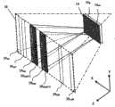
图2是图1A的可切换光学成像系统和3D/2D图像可切换装置的三维示意表示。该三维表示示出了垂直取向的平凸微透镜的柱镜光栅式透镜矩阵(lenticular matrice),以及在轴向和横向上的矩阵的相对位置。该三维表示还示出了视场中相邻的观察区。Fig. 2 is a three-dimensional schematic representation of the switchable optical imaging system and 3D/2D image switchable device of Fig. 1A. The three-dimensional representation shows a lenticular matrix of vertically oriented plano-convex microlenses, and the relative position of the matrix in the axial and transverse directions. The three-dimensional representation also shows adjacent viewing zones in the field of view.
图3A是从显示面的两个分别的分立区域发出并利用图1A的光学成像系统投影到视场内的代表性光束的三维图示,所述视场由它的横截面来图形地表示,其中,当光束的发散度相对小时,扫描操作模式中的视场被划分成以间隙彼此分开的多个可调节观察区。Figure 3A is a three-dimensional illustration of a representative light beam emanating from two respective discrete regions of the display surface and projected into a field of view, graphically represented by its cross-section, using the optical imaging system of Figure 1A, Wherein, when the divergence of the light beam is relatively small, the field of view in the scanning mode of operation is divided into a plurality of adjustable observation areas separated from each other by gaps.
图3B是从显示面的两个分别的区域发出并利用图1A的光学成像系统投影到视场中的代表性光束的三维图示,所述视场由它的横截面来图形地表示,其中,扫描操作模式中的视场被划分成多个可调节观察区,以便由于调节光束的发散度导致相邻观察区彼此邻接。3B is a three-dimensional illustration of a representative light beam emanating from two separate regions of the display surface and projected using the optical imaging system of FIG. 1A into a field of view graphically represented by its cross-section, wherein , the field of view in the scanning mode of operation is divided into a plurality of adjustable viewing areas such that adjacent viewing areas abut each other due to the adjustment of the divergence of the light beam.
图4A是根据本发明的第二优选实施例的图像可切换装置的扫描操作模式的一种修改中,在选择的时期内在图2中所示的矩阵复合体(complex)的水平往复移动(即沿X轴的移动)的时间矢量图。Fig. 4 A is according to a kind of modification of the scan mode of operation of the image switchable device of the second preferred embodiment of the present invention, in the horizontal reciprocating movement (i.e. The time vector diagram of the movement along the x-axis).
图4B是根据本发明的第二优选实施例的图像可切换装置的扫描操作模式的一种修改中,在选择的时期内在图2中所示的第一矩阵的轴向往复移动(即沿Z轴的移动)的时间矢量图,其中,该轴向往复移动与图4A中所示的水平往复移动同步。4B is a modification of the scanning mode of operation of the image switchable device according to the second preferred embodiment of the present invention, during a selected period of reciprocating movement in the axial direction of the first matrix shown in FIG. 2 (i.e. along Z axis movement) where the axial reciprocating movement is synchronized with the horizontal reciprocating movement shown in FIG. 4A.
图5A是根据本发明的扫描模式实施例的光学成像系统中的微透镜矩阵的一种光学布置的示意性表示,其中,第三矩阵位于第二矩阵的微透镜的后聚焦区域内,以及其中,第二矩阵与第一矩阵分开第一选择距离R1,使得F1<R1<2F1,以及使视场中相邻观察区彼此邻接。5A is a schematic representation of an optical arrangement of a matrix of microlenses in an optical imaging system according to a scanning mode embodiment of the present invention, wherein a third matrix is located within the back focus region of the microlenses of the second matrix, and wherein , the second matrix is separated from the first matrix by a first selected distance R1 such that F1 <R1 <2F1 , and such that adjacent observation zones in the field of view adjoin each other.
图5B是根据本发明的扫描模式实施例的光学成像系统中的微透镜矩阵的另一种光学布置的示意性表示,其中,第三矩阵位于第二矩阵的微透镜的后聚焦区域内,以及其中,第二矩阵与第一矩阵分开第一选择距离R1,使得(F1-F2)<R1<F1,以及使视场中相邻观察区彼此邻接。5B is a schematic representation of another optical arrangement of microlens matrices in an optical imaging system according to a scanning mode embodiment of the present invention, wherein a third matrix is located within the back focus region of the microlenses of the second matrix, and Wherein, the second matrix is separated from the first matrix by a first selected distance R1 such that (F1 −F2 )<R1 <F1 , and adjacent viewing areas in the field of view are adjacent to each other.
图5C是根据本发明的扫描模式实施例的光学成像系统中的微透镜矩阵的又一种光学布置的示意性表示,其中,第二矩阵位于第一矩阵的微透镜的后聚焦区域内,以及其中,第三矩阵与第二矩阵分开第二选择距离R2,使得R2<F2,以及使视场中相邻观察区彼此邻接。5C is a schematic representation of yet another optical arrangement of a microlens matrix in an optical imaging system according to a scanning mode embodiment of the present invention, wherein the second matrix is located within the back focus region of the microlenses of the first matrix, and Wherein, the third matrix is separated from the second matrix by a second selected distance R2 , such that R2 < F2 , and adjacent viewing areas in the field of view are adjacent to each other.
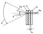
图6A是根据本发明的非扫描模式实施例的光学成像系统中的微透镜矩阵的一种光学布置的示意性表示,其中,第二矩阵与第一矩阵分开第一选择距离R1,以使0<R1<F1,以及使得由于调节变换后的光束的发散度,单个可调节观察区具有在视场(角大小ψ)中的选择角大小
图6B是根据本发明的非扫描模式实施例的光学成像系统中的微透镜矩阵的另一种光学布置的示意性表示,其中,第二矩阵与第一矩阵分开第一选择距离R1,以使F1<R1≤2F1,以及使得由于调节变换后的光束的发散度,单个可调节观察区具有在视场(角大小ψ)中的选择角大小
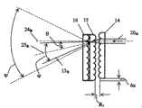
图7是根据本发明的非扫描模式实施例的光学成像系统中的微透镜矩阵的特定光学布置的示意性表示,其中,使矩阵复合件水平偏移(沿X轴)第三选择距离Δx,以使得由于调节变换后的光束的方向,单个可调节观察区具有在视场(角大小ψ)中的选择观察方向(角度θ)。7 is a schematic representation of a particular optical arrangement of a microlens matrix in an optical imaging system according to a non-scanning mode embodiment of the present invention, wherein the matrix composite is horizontally shifted (along the X axis) by a third selected distance Δx, Such that as a result of adjusting the direction of the transformed light beam, a single adjustable viewing zone has a selected viewing direction (angle Θ) in the field of view (angular size Ψ).
图8A是根据本发明的另一实施例的光学成像系统中平凸微透镜矩阵和显示面的一种特定光学布置的示意性表示,其中,第一矩阵的微透镜的平面面向显示面,而第二和第三矩阵的微透镜的平面背向显示面,以及其中,第一、第二和第三矩阵包括各自的第一、第二和第三基板。8A is a schematic representation of a specific optical arrangement of a plano-convex microlens matrix and a display surface in an optical imaging system according to another embodiment of the present invention, wherein the plane of the microlenses of the first matrix faces the display surface, and The planes of the microlenses of the second and third matrices face away from the display surface, and wherein the first, second and third matrices include respective first, second and third substrates.
图8B是根据本发明的又一实施例的光学成像系统中平凸微透镜矩阵和显示面的另一种特定光学布置的示意性表示,其中,第一和第三矩阵的微透镜的平面面向显示面,而第二矩阵的微透镜的平面背向显示面,以及其中,第一矩阵包括第一基板,而第二和第三矩阵包括共享的共用基板。8B is a schematic representation of another specific optical arrangement of a plano-convex microlens matrix and a display surface in an optical imaging system according to yet another embodiment of the present invention, wherein the planes of the microlenses of the first and third matrices face The display surface, while the plane of the microlenses of the second matrix faces away from the display surface, and wherein the first matrix includes a first substrate, and the second and third matrices include a shared common substrate.
图9是根据本发明的另一实施例的图像可切换装置的单色操作模式下的显示组件的一种变形的示意性表示,其中,该显示组件包括空间光调制器-微型显示器、光引擎和投影光学系统,该示意性表示还示出了第一平凸微透镜矩阵。9 is a schematic representation of a variant of a display assembly in a monochrome mode of operation of an image switchable device according to another embodiment of the present invention, wherein the display assembly includes a spatial light modulator-microdisplay, a light engine and projection optics, the schematic representation also shows a first matrix of plano-convex microlenses.
图10A是根据本发明的另一实施例的图像可切换装置的单色操作模式下的显示组件的另一变形的示意性表示,其中,该显示组件包括空间光调制器-微型显示器、光引擎、投影光学系统和垂直散射光学组件,以及其中,该垂直散射光学组件是水平取向的圆柱状平凸微透镜的柱镜光栅式透镜矩阵。该示意性表示还示出光学矩阵组件,所述光学矩阵组件包括垂直取向的圆柱状平凸微透镜的第一、第二和第三柱镜光栅式透镜矩阵。10A is a schematic representation of another variant of a display assembly in a monochrome mode of operation of an image switchable device according to another embodiment of the invention, wherein the display assembly includes a spatial light modulator-microdisplay, a light engine , a projection optical system and a vertical scattering optical component, and wherein the vertical scattering optical component is a lenticular lens matrix of horizontally oriented cylindrical plano-convex microlenses. The schematic representation also shows an optical matrix assembly comprising first, second and third lenticular lens matrices of vertically oriented cylindrical plano-convex microlenses.
图10B是图10A中所示的显示组件的变形的俯视图。Figure 10B is a top view of a variation of the display assembly shown in Figure 10A.
图11是根据本发明的另一实施例的图像可切换装置的多色操作模式下的显示组件的结构的示意性表示,其中,该显示组件包括:第一、第二和第三空间光调制器-微型显示器;分别配置用于辐射第一、第二和第三选择色的光的第一、第二和第三光引擎;用来空间叠加第一、第二和第三选择色的叠加光学系统;投影光学系统;以及垂直散射光学组件,其中,该垂直散射光学组件是水平取向的圆柱状平凸微透镜的柱镜光栅式透镜矩阵。该示意性表示还示出垂直取向的圆柱状平凸微透镜的第一、第二和第三柱镜光栅式透镜矩阵。11 is a schematic representation of the structure of a display assembly in a multi-color operation mode of an image switchable device according to another embodiment of the present invention, wherein the display assembly includes: first, second and third spatial light modulation device-microdisplay; first, second, and third light engines respectively configured to radiate light of first, second, and third selected colors; superposition for spatially superimposing first, second, and third selected colors an optical system; a projection optical system; and a vertical scattering optical component, wherein the vertical scattering optical component is a lenticular lens matrix of horizontally oriented cylindrical plano-convex microlenses. The schematic representation also shows first, second and third lenticular lens matrices of vertically oriented cylindrical plano-convex microlenses.
图12是根据本发明的另一实施例的图像可切换装置的单色操作模式中的显示组件的另一变形的示意性表示,其中,该显示组件包括空间光调制器(SLM)和投影光学系统,其中,该投影光学系统是用于图像传输的光纤系统,以及其中SLM的成像表面的每个区域通过光纤系统的各个光纤光学地耦合到显示面的各个区域。该示意性表示还示出平凸微透镜的第一矩阵包括第一基板。Figure 12 is a schematic representation of another variant of the display assembly comprising a spatial light modulator (SLM) and projection optics in a monochrome mode of operation of an image switchable device according to another embodiment of the invention. A system wherein the projection optics is a fiber optic system for image transmission, and wherein each region of the imaging surface of the SLM is optically coupled to a respective region of the display surface via a respective fiber of the fiber optic system. The schematic representation also shows that the first matrix of plano-convex microlenses comprises a first substrate.
具体实施方式Detailed ways
本发明旨在提供在许多方面具有高功能灵活性和对于多种不同应用的适应性的可切换光学成像系统和相关3D/2D图像可切换装置(3D/2D显示器)的数种变形。因此,根据某些优选实施例,描述和示例说明在此公开的本发明的光学成像系统和相关装置,优选实施例包括能够根据具体应用在多种不同操作模式中操作的多种不同结构和光学布置。在多种不同操作模式中,有扫描和非扫描操作模式的几种改进。本发明的功能灵活性和适应性包括诸如如下的方面:切换操作模式或结合使用一些操作模式的能力、改变工作参数和调节每个操作模式中的操作特性的能力、图像缩放和调节图像亮度的能力等等。因此以及根据本发明,能够容易地调节操作特性,诸如视场中的观察区的角大小、方向和数量,视场的角大小和深度,以及3D图像的角图像分辨率、深度以及选择2D图像的动态范围。The present invention aims to provide several variants of switchable optical imaging systems and related 3D/2D image switchable devices (3D/2D displays) with high functional flexibility in many respects and adaptability to many different applications. Thus, the inventive optical imaging systems and associated apparatus disclosed herein are described and illustrated according to certain preferred embodiments, which include a variety of different structures and optics capable of operating in a number of different modes of operation depending on the particular application. layout. Among the various modes of operation, there are several improvements for scanning and non-scanning modes of operation. The functional flexibility and adaptability of the present invention includes aspects such as the ability to switch modes of operation or use some in combination, the ability to change operating parameters and adjust operating characteristics in each mode of operation, the ability to zoom and adjust image brightness ability and so on. Thus and in accordance with the present invention, operational characteristics such as angular size, direction and number of observation zones in the field of view, angular size and depth of the field of view, and angular image resolution, depth for 3D images and selection of 2D images can be easily adjusted. dynamic range.
现在参考附图,其中,相同的参考数字表示相同或相应的元件,以及更具体地参考图1A-B,根据各个第一和第二优选实施例的本发明包括可切换光学成像系统1和相关3D/2D图像可切换装置2。3D/2D图像可切换装置2(结合光学成像系统1)意图用来分别在3D和2D操作模式下在视场中形成物体或场景的3维(3D)图像的多个透视图和/或2维(2D)图像。如图1A中最佳所示,本发明3D/2D图像可切换装置2包括显示组件3、光学成像系统1(其中,光学成像系统1进一步包括光学矩阵组件4和包括至少第一和第二驱动器5、6的位移机构(为简化起见,在图1A中未指出)、包括至少第一和第二位置传感器7、8的传感器系统(为简化起见,在图1A中未指出)以及控制器9。显示组件3用来生成2维图案以及具有显示2维图案的显示面10。显示组件3还具有用于更新2维图案的数字数据输入11和同步(控制)输入12。Referring now to the drawings, wherein like reference numerals designate like or corresponding elements, and more particularly to FIGS. 1A-B , the invention according to respective first and second preferred embodiments comprises a switchable
可切换光学成像系统1变换从显示组件3的显示面10发出的光束20并将变换后的光束13投影到视场中,由此将视场划分成一个或多个可调节观察区(在图2中示出了一些观察区)。这些功能由光学矩阵组件4来实现。如图1A中最佳所示,光学矩阵组件4包括:会聚微透镜的第一矩阵14;光学耦合到第一矩阵14的微透镜的会聚微透镜的第二矩阵15;以及同轴对齐到并刚性地连结到第二矩阵15的微透镜的会聚微透镜的第三矩阵16,使第二矩阵15和第三矩阵16结合定义矩阵复合件(其中,为简化起见,该矩阵复合件自身在图1A中未示出)。在图1A-1B中将第一矩阵14、第二矩阵15和第三矩阵16分别示为平凸微透镜的第一矩阵14、第二矩阵15和第三矩阵16。The switchable
第一矩阵14和矩阵15、16的复合件分别安装在位移机构的第一和第二驱动器5,6上。如图1A中所示,第一驱动器5被配置用来相对于矩阵15、16的复合件轴向移动第一矩阵14(即沿Z轴)。类似地,第二驱动器6被配置用来相对于第一矩阵14水平地移动矩阵15、16的复合件(即沿X轴)。图1B进一步示出在图像可切换装置2中光学矩阵组件4的矩阵14、15、16与显示组件3的显示面10的相对位置。The
更具体地说,图1B示出第一矩阵14的典型平凸微透镜17ik,具有面向显示面10的平面18ik并通过发出光束20ik沿相应光轴19ik光学地耦合到显示面10的一相应区域10ik。而第二矩阵15和第三矩阵16各自的微透镜21ik和22ik的平面背向显示面10(为简化起见,仅在图1B中示出了微透镜22ik的平面23ik)。如所示,第二矩阵15和第三矩阵16各自的微透镜21ik、22ik光学地耦合、同轴对齐并共享与第一矩阵14的微透镜17ik的光轴19ik平行的共用光轴24ik。如进一步所示,第一矩阵14和第二矩阵15各自的微透镜17ik、21ik光学地耦合并彼此间隔开第一选择距离R1。第二矩阵15和第三矩阵16各自的微透镜21ik、22ik彼此间隔开第二选择(预定)距离R2。因此,在该光学布置中,图1B示出从显示面10的一个相应区域10ik发出典型光束20ik并由光学成像系统1的第一矩阵14、第二矩阵15和第三矩阵16各自的平凸微透镜17ik、21ik、22ik变换成沿轴25ik投影到视场中的偏转并变换后的光束13ik的路线。More specifically, FIG. 1B shows a typical plano-convex microlens17ik of the
根据上文和再参考图1A,重要的是要注意,光学成像系统1和图像可切换装置2的功能灵活性和适应性基于提供在轴向和横向上的矩阵或多矩阵移动。结合在此公开的几种方案,优选地同样地(equally)应用这种移动。例如,在图1A所示的优选方案中(以及涉及本发明的第一和第二优选实施例),位移机构(未示出)的第一驱动器5和第二驱动器6分别被配置用来相对于矩阵15、16的复合件轴向移动第一矩阵14以及相对于第一矩阵14水平移动矩阵15、16的复合件。能够根据选择操作模式以多种方式执行矩阵或多矩阵移动。In light of the above and with reference again to FIG. 1A , it is important to note that the functional flexibility and adaptability of the
在与本发明的扫描模式实施例有关的扫描操作模式中,第二驱动器6进一步被配置用来以往复方式执行矩阵15、16的复合件的水平移动。该扫描操作模式使得能够将视场划分成多个可调节观察区,使得能够与视场中的变换后的光束13相一致地扫描这些观察区。如果第一驱动器5还被配置为在该操作模式中执行第一矩阵14的轴向移动以调节变换后的光束13的发散度,那么该扫描操作模式进一步使得在视场中相邻观察区邻接。多个观察区意图用来在其中投影:(i)在3D操作模式中的特定3D图像的相应透视图,或(ii)2D扫描操作模式中的相同2D图像。当“相邻观察区邻接”,或换句话说,“提供相邻观察区的邻接”时(在此这些术语类似和同样地使用),当从一个观察区移到另一个时,观察者不会在视觉上感知图像亮度的变化。在下文中,将参考图2、3A-3B更详细地描述相邻观察区的邻接。In the scanning mode of operation in relation to the scanning mode embodiment of the invention, the second drive 6 is further configured to perform a horizontal movement of the composite of
在与本发明的非扫描模式实施例有关的非扫描操作模式中,单个可调节观察(观测)区用来在其中投影特别感兴趣的2D图像。在该操作模式中,第二驱动器6进一步配置用来执行将矩阵15、16的复合件水平移动(沿X轴)第三选择(预定)距离Δx,而第一驱动器5进一步配置用来执行第一矩阵14的轴向移动(沿Z轴)以调节变换后的光束13的发散度。为了提供例如观察2D图像的所需等级的机密度(confidentiality)的目的,允许视场中单个可调节观察区具有选择观察方向和选择角大小。在下文中,将参考图6A-B、7更详细地讨论非扫描操作模式。In the non-scanning mode of operation associated with the non-scanning mode embodiment of the present invention, a single adjustable viewing (observation) zone is used to project therein a 2D image of particular interest. In this mode of operation, the second drive 6 is further configured to perform a horizontal movement (along the X-axis) of the composite of
通过改变第一矩阵14和矩阵15、16的复合件沿Z轴的相对位置,手动地切换操作模式(如在根据本发明的第一优选实施例的光学成像系统1中)。在下文中,将参考图6A-B更详细地讨论。然而,优选在控制器9的帮助下切换操作模式。为了切换操作模式或结合使用操作模式,控制矩阵或多个矩阵移动的工作参数以及调节每个操作模式中的操作特性,图像可切换装置中的第一驱动器5和第二驱动器6具有各自的控制输入26和27,该控制输入26和27分别是位移机构的第一和第二控制输入。通过意图用于确定(检测)第一矩阵14和矩阵15、16的复合件分别在轴向和水平方向上的相对位置的传感器系统的第一和第二位置传感器7、8,执行矩阵或多个矩阵移动的工作参数控制。第一和第二位置传感器7、8具有各自的数据输出28和29,该数据输出28和29分别是传感器系统的第一和第二数据输出。The mode of operation is switched manually (as in the
控制器9通常被用于切换操作模式、控制每一操作模式中的矩阵或多个矩阵移动的工作参数以及用于使得利用显示组件生成2维图案与矩阵或多个矩阵移动同步。控制器9具有:至少第一和第二数据输入30、31;同步输出33;和至少第一和第二控制输出34、35。控制器9的第一和第二数据输入30、31分别被连接到传感器系统中的第一和第二位置传感器7、8各自的数据输出28、29。控制器9的同步输出33连接到显示组件3的同步(控制)输入12。另外,控制器9的第一和第二控制输出34、35分别被连接到位移机构中的驱动器5、6各自的控制输入26、27。The controller 9 is typically used to switch the modes of operation, to control the working parameters of the movement of the matrix or matrices in each mode of operation, and to synchronize the generation of 2-dimensional patterns with the display assembly with movement of the matrix or matrices. The controller 9 has: at least first and
计算机36是3D/2D图像可切换装置2的辅助组件(根据本发明的第二优选实施例),为此,图1A中将它示为在用被虚线环绕的框内。计算机36能用作主控制器,用于选择或改变操作模式或通过生成各个命令信号并传送到控制器9来形成新的操作模式,以及用于通过将与新的2维图案有关的数据传送到显示组件3来更新2维图案。为执行这些功能,计算机36具有控制命令输出(在图1A中未示出)和连接到显示组件3的数据输入11的数据输出(在图1A中未示出),而控制器9进一步具有连接到计算机36的控制命令输出的控制命令输入32。The
根据上文和再次参考图1A,可切换光学成像系统1(根据本发明的第一优选实施例)意图用来变换从显示2维图案的显示面10发出的光束20并用来在视场中投影变换后的光束13,由此将视场划分成一个或多个可调节观察区(如在图2、3A-B、6A-B和7中所示)。According to the above and referring again to FIG. 1A , a switchable optical imaging system 1 (according to a first preferred embodiment of the invention) is intended to transform a
如图1A-B中最佳所示,光学成像系统1包括:会聚微透镜17的第一矩阵14,其中每个微透镜17ik沿各自光轴19ik光学地耦合到显示面10的一个相应区域10ik;会聚微透镜21的第二矩阵15,所述会聚微透镜21光学地耦合到第一矩阵14的微透镜17;会聚微透镜22的第三矩阵16,所述会聚微透镜22同轴对齐并刚性地连结到第二矩阵15的微透镜21,使第二矩阵15和第三矩阵15结合定义矩阵复合件;以及位移机构(未示出),用于相对于彼此轴向地移动第一矩阵14或矩阵15、16的复合件,以及用于相对于彼此横向地移动第一矩阵14或矩阵15、16的复合件。As best shown in FIGS. 1A-B , the
另外,如在前所述和图1A中最佳所示,使用可切换光学成像系统1的3D/2D图像可切换装置2意图用来分别在3D和2D操作模式中形成视场中的物体或场景的3维图像的多个透视图和/或2维图像。图像可切换装置2包括:显示组件3,用于生成2维图案,该显示组件3具有用于更新2维图案的数据输入11、同步输入12和用于显示2维图案的显示面10;可切换光学成像系统1,用于变换从显示面10发出的光束20,以及用于在视场中投影变换后的光束13,由此将视场划分成一个或多个可调节观察区(如图2、3A-B、6A-B和7中所示),包括:会聚微透镜17的第一矩阵14,其中每个微透镜17ik沿各自光轴19ik光学地耦合到显示面10的一个相应区域10ik;会聚微透镜21的第二矩阵15,所述会聚微透镜21光学地耦合到第一矩阵14的微透镜17;会聚微透镜22的第三矩阵16,所述会聚微透镜22同轴对齐并刚性地连结(连结或连接)到第二矩阵16的微透镜21,使第二矩阵15和第三矩阵16结合定义矩阵复合件;以及位移机构(未示出),用于相对于彼此轴向地移动第一矩阵14或矩阵15、16的复合件,以及用于相对于彼此横向地移动第一矩阵14或矩阵15、16的复合件,该位移机构具有至少第一和第二控制输入26、27;传感器系统,用于检测第一矩阵14和矩阵15、16的复合件在轴向和横向上的相对位置,该传感器系统具有至少第一和第二数据输出28、29;以及控制器9,用于切换操作模式,控制在每个操作模式中的矩阵或多个矩阵移动的工作参数,以及用于使得利用显示组件3生成2维图案与矩阵或多个矩阵移动同步,该控制器具有(i)至少第一和第二数据输入30、31,控制器9的第一和第二数据输入30、31分别连接到传感器系统的第一和第二数据输出28、29,(ii)同步输出33,连接到显示组件3的同步输入12;以及(iii)至少第一和第二控制输出34、35,控制器9的第一和第二控制输出34、35分别连接到位移机构的第一和第二控制输入26、27。In addition, as previously described and best shown in FIG. 1A , the 3D/2D image
如前所提到的,能够利用与在图1A中所示的优选方案不同的方式来能提供轴向和横向(例如水平)方向上的矩阵或多个矩阵移动。因此,在一个替代方案中,第一矩阵14安装在组合驱动器(图1A中未示出)上,该组合驱动器是位移机构(未示出)的第一和第二驱动器5、6的组合,由此形成如在现有技术中已知的双轴(X/Z)驱动器。在一个替代方案中,第一和第二驱动器5、6分别配置用来相对于矩阵15、16的复合件轴向(沿Z轴)和水平(沿X轴)移动第一矩阵14。在一个或多个替代方案中,矩阵15、16的复合件安装在组合驱动器上,该组合驱动器是位移机构的第一和第二驱动器5、6的组合并形成双轴(X/Z)驱动器。在一个或多个替代方案中,第一和第二驱动器5、6分别配置用来相对于第一矩阵轴向(沿Z轴)和水平(沿X轴)移动矩阵15、16的复合件。在另一替代方案中,矩阵15、16的复合件和第一矩阵14分别安装在位移机构的第一和第二驱动器5、6上。第一和第二驱动器5、6分别配置用来相对于第一矩阵14轴向(沿Z轴)地移动矩阵15、16的复合件以及相对于矩阵15、16的复合件水平(沿X轴)地移动第一矩阵14。As previously mentioned, matrix or matrix movement in axial and transverse (eg horizontal) directions can be provided in different ways than the preferred solution shown in Figure 1A. Thus, in an alternative, the
在有关光学成像系统1和图像可切换装置2的所有替代方案中(根据本发明的各个替代实施例),能够以往复方式执行相对于彼此的水平方向中的矩阵或多个矩阵移动。与有关优选方案的扫描操作模式相同,这种往复移动使得能够将视场划分成多个可调节观察区以及使得能够在视场中与变换后的光束13一致地扫描这些观察区。此外,在所有替代方案中,与在图1A中所示的优选方案类似,相对于彼此的轴向中的矩阵或多个矩阵移动通过调节变换后的光束13的发散度,使得视场中的相邻观察区邻接。In all alternatives concerning the
因此,当比较替代和优选方案中执行的矩阵或矩阵移动时,对本领域的技术人员而言,改变第一矩阵14和矩阵15、16的复合件在轴向和横向方向中相对于彼此的相对位置的重要性是显而易见的(而不是它们中的哪一个,第一矩阵14或矩阵15、16的复合件,被实际移动)。在描述位移机构的一般功能时反映了这种情形,位移机构的一般功能意图用于相对于彼此轴向移动第一矩阵14或矩阵15、16的复合件以及用于相对于彼此横向移动第一矩阵14或矩阵15、16的复合件。为此,根据优选方案的说明,能理解到根据本发明的替代实施例的替代方案的重要性。换句话说,与本发明的第一和第二优选实施例有关的优选方案是用于解释它们的本质和特性的替代实施例的典型方案。后者还表示替代实施例的典型还是与优选方案有关的扫描和非扫描操作模式的解释,特别是参考图2、3A-B在下文中所述的相邻观察区的邻接的解释。Therefore, when comparing the matrices or matrix shifts performed in the alternative and preferred solutions, it is a matter for a person skilled in the art to vary the relative orientation of the
应注意到在许多方面中光学成像系统1和图像可切换装置2的功能灵活性和适应性是基于调节变换后的光束13的发散度(见图1A)。因此,在3D和2D扫描操作模式中,都允许提供视场中相邻观察区的邻接,由此在这些模式中实现本发明的主要思想。在此参考图2对该方面进行讨论,其示出了光学成像系统1的具体结构的三维示意性图示。在图2中,通过垂直取向(沿Y轴)的平凸微透镜的第一、第二和第三柱镜光栅式透镜矩阵14、15、16,表示该光学矩阵组件4。以及由此,当第二驱动器6以往复方式相对于第一矩阵14执行矩阵15、16的复合件的水平移动(沿X轴)时,在水平(XZ)平面中设置多个可调节观察区。例如,在图2中示出了在X方向中布置的相邻观察区37(i+1)k(虚线)、37ik(实线)和37(i-1)k(虚线)。在第一驱动器5的帮助下,通过相对于矩阵15、16的复合件轴向移动第一矩阵14(沿Z轴),能调节典型观察区37ik的角大小。具有偏差量Δz的第一矩阵14的位置对应于相邻观察区37的邻接并指定典型观察区37ik的角大小

当提供相邻观察区37的邻接时,如图2中所示,通过表达式

另外,应注意到,由于光学矩阵组件4的该特定结构,该3D图像仅具有水平视差。当在光学成像系统1中使用球面微透镜的矩阵14、15、16来代替图2中所示的柱镜光栅式透镜矩阵14、15、16时,观察者能在视觉上感知观察为具有全视差的3D图像。对该光学矩阵组件4的该特定结构,恰如上参考图1A所述,在第一驱动器5的帮助下,通过相对于球面微透镜矩阵15、16的复合件轴向移动球面微透镜的第一矩阵14(沿Z轴),能在两个横向中(即沿X轴和Y轴)提供相邻观察区的邻接。用于光学矩阵组件4的该特定结构的扫描过程要求位移机构具有第三驱动器(图1中未示出),所述第三驱动器被配置用来(i)相对于球面微透镜矩阵15、16的复合件,垂直地移动球面微透镜的第一矩阵14;或(ii)相对于球面微透镜的第一矩阵14,垂直地移动球面微透镜矩阵15、16的复合件。与上述第一和第二驱动器5、6相同,第三驱动器具有控制输入,该控制输入是位移机构的第三控制输入。能够使用本领域已知的任何方式在水平和垂直方向中布置视场中的观察区的扫描过程。在该过程中,第二驱动器6以往复方式执行矩阵15、16的复合件的水平移动以便提供水平扫描,而第三驱动器执行第一矩阵14的垂直移动以便提供垂直扫描。控制器9具有连接到位移机构的第三控制输入的第三控制输出,并被配置用来控制第三驱动器动作和另外使例如第一矩阵14的垂直移动与矩阵15、16的复合件的水平往复移动同步。In addition, it should be noted that due to this specific structure of the
将参考图3A-B,进一步描述在相邻观察区的邻接方面中的本发明的扫描模式实施例的特性。它们中的每一个是从显示面10的两个分别区域10ik和10im发出并由图1A的光学成像系统1投影到视场中的典型光束(未示出)的三维图示。视场利用与显示面10相距特定距离处的它的矩形截面图38(虚线)来图形表示,并且它在水平(XZ)面中的角大小为ψ。在扫描操作模式中(例如在3D操作模式中),将视场划分成多个可调节观察区以在其中投影3D图像的透视图。所述典型的光束在XZ面中具有小的水平发散度(未示出)和角度ξ的增大的垂直发散度(沿Y轴),用于扩大视场的垂直大小,在下文中将参考图10A-B描述。由此,如在图3A-B中所示,对各种透视图,来自区域10ik和10im的所述典型光束在横截面38上的投影(例如39ikq,39imq)在垂直方向上是细长的。对这些投影39ikq,39imq,各个区域的位置用显示面10上的行序数i(i=1…n)和列序数k(k=1…m)来指定,其中,q是特定透视图的序数(q=1…N)。因此,当XZ面中的光束的发散度相对小时,观察者能看出由图3A中所示的投影39ikq与39ikq+1或39imq与39imq+1间的间隙表示的、相邻透视图(相应的可调节观察区37)间的间隙。通过如上参考图1A所述适当地调节光束13的发散度,如在图3B中所示对同样的光束投影39ikq与39ikq+1或39imq与39imq+1提供相邻透视图(相应可调节观察区37)的所述邻接。The characteristics of the scan mode embodiments of the present invention in terms of the contiguousness of adjacent viewing zones will be further described with reference to FIGS. 3A-B . Each of them is a three-dimensional representation of a typical light beam (not shown) emanating from two respective regions10ik and10im of the
在根据本发明的扫描模式实施例的2D扫描操作模式中,在每个观察区37中投影相同的2D图像。当提供相邻观察区37的邻接时,如在3D操作模式中那样,当从一个观察区移动到另一个观察区时,观察者能看到特定2D图像而在视觉上感知不到图像亮度的改变,以及在2D模式中重要的,在视觉上感知不到任何透视失真。此外,投影的2D图像的分辨率具有与在特定3D图像的透视图中相同的水平,并本质上受所使用的显示组件3的分辨率限制。In the 2D scanning mode of operation according to the scanning mode embodiment of the present invention, the same 2D image is projected in each
应进一步注意到,在一些方面中的光学成像系统1和图像可切换装置2的功能灵活性和适应性基于改变可调节观察区37的数量。物体或场景的深度越大,则在视场中使用的可调节观察区37(或3D操作模式中的透视图)的数量应当更多以便再现它的空间特性。另一方面,当增加可调节观察区37的数量并在视场的特定角大小ψ中保持相邻观察区邻接时,减小每个观察区37的角大小
因此,在一些应用中(例如在医疗应用中),形成具有高角分辨率的3D图像很重要。在诸如广告的应用中,优选高图像亮度和宽视场。在要对不止一个人同时提供相同视觉信息的那些应用中,宽和/或深的视场是必要的。在这些应用中,应当使用大量的透视图。Therefore, in some applications, such as in medical applications, it is important to form 3D images with high angular resolution. In applications such as advertising, high image brightness and wide field of view are preferred. In those applications where the same visual information is to be provided to more than one person simultaneously, a wide and/or deep field of view is necessary. In these applications, a large number of perspective views should be used.
此外,根据本发明的第二优选实施例,可调节观察区37(或3D操作模式中的透视图)的数量最终受将用在图像可切换装置2中的显示组件3的帧频R限制。帧频R应当满足要求R>Nf,其中,f是眼睛的临界频率(通常约或大于30Hz)。因此,帧频R越高(意味着显示组件3的更高吞吐量),能使用更多透视图以形成具有更高质量的3D图像。另一方面,用在3D操作模式中的显示组件3的吞吐量越高,通过增加透视图的数量能获得视场的更大角大小和深度。Furthermore, according to the second preferred embodiment of the invention, the number of adjustable viewing zones 37 (or perspective views in 3D mode of operation) is ultimately limited by the frame rate R of the
在与上述图像可切换装置2(根据本发明的第二优选实施例或替代实施例)的任何方案(优选或替代)有关的扫描操作模式中,利用显示组件3生成2维图案应当与矩阵或多个矩阵移动同步,或者换句话说应当与扫描多个观察区37的过程同步,以便在各个观察区37中投影3D操作模式中的特定3D图像的每个透视图或2D扫描操作模式中的相同2D图像。在所述方案的每一个中,利用控制器9(见图1A)执行该同步。例如,在优选方案中,控制器9使在显示组件3的显示面10上显示2维图案的时刻与矩阵15、16的复合件相对于第一矩阵14在水平方向(沿X轴)上的相应位置同步。控制器9使用来自第一和第二位置传感器7、8的数据输出28、29的信号进行所述同步。控制器9还用于切换操作模式。In the scanning mode of operation associated with any of the schemes (preferred or alternative) of the image
将图像可切换装置2的功能灵活性和适应性的一个或多个方面(根据本发明的扫描模式实施例)与结合使用操作模式来满足一些特定应用中的需求相关联。因此,在与图像可切换装置2(如图1A所示)的优选方案有关的扫描操作模式的一种改进中,第二驱动器6进一步配置用来相对于第一选择位置(例如位置X=0)执行第二矩阵15、16的复合件的水平(沿X轴)往复移动,此处第二矩阵15的微透镜与第一矩阵14的微透镜同轴对齐。而第一驱动器5进一步配置用来以往复方式相对于第二选择(预定)位置Z0执行第一矩阵14的轴向移动(沿Z轴),此处在视场中相邻观察区37是邻接的。控制器9被配置用来控制第一和第二驱动器5、6的动作以及另外使得第一矩阵14的轴向往复移动与矩阵15、16的复合件的水平往复移动同步,如图4A-B中所示。One or more aspects of the functional flexibility and adaptability of the image switchable device 2 (according to the scanning mode embodiment of the present invention) are associated with using the operating modes in conjunction with meeting the needs in some specific applications. Therefore, in a refinement of the scanning mode of operation associated with the preferred version of the image switchable device 2 (as shown in FIG. 1A ), the second drive 6 is further configured to ) performs a horizontal (along the X-axis) reciprocating movement of the composite of the
因此在选择时间周期上在图4A中示出了矩阵15、16的复合件的水平移动的时序图。振幅Ax和周期Tx是该水平移动的工作参数。控制器9被配置用来调节峰-峰振幅Ax,以便它优选受相应矩阵(在该方案中受第二矩阵15)的微透镜的孔径限制。实际上,该限制也能应用于任何替代方案。在相同的选择时间周期上,在图4B中示出了具有周期Tz=Tx/2和振幅Az作为工作参数的第一矩阵14的轴向移动的时序图。进一步利用控制器9调节轴向移动的振幅Az,以便该振幅Az由第二矩阵15的微透镜的曲率半径来确定。A timing diagram of the horizontal movement of the composite of
相对于上述方案该改进允许提高在可调节观察区37中所投影的透视图或相同2D图像的质量。这通过在第一矩阵14与矩阵15、16的复合件相对于彼此的水平往复移动期间减小它们之间的光路的变化来说明。This improvement with respect to the solution described above allows to increase the quality of the perspective view or the same 2D image projected in the
在与图像可切换装置2的另一替代方案有关的扫描操作模式的其他改进中,能获得相同的结果。在该改进中,第二驱动器6被配置用来相对于第一选择位置执行第一矩阵14的水平往复移动,而第一驱动器5则配置用来相对于第二选择位置Z0执行矩阵15、16的复合件的轴向往复移动。The same result can be obtained in other refinements of the scanning mode of operation in relation to another alternative of the image
在一些特定应用中,同时观看3D图像和2D图像很重要。在与图像可切换装置2的优选或替代方案有关的扫描操作模式中,通过同时地执行3D操作模式和2D扫描操作模式是可能的。在本发明的该特定扫描模式实施例中,第二驱动器6被配置用来以往复方式执行矩阵或多个矩阵水平移动,以便在视场中与变换后的光束13一致地扫描多个可调节观察区37。而控制器9配置用来控制第二驱动器6动作和使得利用显示组件3生成2维图案的序列与矩阵或多个矩阵水平移动同步,以便要在一个观察区37中投影的每个2维图案包含相应透视图和选择2D图像的叠加。结合使用3D和2D扫描操作模式的特性是3D图像和选择2D图像具有相同高图像分辨率的事实。In some specific applications, it is important to view 3D images and 2D images simultaneously. In the scanning mode of operation related to the preferred or alternative of the image
在与上述的光学成像系统1和图像可切换装置2的优选或替代方案有关的扫描操作模式(或其改进)中,使第一矩阵14或矩阵15、16的复合件相对于彼此在轴向(沿Z轴)上移动选择距离并保持在选择位置上(或相对于该选择位置执行轴向往复移动),提供视场中的相邻观察区的邻接。能够在成为光学成像系统1和图像可切换装置2的功能灵活性和适应性的另一方面的微透镜的矩阵14、15、16的各种光学布置中实现该结果。在图5A、B、C中示出了根据本发明的扫描模式实施例的矩阵14、15、16的一些光学布置的示意性图示,其中,第一矩阵14的微透镜具有第一焦距F1,以及第二矩阵15的微透镜具有第二焦距F2。In the scanning mode of operation (or a modification thereof) associated with the above-described preferred or alternative solutions of the
因此,在如图5A所示的一种光学布置中,第二矩阵15与第一矩阵间隔开第一选择距离R1,以致F1<R1<2F1,以及第三矩阵16与第二矩阵15间隔开第二距离R2,并位于第二矩阵15的微透镜的后聚焦区域内。在如图5B所示的另一光学布置中,第二矩阵15与第一矩阵14间隔开第一选择距离R1,以致(F1_F2)<R1<F1,以及第三矩阵16与第二矩阵15间隔开第二选择距离R2并位于第二矩阵15的微透镜的后聚焦区域中。Thus, in an optical arrangement as shown in FIG. 5A, the
而在图5C中所示的另一光学布置中,第二矩阵15与第一矩阵14间隔开第一选择距离R1,并位于第一矩阵14的微透镜的后聚焦区域中,以及第三矩阵16与第二矩阵15间隔开第二选择距离R2,以致R2<F2。In another optical arrangement shown in FIG. 5C , the
如果在相应的光学布置中,第二矩阵15在第一矩阵14的微透镜的焦平面外(但在后聚焦区域内),光学成像系统1和图像可切换装置2的操作特性不会显著地改变。另一方面,使得能够消减或基本上减小光学成像系统1和图像可切换装置2对于矩阵或多个矩阵移动的不准确的灵敏度。此外,能通过使用具有不同焦距的微透镜的第一、第二和第三矩阵14、15、16,实现灵敏度的降低。通过使用具有平坦基板的矩阵,也能实现类似的结果。因此,平凸微透镜的第一矩阵14、第二矩阵15和第三矩阵16可以具有各自的第一、第二和第三基板,每一基板是具有与相应矩阵的微透镜的平面的光学接触的平的透明板(更详细地参考图8A)。If, in the corresponding optical arrangement, the
在非扫描操作模式中,光学成像系统1意图用来选择视场中的单个可调节观察区的观察方向和角大小,并意图用于在其中投影感兴趣的2D图像。与上述详细所述的扫描操作模式类似,这种选择能在微透镜的矩阵的一些光学布置中实现。例如,图6A-B、7示意性地表示根据本发明的非扫描模式实施例的光学成像系统1和图像可切换装置2中的会聚微透镜的矩阵的一些光学布置。如所示,第一矩阵14或矩阵15、16的复合件相对于彼此在轴向上(沿Z轴)移动,用于调节变换后的光束13的发散度,以便单个可调节观察区具有视场(角大小ψ)中的选择角度大小

在图6A-B的光学布置中,第一矩阵14的微透镜具有第一焦距F1,以及第二矩阵15的微透镜具有第二焦距F2。矩阵15、16的复合件被保持在水平方向上相对于第一矩阵14的选择位置处,例如,保持在第二矩阵15的微透镜与第一矩阵14的微透镜共轴对齐(X=0)的位置上。In the optical arrangement of Figures 6A-B, the microlenses of the
另外,在图6A所示的一个光学布置中,第二矩阵15与第一矩阵14间隔开第一选择距离R1,以便0<R1<F1。Additionally, in one optical arrangement shown in Figure 6A, the
在图6B所示的另一光学布置中,第二矩阵15与第一矩阵14间隔开第一选择距离R1,以便F1<R1≤2F1。In another optical arrangement shown in FIG. 6B , the
如图6A-B、7中对于非扫描操作模式所示,示出了典型光束20ik利用矩阵14、15、16变换成光束13ik,该光束13ik如图6A-B所示沿它们的微透镜的共用光轴(未示出),或沿与矩阵15、16的复合件的微透镜的共用光轴24ik成角度θ的偏转光轴25ik,投影到视场中。As shown in Figs. 6A-B, 7 for the non-scanning mode of operation, typical beams20ik are shown transformed into beams13ik using matrices 14, 15,16 along their A common optical axis (not shown) of the microlenses, or a deflected optical axis 25ik at an angle θ to the common
如在根据本发明的第一优选实施例的光学成像系统1中在手动控制的第一驱动器5和第二驱动器6的帮助下,或如在根据本发明的第二优选实施例的图像可切换装置2中在控制器9的帮助下,能提供观察区的选择角大小和观察方向(角度θ)。为了在调节单个观察区的大小
在非扫描操作模式中重要的是,通过增加2D图像的动态范围并同时保持其最高分辨率能提高该2D图像的质量。该分辨率实质上由所使用的显示组件3的分辨率来确定。特别地,通过使用与在3D操作模式或2D扫描操作模式中提供单个观察区中投影的每个2维图案的扩展范围的图像亮度(照度)的显示组件相同的显示组件3(具有高吞吐量),实现该提高。Importantly in the non-scanning mode of operation, the quality of the 2D image can be improved by increasing the dynamic range of the 2D image while maintaining its highest resolution. The resolution is substantially determined by the resolution of the
特别感兴趣地注意到,在此更详细公开的本发明的优选和替代实施例的本质和特性不取决于在光学成像系统1的所述光学矩阵组件4中使用的会聚微透镜的类型。会聚微透镜的第一、第二和第三矩阵14、15、16能够分别是它们的微透镜间具有各自的第一、第二和第三间距的平凸微透镜的第一、第二和第三矩阵,其中,第一、第二和第三间距是相同的。当水平视差看来足够用于观测特定3D图像时,这些矩阵14、15、16能够分别是它们的垂直取向的圆柱状微透镜第一、第二和第三柱镜光栅式透镜矩阵,如上述参考图2所述。另外,当对在视觉上感知观测为具有全视差的3D图像特别感兴趣时,矩阵14、15、16可以分别是球面微透镜的第一、第二和第三矩阵。矩阵14、15和16的每一个也能够制成凹或柱镜光栅式微透镜的矩阵。进一步,第一、第二和第三矩阵14、15、16的微透镜分别具有第一、第二和第三焦距,以及通常第一、第二和第三焦距相同。另一方面,如前所述,如果例如需要降低光学成像系统1和图像可切换装置2对于矩阵或多个矩阵移动的不准确的灵敏度,则第一、第二和第三焦距能够不同。It is of particular interest to note that the nature and characteristics of the preferred and alternative embodiments of the invention disclosed in more detail herein do not depend on the type of converging microlenses used in said
平凸微透镜的第一、第二和第三矩阵14、15、16可以分别具有第一、第二和第三基板40、41、42,且每个基板是具有与各自矩阵的微透镜的平面的光学接触的平的透明板(见图8A)。在图8A中,第一矩阵14的微透镜的平面面向显示组件3的显示面10,而第二和第三矩阵15、16的微透镜的平面背向显示面10。另一方面,如图8B所示,能使第一矩阵14和第三矩阵16的微透镜的平面面向显示面10,而使第二矩阵15的微透镜的平面背向显示面10。在这一点上,优选平凸微透镜的第二和第三矩阵15、16具有共用基板43,该共用基板43是平的透明板,该透明板的相对侧分别面向和背向显示面10并分别具有与第三和第二矩阵16、15的微透镜的平面的光学接触。The first, second and
图像可切换装置2的功能灵活性和适应性允许使用不同类型的显示组件和根据本发明的另一实施例的它的结构的各种变形。显示组件3通常意图用于生成在它的表面10上显示的2维图案(见图1A),以及可以包括空间光调制器(SLM)。在这种类型的显示组件3中,发光二极管矩阵(LED矩阵)能用作SLM。The functional flexibility and adaptability of the image
在图9、10A、12中示出了单色操作模式中的显示组件3的几种变形的示意性表示。如图9所示,显示组件3的一种变形包括:空间光调制器-微型显示器(SLM微型显示器)44,具有微型显示面45、(数字)数据输入和控制输入,该SLM微型显示器44的该数据输入和控制输入分别是显示组件3的数据输入11和同步输入12;光引擎46,光学地耦合到微型显示面45;以及投影光学系统47,光学地耦合到微型显示面45并具有输出面,该输出面是显示组件3的显示面10。Schematic representations of several variants of the
SLM微型显示器44能实现为例如微镜矩阵显示器(MEMS技术)。The
投影光学系统47能是远视或远心的,并提供微型显示面45与平凸微透镜的第一矩阵14的匹配大小(比例)(也在图9中示出)。投影光学系统47使得能够进行图像缩放并因此形成大尺寸的3D图像。The
在图10A-B中示出了单色操作模式中的显示组件3的另一变形。当第一、第二和第三矩阵14、15、16分别是它们的垂直取向(沿Y轴)的圆柱状平凸微透镜第一、第二和第三柱镜光栅式透镜矩阵时,该变形很重要并包括:空间光调制器-微型显示器(SLM微型显示器)44,具有微型显示面45、(数字)数据输入和控制输入,该SLM微型显示器44的数据输入和控制输入分别是显示组件3的数据输入和同步输入12;光学地耦合到微型显示面45的光引擎46;投影光学系统47,光学地耦合到微型显示面45并具有输出面;以及垂直散射光学组件48,光学地耦合到投影光学系统47的输出面并具有输出面,该垂直散射光学组件48的输出面是显示组件3的显示面10。Another variant of the
如在图10B中更好地所示,图10B是图10A中所示的显示组件3的俯视图,能将垂直散射光学组件48实现为水平取向的圆柱状平凸微透镜的柱镜光栅式透镜矩阵。光学组件48使得能够增加光束的垂直发散度(具有图3A-3B中的角度ξ),并因此(沿Y轴)扩大视场的垂直大小。由于在垂直方向中扩大了图像的大小,提供用于观测图像的改进条件。也能将垂直散射光学组件48实现为具有全息散射元件的光学层。As better shown in FIG. 10B , which is a top view of the
单色操作模式中的显示组件3的又一个变形包括:空间光调制器(SLM),具有成像面、数据输入和控制输入,该SLM的数据输入和控制输入分别是显示组件3的数据输入11和同步输入12;以及投影光学系统,光学地耦合到SLM的成像面并具有输出面,该输出面是显示组件3的显示面10。能将发光二极管矩阵(LED矩阵)用作该种类型的显示组件3中的SLM。A further variant of the
在单色操作模式中的显示组件3的另一变形包括(如图12中所示):空间光调制器(SLM)50,具有成像面51、数据输入和控制输入,该SLM 50的数据输入和控制输入分别是显示组件3的数据输入11和同步输入12;以及投影光学系统52,光学地耦合到SLM 50的成像面51并具有输出面,该输出面是显示组件3的显示面10。SLM 50能实现为发光二极管矩阵(LED矩阵)。而这种类型的显示组件3中的投影光学系统52能实现为用于图像传输的光纤系统,包括多个光纤53,其中,SLM 50的成像面51的每个区域51ik通过光纤系统的相应光纤53ik,光学地耦合到显示组件3的显示面10的一个相应区域10ik。Another variation of the
在图11中示出了根据本发明的另一实施例的图像可切换装置2的多色操作模式中的显示组件3的结构的示意性表示。该多色显示组件3包括:第一、第二和第三空间光调制器-微型显示器44-1、44-2、44-3;分别配置用来辐射第一、第二和第三选择颜色的光的第一、第二和第三光引擎46-1、46-2、46-3;叠加光学系统49,配置用来空间地叠加第一、第二和第三选择颜色;投影光学系统47;以及垂直散射光学组件48。A schematic representation of the structure of the
为了简化,多色显示组件3的进一步描述被限制为就像它的结构仅包括具有各自的微型显示面、数据输入、控制输入(在图11中未示出)的第一和第二空间光调制器-微型显示器(SLM微型显示器)44-1、44-2和光引擎46-1、46-2。For the sake of simplicity, the further description of the
当然,应理解到当使用前述变形和下述一个变形的描述时,对本领域的普通技术人员来说,具有三个或更多SLM微型显示器的多色显示组件的描述将是显而易见的。第一和第二SLM微型显示器44-1、44-2包括:连接在一起的第一和第二数据输入以及连接在一起的第一和第二控制输入,分别是显示组件3的数据输入11和同步输入12;第一和第二光引擎46-1、46-2,该第一光引擎46-1光学地耦合到第一SLM微型显示器44-1的第一微型显示面并配置用来辐射第一选择颜色的光,该第二光引擎46-2光学地耦合到第二SLM微型显示器44-2的第二微型显示面并用来辐射第二选择颜色的光。Of course, it should be understood that the description of a multicolor display assembly with three or more SLM microdisplays will be apparent to one of ordinary skill in the art when using the preceding variant and the following description of one variant. The first and second SLM microdisplays 44-1, 44-2 comprise first and second data inputs connected together and first and second control inputs connected together, respectively the
叠加光学系统49被配置用来空间叠加至少第一和第二选择颜色并具有至少第一和第二光学输入和光学输出。叠加光学系统49能是任何已知这种类型,并具有例如以特定角度倾向投影光学系统47的轴并且分别光学耦合到它的第一和第二光学输入以及它的光学输出的至少第一和第二分色镜(在图11中未示出)。叠加光学系统49的第一和第二光学输入分别光学地耦合到第一SLM微型显示器44-1的第一微型显示面和第二SLM微型显示器44-2的第二微型显示面。投影光学系统47光学地耦合到叠加光学系统49的光学输出并具有输出面。垂直散射光学组件48光学地耦合到投影光学系统47的输出面并具有输出面,垂直散射光学组件48的输出面是显示组件3的显示面10。如果第一、第二和第三矩阵14、15、16是垂直取向的圆柱状平凸微透镜的柱镜光栅式透镜矩阵,能将垂直散射光学组件48实现为水平取向的圆柱状平凸微透镜的柱镜光栅式透镜矩阵。Addition optics 49 are configured to spatially add at least first and second selected colors and have at least first and second optical inputs and optical outputs. The superposition optics 49 can be of any known type and have, for example, an axis inclined at a particular angle to the
可切换光学成像系统操作如下。根据本发明的第一优选实施例的可切换光学成像系统1的用户选择要使用的操作模式,并在位移机构的第一和第二驱动器5、6的帮助下设置选择模式,以提供会聚微透镜的第一矩阵14轴向地和会聚微透镜的矩阵15、16的复合件横向地相对于彼此的相应移动。如图1A所示,通过矩阵14、15和16将从显示面10(显示2维图案)发出的光束20变换成光束13。在视场中投影的变换后的光束13,由此将视场划分成一个或多个可调节观察区(在图2中示出了一些观察区37)。The switchable optical imaging system operates as follows. The user of the switchable
在扫描操作模式中,第二驱动器6被配置用来以往复方式执行矩阵15、16的复合件的水平移动。在该操作模式中,视场被划分成在视场中与变换后的光束13一致地扫描的多个可调节观察区。而第一驱动器5被配置用来执行第一矩阵14的轴向移动以调节变换后的光束13的发散度,和配置用于由此提供视场中邻接的相邻观察区37。多个观察区意图用于(i)在3D操作模式中在其中投影特定3D图像的相应透视图;或(ii)在2D扫描操作模式中在其中投影相同的2D图像。当相邻观察区37是邻接的时,当从一个观察区移动到另一个观察区,例如从区37ik移动至区37(i+1)k或37(i-1)k(见图2),观察者不会在视觉上感知到图像亮度的变化。In the scanning mode of operation, the second drive 6 is configured to perform a horizontal movement of the composite of
在非扫描操作模式中,单个可调节观察(观测)区用于在其中投影特别感兴趣的2D图像。在该操作模式中,第二驱动器6被配置用来执行矩阵15、16的复合件水平移动第三选择距离Δx,而第一驱动器5被配置用于执行第一矩阵14的轴向移动以调节光束13的发散度(见图6A-B,7)。为了提供例如观察2D图像的所需水平的机密度,允许视场中单个可调节观察区具有选择观察方向和选择角大小。In the non-scanning mode of operation, a single adjustable viewing (observation) zone is used to project a 2D image of particular interest therein. In this mode of operation, the second drive 6 is configured to perform a horizontal movement of the composite of
通过相对于彼此沿Z轴改变第一矩阵14和矩阵15、16的复合件的位置,能够实现操作模式切换。By varying the position of the
3D/2D图像可切换装置操作如下。根据本发明的第二优选实施例的图像可切换装置2包括光学成像系统1并执行扫描和非扫描操作模式中的功能。另外,图像可切换装置2执行其他和更复杂的功能,诸如结合使用操作模式、控制由显示组件生成2维图案的序列和矩阵或多个矩阵移动的工作参数等等,其需要将图像可切换装置组件的操作同步。由于在图像可切换装置2的结构中使用具有第一和第二位置传感器7、8的传感器系统和控制器9,导致这变成可能。由控制器9使用来自第一和第二位置传感器7、8的信号,用于控制位移机构的第一和第二驱动器5、6的动作和用于提供所述同步。控制器9用于切换操作模式以及调节每个操作模式中的操作特性。The 3D/2D image switchable device operates as follows. The image
在扫描操作模式中,第二驱动器6被配置用来以往复方式执行矩阵15、16的复合件的水平移动。在该操作模式中,视场被分成在视场中与变换后的光束13一致地扫描的多个可调节观察区。第一驱动器5被配置用来执行第一矩阵14的轴向移动以调节变换后的光束13的发散度,并由此提供视场中相邻观察区37的邻接。而控制器9使显示由显示组件3生成的2维图案的时刻与矩阵或多个矩阵移动同步,或换句话说,与扫描多个观察区37的过程同步,以便在各个观察区37中投影3D操作模式中的特定3D图像的每个透视图或2D扫描操作模式中的相同2D图像。由此,例如,在3D操作模式中,在视场中形成物体或场景的3维图像的多个透视图。结果是,观察者(观众)能够无暗空间或重叠地看到这些透视图(这意味着如果从一个观察区移动到另一个观察区在视觉上感知不到图像亮度的变化)。那使得观察者能够看到没有失真更好质量的该特定3D图像。在各个部分中如上已经描述了扫描操作模式的几种改进的特性。In the scanning mode of operation, the second drive 6 is configured to perform a horizontal movement of the composite of
在非扫描操作模式中,单个可调节观察区被用于在其中投影特别感兴趣的2D图像。在该操作模式中,第二驱动器6被配置用于执行矩阵15、16的复合件水平移动第三选择距离Δx,而第一驱动器5被配置用于执行第一矩阵14的轴向移动以调节光束13的发散度。在该操作模式中,控制器9被配置用于控制第一和第二驱动器5、6的动作以选择或调节单个观察区的选择角大小和观察方向(角度θ)。In the non-scanning mode of operation, a single adjustable viewing zone is used to project a 2D image of particular interest therein. In this mode of operation, the second drive 6 is configured to perform a horizontal movement of the composite of
尽管在所示和所述的实施例的上下文中描述了本发明,但可以用其他具体方式或其他具体形式实现本发明而不背离本发明的精神或本质特性。因此,所述的实施例在各方面被认为是示例性而非限制性的。对本领域的技术人员来说显而易见的是,在不背离如在所附权利要求中所述本发明的精神或范围的情况下,能够对可切换光学成像系统和3D/2D图像可切换装置做出各种改进和变形。Although the invention has been described in the context of the illustrated and described embodiments, the invention may be embodied in other specific ways or in other specific forms without departing from the spirit or essential characteristics of the invention. Accordingly, the described embodiments are to be considered in all respects as illustrative and not restrictive. It will be apparent to those skilled in the art that changes can be made to the switchable optical imaging system and 3D/2D image switchable device without departing from the spirit or scope of the present invention as set forth in the appended claims. Various improvements and variants.
Claims (47)
Applications Claiming Priority (3)
| Application Number | Priority Date | Filing Date | Title |
|---|---|---|---|
| US11/769,672US8243127B2 (en) | 2006-10-27 | 2007-06-27 | Switchable optical imaging system and related 3D/2D image switchable apparatus |
| US11/769,672 | 2007-06-27 | ||
| PCT/IB2007/003309WO2009001161A1 (en) | 2007-06-27 | 2007-11-07 | Switchable optical imaging system and related 3d/2d image switchable apparatus |
Publications (2)
| Publication Number | Publication Date |
|---|---|
| CN101919258Atrue CN101919258A (en) | 2010-12-15 |
| CN101919258B CN101919258B (en) | 2012-10-10 |
Family
ID=39233100
Family Applications (1)
| Application Number | Title | Priority Date | Filing Date |
|---|---|---|---|
| CN2007801003170AExpired - Fee RelatedCN101919258B (en) | 2007-06-27 | 2007-11-07 | Switchable optical imaging system and related 3D/2D image switchable apparatus |
Country Status (7)
| Country | Link |
|---|---|
| US (2) | US8243127B2 (en) |
| EP (1) | EP2177041B1 (en) |
| JP (2) | JP2011514977A (en) |
| KR (1) | KR101381385B1 (en) |
| CN (1) | CN101919258B (en) |
| EA (1) | EA017410B1 (en) |
| WO (1) | WO2009001161A1 (en) |
Cited By (11)
| Publication number | Priority date | Publication date | Assignee | Title |
|---|---|---|---|---|
| CN102955690A (en)* | 2011-08-25 | 2013-03-06 | 鸿富锦精密工业(深圳)有限公司 | Method and system for drawing-document synchronous display |
| CN103353674A (en)* | 2013-07-01 | 2013-10-16 | 青岛海信电器股份有限公司 | Two-dimensional/three-dimensional switchable display |
| CN103728820A (en)* | 2012-10-11 | 2014-04-16 | 扬明光学股份有限公司 | Image display device and method |
| CN103984108A (en)* | 2014-05-05 | 2014-08-13 | 天津大学 | Naked eye three-dimensional display method and device based on vibration grating |
| CN104221071A (en)* | 2012-04-20 | 2014-12-17 | 谷歌公司 | Seamless display panel tiling using an optical expansion layer |
| CN104395818A (en)* | 2012-01-15 | 2015-03-04 | 泽克泰克显示系统私人有限公司 | Optical imaging system and 3D display device |
| CN104516114A (en)* | 2013-09-30 | 2015-04-15 | 株式会社东芝 | Image display apparatus |
| CN105204172A (en)* | 2014-06-25 | 2015-12-30 | 罗伯特·博世有限公司 | View-field display equipment for displaying images for passengers of vehicle |
| CN108020928A (en)* | 2016-11-04 | 2018-05-11 | 台达电子工业股份有限公司 | Stereoscopic display device |
| CN108732773A (en)* | 2017-04-25 | 2018-11-02 | 台达电子工业股份有限公司 | Stereoscopic display device |
| CN111367136A (en)* | 2020-02-15 | 2020-07-03 | 江西微瑞光学有限公司 | Multi-channel projection optical assembly, multi-channel projection device and projection method |
Families Citing this family (41)
| Publication number | Priority date | Publication date | Assignee | Title |
|---|---|---|---|---|
| GB2457690A (en)* | 2008-02-21 | 2009-08-26 | Sharp Kk | Viewer position tracking display |
| KR101497511B1 (en)* | 2008-09-19 | 2015-03-02 | 삼성전자주식회사 | APPARATUS FOR MULTIPLEXING 2 DIMENSIONAL and 3 DIMENSIONAL IMAGE AND VIDEO |
| WO2010049868A1 (en)* | 2008-10-28 | 2010-05-06 | Koninklijke Philips Electronics N.V. | A three dimensional display system |
| KR101025579B1 (en) | 2009-06-03 | 2011-03-28 | 주식회사 미성포리테크 | Lenticular switch to show or disappear stereoscopic images according to focal length |
| CN102118553B (en)* | 2009-12-30 | 2014-11-05 | 鸿富锦精密工业(深圳)有限公司 | Portable electronic device |
| DE102010021550B4 (en) | 2010-05-21 | 2018-04-19 | Fraunhofer-Gesellschaft zur Förderung der angewandten Forschung e.V. | Image display device and method for image reproduction |
| DE102010035626A1 (en) | 2010-05-21 | 2011-11-24 | Fraunhofer-Gesellschaft zur Förderung der angewandten Forschung e.V. | Image reproduction apparatus, has tracking device for detecting eye positions of two different viewers, where excerpts are assigned for eye positions, and stereoscopic half-images are reproduced on excerpts |
| US9319663B2 (en) | 2010-05-21 | 2016-04-19 | Fraunhofer-Gesellschaft Zur Foerderung Der Angewandten Forschung E. V. | Image display using matrix screen and periodic grating having a fixed period |
| US20130113927A1 (en)* | 2010-07-16 | 2013-05-09 | Koninklijke Philips Electronics N.V. | Light projector and vision system for distance determination |
| KR20120020477A (en)* | 2010-08-30 | 2012-03-08 | 삼성전자주식회사 | Three dimensional image display apparatus and driving method thereof |
| CN102081238B (en)* | 2010-12-17 | 2013-04-24 | 电子科技大学 | Optically controlled grating type free and stereo display device and preparation method thereof |
| DE102012000745A1 (en) | 2011-04-07 | 2012-10-11 | Fraunhofer-Gesellschaft zur Förderung der angewandten Forschung e.V. | Playback device for sound and picture |
| US9317107B2 (en)* | 2011-06-30 | 2016-04-19 | Hewlett-Packard Development Company, L.P. | Multi-user display systems and methods |
| US20140253544A1 (en)* | 2012-01-27 | 2014-09-11 | Kabushiki Kaisha Toshiba | Medical image processing apparatus |
| KR20130091220A (en) | 2012-02-07 | 2013-08-16 | 삼성디스플레이 주식회사 | Three dimensional image display device |
| JP6121097B2 (en)* | 2012-02-22 | 2017-04-26 | 稲見 昌彦 | Information presentation device |
| KR101915623B1 (en) | 2012-04-18 | 2018-11-08 | 삼성디스플레이 주식회사 | Liquid crytal lens panel, display device having the same |
| EP2842332A1 (en)* | 2012-04-24 | 2015-03-04 | Koninklijke Philips N.V. | Auto-stereoscopic display device and drive method |
| US9043098B2 (en)* | 2012-10-05 | 2015-05-26 | Komatsu Ltd. | Display system of excavating machine and excavating machine |
| JP5426742B1 (en) | 2012-10-05 | 2014-02-26 | 株式会社小松製作所 | Excavator display system and excavator |
| CN103105680B (en)* | 2013-02-26 | 2015-11-25 | 电子科技大学 | Auto-stereoscopic display part of a kind of switchable display modes and preparation method thereof |
| JP2014199393A (en)* | 2013-03-13 | 2014-10-23 | 株式会社東芝 | Image display device |
| US20160253786A1 (en)* | 2013-04-11 | 2016-09-01 | Inderjit Bains | Optimization of Multi-Perspective Auto-Stereoscopic 3D Presentations |
| US9182606B2 (en)* | 2014-01-29 | 2015-11-10 | Emine Goulanian | Rear-projection autostereoscopic 3D display system |
| US9182605B2 (en)* | 2014-01-29 | 2015-11-10 | Emine Goulanian | Front-projection autostereoscopic 3D display system |
| TWI507015B (en)* | 2014-02-20 | 2015-11-01 | Au Optronics Corp | Method for adjusting 3d image and 3d display adopting the same method |
| CA2941655C (en)* | 2014-03-05 | 2021-03-09 | Arizona Board Of Regents On Behalf Of The University Of Arizona | Wearable 3d augmented reality display with variable focus and/or object recognition |
| TWI506353B (en) | 2014-06-20 | 2015-11-01 | Delta Electronics Inc | Projection Screen and Projection System Using The Same |
| EP3002548B1 (en)* | 2014-10-02 | 2016-09-14 | Sick Ag | Illumination device and method for generating an illumination field |
| CN104317058B (en)* | 2014-11-12 | 2016-09-14 | 宁波维真显示科技有限公司 | The LED display packing that a kind of plane/stereo mutually switches |
| TWI594020B (en)* | 2016-07-20 | 2017-08-01 | 台達電子工業股份有限公司 | Stereo display device |
| CN106530224A (en)* | 2016-10-14 | 2017-03-22 | 上海语途信息技术有限公司 | Method for driving 3D object transformation via planar coordinate axes |
| CN106405827A (en)* | 2016-11-04 | 2017-02-15 | 湖北三江航天万峰科技发展有限公司 | Micro lens scanning device |
| US11158060B2 (en) | 2017-02-01 | 2021-10-26 | Conflu3Nce Ltd | System and method for creating an image and/or automatically interpreting images |
| US11176675B2 (en) | 2017-02-01 | 2021-11-16 | Conflu3Nce Ltd | System and method for creating an image and/or automatically interpreting images |
| US10582189B2 (en) | 2017-02-01 | 2020-03-03 | Conflu3nce Ltd. | System and method for generating composite images |
| DE102017204035B3 (en)* | 2017-03-10 | 2018-09-13 | Fraunhofer-Gesellschaft zur Förderung der angewandten Forschung e.V. | A multi-aperture imaging apparatus, imaging system, and method of providing a multi-aperture imaging apparatus |
| CN110221451A (en)* | 2018-03-02 | 2019-09-10 | 台达电子工业股份有限公司 | Display device and display methods |
| CN110312109B (en)* | 2018-03-20 | 2021-09-21 | 台达电子工业股份有限公司 | Projection display apparatus and control method |
| US12212734B2 (en)* | 2019-06-27 | 2025-01-28 | Texas Instruments Incorporated | Methods and apparatus to render 3D content within a moveable region of display screen |
| WO2025005526A1 (en)* | 2023-06-29 | 2025-01-02 | 삼성전자 주식회사 | Light field display device |
Family Cites Families (65)
| Publication number | Priority date | Publication date | Assignee | Title |
|---|---|---|---|---|
| US2198678A (en)* | 1936-06-26 | 1940-04-30 | Noaillon Edmond Henri Victor | Art of making stereoscopic projection of pictures |
| US3632866A (en)* | 1969-10-22 | 1972-01-04 | Bell Telephone Labor Inc | Three-dimensional display |
| US3932699A (en)* | 1973-11-26 | 1976-01-13 | Tripp Maurice R | Three-dimensional television |
| US4160973A (en)* | 1977-10-11 | 1979-07-10 | Massachusetts Institute Of Technology | Three-dimensional display |
| GB8716369D0 (en)* | 1987-07-10 | 1987-08-19 | Travis A R L | Three-dimensional display device |
| JPS6426778U (en)* | 1987-08-05 | 1989-02-15 | ||
| JPH0833591B2 (en)* | 1990-08-27 | 1996-03-29 | 日本ビクター株式会社 | 3D display device |
| JPH04242394A (en)* | 1991-01-16 | 1992-08-31 | Mitsubishi Electric Corp | Parallax fusion type stereoscopic picture television telephone set |
| US5581378A (en)* | 1993-02-01 | 1996-12-03 | University Of Alabama At Huntsville | Electro-optical holographic display |
| EP0687366B1 (en)* | 1993-03-03 | 2000-01-26 | STREET, Graham Stewart Brandon | Method and apparatus for image alignment |
| GB2284068A (en)* | 1993-11-12 | 1995-05-24 | Sharp Kk | Three-dimensional projection display apparatus |
| US5856843A (en)* | 1994-04-26 | 1999-01-05 | Canon Kabushiki Kaisha | Stereoscopic display method and apparatus |
| US5500765A (en) | 1994-05-11 | 1996-03-19 | Dimension Technologies Inc. | Convertible 2D/3D autostereoscopic display |
| US5550765A (en)* | 1994-05-13 | 1996-08-27 | Lucent Technologies Inc. | Method and apparatus for transforming a multi-dimensional matrix of coefficents representative of a signal |
| JP2999919B2 (en)* | 1994-05-18 | 2000-01-17 | 三洋電機株式会社 | Viewpoint tracking type stereoscopic display device |
| JPH08240788A (en)* | 1995-03-01 | 1996-09-17 | Canon Inc | Stereoscopic image display device and stereoscopic image display system using the same |
| JP2973867B2 (en)* | 1995-05-26 | 1999-11-08 | 日本電気株式会社 | View point tracking type stereoscopic display apparatus and viewpoint tracking method |
| US5745197A (en)* | 1995-10-20 | 1998-04-28 | The Aerospace Corporation | Three-dimensional real-image volumetric display system and method |
| US6061179A (en)* | 1996-01-23 | 2000-05-09 | Canon Kabushiki Kaisha | Stereoscopic image display apparatus with two-/three-dimensional image display switching function |
| JP3647118B2 (en)* | 1996-01-23 | 2005-05-11 | キヤノン株式会社 | Stereoscopic image display device |
| JPH09289655A (en)* | 1996-04-22 | 1997-11-04 | Fujitsu Ltd | Stereoscopic image display method, multi-view image input method, multi-view image processing method, stereo image display device, multi-view image input device, and multi-view image processing device |
| JP2891177B2 (en)* | 1996-04-30 | 1999-05-17 | 日本電気株式会社 | 3D display device |
| FR2748579B1 (en)* | 1996-05-09 | 1998-08-21 | Allio Pierre | AUTOSTEREOSCOPIC IMAGE FORMING DEVICE AND SYSTEM COMPRISING SAME |
| JP3476114B2 (en)* | 1996-08-13 | 2003-12-10 | 富士通株式会社 | Stereoscopic display method and apparatus |
| GB9623682D0 (en)* | 1996-11-14 | 1997-01-08 | Philips Electronics Nv | Autostereoscopic display apparatus |
| GB9713658D0 (en)* | 1997-06-28 | 1997-09-03 | Travis Adrian R L | View-sequential holographic display |
| DE19910157A1 (en) | 1998-02-28 | 1999-09-09 | Hertz Inst Heinrich | Image reproduction unit for selectively providing monoscopic and stereoscopic images |
| JP2000047138A (en)* | 1998-07-27 | 2000-02-18 | Mr System Kenkyusho:Kk | Image display device |
| JP2000098299A (en)* | 1998-09-18 | 2000-04-07 | Sanyo Electric Co Ltd | Stereoscopic video display device |
| WO2000017844A1 (en)* | 1998-09-24 | 2000-03-30 | Actuality Systems, Inc. | Volumetric three-dimensional display architecture |
| US6476850B1 (en)* | 1998-10-09 | 2002-11-05 | Kenneth Erbey | Apparatus for the generation of a stereoscopic display |
| US6533420B1 (en)* | 1999-01-22 | 2003-03-18 | Dimension Technologies, Inc. | Apparatus and method for generating and projecting autostereoscopic images |
| CA2375421A1 (en) | 1999-05-25 | 1999-12-16 | Svyatoslav Ivanovich Arsenich | Stereoscopic system |
| US6552348B2 (en)* | 1999-12-14 | 2003-04-22 | Regents Of The University Of California | Apparatus and method for breast cancer imaging |
| WO2002079802A2 (en)* | 2001-01-16 | 2002-10-10 | Board Of Regents, The University Of Texas System | A pet camera with individually rotatable detector modules and/or individually movable shielding sections |
| JP2002228979A (en)* | 2001-02-05 | 2002-08-14 | Mixed Reality Systems Laboratory Inc | Stereoscopic image display device |
| JP2002250895A (en)* | 2001-02-23 | 2002-09-06 | Mixed Reality Systems Laboratory Inc | Stereoscopic image display method and stereoscopic image display device using the same |
| WO2002082122A2 (en)* | 2001-04-03 | 2002-10-17 | Saint Gobain Ceramics And Plastics, Inc. | Method and system for determining the energy and position information from scintillation detector |
| DE10121018A1 (en)* | 2001-04-28 | 2002-10-31 | Philips Corp Intellectual Pty | Hybrid 2D scintillator arrangement has detector strips arranged parallel with each other in defined shape consisting of frame with mutually parallel bridges joined to ends of frame |
| JP2003004905A (en)* | 2001-06-18 | 2003-01-08 | Toppan Printing Co Ltd | Double-sided lens sheet and rear projection screen and display device using the same |
| JP2003288025A (en)* | 2002-03-28 | 2003-10-10 | Canon Inc | Display device |
| US6946658B2 (en)* | 2002-07-05 | 2005-09-20 | The Washington University | Method and apparatus for increasing spatial resolution of a pet scanner |
| JP3969252B2 (en) | 2002-08-27 | 2007-09-05 | 日本電気株式会社 | Stereoscopic image plane image switching display device and portable terminal device |
| US7048600B1 (en)* | 2002-09-17 | 2006-05-23 | Kyle Broussard | Method and apparatus for air cooled outboard motor for small marine craft |
| US7049600B2 (en) | 2002-09-18 | 2006-05-23 | The Board Of Trustees Of The Leland Stanford Junior University | Scintillation crystal detection arrays for radiation imaging devices |
| US7199845B2 (en)* | 2002-09-26 | 2007-04-03 | Sharp Kabushiki Kaisha | 2D/3D switch liquid crystal display panel and 2D/3D selection liquid crystal display |
| US7525659B2 (en)* | 2003-01-15 | 2009-04-28 | Negevtech Ltd. | System for detection of water defects |
| RU2006104222A (en) | 2003-07-18 | 2013-10-27 | Владимир Викторович Фетискин | DEVICE FOR STEREOSCOPIC IMAGE INDICATION |
| FR2858692B1 (en)* | 2003-08-08 | 2006-01-06 | Rosenthal Patrick Olivier Levy | SYSTEM FOR VISUALIZATION OF IMAGES IN THREE DIMENSIONS WITH A RENDER IN RELIEF OVER 36O DEGREES |
| US7038212B2 (en)* | 2004-04-30 | 2006-05-02 | General Electric Company | Method and system for normalization of a positron emission tomography system |
| DE112005002243A5 (en)* | 2004-07-09 | 2007-07-12 | Seereal Technologies Gmbh | Multi-lens lenticular and illumination device for autostereoscopic display |
| US7532129B2 (en)* | 2004-09-29 | 2009-05-12 | Weatherford Canada Partnership | Apparatus and methods for conveying and operating analytical instrumentation within a well borehole |
| KR101136398B1 (en) | 2004-10-23 | 2012-04-18 | 엘지디스플레이 주식회사 | Autostereoscopic 3d display device and fabrication method thereof |
| KR101113235B1 (en)* | 2004-11-29 | 2012-02-29 | 삼성전자주식회사 | Autostereoscopic display |
| US20060176557A1 (en)* | 2005-02-09 | 2006-08-10 | Adrian Travis | 2D/3D compatible display system |
| KR20060096228A (en)* | 2005-03-03 | 2006-09-11 | 삼성전자주식회사 | 2-D combined 3-D image display device |
| FR2887998A1 (en) | 2005-07-04 | 2007-01-05 | Xavier Jean Francois Levecq | 2D-3D SWITCHABLE AUTOSTEREOSCOPIC VISUALIZATION DEVICE AND METHOD |
| KR20070006116A (en)* | 2005-07-07 | 2007-01-11 | 삼성전자주식회사 | Full parallax stereoscopic image display device for 2D / 3D image compatibility |
| KR101122199B1 (en)* | 2005-07-07 | 2012-03-19 | 삼성전자주식회사 | 2D-3D switchable autostereoscopic display apparatus |
| KR100727947B1 (en)* | 2005-07-11 | 2007-06-14 | 삼성전자주식회사 | Stereoscopic image display device for 2D / 3D image compatibility |
| TW200718173A (en)* | 2005-07-14 | 2007-05-01 | Koninkl Philips Electronics Nv | Autostereoscopic display apparatus |
| JP4778744B2 (en)* | 2005-07-25 | 2011-09-21 | パイオニア株式会社 | Image display device |
| TW200720703A (en)* | 2005-09-09 | 2007-06-01 | Koninkl Philips Electronics Nv | Lenticular device for an autostereoscopic display apparatus and method of producing the same |
| EP1929792B1 (en)* | 2005-09-16 | 2010-11-10 | Koninklijke Philips Electronics N.V. | Autostereoscopic display apparatus and filter therefor |
| KR101439842B1 (en)* | 2007-06-25 | 2014-09-12 | 삼성전자주식회사 | Backlight unit and 2D-3D switchable image display apparatus employing the same |
- 2007
- 2007-06-27USUS11/769,672patent/US8243127B2/ennot_activeExpired - Fee Related
- 2007-11-07WOPCT/IB2007/003309patent/WO2009001161A1/enactiveApplication Filing
- 2007-11-07EPEP07825562Apatent/EP2177041B1/ennot_activeNot-in-force
- 2007-11-07KRKR1020107001958Apatent/KR101381385B1/ennot_activeExpired - Fee Related
- 2007-11-07EAEA201070065Apatent/EA017410B1/ennot_activeIP Right Cessation
- 2007-11-07JPJP2010514152Apatent/JP2011514977A/enactivePending
- 2007-11-07CNCN2007801003170Apatent/CN101919258B/ennot_activeExpired - Fee Related
- 2012
- 2012-07-11USUS13/546,877patent/US9055288B2/ennot_activeExpired - Fee Related
- 2013
- 2013-10-10JPJP2013212924Apatent/JP5786916B2/ennot_activeExpired - Fee Related
Cited By (19)
| Publication number | Priority date | Publication date | Assignee | Title |
|---|---|---|---|---|
| CN102955690A (en)* | 2011-08-25 | 2013-03-06 | 鸿富锦精密工业(深圳)有限公司 | Method and system for drawing-document synchronous display |
| CN104395818A (en)* | 2012-01-15 | 2015-03-04 | 泽克泰克显示系统私人有限公司 | Optical imaging system and 3D display device |
| CN104221071A (en)* | 2012-04-20 | 2014-12-17 | 谷歌公司 | Seamless display panel tiling using an optical expansion layer |
| US9400415B2 (en) | 2012-10-11 | 2016-07-26 | Young Optics Inc. | Image displaying device and method |
| CN103728820A (en)* | 2012-10-11 | 2014-04-16 | 扬明光学股份有限公司 | Image display device and method |
| CN103728820B (en)* | 2012-10-11 | 2016-09-07 | 扬明光学股份有限公司 | Image display device and method |
| CN103353674A (en)* | 2013-07-01 | 2013-10-16 | 青岛海信电器股份有限公司 | Two-dimensional/three-dimensional switchable display |
| CN103353674B (en)* | 2013-07-01 | 2015-07-01 | 青岛海信电器股份有限公司 | Two-dimensional/three-dimensional switchable display |
| CN104516114A (en)* | 2013-09-30 | 2015-04-15 | 株式会社东芝 | Image display apparatus |
| WO2015168969A1 (en)* | 2014-05-05 | 2015-11-12 | 天津大学 | Vibrating grating-based naked eye three-dimensional display method and apparatus |
| CN103984108A (en)* | 2014-05-05 | 2014-08-13 | 天津大学 | Naked eye three-dimensional display method and device based on vibration grating |
| CN103984108B (en)* | 2014-05-05 | 2017-11-21 | 天津大学 | Nakedness-yet stereoscopic display method and device based on vibrating grating |
| CN105204172A (en)* | 2014-06-25 | 2015-12-30 | 罗伯特·博世有限公司 | View-field display equipment for displaying images for passengers of vehicle |
| CN108020928A (en)* | 2016-11-04 | 2018-05-11 | 台达电子工业股份有限公司 | Stereoscopic display device |
| CN108020928B (en)* | 2016-11-04 | 2019-08-02 | 台达电子工业股份有限公司 | Stereoscopic display device |
| CN108732773A (en)* | 2017-04-25 | 2018-11-02 | 台达电子工业股份有限公司 | Stereoscopic display device |
| CN108732773B (en)* | 2017-04-25 | 2020-04-07 | 台达电子工业股份有限公司 | Stereoscopic display device |
| CN111367136A (en)* | 2020-02-15 | 2020-07-03 | 江西微瑞光学有限公司 | Multi-channel projection optical assembly, multi-channel projection device and projection method |
| CN111367136B (en)* | 2020-02-15 | 2022-02-08 | 江西微瑞光学有限公司 | Multi-channel projection optical assembly, multi-channel projection device and projection method |
Also Published As
| Publication number | Publication date |
|---|---|
| WO2009001161A1 (en) | 2008-12-31 |
| JP5786916B2 (en) | 2015-09-30 |
| EA017410B1 (en) | 2012-12-28 |
| EP2177041B1 (en) | 2012-10-24 |
| EA201070065A1 (en) | 2010-12-30 |
| JP2014056247A (en) | 2014-03-27 |
| US9055288B2 (en) | 2015-06-09 |
| US20120275004A1 (en) | 2012-11-01 |
| EP2177041A1 (en) | 2010-04-21 |
| KR101381385B1 (en) | 2014-04-04 |
| KR20100095418A (en) | 2010-08-30 |
| US8243127B2 (en) | 2012-08-14 |
| JP2011514977A (en) | 2011-05-12 |
| US20080204548A1 (en) | 2008-08-28 |
| CN101919258B (en) | 2012-10-10 |
Similar Documents
| Publication | Publication Date | Title |
|---|---|---|
| CN101919258A (en) | Switchable optical imaging system and related 3D/2D image switchable apparatus | |
| JP4561794B2 (en) | Aerial image display device | |
| US10429660B2 (en) | Directive colour filter and naked-eye 3D display apparatus | |
| US9958694B2 (en) | Minimized-thickness angular scanner of electromagnetic radiation | |
| JP5176718B2 (en) | Aerial image display device | |
| JP5321575B2 (en) | Autostereoscopic display device | |
| JP5185145B2 (en) | Stereoscopic image display apparatus and stereoscopic image display method | |
| KR101652405B1 (en) | Three dimensional image display apparatus | |
| US20160165219A1 (en) | Image display device comprising control circuit | |
| US20210314553A1 (en) | Three-dimensional display method based on spatial superposition of sub-pixels' emitted beams | |
| JP3605572B2 (en) | Three-dimensional image display device, point light emitting member and point light transmitting member | |
| TW201519636A (en) | Three-dimensional image display device | |
| KR101638412B1 (en) | A three-dimensional image display apparatus using projection optical system of laser beam scanning type | |
| JP2013068683A (en) | Stereoscopic display device | |
| JP5041258B2 (en) | Aerial image display device |
Legal Events
| Date | Code | Title | Description |
|---|---|---|---|
| C06 | Publication | ||
| PB01 | Publication | ||
| C10 | Entry into substantive examination | ||
| SE01 | Entry into force of request for substantive examination | ||
| C14 | Grant of patent or utility model | ||
| GR01 | Patent grant | ||
| CF01 | Termination of patent right due to non-payment of annual fee | Granted publication date:20121010 | |
| CF01 | Termination of patent right due to non-payment of annual fee |