CN101919126B - Coaxial Cable Connectors for Corrugated Cables - Google Patents
Coaxial Cable Connectors for Corrugated CablesDownload PDFInfo
- Publication number
- CN101919126B CN101919126BCN2008801241188ACN200880124118ACN101919126BCN 101919126 BCN101919126 BCN 101919126BCN 2008801241188 ACN2008801241188 ACN 2008801241188ACN 200880124118 ACN200880124118 ACN 200880124118ACN 101919126 BCN101919126 BCN 101919126B
- Authority
- CN
- China
- Prior art keywords
- coaxial cable
- corrugated
- conductor
- rear end
- center conductor
- Prior art date
- Legal status (The legal status is an assumption and is not a legal conclusion. Google has not performed a legal analysis and makes no representation as to the accuracy of the status listed.)
- Expired - Fee Related
Links
Images


Classifications
- H—ELECTRICITY
- H01—ELECTRIC ELEMENTS
- H01R—ELECTRICALLY-CONDUCTIVE CONNECTIONS; STRUCTURAL ASSOCIATIONS OF A PLURALITY OF MUTUALLY-INSULATED ELECTRICAL CONNECTING ELEMENTS; COUPLING DEVICES; CURRENT COLLECTORS
- H01R24/00—Two-part coupling devices, or either of their cooperating parts, characterised by their overall structure
- H01R24/38—Two-part coupling devices, or either of their cooperating parts, characterised by their overall structure having concentrically or coaxially arranged contacts
- H01R24/40—Two-part coupling devices, or either of their cooperating parts, characterised by their overall structure having concentrically or coaxially arranged contacts specially adapted for high frequency
- H01R24/56—Two-part coupling devices, or either of their cooperating parts, characterised by their overall structure having concentrically or coaxially arranged contacts specially adapted for high frequency specially adapted to a specific shape of cables, e.g. corrugated cables, twisted pair cables, cables with two screens or hollow cables
- H01R24/564—Corrugated cables
- H—ELECTRICITY
- H01—ELECTRIC ELEMENTS
- H01R—ELECTRICALLY-CONDUCTIVE CONNECTIONS; STRUCTURAL ASSOCIATIONS OF A PLURALITY OF MUTUALLY-INSULATED ELECTRICAL CONNECTING ELEMENTS; COUPLING DEVICES; CURRENT COLLECTORS
- H01R24/00—Two-part coupling devices, or either of their cooperating parts, characterised by their overall structure
- H01R24/38—Two-part coupling devices, or either of their cooperating parts, characterised by their overall structure having concentrically or coaxially arranged contacts
- H01R24/40—Two-part coupling devices, or either of their cooperating parts, characterised by their overall structure having concentrically or coaxially arranged contacts specially adapted for high frequency
- H01R24/56—Two-part coupling devices, or either of their cooperating parts, characterised by their overall structure having concentrically or coaxially arranged contacts specially adapted for high frequency specially adapted to a specific shape of cables, e.g. corrugated cables, twisted pair cables, cables with two screens or hollow cables
- H01R24/566—Hollow cables
- H—ELECTRICITY
- H01—ELECTRIC ELEMENTS
- H01R—ELECTRICALLY-CONDUCTIVE CONNECTIONS; STRUCTURAL ASSOCIATIONS OF A PLURALITY OF MUTUALLY-INSULATED ELECTRICAL CONNECTING ELEMENTS; COUPLING DEVICES; CURRENT COLLECTORS
- H01R13/00—Details of coupling devices of the kinds covered by groups H01R12/70 or H01R24/00 - H01R33/00
- H01R13/46—Bases; Cases
- H01R13/52—Dustproof, splashproof, drip-proof, waterproof, or flameproof cases
- H01R13/5205—Sealing means between cable and housing, e.g. grommet
- H—ELECTRICITY
- H01—ELECTRIC ELEMENTS
- H01R—ELECTRICALLY-CONDUCTIVE CONNECTIONS; STRUCTURAL ASSOCIATIONS OF A PLURALITY OF MUTUALLY-INSULATED ELECTRICAL CONNECTING ELEMENTS; COUPLING DEVICES; CURRENT COLLECTORS
- H01R2103/00—Two poles
Landscapes
- Coupling Device And Connection With Printed Circuit (AREA)
Abstract
Description
Translated fromChinese发明背景Background of the invention
相关申请的交叉引用Cross References to Related Applications
本申请要求2007年11月21日提交的美国临时申请第61/004,011号的优先权权益,该申请全部以参见的方式纳入本文。This application claims the benefit of priority to US Provisional Application No. 61/004,011, filed November 21, 2007, which is incorporated herein by reference in its entirety.
技术领域technical field
本发明涉及用于同轴电缆的连接器,具体来说,涉及用于具有环状波纹外部导体的同轴电缆的连接器。This invention relates to connectors for coaxial cables, and more particularly, to connectors for coaxial cables having annular corrugated outer conductors.
背景技术Background technique
同轴电缆的特征在于具有内部电导体、外部电导体和在内部电导体与外部电导体之间的绝缘体。内部电导体可以是中空的或实心的。在同轴电缆的端部,附连有连接器以允许同轴电缆机械的或电力联接。A coaxial cable is characterized by having an inner electrical conductor, an outer electrical conductor, and an insulator between the inner electrical conductor and the outer electrical conductor. The inner electrical conductor can be hollow or solid. At the ends of the coaxial cables, connectors are attached to allow mechanical or electrical coupling of the coaxial cables.
用于同轴电缆的连接器在整个同轴电缆工业已使用多年。一种类型的同轴电缆具有环状波纹外部导体和平坦的圆柱状的内部导体。通常,用于这些同轴电缆的连接器与那些具有平滑的或非波纹的外部电导体是不同的。例如,一种连接器具有单个环状夹紧部分,该夹紧部分与波纹外部导体的最后谷部啮合,从而提供单个周向接触点。没有从同轴电缆连接器进行额外的轴向加强,在现场应用中发现了电缆因天气和振动原因的物理旋转可导致不适当压力以及,最终导致波纹电缆外部导体的材料疲劳。Connectors for coaxial cables have been used throughout the coaxial cable industry for many years. One type of coaxial cable has a circular corrugated outer conductor and a flat cylindrical inner conductor. Typically, the connectors used for these coaxial cables are different than those with smooth or non-corrugated outer electrical conductors. For example, one connector has a single annular clamping portion that engages the last valley of the corrugated outer conductor to provide a single circumferential contact point. Without additional axial reinforcement from the coaxial cable connector, it has been found in field applications that physical rotation of the cable due to weather and vibration can cause undue stress and, ultimately, material fatigue on the outer conductor of the corrugated cable.
因此,一直需要容易且快速安装和拆卸的改进的高性能同轴电缆连接器,尤其是现场条件下。此外,因这些连接器通常是在现场安装,它们应预组装成单件连接器,从而使得小零件的掉落和丢失、O型环错误放置、O型环的损坏或不当润滑、或现场中其他组装错误的可能性减到最小。此外,应能够不使用任何专用工具来安装和拆卸同轴电缆连接器。Accordingly, there remains a need for improved high performance coaxial cable connectors that are easy and quick to install and remove, especially under field conditions. In addition, since these connectors are usually installed in the field, they should be pre-assembled as a single-piece connector, so that there is no possibility of dropping and losing small parts, misplaced O-rings, damaged or improperly lubricated O-rings, or in the field. The possibility of other assembly errors is minimized. Furthermore, it should be possible to install and remove the coaxial cable connector without using any special tools.
发明内容Contents of the invention
本文揭示一种用于附连到同轴电缆的同轴电缆连接器,该同轴电缆包括中心导体,围绕中心导体的介质层以及围绕电介质层的外部波纹导体,同轴电缆连接器包括:后外部本体,该后外部本体具有前端、后端、外部夹紧部分以及沿纵向轴线在前端与后端之间延伸的纵向开口;夹持件,该夹持件从后外部本体前端可转动地安装在后外部本体的纵向开口内,该夹持件具有内表面,该内表面具有构造成与外部波纹导体配合的至少两个突出部,在配合处波纹导体具有最小的直径;前本体,该前本体具有前端、后端、外部夹紧部分以及沿纵向轴线在前端与后端之间延伸的纵向开口;绝缘体,该绝缘体布置在前本体内并具有与前本体的纵向轴线同轴线的开口;接触件,该接触件布置在绝缘体开口内,并具有构造成与波纹同轴电缆中心导体配合的后端。Disclosed herein is a coaxial cable connector for attaching to a coaxial cable comprising a center conductor, a dielectric layer surrounding the center conductor, and an outer corrugated conductor surrounding the dielectric layer, the coaxial cable connector comprising: An outer body having a front end, a rear end, an outer clamping portion, and a longitudinal opening extending along a longitudinal axis between the front end and the rear end; a clamp rotatably mounted from the front end of the rear outer body Within the longitudinal opening of the rear outer body, the clamp has an inner surface with at least two protrusions configured to mate with the outer corrugated conductor, where the corrugated conductor has a smallest diameter; the front body, the front The body has a front end, a rear end, an external clamping portion, and a longitudinal opening extending along a longitudinal axis between the front end and the rear end; an insulator disposed within the front body and having an opening coaxial with the longitudinal axis of the front body; A contact is disposed within the insulator opening and has a rear end configured to mate with the corrugated coaxial cable center conductor.
在另一方面,揭示了一种波纹同轴电缆和同轴连接器的组合,同轴电缆包括中心导体、围绕中心导体的电介质层、围绕电介质层的外部波纹导体,以及围绕外部波纹导体的护套,同轴电缆连接器包括:后外部本体,该后外部本体具有前端、后端、外部夹紧部分以及沿纵向轴线在前端与后端之间延伸的纵向开口;夹持件,该夹持件从后外部本体前端可转动地安装在后侧外部主体的纵向开口内的,该夹持件具有内表面,该内表面具有与外部波纹导体配合的至少两个突出部,在配合处波纹导体具有最小的直径;前本体,该前本体具有前端、后端、外部夹紧部分以及沿纵向轴线在前端与后端之间延伸的纵向开口;绝缘体,该绝缘体布置在前本体内并具有与前本体的纵向轴线同轴线的开口;接触件,该接触件布置在绝缘体开口内并具有与波纹同轴电缆的中心导体的至少一部分配合的后端。In another aspect, a combination corrugated coaxial cable and coaxial connector is disclosed, the coaxial cable includes a center conductor, a dielectric layer surrounding the center conductor, an outer corrugated conductor surrounding the dielectric layer, and a sheath surrounding the outer corrugated conductor. Sleeve, coaxial cable connector comprises: rear external body, and this rear external body has front end, rear end, outer clamping portion and the longitudinal opening that extends along longitudinal axis between front end and rear end; A member is rotatably installed in the longitudinal opening of the rear outer body from the front end of the rear outer body, the clamping member has an inner surface, and the inner surface has at least two protrusions that cooperate with the outer corrugated conductor, where the corrugated conductor There is a minimum diameter; a front body having a front end, a rear end, an external clamping portion, and a longitudinal opening extending along a longitudinal axis between the front end and the rear end; an insulator disposed within the front body and having a The longitudinal axis of the body is coaxial with the opening; the contact is disposed within the insulator opening and has a rear end mated with at least a portion of the center conductor of the corrugated coaxial cable.
在以下详细说明书中将阐述本发明的其它特征和优点,而对本领域的技术人员来说其它特征和优点可从该说明书中变得显而易见,或可通过本文所述的本发明的实践(包括以下说明书、权利要求书以及附图)认识到。Additional features and advantages of the invention will be set forth in the detailed description which follows, and will become apparent to those skilled in the art from this description, or may be learned by practice of the invention described herein, including the following specification, claims and drawings).
应理解的是,本发明的上述总体描述和以下对当前实施例的详细描述是示例和说明性的,旨在提供用于理解所要求保护的本发明的本质和特性的概观或框架。包括附图以提供对本发明的进一步理解,附图包括在说明书中并构成说明书的一部分。附图示出本发明的各实施例,并与说明书一起用于解释本发明的原理和操作。It is to be understood that both the foregoing general description of the present invention and the following detailed description of the present embodiments are exemplary and explanatory, and are intended to provide an overview or framework for understanding the nature and character of the invention as it is claimed. The accompanying drawings are included to provide a further understanding of the invention, and are incorporated in and constitute a part of this specification. The drawings illustrate various embodiments of the invention, and together with the description serve to explain the principles and operations of the invention.
附图说明Description of drawings
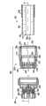
图1是根据本发明的部分组装同轴电缆连接器的一个实施例和波纹同轴电缆的一部分剖视图;1 is a partial cross-sectional view of one embodiment of a partially assembled coaxial cable connector and a corrugated coaxial cable according to the present invention;
图2是图1的同轴电缆的分解剖视图;Fig. 2 is an exploded sectional view of the coaxial cable of Fig. 1;
图3是图1连接器剖视图,其具有安装在同轴电缆上的后侧分组件和安装到后侧分组件之前的前侧分组件;3 is a cross-sectional view of the connector of FIG. 1 with the rear subassembly mounted on the coaxial cable and the front subassembly prior to installation to the rear subassembly;
图4是图1连接器的剖视图,同轴电缆连接器部分地安装在波纹同轴电缆上;Figure 4 is a cross-sectional view of the connector of Figure 1, with the coaxial cable connector partially mounted on the corrugated coaxial cable;
图5是图1连接器的剖视图,同轴电缆连接器完全地安装在波纹同轴电缆上;以及Figure 5 is a cross-sectional view of the connector of Figure 1 with the coaxial cable connector fully installed on the corrugated coaxial cable; and
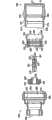
图6是根据本发明的同轴电缆连接器的另一个实施例的视图,该同轴电缆连接器完全安装在波纹同轴电缆的一部分上。Figure 6 is a view of another embodiment of a coaxial cable connector fully mounted on a portion of a corrugated coaxial cable in accordance with the present invention.
具体实施方式Detailed ways
现在将详细参照本发明的当前优选实施例,其实例在附图中示出。在全部附图中尽可能地使用相同的附图标记表示相同或相似的部件。Reference will now be made in detail to the presently preferred embodiments of the invention, examples of which are illustrated in the accompanying drawings. Wherever possible, the same reference numbers will be used throughout the drawings to refer to the same or like parts.
参考图1和2,示出波纹同轴电缆100的一部分和波纹同轴电缆连接器200的剖视图。波纹同轴电缆100包括中心导体105、电介质120、波纹外部导体125和护套130。中心导体105较佳地是环形并具有内径110和外径115。Referring to Figures 1 and 2, a cross-sectional view of a portion of a corrugated
波纹同轴电缆连接器200较佳地在工厂预组装并包括后侧分组件202和前侧分组件204。分组件202、204较佳地彼此附连以使它们可从工厂运到现场,如下文更详细描述的那样。The corrugated
后侧分组件202包括后外部本体206,后外部本体206具有前端208、后端210、外部夹紧部分212以及沿纵向轴线A在前端208与后端210之间延伸的纵向开口214。后外部本体206较佳地包括与前端208相邻的螺纹部分216以与前分组件204螺纹地配合。后外部本体206较佳地由诸如黄铜之类的金属材料制成并较佳的镀有例如镍锡合金之类的导电的、耐腐蚀材料。The
后侧分组件202还包括夹持件220,夹持件220较佳地由诸如乙缩醛之类的塑料材料制成,但也可由黄铜制成并镀有例如镍锡合金之类的导电的、耐腐蚀材料。夹持件220通过自由旋转的卡合固定在后外部本体206的纵向开口214内。较佳地,夹持件220在工厂固定在后外部本体206内。夹持件220具有前端222、后端224以及纵向开口226。在前端222处,夹持件220具有楔形部分228,楔形部分228通至纵向开口226的内表面232上的第一向内突起的突出部230。第二向内突起的突出部234也在内表面232上,并从第一向内突起的突出部230向后设置。较佳地,向内突起的突出部230是环形突出部并绕纵向开口226延伸。但是,它们也可以是分段的或不连续的且仍然是在本发明的范围内。如下文将更详细讨论的那样,向内突起的突出部230、234与波纹外部导体125配合,在配合处外部导体125具有最小的直径,即,波纹外部导体125的谷部。夹持件220的前端222较佳地具有多个狭槽240,致使前端222具有多个指状物或挠性梁242。挠性梁的存在使夹持件220能够在波纹同轴电缆100上滑过,且具体来说,在波纹外部导体125上滑过。The
前侧分组件204包括前体260,绝缘体300以及接触件320。前体260具有前端262、后端264、外部夹紧部分266以及沿纵向轴向A在前端262与后端264之间延伸的纵向开口268。前体260还具有倒圆的环形肩270和内螺纹部分272。如下文更详细描述的那样,倒圆环形肩270与夹持件220的楔形部分228协配来捕获波纹外部导体125以将连接器200固定到同轴电缆100上。内螺纹部分272与后外部本体206的螺纹部分216协配来固定后侧分组件202和前侧分组件204。前本体260较佳地由诸如黄铜之类的金属材料制成并较佳的镀有例如镍锡合金之类的导电的耐腐蚀材料。绝缘体300包括对准在纵向轴向A上的孔302和外表面284。绝缘体300由诸如乙缩醛之类电绝缘材料制成,并辅助对中和支承接触件320。接触件320具有后端322,后端322包括与中心导体105配合的锥形部分324。接触件320在其后端322也较佳地具有多个狭槽326,以使接触件320能够在需要时挠曲以和中心导体105物理和电接触。接触件320由诸如铍铜之类的金属材料制成,较佳地经过热处理,并较佳的镀有例如镍锡合金之类的导电的耐腐蚀材料。接触件320具有前端328,前端328具有接纳公构造接触件(未示出)的母构造。然而,接触件320的前端328也可具有公构造。The
多个密封件,较佳地是O型环形式,也在工厂安装到连接器200内以使连接件200防水。如图1所示,在后侧分组件206中,已安装密封件350、360和370。密封件350已安装在后外部本体206后端210处的环形挖切部352内。密封件350通过与同轴电缆100的护套130配合来辅助使连接器200防水(见图3)。密封件360安装在后外部本体206中间部分的环形挖切部362里,并密封夹持件220和后侧外部主体206之间的接合处。密封件370已在环形挖切部372内安装在后侧外部主体206外表面上,且如下面结合图5所指出的,当连接器组装到波纹同轴电缆100上时,密封后侧外部主体206与前侧主体260的接合处。A plurality of seals, preferably in the form of O-rings, are also factory installed into the
两密封件380、390也在工厂安装在前侧分组件204内,以从前侧密封连接器200。密封件380已在环形挖切部382内安装在接触件320上,以在当接触件320安装在绝缘体300内时密封连接器200。类似地,密封件390在工厂安装在绝缘体300的环形挖切部392内,以密封绝缘体300与前本体260之间的接合处。Two
现转向图3,现将描述波纹同轴电缆连接器200的安装。如尚未彼此分离,后侧分组件202和前侧分组件204应彼此分离,即,在较佳的实施例中彼此不拧紧。然后将后侧分组件202放置在波纹同轴电缆100上,该波纹同轴电缆100具有护套130,护套130向后剥以暴露出波纹外部导体125的一部分。夹持件220在波纹同轴电缆100上滑过,且具体来说,在波纹外部导体125上滑过,多个指状物或挠性梁242充分挠曲以使后侧分组件202能够在波纹同轴电缆100上滑动。后侧分组件202应自然地将夹持件220的纵向开口226的内表面232上的第一向内突起的突出部230靠在波纹外部导体125的环形沟槽内。第二向内突起的突出部234也在波纹外部导体125的环形沟槽内且密封件350与电缆护套130配合。Turning now to Figure 3, installation of the corrugated
如图4所示,前侧分组件204部分地安装在后侧分组件202上,其在该实施例中是通过将后侧分组件202和前侧分组件204相对于彼此转动来完成的。在安装过程中,接触件320与中心导体105的内径110对准并与之配合。锥形部分324确保接触件320与中心导体105形成物理和电接触。接触件320在一定程度上大于中心导体105的内径110,各狭槽326使接触件320能够径向压缩以配装在中心导体105内。同时,倒圆的环形肩270在波纹外部导体125和电介质120之间移动,以在倒圆的环形肩270和夹持件220的楔形部分228之间箍缩波纹外部导体125。As shown in FIG. 4, the
在图5中,后侧分组件202通过前本体260的内螺纹部分272和后侧体206的外螺纹部分219的进一步转动完全地拧入前侧分组件204。应当注意,因夹持件220是分离的构件(即自由转动构件),前侧主体260和后侧主体206的转动配合不会向夹持件220传递可感知的转动或扭转负载,因此防止损害夹持件220的挠性梁242。第一向内突起的突出部230和第二向内突起的突出部234分别在圆周点B和C处与波纹外部导体125接触,并将波纹外部导体125捕获在倒圆环形肩270与夹持件220的楔形部分228之间,从而在波纹外部导体125与前本体260之间提供有效的电力和机械的连通。第二向内突起的突出部234在圆周点C处与波纹外部导体125接触并提供附加的轴向负载和径向支承,从而进一步稳定连接器/电缆接合。通过第二向内突起的突出部234的附加径向支承尤其有助于提供张力释放并保证接合处长期的电力和机械稳定性。支撑电缆100的第三圆周点由密封件350和360提供,具体来说,因为密封件360通过前主体260到后外部本体206的连接向内变形。In FIG. 5 , the
图6示出根据本发明的波纹同轴电缆连接器600的另一个实施例。波纹同轴电缆连接器600类似于第一实施例并具有后外部本体606、夹持件620、前本体660、绝缘体700以及接触件720。波纹同轴电缆连接器600也具有相同的密封件,但其中夹持件620在其后端具有另外的向内突起的环形突出部650,以与波纹外部导体125配合并为同轴电缆100提供360度全范围的支承。FIG. 6 shows another embodiment of a corrugated
对本领域技术人员显而易见的是,可对本发明做出各种修改和变化而不偏离本发明的精神和范围。因此本发明旨在覆盖本发明的修改和变型,只要这些修改和变型在所附权利要求及其等价物的范围内。It will be apparent to those skilled in the art that various modifications and changes can be made in the present invention without departing from the spirit and scope of the invention. Thus, it is intended that the present invention covers the modifications and variations of this invention provided they come within the scope of the appended claims and their equivalents.
Claims (10)
Translated fromChineseApplications Claiming Priority (3)
| Application Number | Priority Date | Filing Date | Title |
|---|---|---|---|
| US401107P | 2007-11-21 | 2007-11-21 | |
| US61/004,011 | 2007-11-21 | ||
| PCT/US2008/009031WO2009067132A1 (en) | 2007-11-21 | 2008-07-25 | Coaxial cable connector for corrugated cable |
Publications (2)
| Publication Number | Publication Date |
|---|---|
| CN101919126A CN101919126A (en) | 2010-12-15 |
| CN101919126Btrue CN101919126B (en) | 2013-10-23 |
Family
ID=39745218
Family Applications (1)
| Application Number | Title | Priority Date | Filing Date |
|---|---|---|---|
| CN2008801241188AExpired - Fee RelatedCN101919126B (en) | 2007-11-21 | 2008-07-25 | Coaxial Cable Connectors for Corrugated Cables |
Country Status (7)
| Country | Link |
|---|---|
| US (1) | US7690945B2 (en) |
| EP (1) | EP2063501B1 (en) |
| CN (1) | CN101919126B (en) |
| DK (1) | DK2063501T3 (en) |
| PL (1) | PL2063501T3 (en) |
| TW (1) | TWI389400B (en) |
| WO (1) | WO2009067132A1 (en) |
Families Citing this family (15)
| Publication number | Priority date | Publication date | Assignee | Title |
|---|---|---|---|---|
| US8460031B2 (en)* | 2008-11-05 | 2013-06-11 | Andrew Llc | Coaxial connector with cable diameter adapting seal assembly and interconnection method |
| US7803018B1 (en)* | 2009-03-10 | 2010-09-28 | Andrew Llc | Inner conductor end contacting coaxial connector and inner conductor adapter kit |
| EP2438655A1 (en)* | 2009-06-05 | 2012-04-11 | Andrew LLC | Slip ring contact coaxial connector |
| US20110117777A1 (en)* | 2009-11-16 | 2011-05-19 | Thomas & Betts International, Inc. | Cable connector |
| US9166306B2 (en) | 2010-04-02 | 2015-10-20 | John Mezzalingua Associates, LLC | Method of terminating a coaxial cable |
| US7934954B1 (en) | 2010-04-02 | 2011-05-03 | John Mezzalingua Associates, Inc. | Coaxial cable compression connectors |
| US8177582B2 (en) | 2010-04-02 | 2012-05-15 | John Mezzalingua Associates, Inc. | Impedance management in coaxial cable terminations |
| US8468688B2 (en) | 2010-04-02 | 2013-06-25 | John Mezzalingua Associates, LLC | Coaxial cable preparation tools |
| WO2011146441A1 (en)* | 2010-05-19 | 2011-11-24 | Corning Gilbert Inc. | Coaxial connector for corrugated cable with integral clamping and sealing member |
| DE202010011857U1 (en)* | 2010-08-25 | 2010-10-28 | Ccs Cable Connector Systems Gmbh | Plug, in particular photovoltaic plug |
| DE102010037193A1 (en)* | 2010-08-27 | 2012-03-01 | Phoenix Contact Gmbh & Co. Kg | Cable strain relief |
| US8657626B2 (en)* | 2010-12-02 | 2014-02-25 | Thomas & Betts International, Inc. | Cable connector with retaining element |
| CN103794899A (en)* | 2012-10-26 | 2014-05-14 | 江苏正恺电子科技有限公司 | Radio frequency connector with center conductor having sudden change |
| CN109904687B (en)* | 2019-02-18 | 2020-09-08 | 苏州华旃航天电器有限公司 | Novel high-temperature-resistant high-pressure water vapor-sealed N-K type terminating cable radio-frequency coaxial connector |
| WO2022150713A1 (en)* | 2021-01-08 | 2022-07-14 | Corning Optical Communications Rf Llc | Coaxial connector assembly having locking ferrule |
Citations (3)
| Publication number | Priority date | Publication date | Assignee | Title |
|---|---|---|---|---|
| DE3422549A1 (en)* | 1984-06-18 | 1985-12-19 | Georg Dr.-Ing. 8152 Feldkirchen-Westerham Spinner | Plug for coaxial cables |
| DE9400943U1 (en)* | 1993-03-25 | 1994-04-07 | Spinner GmbH Elektrotechnische Fabrik, 80335 München | Connector for coaxial cable with corrugated tube outer conductor |
| CN1291811A (en)* | 1999-09-22 | 2001-04-18 | 三菱电线工业株式会社 | Connector structure |
Family Cites Families (26)
| Publication number | Priority date | Publication date | Assignee | Title |
|---|---|---|---|---|
| US3199061A (en) | 1963-01-31 | 1965-08-03 | Andrew Corp | Coaxial connector |
| US3291895A (en) | 1964-05-05 | 1966-12-13 | Andrew Corp | Coaxial cable connectors |
| US4046451A (en) | 1976-07-08 | 1977-09-06 | Andrew Corporation | Connector for coaxial cable with annularly corrugated outer conductor |
| US5154636A (en) | 1991-01-15 | 1992-10-13 | Andrew Corporation | Self-flaring connector for coaxial cable having a helically corrugated outer conductor |
| US5137470A (en) | 1991-06-04 | 1992-08-11 | Andrew Corporation | Connector for coaxial cable having a helically corrugated inner conductor |
| FR2682819B1 (en) | 1991-10-21 | 1994-09-30 | Signal Engineering Electronics | CONNECTOR FOR COAXIAL CABLES. |
| US5167533A (en) | 1992-01-08 | 1992-12-01 | Andrew Corporation | Connector for coaxial cable having hollow inner conductors |
| DE4207482C1 (en) | 1992-03-10 | 1993-07-08 | Wilhelm Sihn Jun. Kg, 7532 Niefern-Oeschelbronn, De | Forming flanged rim in waveguide of coaxial cable - allowing armature to be mounted with bearing clamped to fit in troughs of waveguide pushed to abut bearing |
| US5435745A (en) | 1994-05-31 | 1995-07-25 | Andrew Corporation | Connector for coaxial cable having corrugated outer conductor |
| DE19738733C1 (en) | 1997-09-04 | 1999-06-17 | Spinner Gmbh Elektrotech | Connector for coaxial cable with ring-corrugated outer conductor |
| US6109964A (en) | 1998-04-06 | 2000-08-29 | Andrew Corporation | One piece connector for a coaxial cable with an annularly corrugated outer conductor |
| EP0975051A1 (en) | 1998-07-24 | 2000-01-26 | Cabel-Con A/S | Connector for coaxial cable with multiple start threads |
| DE19846440A1 (en) | 1998-10-08 | 2000-04-20 | Spinner Gmbh Elektrotech | Connector for coaxial cable with ring-corrugated outer conductor |
| DE19857528C2 (en) | 1998-12-14 | 2002-06-20 | Spinner Gmbh Elektrotech | Connector for coaxial cable with ring-corrugated outer conductor |
| EP1122835A1 (en) | 2000-02-04 | 2001-08-08 | Cabel-Con A/S | One piece connector |
| EP1148592A1 (en) | 2000-04-17 | 2001-10-24 | Cabel-Con A/S | Connector for a coaxial cable with corrugated outer conductor |
| EP1170833A1 (en) | 2000-07-07 | 2002-01-09 | Cabel-Con A/S | Connector for coaxial cable with a helically corrugated outer conductor |
| US6824415B2 (en) | 2001-11-01 | 2004-11-30 | Andrew Corporation | Coaxial connector with spring loaded coupling mechanism |
| ATE336808T1 (en)* | 2002-06-22 | 2006-09-15 | Spinner Gmbh Elektrotech | COAXIAL CONNECTOR |
| US7134189B2 (en) | 2002-09-12 | 2006-11-14 | Andrew Corporation | Coaxial cable connector and tool and method for connecting a coaxial cable |
| US6840803B2 (en) | 2003-02-13 | 2005-01-11 | Andrew Corporation | Crimp connector for corrugated cable |
| US6994587B2 (en) | 2003-07-23 | 2006-02-07 | Andrew Corporation | Coaxial cable connector installable with common tools |
| US7249969B2 (en) | 2003-07-28 | 2007-07-31 | Andrew Corporation | Connector with corrugated cable interface insert |
| US7217154B2 (en) | 2005-10-19 | 2007-05-15 | Andrew Corporation | Connector with outer conductor axial compression connection and method of manufacture |
| US7275957B1 (en) | 2006-03-22 | 2007-10-02 | Andrew Corporation | Axial compression electrical connector for annular corrugated coaxial cable |
| US7189114B1 (en) | 2006-06-29 | 2007-03-13 | Corning Gilbert Inc. | Compression connector |
- 2008
- 2008-07-25WOPCT/US2008/009031patent/WO2009067132A1/enactiveApplication Filing
- 2008-07-25CNCN2008801241188Apatent/CN101919126B/ennot_activeExpired - Fee Related
- 2008-08-07EPEP08162022.1Apatent/EP2063501B1/enactiveActive
- 2008-08-07PLPL08162022Tpatent/PL2063501T3/enunknown
- 2008-08-07DKDK08162022.1Tpatent/DK2063501T3/enactive
- 2008-11-05USUS12/265,286patent/US7690945B2/enactiveActive
- 2008-11-18TWTW097144612Apatent/TWI389400B/ennot_activeIP Right Cessation
Patent Citations (3)
| Publication number | Priority date | Publication date | Assignee | Title |
|---|---|---|---|---|
| DE3422549A1 (en)* | 1984-06-18 | 1985-12-19 | Georg Dr.-Ing. 8152 Feldkirchen-Westerham Spinner | Plug for coaxial cables |
| DE9400943U1 (en)* | 1993-03-25 | 1994-04-07 | Spinner GmbH Elektrotechnische Fabrik, 80335 München | Connector for coaxial cable with corrugated tube outer conductor |
| CN1291811A (en)* | 1999-09-22 | 2001-04-18 | 三菱电线工业株式会社 | Connector structure |
Also Published As
| Publication number | Publication date |
|---|---|
| EP2063501A1 (en) | 2009-05-27 |
| DK2063501T3 (en) | 2016-11-14 |
| CN101919126A (en) | 2010-12-15 |
| US20090130900A1 (en) | 2009-05-21 |
| US7690945B2 (en) | 2010-04-06 |
| PL2063501T3 (en) | 2017-02-28 |
| WO2009067132A1 (en) | 2009-05-28 |
| EP2063501B1 (en) | 2016-10-05 |
| TWI389400B (en) | 2013-03-11 |
| TW200939580A (en) | 2009-09-16 |
Similar Documents
| Publication | Publication Date | Title |
|---|---|---|
| CN101919126B (en) | Coaxial Cable Connectors for Corrugated Cables | |
| US7811133B2 (en) | Shielded electrical connector with a spring arrangement | |
| US8016615B2 (en) | Phone plug connector device | |
| CN102341964A (en) | Coaxial cable connector including flexible fingers and related methods | |
| US9270046B2 (en) | Seal for helical corrugated outer conductor | |
| CN105340134A (en) | Quick-install connectors for coaxial cables | |
| JP2009049009A (en) | Hollow inner conductor contact for coaxial cable connector | |
| US10381791B2 (en) | Coaxial cable connector | |
| US11677172B2 (en) | Easily assembled coaxial cable and connector with rear body | |
| US7867025B2 (en) | Cable connector with supported center conductor contact | |
| US9033730B2 (en) | Coaxial cable connector and method of making same | |
| US10637172B2 (en) | Coaxial male connector, coaxial female connector and assembly thereof | |
| EP4457906A1 (en) | Connector for providing more reliable signal propagation by maintaining conductor pin contact at certain perimeter portions thereof | |
| CN120016206A (en) | A wiring harness connector | |
| CN107078407A (en) | Coaxial Cable and Connector Assemblies | |
| US7682201B2 (en) | Cable connector plug having contact with curved extension portion | |
| US20210167563A1 (en) | Coaxial cable assemblies having pinching and gripping elements | |
| US9647384B2 (en) | Back body for coaxial connector | |
| WO2011146441A1 (en) | Coaxial connector for corrugated cable with integral clamping and sealing member | |
| US20220385009A1 (en) | Coaxial cable and connector with adapter to facilitate assembly | |
| US20230246350A1 (en) | Coaxial connector with grounding and retention | |
| JPS59134577A (en) | Solderless connector for semirigid coaxial cable | |
| JP2015156282A (en) | coaxial connector | |
| EP3949033A1 (en) | An electrical connector for a bus bar | |
| CN114902504A (en) | Clamp assembly for RF compression connector |
Legal Events
| Date | Code | Title | Description |
|---|---|---|---|
| C06 | Publication | ||
| PB01 | Publication | ||
| C10 | Entry into substantive examination | ||
| SE01 | Entry into force of request for substantive examination | ||
| C14 | Grant of patent or utility model | ||
| GR01 | Patent grant | ||
| CF01 | Termination of patent right due to non-payment of annual fee | Granted publication date:20131023 Termination date:20200725 | |
| CF01 | Termination of patent right due to non-payment of annual fee |