CN101918893B - Method and apparatus with depth map generation - Google Patents
Method and apparatus with depth map generationDownload PDFInfo
- Publication number
- CN101918893B CN101918893BCN2008801227570ACN200880122757ACN101918893BCN 101918893 BCN101918893 BCN 101918893BCN 2008801227570 ACN2008801227570 ACN 2008801227570ACN 200880122757 ACN200880122757 ACN 200880122757ACN 101918893 BCN101918893 BCN 101918893B
- Authority
- CN
- China
- Prior art keywords
- lens position
- depth map
- image
- lens
- group
- Prior art date
- Legal status (The legal status is an assumption and is not a legal conclusion. Google has not performed a legal analysis and makes no representation as to the accuracy of the status listed.)
- Active
Links
Images


Classifications
- H—ELECTRICITY
- H04—ELECTRIC COMMUNICATION TECHNIQUE
- H04N—PICTORIAL COMMUNICATION, e.g. TELEVISION
- H04N13/00—Stereoscopic video systems; Multi-view video systems; Details thereof
- H04N13/20—Image signal generators
- H04N13/204—Image signal generators using stereoscopic image cameras
- H04N13/207—Image signal generators using stereoscopic image cameras using a single 2D image sensor
- H04N13/236—Image signal generators using stereoscopic image cameras using a single 2D image sensor using varifocal lenses or mirrors
- G—PHYSICS
- G02—OPTICS
- G02B—OPTICAL ELEMENTS, SYSTEMS OR APPARATUS
- G02B27/00—Optical systems or apparatus not provided for by any of the groups G02B1/00 - G02B26/00, G02B30/00
- G02B27/0075—Optical systems or apparatus not provided for by any of the groups G02B1/00 - G02B26/00, G02B30/00 with means for altering, e.g. increasing, the depth of field or depth of focus
- G—PHYSICS
- G06—COMPUTING OR CALCULATING; COUNTING
- G06T—IMAGE DATA PROCESSING OR GENERATION, IN GENERAL
- G06T7/00—Image analysis
- G06T7/50—Depth or shape recovery
- G06T7/55—Depth or shape recovery from multiple images
- G06T7/571—Depth or shape recovery from multiple images from focus
- H—ELECTRICITY
- H04—ELECTRIC COMMUNICATION TECHNIQUE
- H04N—PICTORIAL COMMUNICATION, e.g. TELEVISION
- H04N13/00—Stereoscopic video systems; Multi-view video systems; Details thereof
- H04N13/10—Processing, recording or transmission of stereoscopic or multi-view image signals
- H04N13/106—Processing image signals
- H04N13/161—Encoding, multiplexing or demultiplexing different image signal components
- H—ELECTRICITY
- H04—ELECTRIC COMMUNICATION TECHNIQUE
- H04N—PICTORIAL COMMUNICATION, e.g. TELEVISION
- H04N13/00—Stereoscopic video systems; Multi-view video systems; Details thereof
- H04N13/10—Processing, recording or transmission of stereoscopic or multi-view image signals
- H04N13/194—Transmission of image signals
- H—ELECTRICITY
- H04—ELECTRIC COMMUNICATION TECHNIQUE
- H04N—PICTORIAL COMMUNICATION, e.g. TELEVISION
- H04N23/00—Cameras or camera modules comprising electronic image sensors; Control thereof
- H04N23/60—Control of cameras or camera modules
- H04N23/67—Focus control based on electronic image sensor signals
- H04N23/673—Focus control based on electronic image sensor signals based on contrast or high frequency components of image signals, e.g. hill climbing method
- H—ELECTRICITY
- H04—ELECTRIC COMMUNICATION TECHNIQUE
- H04N—PICTORIAL COMMUNICATION, e.g. TELEVISION
- H04N23/00—Cameras or camera modules comprising electronic image sensors; Control thereof
- H04N23/60—Control of cameras or camera modules
- H04N23/67—Focus control based on electronic image sensor signals
- H04N23/676—Bracketing for image capture at varying focusing conditions
- H—ELECTRICITY
- H04—ELECTRIC COMMUNICATION TECHNIQUE
- H04N—PICTORIAL COMMUNICATION, e.g. TELEVISION
- H04N23/00—Cameras or camera modules comprising electronic image sensors; Control thereof
- H04N23/70—Circuitry for compensating brightness variation in the scene
- H04N23/743—Bracketing, i.e. taking a series of images with varying exposure conditions
- G—PHYSICS
- G06—COMPUTING OR CALCULATING; COUNTING
- G06T—IMAGE DATA PROCESSING OR GENERATION, IN GENERAL
- G06T2207/00—Indexing scheme for image analysis or image enhancement
- G06T2207/10—Image acquisition modality
- G06T2207/10004—Still image; Photographic image
- G06T2207/10012—Stereo images
- G—PHYSICS
- G06—COMPUTING OR CALCULATING; COUNTING
- G06T—IMAGE DATA PROCESSING OR GENERATION, IN GENERAL
- G06T2207/00—Indexing scheme for image analysis or image enhancement
- G06T2207/10—Image acquisition modality
- G06T2207/10016—Video; Image sequence
- H—ELECTRICITY
- H04—ELECTRIC COMMUNICATION TECHNIQUE
- H04N—PICTORIAL COMMUNICATION, e.g. TELEVISION
- H04N2213/00—Details of stereoscopic systems
- H04N2213/003—Aspects relating to the "2D+depth" image format
Landscapes
- Engineering & Computer Science (AREA)
- Multimedia (AREA)
- Signal Processing (AREA)
- Physics & Mathematics (AREA)
- General Physics & Mathematics (AREA)
- Optics & Photonics (AREA)
- Computer Vision & Pattern Recognition (AREA)
- Theoretical Computer Science (AREA)
- Studio Devices (AREA)
- Automatic Focus Adjustment (AREA)
- Focusing (AREA)
Abstract
Description
Translated fromChinese背景技术Background technique
采用固定焦距的数码相机被用于例如手机、膝上型计算机和其它装置等的移动装置中。这些相机具有造成短且固定的焦距的广角透镜。自动对焦操作是已知的,其中手机或数码相机的用户可半按下按钮以自动对焦图像,随后用户可接着继续按下按钮到完全按压位置以捕获最终图像。然而,已知的自动对焦操作可能以均匀方式(例如在其例如255个位置的整个范围内每25个位置)移动透镜,且在25个位置的每个均匀透镜位置处捕获图像,从而导致处理10到12个帧。捕获自动对焦算法借以确定最佳图像的大约10个图像可导致对移动装置的电力耗用且随着时间的过去而急剧影响电池使用。另外,如果使用闪光灯来拍摄最终图像,那么当闪光灯可能实际上不必要或有用时,额外的电力耗用可使移动装置的性能降级。另外,在均匀的对焦透镜位置方案下,为了自动对焦确定可能拍摄10或12个帧,这要求装置捕获且处理许多帧。这可要求额外的处理时间且用户可能必须等待不必要的时间量以等待自动对焦操作完成。Digital cameras employing a fixed focal length are used in mobile devices such as cell phones, laptop computers, and other devices. These cameras have wide-angle lenses resulting in a short and fixed focal length. Autofocus operations are known where a user of a cell phone or digital camera can press a button halfway to autofocus an image, and then the user can then continue to press the button to the fully depressed position to capture the final image. However, known autofocus operations may move the lens in a uniform manner (e.g., every 25 positions over its entire range of, say, 255 positions), and capture an image at each uniform lens position of the 25 positions, resulting in processing 10 to 12 frames. Capturing the approximately 10 images by which the autofocus algorithm determines the best image can result in power drain on the mobile device and drastically impact battery usage over time. Additionally, if a flash is used to capture the final image, the additional power consumption can degrade the performance of the mobile device when the flash may not actually be necessary or useful. Additionally, with a uniform focus lens position scheme, perhaps 10 or 12 frames are taken for autofocus determination, requiring the device to capture and process many frames. This may require additional processing time and the user may have to wait an unnecessary amount of time for the autofocus operation to complete.
还已知使用不均匀透镜位置作为自动对焦过程的部分。举例来说,为了找到最佳透镜位置,可使用各种自动对焦搜索策略。这些方法确定如何更新透镜位置(更新多少且在哪个方向上更新)。搜索方法可影响自动对焦过程的速度和准确性。用以找到最佳透镜位置的透镜位置集合可基于不均匀(或均匀)间隔。不均匀透镜位置通常是基于对焦量度值的所确定的改变速率而在操作中(on the fly)动态确立。也就是说,如果对焦量度值的改变速率由装置中的过程确定为高,那么使用较短的透镜位置间隔,而如果对焦量度值改变的速率较低,那么使用较长的间隔。然而,可能难以确定改变速率且接着确定要使用的合适间隔。It is also known to use non-uniform lens positions as part of the autofocus process. For example, to find the best lens position, various autofocus search strategies can be used. These methods determine how to update the lens position (how much and in which direction). The search method can affect the speed and accuracy of the autofocus process. The set of lens positions used to find the optimal lens position may be based on non-uniform (or uniform) spacing. The non-uniform lens position is typically dynamically established on the fly based on the determined rate of change of the focus metric value. That is, a shorter lens position interval is used if the rate of change of the focus metric value is determined to be high by a process in the device, and a longer interval is used if the rate of change of the focus metric value is low. However, it can be difficult to determine the rate of change and then the appropriate interval to use.
改进自动对焦速度且减少对移动装置或非移动装置的电力耗用是极为重要的,尤其是在对移动装置的使用急剧增加时。对这些改进的需要已存在多年。然而,已知的当前解决方案仍可能要求不必要的时间量和/或电力消耗。Improving auto-focus speed and reducing power consumption on mobile or non-mobile devices is extremely important, especially when the usage of mobile devices increases dramatically. The need for these improvements has existed for many years. However, known current solutions may still require an unnecessary amount of time and/or power consumption.
关于深度图产生,多相机图像处理系统(例如,经校准的立体视觉系统)可采用多个相机,所述相机各自采用透镜来产生包含视场的若干所关注区的图像深度图以用于不同应用(例如在用于导引车辆的自动化车辆导引系统中)。使用这些系统产生深度图可导致要求使用多个预校准相机的高度复杂且昂贵的过程。然而,还需要使用较简单的深度图产生(例如,将视场分段为前景和背景)以改善各种数码相机功能/操作,例如对闪光/不闪光选择的更有效使用、更好的曝光估计、更有效的白平衡和改进的颜色校正矩阵选择。With respect to depth map generation, a multi-camera image processing system (e.g., a calibrated stereo vision system) may employ multiple cameras each employing a lens to generate an image depth map containing several regions of interest of the field of view for different applications (eg in automated vehicle guidance systems for guiding vehicles). Producing depth maps using these systems can result in a highly complex and expensive process requiring the use of multiple pre-calibrated cameras. However, there is also a need for simpler depth map generation (e.g. segmenting the field of view into foreground and background) to improve various digital camera functions/operations, e.g. more efficient use of flash/no-flash selection, better exposure Estimation, more efficient white balance and improved color correction matrix selection.
附图说明Description of drawings
鉴于由以下图式伴随的以下描述将更容易理解本发明,且其中相同参考标号表示相同元件,其中:The invention will be more readily understood in view of the following description accompanied by the following drawings, in which like reference numerals refer to like elements, in which:
图1是说明根据本发明一个实施例的自动对焦电路的一个实例的框图;1 is a block diagram illustrating an example of an autofocus circuit according to an embodiment of the present invention;
图2是说明根据本发明中陈述的实例的用于改进自动对焦系统的方法的一个实例的流程图;FIG. 2 is a flowchart illustrating one example of a method for improving an autofocus system according to the examples set forth in this disclosure;
图3是展示根据本发明中陈述的一个实施例的预定不均匀对焦位置数据的一个实例的说明;FIG. 3 is an illustration showing an example of predetermined non-uniform focus position data according to an embodiment set forth in the present invention;
图4是说明根据本发明中的一个实例的移动装置的一个实例的框图;Figure 4 is a block diagram illustrating an example of a mobile device according to an example in the present invention;
图5是说明根据本发明中陈述的一个实例的用于改进自动对焦系统的方法的一个实例的流程图;5 is a flowchart illustrating an example of a method for improving an autofocus system according to an example set forth in this disclosure;
图6是说明根据本发明中陈述的一个实例的采用深度图产生逻辑的设备的一个实例的框图;6 is a block diagram illustrating an example of a device employing depth map generation logic according to an example set forth in this disclosure;
图7是说明根据本发明中陈述的一个实例的深度图产生逻辑的一个实例的框图;7 is a block diagram illustrating an example of depth map generation logic according to an example set forth in this disclosure;
图8是说明根据本发明中陈述的一个实例的用于改进数码相机图像产生的方法的一个实例的流程图;8 is a flowchart illustrating an example of a method for improving digital camera image production according to an example set forth in this disclosure;
图9说明根据本发明中陈述的一个实例的用以产生从多个图像导出的深度图的数据的一个实例;Figure 9 illustrates an example of data used to generate a depth map derived from multiple images according to an example set forth in this disclosure;
图10是说明根据本发明中陈述的一个实例的用于改进数码相机图像产生的方法的一个实例的流程图;10 is a flowchart illustrating an example of a method for improving digital camera image production according to an example set forth in this disclosure;
图11是说明根据本发明的传达深度图信息的系统的一个实例的框图;以及11 is a block diagram illustrating one example of a system for conveying depth map information according to the present invention; and
图12说明根据本发明中的一个实例的可用以产生深度图的位置数据的一个实例。12 illustrates one example of position data that may be used to generate a depth map, according to one example in this disclosure.
具体实施方式Detailed ways
大体上,揭示一种设备和方法,其中使用单个相机(例如,相机的单个透镜)产生深度图且由相机捕获多个图像。在一个实例中,使用单个数码相机捕获对应于基于透镜位置数据的一组透镜位置的一组图像。在此实例中,透镜位置数据可为均匀或不均匀的透镜位置数据。所述方法和设备确定一组图像中的每一图像中的多个关注区中的每一者的对焦量度信息。基于来自所述组中的图像的对焦量度信息确定关注区中的每一者的最佳透镜位置,且将其作为数据存储于深度图中。随后基于产生的深度图而执行图像产生操作,例如确定是否使用闪光灯来捕获最终图像、确定将对最终图像执行的颜色操作的类型、或任何其它合适的图像产生操作。在一个实例中,深度图是通过在捕获的各个图像中选择针对特定关注区的最佳对焦量度而产生。一旦使用来自多个图像的数据产生深度图,则基于深度图的控制逻辑就确定如何使用深度图来实现图像处理操作。In general, an apparatus and method are disclosed in which a single camera (eg, a single lens of the camera) is used to generate a depth map and multiple images are captured by the camera. In one example, a single digital camera is used to capture a set of images corresponding to a set of lens positions based on lens position data. In this example, the lens position data may be uniform or non-uniform lens position data. The method and apparatus determine focus metric information for each of a plurality of regions of interest in each image of a set of images. The optimal lens position for each of the regions of interest is determined based on the focus metric information from the images in the set and stored as data in the depth map. Image generation operations are then performed based on the generated depth map, such as determining whether to use a flash to capture the final image, determining the type of color manipulation to be performed on the final image, or any other suitable image generation operation. In one example, the depth map is generated by selecting the best focus metric for a particular region of interest in the various captured images. Once the depth map is generated using data from the plurality of images, control logic based on the depth map determines how to implement image processing operations using the depth map.
除了其它优点外,无需采用多个相机,也无需采用外部光传感器来产生用于在图像处理操作中使用的深度图。所属领域的技术人员将认识到其它优点。Among other advantages, there is no need to employ multiple cameras, nor to employ an external light sensor to generate a depth map for use in image processing operations. Those skilled in the art will recognize other advantages.
在其它实施例中,方法和设备通过更改(例如通过定位)数码相机的至少一个透镜到对应于预定不均匀透镜位置数据的多个预定不均匀透镜位置且基于预定不均匀透镜位置数据而选择透镜的透镜位置来改进自动对焦系统。预定不均匀透镜位置数据可(例如)被预定,且可存储在存储器中,可经由电阻性阵列提供,或可以任何合适方式提供。预定不均匀透镜位置数据表示可用以对焦以拍摄最终图像的最少数目或组的最佳透镜位置,其被事先确定且基于特定相机透镜的光学特性。在一个实例中,所述数据表示对应于透镜位置对距参考点的物距(例如,针对固定焦距透镜,沿着最佳透镜位置的特性曲线的点对物距)的关系的经验上获得的信息。在一个实例中,固定数目的预定义不均匀透镜位置定义了用以在自动对焦操作期间捕获图像的一组最佳不均匀透镜位置。最终图像是使用这些预定不均匀透镜位置中的一者捕获的。来自所述组预定不均匀透镜位置的最佳对焦透镜位置是通过比较来自在各个不均匀对焦透镜位置处获得的帧中的每一者的对焦量度信息且选择具有例如最佳对焦量度的帧作为将用于最终图片或图像捕获的透镜位置而确定的。可按需要基于每帧或每关注区而产生对焦量度信息。In other embodiments, methods and apparatus select a lens based on predetermined non-uniform lens position data by altering (e.g., by positioning) at least one lens of a digital camera to a plurality of predetermined non-uniform lens positions corresponding to predetermined non-uniform lens position data lens position to improve the autofocus system. Predetermined non-uniform lens position data may, for example, be predetermined, and may be stored in memory, may be provided via a resistive array, or may be provided in any suitable manner. The predetermined non-uniform lens position data represents the minimum number or set of optimal lens positions that can be used to focus to capture the final image, which is determined in advance and based on the optical characteristics of the particular camera lens. In one example, the data represent an empirically obtained relationship corresponding to lens position versus object distance from a reference point (e.g., point-to-object distance along a characteristic curve of optimal lens position for a fixed focal length lens). information. In one example, a fixed number of predefined non-uniform lens positions defines an optimal set of non-uniform lens positions to capture images during an auto-focus operation. The final image is captured using one of these predetermined non-uniform lens positions. The best focus lens position from the set of predetermined non-uniform focus lens positions is obtained by comparing the focus metric information from each of the frames obtained at the respective non-uniform focus lens positions and selecting the frame with, for example, the best focus metric as The lens position that will be used for final picture or image capture is determined. Focus metric information can be generated on a per frame or per region of interest basis as desired.
除了其它优点外,与采用(例如)基于均匀透镜位置的图像采样的系统相比,可导致较快的自动对焦过程,且需要获得较少数目的图像来确定最佳透镜位置。而且,使用一组预定不均匀透镜位置去除了对任何动态不均匀透镜位置确定和间隔确定过程的需要。由此,使用从所述组预定不均匀透镜位置中的一个或一个以上位置获得的图像的较少帧可加速自动对焦过程,使得用户无需等待长时间直到捕获图像,且可导致对装置电池的较低电力消耗,进而改进性能。Among other advantages, a faster autofocus process can result and a fewer number of images need to be acquired to determine an optimal lens position than systems employing, for example, uniform lens position based image sampling. Furthermore, the use of a predetermined set of non-uniform lens positions removes the need for any dynamic non-uniform lens position determination and spacing determination processes. Thus, using fewer frames of images obtained from one or more of the set of predetermined non-uniform lens positions can speed up the autofocus process so that the user does not have to wait a long time until an image is captured and can result in damage to the device battery Lower power consumption improves performance.
如本文使用,术语“模块”、“电路”、“逻辑”、“驱动器”和/或“级”可包含电子电路、执行存储在存储器中的一个或一个以上软件或固件程序的一个或一个以上处理器(例如,共享、专用或处理器群组,例如但不限于微处理器、DSP或中央处理单元)、组合逻辑电路、ASIC和/或提供所描述功能性的其它合适组件。As used herein, the terms "module," "circuit," "logic," "driver," and/or "stage" may include an electronic circuit, one or more Processors (eg, shared, dedicated, or groups of processors such as, but not limited to, microprocessors, DSPs, or central processing units), combinational logic circuits, ASICs, and/or other suitable components that provide the described functionality.
图1说明设备10,其包含展示为自动对焦控制逻辑12的电路、含有预定不均匀透镜位置数据18的存储器14,和例如具有固定焦距透镜的单个数码相机的相机16。然而,可采用任何合适的相机。设备10可例如为其中集成有数码相机的手机、手持式数码相机,或采用数码相机或者直接或间接与数码相机连接的任何合适装置。自动对焦控制逻辑12可实施为任何合适的结构,其包含(但不限于)离散逻辑、执行所存储的计算机可读指令的一个或一个以上处理器或任何其它合适结构。存储器14可为呈任何合适形式的RAM、ROM(例如寄存器、可寻址存储器),或可为任何其它合适的存储器,包含主机系统存储器、局部高速缓存存储器或按需要的任何其它合适存储器。预定不均匀透镜位置数据18也可以电阻器阵列的形式提供,所述阵列将电压电平提供到例如集成电路的输入端口,指示给定相机的不均匀透镜位置数据。数码相机的每一制造商可具有不同的特性且由此,可取决于使用的特定相机来采用不同的预定不均匀透镜位置数据。1 illustrates a
还参看图2和3,说明可例如由自动对焦控制逻辑12和设备10实施的方法。另外,图形说明展示了预定不均匀透镜位置数据18(八个非零点),其值可存储在存储器14中或者经由电阻器阵列或以任何其它合适方式提供。此信息可经由对设备10中的相机16的经验测试而事先获得,或可以任何其它合适方式获得。由此,数据可经由因特网或其它网络下载,或者可存储在例如存储器14的EEPROM中或经由任何合适方式提供到自动对焦控制逻辑12。如图示,预定不均匀透镜位置数据18表示(例如)依据步长数目(例如总共255个定位步长中的定位步长数目)的透镜位置与在给定透镜位置处经确定的距相机的物距(物体在所述位置处在焦点上)举例来说,展示了如果物距为距相机118cm,那么使用近似155的预定不均匀透镜位置。已发现,物体距相机越近,需要用4个透镜位置来进行自动对焦操作。举例来说,如果物距为100cm,那么使用第5个透镜位置。Referring also to FIGS. 2 and 3 , a method that may be implemented, for example, by
参看图2,方法包含(如图示)在步骤202中将相机16的透镜定位或更改到对应于预定不均匀透镜位置数据18的多个不均匀透镜位置。由此,自动对焦控制逻辑12将预定不均匀透镜位置控制信息20发送到相机16以例如定位相机,相机随后在透镜处于此位置时捕获图像且将在透镜处于不均匀透镜位置18中的一者处时获得的图像或帧22传达回。每一被接收的所捕获图像随后由自动对焦控制逻辑12分析以基于帧或子帧而确定图像清晰度量度信息,例如指示在给定透镜位置处图像有多清晰的值。给定图像的此值可随后临时存储在存储器中。自动对焦控制逻辑随后使用预定不均匀透镜位置控制信息20将透镜移动到下一所需透镜位置,且相机16在此透镜位置捕获另一图像。随后获得所述新的帧的清晰度图像量度信息,且将其与先前图像的先前图像对焦量度比较。如果确定其为较清晰的图像,那么将其存储以供与下一所捕获图像进行比较。随后取决于自动对焦过程正在使用爬山(hill climbing)方法、完整搜索方法或是其它方法,所述过程针对由预定不均匀位置数据18识别的每一所需不均匀透镜位置继续。如框204中所示,方法包含通过(例如)选取产生具有最佳图像清晰度量度的帧的透镜位置而基于不均匀透镜位置而选择最佳透镜位置。随后将此透镜位置用作用以捕获用户希望捕获的最终图像的透镜位置。预定不均匀透镜位置数据18可例如存储为存储器14中的查找表以在在线自动对焦过程期间使用。Referring to FIG. 2 , the method includes (as shown) positioning or altering the lens of
与其它已知系统相比,上述过程可导致较快的自动对焦过程,因为与使用均匀透镜位置(例如每25个步长)的自动对焦系统的典型的(例如)最多11个帧相反,仅需要捕获或评估最多7或8个帧(每一不均匀透镜位置处一个)。这还可导致较少的电力消耗,因为作为自动对焦过程的部分,捕获和分析较少的帧。所属领域的技术人员将认识到其它优点。The above process can result in a faster autofocus process compared to other known systems, since only A maximum of 7 or 8 frames (one at each non-uniform lens location) need to be captured or evaluated. This can also result in less power consumption because fewer frames are captured and analyzed as part of the autofocus process. Those skilled in the art will recognize other advantages.
将认识到,可以任何合适方式获得预定不均匀位置数据18。一种技术可为例如针对手机相机或具有固定焦距的其它相机确立弥散圆的可接受大小。不同的相机制造商可具有不同的弥散圆(直径以微米为单位)。此信息可由制造商提供或通过此项技术中已知的实验来确定。也可确定景深对透镜位置的关系,且将景深重叠而覆盖完整对焦范围的焦点距离用作不均匀透镜位置。举例来说,对于具有5.6mm×4.2mm大小的透镜(传感器),透镜焦距可为5.6mm且弥散圆大小可估计为9.5微米。可使用1,179mm的超焦距(hyper focal length)。由此,最佳透镜位置在图3中被展示为由预定不均匀位置数据18识别。不均匀透镜位置数据18表示与(例如)图3所示的透镜特性曲线相关联的不均匀透镜位置(或移动步长)。It will be appreciated that the predetermined
作为一个实例,可如下针对手机相机确立图3的预定不均匀透镜位置(及因此对应的数据18)。As one example, the predetermined non-uniform lens positions (and thus corresponding data 18 ) of FIG. 3 may be established for a cell phone camera as follows.
传感器大小: 3.2MP,具有2.7微米像素大小Sensor size: 3.2MP with 2.7 micron pixel size
透镜: 焦距:5.6mmLens: Focal length: 5.6mm
固定光圈:2.8(F数)Fixed aperture: 2.8 (F number)
CoC直径:9.5微米CoC diameter: 9.5 microns
此手机相机在30%相对对比度下的测得分辨率为MTF30=0.283循环/像素。弥散圆(CoC)的直径就将基于测得的MTF30而等于9.5微米。The measured resolution of this cell phone camera at 30% relative contrast is MTF30 = 0.283 cycles/pixel. The diameter of the circle of confusion (CoC) will then be equal to 9.5 microns based on the measured MTF30.
使用以上信息(F数、焦距和CoC直径),可针对每一物距计算景深(DOF,后和前)。也就是说,针对每一透镜位置,估计在焦点上的物距的范围。如果选定的物距使得其在焦点上的物距的范围重叠,那么将这些物距指定为最小数目的不均匀透镜位置。以下表Ⅰ展示选定的物距(第一栏)及其对应的在焦点上的物距范围(第四栏)。随后可确立(即,通过将物体放置于物距(第一栏)中的每一者处且通过自动对焦过程找到最佳透镜位置)对应的透镜位置(第五栏)。作为实例,当将透镜放置于位置56处时,处于距离153mm到205mm处的所有物体将在焦点上。另一实例,透镜位置93将覆盖具有距离204mm到297mm的所有物体等等。Using the above information (F-number, focal length and CoC diameter), depth of field (DOF, rear and front) can be calculated for each object distance. That is, for each lens position, the range of object distances in focus is estimated. If the object distances are selected such that their range of object distances at focus overlap, then these object distances are specified for the minimum number of non-uniform lens positions. Table I below shows selected object distances (first column) and their corresponding ranges of object distances at focus (fourth column). The corresponding lens positions (fifth column) can then be established (ie, by placing the object at each of the object distances (first column) and finding the best lens position through the autofocus process). As an example, when the lens is placed at position 56, all objects at a distance of 153 mm to 205 mm will be in focus. Another example, lens position 93 would cover all objects with a distance of 204mm to 297mm and so on.
表中的最后物体位置(1179mm)称为超焦距,其覆盖在焦点上的物距的最大范围:从590mm到无限远。也就是说,如果将透镜放置于位置155处,那么放置于590mm到无限远之间的所有物体均在焦点上。The final object position in the table (1179mm) is called the hyperfocal distance and covers the largest range of object distances in focus: from 590mm to infinity. That is, if the lens is placed at
表ⅠTable I
物距 前景深 后景深 在焦点上的物距 透镜位置 总DOFObject Distance Depth of Foreground Depth of Back Field Object Distance in Focus Lens Position Total DOF
(mm) (mm) (mm) (mm) (步长) (mm)(mm) (mm) (mm) (mm) (step) (mm)
81 5.2 6.0 76到87 0 1181 5.2 6.0 76 to 87 0 11
94 6.9 8.1 87到102 7 1594 6.9 8.1 87 to 102 7 15
111 9.6 11.5 102到122 12 20111 9.6 11.5 102 to 122 12 20
136 14.1 17.7 122到153 33 31136 14.1 17.7 122 to 153 33 31
175 22.6 30.5 153到205 56 52175 22.6 30.5 153 to 205 56 52
237 39.75 9.6 204到297 93 93237 39.75 9.6 204 to 297 93 93
395 99.1 199.0 296到594 119 298395 99.1 199.0 296 to 594 119 298
1179 589.5 18862922 1.1590到无限远 155 无限远1179 589.5 18862922 1.1590 to
以上实例展示:The above example shows:
在自动对焦过程期间可使用仅8个不均匀透镜位置(0、7、12、33、56、93、119和155)而不是例如11个均匀透镜位置(0、25、50、75、...、250)。其为用于自动对焦过程的透镜位置的显著减少。Only 8 non-uniform lens positions (0, 7, 12, 33, 56, 93, 119 and 155) can be used during the autofocus process instead of eg 11 uniform lens positions (0, 25, 50, 75, .. ., 250). This is a significant reduction in lens position for the autofocus process.
如预期,大部分透镜位置与短距离(即,80mm到600mm)处的物体相关。事实上,用于短距离物体的较大数目透镜位置提供较可靠的对焦位置确定,因为在短距离下景深非常窄/浅。As expected, most lens positions are associated with objects at short distances (ie, 80mm to 600mm). In fact, a larger number of lens positions for short distance objects provides a more reliable focus position determination, since the depth of field is very narrow/shallow at short distances.
为了甚至进一步减少用于自动对焦操作的透镜位置的数目,可使用三种模式:To even further reduce the number of lens positions used for autofocus operations, three modes are available:
(a)微距模式:短距离处(80mm到600mm)的物体;(a) Macro mode: objects at short distances (80mm to 600mm);
(b)风景模式:长距离处(大于600mm)的物体;(b) Landscape mode: objects at long distances (greater than 600mm);
(c)正常模式:默认模式将覆盖整个范围(80mm到无限远)。(c) Normal Mode: The default mode will cover the entire range (80mm to infinity).
图4说明例示包含相机16的手持式装置100的一个实例的框图。手持式装置100可为具有相机附件的移动电话、个人数字助理(“PDA”)、便携式音频或视频播放器或其它移动装置。如此项技术中认识的相机16通常是具有固定焦距透镜的数码相机,其含有电荷耦合装置(“CCD”)图像传感器或互补金属氧化物半导体(“CMOS”)图像传感器。然而,也可使用能够满足手持式装置的有限大小和电力消耗要求的任何相机。FIG. 4 illustrates a block diagram illustrating one example of a
在一个实例中,手持式装置100可为移动电话且包含天线110以向无线电电话子系统112传输无线电信号160或从无线电电话子系统112接收无线电信号160,如此项技术中已知。用户接口108为用户提供对手持式装置100的特征的接入,例如操作至无线电电话子系统112的接口信号168,或通过快门按钮信号118起始用相机16捕获图像。用户接口108通常使用户与具有组件组合的手持式装置100相联系,所述组件例如(但不限于)小键盘、按钮和通过显示器114的反馈188。认识到其它用户接口机制(例如语音辨识和触摸屏)是广泛可用的且此项技术中已知,且所属领域的一般技术人员将认识到可使用适合于手持式装置的任何用户接口。显示器114可为适合于手持式应用的任何显示器,例如(但不限于)LCD(液晶显示器)、LCD-TFT(LCD-薄膜晶体管)、OLED(有机发光二极管)以及FED(场效应显示器)。或者,可提供其它子系统116以经由系统总线166连接到用户接口112。其它子系统116可包含(但不限于):音频播放器、视频播放器、个人信息管理器(“PIM”)、语音记录器、因特网接入或消息接发应用程序。In one example,
在一个实例中,用户通过用户接口108起始在手持式装置100上捕获图像。举例来说,对指定按钮的半按可致使快门按钮信号118起始自动对焦例程,或全按可起始自动对焦例程,其自动移动到下一步骤:图像捕获过程,以捕获最终图像,最终图像可存储在存储器中和/或作为显示数据164而显示。另外,用户接口108可规定对指定按钮的全按将捕获图片,且可在半按自动对焦例程完成之前使全按功能无效。在图4的实例中,快门按钮信号118由自动对焦控制逻辑12接收。将认识到可组合任何功能,例如图像清晰度量度逻辑和捕获逻辑136或其它合适操作。In one example, a user initiates capturing an image on
如上所述,在不同的不均匀透镜位置处捕获一系列图像且由自动对焦控制逻辑12分析。自动对焦控制逻辑12将预定不均匀控制信息20传输到对焦驱动器126,对焦驱动器126通过相机接口总线190将不均匀透镜位置数据18传输到相机16。另外,自动曝光电路124将快门驱动器信号174传输到快门驱动器128,快门驱动器128通过相机接口总线190将开关快门命令传输到相机16以便捕获图像。自动对焦控制器191产生自动曝光控制信号170以启动自动曝光操作。在本实例中,相机16还通过相机接口总线190连接到光学变焦驱动器130和闪光灯驱动器132,且分别由光学变焦驱动器信号172和闪光灯驱动器信号184控制。光学变焦驱动器和闪光灯驱动器是此项技术中众所周知的。然而,认识到,可在无光学变焦驱动器130或闪光灯驱动器132或所示的其它功能的情况下实施本发明。在使用光学变焦操作的过程中,应针对每一透镜焦距确定预定义透镜位置。As described above, a series of images are captured at different non-uniform lens positions and analyzed by the
在一个实例中,在将信息传输到对焦驱动器126和快门驱动器128之后,相机16捕获图像,且将图像像素信息134从相机16发送到图像捕获逻辑136。如此项技术中已知,图像捕获逻辑136设定相机的图像传感器的增益等,且接收由传感器捕获的像素信息。所属领域的一般技术人员将认识到,图像捕获逻辑136可以多种方式实施且位于除了自动对焦控制逻辑12以外的电路内。图像像素信息134被传输到图像清晰度量度逻辑120,在该处计算ROI或整个图像的图像清晰度量度信息133。举例来说,图像可划分为关注区(ROI),且串行或并行地对每一ROI执行统计分析。可在图像的水平维度上扫描像素信息,使得一行中的所有ROI被同时处理。所属领域的一般技术人员将认识到,可使用多种方法来确定图像清晰度量度信息133。作为一个实例,可使用拉普拉斯算子能量方法(平方拉普拉斯算子),其使用图像的平方拉普拉斯算子g(x,y)来计算量度信息。在此实例中:In one example,
图像清晰度量度信息表示为量度=∑x∑y.[gxx+gyy]2Image sharpness metric information is expressed as metric=∑x ∑y .[gxx +gyy ]2
其中in
gxx=δ2/δx2,且gxx = δ2 /δ x2 , and
gyy=δ2/δy2。gyy =δ2 /δy2 .
离散拉普拉斯算子由以下核来近似,其仅包含垂直和水平相邻者:The discrete Laplacian is approximated by the following kernel, which contains only vertical and horizontal neighbors:
0 1 00 1 0
1 -4 11 -4 1
0 1 00 1 0
或or
0 -1 00 -1 0
-1 4 -1-1 4 -1
0 -1 00 -1 0
为了更详尽,可使用以下拉普拉斯算子核,其包含对角线相邻者:To be more elaborate, the following Laplacian kernel can be used, which includes diagonal neighbors:
1 1 11 1 1
1 -8 11 -8 1
1 1 11 1 1
或or
-1 -1 -1-1 -1 -1
-1 8 -1-1 8 -1
-1 -1 -1-1 -1 -1
在硬件限制不允许使用以上核的情形下,可使用仅在一个方向上(例如沿着像素扫描的水平方向)的拉普拉斯算子:In cases where hardware limitations do not allow the use of the above kernels, a Laplacian in only one direction (e.g. along the horizontal direction of the pixel scan) can be used:
量度=∑x[gxx]2Measure = ∑x [gxx ]2
因此,将使用沿着水平方向的以下拉普拉斯算子核:Therefore, the following Laplacian kernel along the horizontal direction will be used:
1 -2 11 -2 1
或or
-1 2- 1-1 2- 1
使用水平地沿着像素扫描方向的拉普拉斯算子计算图像的量度因此变为:Computing the metric for an image using the Laplacian horizontally along the scan direction of pixels thus becomes:
量度=∑[(Pi-1-2*Pi+Pi+1)*(Pi-1-2*Pi+Pi+1)]。Metric = Σ[(Pi-1 -2*Pi +Pi+1 )*(Pi-1 -2*Pi +Pi+1 )].
其中Pi是当前像素的值,Pi-1是先前像素的值,且Pi+1是下一像素的像素值。where Pi is the value of the current pixel, Pi−1 is the value of the previous pixel, and Pi+1 is the pixel value of the next pixel.
确定量度的另一实例是图像的梯度的能量。将图像的梯度的能量定义为图像的梯度的平方g(x,y),其中:Another example of a determination metric is the energy of the gradient of the image. The energy of the gradient of an image is defined as the square of the gradient of the image g(x, y), where:
量度=∑x∑y[gx+gy]2Measure = ∑x ∑y [gx + gy ]2
其中in
gx=δ/δx,gx = δ/δx,
gy=δ/δy。gy =δ/δy.
沿着水平方向的梯度的离散能量表达如下:The discrete energy of the gradient along the horizontal direction is expressed as:
量度=∑[(Pi+1-Pi)*(Pi+1-Pi)]。Metric = Σ[(Pi+1 -Pi )*(Pi+1 -Pi )].
如上文定义的图像的量度是对图像的相对清晰度的测量。可以相同方式计算对焦量度和图像清晰度量度。A measure of an image as defined above is a measure of the relative sharpness of the image. The focus metric and image sharpness metric can be calculated in the same way.
视频上部处理器(VUP)142如此项技术中已知是每时钟单像素处理器,其接收图像像素信息134。所属领域的一般技术人员将认识到,图像像素信息134可如图示由图像清晰度量度逻辑120发送到VUP 142,或可直接从另一电路或逻辑(例如图像捕获逻辑136)接收图像像素信息134。在一个实例中,通过将中间处理的图像像素信息162传输到视频下部处理器(VLP)144而进一步执行图像处理。VLP 144使用每时钟多像素处理器,如此项技术中已知。因为VUP 142和VLP 144均为处理器,所以其图像处理功能可按应用的要求由一个处理器或两个以上处理器执行。在其它实例中,处理器可为(但不限于)在单个集成电路或多个集成电路上的现场可编程门阵列(FPGA)、数字信号处理器(DSP)、ASIC、微处理器或中央处理单元(CPU)、微控制器、状态机或其任何组合。在一个实例中,在JPEG(联合图像专家组)编码逻辑148中将经处理图像像素信息146编码为工业标准JPEG格式,且在存储器总线198上传输以存储在存储器154中。或者,可与JPEG编码逻辑148处的JPEG编码同时、在JPEG编码之前或之后的时间在显示器114上显示经处理图像像素信息146,或在无JPEG编码的情况下显示经处理图像像素信息146。Video upper processor (VUP) 142 is a single pixel per clock processor known in the art that receives
在此实例中,自动对焦控制逻辑12包含透镜位置控制器电路或对焦驱动器126、图像捕获逻辑136、图像清晰度量度逻辑120、深度图产生器189和自动对焦控制逻辑191。然而,将认识到,任何合适的功能组合可用作自动对焦控制逻辑。举例来说,图像捕获逻辑136可嵌入作为相机16的部分且可按需要合适地组合其它功能。对焦驱动器是移动透镜的硬件驱动器,如此项技术中已知。自动对焦控制逻辑12例如选择透镜的最佳透镜位置以在自动对焦过程之后使用来拍摄最终图像,例如在用户完全压下捕获按钮时。举例来说,自动对焦控制电路191可获得第一预定不均匀透镜位置数据18(例如最低存储位置)且将预定不均匀透镜位置信息20提供到透镜位置控制器电路126以致使固定焦距透镜移动到所述第一位置。随后捕获帧且将其传递到图像捕获逻辑136以用于处理,如此项技术中已知。图像清晰度量度逻辑120确定图像的对焦量度信息(图像清晰度信息133),且存储对焦量度信息133作为初步最佳对焦量度信息。其可将此信息存储在高速缓存存储器或任何其它合适存储器中,例如可由自动对焦控制电路191存取的存储器。自动对焦控制电路191可随后例如确定下一透镜位置,即,由存储在存储器14中的预定不均匀焦距位置数据18指示的下一不均匀位置,以捕获下一图像。图像清晰度量度逻辑120随后确定下一图像的对焦量度信息。这例如被提供到自动对焦控制电路191,自动对焦控制电路191随后比较两个帧的存储的初步最佳对焦量度信息与下一对焦量度信息,且保持两者中的最佳或优选量度作为新的初步最佳对焦量度信息。此过程针对所有不均匀透镜位置重复:在此实例中为8个透镜位置,如图3所示。由此,透镜被更改或移动到不同的预定不均匀最佳透镜位置。一旦所有的不均匀透镜位置已用以获得图像且所有的对焦量度信息已被计算,自动对焦控制电路就选取具有最佳对焦量度信息的透镜位置作为在用户完全按下图片按钮时用于捕获最终图像的位置。In this example,
图5说明可使用的爬山方法,其展示过程的不同阶段,例如搜索方向确定阶段501、峰值检测阶段503,其中过程的峰值检测阶段用以确定最佳不均匀透镜位置以用作拍摄最终图片的最终透镜位置。如框502中所示,方法通过(例如)检测用户已半按图片选择按钮或以其他方式指示自动对焦过程而开始。如框504中所示,方法包含将透镜更改到如由预定不均匀透镜位置数据18确定的初步最佳透镜位置。如框506中所示,方法包含捕获图像且确定所述图像或帧的对焦量度信息,且将透镜配置到下一透镜位置,如框508中所示。如框510中所示,方法包含捕获图像且计算在新的不均匀透镜位置处获得的帧的图像清晰度量度。如框514中所示,确定位置搜索方向。举例来说,例如由自动对焦控制电路191做出搜索方向为正还是负的确定;正(从0到255)指示其为对应于较远离的物体的透镜位置,且负位置指示透镜位置是针对较靠近的物体。如果过程使用正搜索方向,如框515中所示,那么方法包含递增透镜位置,或如框513中所示,如果其在负方向上,那么递减透镜位置。如框516中所示,将透镜移动到下一位置且捕获下一图像且确定图像清晰度量度。如框518中所示,方法包含通过执行邻域搜索而确定是否已发现最大对焦量度(例如,峰值透镜位置)。峰值检测是基于检测三个相邻透镜位置的对焦量度(FM)值中的上升和下降。举例来说:Figure 5 illustrates a hill-climbing method that can be used, showing the different stages of the process, such as the search
第一透镜位置75: FM值=1000First lens position 75: FM value = 1000
第二透镜位置100: FM值=1200Second lens position 100: FM value = 1200
第三透镜位置125: FM值=830Third lens position 125: FM value = 830
此上升和下降模式是对焦量度值中的峰值的指示。因此,逻辑得出结论:最佳对焦在透镜位置100处(或附近)。如框519中所示,方法包含确定最佳透镜位置。已发现,可围绕最佳对焦透镜位置通过抛物曲线(即,2次多项式)来对对焦量度值的行为建模,且基于此,估计对焦量度值中的“真实/最佳”峰值且使用其对应的透镜位置。对于以上情况,最佳对焦量度值被估计为1206,在透镜位置96处。This rising and falling pattern is indicative of peaks in the focus metric values. Therefore, the logic concludes that the best focus is at (or near)
如果未检测到峰值,那么如框522中所示使用下一位置。如上所述,除了其它优点外,已发现位于短距离处的物体使用较多不均匀透镜位置或来自这些位置的帧来确立导致较好的最终图像的最佳对焦透镜位置。另外,对于自动对焦操作,在总距离范围中使用较少数目的需使用的帧来检测最佳或最终透镜位置。电池电力也减少,因为捕获和处理较少的帧。而且在一个实例中,所述组的预定义的不均匀透镜位置具有以下特征:预定义、不均匀(例如,并非相隔固定数目位置,例如每10个位置),且对于短物距使用较短间隔且对于长物距使用较长间隔。组中存在最小数目,且所述组包含超焦距透镜位置,其具有最大景深且可用作默认(即,初始)透镜位置,因为其覆盖在焦点上的物距的最大范围,且因此是统计上最可能的对焦透镜位置。If no peak is detected, then the next location is used as shown in
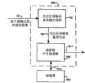
图6说明采用深度图产生逻辑602的设备600的另一实施例,深度图产生逻辑602操作以基于由单个相机16(例如带有具有固定焦距的透镜的单个相机)或任何其它合适单个相机捕获的图像的关注区而产生深度图604。深度图604可存储在存储器608中,存储器608可按需要为高速缓存存储器、帧缓冲器存储器或任何其它合适的存储器。深度图产生逻辑602还提供透镜位置控制信息608以控制相机的透镜位置设定,所述透镜位置控制信息608是基于均匀或不均匀透镜位置数据。透镜控制以如上所述的方式操作,但不同的是例如当均匀的位置数据存储在存储器中时,将此信息用以控制透镜位置且获得所述透镜位置(而非不均匀透镜位置)处的信息的对应帧。由此,深度图产生逻辑602还包含类似于上文关于自动对焦控制操作描述的透镜位置控制信息产生逻辑。还参看图7,深度图产生逻辑602使用例如图像清晰度量度逻辑120确定每一关注区的对焦量度信息133。举例来说,如果将一帧划分为25个区域,将每一区域视为关注区且因此计算25个量度(每一关注区一个)。深度图产生逻辑602基于从所有相关所捕获帧获得的对焦量度信息确定每一关注区的最佳透镜位置以产生深度图604,且由此,深度图是基于来自多个帧的对焦量度信息133。由此,将单个相机用以在不同透镜位置处捕获若干图像,且这些图像中的每一者被划分为若干关注区。随后针对每一帧中的关注区中的每一者产生对焦量度信息,且将来自每一帧的最高量度用以填充深度图604。由此,深度图产生逻辑602提供关注区深度图信息612以填充深度图604。关注区深度图信息可为(例如)基于每关注区的值和/或如下文所述的其它信息。FIG. 6 illustrates another embodiment of a
设备600包含如上所述的含有透镜位置数据的存储器608,且其还包含用以基于所产生深度图来执行图像产生操作的逻辑。举例来说,深度图产生器逻辑189产生图像操作控制信息614,其例如可控制闪光灯操作,使得使用或不使用相机闪光灯来拍摄最终图像(见图4)。作为另一实例,图像产生操作可为由例如视频上部处理器或任何其它合适的颜色处理电路控制颜色处理操作。也可基于深度图信息来控制任何其它合适的图像产生操作。
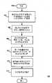
图8说明用以产生深度图604的图像处理方法的一个实例,所述方法在框802中开始,且如框804中所示包含使用单个数码相机捕获对应于基于透镜位置数据的一组透镜位置的一组图像。捕获对应于所述组透镜位置的所述组图像(框804)包含在第一透镜位置捕获图像,从所述组透镜位置选择下一透镜位置,在下一透镜位置处捕获下一图像,以及在额外的接下来的透镜位置处捕获额外的接下来的图像直到所述组为空。如框806中所示,方法包含确定所述组图像中的每一图像的关注区。如上所述,这些操作优选以循序方式完成,其中获得每一帧且产生所述帧的关注区并随后与深度图中的对应关注区的先前量度比较,且将给定关注区的最高量度存储在深度图中。如框808中所示,方法包含确定如上所述的组的每一图像中的关注区中的每一者的对焦量度信息。如框810中陈述,方法包含基于来自所获得的帧的子集或全部所获得的帧的对焦量度信息而确定关注区中的每一者的最佳透镜位置(例如,处于最高量度的透镜位置)。如框812中所示,方法包含基于用以获得所捕获的图像组的最佳透镜位置而产生所述帧的关注区的深度图。如框814中所示,一旦已产生深度图,则其可用以执行图像处理操作,例如启动闪光灯、停用闪光灯、选择最终图像的待使用的颜色增强操作或任何其它合适的图像处理操作。8 illustrates one example of an image processing method to generate a
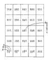
图9说明所产生且用以产生深度图的数据的一个实例。在此实例中,数据包含针对每一ROI的最佳透镜位置。使用此透镜位置信息基于图12所示的数据(所存储)来确定用于深度图的距离。然而将认识到,任何合适的信息可存储在其中。如图示,存在5×5关注区阵列,其均匀地覆盖相机的视场。在此实例中,结果是来自约6米的工作距离。阵列是在透镜位置250处拍摄,且对于每一关注区显示三个数字值。在此实例中,值或量度900表示透镜位置250处的对焦清晰度量度。量度902表示根据所有经评估图像针对关注区实现的最佳/最大对焦量度值,且值904表示对应于最高图像清晰度量度值的最佳透镜位置。使用视场的中心(例如关注区906)对(例如)相机进行对焦以拍摄最终图像。然而,在最终图像期间可使用具有高图像清晰度量度值900的其它关注区而非中心关注区来使相机对焦。此深度图提供粗略深度图,其展示基于中心关注区906的在175处的最佳总体透镜位置和在中心关注区906周围的大部分关注区。产生的深度图604(实例展示于表Ⅱ中)可有效地用于改进各种过程。举例来说,可确定在目标跟踪的情况下,只要目标超过某一距离(例如60cm),则即使目标正在移动靠近或远离相机也无需调整透镜位置。另外,如上所述,也可基于深度图决定是否使用闪光灯。也可按需要基于深度图来修改或利用其它过程。也如框814中所示,方法包含控制透镜以基于其最佳对焦位置而对焦于特定关注区上以进行最终图像捕获。9 illustrates one example of data generated and used to generate a depth map. In this example, the data includes the optimal lens position for each ROI. This lens position information is used to determine distances for the depth map based on the data (stored) shown in FIG. 12 . It will be appreciated, however, that any suitable information may be stored therein. As shown, there is a 5x5 array of regions of interest that evenly covers the camera's field of view. In this example, the results are from a working distance of about 6 meters. The array is taken at
深度图产生是在不使用任何额外传感器(距离传感器、飞行时间传感器、相位检测传感器)、装置(例如,立体相机系统)和结构光(例如,结构化矩形栅格激光)的情况下完成。为了产生深度图,使用透镜位置与物距之间的关系。这可预先针对给定手机相机型号而产生,且可保存作为查找表(LUT)以在相机操作期间使用。图12展示上文详细说明的相机的此关系。图12中所示的点存储在存储器中,且可按需要内插所存储点之间的点。Depth map generation is done without using any additional sensors (distance sensors, time-of-flight sensors, phase detection sensors), devices (eg stereo camera system) and structured light (eg structured rectangular grid laser). To generate the depth map, the relationship between lens position and object distance is used. This can be pre-generated for a given cell phone camera model, and saved as a look-up table (LUT) for use during camera operation. Figure 12 shows this relationship for the cameras detailed above. The points shown in Figure 12 are stored in memory, and points between the stored points can be interpolated as needed.
如下针对给定场景产生深度图产生:A depth map is generated for a given scene as follows:
将相机视场(FOV)划分为一组矩形关注区(ROI):举例来说,8×6个ROI。Divide the camera field of view (FOV) into a set of rectangular regions of interest (ROIs): for example, 8×6 ROIs.
(a)在透镜位置从位置“0”改变为位置“255”(假定总共256个透镜位置)时捕获一组n个图像。可使用8个不均匀(如上文定义)或11个均匀透镜位置。(a) Capture a set of n images as the lens position changes from position "0" to position "255" (assuming a total of 256 lens positions). Either 8 non-uniform (as defined above) or 11 uniform lens positions can be used.
(b)基于每一ROI的所述组n个估计的对焦量度值(对应于n个所捕获图像),确定每一ROI的最佳透镜位置(对应于最佳对焦)。(b) Determining an optimal lens position (corresponding to best focus) for each ROI based on the set of n estimated focus metric values (corresponding to n captured images) for each ROI.
(c)使用透镜位置与物距之间的关系(作为例如LUT而可用),可估计每一ROI的深度(或Z距离)且随后产生总体深度图。(c) Using the relationship between lens position and object distance (available as eg a LUT), the depth (or Z distance) of each ROI can be estimated and then an overall depth map generated.
所产生深度图的精细度或粗糙度水平可取决于以下因素:The level of detail or roughness of the resulting depth map may depend on the following factors:
(a)在相机视场(FOV)内定义的关注区(ROI)的数目:这确定了XY(图像)平面中的深度图分辨率。(a) Number of regions of interest (ROIs) defined within the camera field of view (FOV): This determines the depth map resolution in the XY (image) plane.
(b)所捕获图像的数目(对应于透镜位置的数目):这确定了Z方向上的深度图分辨率(深度/Z距离分辨率)。(b) Number of captured images (corresponding to the number of lens positions): This determines the depth map resolution in the Z direction (depth/Z distance resolution).
下文在表Ⅱ中展示粗略深度图的实例:An example of a coarse depth map is shown below in Table II:
如从此深度图所见,大部分ROI处于约80cm处。更具体来说,相机的视场中的中心区域在约80cm处。As seen from this depth map, most of the ROIs are at about 80 cm. More specifically, the central region in the camera's field of view is at about 80 cm.
在此情况下,由于中心区域相对靠近相机,如下促进了闪光/不闪光选择:应在低照度条件下使用闪光灯。In this case, since the central area is relatively close to the camera, the flash/no-flash selection is facilitated as follows: The flash should be used in low light conditions.
如图9所示,展示每一ROI的最佳透镜位置。将此透镜位置用以基于所存储的图12中的数据点来确定距离。在此实例中,每一关注区的量和大小是预定义的,且此处展示为25的量且每一关注区的大小相同。然而,也可采用不同量和不同大小的区,例如围绕视场中心的较小区和围绕周边的较大区(或反之亦然),或任何其它合适的配置。另外,在此实例中,基于对焦量度信息确定每一关注区的最佳透镜位置包含:确定所捕获图像的每一关注区的对焦量度信息,确定每一关注区和在下一透镜位置处捕获的下一图像的下一对焦量度信息,确定在接下来的透镜位置处的额外接下来的图像中的每一关注区的额外接下来的对焦信息,直到所述组透镜位置为空为止。当这正在发生时,每一后续方法包含将每一关注区和每一所捕获图像的对焦量度信息与先前所捕获关注区和先前所捕获图像进行比较,且将特定关注区的较好或较高量度存储在深度图中。由此,更新深度图的内容以使得较不清晰的关注区的量度被对应关注区的较高清晰度量度替代,直到所述组的所有图像已经评估为止。深度图虽然被展示为包含多片信息,但可仅存储图像的每一关注区的最佳透镜位置之集合。As shown in Figure 9, the optimal lens position for each ROI is shown. This lens position is used to determine the distance based on the stored data points in FIG. 12 . In this example, the amount and size of each region of interest is predefined, and is shown here as an amount of 25 with the same size for each region of interest. However, different amounts and sizes of regions may also be used, such as a smaller region around the center of the field of view and a larger region around the periphery (or vice versa), or any other suitable configuration. Additionally, in this example, determining the optimal lens position for each region of interest based on the focus metric information includes determining focus metric information for each region of interest of the captured image, determining each region of interest and the lens position captured at the next lens position. Next focus metric information for the next image, determining additional next focus information for each region of interest in additional next images at next lens positions until the set of lens positions is empty. While this is happening, each subsequent method includes comparing the focus metric information for each region of interest and each captured image with previously captured regions of interest and previously captured images, and comparing the better or lower High metrics are stored in the depth map. Thereby, the content of the depth map is updated such that the measure of the less sharp region of interest is replaced by the higher clarity measure of the corresponding region of interest until all images of the set have been evaluated. A depth map, although shown as containing pieces of information, may only store a set of optimal lens positions for each region of interest of the image.
图10说明用于使用不均匀透镜位置产生深度图的方法。在此实例中,深度图产生逻辑602通过(例如)经由设备中的可编程寄存器存取预存储的制造数据来辨识相机的特定透镜类型1000。一旦已确定透镜类型,便可使用透镜类型信息从存储器存取特定组的不均匀透镜位置数据。举例来说,可使用查找表来将透镜类型数据转换为透镜位置。Figure 10 illustrates a method for generating a depth map using non-uniform lens positions. In this example, the depth
一旦已识别了特定组的不均匀透镜位置数据,方法就类似于上文关于使用均匀透镜位置信息所描述的那样。举例来说,如步骤1004中所示,方法包含基于不均匀透镜焦点位置数据而将透镜配置或移动到不均匀透镜位置。如步骤1006中所示,随后捕获对应图像,且随后确定图像中的关注区的对焦清晰度信息133,如框806中所示。如框1010中所示,方法包含确定是否已将所有透镜位置用以捕获图像。如果否,那么方法包含如步骤1012中所示将透镜移动到对应于下一透镜位置数据点的下一位置。然而,如果已捕获对应于所述组透镜位置的所有图像,那么方法包含确定所有图像的所有关注区的透镜位置,如框810中所示。这可包含例如在每一相应图像已被捕获之后确定每一图像的每一关注区的清晰度信息,且随后如果已获得与同一关注区相关联的较高量度则重写存储器中的量度(如果在深度图中)。如框812中所示,方法包含如上文所述产生深度图。Once the particular set of non-uniform lens position data has been identified, the method is similar to that described above with respect to using the uniform lens position information. For example, as shown in
图11说明系统1100的一个实例,其包含帧信息传输装置1102(例如设备100)和帧信息接收装置1104。传输装置可为例如相机手机或任何其它合适装置,且接收装置1104可为另一相机手机、数字电视、桌上型计算机、膝上型计算机或任何其它合适装置。在此实例中,传输装置(也可为接收装置)使用例如JPEG编码逻辑148(见图4)用例如JPEG压缩算法或任何其它合适压缩算法(例如用于动画的MPEG)来压缩最终帧或其部分。随后传输所存储的深度图604(即,表示表Ⅱ中的数据的数据)和经编码帧198以传达至接收装置1104。这可包含(例如)通过例如因特网的网络或以任何合适方式无线地传达信息。另外,经压缩的帧信息可为经压缩的完整帧,或帧的经压缩行,或多个帧的信息或任何其它合适的经压缩帧信息。通过使用高得多数目的ROI和高得多数目的透镜位置,可沿着所有三个XYZ轴以高得多的分辨率创建深度图。这可用以产生3D图像数据。深度图数据可附加到经压缩或未经压缩的2D图像数据且随后可一起传输。FIG. 11 illustrates one example of a
接收装置1104包含对应的解压缩器1106、3D图像产生器1108和(如果需要)显示器1110。在操作中,接收装置接收经压缩帧信息198和对应深度图604,且使用对应解压缩算法(对应于用以压缩信息的压缩算法)解压缩经压缩的帧信息198。经解压缩的帧信息1112随后连同深度图信息604一起被提供到3D图像产生器,例如3D图形处理器或任何其它合适结构。如虚线箭头1114所示,深度图也可被压缩且随后被解压缩以供3D图像产生器1108使用。3D图像产生器可随后使用解压缩的帧信息和深度图信息,以便基于此信息产生3D图像。深度图604是如上所述的基于单个相机的深度图604,其中利用单个相机来基于如上所述的均匀或不均匀透镜位置拍摄帧序列。The
已仅为了说明和描述而不是限制的目的呈现了上文对本文描述的本发明和实例的详细描述。因此预期本发明涵盖属于上文揭示和本文主张的根本原理的精神和范围内的任何和所有修改、变化或均等物。The foregoing detailed description of the invention and examples described herein have been presented for purposes of illustration and description only and not limitation. The invention is therefore intended to cover any and all modifications, variations or equivalents which fall within the spirit and scope of the underlying principles disclosed above and claimed herein.
Claims (19)
Applications Claiming Priority (3)
| Application Number | Priority Date | Filing Date | Title |
|---|---|---|---|
| US11/964,992 | 2007-12-27 | ||
| US11/964,992US8233077B2 (en) | 2007-12-27 | 2007-12-27 | Method and apparatus with depth map generation |
| PCT/CA2008/002298WO2009082822A1 (en) | 2007-12-27 | 2008-12-29 | Method and apparatus with depth map generation |
Publications (2)
| Publication Number | Publication Date |
|---|---|
| CN101918893A CN101918893A (en) | 2010-12-15 |
| CN101918893Btrue CN101918893B (en) | 2012-07-18 |
Family
ID=40797773
Family Applications (1)
| Application Number | Title | Priority Date | Filing Date |
|---|---|---|---|
| CN2008801227570AActiveCN101918893B (en) | 2007-12-27 | 2008-12-29 | Method and apparatus with depth map generation |
Country Status (6)
| Country | Link |
|---|---|
| US (1) | US8233077B2 (en) |
| EP (2) | EP2934000B1 (en) |
| JP (1) | JP5226805B2 (en) |
| KR (3) | KR20140072114A (en) |
| CN (1) | CN101918893B (en) |
| WO (1) | WO2009082822A1 (en) |
Families Citing this family (87)
| Publication number | Priority date | Publication date | Assignee | Title |
|---|---|---|---|---|
| US8154647B2 (en)* | 2008-03-05 | 2012-04-10 | Applied Minds, Llc | Automated extended depth of field imaging apparatus and method |
| US11792538B2 (en) | 2008-05-20 | 2023-10-17 | Adeia Imaging Llc | Capturing and processing of images including occlusions focused on an image sensor by a lens stack array |
| US8866920B2 (en) | 2008-05-20 | 2014-10-21 | Pelican Imaging Corporation | Capturing and processing of images using monolithic camera array with heterogeneous imagers |
| KR101206895B1 (en)* | 2008-12-22 | 2012-11-30 | 한국전자통신연구원 | Rendering system and data processing method using of rendering system |
| TW201101799A (en)* | 2009-06-17 | 2011-01-01 | Altek Corp | Digital image sharpening treatment method and its system thereof |
| US20110025830A1 (en)* | 2009-07-31 | 2011-02-03 | 3Dmedia Corporation | Methods, systems, and computer-readable storage media for generating stereoscopic content via depth map creation |
| EP2502115A4 (en) | 2009-11-20 | 2013-11-06 | Pelican Imaging Corp | CAPTURE AND IMAGE PROCESSING USING A MONOLITHIC CAMERAS NETWORK EQUIPPED WITH HETEROGENEOUS IMAGERS |
| JP2011147067A (en)* | 2010-01-18 | 2011-07-28 | Sony Corp | Image processing apparatus and method, and program |
| JP5660361B2 (en)* | 2010-03-26 | 2015-01-28 | ソニー株式会社 | Image processing apparatus and method, and program |
| CN102438153B (en)* | 2010-09-29 | 2015-11-25 | 华为终端有限公司 | Multi-camera image correction method and equipment |
| US9025019B2 (en) | 2010-10-18 | 2015-05-05 | Rockwell Automation Technologies, Inc. | Time of flight (TOF) sensors as replacement for standard photoelectric sensors |
| TW201219740A (en)* | 2010-11-04 | 2012-05-16 | Quanta Comp Inc | Method and apparatus for measuring Depth of Field |
| JP5870264B2 (en)* | 2010-11-08 | 2016-02-24 | パナソニックIpマネジメント株式会社 | Imaging apparatus, imaging method, program, and integrated circuit |
| CN102486603A (en)* | 2010-12-01 | 2012-06-06 | 广达电脑股份有限公司 | Depth of field measuring device and method for measuring depth of field |
| US8878950B2 (en) | 2010-12-14 | 2014-11-04 | Pelican Imaging Corporation | Systems and methods for synthesizing high resolution images using super-resolution processes |
| US9307134B2 (en)* | 2011-03-25 | 2016-04-05 | Sony Corporation | Automatic setting of zoom, aperture and shutter speed based on scene depth map |
| AU2011224051B2 (en)* | 2011-09-14 | 2014-05-01 | Canon Kabushiki Kaisha | Determining a depth map from images of a scene |
| CN104081414B (en) | 2011-09-28 | 2017-08-01 | Fotonation开曼有限公司 | Systems and methods for encoding and decoding light field image files |
| JP5953187B2 (en)* | 2011-10-11 | 2016-07-20 | オリンパス株式会社 | Focus control device, endoscope system, and focus control method |
| WO2013058735A1 (en) | 2011-10-18 | 2013-04-25 | Hewlett-Packard Development Company, L.P. | Depth mask assisted video stabilization |
| US8660362B2 (en) | 2011-11-21 | 2014-02-25 | Microsoft Corporation | Combined depth filtering and super resolution |
| US9161010B2 (en)* | 2011-12-01 | 2015-10-13 | Sony Corporation | System and method for generating robust depth maps utilizing a multi-resolution procedure |
| FR2985140B1 (en)* | 2011-12-22 | 2014-08-29 | Commissariat Energie Atomique | INTEGRATED THREE-DIMENSIONAL VISION SENSOR |
| US9473702B2 (en) | 2011-12-23 | 2016-10-18 | Nokia Technologies Oy | Controlling image capture and/or controlling image processing |
| KR20130102400A (en)* | 2012-03-07 | 2013-09-17 | 삼성전자주식회사 | Time of flight sensor and time of flight camera |
| JP6063634B2 (en)* | 2012-03-29 | 2017-01-18 | オリンパス株式会社 | Focus adjustment device |
| US9857919B2 (en)* | 2012-05-17 | 2018-01-02 | Hong Kong Applied Science And Technology Research | Wearable device with intelligent user-input interface |
| US20140002674A1 (en) | 2012-06-30 | 2014-01-02 | Pelican Imaging Corporation | Systems and Methods for Manufacturing Camera Modules Using Active Alignment of Lens Stack Arrays and Sensors |
| EP2698979B1 (en)* | 2012-08-16 | 2017-05-03 | Wincor Nixdorf International GmbH | Method and device for presenting objects |
| PL4296963T3 (en) | 2012-08-21 | 2025-04-28 | Adeia Imaging Llc | Method for depth detection in images captured using array cameras |
| CN103634588A (en)* | 2012-08-27 | 2014-03-12 | 联想(北京)有限公司 | Image composition method and electronic apparatus |
| TWI494792B (en)* | 2012-09-07 | 2015-08-01 | Pixart Imaging Inc | Gesture recognition system and method |
| FR2996925B1 (en) | 2012-10-17 | 2017-06-16 | Office Nat D Etudes Et De Rech Aerospatiales | METHOD FOR DESIGNING A PASSIVE MONOVOIE IMAGER CAPABLE OF ESTIMATING DEPTH |
| US8866912B2 (en) | 2013-03-10 | 2014-10-21 | Pelican Imaging Corporation | System and methods for calibration of an array camera using a single captured image |
| US9134114B2 (en) | 2013-03-11 | 2015-09-15 | Texas Instruments Incorporated | Time of flight sensor binning |
| US8908063B2 (en)* | 2013-03-11 | 2014-12-09 | Texas Instruments Incorporated | Method and apparatus for a time-of-flight sensor with charge storage |
| US9633442B2 (en) | 2013-03-15 | 2017-04-25 | Fotonation Cayman Limited | Array cameras including an array camera module augmented with a separate camera |
| US9497429B2 (en) | 2013-03-15 | 2016-11-15 | Pelican Imaging Corporation | Extended color processing on pelican array cameras |
| US9438888B2 (en) | 2013-03-15 | 2016-09-06 | Pelican Imaging Corporation | Systems and methods for stereo imaging with camera arrays |
| US10122993B2 (en) | 2013-03-15 | 2018-11-06 | Fotonation Limited | Autofocus system for a conventional camera that uses depth information from an array camera |
| US20140358298A1 (en)* | 2013-05-31 | 2014-12-04 | DWFritz Automation, Inc. | Alignment tool |
| KR102124601B1 (en) | 2013-06-21 | 2020-06-19 | 삼성전자주식회사 | Apparatas and method for displaying an information of extracting a subject distance in an electronic device |
| US9847082B2 (en)* | 2013-08-23 | 2017-12-19 | Honeywell International Inc. | System for modifying speech recognition and beamforming using a depth image |
| US9973677B2 (en)* | 2013-10-14 | 2018-05-15 | Qualcomm Incorporated | Refocusable images |
| WO2015081279A1 (en) | 2013-11-26 | 2015-06-04 | Pelican Imaging Corporation | Array camera configurations incorporating multiple constituent array cameras |
| KR102149463B1 (en)* | 2014-02-19 | 2020-08-28 | 삼성전자주식회사 | Electronic device and method for processing image |
| US9418432B2 (en) | 2014-03-28 | 2016-08-16 | Sony Corporation | Imaging system with depth estimation mechanism and method of operation thereof |
| CA2848794C (en)* | 2014-04-11 | 2016-05-24 | Blackberry Limited | Building a depth map using movement of one camera |
| WO2015183824A1 (en)* | 2014-05-26 | 2015-12-03 | Pelican Imaging Corporation | Autofocus system for a conventional camera that uses depth information from an array camera |
| JP2017531976A (en) | 2014-09-29 | 2017-10-26 | フォトネイション ケイマン リミテッド | System and method for dynamically calibrating an array camera |
| US9292926B1 (en)* | 2014-11-24 | 2016-03-22 | Adobe Systems Incorporated | Depth map generation |
| US9824427B2 (en)* | 2015-04-15 | 2017-11-21 | Light Labs Inc. | Methods and apparatus for generating a sharp image |
| CN107851322B (en)* | 2015-07-13 | 2022-04-19 | 皇家飞利浦有限公司 | Method and apparatus for determining a depth map for an image |
| CN106610553B (en)* | 2015-10-22 | 2019-06-18 | 深圳超多维科技有限公司 | A kind of method and device of auto-focusing |
| DE102016200660A1 (en)* | 2015-12-23 | 2017-06-29 | Robert Bosch Gmbh | Method of creating a depth map by means of a camera |
| EP3185209B1 (en)* | 2015-12-23 | 2019-02-27 | STMicroelectronics (Research & Development) Limited | Depth maps generated from a single sensor |
| US10229502B2 (en)* | 2016-02-03 | 2019-03-12 | Microsoft Technology Licensing, Llc | Temporal time-of-flight |
| WO2017143427A1 (en)* | 2016-02-25 | 2017-08-31 | Synaptive Medical (Barbados) Inc. | System and method for scope based depth map acquisition |
| CN106060521B (en)* | 2016-06-21 | 2019-04-16 | 英华达(上海)科技有限公司 | Depth image constructing method and system |
| US10277889B2 (en) | 2016-12-27 | 2019-04-30 | Qualcomm Incorporated | Method and system for depth estimation based upon object magnification |
| JP6838994B2 (en)* | 2017-02-22 | 2021-03-03 | キヤノン株式会社 | Imaging device, control method and program of imaging device |
| FR3074385B1 (en) | 2017-11-28 | 2020-07-03 | Stmicroelectronics (Crolles 2) Sas | SWITCHES AND PHOTONIC INTERCONNECTION NETWORK INTEGRATED IN AN OPTOELECTRONIC CHIP |
| US10529084B2 (en)* | 2018-02-06 | 2020-01-07 | Htc Corporation | Image processing method, electronic device, and non-transitory computer readable storage medium |
| US10582111B2 (en)* | 2018-03-30 | 2020-03-03 | Qualcomm Incorporated | Systems and methods for autofocus and depth map generation |
| US10609274B2 (en) | 2018-03-30 | 2020-03-31 | Qualcomm Incorporated | Systems and methods for autofocus and depth map generation |
| US11682107B2 (en)* | 2018-12-14 | 2023-06-20 | Sony Corporation | Depth of field adjustment in images based on time of flight depth maps |
| CN114365475B (en)* | 2019-07-18 | 2024-03-01 | 高途乐公司 | Camera with reconfigurable lens assembly |
| US11270110B2 (en) | 2019-09-17 | 2022-03-08 | Boston Polarimetrics, Inc. | Systems and methods for surface modeling using polarization cues |
| WO2021071992A1 (en) | 2019-10-07 | 2021-04-15 | Boston Polarimetrics, Inc. | Systems and methods for augmentation of sensor systems and imaging systems with polarization |
| WO2021107384A1 (en)* | 2019-11-29 | 2021-06-03 | Samsung Electronics Co., Ltd. | Generation of bokeh images using adaptive focus range and layered scattering |
| US11094041B2 (en) | 2019-11-29 | 2021-08-17 | Samsung Electronics Co., Ltd. | Generation of bokeh images using adaptive focus range and layered scattering |
| DE112020005932T5 (en) | 2019-11-30 | 2023-01-05 | Boston Polarimetrics, Inc. | SYSTEMS AND METHODS FOR SEGMENTATION OF TRANSPARENT OBJECTS USING POLARIZATION CHARACTERISTICS |
| EP4081933A4 (en) | 2020-01-29 | 2024-03-20 | Intrinsic Innovation LLC | Systems and methods for characterizing object pose detection and measurement systems |
| US11797863B2 (en) | 2020-01-30 | 2023-10-24 | Intrinsic Innovation Llc | Systems and methods for synthesizing data for training statistical models on different imaging modalities including polarized images |
| US11953700B2 (en) | 2020-05-27 | 2024-04-09 | Intrinsic Innovation Llc | Multi-aperture polarization optical systems using beam splitters |
| GB202015901D0 (en)* | 2020-10-07 | 2020-11-18 | Ash Tech Limited | System and method for digital image processing |
| US11657529B2 (en)* | 2020-10-12 | 2023-05-23 | Black Sesame Technologies Inc. | Multiple camera system with flash for depth map generation |
| US12069227B2 (en) | 2021-03-10 | 2024-08-20 | Intrinsic Innovation Llc | Multi-modal and multi-spectral stereo camera arrays |
| US12020455B2 (en) | 2021-03-10 | 2024-06-25 | Intrinsic Innovation Llc | Systems and methods for high dynamic range image reconstruction |
| US11290658B1 (en) | 2021-04-15 | 2022-03-29 | Boston Polarimetrics, Inc. | Systems and methods for camera exposure control |
| US11954886B2 (en) | 2021-04-15 | 2024-04-09 | Intrinsic Innovation Llc | Systems and methods for six-degree of freedom pose estimation of deformable objects |
| US12067746B2 (en) | 2021-05-07 | 2024-08-20 | Intrinsic Innovation Llc | Systems and methods for using computer vision to pick up small objects |
| US12175741B2 (en) | 2021-06-22 | 2024-12-24 | Intrinsic Innovation Llc | Systems and methods for a vision guided end effector |
| US12340538B2 (en) | 2021-06-25 | 2025-06-24 | Intrinsic Innovation Llc | Systems and methods for generating and using visual datasets for training computer vision models |
| US12172310B2 (en) | 2021-06-29 | 2024-12-24 | Intrinsic Innovation Llc | Systems and methods for picking objects using 3-D geometry and segmentation |
| US11689813B2 (en) | 2021-07-01 | 2023-06-27 | Intrinsic Innovation Llc | Systems and methods for high dynamic range imaging using crossed polarizers |
| US12293535B2 (en) | 2021-08-03 | 2025-05-06 | Intrinsic Innovation Llc | Systems and methods for training pose estimators in computer vision |
Citations (8)
| Publication number | Priority date | Publication date | Assignee | Title |
|---|---|---|---|---|
| US5305092A (en)* | 1991-09-03 | 1994-04-19 | Hitachi, Ltd. | Apparatus for obtaining three-dimensional volume data of an object |
| US5793900A (en)* | 1995-12-29 | 1998-08-11 | Stanford University | Generating categorical depth maps using passive defocus sensing |
| US6128071A (en)* | 1998-06-04 | 2000-10-03 | Canon Kabushiki Kaisha | Range data recordation |
| US20020110273A1 (en)* | 1997-07-29 | 2002-08-15 | U.S. Philips Corporation | Method of reconstruction of tridimensional scenes and corresponding reconstruction device and decoding system |
| US20070018977A1 (en)* | 2005-07-25 | 2007-01-25 | Wolfgang Niem | Method and apparatus for generating a depth map |
| US20070053675A1 (en)* | 2005-09-08 | 2007-03-08 | Pollard Stephen B | Image data processing method and apparatus |
| CN101071251A (en)* | 2006-05-11 | 2007-11-14 | 致伸科技股份有限公司 | Evaluating methods for autofocusing on least effective sample points |
| US20090167930A1 (en)* | 2007-12-27 | 2009-07-02 | Ati Technologies Ulc | Method and apparatus with fast camera auto focus |
Family Cites Families (13)
| Publication number | Priority date | Publication date | Assignee | Title |
|---|---|---|---|---|
| JP3851027B2 (en) | 1999-08-27 | 2006-11-29 | 株式会社リコー | Autofocus device and camera |
| JP2001257932A (en) | 2000-03-09 | 2001-09-21 | Denso Corp | Image pickup device |
| US7106366B2 (en) | 2001-12-19 | 2006-09-12 | Eastman Kodak Company | Image capture system incorporating metadata to facilitate transcoding |
| AU2003274951A1 (en) | 2002-08-30 | 2004-03-19 | Orasee Corp. | Multi-dimensional image system for digital image input and output |
| JP2004317699A (en) | 2003-04-15 | 2004-11-11 | Nikon Gijutsu Kobo:Kk | Digital camera |
| JP3927934B2 (en)* | 2003-09-02 | 2007-06-13 | キヤノン株式会社 | Imaging device and focus control method of imaging device |
| JP4496463B2 (en)* | 2004-03-29 | 2010-07-07 | ソニー株式会社 | Imaging apparatus and method, recording medium, and program |
| JP2006058572A (en)* | 2004-08-19 | 2006-03-02 | Fujitsu Ltd | Electronic device, shooting mode switching method, and shooting mode switching software program |
| JP2006119550A (en)* | 2004-10-25 | 2006-05-11 | Canon Inc | Automatic focusing device and imaging device |
| FR2887347B1 (en) | 2005-06-17 | 2007-09-21 | Canon Res Ct France Soc Par Ac | METHOD AND DEVICE FOR CONSTRUCTING A DEPTH CARD OF A DIGITAL IMAGE |
| US7821570B2 (en)* | 2005-11-30 | 2010-10-26 | Eastman Kodak Company | Adjusting digital image exposure and tone scale |
| TWI314832B (en)* | 2006-10-03 | 2009-09-11 | Univ Nat Taiwan | Single lens auto focus system for stereo image generation and method thereof |
| US8077964B2 (en)* | 2007-03-19 | 2011-12-13 | Sony Corporation | Two dimensional/three dimensional digital information acquisition and display device |
- 2007
- 2007-12-27USUS11/964,992patent/US8233077B2/ennot_activeExpired - Fee Related
- 2008
- 2008-12-29KRKR1020147010550Apatent/KR20140072114A/ennot_activeCeased
- 2008-12-29KRKR1020107016674Apatent/KR101554639B1/ennot_activeExpired - Fee Related
- 2008-12-29JPJP2010539980Apatent/JP5226805B2/ennot_activeExpired - Fee Related
- 2008-12-29WOPCT/CA2008/002298patent/WO2009082822A1/enactiveApplication Filing
- 2008-12-29KRKR1020127022550Apatent/KR20120119920A/ennot_activeCeased
- 2008-12-29EPEP15170358.4Apatent/EP2934000B1/enactiveActive
- 2008-12-29EPEP08867017Apatent/EP2238507A4/ennot_activeCeased
- 2008-12-29CNCN2008801227570Apatent/CN101918893B/enactiveActive
Patent Citations (8)
| Publication number | Priority date | Publication date | Assignee | Title |
|---|---|---|---|---|
| US5305092A (en)* | 1991-09-03 | 1994-04-19 | Hitachi, Ltd. | Apparatus for obtaining three-dimensional volume data of an object |
| US5793900A (en)* | 1995-12-29 | 1998-08-11 | Stanford University | Generating categorical depth maps using passive defocus sensing |
| US20020110273A1 (en)* | 1997-07-29 | 2002-08-15 | U.S. Philips Corporation | Method of reconstruction of tridimensional scenes and corresponding reconstruction device and decoding system |
| US6128071A (en)* | 1998-06-04 | 2000-10-03 | Canon Kabushiki Kaisha | Range data recordation |
| US20070018977A1 (en)* | 2005-07-25 | 2007-01-25 | Wolfgang Niem | Method and apparatus for generating a depth map |
| US20070053675A1 (en)* | 2005-09-08 | 2007-03-08 | Pollard Stephen B | Image data processing method and apparatus |
| CN101071251A (en)* | 2006-05-11 | 2007-11-14 | 致伸科技股份有限公司 | Evaluating methods for autofocusing on least effective sample points |
| US20090167930A1 (en)* | 2007-12-27 | 2009-07-02 | Ati Technologies Ulc | Method and apparatus with fast camera auto focus |
Also Published As
| Publication number | Publication date |
|---|---|
| KR20140072114A (en) | 2014-06-12 |
| KR101554639B1 (en) | 2015-09-21 |
| EP2238507A1 (en) | 2010-10-13 |
| KR20120119920A (en) | 2012-10-31 |
| KR20100102186A (en) | 2010-09-20 |
| EP2238507A4 (en) | 2011-04-20 |
| WO2009082822A1 (en) | 2009-07-09 |
| US20090167923A1 (en) | 2009-07-02 |
| JP5226805B2 (en) | 2013-07-03 |
| EP2934000A1 (en) | 2015-10-21 |
| CN101918893A (en) | 2010-12-15 |
| JP2011508268A (en) | 2011-03-10 |
| US8233077B2 (en) | 2012-07-31 |
| EP2934000B1 (en) | 2017-11-15 |
Similar Documents
| Publication | Publication Date | Title |
|---|---|---|
| CN101918893B (en) | Method and apparatus with depth map generation | |
| US8724013B2 (en) | Method and apparatus with fast camera auto focus | |
| JP2011508268A5 (en) | ||
| CN109547701B (en) | Image capturing method, device, storage medium and electronic device | |
| EP3435655B1 (en) | Electronic device for acquiring image using plurality of cameras and method for processing image using the same | |
| US10810720B2 (en) | Optical imaging method and apparatus | |
| CN112840634B (en) | Electronic device and method for obtaining image | |
| JP5453573B2 (en) | Imaging apparatus, imaging method, and program | |
| CN113888452A (en) | Image fusion method, electronic device, storage medium and computer program product | |
| CN106612392A (en) | Image shooting method and device based on double cameras | |
| CN106170064A (en) | Camera focusing method, system and electronic equipment | |
| CN105744151A (en) | Method Of Face Detection, Method Of Image Processing, Face Detection Device And Electronic System Including The Same | |
| CN116156321B (en) | A focusing method, device, equipment and storage medium | |
| CN115516494A (en) | Method for generating an image and electronic device thereof | |
| US9179060B2 (en) | Method and apparatus for camera shake effect image stabilization | |
| CN114286011B (en) | Focusing method and device | |
| CN112367465B (en) | Image output method, device and electronic equipment | |
| CN112565605B (en) | Image display method, device and electronic device | |
| KR20200110906A (en) | Electronic device for auto focusing function and operating method thereof | |
| CN106657600B (en) | Image processing method and mobile terminal | |
| CN112584015A (en) | Object detection method, device, storage medium and electronic equipment | |
| CN115037867A (en) | Shooting method, device, computer-readable storage medium, and electronic device | |
| CN116017105B (en) | Shooting method, shooting device, electronic equipment and storage medium | |
| CN112637504B (en) | Focusing method and device | |
| KR20200036264A (en) | Method and electronic device for auto focusing |
Legal Events
| Date | Code | Title | Description |
|---|---|---|---|
| C06 | Publication | ||
| PB01 | Publication | ||
| C10 | Entry into substantive examination | ||
| SE01 | Entry into force of request for substantive examination | ||
| C14 | Grant of patent or utility model | ||
| GR01 | Patent grant |