CN101912300B - Minimally invasive pedicle screw fixation for thoracolumbar fractures - Google Patents
Minimally invasive pedicle screw fixation for thoracolumbar fracturesDownload PDFInfo
- Publication number
- CN101912300B CN101912300BCN2010102713109ACN201010271310ACN101912300BCN 101912300 BCN101912300 BCN 101912300BCN 2010102713109 ACN2010102713109 ACN 2010102713109ACN 201010271310 ACN201010271310 ACN 201010271310ACN 101912300 BCN101912300 BCN 101912300B
- Authority
- CN
- China
- Prior art keywords
- screw
- rod
- handle
- sleeve
- head
- Prior art date
- Legal status (The legal status is an assumption and is not a legal conclusion. Google has not performed a legal analysis and makes no representation as to the accuracy of the status listed.)
- Expired - Fee Related
Links
Images


Landscapes
- Surgical Instruments (AREA)
- Prostheses (AREA)
Abstract
Description
Translated fromChinese技术领域technical field
本发明涉及是医疗器械,更详细地讲是关于骨科手术器械,用于治疗胸腰椎等骨折复位手术的微创胸腰椎骨折椎弓根钉固定多节段置钉器械。The present invention relates to a medical device, in particular to an orthopedic surgical device, a minimally invasive thoracolumbar fracture pedicle screw fixation multi-segment screw placement device used for thoracolumbar fracture reduction surgery.
背景技术Background technique
胸腰椎骨折是常见的脊柱骨折,传统的手术是将骨折部位用椎弓根螺钉来复位固定,椎弓根螺钉因具有三柱固定的优势,被推广应用,但其手术方式是采用开背置入椎弓根螺钉,它是在人体后背正中切口切开,沿切口向两侧剥离,创伤大、出血多、住院时间长,增加了患者的病痛和经济负担;手术中需扩展剥离椎旁肌,容易导致椎旁肌丧失神经支配,造成晚期功能障碍,常患有后腰背疼痛、僵硬等并发症。在临床中,现有的椎弓根螺钉器械仅为传统开放手术所设计和使用的,手术麻烦、创口大、患者痛苦大,在经皮穿刺置入椎弓根螺钉手术中,对于螺钉的置入和纵棒的导入过程难度很大,因此不能用于多节段固定胸腰椎骨折。对于一些特殊后路椎弓根螺钉系统,则需特殊匹配的椎弓根螺钉,造价较高,大大增加患者负担。目前迫切需要研制一种专门用于经皮置入椎弓根螺钉的微创器械,既可使用普通椎弓根螺钉固定,又适用万向椎弓根螺钉等特殊螺钉,同时能够实现多节段椎体固定来满足临床的实际需求,以减轻患者负担、增加社会和经济效益。Thoracolumbar fractures are common spinal fractures. The traditional operation is to fix the fracture site with pedicle screws. Pedicle screws are widely used because of their advantages of three-column fixation. For pedicle screw insertion, it is cut in the middle of the back of the human body and stripped to both sides along the incision. The trauma is large, the bleeding is heavy, and the hospital stay is long, which increases the patient's pain and financial burden; the operation needs to be extended and stripped. Muscles can easily lead to the loss of innervation of the paraspinal muscles, resulting in late dysfunction, and often suffer from complications such as back pain and stiffness. In clinical practice, the existing pedicle screw instruments are only designed and used in traditional open surgery. The operation is troublesome, the wound is large, and the patient suffers a lot. It is very difficult to introduce the insertion and longitudinal rods, so it cannot be used for multi-segment fixation of thoracolumbar fractures. For some special posterior pedicle screw systems, special matching pedicle screws are required, which is expensive and greatly increases the burden on patients. At present, there is an urgent need to develop a minimally invasive device specially used for percutaneous placement of pedicle screws, which can be fixed with ordinary pedicle screws and special screws such as universal pedicle screws. Vertebral body fixation to meet the actual clinical needs, to reduce the burden on patients, increase social and economic benefits.
发明内容Contents of the invention
本发明的目的在于提供一种能够消除上述缺点,具有结构合理、手术简单、操作方便、定位准确、置钉稳固、疗效好、成本低、患者痛苦轻、经济负担小、可多钉置入一次性固定等特点的微创胸腰椎骨折椎弓根钉固定多节段置钉器械。尤其是采用胸腰椎骨折后路经皮置植入椎弓根螺钉固定技术,研发出了凿孔置针逐级扩大、外调式置入椎弓根螺钉方向等配套微创器械,实现了普通椎弓根螺钉对多节段椎体固定技术,以方便骨折手术中的螺钉置入,提高螺钉置入的准确度,减少了创伤面小和手术时间,改善手术方法和治疗效果。攻克了开放手术置入椎弓根螺钉的难关,减少医源性损伤,方便手术中的植骨和内固定物的放置,同时简化手术操作,减少手术创伤,节省手术时间和人力,是理想的治疗胸腰椎骨折专用的手术配套器械。The purpose of the present invention is to provide a device that can eliminate the above disadvantages, has the advantages of reasonable structure, simple operation, convenient operation, accurate positioning, stable nail placement, good curative effect, low cost, light patient pain, small economic burden, and multiple nails can be inserted once. Minimally invasive pedicle screw fixation for thoracolumbar fractures with the characteristics of permanent fixation and other features. In particular, the technique of percutaneous implantation of pedicle screws for thoracolumbar fractures has been adopted, and supporting minimally invasive instruments have been developed, such as step-by-step expansion of drilling holes and placement of pedicle screws in externally adjusted directions, realizing the realization of common pedicle screw fixation. The multi-segment vertebral body fixation technology with pedicle screws facilitates screw placement in fracture surgery, improves the accuracy of screw placement, reduces the small trauma area and operation time, and improves surgical methods and treatment effects. It overcomes the difficulty of placing pedicle screws in open surgery, reduces iatrogenic damage, facilitates the placement of bone grafts and internal fixation during surgery, simplifies surgical operations, reduces surgical trauma, and saves surgical time and manpower. It is ideal. Surgical accessories for the treatment of thoracolumbar fractures.
本发明的微创胸腰椎骨折椎弓根钉固定多节段置钉器械主要包括逐级扩张套筒、螺钉导向外套筒、螺钉置入器、联结棒、压力植骨器、空心丝攻、螺钉开口器、螺钉、撑开钳;其中:逐级扩张套筒是由逐级套筒、旋转手柄、穿针孔组成,该逐级套筒是由一组内外套筒构成,即至少由两层以上直径不同、内外逐级相套的圆管所组成;螺钉导向外套筒是由一对对称、匹配扣合的圆套筒、套筒手柄、棒销组成;螺钉置入器是由套筒、手柄、拉杆、塞头、连接柄、旋棒、外套管构成;联结棒是由连接凸头、连接平头、连接棒体连接为一体所构成;压力植骨器是由植骨筒、内顶芯、加压柄、固定外筒所组成,呈枪式结构,在加压柄上装有固定外筒,固定外筒与植骨筒、内顶芯依次活动连接;螺钉是由钉杆、钉尖部、钉尾部构成,钉杆的两端分别与钉尖部、钉尾部连接;螺钉开口器是由扩孔锥杆、扩孔锥头、第二手柄构成,扩孔锥杆的两端分别连接着第二手柄和扩孔锥头;空心丝攻是由丝攻杆、丝攻头、第三手柄构成,丝攻杆的两端分别连接丝攻头和第三手柄;撑开钳是由左、右钳片、调节螺母、调节螺杆、柱销、活动插销所构成,其中,左、右钳片以活动插销为支点。所述的圆套筒是由空芯半圆柱体和锥头构成,在半圆柱体上端安装有套筒手柄,两半圆柱体对接组合成一圆套筒,在半圆柱体上端的套筒手柄上下插接棒销固定组合成一双套筒手柄。所述的拉杆为空芯杆,手柄和塞头分别连接在拉杆的两端,手柄可与拉杆活动或固定连接,塞头与拉杆固定连接,塞头直接塞在螺钉钉尾部的凹槽内。所述的连接凸头是在连接棒体的上端轴向凸起,可与螺钉置入器旋转手柄上的凹槽匹配连接,通过螺钉置入器调节椎弓根螺钉的方向和位置;连接棒下端为连接平头,可与螺钉导向外套筒上端凹槽匹配连接,用于螺钉导向外套筒与螺钉置入器连接。所述的螺钉是指椎弓根螺钉,是由钉杆、钉尖部、钉尾部构成,钉杆的两端分别与钉尖部、钉尾部连接,其中,钉杆上带有螺纹,钉尖部留有凸尖,钉尾部带有内螺纹的凹槽,该凹槽可塞入螺钉置入器的塞头或贯穿螺钉纵连杆,调节螺钉的方向和定位,螺钉准确定位并置入。所述的加压柄是由顶杆、手枪拨柄、枪托构成,在枪托内安装有手枪拨柄,手枪拨柄顶在顶杆的齿道上,手枪拨柄沿着顶杆的齿道前后移动推动顶杆顶住内顶芯与植骨筒相套或退出,内顶芯可将植骨筒中的植骨材料压力顶出。所述的扩孔锥头是由带微齿的钻头,用于钻开骨质点,空心丝攻准确钻出螺纹;第二手柄与扩孔锥杆可活动或固定连接,扩孔锥杆为空芯杆。所述的丝攻杆外带有螺纹齿道,丝攻杆为空芯杆,丝攻杆与丝攻头连为一体,丝攻头呈钻头状,第三手柄与丝攻杆可活动或固定连接。所述的左、右钳片是在两钳头上均留有半圆缺口。上述器械是由医用高分子材料或医用金属材料制成。The minimally invasive thoracolumbar fracture pedicle screw fixation device of the present invention mainly includes a step-by-step expansion sleeve, a screw guide outer sleeve, a screw inserter, a coupling rod, a pressure bone grafting device, a hollow wire tap, Screw opener, screw, spreading pliers; wherein: the step-by-step expansion sleeve is composed of a step-by-step sleeve, a rotating handle, and a needle hole. The step-by-step sleeve is composed of a set of inner and outer sleeves, that is, at least two It is composed of circular tubes with different diameters above the first layer, and the inside and outside are set step by step; the screw guide outer sleeve is composed of a pair of symmetrical, matching and fastening circular sleeves, sleeve handles, and rod pins; the screw inserter is composed of a sleeve tube, handle, pull rod, plug, connecting handle, rotating rod, and outer casing; the connecting rod is composed of connecting convex head, connecting flat head, and connecting rod body; the pressure bone grafting device is composed of a bone grafting cylinder, an inner The top core, the pressure handle and the fixed outer cylinder are composed of a gun-type structure. The fixed outer cylinder is installed on the pressure handle, and the fixed outer cylinder is connected with the bone graft cylinder and the inner top core in sequence; the screw is composed of a nail rod, a nail The two ends of the screw rod are respectively connected with the nail tip and the nail tail; the screw opener is composed of a reaming cone rod, a reaming cone head and a second handle, and the two ends of the reaming cone rod are respectively It is connected with the second handle and the reaming cone head; the hollow tap is composed of a tap rod, a tap head and a third handle, and the two ends of the tap rod are respectively connected with the tap head and the third handle; the spreading pliers are made of The left and right pliers pieces, adjusting nuts, adjusting screw rods, column pins, and movable bolts are formed, wherein the left and right pliers pieces take the movable bolts as fulcrums. The circular sleeve is composed of a hollow half cylinder and a conical head. A sleeve handle is installed on the upper end of the half cylinder. The two half cylinders are butted and combined to form a circular sleeve. The splicing rod pins are fixedly combined into a pair of sleeve handles. The pull rod is a hollow rod, the handle and the plug are respectively connected to the two ends of the pull rod, the handle can be movably or fixedly connected with the pull rod, the plug is fixedly connected with the pull rod, and the plug is directly plugged into the groove at the tail of the screw. The connecting protrusion is an axial protrusion on the upper end of the connecting rod, which can be matched with the groove on the rotating handle of the screw inserter, and the direction and position of the pedicle screw can be adjusted through the screw inserter; the connecting rod The lower end is a connecting flat head, which can be matched and connected with the groove at the upper end of the screw guide outer sleeve, and is used for connecting the screw guide outer sleeve with the screw inserter. The screw refers to a pedicle screw, which is composed of a screw shank, a nail tip, and a nail tail. The two ends of the screw shank are respectively connected to the nail tip and the nail tail. There is a convex point at the end, and a groove with an internal thread at the tail of the nail, which can be inserted into the plug head of the screw inserter or through the longitudinal connecting rod of the screw to adjust the direction and positioning of the screw, and the screw is accurately positioned and inserted. The pressurized handle is composed of a push rod, a pistol handle and a butt, and a pistol handle is installed in the butt, the pistol handle is pushed against the tooth path of the push rod, and the pistol handle is along the tooth path of the push rod. Move back and forth to push the ejector rod against the inner ejector core to fit or withdraw from the bone graft cylinder, and the inner ejector core can push out the bone graft material in the bone graft cylinder under pressure. The reaming cone head is a drill bit with micro-tooth, which is used to drill bone points, and the hollow thread tap accurately drills the thread; the second handle and the reaming cone rod can be connected flexibly or fixedly, and the reaming cone rod is Hollow rod. The tap rod has a threaded tooth track outside, the tap rod is a hollow rod, the tap rod and the tap head are connected as a whole, the tap head is in the shape of a drill bit, the third handle and the tap rod can be moved or fixed connect. The left and right pincers have semicircular notches on the two pincer heads. The above-mentioned instruments are made of medical polymer materials or medical metal materials.
该微创胸腰椎骨折椎弓根钉固定多节段置钉器械主要包括逐级扩张套筒(即可调钉向的逐扩套筒)、螺钉导向外套筒、螺钉置入器、联结棒、压力植骨器、空心丝攻、螺钉开口器、螺钉等构成,其中:所述的逐级扩张套筒是逐级套筒、旋转手柄、穿针孔等组成,其中逐级套筒是有一组内外套筒构成,即至少有两层以上直径不同、内外逐级相套的圆管所组成,以实现逐级扩大微创剥开、方便准确置入螺钉的目的,在逐级套筒的两端留有U型槽,手术时调整逐级套筒的上端U型槽方向相一致,随之下U型槽的方向也一致,便可在下U型槽内准确导入纵棒,从而实现多钉一次性固定的效果。上述的内外套筒是一组内外径匹配相套间隔的圆套管构成,该内外套筒至少有1层以上的圆套管相套组成;该逐级扩张套筒主要用于扩张形成工作通道,方便螺钉的置入和纵棒导入。与传统逐级套筒的区别在于:①每一外套筒的中上段留有一可调节的旋转手柄,为了手持省力、操作平稳,最好可选用双臂旋转手柄,也可选用单臂旋转手柄,手柄近套筒处可留有穿刺孔,该穿刺孔的孔径为大于1.5mm,至少可容1.5mm克氏针穿过的穿刺孔,克氏针穿过该孔可将套筒固定于所在节段的横突根部,以维持正确的复原位置与方向,有利于椎弓根螺钉的准确定位置入;②外套筒的上下两端皆留有U型凹槽,且两端的U型凹槽方向一致,便于同向同步调节,使椎体同侧所有套筒上端凹槽方向调整一致后,带动所有下端凹槽方向亦随之同步一致,并通过联接棒连接外套筒与插入逐级套筒中的螺钉置入器,根据外套筒上端凹槽方向通过联接棒连接螺钉置入器来调整置入椎体中的螺钉U型槽的方向,使螺钉钉尾部U型凹槽方向与外套筒上下两端U型凹槽方向一致,调整螺钉定位方向,使螺钉纵连杆一次性顺畅穿过多螺钉钉尾部的凹槽内,实现了多钉置入一次性固定连接。The minimally invasive pedicle screw fixation device for thoracolumbar fractures mainly includes a step-by-step expansion sleeve (that is, a step-by-step expansion sleeve that can adjust the direction of the nail), a screw-guiding outer sleeve, a screw inserter, and a coupling rod. , pressure bone graft, hollow wire tap, screw opener, screws, etc., wherein: the step-by-step expansion sleeve is composed of a step-by-step sleeve, a rotating handle, a needle hole, etc., wherein the step-by-step sleeve has a The inner and outer sleeves are composed of at least two layers of circular tubes with different diameters and the inner and outer sleeves are set step by step, so as to achieve the purpose of gradually expanding the minimally invasive stripping and conveniently and accurately inserting screws. There are U-shaped grooves at both ends. During the operation, adjust the direction of the upper U-shaped groove of the step-by-step sleeve to be consistent, and then the direction of the lower U-shaped groove is also consistent, so that the longitudinal rod can be accurately introduced into the lower U-shaped groove, thereby achieving multiple Nail one-time fixed effect. The above-mentioned inner and outer sleeves are composed of a set of circular sleeves with matching inner and outer diameters, and the inner and outer sleeves are composed of at least one layer of circular sleeves; the step-by-step expansion sleeve is mainly used for expansion to form a working channel , to facilitate the insertion of screws and the introduction of longitudinal rods. The difference with the traditional step-by-step sleeve is: ① There is an adjustable rotary handle in the middle and upper part of each outer sleeve. In order to save effort and operate smoothly, it is best to use a double-armed rotary handle or a single-armed rotary handle. , a puncture hole can be left at the handle near the sleeve. The puncture hole has a diameter greater than 1.5mm and can accommodate at least a 1.5mm Kirschner wire through the puncture hole. The Kirschner wire can pass through the hole to fix the sleeve on the The root of the transverse process of the segment is maintained to maintain the correct restoration position and direction, which is conducive to the accurate positioning and insertion of the pedicle screw; The direction of the grooves is consistent, which is convenient for synchronous adjustment in the same direction. After the direction of the grooves at the upper ends of all the sleeves on the same side of the vertebral body is adjusted to the same direction, the direction of the grooves at the lower ends is also synchronized. The screw inserter in the sleeve adjusts the direction of the U-shaped groove of the screw inserted into the vertebral body by connecting the screw inserter with the connecting rod according to the direction of the groove at the upper end of the outer sleeve, so that the direction of the U-shaped groove at the tail of the screw is consistent with the direction of the screw inserter. The U-shaped grooves at the upper and lower ends of the outer sleeve are in the same direction, and the positioning direction of the screws is adjusted so that the longitudinal connecting rods of the screws pass smoothly through the grooves at the tails of the multi-screws at one time, realizing the one-time fixed connection of multiple screws.
所述的螺钉导向外套筒是有一对对称、匹配扣合的圆套筒、套筒手柄、棒销等组成,其中圆套筒是空芯半圆柱体和锥头构成,在半圆柱体上端安装有套筒手柄,两半圆柱体对接组合成一保护套筒,在半圆柱体上端的套筒手柄上下插接用销棒固定组合成一双套筒手柄,便于置钉手术时不伤及皮肤切口部位,大大地减轻了患者的痛苦。The screw-guiding outer sleeve is composed of a pair of symmetrical, matching and fastening circular sleeves, sleeve handles, rod pins, etc., wherein the circular sleeve is composed of a hollow semi-cylindrical body and a cone head, and the upper end of the semi-cylindrical body is A sleeve handle is installed, and the two halves of the cylinder are butted together to form a protective sleeve. The sleeve handles at the upper end of the half cylinder are plugged up and down and fixed with pins to form a pair of sleeve handles, which is convenient for nail placement without hurting the skin incision. site, greatly reducing the pain of the patient.
所述的螺钉置入器是有套筒、手柄、拉杆、塞头、连接柄、旋棒、外套管等构成,其中,拉杆为空芯杆,便于穿入导针中,手柄和塞头分别连接在拉杆的两端,手柄可与拉杆活动或固定连接,方便手持使用;塞头与拉杆固定连接,塞头直接塞在螺钉钉尾部的凹槽内,调节钉尾凹槽方向与外套筒上U型槽的方向相一致,方便纵连杆置入外套筒的下U型槽内;旋棒和连接柄依次套在拉杆上,旋棒可在拉杆上旋转移动,调节拉杆轴向位置;在拉杆与塞头之间留有一组固定的外螺纹,可与螺钉钉尾部的内螺纹匹配连接,在置钉过程中便于调节螺钉的位置和方向;连接柄固定在拉杆上端,连接柄上留有凹槽与联结棒上的凸槽匹配相扣,便于在置钉时从内部来调节螺钉的位置和方向;套筒套扣在拉杆外,构成拉杆总称。螺钉置入器的中段留有一凹槽,可通过联接柄将其与外层套筒上端U型槽的方向调整至相一致,进而间接达到调整螺钉钉尾U型槽的方向与套筒凹槽方向一致的目的。The screw inserter is composed of a sleeve, a handle, a pull rod, a plug, a connecting handle, a rotating rod, an outer casing, etc., wherein the pull rod is a hollow core rod, which is convenient to penetrate into the guide needle, and the handle and the plug are respectively Connected to both ends of the pull rod, the handle can be connected to the pull rod flexibly or fixedly, which is convenient for hand-held use; the plug head is fixedly connected to the pull rod, and the plug head is directly inserted into the groove at the tail of the screw to adjust the direction of the groove of the nail tail and the outer sleeve The direction of the upper U-shaped groove is consistent, which is convenient for the longitudinal connecting rod to be placed in the lower U-shaped groove of the outer sleeve; the rotary rod and the connecting handle are set on the pull rod in turn, and the rotary rod can rotate and move on the pull rod to adjust the axial position of the pull rod ;There is a set of fixed external threads between the pull rod and the plug head, which can be matched with the internal threads at the end of the screw, so that it is convenient to adjust the position and direction of the screw during the screw setting process; the connecting handle is fixed on the upper end of the pull rod, on the connecting handle A groove is left to match and buckle with the convex groove on the connecting rod, which is convenient for adjusting the position and direction of the screw from the inside when setting the nail; the sleeve is buckled outside the pull rod, which constitutes the general name of the pull rod. There is a groove in the middle section of the screw inserter, which can be adjusted to be consistent with the direction of the U-shaped groove on the upper end of the outer sleeve through the connecting handle, and then indirectly adjust the direction of the U-shaped groove at the end of the screw to align with the groove of the sleeve. purpose in the same direction.
所述的螺钉(或称根钉)多指椎弓根螺钉,该椎弓根螺钉是有钉杆、钉尖部、钉尾部构成,它是在钉杆的两端分别与钉尖部、钉尾部连接,其中,钉杆上带有螺纹,钉尖部留有凸尖,钉尾部带有内螺纹的凹槽(或称缺口),该凹槽可塞入螺钉置入器的塞头或贯穿螺钉纵连杆,通过螺钉置入器调节螺钉的方向和定位,实现螺钉准确定位并置入;在椎弓根螺钉置入过程中,可调节螺钉置入器的旋转手柄通过联接棒将螺钉钉尾部的凹槽与外套筒上端凹槽调至方向一致,达到了内外联动、方向一致的效果,实现了一棒贯穿多钉定位的目的。同时,椎弓根螺钉可根据手术需要任意选用万向椎弓根螺钉或普通椎弓根螺钉或组合使用万向与普通椎弓根螺钉,大大地节省了手术费用。The screw (or root screw) refers to the pedicle screw. The pedicle screw is composed of a screw shank, a nail tip, and a nail tail. Tail connection, wherein the screw rod has threads, the tip of the nail has a convex point, and the tail of the nail has a groove (or notch) of internal thread, which can be plugged into the plug head of the screw inserter or penetrated The longitudinal connecting rod of the screw adjusts the direction and positioning of the screw through the screw inserter to realize accurate positioning and placement of the screw; during the placement of the pedicle screw, the rotating handle of the adjustable screw inserter drives the screw through the connecting rod. The groove at the tail is adjusted to the same direction as the groove at the upper end of the outer sleeve, achieving the effect of internal and external linkage and consistent direction, and realizing the purpose of one rod penetrating multiple nails for positioning. At the same time, the pedicle screw can choose universal pedicle screw or ordinary pedicle screw according to the operation needs, or use universal and ordinary pedicle screw in combination, which greatly saves the operation cost.
所述的联接棒(或称连接柄)是有连接凸头、连接平头、连接棒体连接为一体所构成,其中,连接凸头是在连接棒体的上端轴向凸起,可与螺钉置入器旋转手柄上的凹槽匹配连接,通过螺钉置入器调节椎弓根螺钉的方向和位置;连接棒下端为连接平凸头,可与外套筒上端凹槽匹配连接,用于外套筒与螺钉置入器连接,通过调整螺钉置入器带动钉尾凹槽与外套筒凹槽的方向相一致,通常将外纵连杆插入一组凹槽方向一致的外套筒上,通过螺钉置入器调节椎弓根螺钉的凹槽方向与外套筒上端凹槽方向相一致,便于纵连杆从外套筒下端凹槽顺畅贯穿在椎弓根螺钉钉尾凹槽内,实现一次性多钉固定的目的。The connecting rod (or connecting handle) is composed of a connecting protruding head, a connecting flat head and a connecting rod body. The groove on the rotating handle of the inserter is matched and connected, and the direction and position of the pedicle screw can be adjusted through the screw inserter; the lower end of the connecting rod is a connecting flat convex head, which can be matched with the groove on the upper end of the outer sleeve for outer sleeve The sleeve is connected with the screw inserter, and the screw inserter is used to drive the direction of the groove of the nail tail to be consistent with the groove of the outer sleeve. Usually, the outer longitudinal connecting rod is inserted into a group of outer sleeves with the same groove direction, through The screw inserter adjusts the direction of the groove of the pedicle screw to be consistent with the direction of the groove at the upper end of the outer sleeve, so that the longitudinal connecting rod can smoothly pass through the groove of the tail of the pedicle screw from the groove at the lower end of the outer sleeve. The purpose of multiple nail fixation.
所述的微创加压植骨器是由植骨筒、内顶芯、加压柄、固定外筒所组成,呈枪式结构,其中,在加压柄上装有固定外筒,固定外筒与植骨筒、内顶芯依此活动连接,加压柄是有顶杆、手枪拨柄,枪托构成,在枪托内安装有手枪拨柄,手枪拨柄顶在顶杆的齿道上,手枪拨柄沿着顶杆的齿道前后移动推动顶杆顶住内顶芯与植骨筒相套或退出,内顶芯可将植骨筒中的植骨材料在一定压力下顶出,通过置钉的微创皮肤切口,准确置入植骨床,有助于患者的早日康复。The minimally invasive pressurized bone grafting device is composed of a bone graft cylinder, an inner top core, a pressurized handle, and a fixed outer cylinder, and is in a gun-like structure, wherein the fixed outer cylinder is mounted on the pressurized handle, and the fixed outer cylinder It is movably connected with the bone graft cylinder and the inner top core. The pressurized handle is composed of a push rod, a pistol handle and a gun stock. A pistol handle is installed in the gun stock, and the pistol handle is pushed against the tooth path of the ejector rod. The pistol handle moves back and forth along the tooth path of the ejector rod to push the ejector rod against the inner ejector core to fit or withdraw from the bone graft cylinder. The inner ejector core can eject the bone graft material in the bone graft cylinder under a certain pressure. The minimally invasive skin incision of the nail can be accurately placed on the bone graft bed, which is conducive to the early recovery of the patient.
所述的螺钉开口器是由扩孔锥杆、扩孔锥头、手柄等构成,它是在扩孔锥杆的两端分别连接着手柄和扩孔锥头,其中,扩孔锥头是由带微齿的钻头,用于钻开骨质点,方便空心丝攻准确钻出螺纹;手柄与扩孔锥杆可活动或固定连接,扩孔锥杆为空芯杆,便于导入定位针上对置钉部位的皮肤进行微创扩口,为攻丝、置钉奠定基础。The screw opener is composed of a reaming cone rod, a reaming cone head, a handle, etc., and it is respectively connected with a handle and a reaming cone head at both ends of the reaming cone rod, wherein the reaming cone head is made of The drill bit with micro-tooth is used to drill the bone mass, which is convenient for the hollow wire tap to drill out the thread accurately; the handle and the reaming cone rod can be connected flexibly or fixedly, and the reaming cone rod is a hollow core rod, which is convenient for importing into the alignment pin. The skin at the nail placement site is minimally invasively expanded to lay the foundation for tapping and nail placement.
所述的空心丝攻是由丝攻杆、丝攻头、手柄等构成,它是在丝攻杆的两端分别连接丝攻头和手柄,其中,丝攻杆外带有螺纹齿道,丝攻杆为空芯杆,便于导入定位针上对置钉部位的骨质进行攻丝,方便螺钉的准确置入;丝攻杆与丝攻头连为一体,丝攻头呈钻头状,便于进一步攻丝;手柄与丝攻杆可活动或固定连接,方便手持使用。The hollow tap is composed of a tapping rod, a tapping head, a handle, etc., and the two ends of the tapping rod are respectively connected with the tapping head and the handle, wherein the tapping rod has a threaded tooth track outside, and the wire The tapping rod is a hollow rod, which is convenient for guiding the bone on the positioning pin to tap the place where the screw is placed, and facilitates the accurate insertion of the screw; Tapping; the handle and the tapping rod can be connected flexibly or fixedly, which is convenient for hand-held use.
所述的开口钳是由左右钳片、调节螺母、调节螺杆、柱销、活动插销所构成,其中,左右钳片以柱销为支点可自由张开或闭合,无晃动,两钳头上均留有半圆缺口,便于夹持纵连杆找准支点将切口撑开,掰断螺钉钉头上多余的凹槽。The open-ended pliers are composed of left and right pliers, adjusting nuts, adjusting screw rods, column pins, and movable latches, wherein the left and right pliers can be opened or closed freely with the column pins as fulcrums without shaking, and the two pliers heads are There is a semicircular notch, which is convenient for clamping the longitudinal connecting rod to find the fulcrum to prop up the notch, and break off the redundant groove on the screw head.
本发明上述系列器械属于胸腰椎骨折后路微创器械,用于术中经皮置入椎弓根螺钉治疗胸腰椎骨折,它可以选用医用金属材料或医用高分子材料加工制成,最好选用医用不锈钢材料,使用寿命长,便于消毒反复使用;部分器械也可选用高分子材料制成一次性使用的器械。The above-mentioned series of instruments of the present invention belong to the posterior minimally invasive instruments for thoracolumbar fractures, and are used for intraoperative percutaneous placement of pedicle screws to treat thoracolumbar fractures. They can be made of medical metal materials or medical polymer materials, preferably The medical stainless steel material has a long service life and is convenient for disinfection and repeated use; some instruments can also be made of polymer materials for one-time use.
上述器械的使用过程:患者全身麻醉,患者身体俯卧位,腹部悬空。C臂机下定位标记伤椎及其上下椎的椎弓根体表投影,沿常规进针点穿刺至椎体前中柱,置入三枚导针,C形臂透视下确定导针位置良好,以每枚导针为中心,做纵形切口,长约1.5cm,切开皮肤及深筋膜,使用本发明所设计的逐级扩张套筒系统,由细至粗依次逐级钝性扩张椎旁肌,调整套管,使一侧的所有套管上口凹槽处于同一直线(此时套管下口凹槽亦处于同一直线),应用克氏针固定所有套筒于所在椎体的横突根部,取出外套筒内的其余套筒,沿导针使用空心丝攻攻丝,螺钉开口器开口,在伤椎上下位椎体使用所设计螺钉置入器拧入普通椎弓根螺钉,伤椎拧入万向椎弓根螺钉,再使用联接棒(或称连接柄)逐一调整椎弓根螺钉钉尾U型槽的方向,使其与已调整完毕套筒凹槽开口方向一致。选择合适长度角度固定棒即纵连杆,通过伤椎上位椎体螺钉的皮肤切口,贴椎板逐一穿插至下位螺钉,牵引患者脊柱,撑开、锁定固定棒。用齿状刮匙准备椎板间植骨床,颈椎环钻微创取自体髂骨,利用微创加压植骨器行后外侧植骨。经临床应用发现具有突出的效果,例如:本发明微创手术器械,使用中不需要使用特殊设计的螺钉,所有传统开放手术使用的具有U型槽结构的螺钉皆可与该器械配套使用。The process of using the above equipment: the patient is under general anesthesia, the patient is placed in a prone position, and the abdomen is suspended. Position and mark the injured vertebra and its pedicle body surface projection of the upper and lower vertebrae under the C-arm machine, puncture along the conventional needle entry point to the anterior and middle column of the vertebral body, and insert three guide pins, and confirm that the position of the guide pins is good under C-arm fluoroscopy , with each guide pin as the center, make a longitudinal incision about 1.5cm long, cut the skin and deep fascia, and use the step-by-step expansion sleeve system designed by the present invention to perform blunt expansion step by step from thin to thick Paravertebral muscles, adjust the sleeve so that all the upper grooves of the sleeves on one side are in the same straight line (at this time, the lower grooves of the sleeve are also in the same straight line), and fix all the sleeves on the vertebral bodies where they are located with Kirschner wires. At the root of the transverse process, take out the remaining sleeves in the outer sleeve, tap with a hollow wire along the guide wire, open the screw opener, and use the designed screw inserter to screw in ordinary pedicle screws in the upper and lower vertebral body of the injured vertebra , the injured vertebra is screwed into the universal pedicle screw, and then the connecting rod (or connecting handle) is used to adjust the direction of the U-shaped groove of the tail of the pedicle screw one by one, so that it is consistent with the direction of the opening of the adjusted sleeve groove. Select a fixed rod with an appropriate length and angle, that is, a longitudinal connecting rod, pass through the skin incision of the upper vertebral body screws of the injured vertebra, insert the laminae into the lower screws one by one, pull the patient's spine, and stretch and lock the fixed rods. The interlaminar bone graft bed was prepared with a toothed curette, and the autogenous ilium was obtained by minimally invasive cervical trephination, and the posterolateral bone graft was performed using a minimally invasive pressurized bone grafter. It has been found to have outstanding effects through clinical application, for example: the minimally invasive surgical instrument of the present invention does not need to use specially designed screws in use, and all screws with U-shaped groove structures used in traditional open surgery can be used in conjunction with the instrument.
本发明的微创胸腰椎骨折椎弓根钉固定多节段置钉器械解决了长期以来胸腰椎骨折手术创口大、时间长、患者痛苦大、负担重等存在的问题,该器械具有①固定于横突的定位设计、具有特殊凹槽的套管系统外套筒导向设计,有利于螺钉的置入;②独有的逐级扩张套筒、置钉导向外套筒、螺钉置入器与螺钉钉尾凹槽整体化方向调整设计,大大方便纵连杆的导入;③另配有微创加压植骨器,使微创植骨量更加准确有效。该微创器械的使用,大大降低了手术时间、透视次数、出血量及感染机率,减少术后医源性腰背痛等并发症,术后第二天就可下地行走,疗效显著,是理想的治疗胸腰椎骨折专用的手术配套器械。The minimally invasive thoracolumbar fracture pedicle screw fixation multi-segment nailing device of the present invention solves the long-standing problems of thoracolumbar fracture surgery with large wounds, long time, great pain for patients, and heavy burden. The positioning design of the transverse process and the guide design of the sleeve system outer sleeve with special grooves are conducive to the insertion of screws; The integrated direction adjustment design of the nail tail groove greatly facilitates the introduction of the longitudinal connecting rod; ③It is also equipped with a minimally invasive pressurized bone grafter to make the amount of minimally invasive bone graft more accurate and effective. The use of this minimally invasive device greatly reduces the operation time, the number of fluoroscopy, the amount of bleeding, and the probability of infection, and reduces complications such as postoperative iatrogenic low back pain. You can walk on the ground the next day after the operation. The curative effect is remarkable, and it is ideal. It is a special surgical supporting instrument for the treatment of thoracolumbar fractures.
附图说明Description of drawings
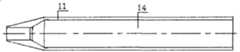
图1:逐级扩张套筒组合结构俯视示意图Figure 1: Schematic diagram of the top view of the combined structure of the step-by-step expansion sleeve
图2:图1中左视结构剖面示意图Figure 2: Schematic cross-sectional view of the left view structure in Figure 1
图3:图1中手柄结构俯视示意图Figure 3: Top view of the handle structure in Figure 1
图4:图1中手柄结构左视示意图Figure 4: Left view of the handle structure in Figure 1
图5:图2中逐级套筒结构示意图Figure 5: Schematic diagram of the step-by-step sleeve structure in Figure 2
图6:图2中卡环结构示意图Figure 6: Schematic diagram of the snap ring structure in Figure 2
图7:图6中卡环结构俯视示意图Figure 7: A schematic top view of the clasp structure in Figure 6
图8:图1中固定螺钉结构示意图Figure 8: Schematic diagram of the fixing screw structure in Figure 1
图9:螺钉导向外套筒组合结构俯视示意图Figure 9: Top view schematic diagram of the combined structure of the screw-guided outer sleeve
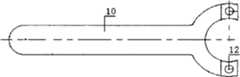
图10:图9中左视结构示意图Figure 10: Schematic diagram of the left view structure in Figure 9
图11:图10中半圆套筒结构剖面示意图Figure 11: Schematic cross-sectional view of the semicircular sleeve structure in Figure 10
图12:图11中右视示意图Figure 12: Schematic diagram of the right view in Figure 11
图13:图9中套筒凹手柄结构示意图Figure 13: Schematic diagram of the structure of the concave handle of the sleeve in Figure 9
图14:图13中俯视结构示意图Figure 14: Schematic diagram of the top view structure in Figure 13
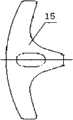
图15:图9中套筒凸手柄结构示意图Figure 15: Schematic diagram of the structure of the sleeve convex handle in Figure 9
图16:图15中俯视结构示意图Figure 16: Schematic diagram of the top view structure in Figure 15
图17:图2中销棒结构俯视示意图Figure 17: Top view of the pin structure in Figure 2
图18:销棒螺帽结构示意图Figure 18: Schematic diagram of pin nut structure
图19:开口器结构示意图Figure 19: Structural schematic diagram of the gag
图20:开口器扩孔锥杆结构示意图Figure 20: Schematic diagram of the structure of the opener reaming cone rod
图21:开口器手柄结构示意图Figure 21: Schematic diagram of the handle of the opener
图22:图21中左视示意图Figure 22: Schematic diagram of the left view in Figure 21
图23:图20中A-A剖面示意图Figure 23: Schematic diagram of section A-A in Figure 20
图24:螺钉置入器结构示意图Figure 24: Schematic diagram of the structure of the screw inserter
图25:螺钉置入器旋棒结构示意图Figure 25: Schematic diagram of the rotary rod structure of the screw inserter
图26:图25中B-B剖视结构示意图Figure 26: Schematic diagram of B-B section structure in Figure 25
图27:图24中套筒剖视结构示意图Figure 27: Schematic diagram of the cross-sectional structure of the sleeve in Figure 24
图28:图27中套筒左视结构示意图Figure 28: Schematic diagram of the left view of the sleeve in Figure 27
图29:图27中I放大结构示意图Figure 29: Schematic diagram of the enlarged structure of I in Figure 27
图30:图24中拉杆结构示意图Figure 30: Schematic diagram of the tie rod structure in Figure 24
图31:连接柄结构示意图Figure 31: Schematic diagram of the connecting handle structure
图32:连接柄俯视结构示意图Figure 32: Schematic diagram of the top view of the connecting handle
图33:连接柄右视结构示意图Figure 33: Schematic diagram of the right view of the connecting handle
图34:加长套结构示意图Figure 34: Schematic diagram of the structure of the extension sleeve
图35:连接套管结构示意图Figure 35: Schematic diagram of connecting sleeve structure
图36:图35中俯视结构示意图Figure 36: Schematic diagram of the top view structure in Figure 35
图37:微创加压植骨器结构示意图Figure 37: Schematic diagram of the minimally invasive pressurized bone graft
图38:图37中植骨筒结构示意图Figure 38: Schematic diagram of the structure of the bone graft cylinder in Figure 37
图39:图37中固定外筒结构示意图Figure 39: Schematic diagram of the structure of the fixed outer cylinder in Figure 37
图40:图37中枪式结构示意图Figure 40: Schematic diagram of gun structure in Figure 37
图41:微创加压植骨器右视结构示意图Figure 41: Schematic diagram of the structure of the minimally invasive pressurized bone graft device in right view
图42:撑开钳结构示意图Figure 42: Structural schematic diagram of spreading forceps
图43:撑开钳活动插销结构示意图Figure 43: Schematic diagram of the structure of the movable pin of the spreading pliers
图44:图43中活动插销俯视结构示意图Figure 44: Schematic diagram of the top view structure of the movable latch in Figure 43
图45:空心丝攻结构示意图Figure 45: Schematic diagram of hollow wire tapping structure
图1-图45中:In Figure 1-Figure 45:
1-逐级套筒、2-手柄、3-卡环、4-固定螺钉、5-上U槽、6-下U槽、7-套筒固定孔、8-套筒凹槽,件3卡环压入件2手柄凹槽内,件2套入件1套筒,卡环正好卡入套筒上的凹槽内,手柄可以自由旋转且不会从凹槽内松脱1-step-by-step sleeve, 2-handle, 3-clip, 4-fixing screw, 5-upper U groove, 6-lower U groove, 7-sleeve fixing hole, 8-sleeve groove, 3 pieces The ring is pressed into the handle groove of
9-套筒凹手柄、10-套筒凸手柄、11-圆套筒、12-销棒螺帽、13-棒销、14-圆套筒内通道、15-手柄、16-开口器轴向刻线、17-开口器扩孔锥杆、18-开口器锥头、19-空芯杆孔、24-套筒、20-手柄连接头、22-旋棒凹槽、23-拉杆、25-套筒外螺纹、26-塞头、27-拉杆空芯、28-连接柄头、29-连接柄杆、21-定位旋棒、-外套管、37-植骨筒、36-内顶芯、35-加压柄杆、33-固定外筒、34-枪式结构、38-枪式手柄9-sleeve concave handle, 10-sleeve convex handle, 11-round sleeve, 12-pin rod nut, 13-rod pin, 14-circular sleeve inner channel, 15-handle, 16-opener axial Score, 17-opener reaming cone rod, 18-opener cone head, 19-hollow rod hole, 24-sleeve, 20-handle connector, 22-rotary rod groove, 23-tie rod, 25- Sleeve external thread, 26-plug head, 27-tie rod hollow core, 28-connecting handle head, 29-connecting handle rod, 21-positioning rotary rod, -outer sleeve, 37-bone graft cylinder, 36-inner top core, 35-pressurized handle, 33-fixed outer cylinder, 34-gun structure, 38-gun handle
图42-图44中:1-左钳片、2-右钳片、3-调节螺母、4-调节螺杆、5-柱销、6-活动插销,7-打标处、8-刻度尺、9-手柄内凹槽、10-钳头、11-钳口In Fig. 42-Fig. 44: 1-left pliers, 2-right pliers, 3-adjusting nut, 4-adjusting screw, 5-column pin, 6-movable latch, 7-marking place, 8-scale, 9-Inner groove of the handle, 10-Pliers head, 11-Jaws
结合附图进一步说明本发明的组合结构:Further illustrate combined structure of the present invention in conjunction with accompanying drawing:
如图1-44所示的微创胸腰椎骨折椎弓根钉固定多节段置钉器械主要包括逐级扩张套筒、螺钉导向外套筒、螺钉置入器、联结棒、压力植骨器、空心丝攻、螺钉开口器、螺钉、撑开钳构成,其中:逐级扩张套筒是逐级套筒、旋转手柄、穿针孔等组成,其中逐级套筒是有一组内外套筒构成,即至少有两层以上直径不同、内外逐级相套的圆管所组成。所述的螺钉导向外套筒是有一对对称、匹配扣合的圆套筒、套筒手柄、棒销等组成,其中圆套筒是空芯半圆柱体和锥头构成,在半圆柱体上端安装有套筒手柄,两半圆柱体对接组合成一保护套筒,在半圆柱体上端的套筒手柄上下插接用销棒固定组合成一双套筒手柄。所述的螺钉置入器是有套筒、手柄、拉杆、塞头、连接柄、旋棒、外套管构成,其中,拉杆为空芯杆,手柄和塞头分别连接在拉杆的两端,手柄可与拉杆活动或固定连接,塞头与拉杆固定连接,塞头直接塞在螺钉钉尾部的凹槽内。所述的联接棒是有连接凸头、连接平头、连接棒体连接为一体所构成,其中,连接凸头是在连接棒体的上端轴向凸起,可与螺钉置入器旋转手柄上的凹槽匹配连接,通过螺钉置入器调节椎弓根螺钉的方向和位置;连接棒下端为连接平凸头,可与外套筒上端凹槽匹配连接,用于外套筒与螺钉置入器连接。所述的螺钉是指椎弓根螺钉,是有钉杆、钉尖部、钉尾部构成,它是在钉杆的两端分别与钉尖部、钉尾部连接,其中,钉杆上带有螺纹,钉尖部留有凸尖,钉尾部带有内螺纹的凹槽,该凹槽可塞入螺钉置入器的塞头或贯穿螺钉纵连杆,调节螺钉的方向和定位,螺钉准确定位并置入。所述的微创加压植骨器是由植骨筒、内顶芯、加压柄、固定外筒所组成,呈枪式结构,其中,在加压柄上装有固定外筒,固定外筒与植骨筒、内顶芯依次活动连接,加压柄是有顶杆、手枪拨柄、枪托构成,在枪托内安装有手枪拨柄,手枪拨柄顶在顶杆的齿道上,手枪拨柄沿着顶杆的齿道前后移动推动顶杆顶住内顶芯与植骨筒相套或退出,内顶芯可将植骨筒中的植骨材料压力顶出。所述的螺钉开口器是由扩孔锥杆、扩孔锥头、手柄等构成,它是在扩孔锥杆的两端分别连接着手柄和扩孔锥头,其中,扩孔锥头是由带微齿的钻头,用于钻开骨质点,空心丝攻准确钻出螺纹;手柄与扩孔锥杆可活动或固定连接,扩孔锥杆为空芯杆。所述的空心丝攻是由丝攻杆、丝攻头、手柄构成,它是在丝攻杆的两端分别连接丝攻头和手柄,其中,丝攻杆外带有螺纹齿道,丝攻杆为空芯杆,丝攻杆与丝攻头连为一体,丝攻头呈钻头状,手柄与丝攻杆可活动或固定连接。所述的开口钳是由左右钳片、调节螺母、调节螺杆、柱销、活动插销所构成,其中,左右钳片以柱销为支点,两钳头上均留有半圆缺口。上述器械最好选用医用高分子材料或医用金属材料或不锈钢材料加工制成。As shown in Figure 1-44, the minimally invasive pedicle screw fixation for thoracolumbar fractures with multi-segment screw placement equipment mainly includes step-by-step expansion sleeves, screw-guided outer sleeves, screw inserters, coupling rods, and pressure bone grafts. , hollow thread tap, screw opener, screw, and spreading pliers, wherein: the step-by-step expansion sleeve is composed of step-by-step sleeves, rotating handles, needle holes, etc., and the step-by-step sleeve is composed of a set of inner and outer sleeves , that is, it is composed of at least two layers of circular tubes with different diameters and the inner and outer layers are nested step by step. The screw-guiding outer sleeve is composed of a pair of symmetrical, matching and fastening circular sleeves, sleeve handles, rod pins, etc., wherein the circular sleeve is composed of a hollow semi-cylindrical body and a cone head, and the upper end of the semi-cylindrical body is A sleeve handle is installed, and the two half cylinders are butted and combined to form a protective sleeve, and the sleeve handles at the upper end of the half cylinder are plugged up and down and fixed with pins to form a pair of sleeve handles. The screw inserter is composed of a sleeve, a handle, a pull rod, a plug, a connecting handle, a rotary rod, and an outer casing, wherein the pull rod is a hollow rod, and the handle and the plug are respectively connected to two ends of the pull rod, and the handle It can be flexibly or fixedly connected with the pull rod, and the plug head is fixedly connected with the pull rod, and the plug head is directly plugged into the groove at the tail of the screw. The connecting rod is composed of a connecting protruding head, a connecting flat head and a connecting rod body connected as a whole, wherein the connecting protruding head is axially protruding from the upper end of the connecting rod body, and can be connected with the screw inserter on the rotating handle. Groove matching connection, adjust the direction and position of the pedicle screw through the screw inserter; the lower end of the connecting rod is a connecting flat convex head, which can be matched with the groove on the upper end of the outer sleeve, used for the outer sleeve and the screw inserter connect. The screw refers to a pedicle screw, which consists of a screw shank, a nail tip, and a nail tail. It is connected to the nail tip and the nail tail at the two ends of the screw shank respectively. , there is a convex point at the tip of the nail, and a groove with internal thread at the tail of the nail, which can be inserted into the plug head of the screw inserter or through the longitudinal connecting rod of the screw to adjust the direction and positioning of the screw, and the screw can be positioned accurately and Insert. The minimally invasive pressurized bone grafting device is composed of a bone graft cylinder, an inner top core, a pressurized handle, and a fixed outer cylinder, and is in a gun-like structure, wherein the fixed outer cylinder is mounted on the pressurized handle, and the fixed outer cylinder It is flexibly connected with the bone grafting cylinder and the inner top core in turn. The pressurized handle is composed of a push rod, a pistol handle and a gun stock. A pistol handle is installed in the gun stock. The handle moves back and forth along the tooth path of the ejector rod to push the ejector rod against the inner ejector core to fit or withdraw from the bone graft tube, and the inner ejector core can push out the bone graft material in the bone graft barrel under pressure. The screw opener is composed of a reaming cone rod, a reaming cone head, a handle, etc., and it is respectively connected with a handle and a reaming cone head at both ends of the reaming cone rod, wherein the reaming cone head is made of The drill bit with micro-tooth is used to drill the bone mass, and the hollow thread tap accurately drills the thread; the handle and the reaming cone rod can be connected flexibly or fixedly, and the reaming cone rod is a hollow core rod. The hollow tap is composed of a tap rod, a tap head and a handle, and the two ends of the tap rod are respectively connected with the tap head and the handle, wherein the tap rod has a threaded tooth track outside, and the tap rod The rod is a hollow rod, the tapping rod and the tapping head are connected as a whole, the tapping head is in the shape of a drill bit, and the handle and the tapping rod can be connected flexibly or fixedly. The open-end pliers are composed of left and right pliers, adjusting nuts, adjusting screw rods, column pins, and movable latches, wherein the left and right pliers use the column pins as fulcrums, and semicircular gaps are left on the heads of the two pliers. The above-mentioned instruments are preferably made of medical polymer materials or medical metal materials or stainless steel materials.
Claims (10)
Translated fromChinesePriority Applications (2)
| Application Number | Priority Date | Filing Date | Title |
|---|---|---|---|
| CN201210229622.2ACN103006312B (en) | 2010-09-03 | 2010-09-03 | Minimally invasive bone fracture screw inserts opener |
| CN2010102713109ACN101912300B (en) | 2009-09-29 | 2010-09-03 | Minimally invasive pedicle screw fixation for thoracolumbar fractures |
Applications Claiming Priority (3)
| Application Number | Priority Date | Filing Date | Title |
|---|---|---|---|
| CN200910019532 | 2009-09-29 | ||
| CN200910019532.9 | 2009-09-29 | ||
| CN2010102713109ACN101912300B (en) | 2009-09-29 | 2010-09-03 | Minimally invasive pedicle screw fixation for thoracolumbar fractures |
Related Child Applications (4)
| Application Number | Title | Priority Date | Filing Date |
|---|---|---|---|
| CN2012102296701ADivisionCN103070721A (en) | 2010-09-03 | 2010-09-03 | Minimally-invasive thoracolumbar vertebral fracture repositor |
| CN201210229622.2ADivisionCN103006312B (en) | 2010-09-03 | 2010-09-03 | Minimally invasive bone fracture screw inserts opener |
| CN2012102296218ADivisionCN103126757A (en) | 2009-09-29 | 2010-09-03 | Minimally invasive fracture fixation multi-section screw fixation device |
| CN2012102275921ADivisionCN102920496A (en) | 2010-09-03 | 2010-09-03 | Minimally-invasive pressurization bone grafting instrument |
Publications (2)
| Publication Number | Publication Date |
|---|---|
| CN101912300A CN101912300A (en) | 2010-12-15 |
| CN101912300Btrue CN101912300B (en) | 2012-08-22 |
Family
ID=43320068
Family Applications (2)
| Application Number | Title | Priority Date | Filing Date |
|---|---|---|---|
| CN2010102713109AExpired - Fee RelatedCN101912300B (en) | 2009-09-29 | 2010-09-03 | Minimally invasive pedicle screw fixation for thoracolumbar fractures |
| CN2012102296218APendingCN103126757A (en) | 2009-09-29 | 2010-09-03 | Minimally invasive fracture fixation multi-section screw fixation device |
Family Applications After (1)
| Application Number | Title | Priority Date | Filing Date |
|---|---|---|---|
| CN2012102296218APendingCN103126757A (en) | 2009-09-29 | 2010-09-03 | Minimally invasive fracture fixation multi-section screw fixation device |
Country Status (1)
| Country | Link |
|---|---|
| CN (2) | CN101912300B (en) |
Families Citing this family (13)
| Publication number | Priority date | Publication date | Assignee | Title |
|---|---|---|---|---|
| CN102247201B (en)* | 2011-08-12 | 2012-10-31 | 贺新宁 | Percutaneous minimally invasive pedicle screw/rod internal fixation system |
| CN104665920B (en)* | 2015-03-30 | 2017-03-15 | 蔡鸿敏 | A kind of passage preparation tool of pelvis crista iliaca external fixing rack screw |
| CN105596077A (en)* | 2016-02-06 | 2016-05-25 | 贺新宁 | Universal screw-setting device for pedicle screw |
| CN105816228A (en)* | 2016-02-26 | 2016-08-03 | 邓宇 | T-shaped fixing rod of thoracolumbar vertebral fracture posterior micro-wound screw-rod fixation percutaneous reduction system |
| CN106691525A (en)* | 2017-01-06 | 2017-05-24 | 南京市六合区人民医院 | Fixing system for transplant in anterior cruciate ligament reconstruction |
| CN108158669A (en)* | 2018-01-16 | 2018-06-15 | 王珏 | A kind of spinal pedicle puts nail soft tissue protective device |
| CN109330677A (en)* | 2018-11-22 | 2019-02-15 | 自贡市第四人民医院(自贡市急救中心) | A personalized atlantoaxial pedicle screw step-by-step navigation template device and its making method |
| CN110811717B (en)* | 2019-11-01 | 2023-10-13 | 上海市第六人民医院 | A rivet component that facilitates one-step insertion and a one-step rivet insertion method |
| CN111529044A (en)* | 2020-06-05 | 2020-08-14 | 江苏创立康医疗器械有限公司 | Holding device |
| CN112545629A (en)* | 2021-01-13 | 2021-03-26 | 西安市红会医院 | Scapular glenoid bone grafting device under minimally invasive condition |
| CN114652368B (en)* | 2022-02-10 | 2024-07-09 | 山东威高骨科材料股份有限公司 | Minimally invasive three-stage expansion sleeve |
| CN114917001A (en)* | 2022-05-27 | 2022-08-19 | 上海三友医疗器械股份有限公司 | spreader |
| CN118044870B (en)* | 2024-04-16 | 2024-06-28 | 四川大学华西医院 | Spinal column dislocation resetting device |
Citations (4)
| Publication number | Priority date | Publication date | Assignee | Title |
|---|---|---|---|---|
| CN2407724Y (en)* | 1999-12-31 | 2000-11-29 | 邢台矿业(集团)有限责任公司总医院 | Stereotaxic needle for pedicle |
| CN2754574Y (en)* | 2004-12-21 | 2006-02-01 | 华中科技大学同济医学院附属同济医院 | Vertebral pedicle screw implantation guider |
| CN201157401Y (en)* | 2008-02-25 | 2008-12-03 | 梁道臣 | Minimally invasive percutaneous transpedicular surgery positioning and guiding device |
| CN101327146A (en)* | 2008-07-31 | 2008-12-24 | 中国人民解放军第三军医大学第二附属医院 | A double-slot channel-connected percutaneous pedicle screw internal fixation system |
Family Cites Families (6)
| Publication number | Priority date | Publication date | Assignee | Title |
|---|---|---|---|---|
| US7476240B2 (en)* | 2004-02-06 | 2009-01-13 | Depuy Spine, Inc. | Devices and methods for inserting a spinal fixation element |
| US7666189B2 (en)* | 2004-09-29 | 2010-02-23 | Synthes Usa, Llc | Less invasive surgical system and methods |
| EP1767161A1 (en)* | 2005-09-22 | 2007-03-28 | Zimmer Spine, Inc. | Spinal fixation rod contouring system |
| US8608746B2 (en)* | 2008-03-10 | 2013-12-17 | DePuy Synthes Products, LLC | Derotation instrument with reduction functionality |
| KR20110033199A (en)* | 2008-06-19 | 2011-03-30 | 신세스 게엠바하 | Bone Screw Percussion Augmented Implants, Systems and Technologies |
| CN202761431U (en)* | 2012-07-03 | 2013-03-06 | 张强 | Minimally invasive fracture bolt-imbedding machine capable of fixing multiple segments |
- 2010
- 2010-09-03CNCN2010102713109Apatent/CN101912300B/ennot_activeExpired - Fee Related
- 2010-09-03CNCN2012102296218Apatent/CN103126757A/enactivePending
Patent Citations (4)
| Publication number | Priority date | Publication date | Assignee | Title |
|---|---|---|---|---|
| CN2407724Y (en)* | 1999-12-31 | 2000-11-29 | 邢台矿业(集团)有限责任公司总医院 | Stereotaxic needle for pedicle |
| CN2754574Y (en)* | 2004-12-21 | 2006-02-01 | 华中科技大学同济医学院附属同济医院 | Vertebral pedicle screw implantation guider |
| CN201157401Y (en)* | 2008-02-25 | 2008-12-03 | 梁道臣 | Minimally invasive percutaneous transpedicular surgery positioning and guiding device |
| CN101327146A (en)* | 2008-07-31 | 2008-12-24 | 中国人民解放军第三军医大学第二附属医院 | A double-slot channel-connected percutaneous pedicle screw internal fixation system |
Also Published As
| Publication number | Publication date |
|---|---|
| CN103126757A (en) | 2013-06-05 |
| CN101912300A (en) | 2010-12-15 |
Similar Documents
| Publication | Publication Date | Title |
|---|---|---|
| CN101912300B (en) | Minimally invasive pedicle screw fixation for thoracolumbar fractures | |
| US10952749B2 (en) | Surgical tools having application for spinal surgical procedures and method of use | |
| JP5164571B2 (en) | Percutaneous tissue expansion system and related methods | |
| JP5108060B2 (en) | Apparatus and method for stabilizing bone structures | |
| CA2548729A1 (en) | Methods and devices for minimally invasive spinal fixation element placement | |
| US20220151608A1 (en) | Reconfigurable suture needles being transformable between higher profile configurations and lower profile configurations | |
| CN102973314A (en) | Thoracolumbar spine posterior minimally invasive bone cement spine internal fixation system and application | |
| US20140207191A1 (en) | System and Method for Performing Spinal Stabilization | |
| CN105596077A (en) | Universal screw-setting device for pedicle screw | |
| CN205493991U (en) | Follow closely ware on pedicle of vertebral arch screw general hollow | |
| CN202313683U (en) | Posterior thoracolumbar minimally-invasive bone cement spinal internal fixing system | |
| CN205493985U (en) | Pedicle of vertebral arch screw general is put to bind and is put | |
| CN104783881B (en) | A kind of clavicular fracture Wicresoft Medullary fixation device | |
| CN204708960U (en) | A kind of clavicular fracture Wicresoft Medullary fixation device | |
| CN202761431U (en) | Minimally invasive fracture bolt-imbedding machine capable of fixing multiple segments | |
| CN210962257U (en) | Minimally invasive fixing device for tibial intercondylar eminence fracture | |
| CN210749450U (en) | Spinal full cortical bone screw and spinal positioning and orientation device | |
| CN113633362A (en) | Minimally invasive surgery tool for knee joint posterior cruciate ligament insertion fracture | |
| CN205493992U (en) | A wicresoft's soft tissue expansion subassembly that is used for pedicle of vertebral arch screw to put nail | |
| CN221997973U (en) | A simple Kirschner wire guide | |
| CN213910470U (en) | Vertebroplasty instrument | |
| CN210931756U (en) | Be used for percutaneous wicresoft's pedicle of vertebral arch screw to put into device | |
| CN103006312B (en) | Minimally invasive bone fracture screw inserts opener | |
| CN210931752U (en) | Pedicle of vertebral arch minimal access surgery apparatus | |
| JP2022522119A (en) | Telescopic nails and related drilling equipment |
Legal Events
| Date | Code | Title | Description |
|---|---|---|---|
| C06 | Publication | ||
| PB01 | Publication | ||
| C10 | Entry into substantive examination | ||
| SE01 | Entry into force of request for substantive examination | ||
| C14 | Grant of patent or utility model | ||
| GR01 | Patent grant | ||
| C53 | Correction of patent of invention or patent application | ||
| CB03 | Change of inventor or designer information | Inventor after:Zhang Qiang Inventor after:Jiao Feng Inventor after:Wang Dawei Inventor after:Hu Tao Inventor after:Han Leixiang Inventor after:Li Shaobo Inventor after:Ji Yuqing Inventor after:Hu Qiao Inventor after:Cong Wei Inventor after:Dong Xiaoguang Inventor after:Li Huadao Inventor after:Zhang Peng Inventor after:Lv Fuxin Inventor after:Zhang Yijun Inventor before:Zhang Qiang Inventor before:Ji Yuqing Inventor before:Hu Qiao Inventor before:Cong Wei Inventor before:Dong Xiaoguang Inventor before:Li Huadao | |
| COR | Change of bibliographic data | Free format text:CORRECT: INVENTOR; FROM: ZHANG QIANG JI YUQING HU QIAO CONG WEI DONG XIAOGUANG LI HUADAO TO: ZHANG QIANG JI YUQING HU QIAO CONG WEI DONG XIAOGUANG LI HUADAO ZHANG PENG LV FUXIN ZHANG YIJUN JIAO FENG WANG DAWEI HU TAO HAN LEIXIANG LI SHAOBO | |
| DD01 | Delivery of document by public notice | Addressee:Zhang Qiang Document name:Notification to Pay the Fees | |
| DD01 | Delivery of document by public notice | Addressee:Zhang Qiang Document name:payment instructions | |
| DD01 | Delivery of document by public notice | ||
| DD01 | Delivery of document by public notice | Addressee:Zhang Qiang Document name:Notice of termination of patent right | |
| DD01 | Delivery of document by public notice | ||
| CF01 | Termination of patent right due to non-payment of annual fee | Granted publication date:20120822 Termination date:20200903 | |
| CF01 | Termination of patent right due to non-payment of annual fee |