CN101912251B - Endoscopic image processing apparatus - Google Patents
Endoscopic image processing apparatusDownload PDFInfo
- Publication number
- CN101912251B CN101912251BCN2010102261065ACN201010226106ACN101912251BCN 101912251 BCN101912251 BCN 101912251BCN 2010102261065 ACN2010102261065 ACN 2010102261065ACN 201010226106 ACN201010226106 ACN 201010226106ACN 101912251 BCN101912251 BCN 101912251B
- Authority
- CN
- China
- Prior art keywords
- image
- endoscope
- lesion
- insertion state
- diseased region
- Prior art date
- Legal status (The legal status is an assumption and is not a legal conclusion. Google has not performed a legal analysis and makes no representation as to the accuracy of the status listed.)
- Active
Links
Images


Classifications
- A—HUMAN NECESSITIES
- A61—MEDICAL OR VETERINARY SCIENCE; HYGIENE
- A61B—DIAGNOSIS; SURGERY; IDENTIFICATION
- A61B1/00—Instruments for performing medical examinations of the interior of cavities or tubes of the body by visual or photographical inspection, e.g. endoscopes; Illuminating arrangements therefor
- A61B1/04—Instruments for performing medical examinations of the interior of cavities or tubes of the body by visual or photographical inspection, e.g. endoscopes; Illuminating arrangements therefor combined with photographic or television appliances
- A61B1/05—Instruments for performing medical examinations of the interior of cavities or tubes of the body by visual or photographical inspection, e.g. endoscopes; Illuminating arrangements therefor combined with photographic or television appliances characterised by the image sensor, e.g. camera, being in the distal end portion
- A—HUMAN NECESSITIES
- A61—MEDICAL OR VETERINARY SCIENCE; HYGIENE
- A61B—DIAGNOSIS; SURGERY; IDENTIFICATION
- A61B1/00—Instruments for performing medical examinations of the interior of cavities or tubes of the body by visual or photographical inspection, e.g. endoscopes; Illuminating arrangements therefor
- A61B1/00002—Operational features of endoscopes
- A61B1/00043—Operational features of endoscopes provided with output arrangements
- A61B1/00045—Display arrangement
- A61B1/0005—Display arrangement combining images e.g. side-by-side, superimposed or tiled
- G—PHYSICS
- G06—COMPUTING OR CALCULATING; COUNTING
- G06T—IMAGE DATA PROCESSING OR GENERATION, IN GENERAL
- G06T7/00—Image analysis
- G06T7/0002—Inspection of images, e.g. flaw detection
- G06T7/0012—Biomedical image inspection
- G—PHYSICS
- G16—INFORMATION AND COMMUNICATION TECHNOLOGY [ICT] SPECIALLY ADAPTED FOR SPECIFIC APPLICATION FIELDS
- G16H—HEALTHCARE INFORMATICS, i.e. INFORMATION AND COMMUNICATION TECHNOLOGY [ICT] SPECIALLY ADAPTED FOR THE HANDLING OR PROCESSING OF MEDICAL OR HEALTHCARE DATA
- G16H40/00—ICT specially adapted for the management or administration of healthcare resources or facilities; ICT specially adapted for the management or operation of medical equipment or devices
- G16H40/60—ICT specially adapted for the management or administration of healthcare resources or facilities; ICT specially adapted for the management or operation of medical equipment or devices for the operation of medical equipment or devices
- G16H40/63—ICT specially adapted for the management or administration of healthcare resources or facilities; ICT specially adapted for the management or operation of medical equipment or devices for the operation of medical equipment or devices for local operation
- G—PHYSICS
- G16—INFORMATION AND COMMUNICATION TECHNOLOGY [ICT] SPECIALLY ADAPTED FOR SPECIFIC APPLICATION FIELDS
- G16Z—INFORMATION AND COMMUNICATION TECHNOLOGY [ICT] SPECIALLY ADAPTED FOR SPECIFIC APPLICATION FIELDS, NOT OTHERWISE PROVIDED FOR
- G16Z99/00—Subject matter not provided for in other main groups of this subclass
- A—HUMAN NECESSITIES
- A61—MEDICAL OR VETERINARY SCIENCE; HYGIENE
- A61B—DIAGNOSIS; SURGERY; IDENTIFICATION
- A61B34/00—Computer-aided surgery; Manipulators or robots specially adapted for use in surgery
- A61B34/10—Computer-aided planning, simulation or modelling of surgical operations
- A61B2034/101—Computer-aided simulation of surgical operations
- A61B2034/102—Modelling of surgical devices, implants or prosthesis
- A—HUMAN NECESSITIES
- A61—MEDICAL OR VETERINARY SCIENCE; HYGIENE
- A61B—DIAGNOSIS; SURGERY; IDENTIFICATION
- A61B34/00—Computer-aided surgery; Manipulators or robots specially adapted for use in surgery
- A61B34/10—Computer-aided planning, simulation or modelling of surgical operations
- A61B2034/101—Computer-aided simulation of surgical operations
- A61B2034/105—Modelling of the patient, e.g. for ligaments or bones
- A—HUMAN NECESSITIES
- A61—MEDICAL OR VETERINARY SCIENCE; HYGIENE
- A61B—DIAGNOSIS; SURGERY; IDENTIFICATION
- A61B34/00—Computer-aided surgery; Manipulators or robots specially adapted for use in surgery
- A61B34/20—Surgical navigation systems; Devices for tracking or guiding surgical instruments, e.g. for frameless stereotaxis
- A61B2034/2046—Tracking techniques
- A61B2034/2051—Electromagnetic tracking systems
- A—HUMAN NECESSITIES
- A61—MEDICAL OR VETERINARY SCIENCE; HYGIENE
- A61B—DIAGNOSIS; SURGERY; IDENTIFICATION
- A61B34/00—Computer-aided surgery; Manipulators or robots specially adapted for use in surgery
- A61B34/20—Surgical navigation systems; Devices for tracking or guiding surgical instruments, e.g. for frameless stereotaxis
- A—HUMAN NECESSITIES
- A61—MEDICAL OR VETERINARY SCIENCE; HYGIENE
- A61B—DIAGNOSIS; SURGERY; IDENTIFICATION
- A61B90/00—Instruments, implements or accessories specially adapted for surgery or diagnosis and not covered by any of the groups A61B1/00 - A61B50/00, e.g. for luxation treatment or for protecting wound edges
- A61B90/36—Image-producing devices or illumination devices not otherwise provided for
- A61B90/361—Image-producing devices, e.g. surgical cameras
- G—PHYSICS
- G06—COMPUTING OR CALCULATING; COUNTING
- G06T—IMAGE DATA PROCESSING OR GENERATION, IN GENERAL
- G06T2207/00—Indexing scheme for image analysis or image enhancement
- G06T2207/10—Image acquisition modality
- G06T2207/10068—Endoscopic image
- G—PHYSICS
- G06—COMPUTING OR CALCULATING; COUNTING
- G06T—IMAGE DATA PROCESSING OR GENERATION, IN GENERAL
- G06T2207/00—Indexing scheme for image analysis or image enhancement
- G06T2207/30—Subject of image; Context of image processing
- G06T2207/30004—Biomedical image processing
- G06T2207/30028—Colon; Small intestine
Landscapes
- Health & Medical Sciences (AREA)
- Engineering & Computer Science (AREA)
- Life Sciences & Earth Sciences (AREA)
- Medical Informatics (AREA)
- General Health & Medical Sciences (AREA)
- Surgery (AREA)
- Biomedical Technology (AREA)
- Public Health (AREA)
- Nuclear Medicine, Radiotherapy & Molecular Imaging (AREA)
- Physics & Mathematics (AREA)
- Radiology & Medical Imaging (AREA)
- Animal Behavior & Ethology (AREA)
- Heart & Thoracic Surgery (AREA)
- Molecular Biology (AREA)
- Pathology (AREA)
- Optics & Photonics (AREA)
- Biophysics (AREA)
- Veterinary Medicine (AREA)
- General Physics & Mathematics (AREA)
- Computer Vision & Pattern Recognition (AREA)
- Quality & Reliability (AREA)
- Theoretical Computer Science (AREA)
- Business, Economics & Management (AREA)
- General Business, Economics & Management (AREA)
- Epidemiology (AREA)
- Primary Health Care (AREA)
- Endoscopes (AREA)
- Image Processing (AREA)
- Image Analysis (AREA)
- Instruments For Viewing The Inside Of Hollow Bodies (AREA)
Abstract
Translated fromChinese
Description
Translated fromChinese本申请是申请日为2008年6月6日,申请号为200810108920.X,发明名称为“内窥镜图像处理装置”的发明专利申请的分案申请。This application is a divisional application of an invention patent application with an application date of June 6, 2008, an application number of 200810108920.X, and an invention title of "endoscopic image processing device".
技术领域technical field
本发明涉及内窥镜图像处理装置,尤其涉及对在插入被检体内的内窥镜中伴随时间的经过而拍摄的被摄体的像所对应的图像的显示状态进行控制的内窥镜图像处理装置。The present invention relates to an endoscope image processing device, and more particularly, to endoscope image processing for controlling the display state of an image corresponding to an image of a subject captured by an endoscope inserted into a subject with the passage of time device.
背景技术Background technique
包括内窥镜等而构成的内窥镜系统以往被广泛应用于工业领域和医疗领域等。尤其医疗领域的内窥镜系统主要用在活体内的各种器官的观察等用途上。并且,作为在前述用途中使用的内窥镜系统,例如有专利文献1中提出的电子内窥镜系统。An endoscope system including an endoscope and the like has been widely used in industrial fields, medical fields, and the like. In particular, endoscope systems in the medical field are mainly used for purposes such as observation of various organs in a living body. Furthermore, as an endoscope system used for the aforementioned application, there is an electronic endoscope system proposed in
专利文献1的电子内窥镜系统构成为具有:拍摄单元,其利用配设在内窥镜前端部的拍摄元件拍摄被检者的体内;位置检测单元,其检测所述内窥镜前端部的位置信息;记录单元,其在预定的定时记录通过所述拍摄单元所拍摄的图像,作为与拍摄时通过所述位置检测单元检测的所述位置信息相关联的静态图像;显示单元,其显示记录在所述记录单元中的所述静态图像和与该静态图像相关联的位置信息,而且将通过所述拍摄单元拍摄的图像与通过所述位置检测单元检测的所述位置信息一起显示为动态图像。因此,专利文献1的电子内窥镜系统根据前述结构,可以确定内窥镜拍摄的图像的对应部位。The electronic endoscope system of
另一方面,在使用内窥镜进行的各种观察中,尤其在观察大肠时,例如将来有可能实现下述观察方法:在护士或技师等辅助人员将内窥镜插入大肠最深处即回盲部后,医师一面抽拔内窥镜一面进行病变部位的观察。目前,如果是熟练的医师,则多采用以下观察方法:首先该医师亲自把内窥镜插入所述回盲部,然后该医师亲自一面抽拔该内窥镜一面进行仔细观察和治疗等。On the other hand, among various observations using an endoscope, especially when observing the large intestine, for example, in the future, it may be possible to implement an observation method in which an auxiliary person such as a nurse or a technician inserts the endoscope into the deepest part of the large intestine, that is, the ileocecal area. After the surgery, the doctor draws out the endoscope and observes the lesion. At present, if it is a skilled doctor, the following observation methods are often used: first, the doctor personally inserts the endoscope into the ileocecal region, and then the doctor personally draws out the endoscope for careful observation and treatment.
[专利文献1]日本特开2006-223850号公报[Patent Document 1] Japanese Patent Laid-Open No. 2006-223850
在采用前述观察方法时,医师需要加大注意力,例如以便做到在抽拔内窥镜时不会漏看内窥镜插入时所确认的病变部位。因此,在前述观察方法中,减轻医师负担并且可以防止漏看内窥镜插入时所确认的病变部位这样的有效方法的实现成为课题。When using the aforementioned observation method, the doctor needs to pay more attention, for example, so that the lesion confirmed when the endoscope is inserted will not be overlooked when the endoscope is pulled out. Therefore, among the above-mentioned observation methods, it is a problem to realize an effective method that can reduce the burden on the physician and prevent the lesion site confirmed when the endoscope is inserted from being overlooked.
另一方面,专利文献1的电子内窥镜系统具有用于将拍摄图像时的内窥镜前端部的位置信息与该图像关联起来的结构,但不具有可以防止在采用前述观察方法时可能产生的病变部位的漏看的结构,例如不具有能够在抽拔内窥镜时显示内窥镜插入时所确认的病变部位的相关信息的结构。换言之,专利文献1的电子内窥镜系统不具有能够解决在前述观察方法中产生的前述问题的结构。On the other hand, the electronic endoscope system of
发明内容Contents of the invention
本发明就是鉴于上述情况而完成的,其目的在于,提供一种内窥镜图像处理装置,在抽拔内窥镜时显示在插入内窥镜时获取的病变部位的相关信息,由此与以往相比可以提高使用内窥镜的观察效率。The present invention has been made in view of the above circumstances, and an object of the present invention is to provide an endoscope image processing device that displays information on lesion parts acquired when the endoscope is inserted when the endoscope is pulled out, thereby making it different from conventional ones. Observation efficiency using an endoscope can be improved compared to that.
本发明的第1方式的内窥镜图像处理装置的特征在于,该内窥镜图像处理装置具有:图像获取部,其获取与在插入被检体内的内窥镜中伴随时间经过而拍摄的被摄体的像对应的图像;病变部位检测部,其每当获取所述图像时检测所述图像内的病变部位;插入状态数据获取部,其获取表示插入所述被检体内的内窥镜的插入状态的插入状态数据;存储部,其把所述图像获取部获取所述病变部位图像的定时的所述插入状态数据所对应的所述内窥镜的插入状态的相关信息,与所述病变部位图像相关联地进行存储,其中所述病变部位图像是被所述病变部位检测部检测到病变部位的图像;显示部,其显示所述图像获取部获取的图像和存储在所述存储部中的与内窥镜的插入状态有关的信息;以及图像显示控制部,其根据所述病变部位检测部的检测结果,控制所述图像获取部获取的图像中的所述病变部位图像和所述插入状态数据的显示状态。The endoscope image processing apparatus according to the first aspect of the present invention is characterized in that the endoscope image processing apparatus includes: an image acquisition unit that acquires an image of the subject imaged with the passage of time in the endoscope inserted into the subject. an image corresponding to the image of the subject; a lesion detection unit that detects a lesion in the image each time the image is acquired; an insertion state data acquisition unit that acquires information representing the endoscope inserted into the subject. Insertion state data of the insertion state; a storage unit that combines information related to the insertion state of the endoscope corresponding to the insertion state data at the timing at which the image acquisition unit acquires the image of the lesion with the lesion Part images are stored in association, wherein the lesion part image is an image of a lesion part detected by the lesion part detection part; a display part displays the image acquired by the image acquisition part and stores in the storage part information related to the insertion state of the endoscope; and an image display control unit that controls the image of the lesion in the image acquired by the image acquisition unit and the insertion The display state of the state data.
本发明的第2方式的内窥镜图像处理装置的特征在于,所述内窥镜的插入状态的相关信息包括所述内窥镜的插入长度、所述内窥镜插入后的经过时间和所述内窥镜的插入形状中的至少一个。The endoscope image processing device according to the second aspect of the present invention is characterized in that the information on the insertion state of the endoscope includes the insertion length of the endoscope, the elapsed time after insertion of the endoscope, and the at least one of the insertion shapes of the endoscope.
根据本发明的内窥镜图像处理装置,在抽拔内窥镜时显示在插入内窥镜时获取的病变部位的相关信息,由此与以往相比可以提高使用内窥镜的观察效率。According to the endoscope image processing device of the present invention, when the endoscope is pulled out, the information on the lesion site obtained when the endoscope is inserted is displayed, thereby improving the efficiency of observation using the endoscope compared with conventional ones.
附图说明Description of drawings
图1是表示本发明的实施方式涉及的使用图像处理装置的活体观测系统的主要部分的结构的一例的图。FIG. 1 is a diagram showing an example of a configuration of a main part of a living body observation system using an image processing device according to an embodiment of the present invention.
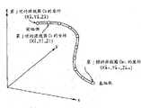
图2是表示在图1的内窥镜插入状态检测装置中被检测的、设于图1的内窥镜的插入部中的源线圈的坐标的图。2 is a diagram showing coordinates of a source coil provided in an insertion portion of the endoscope in FIG. 1 , which are detected by the endoscope insertion state detection device in FIG. 1 .
图3是表示在检测到具有隆起形状的病变部位时,图1的图像处理装置进行的处理的一部分的流程图。3 is a flowchart showing a part of processing performed by the image processing device in FIG. 1 when a lesion having a raised shape is detected.
图4是表示在检测到具有隆起形状的病变部位时,图1的图像处理装置紧接着图3的处理而进行的处理的流程图。FIG. 4 is a flowchart showing processing performed by the image processing device in FIG. 1 subsequent to the processing in FIG. 3 when a lesion having a raised shape is detected.
图5是表示利用图1的图像处理装置推测的三维模型的一例的图。FIG. 5 is a diagram showing an example of a three-dimensional model estimated by the image processing device in FIG. 1 .
图6是表示在图5的三维模型中,作为用于检测具有隆起形状的病变部位的处理对象的体素组所在区域的一例的图。6 is a diagram showing an example of a region where a voxel group is located as a processing target for detecting a lesion having a raised shape in the three-dimensional model of FIG. 5 .
图7是表示在检测到病变部位时,在图1的图像处理装置具有的显示屏上显示的图像等的一例的图。FIG. 7 is a diagram showing an example of an image displayed on a display screen included in the image processing device in FIG. 1 when a lesion is detected.
图8是表示在图1的图像处理装置具有的显示屏上显示的内窥镜图像的显示方法的一例的图。FIG. 8 is a diagram showing an example of a method of displaying an endoscopic image displayed on the display screen included in the image processing device of FIG. 1 .
图9是表示在图1的图像处理装置具有的显示屏上显示的内窥镜图像的显示方法的、与图8不同的示例的图。FIG. 9 is a diagram illustrating an example of a display method of an endoscopic image displayed on a display screen included in the image processing device of FIG. 1 , which is different from FIG. 8 .
符号说明Symbol Description
1活体观测系统;2内窥镜装置;3内窥镜插入状态检测装置;4图像处理装置;6内窥镜;8视频处理器;21插入状态分析装置;25PC;28显示屏;101插入状态信息;102插入形状图像;103内窥镜图像。1 living body observation system; 2 endoscope device; 3 endoscope insertion state detection device; 4 image processing device; 6 endoscope; 8 video processor; 21 insertion state analysis device; 25PC; 28 display screen; 101 insertion state information; 102 insert shape image; 103 endoscopic image.
具体实施方式Detailed ways
以下,参照附图说明本发明的实施方式。图1~图9涉及本发明的实施方式。图1是表示本发明的实施方式涉及的使用图像处理装置的活体观测系统的主要部分的结构的一例的图。图2是表示在图1的内窥镜插入状态检测装置中被检测的、设于图1的内窥镜的插入部中的源线圈的坐标的图。图3是表示在检测到具有隆起形状的病变部位时,图1的图像处理装置进行的处理的一部分的流程图。图4是表示在检测到具有隆起形状的病变部位时,图1的图像处理装置紧接着图3的处理而进行的处理的流程图。图5是表示利用图1的图像处理装置推测的三维模型的一例的图。图6是表示在图5的三维模型中,作为用于检测具有隆起形状的病变部位的处理对象的体素组所在区域的一例的图。图7是表示在检测到病变部位时,在图1的图像处理装置具有的显示屏上显示的图像等的一例的图。图8是表示在图1的图像处理装置具有的显示屏上显示的内窥镜图像的显示方法的一例的图。图9是表示在图1的图像处理装置具有的显示屏上显示的内窥镜图像的显示方法的、与图8不同的示例的图。Hereinafter, embodiments of the present invention will be described with reference to the drawings. 1 to 9 relate to an embodiment of the present invention. FIG. 1 is a diagram showing an example of a configuration of a main part of a living body observation system using an image processing device according to an embodiment of the present invention. 2 is a diagram showing coordinates of a source coil provided in an insertion portion of the endoscope in FIG. 1 , which are detected by the endoscope insertion state detection device in FIG. 1 . 3 is a flowchart showing a part of processing performed by the image processing device in FIG. 1 when a lesion having a raised shape is detected. FIG. 4 is a flowchart showing processing performed by the image processing device in FIG. 1 subsequent to the processing in FIG. 3 when a lesion having a raised shape is detected. FIG. 5 is a diagram showing an example of a three-dimensional model estimated by the image processing device in FIG. 1 . 6 is a diagram showing an example of a region where a voxel group is located as a processing target for detecting a lesion having a raised shape in the three-dimensional model of FIG. 5 . FIG. 7 is a diagram showing an example of an image displayed on a display screen included in the image processing device in FIG. 1 when a lesion is detected. FIG. 8 is a diagram showing an example of a method of displaying an endoscopic image displayed on the display screen included in the image processing device of FIG. 1 . FIG. 9 is a diagram illustrating an example of a display method of an endoscopic image displayed on a display screen included in the image processing device of FIG. 1 , which is different from FIG. 8 .
活体观测系统1如图1所示,其构成为具有:内窥镜装置2,其可以利用内窥镜6观察被检者的内部;内窥镜插入状态检测装置3,其检测被插入该被检者内部的内窥镜6的插入状态,并且把该插入状态作为插入状态数据输出;以及图像处理装置4,其进行对应从内窥镜插入状态检测装置3输出的插入状态数据的各种处理。As shown in FIG. 1, the living
内窥镜装置2构成为具有:内窥镜6,其可以插入存在于被检者内部的大肠等中,并且拍摄该被检者内部的被摄体,并作为拍摄信号输出;光源装置7,其向内窥镜6提供用于照明该被摄体的照明光;视频处理器8,其对从内窥镜6输出的拍摄信号进行信号处理,并作为影像信号输出;以及监视器9,其根据从视频处理器8输出的影像信号,显示通过内窥镜6拍摄的被摄体的像作为内窥镜图像。The
内窥镜6具有可以插入被检者内部的细长插入部11和设于插入部11后端的操作部12。在插入部11的内部插通着光导13,其一端侧配置在插入部11的前端部14,同时另一端侧可以连接在光源装置7上。由此,从光源装置7提供的照明光通过光导13从设于插入部11的前端部14的未图示的照明窗射出。The
另外,在插入部11的前端部14的后端侧设有可以自由弯曲地构成的未图示的弯曲部。并且,所述未图示的弯曲部可以根据设于操作部12上的未图示的弯曲操作把手等的操作而弯曲。In addition, a not-illustrated bending portion configured to be freely bendable is provided on the rear end side of the
在前端部14上,在与未图示的照明窗相邻设置的未图示的观察窗上安装有物镜15。并且,在物镜15的成像位置配置有由电荷耦合元件(简称为CCD)等构成的拍摄元件16的拍摄面。An
拍摄元件16通过信号线与视频处理器8连接,拍摄通过物镜15成像的被摄体的像,并作为拍摄信号输出给视频处理器8。The
视频处理器8进行用于根据从拍摄元件16输出的拍摄信号生成影像信号的信号处理。并且,视频处理器8把通过所述信号处理生成的影像信号例如RGB信号输出给监视器9。并且,在监视器9的显示面上显示在拍摄元件16中拍摄的被摄体的像,作为内窥镜图像。The video processor 8 performs signal processing for generating a video signal from the imaging signal output from the
另外,光源装置7例如在提供由R(红)、G(绿)、B(蓝)构成的面顺序的照明光时,把与提供各种光的期间同步的同步信号输出给视频处理器8。此时,视频处理器8与从光源装置7输出的所述同步信号同步地进行信号处理。In addition, the
在内窥镜6的操作部12上,除所述未图示的弯曲操作把手外,还设有可以进行释放指示等的指示的未图示的开关。The
并且,在内窥镜6的插入部11的内部,在长度方向上具有预定间隔地配置多个源线圈C0、C1、...、CM-1(简称为C0~CM-1)。并且,源线圈C0~CM-1根据从内窥镜插入状态检测装置3输出的驱动信号,在各自的周围产生磁场。Furthermore, inside the
并且,在源线圈C0~CM-1中产生的磁场,被内窥镜插入状态检测装置3具有的内置了多个读出线圈的读出线圈单元19检测到。Then, the magnetic fields generated in the source coils C0 to CM-1 are detected by the
内窥镜插入状态检测装置3构成为具有:读出线圈单元19,其检测在设于内窥镜6中的源线圈C0~CM-1中产生的磁场;插入状态分析装置21,其可以根据由读出线圈单元19检测的磁场的检测信号,分析包括插入部11的形状推测在内的插入部11的插入状态;以及显示器22,其显示由插入状态分析装置21推测的插入部11的形状。The endoscope insertion
读出线圈单元19配置在患者躺卧的床的周边部等处,检测源线圈C0~CM-1产生的磁场,把所检测的该磁场作为检测信号输出给插入状态分析装置21。The
插入状态分析装置21根据检测信号,进行源线圈C0~CM-1的各个位置坐标数据的计算,并且根据所计算的该位置坐标数据推测插入部11的插入形状。并且,插入状态分析装置21生成所推测的插入部11的插入形状的影像信号,并把所生成的影像信号例如RGB信号输出给显示器22。由此,在显示器22的显示画面上图像显示插入部11的插入形状。另外,插入状态分析装置21在进行基于内窥镜6的观察的过程中,连续生成插入部11的插入形状的相关信息、插入部11的插入长度、插入部11插入后的经过时间和形状显示属性等插入状态数据,并通过通信端口21a输出给图像处理装置4。The insertion state analyzer 21 calculates the position coordinate data of each of the source coils C0 to CM-1 based on the detection signal, and estimates the insertion shape of the
并且,本实施方式的内窥镜插入状态检测装置3,通过在未图示的操作面板等上进行指示和输入,对在通过插入状态分析装置21的形状检测处理而生成,然后显示在显示器22上的插入形状的图像的旋转角和放大缩小比率等形状显示属性进行变更。In addition, the endoscope insertion
另外,视频处理器8具有未图示的操作面板,用于输入例如患者姓名、出生年月日、性别、年龄、患者代码和检查日期时间等信息即检查信息。并且,在所述未图示的操作面板中输入的检查信息被叠加在通过视频处理器8生成的影像信号上,并输出给监视器9,并且还通过通信端口8a发送给图像处理装置4。In addition, the video processor 8 has an operation panel (not shown) for inputting examination information such as patient name, date of birth, sex, age, patient code, and examination date and time. Then, the inspection information input on the operation panel (not shown) is superimposed on the video signal generated by the video processor 8, and output to the
作为内窥镜图像处理装置的图像处理装置4具有:个人计算机(以下简称为PC)25,其根据从内窥镜插入状态检测装置3输出的插入状态数据和从视频处理器8输出的检查信息,进行各种处理;鼠标26和键盘27,其可以对PC 25进行各种指示和输入;以及显示屏28,其可以显示通过PC 25的所述各种处理生成的图像和信息等。The image processing device 4 as an endoscope image processing device has: a personal computer (hereinafter referred to simply as PC) 25, which uses the insertion state data output from the endoscope insertion
PC 25具有:通信端口25a,其获取从内窥镜插入状态检测装置3的插入状态分析装置21的通信端口21a输出的插入状态数据;通信端口25b,其获取从所述内窥镜装置2的视频处理器8的通信端口8a输出的检查信息;动态图像输入板25c,其把通过视频处理器8生成的动态图像的影像信号转换为预定的压缩图像数据;进行各种信号处理的CPU 31;处理程序存储部32,其存储有在CPU 31的该各种信号处理中使用的处理程序;存储器33,其存储通过CPU 31处理后的数据等;硬盘(以下简称为HDD)34,其存储通过CPU 31处理后的图像数据等。并且,PC 25具有的各个部分通过总线35相互连接。The
图像处理装置4的动态图像输入板25c被输入例如具有预定的帧频(30帧/秒)的Y/C信号,作为在视频处理器8中生成的动态图像的影像信号。并且,动态图像输入板25c使用例如MJPEG形式等预定的压缩形式,把所述动态图像的影像信号转换为压缩动态图像数据,并且把该压缩动态图像数据输出给HDD34等。The moving image input board 25 c of the image processing device 4 receives, for example, a Y/C signal having a predetermined frame rate (30 frames/second) as an image signal of a moving image generated by the video processor 8 . Furthermore, the moving image input board 25c converts the video signal of the moving image into compressed moving image data using a predetermined compression format such as MJPEG format, and outputs the compressed moving image data to the
另外,在通信端口25a中获取的插入状态数据和在通信端口25b中获取的检查信息,例如被输出给存储器33,由此保存在PC 25内。In addition, the insertion state data acquired by the
显示屏28具有例如和触摸屏相同的功能,可以显示通过PC 25的各种处理生成的图像和信息等,并且可以把针对所显示的图像的输入内容信号化并输出给PC 25。The
在此,说明在内窥镜插入状态检测装置3生成插入状态数据时进行的处理。Here, the processing performed when the endoscope insertion
内窥镜插入状态检测装置3的插入状态分析装置21根据从内窥镜6的拍摄元件16输出1帧的拍摄信号的定时,生成包括内置于内窥镜6的插入部11中的M个源线圈C0~CM-1的三维坐标的插入状态数据。并且,插入状态分析装置21把所述插入状态数据输出给图像处理装置4,同时根据所述插入状态数据生成插入部11的插入形状的图像,把该插入形状的图像输出给显示器22。The insertion state analysis device 21 of the endoscope insertion
另外,第j帧(其中,j=0、1、2...)中从插入部11的前端侧起第i个(其中,i=0、1、...、M-1)源线圈Ci的三维坐标,如图2所示被表示为(Xij、Yij、Zij)。In addition, the i-th (where i=0, 1, . The three-dimensional coordinates of Ci are expressed as (Xij , Yij , Zij) as shown in FIG. 2 .
包括由该内窥镜插入状态检测装置3检测的源线圈C0~CM-1的坐标系数据的插入状态数据,构成为与各个帧相关的帧数据(即,第0帧数据、第1帧数据、...),并依次发送给图像处理装置4。并且,各个帧数据构成为包括插入状态数据的生成时间、显示属性、附属信息和源线圈的(三维)坐标等数据。The insertion state data including the coordinate system data of the source coils C0 to CM-1 detected by the endoscope insertion
并且,线圈坐标数据是分别表示依次配置在插入部11的前端侧到基端侧(操作部12侧)的源线圈C0~CM-1的三维坐标的数据。另外,内窥镜插入状态检测装置3的检测范围外的源线圈的三维坐标,例如被设定为可以得知在检测范围外的预定的坐标值(例如(0、0、0))。Furthermore, the coil coordinate data are data representing three-dimensional coordinates of the source coils C0 to CM-1 sequentially arranged from the distal end side to the proximal end side (operating
下面,说明本实施方式的活体观测系统1的作用。Next, the operation of the living
在护士或技师等辅助人员把内窥镜6的插入部11从被检体的肛门侧插入体腔内时,利用设于插入部11的前端部14的拍摄元件16拍摄存在于该体腔内的被摄体。通过拍摄元件16拍摄的被摄体的像随着时间经过而被拍摄,并作为拍摄信号输出,在通过视频处理器8进行信号处理并转换为影像信号后,输出给监视器9。由此,在监视器9上显示通过拍摄元件16拍摄的被摄体的像,作为内窥镜图像。When an assistant such as a nurse or a technician inserts the
内窥镜插入状态检测装置3在读出线圈单元19中检测从各个源线圈C0~CM-1发生的磁场,并且在插入状态分析装置21中根据对应该磁场而输出的检测信号推测插入部11的插入形状。由此,在显示器22上显示在插入状态分析装置21中推测的插入部11的插入形状。The endoscope insertion
并且,在视频处理器8中生成的影像信号通过通信端口8a和25b输出给CPU 31。And, the video signal generated in the video processor 8 is output to the
具有作为图像获取部和病变部位检测部的功能的CPU 31,根据所输入的影像信号和写入处理程序存储部32中的处理程序,获取通过内窥镜6拍摄的被摄体的像所对应的图像,并且每当获取该图像时,进行用于检测该图像内的病变部位的处理。The
在此,说明为了在通过内窥镜6拍摄的被摄体的像中检测具有隆起形状的病变部位,CPU 31进行的处理的一例。另外,以后叙述的用于检测病变部位的处理,针对从视频处理器8输出的影像信号中的各个帧的图像进行。Here, an example of processing performed by the
首先,CPU31根据所输入的影像信号,抽出通过内窥镜6拍摄的被摄体的像中包含的所有边缘部并将其细线化,计算被细线化的该所有边缘部中的一个边缘部E的长度L(图3中的步骤S1、步骤S2和步骤S3)。另外,CPU 31判定一个边缘部E的长度L是否比阈值thL1长、并且比阈值thL2短(图3中的步骤S4)。First, the
并且,CPU 31在检测到一个边缘部E的长度L为预定的阈值thL1以下的长度、或者在阈值thL2以上时,不把该一个边缘部E视为病变引起的边缘部,进行后述的图3中的步骤S11所示的处理。CPU 31在检测到一个边缘部E的长度L比阈值thL1长而且比阈值thL2短时,利用控制点Cn(n=1、2、...、N)N等分该一个边缘部E(图3中的步骤S5)。In addition, when the
另外,CPU 31获取从一个边缘部E的中点Cc引出的法线NCc,并且获取从各个控制点Cn引出的N条法线NCn(图3中的步骤S6)。然后,CPU 31检测N条法线NCn中与法线NCc相交的法线条数Na(图3中的步骤S7)。In addition, the
并且,CPU 31进行N条法线NCn中与法线NCc相交的法线条数Na是否多于阈值tha的判断(图3中的步骤S8)。并且,CPU 31在检测到与法线NCc相交的法线条数Na多于阈值tha时,把一个边缘部E中包含的像素组ip判断为候选病变部位的边缘部中包含的像素组,把该像素组ip具有的各个像素中的变量edge(i)的值设为ON(图3中的步骤S9)。另外,CPU 31在检测到与法线NCc相交的法线条数Na在阈值tha以下时,把一个边缘部E中包含的像素组ip判断为不是病变引起的边缘部中包含的像素组,把该像素组ip具有的各个像素中的变量edge(i)的值设为OFF(图3中的步骤S10)。And, the
然后,CPU 31判断是否已对所抽出的全部边缘部结束处理(图3中的步骤S11)。并且,CPU 31在检测到没有结束对所抽出的全部边缘部的处理时,对其他的一个边缘部实施前述的从图3中的步骤S3到步骤S10的处理。并且,CPU 31在检测到已结束对所抽出的全部边缘部的处理时,结束用于抽出二维图像中的边缘部的一系列处理。Then, the
CPU 31把作为通过对所抽出的全部边缘部进行以上叙述的一系列处理所得到的处理结果的、像素组ip中的变量edge(i)的值,暂时存储在存储器33中。The
并且,CPU 31根据从视频处理器8输出的影像信号的亮度信息等,例如进行几何学转换等处理,由此获取推测通过内窥镜6拍摄的被摄体的像的三维模型时需要的图像数据。换言之,CPU 31例如通过几何学转换等处理,生成对应二维图像中的各个像素的体素,并且获取该体素作为用于推测三维模型的图像数据。即,像素组ip通过前述处理被转换为体素组ib。In addition, the
CPU 31通过前述处理,获得包括变量edge(i)为ON的体素组ib的平面即边界平面的数据,作为用于推测通过内窥镜6拍摄的被摄体的像的三维模型的图像数据。由此,通过内窥镜6拍摄的被摄体的像,例如在把z轴方向作为利用内窥镜6观察时的视野方向时,被推测为具有图5所示形状的三维模型。Through the aforementioned processing, the
然后,CPU 31根据所述边界平面的数据,抽出z坐标为最大的一个体素,作为变量edge(i)为ON的体素组ib中位于内窥镜6的视野方向的最里侧的预定的一个体素,并把该一个体素的z坐标设定为Maxz(图4中的步骤S21)。Then, according to the data of the boundary plane, the
并且,CPU 31检测z坐标小于Maxz的体素组rb,作为用于推测通过内窥镜6拍摄的被摄体的像的三维模型的图像数据而获得的全部体素中、相比所述一个体素的位置位于内窥镜6的视野方向跟前侧的体素(图4中的步骤S22)。另外,所述体素组rb例如是由位于图6所示区域内的R个体素构成的体素组。In addition, the
另外,CPU 31把变量a设定为1后,抽出体素组rb具有的R个体素中的一个体素即Ba(a=1、2、...、R-1、R),并且计算ShapeIndex值SBa和Curvedness值CBa,作为该一个体素Ba的形状特征量(图4中的步骤S23、步骤S24和步骤S25)。In addition, after the
另外,前述的ShapeIndex值和Curvedness值例如可以使用与USPatent Application Publication No.20030223627记载的方法相同的方法计算。因此,在本实施方式中,省略说明一个体素Ba的ShapeIndex值和Curvedness值的计算方法。In addition, the aforementioned ShapeIndex value and Curvedness value can be calculated using the same method as described in US Patent Application Publication No. 20030223627, for example. Therefore, in this embodiment, the description of the calculation method of the ShapeIndex value and the Curvedness value of one voxel Ba is omitted.
并且,CPU 31进行ShapeIndex值SBa与预先设定的ShapeIndex值的阈值Sth(例如0.9)的比较,并且进行Curvedness值CBa与预先设定的Curvedness值的阈值Cth(例如0.2)的比较(图4中的步骤S26)。换言之,CPU 31通过进行前述处理,进行抽出三维模型被推测为凸型形状的体素组的处理,作为用于检测通过内窥镜6拍摄的被摄体的像是否是具有隆起形状的病变部位的处理。And, the
并且,CPU 31在检测到ShapeIndex值SBa大于阈值Sth、而且Curvedness值CBa大于阈值Cth时,把一个体素Ba判断为构成具有隆起形状的病变部位的一部分的体素,把该一个体素Ba的变量ryuuki(Ba)的值设为ON(图4中的步骤S27)。In addition, when the
并且,CPU 31在检测到ShapeIndex值SBa为阈值Sth以下、或者Curvedness值CBa为阈值Cth以下时,判断一个体素Ba不是构成具有隆起形状的病变部位的一部分的体素,把该一个体素Ba的变量ryuuki(Ba)的值设为OFF(图4中的步骤S28)。Furthermore, when the
然后,CPU 31进行是否已对R个体素全部进行前述处理的判定,即,进行是否是变量a=R的判定(图4中的步骤S29)。Then, the
并且,CPU 31在检测到不是a=R时,进行向变量i加1的处理(图4中的步骤S30),然后再次进行前述的从图4中的步骤S24~步骤S29所示的处理。And, when
并且,CPU 31在检测到a=R时(图4中的步骤S29),结束用于检测通过内窥镜6拍摄的被摄体的像的三维模型中的隆起形状的一系列处理。Then, when the
然后,CPU 31把作为通过对R个体素全部进行以上叙述的一系列处理而得到的处理结果的ryukki(Ba)的值,暂时存储在存储器33中。Then, the
并且,CPU31根据ryukki(Ba)的值为ON的各个体素的位置,检测位于与该各个体素的位置对应的位置的二维图像上的各个像素。Then, the
CPU 31对从视频处理器8输出的影像信号中的各个帧的图像实施以上叙述的一系列处理,由此检测通过内窥镜6拍摄的被摄体的像中包含的息肉等具有隆起形状的病变部位。The
另外,具有作为图像显示控制部和插入状态信息获取部的功能的CPU 31进行以下控制:根据从视频处理器8输出的影像信号、基于前述一系列处理的病变部位的检测结果、通过通信端口21a和25a输入的插入状态数据,获取例如检测到病变部位的场景图像、检测到病变部位时的插入部11的插入形状、检测到病变部位时的插入部11的插入长度、以及从插入部11被插入到获取该图像的经过时间的各个信息,并彼此相关联地存储在HDD 34中,并且在预定的定时从HDD 34读入该各个信息并输出给显示屏28。CPU 31通过进行前述控制,在显示屏28上一并显示例如图7所示的至少包括前述的插入长度和经过时间的插入状态信息101、表示检测到病变部位时的插入部11的插入形状的插入形状图像102、和检测到病变部位的场景的内窥镜图像103。另外,插入状态信息101中包含的各个信息和插入形状图像102(如图7所示)不限于全部显示在显示屏28上,例如也可以显示至少一个。In addition, the
并且,前述预定的定时例如也可以是在插入部11被插入时刚刚检测到病变部位后的定时,还可以是在插入部11的前端部14到达大肠内的回盲部后,设于内窥镜6的未图示的插入结束按钮被按下的定时。In addition, the aforementioned predetermined timing may be, for example, the timing immediately after the lesion is detected when the
并且,显示于显示屏28的内容不限于图7所示内容,例如在检测到多个病变部位时,也可以首先只一览显示内窥镜图像103的缩略图像,然后对所选择的一幅图像进行图7所示的显示。另外,所述一览显示的显示顺序例如是基于检测到病变部位的定时、插入长度和经过时间中至少任一方的顺序。Moreover, the content displayed on the
根据以上叙述的作用,医师可以在辅助人员结束插入部11的插入之前,确认有无病变部位、病变部位的个数及病变部位的大致位置。另外,根据以上叙述的作用,医师可以在抽拔插入部11时一面参照显示于显示屏28上的内窥镜图像103,一面进行观察。According to the functions described above, the doctor can check whether there is a lesion, the number of the lesion, and the approximate position of the lesion before the assistant completes the insertion of the
另外,在本实施方式中,图像处理装置4还可以具有以下结构,即,可以在插入部11插入时标识所发现的病变部位的图像的结构,以及在抽拔插入部11时,在前端部14接近对应于具有该标识的图像的位置时进行通知的结构。In addition, in this embodiment, the image processing device 4 may also have the following structure, that is, a structure that can mark the image of the lesion found when the
并且,显示于显示屏28上的内窥镜图像103不限于只显示检测到病变部位的场景的静态图像,例如图8所示,也可以通过CPU 31的控制,把以检测到病变部位的场景的静态图像Ic的获取定时为基准的前后t秒的图像,作为动态图像连续显示。Moreover, the
具体地讲,例如,作为图像显示控制部的CPU 31可以进行以下控制:使显示屏28连续显示(再现或逆向再现)从插入部11插入时获取的图像I1到In的N幅图像中的所述静态图像Ic、和在时间上位于所述静态图像Ic的获取定时之前和/或之后的t秒的图像即预定幅数的图像,作为动态图像。Specifically, for example, the
并且,显示于显示屏28上的内窥镜图像103不限于只显示检测到病变部位的场景的静态图像,例如也可以通过CPU 31的控制,简要再现从插入部11插入时获取的图像I1到In的N幅图像,作为动态图像。In addition, the
所述简要再现例如利用以下方法实现,即,包括从图像I1到In的N幅图像的、按照时间顺序的一系列动态图像中被检测到病变部位的场景图像,作为暂时停止图像(静态图像)显示在显示屏28(的显示有内窥镜图像103的部分)上,关于除此之外的图像,以快速再现的方式显示在显示屏28(的显示有内窥镜图像103的部分)上。并且,如图9所示,作为从图像I1到In的N幅图像中例如被检测到病变部位的场景图像,在获取了图像Ii、图像Ii+1和图像Ii+2各幅图像时,通过CPU 31的控制,从插入部11的插入开始时(的图像I1)到插入结束时(的图像In)的一系列动态图像中的该各幅图像,作为暂时停止图像(静态图像)显示在显示屏28(的显示有内窥镜图像103的部分)上,关于该各幅图像之外的图像,以快速再现的方式显示在显示屏28(的显示有内窥镜图像103的部分)上。另外,所述快速再现的速度例如是比内窥镜6的拍摄元件16的拍摄速度快的速度。The brief reproduction is realized, for example, by using the following method, that is, the scene image of the detected lesion in a series of dynamic images in time sequence including N images from imagesI1 toIn , as a temporarily stopped image (static image) is displayed on the display screen 28 (the part where the
另外,显示在显示屏28上的内窥镜图像103不限于只显示检测到病变部位的场景的静态图像,例如也可以通过CPU 31的控制,作为动态图像,逆向简要再现从插入部11插入时获取的图像I1到In的N幅图像。In addition, the
所述逆向简要再现例如利用以下方法实现,即,包括从图像In到I1的N幅图像的、按照时间逆序的一系列动态图像中被检测到病变部位的场景的图像,作为暂时停止图像(静态图像)显示在显示屏28(的显示有内窥镜图像103的部分)上,关于除此之外的图像,以快速再现的方式显示在显示屏28(的显示有内窥镜图像103的部分)上。并且,如图9所示,作为从图像I1到In的N幅图像中例如被检测到病变部位的场景的图像,在获取了图像Ii、图像Ii+1和图像Ii+2各幅图像时,通过CPU 31的控制,从插入部11的插入结束时(的图像In)到插入开始时(的图像I1)的一系列动态图像中的该各幅图像,作为暂时停止图像(静态图像)显示在显示屏28(的显示有内窥镜图像103的部分)上,关于该各幅图像之外的图像,以快速逆向再现的方式显示在显示屏28(的显示有内窥镜图像103的部分)上。另外,所述快速逆向再现的速度例如是比内窥镜6的拍摄元件16的拍摄速度快的速度。The reverse brief reproduction is realized, for example, by using the following method, that is, the image of the scene where the lesion is detected in a series of dynamic images in reverse order of time, including N images from images In to I1 , is used as a temporary stop image (Still image) is displayed on the display screen 28 (the part where the
如上所述,本实施方式涉及的图像处理装置4(具有该图像处理装置4而构成的活体观测系统1)具有以下结构,即,可以在抽拔插入部11时(或者在此之前的定时),使显示屏28显示在插入部11插入时获取的被检测到病变部位的场景的图像及信息。由此,本实施方式涉及的图像处理装置4(具有该图像处理装置4而构成的活体观测系统1),与以往相比,可以提高使用内窥镜的观察效率。并且,前述效果在采用由不同的人进行内窥镜的插入及抽拔的观察方法时尤其显著。As described above, the image processing device 4 (the living
并且,本实施方式涉及的图像处理装置4(具有该图像处理装置4而构成的活体观测系统1),例如在使内窥镜往返于所期望部位的附近进行观察的情况下,也可以发挥前述效果。Furthermore, the image processing device 4 (the living
另外,本实施方式涉及的图像处理装置4(具有该图像处理装置4而构成的活体观测系统1),具有在检测病变部位时可以通过图像处理检测息肉等具有隆起形状的病变部位的结构,但不限于此,例如也可以具有以下结构,即,内窥镜6的操作者根据检测到病变部位的定时按下未图示的病变检测按钮等,由此对CPU 31进行指示,使其识别该病变部位的存在。In addition, the image processing device 4 according to the present embodiment (the living
并且,本发明不限于上述实施方式,当然可以在不脱离本发明宗旨的范围内进行各种变形和应用。In addition, the present invention is not limited to the above-described embodiments, and of course various modifications and applications can be made without departing from the gist of the present invention.
Claims (2)
Applications Claiming Priority (2)
| Application Number | Priority Date | Filing Date | Title |
|---|---|---|---|
| JP2007-150921 | 2007-06-06 | ||
| JP2007150921AJP2008301968A (en) | 2007-06-06 | 2007-06-06 | Endoscopic image processing device |
Related Parent Applications (1)
| Application Number | Title | Priority Date | Filing Date |
|---|---|---|---|
| CN200810108920XADivisionCN101317749B (en) | 2007-06-06 | 2008-06-06 | Endoscope image processing device |
Publications (2)
| Publication Number | Publication Date |
|---|---|
| CN101912251A CN101912251A (en) | 2010-12-15 |
| CN101912251Btrue CN101912251B (en) | 2012-08-08 |
Family
ID=39522407
Family Applications (2)
| Application Number | Title | Priority Date | Filing Date |
|---|---|---|---|
| CN200810108920XAActiveCN101317749B (en) | 2007-06-06 | 2008-06-06 | Endoscope image processing device |
| CN2010102261065AActiveCN101912251B (en) | 2007-06-06 | 2008-06-06 | Endoscopic image processing apparatus |
Family Applications Before (1)
| Application Number | Title | Priority Date | Filing Date |
|---|---|---|---|
| CN200810108920XAActiveCN101317749B (en) | 2007-06-06 | 2008-06-06 | Endoscope image processing device |
Country Status (4)
| Country | Link |
|---|---|
| US (1) | US20080303898A1 (en) |
| EP (1) | EP2014219A3 (en) |
| JP (1) | JP2008301968A (en) |
| CN (2) | CN101317749B (en) |
Families Citing this family (69)
| Publication number | Priority date | Publication date | Assignee | Title |
|---|---|---|---|---|
| US9474440B2 (en) | 2009-06-18 | 2016-10-25 | Endochoice, Inc. | Endoscope tip position visual indicator and heat management system |
| US10130246B2 (en) | 2009-06-18 | 2018-11-20 | Endochoice, Inc. | Systems and methods for regulating temperature and illumination intensity at the distal tip of an endoscope |
| US10524645B2 (en) | 2009-06-18 | 2020-01-07 | Endochoice, Inc. | Method and system for eliminating image motion blur in a multiple viewing elements endoscope |
| JP5589366B2 (en) | 2009-11-27 | 2014-09-17 | ソニー株式会社 | Information processing apparatus, information processing method, and program thereof |
| JP5065538B2 (en)* | 2010-09-14 | 2012-11-07 | オリンパスメディカルシステムズ株式会社 | ENDOSCOPE SYSTEM AND METHOD OF OPERATING VISUAL DEFECT JUDGING SYSTEM |
| JP5492729B2 (en)* | 2010-09-28 | 2014-05-14 | 富士フイルム株式会社 | Endoscopic image recording apparatus, operation method of endoscopic image recording apparatus, and program |
| JP5636247B2 (en)* | 2010-10-06 | 2014-12-03 | Hoya株式会社 | Electronic endoscope processor and electronic endoscope apparatus |
| JP5601970B2 (en)* | 2010-10-26 | 2014-10-08 | Hoya株式会社 | Electronic endoscope processor and electronic endoscope apparatus |
| US10663714B2 (en) | 2010-10-28 | 2020-05-26 | Endochoice, Inc. | Optical system for an endoscope |
| US9706908B2 (en) | 2010-10-28 | 2017-07-18 | Endochoice, Inc. | Image capture and video processing systems and methods for multiple viewing element endoscopes |
| WO2012106310A1 (en)* | 2011-02-04 | 2012-08-09 | The Penn State Research Foundation | Method and device for determining the location of an endoscope |
| US10517464B2 (en) | 2011-02-07 | 2019-12-31 | Endochoice, Inc. | Multi-element cover for a multi-camera endoscope |
| JP2013116138A (en)* | 2011-12-01 | 2013-06-13 | Sony Corp | Image processing apparatus and method |
| WO2013154130A1 (en)* | 2012-04-11 | 2013-10-17 | オリンパス株式会社 | Endoscope device and endoscope system |
| CN104203073A (en)* | 2012-10-18 | 2014-12-10 | 奥林巴斯医疗株式会社 | Image processing device and image processing method |
| US10595714B2 (en) | 2013-03-28 | 2020-03-24 | Endochoice, Inc. | Multi-jet controller for an endoscope |
| US12207796B2 (en) | 2013-03-28 | 2025-01-28 | Endochoice Inc. | Multi-jet controller for an endoscope |
| US9636003B2 (en) | 2013-06-28 | 2017-05-02 | Endochoice, Inc. | Multi-jet distributor for an endoscope |
| WO2014182723A1 (en) | 2013-05-07 | 2014-11-13 | Endochoice, Inc. | White balance enclosed for use with a multi-viewing elements endoscope |
| US9949623B2 (en) | 2013-05-17 | 2018-04-24 | Endochoice, Inc. | Endoscope control unit with braking system |
| US10064541B2 (en) | 2013-08-12 | 2018-09-04 | Endochoice, Inc. | Endoscope connector cover detection and warning system |
| US9943218B2 (en) | 2013-10-01 | 2018-04-17 | Endochoice, Inc. | Endoscope having a supply cable attached thereto |
| US9968242B2 (en) | 2013-12-18 | 2018-05-15 | Endochoice, Inc. | Suction control unit for an endoscope having two working channels |
| WO2015112747A2 (en) | 2014-01-22 | 2015-07-30 | Endochoice, Inc. | Image capture and video processing systems and methods for multiple viewing element endoscopes |
| US20150313445A1 (en)* | 2014-05-01 | 2015-11-05 | Endochoice, Inc. | System and Method of Scanning a Body Cavity Using a Multiple Viewing Elements Endoscope |
| US11234581B2 (en) | 2014-05-02 | 2022-02-01 | Endochoice, Inc. | Elevator for directing medical tool |
| EP3689219B1 (en) | 2014-07-21 | 2023-08-30 | EndoChoice, Inc. | Multi-focal, multi-camera endoscope systems |
| US10542877B2 (en) | 2014-08-29 | 2020-01-28 | Endochoice, Inc. | Systems and methods for varying stiffness of an endoscopic insertion tube |
| JP5959787B1 (en)* | 2014-11-27 | 2016-08-02 | オリンパス株式会社 | Image reproduction apparatus and image reproduction program |
| EP3235241B1 (en) | 2014-12-18 | 2023-09-06 | EndoChoice, Inc. | System for processing video images generated by a multiple viewing elements endoscope |
| WO2016112034A2 (en) | 2015-01-05 | 2016-07-14 | Endochoice, Inc. | Tubed manifold of a multiple viewing elements endoscope |
| US10376181B2 (en) | 2015-02-17 | 2019-08-13 | Endochoice, Inc. | System for detecting the location of an endoscopic device during a medical procedure |
| US10078207B2 (en) | 2015-03-18 | 2018-09-18 | Endochoice, Inc. | Systems and methods for image magnification using relative movement between an image sensor and a lens assembly |
| CN114795471A (en)* | 2015-04-06 | 2022-07-29 | 直观外科手术操作公司 | System and method for registration compensation in image-guided surgery |
| US10401611B2 (en) | 2015-04-27 | 2019-09-03 | Endochoice, Inc. | Endoscope with integrated measurement of distance to objects of interest |
| US10516865B2 (en) | 2015-05-17 | 2019-12-24 | Endochoice, Inc. | Endoscopic image enhancement using contrast limited adaptive histogram equalization (CLAHE) implemented in a processor |
| JP6188991B2 (en)* | 2015-07-16 | 2017-08-30 | オリンパス株式会社 | Endoscope, insertion shape observation device |
| US20170119474A1 (en) | 2015-10-28 | 2017-05-04 | Endochoice, Inc. | Device and Method for Tracking the Position of an Endoscope within a Patient's Body |
| EP4579310A3 (en) | 2015-11-24 | 2025-09-10 | Endochoice, Inc. | Disposable air/water and suction valves for an endoscope |
| WO2017115442A1 (en)* | 2015-12-28 | 2017-07-06 | オリンパス株式会社 | Image processing apparatus, image processing method, and image processing program |
| JP2019507628A (en) | 2016-02-24 | 2019-03-22 | エンドチョイス インコーポレイテッドEndochoice, Inc. | Circuit board assembly for multiple view element endoscopes using CMOS sensors |
| US10292570B2 (en) | 2016-03-14 | 2019-05-21 | Endochoice, Inc. | System and method for guiding and tracking a region of interest using an endoscope |
| EP3429478B1 (en) | 2016-06-21 | 2021-04-21 | Endochoice, Inc. | Endoscope system with multiple connection interfaces to interface with different video data signal sources |
| JP6465452B2 (en)* | 2016-12-22 | 2019-02-06 | オリンパス株式会社 | Endoscope insertion shape observation device |
| WO2018138828A1 (en)* | 2017-01-26 | 2018-08-02 | オリンパス株式会社 | Image processing device, operation method, and program |
| WO2018165620A1 (en)* | 2017-03-09 | 2018-09-13 | The Board Of Trustees Of The Leland Stanford Junior University | Systems and methods for clinical image classification |
| US20200129042A1 (en)* | 2017-05-25 | 2020-04-30 | Nec Corporation | Information processing apparatus, control method, and program |
| CN107256552B (en)* | 2017-06-14 | 2020-08-18 | 成都微识医疗设备有限公司 | Polyp image recognition system and method |
| EP3682791B1 (en) | 2017-09-15 | 2023-12-20 | FUJIFILM Corporation | Medical image processing device |
| US11179203B2 (en)* | 2017-10-26 | 2021-11-23 | Biosense Webster (Israel) Ltd. | Position-tracking-enabling connector for an ear-nose-throat (ENT) tool |
| CN111295127B (en)* | 2017-10-31 | 2022-10-25 | 富士胶片株式会社 | Examination support device, endoscope device, and recording medium |
| CN108024061A (en)* | 2017-12-08 | 2018-05-11 | 合肥工业大学 | The hardware structure and image processing method of medical endoscope artificial intelligence system |
| JP2021164490A (en)* | 2018-04-10 | 2021-10-14 | オリンパス株式会社 | Medical system |
| JP7170032B2 (en) | 2018-04-13 | 2022-11-11 | 富士フイルム株式会社 | Image processing device, endoscope system, and image processing method |
| EP3795062A4 (en) | 2018-05-17 | 2021-06-16 | FUJIFILM Corporation | ENDOSCOPE DEVICE, ENDOSCOPE OPERATING PROCEDURE, AND PROGRAM |
| WO2020008651A1 (en)* | 2018-07-06 | 2020-01-09 | オリンパス株式会社 | Endoscope image processing device, endoscope image processing method, and endoscope image processing program |
| WO2020017212A1 (en)* | 2018-07-20 | 2020-01-23 | 富士フイルム株式会社 | Endoscope system |
| CN112584740B (en)* | 2018-08-20 | 2024-04-05 | 富士胶片株式会社 | Medical image processing apparatus |
| JP7078494B2 (en)* | 2018-08-24 | 2022-05-31 | 富士フイルム株式会社 | Display control device, endoscope system, display control method, and display control program |
| KR102168485B1 (en)* | 2018-10-02 | 2020-10-21 | 한림대학교 산학협력단 | Endoscopic device and method for diagnosing gastric lesion based on gastric endoscopic image obtained in real time |
| CN113365545B (en)* | 2019-02-13 | 2024-12-10 | 奥林巴斯株式会社 | Image recording device, image recording method, and image recording program |
| WO2021020067A1 (en)* | 2019-07-31 | 2021-02-04 | 富士フイルム株式会社 | Endoscope shape display control device, method of operating endoscope shape display control device, and program for operating endoscope shape display control device |
| US12419492B2 (en)* | 2020-03-31 | 2025-09-23 | Nec Corporation | Information processing device, display method, and non-transitory computer-readable medium for storing a program for lesion detection processing supporting decision making using machine learning |
| WO2022014077A1 (en)* | 2020-07-15 | 2022-01-20 | 富士フイルム株式会社 | Endoscope system and method for operating same |
| CN113040707A (en)* | 2020-12-02 | 2021-06-29 | 泰州国安医疗用品有限公司 | Human tissue lesion parameter analysis platform and method |
| JP7619893B2 (en)* | 2021-06-07 | 2025-01-22 | 株式会社エビデント | ENDOSCOPIC APPARATUS, ENDOSCOPIC SYSTEM, OPERATION METHOD OF ENDOSCOPIC APPARATUS, AND PROGRAM |
| WO2023089719A1 (en)* | 2021-11-18 | 2023-05-25 | 日本電気株式会社 | Video editing device, video editing method, and recording medium |
| CN115778546B (en)* | 2023-02-07 | 2023-05-09 | 武汉楚精灵医疗科技有限公司 | Intelligent auxiliary method and device for endoscopic submucosal dissection and related equipment |
| CN117137410B (en)* | 2023-10-31 | 2024-01-23 | 广东实联医疗器械有限公司 | Medical endoscope image processing method and system |
Family Cites Families (30)
| Publication number | Priority date | Publication date | Assignee | Title |
|---|---|---|---|---|
| US4901143A (en)* | 1988-02-16 | 1990-02-13 | Olympus Optical Co., Ltd. | Electronic endoscope system provided with a means of imaging frozen pictures having few picture image smears |
| JPH04263831A (en)* | 1991-02-19 | 1992-09-18 | Olympus Optical Co Ltd | Detecting device for curvature shape of inserting part of endoscope |
| US5550582A (en)* | 1993-03-19 | 1996-08-27 | Olympus Optical Co., Ltd. | Endoscope-image processing apparatus for performing image processing of emphasis in endoscope image by pigment concentration distribution |
| ATE196809T1 (en)* | 1993-11-29 | 2000-10-15 | Olympus Optical Co | ARRANGEMENT FOR IMAGE ROTATION AND OVERLAYING |
| US5647368A (en)* | 1996-02-28 | 1997-07-15 | Xillix Technologies Corp. | Imaging system for detecting diseased tissue using native fluorsecence in the gastrointestinal and respiratory tract |
| US6069698A (en)* | 1997-08-28 | 2000-05-30 | Olympus Optical Co., Ltd. | Optical imaging apparatus which radiates a low coherence light beam onto a test object, receives optical information from light scattered by the object, and constructs therefrom a cross-sectional image of the object |
| JP3794146B2 (en)* | 1998-01-16 | 2006-07-05 | ソニー株式会社 | Information reproducing apparatus and method, and providing medium |
| US5961526A (en)* | 1998-02-18 | 1999-10-05 | Boston Scientific Corporation | Coaxial needle and severing snare |
| US6610007B2 (en)* | 2000-04-03 | 2003-08-26 | Neoguide Systems, Inc. | Steerable segmented endoscope and method of insertion |
| JP2002085338A (en)* | 2000-09-11 | 2002-03-26 | Olympus Optical Co Ltd | Endoscope insertion shape observing apparatus |
| US6871086B2 (en)* | 2001-02-15 | 2005-03-22 | Robin Medical Inc. | Endoscopic examining apparatus particularly useful in MRI, a probe useful in such apparatus, and a method of making such probe |
| US7231135B2 (en)* | 2001-05-18 | 2007-06-12 | Pentax Of American, Inc. | Computer-based video recording and management system for medical diagnostic equipment |
| JP2005506140A (en) | 2001-10-16 | 2005-03-03 | ザ・ユニバーシティー・オブ・シカゴ | Computer-aided 3D lesion detection method |
| JP4009639B2 (en)* | 2002-07-31 | 2007-11-21 | オリンパス株式会社 | Endoscope device, endoscope device navigation method, endoscope image display method, and endoscope image display program |
| JP4009557B2 (en)* | 2003-05-27 | 2007-11-14 | オリンパス株式会社 | Medical image recording device |
| WO2005062715A2 (en)* | 2003-12-31 | 2005-07-14 | Given Imaging Ltd. | System and method for displaying an image stream |
| JP4652694B2 (en)* | 2004-01-08 | 2011-03-16 | オリンパス株式会社 | Image processing method |
| JP4578817B2 (en)* | 2004-02-06 | 2010-11-10 | オリンパス株式会社 | Surgical lesion identification system |
| JP4885432B2 (en)* | 2004-08-18 | 2012-02-29 | オリンパス株式会社 | Image display device, image display method, and image display program |
| EP1824374A1 (en)* | 2004-11-26 | 2007-08-29 | Olympus Corporation | Medical system |
| JP4575124B2 (en)* | 2004-11-29 | 2010-11-04 | オリンパス株式会社 | Image display device |
| JP2006223850A (en)* | 2005-01-18 | 2006-08-31 | Pentax Corp | Electronic endoscope system |
| JP2006198106A (en)* | 2005-01-19 | 2006-08-03 | Olympus Corp | Electronic endoscope system |
| JP4723281B2 (en)* | 2005-05-16 | 2011-07-13 | Hoya株式会社 | Electronic endoscope system |
| JP4716794B2 (en)* | 2005-06-06 | 2011-07-06 | オリンパスメディカルシステムズ株式会社 | Image display device |
| JP2007075163A (en)* | 2005-09-09 | 2007-03-29 | Olympus Medical Systems Corp | Image display device |
| CA2620196A1 (en)* | 2005-08-24 | 2007-03-01 | Traxtal Inc. | System, method and devices for navigated flexible endoscopy |
| JP4594835B2 (en)* | 2005-09-09 | 2010-12-08 | オリンパスメディカルシステムズ株式会社 | Image display device |
| EP2054852B1 (en)* | 2006-08-21 | 2010-06-23 | STI Medical Systems, LLC | Computer aided analysis using video from endoscopes |
| IE20090299A1 (en)* | 2008-04-15 | 2009-10-28 | Trinity College Dublin | An endoscopy system |
- 2007
- 2007-06-06JPJP2007150921Apatent/JP2008301968A/enactivePending
- 2008
- 2008-05-09EPEP08008777Apatent/EP2014219A3/ennot_activeWithdrawn
- 2008-06-04USUS12/133,021patent/US20080303898A1/ennot_activeAbandoned
- 2008-06-06CNCN200810108920XApatent/CN101317749B/enactiveActive
- 2008-06-06CNCN2010102261065Apatent/CN101912251B/enactiveActive
Non-Patent Citations (2)
| Title |
|---|
| JP特开2006-304995A 2006.11.09 |
| JP特开平10-57305A 1998.03.03 |
Also Published As
| Publication number | Publication date |
|---|---|
| EP2014219A2 (en) | 2009-01-14 |
| CN101912251A (en) | 2010-12-15 |
| US20080303898A1 (en) | 2008-12-11 |
| CN101317749B (en) | 2010-12-01 |
| CN101317749A (en) | 2008-12-10 |
| EP2014219A3 (en) | 2010-07-21 |
| JP2008301968A (en) | 2008-12-18 |
Similar Documents
| Publication | Publication Date | Title |
|---|---|---|
| CN101912251B (en) | Endoscopic image processing apparatus | |
| JP4902735B2 (en) | Medical image processing apparatus and medical image processing method | |
| US20240087113A1 (en) | Recording Medium, Learning Model Generation Method, and Support Apparatus | |
| US7830378B2 (en) | Medical image processing apparatus and medical image processing method | |
| US11423318B2 (en) | System and methods for aggregating features in video frames to improve accuracy of AI detection algorithms | |
| CN116097287A (en) | Computer program, method for generating learning model, surgical assisting device, and information processing method | |
| JP2017534322A (en) | Diagnostic mapping method and system for bladder | |
| JP4855901B2 (en) | Endoscope insertion shape analysis system | |
| JP7493285B2 (en) | Information processing device, information processing method, and computer program | |
| CN115209782A (en) | Endoscope system and lumen scanning method based on endoscope system | |
| JPWO2019039252A1 (en) | Medical image processing apparatus and medical image processing method | |
| WO2019130868A1 (en) | Image processing device, processor device, endoscope system, image processing method, and program | |
| JP2011024628A (en) | Image processor, image processing program, and image processing method | |
| CN114049934B (en) | Auxiliary diagnosis method, device, system, equipment and medium | |
| CN115209783A (en) | Processing device, endoscope system, and method for processing captured image | |
| JP4855912B2 (en) | Endoscope insertion shape analysis system | |
| JP4855902B2 (en) | Biological observation system | |
| JP4981335B2 (en) | Medical image processing apparatus and medical image processing method | |
| CN103281947B (en) | Image processing device, image processing method, and endoscope system | |
| JP4615842B2 (en) | Endoscope system and endoscope image processing apparatus | |
| JP2019005038A (en) | Endoscope system | |
| KR20220032195A (en) | A display system for capsule endoscopic image and a method for generating 3d panoramic view | |
| JP5148096B2 (en) | Medical image processing apparatus and method of operating medical image processing apparatus | |
| WO2023195103A1 (en) | Inspection assistance system and inspection assistance method |
Legal Events
| Date | Code | Title | Description |
|---|---|---|---|
| C06 | Publication | ||
| PB01 | Publication | ||
| C10 | Entry into substantive examination | ||
| SE01 | Entry into force of request for substantive examination | ||
| C14 | Grant of patent or utility model | ||
| GR01 | Patent grant | ||
| C41 | Transfer of patent application or patent right or utility model | ||
| TR01 | Transfer of patent right | Effective date of registration:20151119 Address after:Tokyo, Japan, Japan Patentee after:Olympus Corporation Address before:Tokyo, Japan, Japan Patentee before:Olympus Medical Systems Corp. |