CN101911170B - Method and system for display source light management using histogram manipulation - Google Patents
Method and system for display source light management using histogram manipulationDownload PDFInfo
- Publication number
- CN101911170B CN101911170BCN200880123214.0ACN200880123214ACN101911170BCN 101911170 BCN101911170 BCN 101911170BCN 200880123214 ACN200880123214 ACN 200880123214ACN 101911170 BCN101911170 BCN 101911170B
- Authority
- CN
- China
- Prior art keywords
- image
- display
- power
- backlight
- distortion
- Prior art date
- Legal status (The legal status is an assumption and is not a legal conclusion. Google has not performed a legal analysis and makes no representation as to the accuracy of the status listed.)
- Expired - Fee Related
Links
Images


Classifications
- G—PHYSICS
- G09—EDUCATION; CRYPTOGRAPHY; DISPLAY; ADVERTISING; SEALS
- G09G—ARRANGEMENTS OR CIRCUITS FOR CONTROL OF INDICATING DEVICES USING STATIC MEANS TO PRESENT VARIABLE INFORMATION
- G09G3/00—Control arrangements or circuits, of interest only in connection with visual indicators other than cathode-ray tubes
- G09G3/20—Control arrangements or circuits, of interest only in connection with visual indicators other than cathode-ray tubes for presentation of an assembly of a number of characters, e.g. a page, by composing the assembly by combination of individual elements arranged in a matrix no fixed position being assigned to or needed to be assigned to the individual characters or partial characters
- G09G3/34—Control arrangements or circuits, of interest only in connection with visual indicators other than cathode-ray tubes for presentation of an assembly of a number of characters, e.g. a page, by composing the assembly by combination of individual elements arranged in a matrix no fixed position being assigned to or needed to be assigned to the individual characters or partial characters by control of light from an independent source
- G09G3/3406—Control of illumination source
- G09G3/3413—Details of control of colour illumination sources
- G—PHYSICS
- G09—EDUCATION; CRYPTOGRAPHY; DISPLAY; ADVERTISING; SEALS
- G09G—ARRANGEMENTS OR CIRCUITS FOR CONTROL OF INDICATING DEVICES USING STATIC MEANS TO PRESENT VARIABLE INFORMATION
- G09G2320/00—Control of display operating conditions
- G09G2320/02—Improving the quality of display appearance
- G09G2320/0271—Adjustment of the gradation levels within the range of the gradation scale, e.g. by redistribution or clipping
- G—PHYSICS
- G09—EDUCATION; CRYPTOGRAPHY; DISPLAY; ADVERTISING; SEALS
- G09G—ARRANGEMENTS OR CIRCUITS FOR CONTROL OF INDICATING DEVICES USING STATIC MEANS TO PRESENT VARIABLE INFORMATION
- G09G2320/00—Control of display operating conditions
- G09G2320/06—Adjustment of display parameters
- G09G2320/0626—Adjustment of display parameters for control of overall brightness
- G09G2320/0646—Modulation of illumination source brightness and image signal correlated to each other
- G—PHYSICS
- G09—EDUCATION; CRYPTOGRAPHY; DISPLAY; ADVERTISING; SEALS
- G09G—ARRANGEMENTS OR CIRCUITS FOR CONTROL OF INDICATING DEVICES USING STATIC MEANS TO PRESENT VARIABLE INFORMATION
- G09G2320/00—Control of display operating conditions
- G09G2320/06—Adjustment of display parameters
- G09G2320/0626—Adjustment of display parameters for control of overall brightness
- G09G2320/0653—Controlling or limiting the speed of brightness adjustment of the illumination source
- G—PHYSICS
- G09—EDUCATION; CRYPTOGRAPHY; DISPLAY; ADVERTISING; SEALS
- G09G—ARRANGEMENTS OR CIRCUITS FOR CONTROL OF INDICATING DEVICES USING STATIC MEANS TO PRESENT VARIABLE INFORMATION
- G09G2320/00—Control of display operating conditions
- G09G2320/06—Adjustment of display parameters
- G09G2320/0673—Adjustment of display parameters for control of gamma adjustment, e.g. selecting another gamma curve
- G—PHYSICS
- G09—EDUCATION; CRYPTOGRAPHY; DISPLAY; ADVERTISING; SEALS
- G09G—ARRANGEMENTS OR CIRCUITS FOR CONTROL OF INDICATING DEVICES USING STATIC MEANS TO PRESENT VARIABLE INFORMATION
- G09G2330/00—Aspects of power supply; Aspects of display protection and defect management
- G09G2330/02—Details of power systems and of start or stop of display operation
- G09G2330/021—Power management, e.g. power saving
- G—PHYSICS
- G09—EDUCATION; CRYPTOGRAPHY; DISPLAY; ADVERTISING; SEALS
- G09G—ARRANGEMENTS OR CIRCUITS FOR CONTROL OF INDICATING DEVICES USING STATIC MEANS TO PRESENT VARIABLE INFORMATION
- G09G2360/00—Aspects of the architecture of display systems
- G09G2360/14—Detecting light within display terminals, e.g. using a single or a plurality of photosensors
- G09G2360/144—Detecting light within display terminals, e.g. using a single or a plurality of photosensors the light being ambient light
- G—PHYSICS
- G09—EDUCATION; CRYPTOGRAPHY; DISPLAY; ADVERTISING; SEALS
- G09G—ARRANGEMENTS OR CIRCUITS FOR CONTROL OF INDICATING DEVICES USING STATIC MEANS TO PRESENT VARIABLE INFORMATION
- G09G2360/00—Aspects of the architecture of display systems
- G09G2360/16—Calculation or use of calculated indices related to luminance levels in display data
- G—PHYSICS
- G09—EDUCATION; CRYPTOGRAPHY; DISPLAY; ADVERTISING; SEALS
- G09G—ARRANGEMENTS OR CIRCUITS FOR CONTROL OF INDICATING DEVICES USING STATIC MEANS TO PRESENT VARIABLE INFORMATION
- G09G3/00—Control arrangements or circuits, of interest only in connection with visual indicators other than cathode-ray tubes
- G09G3/20—Control arrangements or circuits, of interest only in connection with visual indicators other than cathode-ray tubes for presentation of an assembly of a number of characters, e.g. a page, by composing the assembly by combination of individual elements arranged in a matrix no fixed position being assigned to or needed to be assigned to the individual characters or partial characters
- G09G3/2003—Display of colours
Landscapes
- Engineering & Computer Science (AREA)
- Physics & Mathematics (AREA)
- Computer Hardware Design (AREA)
- General Physics & Mathematics (AREA)
- Theoretical Computer Science (AREA)
- Control Of Indicators Other Than Cathode Ray Tubes (AREA)
- Liquid Crystal Display Device Control (AREA)
- Liquid Crystal (AREA)
- Image Processing (AREA)
- Facsimile Image Signal Circuits (AREA)
- Controls And Circuits For Display Device (AREA)
- Video Image Reproduction Devices For Color Tv Systems (AREA)
- Color Image Communication Systems (AREA)
Abstract
Description
Translated fromChinese相关参考related reference
以下申请通过引用纳入于此:2006年8月17日提交的题为“用于选择显示源光照度级的方法和系统”(Methods and Systems for Selecting a DisplaySource Light Illumination Level)的美国专利申请No.11/465,436;The following application is hereby incorporated by reference: U.S. Patent Application No. 11, filed August 17, 2006, entitled "Methods and Systems for Selecting a Display Source Light Illumination Level" /465,436;
2005年12月2日提交的题为“用于确定显示光源调节的方法和系统”(Methods and Systems for Determining a Display Light Source Adjustment)的美国专利申请No.11/293,562;U.S. Patent Application No. 11/293,562, entitled "Methods and Systems for Determining a Display Light Source Adjustment," filed December 2, 2005;
2005年9月12日提交的题为“用于图像特定的色阶调节和光源控制的方法和系统”(Methods and Systems for Image-Specific Tone Scale Adjustment andLight-Source Control)的美国专利申请No.11/224,792;U.S. Patent Application No.11 entitled "Methods and Systems for Image-Specific Tone Scale Adjustment and Light-Source Control" filed on September 12, 2005 /224,792;
2005年6月15日提交的题为“用于以高频对比度增强来增强显示特性的方法和系统”(Methods and Systems for Enhancing Display Characteristics with HighFrequency Contrast Enhancement)的美国专利申请No.11/154,053;U.S. Patent Application No. 11/154,053, entitled "Methods and Systems for Enhancing Display Characteristics with High Frequency Contrast Enhancement," filed June 15, 2005;
2005年6月15日提交的题为“用于以频率特定增益来增强显示特性的方法和系统”(Methods and Systems for Enhancing Display Characteristics withFrequency-Specific Gain)的美国专利申请No.11/154,054;U.S. Patent Application No. 11/154,054, entitled "Methods and Systems for Enhancing Display Characteristics with Frequency-Specific Gain," filed June 15, 2005;
2005年6月15日提交的题为“用于增强显示特性的方法和系统”(Methodsand Systems for Enhancing Display Characteristics)的美国专利申请No.11/154,052;U.S. Patent Application No. 11/154,052, entitled "Methods and Systems for Enhancing Display Characteristics," filed June 15, 2005;
2006年3月30日提交的题为“使用肤色检测的色彩增强技术(A ColorEnhancement Technique using Skin Color Detection)”的美国专利申请No.11/393,404;U.S. Patent Application No. 11/393,404, entitled "A Color Enhancement Technique using Skin Color Detection," filed March 30, 2006;
2006年7月28日提交的题为“用于畸变相关的源光管理的方法和系统”(Methods and Systems for Distortion-Related Source Light Management)的美国专利申请No.11/460,768;U.S. Patent Application No. 11/460,768, entitled "Methods and Systems for Distortion-Related Source Light Management," filed July 28, 2006;
2005年8月8日提交的题为“用于多视图显示中的单独视图调节的方法和系统”(Methods and Systems for Independent View Adjustment in Multiple-ViewDisplays)的美国专利申请No.11/202,903;U.S. Patent Application No. 11/202,903, filed August 8, 2005, entitled "Methods and Systems for Independent View Adjustment in Multiple-View Displays" (Methods and Systems for Independent View Adjustment in Multiple-View Displays);
2006年3月8日提交的题为“用于以环境照度输入来增强显示特性的方法和系统”(Methods and Systems for Enhancing Display Characteristics withAmbient Illumination Input)的美国专利申请No.11/371,466;U.S. Patent Application No. 11/371,466, filed March 8, 2006, entitled "Methods and Systems for Enhancing Display Characteristics with Ambient Illumination Input" (Methods and Systems for Enhancing Display Characteristics with Ambient Illumination Input);
2005年12月2日提交的题为“用于显示模式相关的亮度保持的方法和系统”(Methods and Systems for Display Mode Dependent Brightness Preservation)的美国专利申请No.11/293,066;U.S. Patent Application No. 11/293,066, entitled "Methods and Systems for Display Mode Dependent Brightness Preservation," filed December 2, 2005;
2006年7月28日提交的题为“用于产生和应用图像色阶校正的方法和系统”(Methods and Systems for Generating and Applying Image Tone ScaleCorrections)的美国专利申请No.11/460,907;U.S. Patent Application No. 11/460,907, entitled "Methods and Systems for Generating and Applying Image Tone Scale Corrections," filed July 28, 2006;
2006年7月28日提交的题为“用于用图像色阶校正进行色彩保持的方法和系统”(Methods and Systems for Color Preservation with Image TonescaleCorrections)的美国专利申请No.11/160,940;U.S. Patent Application No. 11/160,940, entitled "Methods and Systems for Color Preservation with Image Tonescale Corrections," filed July 28, 2006;
2006年11月28日提交的题为“用于图像色阶调节以补偿降低的源光功率电平的方法和系统”(Methods and Systems for Image Tonescale Adjustment toCompensate for a Reduced Source Light Power Level)的美国专利申请No.11/564,203;The United States of America, entitled "Methods and Systems for Image Tonescale Adjustment to Compensate for a Reduced Source Light Power Level" (Methods and Systems for Image Tonescale Adjustment to Compensate for a Reduced Source Light Power Level), submitted on November 28, 2006 Patent Application No. 11/564,203;
2007年2月28日提交的题为“用于使用平滑增益图像进行亮度保持的方法和系统”(Methods and Systems for Brightness Preservation Using a Smoothed GainImage)的美国专利申请No.11/680,312;U.S. Patent Application No. 11/680,312, entitled "Methods and Systems for Brightness Preservation Using a Smoothed Gain Image," filed February 28, 2007;
2007年8月27日提交的题为“用于产生、选择和应用色调曲线的方法和系统”(Methods and Systems for Tone Curve Generation,Selection and Application)的美国专利申请No.11/845,651;以及U.S. Patent Application No. 11/845,651, entitled "Methods and Systems for Tone Curve Generation, Selection and Application," filed August 27, 2007; and
2006年11月28日提交的题为“使用肤色检测的色彩增强技术”的美国专利申请No.11/605,711。US Patent Application No. 11/605,711, entitled "Color Enhancement Technique Using Skin Tone Detection," filed November 28, 2006.
发明领域field of invention
本发明诸实施例包括用于显示源光照度级选择以及直方图生成、转换和操纵的方法和系统。Embodiments of the invention include methods and systems for display source light illumination level selection and histogram generation, conversion and manipulation.
背景background
典型的显示设备使用固定范围的辉度级显示图像。对于许多显示器而言,辉度范围具有从0到255均匀间隔的256级。一般分配图像代码值以直接匹配这些辉度级。Typical display devices display images using a fixed range of luminance levels. For many displays, the luminance range has 256 levels evenly spaced from 0 to 255. Image code values are generally assigned to directly match these luminance levels.
在许多具有大显示器的电子设备中,显示器是主要的功率消耗者。例如,在膝上型计算机中,显示器可能比系统中的任一其它组件都消耗更多功率。可用功率有限的许多显示器,诸如电池供电设备中的显示器,可使用若干照度或亮度级来帮助管理功耗。当系统接入诸如交流电源的电源时可使用全功率模式,而在电池电源上操作时可使用节电模式。In many electronic devices with large displays, the display is the main power consumer. For example, in a laptop computer, the display may consume more power than any other component in the system. Many displays with limited power available, such as those in battery-operated devices, may use several illumination or brightness levels to help manage power consumption. Full power mode can be used when the system is plugged into a power source, such as AC power, and power save mode can be used when operating on battery power.
在一些设备中,显示器可自动进入节电模式,在该模式中显示器照度降低以节电。这些设备可具有多个节电模式,在这些节电模式中照度逐步降低。一般而言,当显示器照度降低时,图像质量也下降。当最大辉度级降低时,动态显示范围减小且图像对比度受损。因此,在典型的节电模式操作期间,对比度和其它图像质量降低。In some devices, the display can automatically enter a power saving mode in which the display's illumination is reduced to save power. These devices may have multiple power saving modes in which the illuminance is gradually reduced. Generally speaking, when the display illumination decreases, the image quality also decreases. When the maximum luminance level is reduced, the dynamic display range is reduced and image contrast suffers. As a result, contrast and other image qualities are reduced during typical power save mode operation.
诸如液晶显示器(LCD)或数字微镜器件(DMD)的许多显示器件使用以一种或另一种方式背面照射、侧面照射或正面照射的光阀。在诸如LCD的背面照射光阀显示器中,背光定位于液晶面板后面。背光透过LC面板发光,LC面板调制该光以对准图像。在彩色显示器中辉度和色彩两者均可被调制。单个LC像素调制从背光透过LC面板传输到用户眼睛或一些其它目的地的光的量。在一些情形中,该目的地可以是诸如电荷耦合器件(CCD)的光传感器。Many display devices such as Liquid Crystal Displays (LCD) or Digital Micromirror Devices (DMD) use light valves that are back illuminated, side illuminated or front illuminated in one way or another. In back-illuminated light valve displays such as LCDs, the backlight is positioned behind the liquid crystal panel. The backlight shines through the LC panel, which modulates this light to align the image. Both luminance and color can be modulated in color displays. A single LC pixel modulates the amount of light transmitted from the backlight through the LC panel to the user's eyes or some other destination. In some cases, the destination may be a light sensor such as a charge-coupled device (CCD).
一些显示器还可使用光发射器来对准图像。诸如发光二极管(LED)显示器和等离子显示器的这些显示器使用发光而不反射来自另一源的光的图元。Some displays can also use light emitters to align the image. These displays, such as light emitting diode (LED) displays and plasma displays, use picture elements that emit light without reflecting light from another source.
概述overview
本发明的一些实施例包括用于改变光阀调制像素的辉度调制级以补偿降低的光源发光强度或在固定光源照度级上改进图像质量的系统和方法。Some embodiments of the invention include systems and methods for varying the brightness modulation level of a light valve modulated pixel to compensate for reduced light source luminous intensity or to improve image quality over a fixed light source illumination level.
本发明的一些实施例还可供使用光发射器来对准图像的显示器使用。诸如发光二极管(LED)显示器和等离子显示器的这些显示器使用发光而不反射来自另一源的光的图元。本发明的诸实施例可用来增强由这些设备产生的图像。在这些实施例中,像素的亮度可被调节以增强特定图像频带的动态范围、辉度范围和其它图像细分部分。Some embodiments of the invention can also be used with displays that use light emitters to align images. These displays, such as light emitting diode (LED) displays and plasma displays, use picture elements that emit light without reflecting light from another source. Embodiments of the invention can be used to enhance images produced by these devices. In these embodiments, the brightness of pixels may be adjusted to enhance dynamic range, luminance range, and other image subdivisions for specific image frequency bands.
在本发明的一些实施例中,可响应于图像特性将显示光源调节至不同级。当这些光源级改变时,图像代码值可被调节以补偿亮度的改变或以其它方式增强该图像。In some embodiments of the invention, the display light source can be adjusted to different levels in response to image characteristics. As these light source levels change, image code values can be adjusted to compensate for changes in brightness or otherwise enhance the image.
本发明的一些实施例包括环境光感测,其可在确定光源级和图像像素值时用作输入。Some embodiments of the invention include ambient light sensing, which may be used as input in determining light source levels and image pixel values.
本发明的一些实施例包括畸变相关的光源和电池消耗控制。Some embodiments of the invention include distortion dependent light source and battery drain control.
本发明的一些实施例包括用于产生和应用图像色阶校正的系统和方法。Some embodiments of the invention include systems and methods for generating and applying image tone scale correction.
本发明的一些实施例包括用于以改进色彩保真度进行图像色阶校正的方法和系统。Some embodiments of the invention include methods and systems for image level correction with improved color fidelity.
本发明的一些实施例包括用于选择显示源光照度级的方法和系统。Some embodiments of the invention include methods and systems for selecting a display source light illumination level.
本发明的一些实施例包括用于形成面板色调曲线和目标色调曲线的方法和系统。这些实施例中的一部分供形成多条目标色调曲线之用,其中每条曲线与一不同的背光或源光照度级相关。在这些实施例中,可选择背光照度级并将与所选背光照度级相关的目标色调曲线应用于要显示的图像。在一些实施例中,性能目标可影响色调曲线参数的选择。Some embodiments of the invention include methods and systems for forming panel tone curves and target tone curves. Some of these embodiments allow for the formation of multiple target tone curves, where each curve is associated with a different backlight or source light illumination level. In these embodiments, a backlight illumination level can be selected and a target tone curve associated with the selected backlight illumination level can be applied to the image to be displayed. In some embodiments, performance goals may influence the selection of tone curve parameters.
本发明的一些实施例包括用于色彩增强的方法和系统。这些实施例中的一部分包括肤色检测、肤色映射细化、以及色彩处理。Some embodiments of the invention include methods and systems for color enhancement. Some of these embodiments include skin tone detection, skin tone map refinement, and color processing.
本发明的一些实施例包括用于位深扩展的方法和系统。这些实施例中的一部分包括在位深缩减之前将空间和时间高通抖动模式(dither pattern)应用于图像。Some embodiments of the invention include methods and systems for bit depth extension. Some of these embodiments include applying a spatial and temporal high-pass dither pattern to the image prior to bit depth reduction.
本发明的一些实施例包括对视频序列中场景删节的存在性作出响应的源光照度级信号滤波器。Some embodiments of the invention include a source light illumination level signal filter responsive to the presence of scene cutouts in a video sequence.
本发明的一些实施例包括基于映射至显示模型属性的图像特性进行源光照度级选择。一些实施例在选择或修改将图像特性关联到显示模型属性的映射时考虑环境光状况、用户亮度选择和手动用户映射选择。一些实施例还包括对选择显示亮度级的用户输入作出响应的时间滤波器。Some embodiments of the invention include source light illumination level selection based on image characteristics mapped to display model attributes. Some embodiments take into account ambient light conditions, user brightness selections, and manual user mapping selections when selecting or modifying mappings that relate image characteristics to display model properties. Some embodiments also include a temporal filter responsive to user input selecting a display brightness level.
本发明的一些实施例包括用于选择显示源光照度级的方法和系统。这些实施例的一部分包括直方图产生和操纵。在一些实施例中,可使用色彩权重因子来将二维直方图转换成一维直方图。Some embodiments of the invention include methods and systems for selecting a display source light illumination level. Some of these embodiments include histogram generation and manipulation. In some embodiments, color weighting factors may be used to convert the two-dimensional histogram into a one-dimensional histogram.
在考虑了以下结合附图进行的本发明的详细描述之后,将更容易理解本发明的前述和其它目的、特征和优点。The foregoing and other objects, features and advantages of the present invention will be more readily understood upon consideration of the following detailed description of the invention taken in conjunction with the accompanying drawings.
附图简述Brief description of the drawings
图1是示出现有技术背光LCD系统的示图;FIG. 1 is a diagram illustrating a prior art backlight LCD system;
图2A是示出原始图像代码值和增大的图像代码值之间的关系的图表;Figure 2A is a graph showing the relationship between original image code values and increased image code values;
图2B是示出在削波情况下原始图像代码值和增大的图像代码值之间的关系的图表;Figure 2B is a graph showing the relationship between original image code values and increased image code values under clipping;
图3是示出针对各个代码值修改方案的与代码值相关联的辉度级的图表;FIG. 3 is a graph showing intensity levels associated with code values for various code value modification schemes;
图4是示出原始图像代码值和根据各个修改方案的经修改图像代码值之间的关系的图表;Figure 4 is a graph showing the relationship between original image code values and modified image code values according to various modification schemes;
图5是示出示例性色阶调节模型的产生的示图;FIG. 5 is a diagram illustrating generation of an exemplary tone scale adjustment model;
图6是示出色阶调节模型的示例性应用的示图;FIG. 6 is a diagram illustrating an exemplary application of a tone scale adjustment model;
图7是示出示例性色阶调节模型和增益映射的产生的示图;Figure 7 is a diagram illustrating generation of an exemplary tone scale adjustment model and gain map;
图8是示出示例性色阶调节模型的图表;Figure 8 is a diagram illustrating an exemplary tone scale adjustment model;
图9是示出示例性增益映射的图表;Figure 9 is a graph illustrating an exemplary gain map;
图10是示出其中色阶调节模型和增益映射应用于图像的示例性处理的流程图;10 is a flowchart illustrating an exemplary process in which a tone scale adjustment model and a gain map are applied to an image;
图11是示出其中色阶调节模型应用于图像的一个频带且增益映射应用于该图像的另一个频带的流程图;FIG. 11 is a flowchart illustrating where a tone scale adjustment model is applied to one frequency band of an image and a gain map is applied to another frequency band of the image;
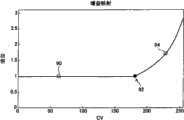
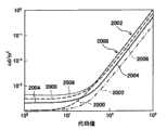
图12是示出随MFP改变的色阶调节模型变化的图表;FIG. 12 is a graph showing changes in the tone scale adjustment model as the MFP is changed;
图13是示出示例性的图像相关的色阶映射方法的流程图;FIG. 13 is a flowchart illustrating an exemplary image-dependent tone scale mapping method;
图14是示出示例性的图像相关的色阶选择实施例的示图;Figure 14 is a diagram illustrating an exemplary image-dependent tone scale selection embodiment;
图15是示出示例性的图像相关的色阶映射计算实施例的示图;Figure 15 is a diagram illustrating an exemplary image-dependent tone scale mapping calculation embodiment;
图16是示出包括源光级调节和图像相关的色阶映射的实施例的流程图;Figure 16 is a flow diagram illustrating an embodiment including source light level adjustment and image dependent tone scale mapping;
图17是示出包括源光级计算器和色阶映射选择器的示例性实施例的示图;17 is a diagram illustrating an exemplary embodiment including a source light level calculator and a tone scale map selector;
图18是示出包括源光级计算器和色阶映射计算器的示例性实施例的示图;18 is a diagram illustrating an exemplary embodiment including a source light level calculator and a tone scale mapping calculator;
图19是示出包括源光级调节和源光级相关的色阶映射的实施例的流程图;Figure 19 is a flow diagram illustrating an embodiment including source light level adjustment and source light level dependent tone scale mapping;
图20是示出包括源光级计算器和源光级相关的色阶计算或选择的实施例的示图;Figure 20 is a diagram illustrating an embodiment including source light level calculator and source light level dependent color scale calculation or selection;
图21是示出原始图像代码值与色阶斜率之间的关系的标绘图的示图;FIG. 21 is a diagram of a plot showing the relationship between the original image code value and the slope of the tone scale;
图22是示出包括单独的色度通道分析的实施例的示图;Figure 22 is a diagram illustrating an embodiment including separate chroma channel analysis;
图23是示出包括对图像处理模块的环境照度输入的实施例的示图;Figure 23 is a diagram illustrating an embodiment including an ambient illuminance input to an image processing module;
图24是示出包括对源光处理模块的环境照度输入的实施例的示图;Figure 24 is a diagram illustrating an embodiment including an ambient illuminance input to a source light processing module;
图25是示出包括对图像处理模块的环境照度输入和器件特性输入的实施例的示图;Figure 25 is a diagram illustrating an embodiment including ambient illuminance input and device characteristic input to an image processing module;
图26是示出包括对图像处理模块和/或源光处理模块以及源光信号后处理器的替代环境照度输入的实施例的示图;Figure 26 is a diagram illustrating an embodiment including an alternative ambient illuminance input to an image processing module and/or a source light processing module and a source light signal post-processor;
图27是示出包括对源光处理模块的环境照度输入的实施例的示图,该源光处理模块将此输入传递至图像处理模块;Figure 27 is a diagram illustrating an embodiment including an ambient illuminance input to a source light processing module which passes this input to an image processing module;
图28是示出包括对图像处理模块的环境照度输入的实施例的示图,该图像处理模块将此输入传递至源光处理模块;Figure 28 is a diagram illustrating an embodiment that includes an ambient illuminance input to an image processing module that passes this input to a source light processing module;
图29是示出包括畸变自适应电源管理的实施例的示图;Figure 29 is a diagram illustrating an embodiment including distortion adaptive power management;
图30是示出包括恒定电源管理的实施例的示图;Figure 30 is a diagram illustrating an embodiment including constant power management;
图31是示出包括自适应电源管理的实施例的示图;Figure 31 is a diagram illustrating an embodiment including adaptive power management;
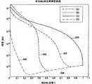
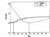
图32A是示出恒定功率模型与恒定畸变模型的功耗的比较的曲线图;32A is a graph showing a comparison of power consumption of a constant power model and a constant distortion model;
图32B是示出恒定功率模型与恒定畸变模型的畸变的比较的曲线图;Figure 32B is a graph showing a comparison of distortion for a constant power model and a constant distortion model;
图33是示出包括畸变自适应电源管理的实施例的示图;Figure 33 is a diagram illustrating an embodiment including distortion adaptive power management;
图34是示出针对示例性视频序列在各个畸变限制下的背光功率电平的曲线图;34 is a graph showing backlight power levels at various distortion limits for an exemplary video sequence;
图35是示出示例性功率/畸变曲线的曲线图;Figure 35 is a graph showing exemplary power/distortion curves;
图36是示出管理与畸变标准相关的功耗的实施例的流程图;Figure 36 is a flowchart illustrating an embodiment of managing power consumption associated with distortion criteria;
图37是示出包括基于畸变标准的源光功率电平选择的实施例的流程图;Figure 37 is a flow diagram illustrating an embodiment including source light power level selection based on distortion criteria;
图38A & B是示出包括说明亮度保持方法的效果的畸变测量值的实施例的流程图;Figures 38A & B are flow diagrams illustrating embodiments including distortion measurements illustrating the effect of the brightness preservation method;
图39是示例性图像的功率/畸变曲线;Figure 39 is a power/distortion curve of an exemplary image;
图40是示出固定畸变的功率曲线图;Figure 40 is a graph of power curves showing fixed distortion;
图41是示出固定畸变的畸变曲线图;Figure 41 is a distortion graph showing fixed distortion;
图42是示例性色阶调节曲线;Figure 42 is an exemplary tone scale adjustment curve;
图43是图42中所示的色阶调节曲线的暗区的放大视图;Figure 43 is an enlarged view of the dark region of the tone scale adjustment curve shown in Figure 42;
图44是另一示例性色阶调节曲线;Figure 44 is another exemplary tone scale adjustment curve;
图45是图44中所示的色阶调节曲线的暗区的放大视图;Figure 45 is an enlarged view of the dark region of the tone scale adjustment curve shown in Figure 44;
图46是示出基于最大彩色通道值的图像代码值调节的图表;Fig. 46 is a graph showing image code value adjustment based on maximum color channel value;
图47是示出基于最大彩色通道代码值的多个彩色通道的图像代码值调节的图表;Figure 47 is a graph showing image code value adjustments for multiple color channels based on maximum color channel code values;
图48是示出基于彩色通道之一的代码值特性的多个彩色通道的图像代码值调节的图表;FIG. 48 is a graph showing image code value adjustments for multiple color channels based on a code value characteristic of one of the color channels;
图49是示出包括接收最大彩色通道值作为输入的色阶发生器的本发明实施例的示图;Figure 49 is a diagram illustrating an embodiment of the invention comprising a tone scale generator receiving as input a maximum color channel value;
图50是示出包括在色阶调节的情况下进行频率分解和彩色通道代码辨别的本发明实施例的示图;Fig. 50 is a diagram illustrating an embodiment of the present invention including frequency decomposition and color channel code discrimination in the case of tone scale adjustment;
图51是示出包括频率分解、彩色通道辨别和色彩保留剪辑的本发明实施例的示图;Figure 51 is a diagram illustrating an embodiment of the present invention including frequency decomposition, color channel discrimination and color preserving clipping;
图52是示出包括基于彩色通道代码值特性的色彩保留剪辑的本发明实施例的示图;Figure 52 is a diagram illustrating an embodiment of the invention including color-preserving clipping based on color channel code value properties;
图53是示出包括低通/高通分频和最大彩色通道代码值的选择的本发明实施例的示图;Figure 53 is a diagram illustrating an embodiment of the invention including selection of low-pass/high-pass crossover and maximum color channel code values;
图54是示出经处理图像和显示模型之间的各种关系的示图;Figure 54 is a diagram illustrating various relationships between processed images and display models;
图55是示例性图像的图像代码值的直方图的曲线图;Figure 55 is a graph of a histogram of image code values for an exemplary image;
图56是与图55的直方图相对应的示例性畸变曲线的曲线图;FIG. 56 is a graph of exemplary distortion curves corresponding to the histogram of FIG. 55;
图57是示出将示例性最优化标准应用于简短的DVD剪辑的结果的曲线图,该曲线图标绘所选背光功率与视频帧数的关系;Figure 57 is a graph showing the results of applying exemplary optimization criteria to a brief DVD clip, plotting selected backlight power versus video frame number;
图58示出针对实际显示的不同对比率的最小MSE畸变背光确定;Figure 58 shows the minimum MSE distortion backlight determination for different contrast ratios of the actual display;
图59是示出示例性面板色调曲线和目标色调曲线的曲线图;FIG. 59 is a graph showing exemplary panel tone curves and target tone curves;
图60是示出针对节电配置的示例性面板色调曲线和目标色调曲线的曲线图;60 is a graph illustrating exemplary panel tone curves and target tone curves for power saving configurations;
图61是示出针对较低黑色电平配置的示例性面板色调曲线和目标色调曲线的曲线图;FIG. 61 is a graph illustrating exemplary panel tone curves and target tone curves for lower black level configurations;
图62是示出针对亮度增强配置的示例性面板色调曲线和目标色调曲线的曲线图;FIG. 62 is a graph illustrating exemplary panel tone curves and target tone curves for a brightness enhancement configuration;
图63是示出针对其中黑色电平被降低且亮度被增强的增强图像配置的示例性面板色调曲线和目标色调曲线的曲线图;63 is a graph illustrating an exemplary panel tone curve and target tone curve for an enhanced image configuration in which black levels are reduced and brightness is enhanced;
图64是示出针对黑色电平改进的一系列示例性目标色调曲线的曲线图;64 is a graph illustrating a series of exemplary target tone curves for black level improvement;
图65是示出针对黑色电平改进和图像亮度增强的一系列示例性目标色调曲线的曲线图;65 is a graph illustrating a series of exemplary target tone curves for black level improvement and image brightness enhancement;
图66是示出包括目标色调曲线确定和畸变相关背光选择的示例性实施例的图表;Figure 66 is a graph illustrating an exemplary embodiment including target tone curve determination and distortion dependent backlight selection;
图67是示出包括性能目标相关参数选择、目标色调曲线确定和背光选择的示例性实施例的图表;Figure 67 is a chart illustrating an exemplary embodiment including performance target related parameter selection, target tone curve determination, and backlight selection;
图68是示出包括性能目标相关的目标色调曲线确定和背光选择的示例性实施例的图表;Figure 68 is a graph illustrating an exemplary embodiment of target tone curve determination and backlight selection including performance target correlation;
图69是示出包括性能目标相关和图像相关的目标色调曲线确定和背光选择的示例性实施例的图表;Figure 69 is a graph illustrating an exemplary embodiment of target tone curve determination and backlight selection including performance target dependent and image dependent;
图70是示出包括在位深扩展的情况下进行频率分解和色阶处理的示例性实施例的图表;FIG. 70 is a diagram illustrating an exemplary embodiment including frequency decomposition and tone scale processing with bit depth extension;
图71是示出包括频率分解和色彩增强的示例性实施例的图表;FIG. 71 is a diagram illustrating an exemplary embodiment including frequency decomposition and color enhancement;
图72是示出包括色彩增强、背光选择和高通增益处理的示例性实施例的图表;Figure 72 is a chart illustrating an exemplary embodiment including color enhancement, backlight selection, and high-pass gain processing;
图73是示出包括色彩增强、直方图生成、色阶处理和背光选择的示例性实施例的图表;Figure 73 is a diagram illustrating an exemplary embodiment including color enhancement, histogram generation, tone scale processing, and backlight selection;
图74是示出包括肤色检测和肤色映射细化的示例性实施例的图表;Figure 74 is a diagram illustrating an exemplary embodiment including skin tone detection and skin tone map refinement;
图75是示出包括色彩增强和位深扩展的示例性实施例的图表;Figure 75 is a diagram illustrating an exemplary embodiment including color enhancement and bit depth extension;
图76是示出包括色彩增强、色阶处理和位深扩展的示例性实施例的图表;FIG. 76 is a diagram illustrating an exemplary embodiment including color enhancement, tone scale processing, and bit depth extension;
图77是示出包括色彩增强的示例性实施例的图表;Figure 77 is a diagram illustrating an exemplary embodiment including color enhancement;
图78是示出包括色彩增强和位深扩展的示例性实施例的图表;Figure 78 is a diagram illustrating an exemplary embodiment including color enhancement and bit depth extension;
图79是示出目标输出曲线和多个面板或显示输出曲线的曲线图;FIG. 79 is a graph showing a target output curve and multiple panel or display output curves;
图80是示出图79的目标和显示输出曲线的误差向量曲线的曲线图;Figure 80 is a graph showing the target and error vector curves of the displayed output curves of Figure 79;
图81是示出直方图加权误差曲线的曲线图;Figure 81 is a graph showing a histogram weighted error curve;
图82是示出包括基于直方图加权误差的源光照度级选择的本发明的示例性实施例的图表;Figure 82 is a graph illustrating an exemplary embodiment of the present invention including source light illumination level selection based on histogram weighted error;
图83是示出包括基于直方图加权误差的源光照度级选择的本发明的替代示例性实施例的图表;Figure 83 is a graph illustrating an alternative exemplary embodiment of the present invention including source light illumination level selection based on histogram weighted errors;
图84是示出包括场景剪切检测器的示例性系统的图表;84 is a diagram illustrating an exemplary system including a scene cut detector;
图85是示出包括场景剪切检测器和图像补偿模块的示例性系统的图表;85 is a diagram illustrating an exemplary system including a scene cut detector and an image compensation module;
图86是示出包括场景剪切检测器和直方图缓冲器的示例性系统的图表;86 is a diagram illustrating an exemplary system including a scene cut detector and a histogram buffer;
图87是示出包括场景剪切检测器和对该场景剪切检测器作出响应的时间滤波器的示例性系统的图表;87 is a diagram illustrating an exemplary system including a scene cut detector and a temporal filter responsive to the scene cut detector;
图88是示出其中滤波检测基于场景剪切检测的示例性方法的图表;88 is a diagram illustrating an exemplary method in which filter detection is based on scene cut detection;
图89是示出其中比较各帧以检测场景剪切的示例性方法的图表;89 is a diagram illustrating an exemplary method in which frames are compared to detect scene cuts;
图90是示出在没有滤波器的情况下的背光响应的图表;Figure 90 is a graph showing backlight response without a filter;
图91是示出典型的时间对比灵敏度函数的曲线图;Figure 91 is a graph showing a typical time versus sensitivity function;
图92是示出示例性滤波器的响应的曲线图;Figure 92 is a graph showing the response of an exemplary filter;
图93是示出经滤波和未经滤波的背光响应的曲线图;Figure 93 is a graph showing filtered and unfiltered backlight response;
图94是示出场景剪切上的滤波响应的曲线图;Figure 94 is a graph showing filter response on scene cuts;
图95是示出场景剪切上的未经滤波响应以及第一经滤波响应和第二经滤波响应的曲线图;Figure 95 is a graph showing the unfiltered response and the first and second filtered responses on a scene cut;
图95是示出未经滤波的、经滤波的、以及经场景剪切滤波的响应的曲线图;Figure 95 is a graph showing unfiltered, filtered, and scene cut filtered responses;
图96是示出包括直方图缓冲器、时间滤波器和Y增益补偿的实施例的系统图;Figure 96 is a system diagram illustrating an embodiment including a histogram buffer, temporal filter, and Y gain compensation;
图97是示出各种示例性Y增益曲线的曲线图;FIG. 97 is a graph showing various exemplary Y gain curves;
图98是示出示例性显示模型的曲线图;Figure 98 is a graph illustrating an exemplary display model;
图99是示出示例性显示误差向量曲线的曲线图;Figure 99 is a graph showing an exemplary display error vector curve;
图100是示出示例性图像直方图的曲线的曲线图;FIG. 100 is a graph showing the curves of an exemplary image histogram;
图101是示出示例性图像畸变与背光级的关系曲线的曲线图;FIG. 101 is a graph illustrating exemplary image distortion versus backlight level;
图102是示出不同畸变度量的比较的曲线图;Figure 102 is a graph showing a comparison of different distortion metrics;
图103是示出包括场景剪切检测和图像补偿的示例性系统的示图;Figure 103 is a diagram illustrating an exemplary system including scene cut detection and image compensation;
图104是示出包括用以确定场景剪切的图像分析和响应场景剪切的畸变计算的示例性方法的示图;104 is a diagram illustrating an example method including image analysis to determine scene cuts and distortion calculations in response to scene cuts;
图105是示出包括图像特性映射模块的示例性系统的示图;Figure 105 is a diagram illustrating an exemplary system including an image property mapping module;
图106是示出包括具有手动用户映射选择输入的图像特性映射模块的示例性系统的示图;106 is a diagram illustrating an example system including an image property mapping module with manual user mapping selection input;
图107是示出包括具有环境光传感器输入的图像特性映射模块的示例性系统的示图;107 is a diagram illustrating an example system including an image characteristic mapping module with ambient light sensor input;
图108是示出包括具有用户亮度选择输入的图像特性映射模块的示例性系统的示图;108 is a diagram illustrating an example system including an image property mapping module with user brightness selection input;
图109是示出包括具有用户亮度选择输入的图像特性映射模块和响应于用户亮度选择的时间滤波器的示例性系统的示图;109 is a diagram illustrating an example system including an image characteristic mapping module with user brightness selection input and a temporal filter responsive to user brightness selection;
图110是示出包括具有用户亮度选择输入、环境传感器输入和手动映射选择的图像特性映射模块的示例性系统的示图;110 is a diagram illustrating an example system including an image property mapping module with user brightness selection input, environmental sensor input, and manual mapping selection;
图111是示出包括涉及图像直方图数据的图像特性映射模块的示例性系统的示图;Figure 111 is a diagram illustrating an example system including an image property mapping module involving image histogram data;
图112是示出示例性直方图转换方法的示图;FIG. 112 is a diagram illustrating an exemplary histogram conversion method;
图113是示出用于直方图生成和转换的示例性方法的示图;Figure 113 is a diagram illustrating an exemplary method for histogram generation and conversion;
图114是示出包括直方图转换并用于映射和畸变模块的示例性实施例的示图;Figure 114 is a diagram illustrating an exemplary embodiment including histogram transformation and used for mapping and distortion modules;
图115是示出示例性直方图动态范围转换的示图;以及Figure 115 is a diagram illustrating exemplary histogram dynamic range conversion; and
图116是示出包括直方图转换和动态范围转换的示例性实施例的示图。FIG. 116 is a diagram illustrating an exemplary embodiment including histogram conversion and dynamic range conversion.
示例性实施例的详细描述Detailed Description of Exemplary Embodiments
参照附图本发明诸实施例将得到最佳的理解,在全部附图中相同的部件由相同的附图标记标示。以上所列附图被明确地纳入为本说明书的一部分。Embodiments of the invention will be best understood by reference to the drawings, in which like parts are designated by like reference numerals throughout. The drawings listed above are expressly incorporated as part of this specification.
将容易理解,如附图中所一般描述和例示地,本发明的组件将以各种各样的不同配置进行排列和设计。因此,本发明的方法和系统的实施例的以下更详细描述不旨在限制本发明的范围,而仅仅表示本发明的当前优选实施例。It will be readily understood that the components of the present invention may be arranged and designed in a wide variety of different configurations as generally described and illustrated in the drawings. Accordingly, the following more detailed description of embodiments of the method and system of the present invention is not intended to limit the scope of the invention but is merely representative of the presently preferred embodiments of the invention.
本发明诸实施例的要素可用硬件、固件和/或软件实现。尽管本文中所公开的示例性实施例可能仅描述这些形式之一,但可以理解本领域技术人员将能够以这些形式的任一种来实现这些要素且落在本发明的范围之内。Elements of embodiments of the invention may be implemented in hardware, firmware and/or software. Although the exemplary embodiments disclosed herein may only describe one of these forms, it is to be understood that a person skilled in the art would be able to implement the elements in any of these forms and remain within the scope of the invention.
使用诸如LC调制器的光阀调制器和其它调制器的显示设备可以是反射性的,其中光被照射至正面(面对观看者)并且在通过调制面板层之后向观看者反射回。显示设备也可以是透射性的,其中光被照射至调制面板层的背面,且被允许通过调制层照向观看者。一些显示设备也可以是透射反射性的,即反射性和透射性的组合,其中光可从背面向正面地通过调制层,同时来自另一源的光在从调制层的正面进入之后反射。在这些情形的任一个中,调制层中的元件(诸如各个LC元件)可控制像素的感知亮度。Display devices using light valve modulators such as LC modulators and other modulators can be reflective, where light is shone onto the front side (facing the viewer) and reflected back toward the viewer after passing through the modulating panel layer. The display device may also be transmissive, where light is shone onto the backside of the modulating panel layer and allowed to pass through the modulating layer towards the viewer. Some display devices can also be transreflective, ie a combination of reflectivity and transmissivity, where light can pass through the modulating layer from the back to the front, while light from another source is reflected after entering from the front of the modulating layer. In either of these cases, elements in the modulation layer, such as individual LC elements, can control the perceived brightness of the pixel.
在背光、前光和侧光显示器中,光源可以是一串荧光管、LED阵列或某些其它源。一旦显示器大于约18″的典型尺寸,则该设备的大部分功耗是由光源引起的。对于特定应用,并且在特定市场中,功耗的降低是重要的。然而,功率降低意味着光源的光通量的减少,由此意味着显示器最大亮度的降低。In backlit, frontlit, and edgelit displays, the light source may be a string of fluorescent tubes, an array of LEDs, or some other source. Once the display is larger than the typical size of about 18", most of the power consumption of the device is caused by the light source. For certain applications, and in certain markets, the reduction of power consumption is important. However, the power reduction means that the power consumption of the light source A reduction in luminous flux, thus means a reduction in the maximum brightness of the display.
使电流γ校正光阀调制器的灰度电平代码值、CV、光源级即L源和输出光能级L输出相关的基本方程是:The basic equation that correlates the gray level code value, CV, light source level i.e. Lsource and output light energy level Loutput of the current γ corrected light valve modulator is:
方程1
L输出=L源*g(CV+暗)γ+环境Loutput = Lsource * g (CV + dark)γ + environment
其中g是校准增益,暗是光阀的暗电平,且环境是从室内条件命中显示器的光。根据此方程,可看出减少背光光源x%也将所输出光减少x%。where g is the calibration gain, dark is the dark level of the light valve, and ambient is the light hitting the display from room conditions. From this equation, it can be seen that reducing the backlight source by x% also reduces the output light by x%.
可通过改变光阀的调制值,具体而言增大它们来补偿光源级的降低。实际上,低于(1-x%)的任何光能级可准确再现,而高于(1-x%)的任何光能级在没有附加光源或光源强度不增加的情况下不能再现。The decrease in light source level can be compensated by changing the modulation values of the light valves, in particular increasing them. In fact, any light power level below (1-x%) can be accurately reproduced, while any light power level above (1-x%) cannot be reproduced without additional or increased light source intensity.
设置从原始和简约源输出的光给出基本代码值校正,其可用来针对x%的降低(假设暗电平和环境光为0)校正代码值:Setting the light output from the original and parsimonious sources gives the base code value correction which can be used to correct the code value for x% reduction (assuming dark level and ambient light are 0):
方程2
L输出=L源*g(CV)γ=L简约*g(CV升压)γLoutput = Lsource * g (CV)γ = Lsimple * g (CVboost )γ
方程3
CV升压=CV*(L源/L简约)1/γ=CV*(1/x%)1/γ.CVboost =CV*(Lsource /Lreduction )1/γ =CV*(1/x%)1/γ .
图2A示出此调节。在图2A和2B中,原始显示值对应于沿线12的点。当背光或光源被置于节能模式且该光源照度降低时,显示代码值需要被增大以使光阀能抵消光源照度的降低。这些增大值与沿线14的点相一致。然而,此调节导致代码值18高于显示器所能够产生的代码值(例如对8位显示器而言为255)。因此,这些值最终被削波20,如图2B所示。以此方式调节的图像会遭受高亮模糊、伪外观、以及一般低质量的问题。Figure 2A illustrates this adjustment. In FIGS. 2A and 2B , the raw display values correspond to points along
使用此简单调节模型,低于削波点15的代码值(在此示例性实施例中为输入代码值230)将以与用全功率光源产生的辉度级相等的辉度级、但以降低的源光照明模式显示。该相同辉度以较低功率产生,从而导致节能。如果图像的代码值集合受限于低于削波点15的范围,则节能模式可对用户透明地操作。不幸地是,当值超过削波点15时,辉度降低且细节丢失。本发明诸实施例提供可改变LCD或光阀代码值以提供增强亮度(或者在节能模式下不减弱亮度)、同时减少会在辉度范围高端发生的削波伪像的一种算法。Using this simple tuning model, code values below the clipping point of 15 (in this exemplary embodiment, the input code value 230) will produce at a luminance level equal to that produced with a full power source, but at a reduced The lighting mode of the source light is displayed. This same luminance is produced with lower power, resulting in energy savings. If the image's set of code values is restricted to a range below the
本发明的一些实施例通过针对相当大范围的值使以低功率显示的图像亮度与以全功率显示的图像辉度相匹配,可消除与降低显示光源功率相关联的亮度降低。在这些实施例中,源光或背光功率的将输出辉度除以特定因子的降低由图像数据增大倒数因子来补偿。Some embodiments of the present invention can eliminate the brightness reduction associated with reducing display light source power by matching image brightness displayed at low power to image brightness displayed at full power for a substantial range of values. In these embodiments, the reduction in source light or backlight power dividing the output luminance by a certain factor is compensated for by increasing the image data by an inverse factor.
忽略动态范围约束,在全功率和降低功率下显示的图像可以是相同的,因为除分(对于降低的光源亮度)和倍增(对于增大的代码值)在相当大范围上实质上是抵消的。在图像数据的倍增(对于代码值增大)超过显示的最大值的任何时候,动态范围限制可引起削波伪像。动态范围约束所引起的削波伪像可通过滚降在代码值上端的该增大来消除或减少。此滚降可在最大保真点(MFP)开始,超过该最大保真点则辉度不再与原始辉度相匹配。Neglecting dynamic range constraints, the displayed image at full and reduced power can be the same, since division (for reduced light source brightness) and multiplication (for increased code values) substantially cancels out over a considerable range . Dynamic range limitations can cause clipping artifacts anytime the multiplication of image data (for code value increases) exceeds the displayed maximum value. Clipping artifacts caused by dynamic range constraints can be eliminated or reduced by rolling off this increase above the code value. This roll-off may start at the maximum fidelity point (MFP), beyond which the luminance no longer matches the original luminance.
在本发明的一些实施例中,可执行以下步骤来补偿光源照度降低或虚拟降低以便于图像增强:In some embodiments of the invention, the following steps may be performed to compensate for light source illumination reduction or virtual reduction for image enhancement:
1)源光(背光)降低水平根据辉度减弱百分比来确定;1) The source light (backlight) reduction level is determined according to the brightness reduction percentage;
2)确定最大保真点(MFP),在该MFP处发生从匹配功率降低输出到全功率输出的滚降。2) Determine the maximum fidelity point (MFP) at which the roll-off from matched power reduced output to full power output occurs.
3)确定补偿色阶算子;3) Determine the compensation color scale operator;
a.在低于MFP之处,增大色阶以补偿显示辉度的减弱;a. At places below the MFP, increase the color scale to compensate for the weakening of the display brightness;
b.在高于MFP之处,逐渐地滚降色阶(在一些实施例中,保持导数连续);b. Gradually roll off the color scale above the MFP (in some embodiments, keep the derivative continuous);
4)将色阶映射算子应用于图像;以及4) applying a color scale mapping operator to the image; and
5)发送给显示器。5) Send to the display.
这些实施例的主要优点是可在仅对狭窄类别的图像有小改变的情况下实现节能。(差异仅在MFP之上出现,且由峰值亮度减弱和一些亮度细节的损失构成)。MFP之下的图像值能以节能模式用与全功率模式相同的辉度显示,从而使得图像的这些区域不能与全功率模式作区分。The main advantage of these embodiments is that power savings can be achieved with only small changes to narrow classes of images. (The difference is only seen above the MFP and consists of a reduction in peak brightness and some loss of brightness detail). Image values below the MFP can be displayed in power saving mode with the same intensity as in full power mode, making these areas of the image indistinguishable from full power mode.
本发明的一些实施例可使用取决于功率降低和显示γ、并且与图像数据无关的色阶映射。这些实施例可提供两个优点。首先可能因不同地处理多个帧而产生的闪烁伪像没有产生,其次该算法具有极低的实现复杂性。在一些实施例中,可使用离线色阶设计和在线色阶映射。高亮中的削波可通过指定MFP来控制。Some embodiments of the invention may use a tone scale map that depends on power reduction and display gamma, and is independent of image data. These embodiments may provide two advantages. Firstly, flickering artifacts that may arise from processing multiple frames differently are not produced, and secondly, the algorithm has extremely low implementation complexity. In some embodiments, offline tone scale design and online tone scale mapping may be used. Clipping in highlights can be controlled by specifying the MFP.
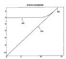
本发明诸实施例的一些方面可相关于图3进行描述。图3是示出对于若干情形的图像代码值与辉度的关系的曲线图。示为虚线的第一曲线32表示以100%功率运行的光源的原始代码值。示为点划线的第二曲线30表示当光源以全功率的80%运行时原始代码值的辉度。示为虚线的第三曲线36表示当代码值被增大以匹配光源以全功率的80%操作时以100%光源照度提供的辉度之时的辉度。示为实线的第四曲线34表示增大的数据,但其中滚降曲线降低了数据高端上削波的效果。Some aspects of embodiments of the invention may be described with respect to FIG. 3 . Figure 3 is a graph showing image code values versus luminance for several cases. A
在如图3所示的该示例性实施例中,使用代码值180处的MFP 35。注意,在低于代码值180处,增大曲线34匹配原始100%功率显示的辉度输出32。在180以上,增大曲线平滑过渡到80%显示上所允许的最大输出。该平滑性减少了削波和量化伪像。在一些实施例中,色阶函数可分段定义,以在由MFP 35给出的过渡点处平滑匹配。在MFP 35之下,可使用增大的色阶函数。在MFP 35之上,曲线平滑拟合至该MFP处增大色阶曲线的终点,并拟合至最大代码值[255]处的终点37。在一些实施例中,该曲线的斜率在MFP 35处与增大色阶曲线/直线的斜率相匹配。这可通过使该MFP处直线和曲线函数的导数相等而使MFP之下的直线斜率与MFP之上的曲线斜率相匹配、并且使该点处直线和曲线函数的值相等来实现。对该曲线函数的另一约束可以是它被迫使通过最大值点[255,255]37。在一些实施例中,曲线的斜率在最大值点37处可被设置成0。在一些实施例中,180的MFP值可对应于20%的光源功率降低。In this exemplary embodiment as shown in FIG. 3, the
在本发明的一些实施例中,色阶曲线可由与最大保真点(MFP)之下的增益g的线性关系来定义。该色阶可在该MFP之上进一步定义,以使该曲线及其一阶导数在MFP处连续。该连续性表示关于色阶函数的以下形式:In some embodiments of the invention, the tone scale curve may be defined by a linear relationship with the gain g below the maximum fidelity point (MFP). The color scale can be further defined above the MFP such that the curve and its first derivative are continuous at the MFP. This continuity expresses the following form with respect to the color scale function:
C=g·MFPC=g·MFP
B=gB=g
方程4
该增益可通过显示γ和亮度减弱比确定如下:This gain can be determined by displaying γ and the brightness reduction ratio as follows:
方程5

在一些实施例中,该MFP值可通过手动平衡高亮细节保持和绝对亮度保持来调谐。In some embodiments, this MFP value can be tuned by manually balancing highlight detail preservation with absolute brightness preservation.
MFP可通过施加斜率在最大点应当为零的约束来确定。这意味着:MFP can be determined by imposing a constraint that the slope should be zero at the point of maximum. this means:
方程6


在一些示例性实施例中,以下方程可用来根据一示例性实施例分别计算简单增大数据的代码值、具有削波的增大数据、以及经校正数据。In some exemplary embodiments, the following equations may be used to calculate code values for simple augmented data, augmented data with clipping, and corrected data, respectively, according to an exemplary embodiment.
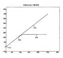
方程7Equation 7
色阶增大(cv)=(1/x)1/γ·cvColor scaleincrease (cv) = (1/x)1/γ cv


系数A、B和C可被选择成给出MFP处的平滑拟合以使曲线通过该点[255,255]。这些函数的曲线在图4中示出。The coefficients A, B and C can be chosen to give a smooth fit at the MFP such that the curve passes through this point [255, 255]. The curves of these functions are shown in FIG. 4 .
图4是原始代码值与经调节代码值之间关系的曲线图。原始代码值被示为沿原始数据线40的点,该数据线示出在值是原始的且没有进行调节时经调节值与原始值之间的1∶1关系。根据本发明诸实施例,这些值可被增大或调节以表示更高的辉度级。根据以上“色阶增大”方程的简单增大过程可产生沿增大线42的值。因为这些值的显示将导致削波,如线46上图形地和以上“色阶削波”方程中数学地所示,调节可从最大保真点45沿曲线44逐渐过渡至最大值点47。在一些实施例中,此关系可在以上“经校正色阶”方程中数学地描述。Figure 4 is a graph of the relationship between original code values and adjusted code values. The original code values are shown as points along the
使用这些概念,由具有以100%功率运行的光源的显示器所表示的辉度值可由具有以低功率电平运行的光源的显示器来表示。这通过色阶的增大来实现,这实质上进一步打开了光阀以补偿光源照度的损失。然而,在整个代码值范围上简单应用此增大导致该范围高端上的削波伪像。为防止或减少这些伪像,色阶函数可被平滑滚降。此滚降可受到MFP参数控制。大的MFP值在宽间隔上给出辉度匹配,但增加了代码值高端上的可视量化/削波伪像。Using these concepts, a luminance value represented by a display with a light source running at 100% power can be represented by a display with a light source running at a low power level. This is achieved through an increase in color scale, which essentially opens the light valve further to compensate for the loss of light source illumination. However, simply applying this increase over the entire range of code values results in clipping artifacts on the high end of the range. To prevent or reduce these artifacts, the tone scale function can be rolled off smoothly. This roll-off can be controlled by MFP parameters. Large MFP values give luminance matching over wide intervals, but increase visible quantization/clipping artifacts on the high end of code values.
本发明诸实施例可通过调节代码值来操作。在简单的γ显示模型中,代码值的缩放给出具有不同缩放因子的辉度值的缩放。为了确定在更为真实的显示模型中此关系是否保持,可考虑γ偏移增益-杂光(GOG-F)模型。缩放背光功率对应于线性约简方程,其中百分比p被施加于显示的输出而非环境光。已观察到,将增益缩减因子p等效于使增益不作修改,并将数据、代码值和偏置缩放由显示γ确定的因子。在数学上,如果经适当修改,倍乘因子可被拖入功率函数。该经修改因子可缩放代码值和偏置两者。Embodiments of the invention may operate by adjusting code values. In a simple gamma display model, scaling of code values gives scaling of luminance values with different scaling factors. To determine whether this relationship holds in a more realistic display model, the gamma-offset gain-flare (GOG-F) model can be considered. Scaling the backlight power corresponds to a linear reduction equation, where the percentage p is applied to the output of the display rather than the ambient light. It has been observed that reducing the gain by a factor p is equivalent to leaving the gain unmodified and scaling the data, code values and bias by a factor determined by display γ. Mathematically, multiplication factors can be dragged into the power function if modified appropriately. This modified factor can scale both code values and offsets.
方程8 GOG-F模型
L=G·(CV+暗)γ+环境L=G·(CV+dark)γ +environment
方程9线性辉度降低Equation 9 Linear Luminance Reduction
L线性约简=p·G·(CV+暗)γ+环境Llinear reduction = p G (CV + dark)γ + environment
L线性约简=G·(p1/γ·(CV+暗))γ+环境Llinear reduction = G (p1/γ (CV+dark))γ + environment
L线性约简=G·(p1/γ·CV+p1/γ·暗)γ+环境Llinear reduction = G (p1/γ CV+p1/γ dark)γ + environment
方程10代码值减小
LCV约简=G·(p1/γ·CV+暗)γ+环境LCV reduction = G (p1/γ CV + dark)γ + environment
本发明的一些实施例可参照图5进行描述。在这些实施例中,可在图像处理之前离线地设计或计算色阶调节,或者在对图像进行处理时可在线地设计或计算该调节。不考虑操作的定时,色阶调节56可基于显示γ50、效率因子52和最大保真点(MFP)54的至少之一来设计或计算。这些因子可在色阶设计过程56中处理以产生色阶调节模型58。色阶调节模型可采取算法、查找表(LUT)或可应用于图像数据的某其它模型的形式。Some embodiments of the invention may be described with reference to FIG. 5 . In these embodiments, the tone scale adjustment may be designed or calculated offline prior to image processing, or it may be designed or calculated online while the image is being processed. Regardless of the timing of operation,
一旦已创建了调节模型58,它就可应用于图像数据。该调节模型的应用可参照图6进行描述。在这些实施例中,图像被输入(62)且色阶调节模型58被应用(64)于该图像以调节图像代码值。此过程产生可被发送至显示器的输出图像66。色阶调节的应用64通常是一在线过程,但可在条件允许时在图像显示之前进行。Once the
本发明的一些实施例包括用于增强在利用发光像素调制器的诸如LED显示器、等离子显示器和其它类型显示器的显示器上显示的图像的系统和方法。这些相同的系统和方法可用来增强在具有以全功率模式或其它方式运行的光源的利用光阀像素调制器的显示器上显示的图像。Some embodiments of the invention include systems and methods for enhancing images displayed on displays such as LED displays, plasma displays, and other types of displays that utilize light-emitting pixel modulators. These same systems and methods can be used to enhance images displayed on displays utilizing light valve pixel modulators with light sources operating in full power mode or otherwise.
这些实施例与前述实施例相似地工作,但是这些实施例并不对降低的光源照度作补偿,而是像光源已减弱一样简单地增强一像素范围的辉度。以此方式,图像的整体亮度得以改进。These embodiments work similarly to the previous embodiments, but instead of compensating for reduced light source illuminance, these embodiments simply boost a pixel-wide luminance as if the light source had been reduced. In this way, the overall brightness of the image is improved.
在这些实施例中,在相当大范围的值上原始代码值被增大。对于其它实施例,此代码值调节可如上所述地实现,不同之处在于不会有实际的光源照度降低发生。因此,图像亮度在宽泛范围的代码值上显著增强。In these embodiments, the original code value is augmented over a considerable range of values. For other embodiments, this code value adjustment may be accomplished as described above, except that no actual reduction in light source illumination occurs. Consequently, image brightness is significantly enhanced over a wide range of code values.
这些实施例的一部分也可参照图3进行说明。在这些实施例中,原始图像的代码值被示为沿曲线30的点。这些值可被增大或调节成具有更高辉度级的值。这些增大的值可被表示为沿曲线34的点,其从零点33延伸至最大保真点35、然后逐渐过渡至最大值点37。Some of these embodiments are also described with reference to FIG. 3 . In these embodiments, the code values of the original image are shown as points along the
本发明的一些实施例包括反锐化掩模(unsharp masking)处理。在这些实施例的一部分中,反锐化掩模可使用空间变化增益。此增益可根据图像值和经修改色阶曲线的斜率来确定。在一些实施例中,增益阵列的使用使得甚至在图像亮度由于对显示功率的限制而不能倍增时也能匹配图像对比度。Some embodiments of the invention include an unsharp masking process. In some of these embodiments, the unsharp mask may use a spatially varying gain. This gain can be determined from the image values and the slope of the modified tone scale curve. In some embodiments, the use of a gain array enables matching of image contrast even when image brightness cannot be multiplied due to limitations on display power.
本发明的一些实施例可采取以下处理步骤:Some embodiments of the invention may take the following processing steps:
1.计算色阶调节模型;1. Calculate the color scale adjustment model;
2.计算高通图像;2. Compute Qualcomm image;
3.计算增益阵列;3. Calculate the gain array;
4.按增益加权高通图像;4. Weight the high-pass image by gain;
5.将低通图像与加权高通图像求和;以及5. Summing the low-pass image with the weighted high-pass image; and
6.发送给显示器。6. Send to the display.
本发明的其它实施例可采取以下处理步骤:Other embodiments of the invention may take the following processing steps:
1.计算色阶调节模型;1. Calculate the color scale adjustment model;
2.计算低通图像;2. Calculate the low-pass image;
3.将高通图像计算为图像与低通图像之间的差异;3. Calculate the high-pass image as the difference between the image and the low-pass image;
4.利用图像值和经修改色阶曲线的斜率来计算增益阵列;4. Compute the gain array using the image values and the slope of the modified tone scale curve;
5.按增益加权高通图像;5. Weight the high-pass image by gain;
6.将低通图像与加权高通图像求和;以及6. Summing the low-pass image with the weighted high-pass image; and
7.发送给功率降低的显示器。7. Send to the display with reduced power.
使用本发明的一些实施例,可在仅对狭窄类别的图像有小改变的情况下实现节能。(差异仅在MFP之上出现,且由峰值亮度减弱和一些亮度细节的损失组成。)MFP之下的图像值能以节能模式用与全功率模式相同的辉度显示,从而使得图像的这些区域不能与全功率模式作区分。本发明的其它实施例通过减少亮度细节的损失来改善此性能。Using some embodiments of the invention, power savings can be achieved with only small changes to narrow classes of images. (The difference appears only above the MFP, and consists of a reduction in peak luminance and a loss of some luminance detail.) Image values below the MFP can be displayed with the same luminance in power-saving mode as in full-power mode, making these areas of the image Cannot be distinguished from full power mode. Other embodiments of the invention improve this performance by reducing the loss of luminance detail.
这些实施例可包括在空间上改变反锐化掩模以保持亮度细节。与其它实施例相同,可使用在线和离线组件。在一些实施例中,离线组件可通过计算增益映射以及色阶函数来扩展。该增益映射可基于图像值来指定要应用的反锐化滤波器。增益映射值可使用色阶函数的斜率来确定。在一些实施例中,特定点“P”处的增益映射值可被计算为MFP之下色阶函数的斜率与点“P”处的色阶函数的斜率之比。在一些实施例中,色阶函数在MFP之下是线性的,因此增益在MFP之下为1。These embodiments may include spatially varying the unsharp mask to preserve luminance detail. As with other embodiments, both online and offline components can be used. In some embodiments, the offline component can be extended by computing a gain map as well as a tone scale function. The gain map may specify an unsharp filter to apply based on image values. Gain map values may be determined using the slope of the tone scale function. In some embodiments, the gain map value at a particular point "P" may be calculated as the ratio of the slope of the tone scale function below the MFP to the slope of the tone scale function at point "P". In some embodiments, the tone scale function is linear below the MFP, so the gain is 1 below the MFP.
本发明的一些实施例可参照图7进行描述。在这些实施例中,可在图像处理之前离线地设计或计算色阶调节,或者在对图像进行处理时可在线地设计或计算该调节。不考虑操作的定时,色阶调节76可基于显示γ70、效率因子72和最大保真点(MFP)74的至少之一来设计或计算。这些因子可在色阶设计过程76中处理以产生色阶调节模型78。色阶调节模型可采取算法、查找表(LUT)或可如上相关于其它实施例所述地应用于图像数据的某些其它模型的形式。在这些实施例中,还计算(75)单独的增益映射77。该增益映射77可应用于特定的图像细分部分,诸如频率范围。在一些实施例中,增益映射可应用于图像的分频部分。在一些实施例中,增益映射可应用于高通图像细分部分。它也可应用于特定的图像频率范围或其它图像细分部分。Some embodiments of the invention may be described with reference to FIG. 7 . In these embodiments, the tone scale adjustment may be designed or calculated offline prior to image processing, or it may be designed or calculated online while the image is being processed. Regardless of the timing of operation, tone scale adjustment 76 may be designed or calculated based on at least one of
示例性色阶调节模型可参照图8进行描述。在这些示例性实施例中,函数过渡点(FTP)84(类似于光源减弱补偿实施例中使用的MFP)被选择,且增益函数被选择成向低于FTP 84的值提供第一增益关系82。在一些实施例中,该第一增益关系可以是线性关系,但其它关系和函数可用来将代码值转变成增强代码值。在FTP 84之上,可使用第二增益关系86。该第二增益关系86可以是将FTP 84与最大值点88连结在一起的函数。在一些实施例中,该第二增益关系86可在FTP 84处匹配第一增益关系82的值和斜率,并通过最大值点88。如以上相关于其它实施例描述的其它关系以及另外的关系也可用作第二增益关系86。An exemplary tone scale adjustment model may be described with reference to FIG. 8 . In these exemplary embodiments, a function transition point (FTP) 84 (similar to the MFP used in light source fade compensation embodiments) is selected, and the gain function is selected to provide a
在一些实施例中,增益映射77可相关于如图8所示的色阶调节模型来计算。示例性增益映射77可相关于图9进行描述。在这些实施例中,增益映射函数与色阶调节模型78相关,其作为色阶调节模型的斜率的函数。在一些实施例中,特定码值上增益映射函数的值根据色阶调节模型在FTP之下的任一代码值处的斜率与色阶调节模型在该特定代码值处的斜率之比来确定。在一些实施例中,此关系可用方程11来数学表达;In some embodiments,
方程11

在这些实施例中,在FTP之下的增益映射函数等于1,在该FTP处色阶调节模型产生线性上升。对于FTP之上的代码值,增益映射函数随着色阶调节模型的斜率递减而快速增大。此增益映射函数的急剧增大增强了其所应用的图像部分的对比度。In these embodiments, the gain mapping function is equal to 1 below the FTP at which the tone scale scaling model produces a linear ramp. For code values above FTP, the gain mapping function increases rapidly with decreasing slope of the tone scale adjustment model. A sharp increase of this gain mapping function enhances the contrast of the image portion to which it is applied.
图8所示的示例性色阶调节因子和图9所示的示例性增益映射函数使用80%的显示百分比(源光减弱)、2.2的显示γ和180的最大保真度点来计算。The example tone scale adjustment factor shown in FIG. 8 and the example gain map function shown in FIG. 9 were calculated using a display percentage (source light attenuation) of 80%, a display gamma of 2.2, and a maximum fidelity point of 180.
在本发明的一些实施例中,可在应用色阶调节模型之后应用反锐化掩模操作。在这些实施例中,用反锐化掩模技术来减少伪像。In some embodiments of the invention, the unsharp masking operation may be applied after applying the tone scale adjustment model. In these embodiments, an unsharp masking technique is used to reduce artifacts.
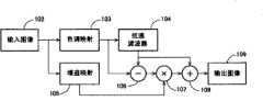
本发明的一些实施例可参照图10进行描述。在这些实施例中,原始图像102被输入且色阶调节模型103被应用于该图像。该原始图像102还被用作产生增益映射的增益映射处理105的输入。色阶调节图像然后通过低通滤波器104处理,从而产生低通调节图像。该低通调节图像然后从色阶调节图像减去(106)以产生高通调节图像。此高通调节图像然后乘以(107)增益映射中的适当值以提供增益调节高通图像,该增益调节高通图像然后加至(108)已用色阶调节模型调节的低通调节图像。此相加产生具有增强亮度和改善高频对比度的输出图像109。Some embodiments of the invention may be described with reference to FIG. 10 . In these embodiments, an
在这些实施例的一部分中,对于图像的每个像素的每个分量,增益值根据该像素处的增益映射和图像值来确定。在应用该色阶调节模型之前,原始图像102可用来确定增益。高通图像的每个像素的每个分量在加回至低通图像之前还可被缩放相应增益值。在增益映射函数为1的点处,反锐化掩模操作没有修改图像值。在增益映射函数超过1的点处,对比度增大。In some of these embodiments, for each component of each pixel of the image, a gain value is determined from the gain map and the image value at that pixel. Before applying the tone scale adjustment model, the
本发明的一些实施例通过将图像分解成多个频带来解决在增大代码值亮度时高端代码值中对比度的损失。在一些实施例中,色阶函数可应用于低通频带,从而增大图像数据的亮度以补偿低功率设置上的源光辉度降低,或简单地增大所显示图像的亮度。对应地,恒定增益可应用于高通频带,从而甚至在由于较低显示功率而使平均绝对亮度降低的区域中保持图像对比度。示例性算法的运算通过以下步骤给出:Some embodiments of the invention address the loss of contrast in high-end code values when increasing code value brightness by breaking the image into multiple frequency bands. In some embodiments, a tone scale function may be applied to a low pass band to increase the brightness of the image data to compensate for the reduction in source light luminance on low power settings, or simply to increase the brightness of the displayed image. Correspondingly, a constant gain can be applied in the high-pass band, thereby maintaining image contrast even in regions where the average absolute brightness decreases due to lower display power. The operation of the exemplary algorithm is given by the following steps:
1.执行原始图像的频率分解1. Perform a frequency decomposition of the original image
2.将亮度保持、色阶映射应用于低通图像2. Apply brightness preservation and level mapping to low-pass images
3.将常数乘法器应用于高通图像3. Apply a constant multiplier to the high-pass image
4.将低通图像和高通图像求和4. Sum the low-pass image and the high-pass image
5.将结果发送给显示器5. Send the result to the display
针对源光照度降低应用,色阶函数和恒定增益可通过创建原始图像的全功率显示与过程图像的低功率显示之间的光度匹配来离线确定。色阶函数还可针对亮度增强应用来离线确定。For source light reduction applications, the color scale function and constant gain can be determined offline by creating a photometric match between the full power display of the original image and the low power display of the process image. The tone scale function can also be determined offline for brightness enhancement applications.
对于适中的MFP值,这些恒定高通增益实施例和反锐化掩模实施例在其性能方面几乎不可分辨。这些恒定高通增益实施例与反锐化掩模实施例相比具有三个主要优点:降低的噪声敏感度、使用较大MFP/FTP的能力、以及使用当前显示系统中的处理步骤。反锐化掩模实施例使用作为色阶曲线的斜率的倒数的增益。当此曲线的斜率较小时,此增益招致大的放大噪声。此噪声放大还可对MFP/FTP的大小设置实际限制。第二优点是扩展至任意MFP/FTP值的能力。第三优点来自对算法在系统内的放置的检查。恒定高通增益实施例和反锐化掩模实施例使用频率分解。在频率分解之前,恒定高通增益实施例首先执行此操作,而一些反锐化掩模实施例则首先应用色阶函数。诸如去轮廓的一些系统处理将在亮度保持算法之前执行频率分解。在这些情形中,频率分解可由一些恒定高通实施例使用,由此消除转换步骤,而一些反锐化掩模实施例必须倒转频率分解、应用色阶函数、以及执行附加频率分解。For moderate MFP values, these constant high-pass gain and unsharp mask embodiments are almost indistinguishable in their performance. These constant high pass gain embodiments have three main advantages over the unsharp mask embodiment: reduced noise sensitivity, ability to use larger MFP/FTP, and use of processing steps in current display systems. The unsharp mask embodiment uses a gain that is the inverse of the slope of the tone scale curve. This gain incurs large amplification noise when the slope of this curve is small. This noise amplification also places a practical limit on the size of the MFP/FTP. A second advantage is the ability to scale to arbitrary MFP/FTP values. A third advantage comes from checking the placement of the algorithm within the system. The constant high-pass gain embodiment and the unsharp mask embodiment use frequency decomposition. Constant high-pass gain embodiments do this first, while some unsharp mask embodiments apply the level scale function first, before frequency decomposition. Some system processing such as de-contouring will perform a frequency decomposition before the brightness preserving algorithm. In these cases, frequency resolution may be used by some constant high-pass embodiments, thereby eliminating the conversion step, whereas some unsharp mask embodiments must invert the frequency resolution, apply a tone scale function, and perform additional frequency resolution.
本发明的一些实施例通过在应用色阶函数之前基于空间频率拆分图像来防止高端代码值中对比度的损失。在这些实施例中,具有滚降的色阶函数可应用于图像的低通(LP)分量。在光源照度降低补偿应用中,这将提供低通图像分量的整体辉度匹配。在这些实施例中,高通(HP)分量被均匀增大(恒定增益)。频率分解信号可按需重组和削波。因为高通分量没有经过色阶函数的滚降,所以细节得以保留。低通色阶函数的平滑滚降保持净空以添加增大的高通对比度。没有发现可能在此最终组合中发生的削波显著地减少了细节。Some embodiments of the invention prevent loss of contrast in high-end code values by splitting the image based on spatial frequency before applying the tone scale function. In these embodiments, a tone scale function with roll-off may be applied to the low pass (LP) component of the image. In light source de-illumination compensation applications, this will provide overall luminance matching of the low-pass image components. In these embodiments, the high pass (HP) component is increased uniformly (constant gain). Frequency-decomposed signals can be recombined and clipped as needed. Detail is preserved because the high-pass component is not subject to the roll-off of the level function. The smooth roll-off of the low-pass level function maintains headroom to add increased high-pass contrast. Clipping, which may have occurred in this final mix, was not found to significantly reduce detail.
本发明的一些实施例可参照图11进行描述。这些实施例包括分频或频率分解111、低通色阶映射112、恒定高通增益或增大116、以及增强图像分量的求和或重组115。Some embodiments of the invention may be described with reference to FIG. 11 . These embodiments include frequency division or
在这些实施例中,输入图像110被分解成多个空间频带111。在使用两个频带的示例性实施例中,这可使用低通(LP)滤波器111来执行。通过经由滤波器111计算LP信号和从原始信号减去(113)该LP信号以形成高通(HP)信号118来执行分频。在示例性实施例中,可将空间5x5整流滤波器用于此分解,尽管可使用另一滤波器。In these embodiments, the
该LP信号然后可通过应用色阶映射进行处理,如对先前所述实施例所讨论地。在一示例性实施例中,这可用光度匹配LUT来实现。在这些实施例中,与一些先前所述的反锐化掩模实施例相比,可使用MFP/FTP的较高值,因为大多数细节已在滤波111时提取。通常不应当使用削波,因为通常应当保留用以添加对比度的一些净空。The LP signal can then be processed by applying tone scale mapping, as discussed for the previously described embodiments. In an exemplary embodiment, this is accomplished with a photometrically matched LUT. In these embodiments, higher values of MFP/FTP can be used compared to some of the previously described unsharp mask embodiments, since most of the detail is already extracted at
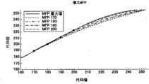
在一些实施例中,MFP/FTP可自动被确定且可被设置成使色阶曲线的斜率在上限处为0。以此方式确定的一系列色阶函数在图12中示出。在这些实施例中,MFP/FTP的最大值可被确定为使色阶函数在255处的斜率为0。这是不会引起削波的最大MFP/FTP值。In some embodiments, MFP/FTP can be determined automatically and can be set such that the slope of the tone scale curve is zero at the upper limit. A series of tone scale functions determined in this way are shown in FIG. 12 . In these embodiments, the maximum value of MFP/FTP may be determined such that the slope of the tone scale function at 255 is zero. This is the maximum MFP/FTP value that will not cause clipping.
在如参照图11所述的本发明的一些实施例中,处理HP信号118与在处理低通信号时使用的MFP/FTP的选择无关。该HP信号118用恒定增益116处理,该恒定增益116在功率/光源照明降低时或图像码值以其它方式增大以改进亮度时将保持对比度。按照全背光功率(BL)或降低背光功率的HP信号增益116的公式作为高通增益方程在以下立即给出。HP对比度增大对噪声是稳健的,因为增益通常较小(例如针对80%的功率降低和γ2.2,增益为1.1)。In some embodiments of the invention as described with reference to FIG. 11, processing the
方程12

在一些实施例中,一旦已通过LUT处理或以其它方式将色阶映射112应用于LP信号,并且已将恒定增益116应用于HP信号,就可对这些频率分量求和(115)并且在一些情形中对其削波。当添加至LP值的增大HP值超过255时,削波可能是必要的。这通常仅对具有高对比度的明亮信号相关。在一些实施例中,通过色阶LUT结构确保LP信号不超出上限。HP信号可引起总和中的削波,但HP信号的负值永不会削波,从而甚至在削波的确发生时保持某个对比度。In some embodiments, once the
图像相关源光实施例Image Dependent Source Light Embodiment
在本发明的一些实施例中,显示光源照度级可根据所显示图像、先前显示图像、要在所显示图像之后显示的图像或其它组合的特征来调节。在这些实施例中,显示光源照度级可根据图像特征变化。在一些实施例中,这些图像特征可包括图像辉度级、图像色度级、图像直方图特征以及其它图像特征。In some embodiments of the invention, the display light source illumination level may be adjusted based on characteristics of the displayed image, previously displayed images, images to be displayed after the displayed image, or other combinations. In these embodiments, the display light source illumination level may vary according to image characteristics. In some embodiments, these image characteristics may include image luminance levels, image chrominance levels, image histogram characteristics, and other image characteristics.
一旦已查明图像特性,光源(背光)照度级就可变化以增强一个或多个图像属性。在一些实施例中,光源级可减小或增大以增强较暗或较亮的图像区域中的对比度。光源照度级也可增大或减小以增大图像的动态范围。在一些实施例中,光源级可被调节以最优化每个图像帧的功耗。Once the image characteristics have been ascertained, the light source (backlight) illumination level can be varied to enhance one or more image attributes. In some embodiments, light source levels may be decreased or increased to enhance contrast in darker or brighter image areas. Light source illumination levels can also be increased or decreased to increase the dynamic range of the image. In some embodiments, light source levels may be adjusted to optimize power consumption per image frame.
当不管出自何因光源级已被修改时,图像像素的代码值可使用色阶调节来调节以进一步改进该图像。如果光源级已被减小以保存功率,则像素值可被增大以重获所丢失的亮度。如果光源级已被更改以增强特定辉度范围内的对比度,则像素值可被调节以补偿另一范围内的降低对比度或进一步增强该特定范围。When the light source level has been modified for whatever reason, the code values of the image pixels can be adjusted using tone scale adjustments to further improve the image. If the light source level has been reduced to conserve power, the pixel value can be increased to regain the lost brightness. If light source levels have been altered to enhance contrast within a particular range of luminance, pixel values may be adjusted to compensate for reduced contrast within another range or to further enhance that particular range.
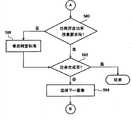
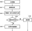
在本发明的一些实施例中,如图13所示,图像色阶调节可取决于图像内容。在这些实施例中,可分析(130)图像以确定图像特性。图像特性可包括辉度通道特性,诸如作为图像平均辉度的平均图片级(APL)、最大辉度值、最小辉度值、诸如直方图均值的辉度直方图数据、最频繁的直方图值等、以及其它辉度特性。图像特性还可包括色彩特性,诸如单个色彩通道(例如RGB信号中的R,G & B)的特性。每个色彩通道可被独立分析以确定色彩通道专属图像特性。在一些实施例中,对每个色彩通道可使用一单独的直方图。在其它实施例中,结合有关于图像数据的空间分布的团块直方图(blobhistogram)数据可被用作图像特性。图像特性还可包括视频帧之间的时间改变。In some embodiments of the present invention, as shown in FIG. 13 , image level adjustment may depend on image content. In these embodiments, the image may be analyzed (130) to determine image characteristics. Image properties may include luminance channel properties such as average picture level (APL) which is the average luminance of the image, maximum luminance value, minimum luminance value, luminance histogram data such as histogram mean, most frequent histogram value etc., and other luminance characteristics. Image characteristics may also include color characteristics, such as characteristics of individual color channels (eg R, G & B in an RGB signal). Each color channel can be analyzed independently to determine color channel-specific image characteristics. In some embodiments, a separate histogram may be used for each color channel. In other embodiments, blobhistogram data associated with the spatial distribution of the image data may be used as the image characteristic. Image characteristics may also include temporal changes between video frames.
一旦已分析了(130)图像且已确定了特性,就可基于该图像特性的值计算色阶映射或从一组预先计算的映射中选择一色阶映射(132)。然后该映射可应用于(134)图像以补偿背光调节或以其它方式增强该图像。Once the image has been analyzed (130) and properties have been determined, a tone scale map may be calculated or selected from a set of pre-calculated maps (132) based on the value of the image property. This mapping can then be applied (134) to the image to compensate for backlight adjustments or otherwise enhance the image.
本发明的一些实施例可关于图14进行描述。在这些实施例中,图像分析器142接收图像140并确定可用来选择色阶映射的图像特性。这些特性然后被发送至色阶映射选择器143,其基于这些图像特性确定适当的映射。此映射选择然后可发送至图像处理器145,以供将该映射应用于图像140。图像处理器145将接收映射选择和原始图像数据,并用所选色阶映射144处理原始图像,由此产生经调节图像,该经调节图像被发送至显示器146以供向用户显示。在这些实施例中,储存一个或多个色阶映射144以供基于图像特性作出选择。这些色阶映射144可预先被计算并储存为表格或某其它数据格式。这些色阶映射144可包括简单的γ转换表、利用以上相关于图5、7、10和11所述的方法创建的增强映射、或其它映射。Some embodiments of the invention may be described with respect to FIG. 14 . In these embodiments,
本发明的一些实施例可关于图15进行描述。在这些实施例中,图像分析器152接收图像150并确定可用来计算色阶映射的图像特性。这些特性然后被发送至色阶映射计算器153,其可基于这些图像特性计算适当的映射。所计算的映射然后可发送至图像处理器155,以供将该映射应用于图像150。图像处理器155将接收所计算映射154和原始图像数据,并用该色阶映射154处理该原始图像,由此产生经调节图像,该经调节图像被发送至显示器156以供向用户显示。在这些实施例中,基于图像特性基本上实时地计算色阶映射154。所计算的色阶映射154可包括简单的γ转换表、利用以上相关于图5、7、10和11所述的方法创建的增强映射、或另一映射。Some embodiments of the invention may be described with respect to FIG. 15 . In these embodiments,
本发明的其它实施例可关于图16进行描述。在这些实施例中,光源照度级可取决于图像内容,而色阶映射也取决于图像内容。然而,源光计算通道和色阶映射通道之间不一定有任何通信。Other embodiments of the invention may be described with respect to FIG. 16 . In these embodiments, the light source illumination level may depend on the image content, and the tone scale mapping may also depend on the image content. However, there doesn't necessarily have to be any communication between the source light calculation pass and the level map pass.
在这些实施例中,分析图像(160)以确定源光或色阶映射计算所需的图像特性。此信息然后被用来计算适于该图像的源光照度级161。该源光数据然后被发送(162)至显示器以供在显示图像时变更源光(例如背光)。图像特性数据还被发送至色阶映射通道,在其中基于图像特性信息选择或计算(163)色阶映射。该映射然后被应用于(164)图像以产生发送至显示器(165)的增强图像。为图像计算的源光信号与增强图像数据同步,以使源光信号与增强图像数据的显示相一致。In these embodiments, the image (160) is analyzed to determine image characteristics required for source light or tone scale mapping calculations. This information is then used to calculate a source
如图17所示的这些实施例的一部分采用所储存的色阶映射,这些色阶映射可包括简单的γ转换表、利用以上相关于图5、7、10和11所述的方法创建的增强映射、或另一映射。在这些实施例中,图像170被发送至图像分析器172以确定与色阶映射和源光计算相关的图像特性。这些特性然后被发送至源光计算器177以供确定适当的源光照度级。一些特性还可被发送至色阶映射选择器173,以供在确定适当的色阶映射174时使用。原始图像170和映射选择数据然后被发送至图像处理器175,该图像处理器175取回所选映射174并将该映射174应用于图像170以创建增强图像。此增强图像然后被发送至显示器176,该显示器176还接收来自源光计算器177的源光级信号,并使用该信号来在显示增强图像时调制源光179。Some of these embodiments, as shown in FIG. 17, employ stored tone scale maps, which may include simple gamma conversion tables, enhanced mapping, or another mapping. In these embodiments,
图18所示的这些实施例中的一部分可在传输过程中计算色阶映射。这些映射可包括简单的γ转换表、利用以上相关于图5、7、10和11所述的方法创建的增强映射、或另一映射。在这些实施例中,图像180被发送至图像分析器182以确定与色阶映射和源光计算相关的图像特性。这些特性然后被发送至源光计算器187以供确定适当的源光照度级。一些特性还可被发送至色阶映射计算器183,以供在计算适当的色阶映射184时使用。原始图像180和所计算的映射184然后被发送至图像处理器185,该图像处理器185将映射184应用于图像180以创建增强图像。此增强图像然后被发送至显示器186,该显示器186还接收来自源光计算器187的源光级信号,并使用该信号来在显示增强图像时调制源光189。Some of these embodiments shown in Figure 18 may compute the tone scale map on the fly. These maps may include simple gamma conversion tables, enhanced maps created using the methods described above in relation to Figures 5, 7, 10 and 11, or another map. In these embodiments,
本发明的一些实施例可参照图19进行描述。在这些实施例中,分析图像(190)以确定相关于源光和色阶映射计算与选择的图像特性。这些特性然后用来计算(192)源光照度级。该源光照度级然后被用来计算或选择色阶调节映射(194)。此映射然后应用于(196)该图像以创建增强图像。该增强图像和源光级数据然后被发送(198)至显示器。Some embodiments of the invention may be described with reference to FIG. 19 . In these embodiments, the image (190) is analyzed to determine image properties related to source light and tone scale map calculations and selections. These characteristics are then used to calculate (192) the source light illumination level. This source light illumination level is then used to calculate or select a tone scale adjustment map (194). This mapping is then applied (196) to the image to create an enhanced image. The enhanced image and source light level data are then sent (198) to a display.
用于相关于图19所述方法的装置可参照图20进行描述。在这些实施例中,在确定图像特性的图像分析器202处接收图像200。图像分析器202然后可将图像特性数据发送至源光计算器203以供确定源光级。源光级数据然后可被发送至色阶映射选择器或计算器204,该色阶映射选择器或计算器204可基于光源级计算或选择色阶映射。所选映射207或所计算映射然后可连同原始图像一起被发送至图像处理器205,以供将该映射应用于原始图像。该过程将产生增强图像,该增强图像与源光级信号一起被发送至显示器206,该源光级信号被用来在显示图像时调制显示源光。Apparatus for use in the method described in relation to FIG. 19 may be described with reference to FIG. 20 . In these embodiments,
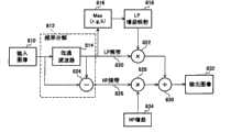
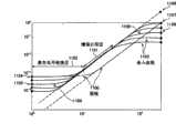
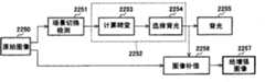
在本发明的一些实施例中,源光控制单元负责选择源光减弱,这将维持图像质量。关于在自适应阶段保持图像质量的能力的知识用来引导对源光级的选择。在一些实施例中,重要的是意识到在图像较亮或图像包含高度饱和色彩即代码值为255的蓝色时需要高源光级。仅使用辉度来确定背光级可在具有低辉度但大代码值即饱和蓝色或红色的图像的情况下引起伪像。在一些实施例中,可检查每个色彩面,并基于所有色彩面的最大值作出决定。在一些实施例中,背光设置可基于经削波的单个特定百分比的像素。在图22所示的其它实施例中,背光调制算法可使用两个百分比:削波像素百分比236和畸变像素百分比235。选择具有这些不同值的背光设置向色阶计算器提供平滑滚降色阶函数而非强加硬削波的空间。给定输入图像,确定每个色彩面的代码值的直方图。给定两个百分比P削波236和P畸变235,检查每个色彩面221-223的直方图以确定对应于这些百分比224-226的代码值。这给出了C削波(色彩)228和C畸变(色彩)227。不同色彩面之中的最大经削波代码值234和最大经畸变代码值233可用来确定背光设置229。此设置确保对于每个色彩面,至多指定百分比的代码值将被削波或畸变。In some embodiments of the invention, the source light control unit is responsible for selecting the source light attenuation which will maintain the image quality. Knowledge about the ability to preserve image quality during the adaptation phase is used to guide the selection of source light levels. In some embodiments, it is important to realize that high source light levels are required when the image is bright or the image contains a highly saturated color, ie blue with a code value of 255. Using only luminance to determine the backlight level can cause artifacts in the case of images with low luminance but large code values, ie saturated blue or red. In some embodiments, each color plane may be examined and a decision made based on the maximum value of all color planes. In some embodiments, the backlight setting may be based on a single specific percentage of pixels that are clipped. In other embodiments shown in FIG. 22 , the backlight modulation algorithm may use two percentages: a clipped
方程13Equation 13

通过检查将被用于补偿的色阶(TS)函数并选择背光(BL)百分比以使该色阶函数将在代码值Cv削波234下在255处削波,BL百分比得以确定。该色阶函数在值Cv畸变(此斜率之值将对BL减弱作补偿)之下将是线性的,在255处对Cv削波之上的代码值将是恒定的,且具有连续导数。检查这些导数阐明如何选择较低斜率并因此阐明如何选择背光功率,以使对低于Cv畸变的代码值而言不会有图像畸变。The BL percentage is determined by examining the tone scale (TS) function to be used for compensation and choosing the backlight (BL) percentage such that the tone scale function will clip at 255 at
在如图21所示的TS导数的曲线中,值H是未知的。对于将Cv削波映射至255的TS,TS导数之下的面积必须是255。该限制允许如下地确定H之值。In the curve of the derivative of TS as shown in Fig. 21, the value H is unknown. For a TS that maps Cvclipping to 255, the area under the derivative of TS must be 255. This constraint allows the value of H to be determined as follows.
方程14


BL百分比根据代码值增大和显示γ以及对畸变点之下代码值的准确补偿的标准来确定。将在Cv削波处削波并允许从Cv畸变之下无畸变的平滑过渡的BL比由以下方程给出:The BL percentage is determined based on the criteria of code value increase and display gamma and accurate compensation for code values below the distortion point. The BL ratio that will clip at Cvclipping and allow a smooth transition from Cv belowdistortion without distortion is given by the following equation:
方程15

另外为了解决BL变化的问题,对BL比设置上限。In addition, in order to solve the problem of BL variation, an upper limit is set for the BL ratio.
方程16

时间低通滤波231可应用于以上导出的图像相关BL信号以补偿LCD与BL之间同步的缺失。示例性背光调制算法的示图在图22中示出,在其它实施例中可使用不同的百分比和值。Temporal low-
色阶映射可补偿所选背光设置,同时最小化图像畸变。如上所述,背光选择算法基于对应色阶映射运算的能力来设计。所选BL级允许色阶函数补偿背光级而对第一指定百分比以下的代码值无畸变,并对第二指定百分比以上的代码值削波。该两个指定百分比允许色阶函数在无畸变和削波范围之间平滑转换。Level mapping compensates for selected backlight settings while minimizing image distortion. As mentioned above, the backlight selection algorithm is designed based on the capability of the corresponding tone scale mapping operation. The selected BL level allows the level scale function to compensate the backlight level without distortion for code values below a first specified percentage, and to clip code values above a second specified percentage. The two specified percentages allow the Levels function to transition smoothly between the undistorted and clipping ranges.
环境光感测实施例Ambient Light Sensing Embodiment
本发明的一些实施例包括环境照度传感器,其可向图像处理模块和/或源光控制模块提供输入。在这些实施例中,包括色阶调节、增益映射和其它修改的图像处理可与环境照度特性相关。这些实施例还可包括与环境照度特性相关的源光或背光调节。在一些实施例中,源光和图像处理可在单个处理单元中组合。在其它实施例中,这些功能可由单独的单元来执行。Some embodiments of the invention include an ambient illumination sensor that may provide input to the image processing module and/or the source light control module. In these embodiments, image processing including tone scale adjustments, gain mapping, and other modifications may be related to ambient illuminance characteristics. These embodiments may also include source light or backlight adjustments related to ambient illuminance characteristics. In some embodiments, source light and image processing may be combined in a single processing unit. In other embodiments, these functions may be performed by separate units.
本发明的一些实施例可参照图23进行描述。在这些实施例中,环境照度传感器270可被用作图像处理方法的输入。在一些示例性实施例中,输入图像260可基于来自环境照度传感器270和源光268级的输入来被处理。为了节电或出于其它原因,可调制或调节诸如用于照亮LCD显示面板266的背光的源光268。在这些实施例中,图像处理器262可接收来自环境照度传感器270和源光268的输入。基于这些输入,图像处理器262可修改输入图像以应对环境条件和源光268照度级。输入图像260可根据以上针对其它实施例所述方法的任一种方法或通过其它方法来修改。在一示例性实施例中,色阶映射可应用于该图像以相对于降低的源光照度和环境照度变化来增大图像像素值。经修改图像264然后可在诸如LCD面板的显示面板266上配准。在一些实施例中,当环境光低时源光照度级可降低,并且当色阶调节或其它像素值处理技术被用来补偿源光照度降低时,源光照度级可被进一步降低。在一些实施例中,当环境照度降低时源光照度级可被降低。在一些实施例中,当环境照度达到上阈值和/或下阈值时,源光照度级可被提高。Some embodiments of the invention may be described with reference to FIG. 23 . In these embodiments, the
本发明的一些实施例可参照图24进行描述。在这些实施例中,在图像处理单元282处接收输入图像280。输入图像280的处理还可取决于来自环境照度传感器290的输入。此处理还可取决于来自源光处理单元294的输出。在一些实施例中,源光处理单元294可接收来自环境照度传感器290的输入。一些实施例还可接收来自设备模式指示器292的输入,诸如可指示设备功耗模式、设备电池状况或某些其它设备状况的功率模式指示器。源光处理单元294可使用环境光状况和/或设备状况来确定源光照度级,该源光照度级被用来控制将照亮诸如LCD显示器286的显示器的源光288。源光处理单元还可将源光照度级和/或其它信息传递给图像处理单元282。Some embodiments of the invention may be described with reference to FIG. 24 . In these embodiments, an
图像处理单元282可使用来自源光处理单元294的源光信息来确定用于处理输入图像280的处理参数。该图像处理单元282可应用色阶调节、增益映射或其它过程来调节图像像素值。在一些示例性实施例中,此过程将改进图像亮度和对比度,并且部分或全部地补偿光源照度减弱。图像处理单元282处理的结果是经调节图像284,该经调节图像284可被发送至可被源光288照亮的显示器286。
本发明的其他实施例可参照图25进行描述。在这些实施例中,在图像处理单元302处接收输入图像300。输入图像300的处理可取决于来自环境照度传感器310的输入。此处理还可取决于来自源光处理单元314的输出。在一些实施例中,源光处理单元314可接收来自环境照度传感器310的输入。一些实施例还可接收来自设备模式指示器312的输入,诸如可指示设备功耗模式、设备电池状况或某其它设备状况的功率模式指示器。源光处理单元314可使用环境光状况和/或设备状况来确定源光照度级,该源光照度级被用来控制将照亮诸如LCD显示器306的显示器的源光308。该源光处理单元还可将源光照度级和/或其它信息传递给图像处理单元302。Other embodiments of the present invention may be described with reference to FIG. 25 . In these embodiments, an
图像处理单元302可使用来自源光处理单元314的源光信息来确定用于处理输入图像300的处理参数。图像处理单元302还可使用来自环境照度传感器310的环境照度信息来确定用于处理输入图像300的处理参数。该图像处理单元302可应用色阶调节、增益映射或其它过程来调节图像像素值。在一些示例性实施例中,此过程将改进图像亮度和对比度,并且部分或全部地补偿光源照度减弱。图像处理单元302处理的结果是经调节图像304,该经调节图像304可被发送至可被源光308照亮的显示器306。
本发明的另一些实施例可参照图26进行描述。在这些实施例中,在图像处理单元322处接收输入图像320。输入图像320的处理可取决于来自环境照度传感器330的输入。此处理还可取决于来自源光处理单元334的输出。在一些实施例中,源光处理单元334可接收来自环境照度传感器330的输入。在其它实施例中,环境信息可从图像处理单元322接收。源光处理单元334可使用环境光状况和/或设备状况来确定中间源光照度级。此中间源光照度级可被发送至源光后处理器332,该源光后处理器332可采取量化器、定时处理器或可修改中间源光照度级以适应特定设备的需求的某其它模块的形式。在一些实施例中,源光后处理器332可针对光源328类型和/或诸如视频应用程序的图像处理应用程序所强加的定时限制来修改光源控制信号。然后该经后处理的信号可被用来控制将照亮诸如LCD显示器326的显示器的源光328。源光处理单元还可将经后处理的源光照度级和/或其它信息传递给图像处理单元322。Other embodiments of the present invention may be described with reference to FIG. 26 . In these embodiments, an
图像处理单元322可使用来自源光后处理器332的源光信息来确定用于处理输入图像320的处理参数。图像处理单元322还可使用来自环境照度传感器330的环境照度信息来确定用于处理输入图像320的处理参数。该图像处理单元322可应用色阶调节、增益映射或其它过程来调节图像像素值。在一些示例性实施例中,此过程将改进图像亮度和对比度,并且部分或全部地补偿光源照度减弱。图像处理单元322处理的结果是经调节图像344,该经调节图像344可被发送至可被源光328照亮的显示器326。
本发明的一些实施例可包括单独的图像分析模块342、362和图像处理模块343、363。尽管这些单元可被集成在单个组件中或单个芯片上,但它们被例示和描述为单独的模块以便于更佳地描述其交互。Some embodiments of the invention may include separate
本发明的一些实施例可参照图27进行描述。在这些实施例中,在图像分析模块342处接收输入图像340。该图像分析模块可分析图像以确定图像特性,该图像特性可被传递至图像处理模块343和/或源光处理模块354。输入图像340的处理可取决于来自环境照度传感器330的输入。在一些实施例中,源光处理模块354可接收来自环境照度传感器350的输入。源光处理单元354也可接收来自设备状况或模式传感器352的输入。源光处理单元354可使用环境光状况、图像特性和/或设备状况来确定源光照度级。此源光照度级可被发送至将照亮诸如LCD显示器346的显示器的源光348。源光处理模块354还可将经后处理的源光照度级和/或其它信息传递给图像处理模块343。Some embodiments of the invention may be described with reference to FIG. 27 . In these embodiments, an input image 340 is received at an image analysis module 342 . The image analysis module may analyze the image to determine image characteristics, which may be passed to the image processing module 343 and/or the source light processing module 354 . Processing of input image 340 may depend on input from
图像处理模块322可使用来自源光处理模块354的源光信息来确定用于处理输入图像340的处理参数。图像处理模块343还可使用通过源光处理模块354从环境照度传感器350传递的环境照度信息。此环境照度信息可用来确定用于处理输入图像340的处理参数。该图像处理模块343可应用色阶调节、增益映射或其它过程来调节图像像素值。在一些示例性实施例中,此过程将改进图像亮度和对比度,并且部分或全部地补偿光源照度减弱。图像处理模块343处理的结果是经调节图像344,该经调节图像344可被发送至可被源光348照亮的显示器346。
本发明的一些实施例可参照图28进行描述。在这些实施例中,在图像分析模块362处接收输入图像360。该图像分析模块可分析图像以确定图像特性,该图像特性可被传递至图像处理模块363和/或源光处理模块374。输入图像360的处理可取决于来自环境照度传感器370的输入。此处理还可取决于来自源光处理模块374的输出。在一些实施例中,环境信息可从图像处理模块363接收,该图像处理模块363可接收来自环境传感器370的环境信息。此环境信息可通过中途的图像处理模块363传递和/或处理,并传递给源光处理模块374。设备状况或模式也可从设备模块372被传递至源光处理模块374。Some embodiments of the invention may be described with reference to FIG. 28 . In these embodiments, an
源光处理单元374可使用环境光状况和/或设备状况来确定源光照度级。此源光照度级可被用来控制将照亮诸如LCD显示器366的显示器的源光368。源光处理单元374还可将源光照度级和/或其它信息传递给图像处理单元363。The source
图像处理模块363可使用来自源光处理模块374的源光信息来确定用于处理输入图像360的处理参数。图像处理模块363还可使用来自环境照度传感器370的环境照度信息来确定用于处理输入图像360的处理参数。该图像处理模块363可应用色阶调节、增益映射或其它过程来调节图像像素值。在一些示例性实施例中,此过程将改进图像亮度和对比度,并且部分或全部地补偿光源照度减弱。图像处理模块363处理的结果是经调节图像364,该经调节图像364可被发送至可被源光368照亮的显示器366。
畸变自适应功率管理实施例Embodiment of Distortion Adaptive Power Management
本发明的一些实施例包括用于解决包括移动设备和应用的显示设备的功率需要、显示特性、周围环境和电池限制的方法和系统。在一些实施例中,可使用三个族系的算法:显示功率管理算法、背光调制算法、以及亮度保持(BP)算法。尽管功率管理在电池供电的移动设备中具有较高优先级,但这些系统和方法也可应用于其它设备,这些设备可受益于出于节能、热管理和其它目的的功率管理。在这些实施例中,这些算法可相互作用,但它们的独特功能可包括:Some embodiments of the invention include methods and systems for addressing the power requirements, display characteristics, ambient environment, and battery constraints of display devices, including mobile devices and applications. In some embodiments, three families of algorithms may be used: display power management algorithms, backlight modulation algorithms, and brightness preservation (BP) algorithms. Although power management has a high priority in battery powered mobile devices, these systems and methods are also applicable to other devices that may benefit from power management for power saving, thermal management, and other purposes. In these embodiments, these algorithms may interact, but their unique capabilities may include:
功率管理-这些算法利用视频内容中的变化来管理一系列帧上的背光功率,从而最优化功耗。Power Management - These algorithms take advantage of changes in video content to manage backlight power over a series of frames to optimize power consumption.
背光调制-这些算法选择要用于单个帧的背光功率电平,并利用图像内的统计数据来最优化功耗。Backlight Modulation - These algorithms select the backlight power level to use for a single frame and use statistics within the image to optimize power consumption.
亮度保持-这些算法处理每个图像以补偿降低的背光功率并保持图像亮度,同时避免伪像。Brightness Preservation - These algorithms process each image to compensate for reduced backlight power and maintain image brightness while avoiding artifacts.
本发明的一些实施例可参照图29描述,图29包括指示这些实施例的组件的交互的简化框图。在一些实施例中,功率管理算法406可管理视频、图像序列或其它显示任务上的固定电池资源402,并可保证指定平均功耗同时保持质量和/或其它特性。背光调制算法410可接收来自功率管理算法406的指令,并以功率管理算法406所定义的限制为依据选择功率电平来有效地表示每个图像。亮度保持算法414可使用所选背光级415和可能的削波值413来处理图像,从而补偿减弱的背光。Some embodiments of the invention may be described with reference to Figure 29, which includes a simplified block diagram indicating the interaction of components of these embodiments. In some embodiments, the
显示功率管理display power management
在一些实施例中,显示功率管理算法406可管理视频、图像序列或其它显示任务上的功率使用分布。在一些实施例中,显示功率管理算法406可分派电池的固定能量来提供得到保证的工作寿命、同时保持图像质量。在一些实施例中,功率管理算法的一个目标是提供得到保证的对电池寿命的较低限制,以确保移动设备的可用性。In some embodiments, display
恒定功率管理Constant Power Management
符合任意目标的一种形式的功率控制是要选择将符合期望寿命的固定功率。示出基于恒定功率管理的系统的系统框图在图30中示出。要点在于功率管理算法436仅基于电池充满度432和期望寿命434来选择恒定背光功率。针对此背光级444的补偿442对每个图像446执行。One form of power control that meets any goal is to choose a fixed power that will match the expected lifetime. A system block diagram illustrating a system based on constant power management is shown in FIG. 30 . The point is that the
方程17恒定功率管理Equation 17 Constant Power Management

背光级444以及因此功耗与图像数据440无关。一些实施例可支持多个恒定功率模式,从而允许功率电平的选择基于功率模式作出。在一些实施例中,图像相关的背光调制不可用来简化系统实现。在其它实施例中,一些恒定功率电平可基于工作模式或用户偏好设置和选择。一些实施例可在单个降低功率电平即最大功率的75%的情况下使用此概念。
简单自适应功率管理Simple Adaptive Power Management
本发明的一些实施例可参照图31进行描述。这些实施例包括自适应功率管理算法456。因背光调制460引起的功率降低455被反馈回功率管理算法456,从而使图像质量得以改进、同时仍然提供期望系统寿命。Some embodiments of the invention may be described with reference to FIG. 31 . These embodiments include an adaptive
在一些实施例中,通过如方程18中随时间更新静态最大功率计算,图像相关背光调制情况下的节能可被包括在功率管理算法中。自适应功率管理可包括计算剩余电池充满度(mA-Hr)与剩余期望寿命(Hr)之比以向背光调制算法460给出功率上限(mA)。一般而言,背光调制460可选择此最大值之下的实际功率,从而进一步节能。在一些实施例中,因背光调制导致的节能可用通过剩余电池电荷或运行中平均选择功率的变化值的反馈的形式来反映,并因此影响后续的功率管理决定。In some embodiments, power savings in the case of image-dependent backlight modulation can be included in the power management algorithm by updating the static maximum power calculation over time as in
方程18自适应功率管理

在一些实施例中,如果电池状态信息不可用或不准确,则通过计算显示器所使用的能量即平均所选功率乘以工作时间、并且从初始电池电荷减去此能量,可估计剩余电池电荷。In some embodiments, if battery status information is not available or accurate, the remaining battery charge can be estimated by calculating the energy used by the display, the average selected power times the operating time, and subtracting this energy from the initial battery charge.
方程19估计剩余电池电荷Equation 19 estimates remaining battery charge
显示器所使用能量(t)=平均所选功率·tEnergy used by the display (t) = average selected power·t
剩余电荷(t)=初始电荷-显示器所使用能量(t)Residual charge (t) = initial charge - energy used by the display (t)
后一技术具有不与电池交互即可完成的优点。The latter technique has the advantage that it can be done without interacting with the battery.
功率-畸变管理Power-Distortion Management
发明人已观察到,在畸变与功率之间关系的研究中,许多图像在相同功率下展现极为不同的畸变。由于高功率使用产生的黑电平的上升,那些诸如曝光不足照片的具有低对比度的暗淡图像实际上在低功率下能显示得更好。功率控制算法可能以图像畸变来交换电池容量,而不是直接功率设置。在本发明的一些实施例中,如图29所示,功率管理技术可包括诸如最大畸变值的畸变参数403、以及给予背光控制算法410的最大功率401。在这些实施例中,功率管理算法406可使用来自背光调制算法410的当前图像的功率/畸变特性405形式的反馈。在一些实施例中,最大图像畸变可基于目标功率和当前帧的功率-畸变特性而被修改。在这些实施例中,除关于实际所选功率的反馈之外,功率管理算法可选择和提供畸变目标403,且可接收关于相应图像畸变405的反馈以及关于电池充满度402的反馈。在一些实施例中,可在功率控制算法中使用附加输入,诸如:环境电平408、用户偏好、以及工作模式(即视频/图形)。The inventors have observed that in studies of the relationship between distortion and power, many images exhibit very different distortions at the same power. Dark images with low contrast, such as underexposed photographs, actually appear better at low power due to the rise in black levels produced by high power use. Power control algorithms may trade image distortion for battery capacity rather than direct power settings. In some embodiments of the invention, as shown in FIG. 29 , the power management technique may include distortion parameters 403 such as a maximum distortion value, and a
本发明的一些实施例可尝试在一视频序列上最佳地分派功率、同时保持显示质量。在一些实施例中,对于给定视频序列,可将两个标准用于在所用总功率与图像畸变之间选择折衷。可使用最大图像畸变和平均图像畸变。在一些实施例中,这些项可被最小化。在一些实施例中,最小化图像序列上的最大畸变可通过对该序列中的每个图像使用相同畸变来实现。在这些实施例中,功率管理算法406可选择此畸变403,从而使背光调制算法410能选择符合此畸变目标403的背光级。在一些实施例中,当对每个图像选择的功率使得功率畸变曲线的斜率相等时,可实现最小化平均畸变。在此情形中,功率管理算法406可依赖于背光调制算法410选择功率畸变曲线的斜率,从而选择适当的背光级。Some embodiments of the invention may attempt to optimally allocate power over a video sequence while maintaining display quality. In some embodiments, for a given video sequence, two criteria may be used to select a tradeoff between total power used and image distortion. Maximum image distortion and average image distortion are available. In some embodiments, these terms can be minimized. In some embodiments, minimizing the maximum distortion over a sequence of images may be achieved by using the same distortion for each image in the sequence. In these embodiments, the
图32A和32B可用来例示在功率管理过程中考虑畸变时的节能。图32A是图像序列的连续帧的源光功率电平的曲线图。图32A示出维持多个帧之间的恒定畸变480所需的源光功率电平与恒定畸变曲线的平均功率482。图32B是图像序列的相同连续帧的图像畸变的曲线图。图32B示出因维持恒定功率设置产生的恒定功率畸变484、在整个序列中因维持恒定畸变产生的恒定畸变电平488、以及维持恒定功率时的平均恒定功率畸变486。恒定功率电平已被选择为等于恒定畸变结果的平均功率。由此,两种方法使用相同的平均功率。通过检查畸变发现,恒定功率484给出图像畸变中的显著变化。还注意到,尽管两者使用相同平均功率,但恒定功率控制的平均畸变486是恒定畸变算法的畸变488的10倍以上。Figures 32A and 32B may be used to illustrate power savings when distortion is considered in the power management process. Figure 32A is a graph of source light power levels for successive frames of an image sequence. Figure 32A shows the source light power level required to maintain constant distortion 480 between multiple frames versus the average power 482 of the constant distortion curve. Figure 32B is a graph of image distortion for the same consecutive frames of a sequence of images. Figure 32B shows the
实际上,对于一些应用而言,因为原始与降低功率图像之间的畸变必须在功率畸变函数的每一点上计算以评估功率-畸变折衷,所以可以证明最优化来使得一视频序列上的最大或平均畸变最小化过于复杂。每次畸变评估可要求计算背光减弱和相应的补偿性图像增亮,并将其与原始图像作比较。因此,一些实施例可包括用于计算或估计畸变特性的更简单方法。In fact, for some applications, since the distortion between the original and reduced-power images must be computed at each point of the power distortion function to evaluate the power-distortion trade-off, it can be proven that the optimization is such that the maximum or Average distortion minimization is too complicated. Each distortion evaluation may require calculation of backlight reduction and corresponding compensatory image brightening and comparison with the original image. Accordingly, some embodiments may include simpler methods for calculating or estimating distortion characteristics.
在一些实施例中,可使用一些近似。首先,观察到诸如均方差(MSE)的逐点畸变度量可根据图像代码值的直方图而非图像本身计算,如在方程20中所表达的。在此情形中,直方图是相对于在320x240分辨率下具有7680个样本的图像仅具有256个值的一维信号。这可通过按需对直方图进行二次采样来进一步缩减。In some embodiments, some approximations may be used. First, observe that a point-wise distortion metric such as mean square error (MSE) can be computed from a histogram of image code values rather than the image itself, as expressed in
在一些实施例中,通过假设用在补偿阶段中削波而非应用实际补偿算法图像得以简单缩放,可作出近似。在一些实施例中,在畸变度量中包括黑电平升高项也可能是有价值的。在一些实施例中,使用此项可能意味着针对全黑帧的最小畸变在零背光时发生。In some embodiments, an approximation can be made by assuming that the image is simply scaled with clipping in the compensation stage rather than applying the actual compensation algorithm. In some embodiments, it may also be valuable to include a black level boost term in the distortion metric. In some embodiments, using this may mean that the least distortion for a completely black frame occurs at zero backlight.
方程20简化畸变计算

在一些实施例中,为了计算给定功率电平下的畸变,对于每个代码值,可确定削波情况下的线性增大所引起的畸变。该畸变然后可按代码值的频率加权并求和以给出指定功率电平下的平均图像畸变。在这些实施例中,用于亮度补偿的简单线性增大不会给出供图像显示的可接受质量,但用作供计算背光变化所引起的图像畸变的估计结果的简单源。In some embodiments, to calculate the distortion at a given power level, for each code value, the distortion caused by a linear increase in the case of clipping may be determined. This distortion can then be weighted by the frequency of the code values and summed to give an average image distortion at a given power level. In these embodiments, a simple linear increase for brightness compensation does not give acceptable quality for image display, but serves as a simple source for calculating an estimate of image distortion caused by backlight changes.
在如图33所示的一些实施例中,为了控制功耗和图像畸变两者,功率管理算法500不仅可跟踪电池充满度506和剩余寿命508,而且也可控制图像畸变510。在一些实施例中,功耗上限512和畸变目标511可被提供给背光调制算法502。该背光调制算法502然后可选择符合功率限制和畸变目标两者的背光级512。In some embodiments as shown in FIG. 33 , the
背光调制算法(BMA)Backlight Modulation Algorithm (BMA)
背光调制算法502负责选择用于每个图像的背光级。此选择可基于要显示的图像和来自功率管理算法500的信号。通过尊重功率管理算法500所提供的对增大功率的限制512,可在期望寿命期间管理电池506。在一些实施例中,背光调制算法502可依赖于当前图像的统计数据来选择较低功率。这可以是对具体图像的节能之源。
一旦选择了适当的背光级415,背光416即被设置成所选电平,且此电平415被给予亮度保持算法414以确定必要补偿。对于一些图像和序列,允许少量的图像畸变可大大地降低所需背光功率。因此,一些实施例包括允许受控的图像畸变量的算法。Once the
图34是示出针对若干容限的畸变作为帧数的函数的样本DVD剪辑上节能的量的曲线图。具有零畸变的像素的百分比从100%变到97%再变到95%,且该视频剪辑上的平均功率被确定。平均功率的范围为从95%到60%。由此允许5%的像素畸变给出了附加35%的节能。这表明通过允许少量的图像畸变使显著节能成为可能。如果亮度保持算法能在引入少量畸变的同时保持主观质量,则可获得显著的节能。34 is a graph showing the amount of power savings on a sample DVD clip as a function of frame number for several tolerances of distortion. The percentage of pixels with zero distortion was varied from 100% to 97% to 95%, and the average power over the video clip was determined. The average power ranges from 95% to 60%. Allowing 5% pixel distortion thus gives an additional 35% power saving. This shows that significant power savings are possible by allowing a small amount of image distortion. Significant power savings can be obtained if the brightness preserving algorithm can maintain subjective quality while introducing a small amount of distortion.
本发明的一些实施例可参照图30进行描述。这些实施例还可包括来自环境光传感器438的信息,并且可针对移动应用降低复杂性。这些实施例包括由功率管理算法436提供的静态直方图百分比限制和动态最大功率限制。一些实施例可包括恒定功率目标,而其它实施例可包括更为复杂的算法。在一些实施例中,可通过计算各个色彩分量的直方图来分析图像。该直方图中出现指定百分比的代码值可针对每个色彩平面来计算。在一些实施例中,目标背光级可被选择成使代码值中的线性增大将仅仅引起从直方图中选出的代码值的削波。实际背光级可被选择为此目标电平和功率管理算法436所提供的背光级限值中的最小值。这些实施例可提供得到保证的功率控制,并且在可达到功率控制限制的情形中可允许有限量的图像畸变。Some embodiments of the invention may be described with reference to FIG. 30 . These embodiments may also include information from ambient
方程21基于直方图百分比的功率选择

P所选=min(P目标,P最大值)Pselected = min(Ptarget , Pmax )
基于图像畸变的实施例Embodiment based on image distortion
本发明的一些实施例可包括由功率管理算法提供的畸变限制和最大功率限制。图32B和34示出给定背光功率电平下的畸变的量根据图像内容来显著地改变。每个图像的功率-畸变行为的属性可在背光选择过程中利用。在一些实施例中,可通过计算各个色彩分量的直方图来分析当前图像。通过使用方程20的第二表达式计算一功率值范围上的畸变,可计算限定畸变(例如MSE)的功率畸变曲线。背光调制算法可选择具有指定畸变限值处或之下的畸变的最小功率作为目标电平。该背光级然后可被选择为此目标电平和功率管理算法所提供的背光级限值中的最小值。此外,所选电平下的图像畸变可被提供给功率管理算法以引导畸变反馈。功率畸变曲线和图像直方图的采样频率可被降低以控制复杂性。Some embodiments of the invention may include distortion limiting and maximum power limiting provided by power management algorithms. Figures 32B and 34 show that the amount of distortion at a given backlight power level varies significantly depending on the image content. The properties of the power-distortion behavior of each image can be exploited in the backlight selection process. In some embodiments, the current image may be analyzed by computing a histogram of each color component. By calculating the distortion over a range of power values using the second expression of
亮度保持(BP)Brightness Hold (BP)
在一些实施例中,BP算法基于所选背光级来增亮图像以补偿减弱照度。BP算法可控制引入到显示中的畸变,并且BP算法保持质量的能力规定背光调制算法可尝试节约多少功率。一些实施例可通过缩放图像并且削波超过255的值来补偿背光减弱。在这些实施例中,背光调制算法必须对降低功率持保守态度,否则烦扰的削波伪像将被引入,由此限制可能的节能。一些实施例被设计成以固定的功率降低保持要求最高的帧上的质量。这些实施例的一部分补偿单个背光级(即75%)。其它实施例可被通用化以供背光调制之用。In some embodiments, the BP algorithm brightens the image based on the selected backlight level to compensate for reduced illumination. The BP algorithm can control the distortion introduced into the display, and the ability of the BP algorithm to preserve quality dictates how much power the backlight modulation algorithm can try to save. Some embodiments may compensate for backlight reduction by scaling the image and clipping values above 255. In these embodiments, the backlight modulation algorithm must be conservative with reduced power, otherwise annoying clipping artifacts will be introduced, thereby limiting possible power savings. Some embodiments are designed to maintain quality on the most demanding frames with a fixed power reduction. Some of these embodiments compensate for a single backlight level (
亮度保持(BP)算法的一些实施例可利用对作为背光和图像数据的函数的从显示器输出的辉度的描述。利用该模型,BP可确定对图像的修改以补偿背光的减弱。就透射反射型显示器而言,BP模型可被修改以包括显示器反射方面的描述。从显示器输出的辉度成为背光、图像数据和环境的函数。在一些实施例中,BP算法可确定对图像的修改以补偿给定周围环境中背光的减弱。Some embodiments of the Brightness Preserve (BP) algorithm may utilize a description of the luminance output from the display as a function of the backlight and image data. Using this model, BP can determine modifications to the image to compensate for the reduction in backlight. For transflective displays, the BP model can be modified to include a description of the reflective aspects of the display. The luminance output from the display becomes a function of the backlight, image data and environment. In some embodiments, the BP algorithm may determine modifications to the image to compensate for the reduction in backlight in a given surrounding environment.
环境影响environmental impact
由于实现约束,一些实施例可包括用于确定BP参数的复杂性有限的算法。例如,开发完全在LCD模块上运行的算法限制了该算法可用的处理和存储器。在该示例中,对不同背光/环境组合产生替换γ曲线可用于一些BP实施例。在一些实施例中,可能需要对γ曲线的数量和分辨度作出限制。Due to implementation constraints, some embodiments may include limited complexity algorithms for determining BP parameters. For example, developing an algorithm that runs entirely on the LCD module limits the processing and memory available to the algorithm. In this example, generating alternate gamma curves for different backlight/environment combinations may be used in some BP embodiments. In some embodiments, it may be desirable to limit the number and resolution of gamma curves.
功率/畸变曲线Power/Distortion Curve
本发明的一些实施例可获取、估算、计算或以其它方式确定包括但不限于视频序列帧的图像的功率/畸变特性。图35是示出4个示例性图像的功率/畸变特性的曲线图。在图35中,图像C的曲线520对整个源光功率带保持负斜率。图像A、B和D的曲线522、524和526以负斜率下降直至达到最小值,然后以正斜率上升。对于图像A、B和D,增大源光功率实际上将在曲线的具有正斜率528的特定范围上增加畸变。这可能是由诸如但不限于LCD渗漏、或使所显示图像在观看者看来与代码值始终不同的其它显示不规则的显示特性引起的。Some embodiments of the invention may acquire, estimate, calculate or otherwise determine power/distortion characteristics of images including, but not limited to, frames of a video sequence. FIG. 35 is a graph showing power/distortion characteristics of four exemplary images. In FIG. 35,
本发明的一些实施例可使用这些特性来针对具体图像或图像类型确定适当的源光功率电平。可在畸变参数计算中考虑显示特性(例如LCD渗漏),这些显示特性用来针对图像确定适当的源光功率电平。Some embodiments of the invention may use these characteristics to determine the appropriate source light power level for a particular image or image type. Display characteristics (such as LCD bleeding) can be considered in the calculation of the distortion parameters, and these display characteristics are used to determine the appropriate source light power level for the image.
示例性方法exemplary method
本发明的一些实施例可关于图36进行描述。在这些实施例中,建立功率预算(530)。这可使用简单功率管理、自适应功率管理和上述其它方法或通过其它方法来执行。通常,建立功率预算可包括估算将允许诸如显示视频文件的显示任务完成的背光或源光功率电平,同时使用诸如电池电荷的一部分的固定功率资源。在一些实施例中,建立功率预算可包括确定将允许在固定功率量的情况下完成显示任务的平均功率电平。Some embodiments of the invention may be described with respect to FIG. 36 . In these embodiments, a power budget is established (530). This can be performed using simple power management, adaptive power management, and other methods described above or by other methods. In general, establishing a power budget may include estimating a backlight or source light power level that will allow a display task, such as displaying a video file, to be completed while using a fixed power resource such as a fraction of a battery charge. In some embodiments, establishing a power budget may include determining an average power level that will allow a display task to be completed with a fixed amount of power.
在这些实施例中,还可建立初始畸变标准(532)。通过估算将符合功率预算的降低的源光功率电平并测量该功率电平下的图像畸变,可确定此初始畸变标准。可在未经校正的图像上、已使用如上所述的亮度保持(BP)技术修改的图像上、或已用简化BP过程修改的图像上测量畸变。In these embodiments, initial distortion criteria may also be established (532). This initial distortion criterion can be determined by estimating a reduced source light power level that would meet the power budget and measuring image distortion at that power level. Distortion can be measured on uncorrected images, on images that have been modified using brightness preserving (BP) techniques as described above, or on images that have been modified with a simplified BP process.
一旦建立了该初始畸变标准,即可使用源光功率电平显示该显示任务的第一部分,这使得所显示的一个或多个图像的畸变特性遵照该畸变标准。在一些实施例中,可针对视频序列的每个帧选择源光功率电平以使每个帧符合畸变要求。在一些实施例中,光源值可被选择成保持恒定畸变或畸变范围、保持畸变低于指定水平、或以其它方式符合畸变标准。Once the initial distortion criterion is established, a first portion of the display task can be displayed using source light power levels that cause the distortion characteristics of the displayed image or images to comply with the distortion criterion. In some embodiments, the source light power level may be selected for each frame of the video sequence so that each frame meets the distortion requirements. In some embodiments, light source values may be selected to maintain a constant distortion or range of distortion, keep distortion below a specified level, or otherwise meet distortion criteria.
然后可估算(536)功耗以判定用来显示显示任务的第一部分的功率是否满足功率预算管理参数。可通过对每个图像、视频帧或其它显示任务元素使用固定量功率来分派功率。还可分派功率以使在一系列显示任务元素上所消耗的平均功率符合要求、而对每个显示任务元素消耗的功率可变化。也可使用其它功率分派方案。Power consumption may then be estimated (536) to determine whether the power used to display the first portion of the display task meets the power budget management parameters. Power may be allocated by using a fixed amount of power per image, video frame, or other display task element. Power can also be allocated so that the average power consumed over a series of display task elements is satisfactory, while the power consumed for each display task element can be varied. Other power allocation schemes may also be used.
当功率消耗估算536显示显示任务的第一部分的功耗不符合功率预算要求时,可修改畸变标准(538)。在可估算、假设、计算或以其它方式确定功率/畸变曲线的一些实施例中,畸变标准可被修改以按需允许或多或少的畸变,从而符合功率预算要求。尽管功率/畸变曲线是图像特定的,但可使用针对一序列的第一帧、针对一序列中的示例性图像、或针对代表显示任务的合成图像的功率/畸变曲线。When the
在一些实施例中,当多于预算量的功率被用于显示任务的第一部分且功率/畸变曲线的斜率为正时,可修改畸变标准以允许更少畸变。在一些实施例中,当多于预算量的功率被用于显示任务的第一部分且功率/畸变曲线的斜率为负时,可修改畸变标准以允许更多畸变。在一些实施例中,当少于预算量的功率被用于显示任务的第一部分且功率/畸变曲线的斜率为负或正时,可修改畸变标准以允许更少畸变。In some embodiments, when more than a budgeted amount of power is used to display the first portion of the task and the slope of the power/distortion curve is positive, the distortion criteria may be modified to allow for less distortion. In some embodiments, when more than a budgeted amount of power is used to display the first portion of the task and the slope of the power/distortion curve is negative, the distortion criteria may be modified to allow for more distortion. In some embodiments, when less than a budgeted amount of power is used to display the first portion of the task and the slope of the power/distortion curve is negative or positive, the distortion criteria may be modified to allow for less distortion.
本发明的一些实施例可参照图37进行描述。这些实施例通常包括具有有限功率的由电池供电的设备。在这些实施例中,估计或测量电池充满度或电荷(540)。还可估计或计算显示任务功率要求(542)。还可估计或以其它方式确定初始光源功率电平(544)。此初始光源功率电平可使用如以上针对恒定功率管理所述的电池充满度和显示任务功率要求或通过其它方法来确定。Some embodiments of the invention may be described with reference to FIG. 37 . These embodiments typically include battery powered devices with limited power. In these embodiments, battery fullness or charge is estimated or measured (540). Display task power requirements may also be estimated or calculated (542). An initial light source power level may also be estimated or otherwise determined (544). This initial light source power level may be determined using battery fullness and display task power requirements as described above for constant power management, or by other methods.
还可确定与初始光源功率电平相对应的畸变标准(546)。此标准可以是在初始光源功率电平下对示例性图像出现的畸变值。在一些实施例中,畸变值可基于未经校正图像、用实际或经估算BP算法修改的图像、或另一示例性图像。A distortion criterion corresponding to the initial light source power level may also be determined (546). This criterion may be the distortion value that occurs for an exemplary image at the initial light source power level. In some embodiments, the distortion values may be based on an uncorrected image, an image modified with an actual or estimated BP algorithm, or another exemplary image.
一旦确定了畸变标准(546),就估算显示任务的第一部分,并选择(548)将使显示任务的第一部分的畸变符合畸变标准的源光功率电平。然后使用所选源光功率电平显示(550)该显示任务的第一部分,并估算或测量(552)显示该部分期间所消耗的功率。当此功耗不符合功率要求时,可修改(554)该畸变标准以使功耗顺应功率要求。Once the distortion criteria are determined (546), a first portion of the display task is estimated and a source light power level is selected (548) that will cause the distortion of the first portion of the display task to meet the distortion criteria. The first portion of the display task is then displayed (550) using the selected source light power level and the power consumed during that portion of the display is estimated or measured (552). When the power consumption does not meet the power requirement, the distortion criterion can be modified (554) to make the power consumption conform to the power requirement.
本发明的一些实施例可参照图38A和38B进行描述。在这些实施例中,建立功率预算(560)并且还建立畸变标准(562)。这些通常都是参照诸如视频序列的具体显示任务建立的。然后选择图像(564),诸如视频序列的一个帧或一组帧。然后对所选图像估算降低源光功率电平(566),以使因降低源光功率电平产生的畸变符合畸变标准。此畸变计算可包括将估算或实际亮度保持(BP)方法应用于所选图像的图像值。Some embodiments of the invention may be described with reference to Figures 38A and 38B. In these embodiments, a power budget is established (560) and a distortion criterion is also established (562). These are usually established with reference to a specific display task such as a video sequence. An image is then selected (564), such as a frame or set of frames of a video sequence. The reduced source light power level is then estimated (566) for the selected image such that the distortion produced by the reduced source light power level meets the distortion criteria. This distortion calculation may include applying an estimated or actual brightness preserving (BP) method to the image values of the selected image.
然后可用BP方法修改所选图像(568)以补偿降低的光源功率电平。然后可测量经BP修改图像的实际畸变(570)并可关于此实际畸变是否符合畸变标准作出判定(572)。如果实际畸变不符合畸变标准,则可调节估算过程(574)并可重新估算降低的光源功率电平(566)。如果实际畸变的确符合畸变标准,则可显示所选图像(576)。然后可测量图像显示期间的功耗(578),并将其与功率预算约束580作比较。如果功耗符合功率预算约束,则可选择诸如视频帧的后续集合(584),除非显示任务完成(582),此时该过程将结束。如果选择了下一图像(584),则该过程将返回至点“B”,在此处将针对该图像估算降低的光源功率电平(566),且该过程将与对第一图像一样地继续。The selected image can then be modified (568) using the BP method to compensate for the reduced light source power level. The actual distortion of the BP modified image can then be measured (570) and a determination can be made as to whether this actual distortion meets the distortion criteria (572). If the actual distortion does not meet the distortion criteria, the estimation process may be adjusted (574) and the reduced light source power level may be re-estimated (566). If the actual distortion does meet the distortion criteria, the selected image may be displayed (576). Power consumption during image display can then be measured ( 578 ) and compared to
如果所选图像的功耗不符合功率预算约束(580),则可如以上针对其它实施例所述地修改畸变标准(586)并且将选择下一图像(584)。If the power consumption of the selected image does not meet the power budget constraints (580), the distortion criteria may be modified (586) as described above for other embodiments and the next image will be selected (584).
经改进的黑色电平实施例Improved Black Level Embodiment
本发明的一些实施例包括用于显示器黑色电平改进的方法和系统。一些实施例使用指定背光级并产生与色阶相匹配的辉度,这既保持了亮度又改进了黑色电平。其它实施例包括在其设计中包括黑色电平改进的背光调制算法。一些实施例可被实现为上述实施例的扩展或修改。Some embodiments of the invention include methods and systems for display black level improvement. Some embodiments use specified backlight levels and produce luminances that match the color scale, which maintains brightness while improving black levels. Other embodiments include backlight modulation algorithms that include black level improvement in their design. Some embodiments may be implemented as extensions or modifications of the above-described embodiments.
经改进的辉度匹配(目标匹配理想显示)Improved Luminance Matching (Target Match Ideal Display)
以上呈现的辉度匹配公式即方程7被用来确定代码值的线性缩放,这对背光减弱作出补偿。这在功率降低至75%的试验中被证明是有效的。在具有图像相关背光调制的一些实施例中,对于暗色帧可显著减弱背光,例如低于10%。对于这些实施例,在方程7中导出的代码值的线性缩放可能并不恰当,因为它可过度地增大暗色值。尽管采用这些方法的实施例可倍增功率降低显示器上的全功率输出,但这可能不用来最优化输出。因为全功率显示具有上升的黑色电平,所以对暗色场景再现此输出不能实现在较低背光功率设置的情况下可能的降低黑色电平的益处。在这些实施例中,可修改匹配标准且可导出对方程7中给出的结果的替换。在一些实施例中,理想显示的输出得到匹配。该理想显示可包括零黑色电平以及与全功率显示相同的最大输出,白色电平=W。此示例性理想显示对代码值cv的响应在方程22中可用最大输出W、显示γ和最大代码值的项来表达。The luminance matching formula presented above, Equation 7, is used to determine the linear scaling of the code values, which compensates for backlight dimming. This has been shown to be effective in trials where the power has been reduced to 75%. In some embodiments with image-dependent backlight modulation, the backlight may be reduced significantly, eg, below 10%, for dark frames. For these embodiments, the linear scaling of code values derived in Equation 7 may not be appropriate because it can unduly increase the dark value. Although embodiments employing these methods can multiply power down to full power output on a display, this may not be used to optimize output. Since full power displays have raised black levels, reproducing this output for dark scenes does not achieve the reduced black level benefits possible with lower backlight power settings. In these embodiments, the matching criteria can be modified and alternatives to the results given in Equation 7 can be derived. In some embodiments, the output of the ideal display is matched. The ideal display would include zero black level and the same maximum output as a full power display, white level = W. This exemplary ideal display response to code value cv can be expressed in
方程22理想显示

在一些实施例中,示例性LCD可具有相同的最大输出W和γ,但具有非零黑色电平B。此示例性LCD可使用上述GOG模型针对全功率输出建模。输出随功率小于100%的相关背光功率缩放。增益和偏移模型参数可由全功率显示的最大输出W和黑色电平B确定,如方程23所示。In some embodiments, an exemplary LCD may have the same maximum output W and gamma, but have a non-zero black level B. This exemplary LCD can be modeled for full power output using the GOG model described above. Output scales with relative backlight power for powers less than 100%. The gain and offset model parameters can be determined from the maximum output W and black level B of the full power display, as shown in Equation 23.
方程23全功率GOG模型Equation 23 full power GOG model


通过将全功率结果缩放相关功率倍数,可确定具有相关背光功率P的功率降低显示器的输出。By scaling the full power result by the relevant power factor, the output of a reduced power display with the relevant backlight power P can be determined.
方程24实际LCD输出与功率和代码值的关系Equation 24 Actual LCD Output vs. Power and Code Values

在这些实施例中,可修改代码值以使理想和实际显示的输出在可能时相等。(如果理想输出不小于或大于在实际显示上给定功率情况下可能的输出)In these embodiments, the code values may be modified so that the ideal and actual displayed outputs are equal when possible. (if the ideal output is not less than or greater than the possible output at the given power on the actual display)
方程25用于匹配输出的标准Equation 25 is used to match the criteria for the output

一些计算根据x,P,W,B求解
方程26用于匹配输出的代码值关系Equation 26 is used to match the code value relationship of the output
这些实施例显示用于将实际显示器上的理想输出与非零黑色电平相匹配的代码值关系的一些属性。在此情形中,在上端

方程27削波点Equation 27 Clipping Point

这些结果与先前对其中显示假设具有零黑色电平即对比率为无穷的其它实施例的开发相一致。These results are consistent with previous developments on other embodiments in which the display was assumed to have a zero black level, ie, an infinite contrast ratio.
背光调制算法Backlight modulation algorithm
在这些实施例中,结合有黑色电平考虑的辉度匹配理论通过实现给定功率下显示和具有零黑色电平的基准显示之间的匹配来确定背光调制算法。这些实施例使用辉度匹配理论来确定在图像以功率P显示时相比于在理想显示器上显示而必须具有的畸变。背光调制算法可使用最大功率限制和最大畸变限制来选择产生低于指定最大畸变的畸变的最小功率。In these embodiments, luminance matching theory incorporating black level considerations determines the backlight modulation algorithm by achieving a match between a display at a given power and a reference display with a black level of zero. These embodiments use luminance matching theory to determine the distortion an image must have when displayed at power P compared to an ideal display. The backlight modulation algorithm may use the maximum power limit and maximum distortion limit to select the minimum power that produces distortion below the specified maximum distortion.
功率畸变power distortion
在一些实施例中,给定由全功率下黑色电平和最大亮度所指定的目标显示和要求显示的图像,可计算给定功率P下显示图像时的畸变。通过削波大于受限功率显示的亮度的值并削波小于理想基准的黑色电平的值,可在理想基准显示器上仿真显示的受限功率和非零黑色电平。图像的畸变可被定义为原始图像代码值和经削波代码值之间的MSE,然而也可在一些实施例中使用其它畸变度量。In some embodiments, given a target display specified by black level and maximum brightness at full power and an image desired to be displayed, the distortion when displaying an image at a given power P can be calculated. The limited power and non-zero black level of a display can be emulated on an ideal reference display by clipping values greater than the brightness of the limited power display and clipping values less than the black level of the ideal reference. The distortion of an image may be defined as the MSE between the original image code value and the clipped code value, although other distortion metrics may also be used in some embodiments.
削波情况下的图像由功率相关代码值定义,且方程27中引入的削波限值在方程28中给出。The image in the case of clipping is defined by the power-dependent code value, and the clipping limit introduced in Equation 27 is given in Equation 28.
方程28经削波图像Equation 28 clipped image

理想显示上的图像与像素域中以功率P显示的图像之间的畸变变成The distortion between the image on the ideal display and the image displayed at power P in the pixel domain becomes
观察到这可使用图像代码值的直方图来计算。Observe that this can be calculated using a histogram of image code values.
色阶函数的定义可用来推导此畸变度量的等效形式,如方程29所示。The definition of the tone scale function can be used to derive an equivalent form of this distortion metric, as shown in Equation 29.
方程29畸变度量Equation 29 Distortion Metric

此度量包括高代码值和低代码值处削波误差的加权和。功率/畸变曲线可使用方程29的表达式对图像构建。图39是示出各个示例性图像的功率/畸变曲线的曲线图。图39示出针对整体白色图像的功率/畸变曲线590、针对黄花的明亮特写的功率/畸变曲线592、针对一群人的暗色低对比度图像的功率/畸变曲线594、针对整体黑色图像的功率/畸变曲线596、以及针对冲浪者在浪尖上的明亮图像的功率/畸变曲线598。This metric includes a weighted sum of clipping errors at high and low code values. A power/distortion curve can be constructed for an image using the expression of Equation 29. FIG. 39 is a graph showing power/distortion curves for various exemplary images. Figure 39 shows power/
如从图39可以看出,不同图像可具有相当不同的/功率-畸变关系。在极值处,黑色帧596在零背光功率下具有最小畸变,其中畸变在功率增至10%时急剧上升。相反,白色帧590在零背光下具有最大畸变,其中畸变稳定下降直到在100%功率下快速降低为零。明亮冲浪图像598示出随功率增加的畸变的稳定下降。另两个图像592和594在中间功率电平下显示最小畸变。As can be seen from Figure 39, different images can have quite different /power-distortion relationships. At the extreme, the
本发明的一些实施例可包括如下运算的背光调制算法:Some embodiments of the invention may include a backlight modulation algorithm that operates as follows:
1.计算图像直方图1. Calculate the image histogram
2.计算图像的功率畸变函数2. Calculate the power distortion function of the image
3.计算具有低于畸变限值的畸变的最低功率3. Calculate the lowest power with distortion below the distortion limit
4.(可任选)基于所提供的功率上限和下限限制所选功率4. (Optional) Limit the selected power based on the provided power upper and lower limits
5.选择计算出的用于背光的功率5. Select the calculated power for the backlight
在关于图40和41所述的一些实施例中,BL调制算法所选择的背光值604可被提供给BP算法并用于色阶设计。示出了平均功率602和畸变606。还示出了在此试验中使用的对平均功率的上限600。因为所使用的平均功率显著低于此上限,所以背光调制算法使用比简单使用等于此平均限值的固定功率低的功率。In some embodiments described with respect to Figures 40 and 41, the backlight value 604 selected by the BL modulation algorithm may be provided to the BP algorithm and used for color scale design. Average power 602 and
平滑色阶函数的导出Export of Smooth Levels Function
在本发明的一些实施例中,平滑色阶函数包括两个设计方面。第一个方面设想色阶参数给定,并确定符合那些参数的平滑色阶函数。第二个方面包括用于选择设计参数的算法。In some embodiments of the invention, the smooth tonescale function includes two design aspects. The first aspect assumes that color scale parameters are given, and determines a smooth color scale function that conforms to those parameters. The second aspect includes algorithms for selecting design parameters.
设想参数的色阶设计Color scale design of envisaged parameters
方程26所定义的代码值关系在削波至有效范围[cvMin,cvMax]时具有斜率不连续性。在本发明的一些实施例中,暗端处的平滑滚降可与方程7中明端处相似地定义。这些实施例设想其间色阶符合方程26的最大保真度点(MFP)和最小保真度点(LFP)两者。在一些实施例中,色阶可被构建为连续并在MFP和LFP两处具有连续一阶导数。在一些实施例中,色阶可通过极值点(ImageMinCV,cvMin)和(ImageMaxCV,cvMax)。在一些实施例中,在高端和低端两处可从仿射增大修改色阶。此外,图像代码值的限制可用来确定极值点而不使用固定限值。有可能在此结构中使用固定限值,但在大功率降低的情况下会产生问题。在一些实施例中,这些条件唯一地定义了分段二次色阶,推导如下。The code value relationship defined by Equation 26 has a slope discontinuity when clipping to the effective range [cvMin, cvMax]. In some embodiments of the invention, the smooth roll-off at the dark end can be defined similarly to that at the bright end in Equation 7. These embodiments contemplate both a maximum fidelity point (MFP) and a minimum fidelity point (LFP) between which the color scale conforms to Equation 26 . In some embodiments, the color scale can be constructed to be continuous with continuous first derivatives at both the MFP and LFP. In some embodiments, the color scale may pass through extreme points (ImageMinCV, cvMin) and (ImageMaxCV, cvMax). In some embodiments, the tone scale may be modified from an affine increase at both the high end and the low end. In addition, limits on image code values can be used to determine extreme points without using fixed limits. It is possible to use fixed limits in this configuration, but this creates problems in the case of large power reductions. In some embodiments, these conditions uniquely define a piecewise quadratic tone scale, derived as follows.
条件:condition:
方程30色阶定义
方程31色阶斜率Equation 31 Color scale slope
LFP和MFP处的色阶与一阶导数的连续性的快速观察产生。A quick observation of the continuity of color scales and first derivatives at LFP and MFP results.
方程32色阶参数B,C,E,F的解Solution of
B=αB=α
C=α·LFP+βC=α·LFP+β
E=αE=α
F=α·MFP+βF=α·MFP+β
端点将常数A和D确定为:The endpoints determine the constants A and D as:
方程33色阶参数A和D的解Solution of
在一些实施例中,设想MFP/LFP和ImageMaxCV/ImageMinCV可用,这些关系式定义色阶的平滑扩展。这使得选择这些参数的需要悬而未决。其它实施例包括用于选择这些设计参数的方法和系统。In some embodiments, it is envisaged that MFP/LFP and ImageMaxCV/ImageMinCV are available, these relations define a smooth extension of the color scale. This leaves open the need to choose these parameters. Other embodiments include methods and systems for selecting these design parameters.
参数选择(MFP/LFP)Parameter selection (MFP/LFP)
以上所述的相关应用中的本发明的一些实施例仅解决ImageMaxCV等于255、cvMax用来替换这些实施例中所引入的ImageMaxCV的情况下的MFP。那些前述实施例由于基于全功率显示而非理想显示的匹配而在低端具有线性色阶。在一些实施例中,MFP被选择成使平滑色阶在上限即ImageMaxCV处具有零斜率。在数学上,MFP通过以下方程来定义:Some embodiments of the present invention in related applications described above only address MFP in the case of ImageMaxCV equal to 255, cvMax used to replace ImageMaxCV introduced in these embodiments. Those previous embodiments have a linear tone scale at the low end due to matching based on a full power display rather than an ideal display. In some embodiments, the MFP is chosen such that the smooth scale has a zero slope at the upper limit, ImageMaxCV. Mathematically, MFP is defined by the following equation:
方程34 MFP选择标准
TS′(ImageMaxCV)=0TS'(ImageMaxCV)=0
2·D·(ImageMaxCV-MFP)+E=02·D·(ImageMaxCV-MFP)+E=0
此标准的解使MFP相关于上削波点和最大代码值:The solution of this criterion relates the MFP to the upper clipping point and the maximum code value:
方程35预先MFP选择标准
MFP=2·x高-ImageMaxCVMFP = 2 xhigh - ImageMaxCV
对于诸如P=80%的适度功率降低,此预先MFP选择标准适用。对于大功率降低,这些实施例可基于前述实施例的结果改进。For modest power reductions such as P=80%, this pre-MFP selection criterion applies. For large power reductions, these embodiments can be modified based on the results of the previous embodiments.
在一些实施例中,选择适于大功率降低的MFP选择标准。直接在方程35中使用值ImageMaxCV会引起问题。在功率低的图像中,期望低的最大代码值。如果图像中的最大代码值ImageMaxCV已知为小,则方程35给出MFP的合理值,但在一些情形中ImageMaxCV为未知或较大,其可导致不合理即负的MFP值。在一些实施例中,如果最大代码值未知或过高,则可为ImageMaxCV选择替换值并应用于以上结果。In some embodiments, MFP selection criteria suitable for large power reduction are selected. Using the value ImageMaxCV directly in
在一些实施例中,k可被定义为定义MFP可具有的经削波值x高的最小部分的参数。然后,k可被用来判定通过方程35计算的MFP是否合理,即In some embodiments, k may be defined as a parameter that defines the smallest fraction of clipped valuesxhigh that an MFP may have. Then, k can be used to judge whether the MFP calculated by
方程36“合理”MFP标准
MFP≥k·x高MFP≥k xhigh
如果所计算的MFP不合理,则该MFP可被定义为最小合理值,并且可确定ImageMaxCV的必要值(方程37)。MFP和ImageMaxCV的值然后可用来通过如上所述地确定色阶。If the calculated MFP is unreasonable, the MFP can be defined as the minimum reasonable value and the necessary value of ImageMaxCV can be determined (Equation 37). The values of MFP and ImageMaxCV can then be used to determine the color scale as described above.
方程37校正ImageMaxCV
MFP=k·x高MFP=k·xhigh
ImageMaxCV=(2-k)·x高ImageMaxCV=(2-k)·xhigh
一些实施例的MFP选择步骤归纳如下:The MFP selection steps of some embodiments are summarized as follows:
1.利用ImageMaxCV(或在其不可用时利用CVMax)计算候选MFP1. Compute candidate MFPs using ImageMaxCV (or CVMax if it's not available)
2.利用方程36测试合理性2. Test
3.如果不合理,则基于削波代码值的分数k定义MFP3. If unreasonable, define the MFP based on the fraction k of the clipping code value
4.利用方程37计算新的ImageMaxCV4. Calculate the new
5.利用MFP、ImageMaxCV和功率计算平滑色阶函数5. Using MFP, ImageMaxCV and power to calculate smooth color scale function
可应用类似的技术来使用ImageMinCV和x低来选择暗端处的LFP。A similar technique can be applied to select the LFP at the dark end using ImageMinCV andxlow .
基于色阶设计算法和自动参数选择的示例性色阶设计如图42-45所示。图42和43示出其中已选择11%的背光功率电平的示例性色阶设计。示出与MFP 610与LFP 612之间的色阶设计的线性部分相对应的线616。色阶设计614在MFP 610之上和LFP 612之下偏离线616,但在LFP 612与MFP 610之间与线616一致。图43是图42的色阶设计的暗区的放大图像。LFP 612清晰可见,且可看到色阶设计的较低部分曲线620偏离线性延伸部分622。Exemplary color scale designs based on the color scale design algorithm and automatic parameter selection are shown in Figures 42-45. Figures 42 and 43 show an exemplary tone scale design in which a backlight power level of 11% has been selected.
图44和45示出背光级选择为89%的最大功率的示例性色阶设计。图44示出与色阶设计的线性部分相一致的线634。线634表示理想显示响应。色阶设计636在MFP 630以上和LFP 632以下偏离(636、638)理想线性显示表示634。图45示出LFP 640以下的色阶设计636的暗端的放大视图,其中色阶设计642偏离理想显示延伸部分644。Figures 44 and 45 show an exemplary tone scale design with the backlight level chosen to be 89% of maximum power. Figure 44 shows line 634 that coincides with the linear portion of the tone scale design. Line 634 represents the ideal display response. The color scale design 636 deviates from (636, 638) ideal linear display representation 634 above MFP 630 and below LFP 632. 45 shows an enlarged view of the dark end of the tone scale design 636 below the
在本发明的一些实施例中,畸变计算可通过改变理想和实际显示图像之间的误差计算来修改。在一些实施例中,可用畸变像素之和来替代MSE。在一些实施例中,高区和低区的削波误差可不同地加权。In some embodiments of the invention, the distortion calculation can be modified by changing the error calculation between the ideal and actual displayed image. In some embodiments, the sum of distorted pixels may be used instead of MSE. In some embodiments, clipping errors for high and low regions may be weighted differently.
本发明的一些实施例可包括环境光传感器。如果环境光传感器可用,则该传感器可用来修改畸变度量,包括环境照明和屏幕反射的效果。这可用来修改畸变度量并因此修改背光调制算法。环境信息可用来通过在黑端指示相关感知削波点来控制色阶设计。Some embodiments of the invention may include ambient light sensors. If an ambient light sensor is available, it can be used to modify distortion metrics, including the effects of ambient lighting and screen reflections. This can be used to modify the distortion metric and thus the backlight modulation algorithm. Ambient information can be used to control level design by indicating the point of relative perceived clipping at the black end.
色彩保持实施例Color Preservation Example
本发明的一些实施例包括用于保持色彩特性同时增强图像亮度的系统和方法。在一些实施例中,亮度保持包括将全功率色域体(gamut solid)映射成功率降低显示的较小色域体。在一些实施例中,不同方法用来进行色彩保持。一些实施例保持色彩的色度/饱和度,以替换辉度增大的减少。Some embodiments of the invention include systems and methods for preserving color characteristics while enhancing image brightness. In some embodiments, brightness preservation includes mapping a full power gamut solid to a smaller gamut solid for a reduced power display. In some embodiments, different methods are used for color preservation. Some embodiments preserve the hue/saturation of the color in lieu of a decrease in luminance increase.
上述一些非色彩保持实施例独立地处理各个色彩通道,从而用来给出关于每个色彩通道的辉度匹配。在那些非色彩保持实施例中,高度饱和或高亮色彩可变得饱和度降低和/或在色度仿效处理中改变。色彩保持实施例解决了这些色彩伪像,但在一些情形中会略微地降低辉度增大。Some of the non-color preserving embodiments described above process each color channel independently, thereby serving to give a luminance match on each color channel. In those non-color preserving embodiments, highly saturated or highlighted colors may become desaturated and/or altered in the chroma emulation process. The color preserving embodiment addresses these color artifacts, but slightly reduces luminance boost in some cases.
在重组低通和高通通道时,一些色彩保持实施例也可采用削波操作。单独地削波每个色彩通道可再次产生色彩变化。在采用色彩保持削波的实施例中,削波操作可用来保持色度/饱和度。在一些情形中,此色彩保持削波可将经削波值的辉度降至其它非色彩保持实施例的辉度之下。Some color preserving embodiments may also employ clipping when recombining the low-pass and high-pass channels. Clipping each color channel individually again produces color shifts. In embodiments employing color preserving clipping, a clipping operation may be used to preserve hue/saturation. In some cases, this color preserving clipping can drop the luminance of the clipped value below that of other non-color preserving embodiments.
本发明的一些实施例可参照图46进行描述。在这些实施例中,读取输入图像650并确定指定像素位置的对应于不同色彩通道的代码值(652)。在一些实施例中,输入图像可以是具有记录在图像文件中的单独色彩通道信息的格式。在一示例性实施例中,可就红绿蓝(RGB)色彩通道记录图像。在其它实施例中,可以青、品红、黄、黑(CMYK)格式、Lab(暗室)、YUV或另一格式记录图像文件。输入图像可以是包括单独辉度通道的诸如Lab的格式、或没有单独辉度通道的诸如RGB的格式。当图像文件没有单独的色彩通道数据可用时,该图像文件可被转换成具有色彩通道数据的格式。Some embodiments of the invention may be described with reference to FIG. 46 . In these embodiments, an input image is read 650 and code values corresponding to different color channels are determined for a given pixel location (652). In some embodiments, the input image may be in a format with individual color channel information recorded in the image file. In an exemplary embodiment, images may be recorded for the red-green-blue (RGB) color channels. In other embodiments, image files may be recorded in cyan, magenta, yellow, black (CMYK) format, Lab (darkroom), YUV, or another format. The input image may be in a format such as Lab including a separate luminance channel, or in a format such as RGB without a separate luminance channel. When an image file does not have separate color channel data available, the image file may be converted to a format with color channel data.
一旦确定了每个色彩通道的代码值(652),就确定色彩通道代码值中的最大代码值(654)。然后此最大代码值可用来确定代码值调节模型的参数(656)。该代码值调节模型可用许多方式产生。在一些实施例中,可使用色阶调节曲线、增益函数或其它调节模型。在一示例性实施例中,可使用响应于降低的背光功率设置增强图像亮度的色阶调节曲线。在一些实施例中,代码值调节模型可包括如上所述相关于其它实施例的色阶调节曲线。代码值调节曲线然后可应用于(658)色彩通道代码值的每一个。在这些实施例中,代码值调节曲线的应用将导致相同的增益值被应用于每个色彩通道。一旦执行调节,就对图像中的每个像素继续该处理(660)。Once the code values for each color channel are determined (652), a maximum of the color channel code values is determined (654). This maximum code value can then be used to determine the parameters of the code value adjustment model (656). The code value adjustment model can be generated in a number of ways. In some embodiments, tone scale adjustment curves, gain functions, or other adjustment models may be used. In an exemplary embodiment, a tone scale adjustment curve that enhances image brightness in response to reduced backlight power settings may be used. In some embodiments, the code value adjustment model may include tone scale adjustment curves as described above with respect to other embodiments. A code value adjustment curve may then be applied (658) to each of the color channel code values. In these embodiments, application of the code value adjustment curve will result in the same gain value being applied to each color channel. Once adjustments are performed, the process continues for each pixel in the image (660).
本发明的一些实施例可参照图47进行描述。在这些实施例中,读取输入图像(670)并选择第一像素位置(672)。对所选像素位置确定第一色彩通道的代码值(674),并对所选像素位置确定第二色彩通道的代码值(676)。然后分析这些代码值并基于代码值选择标准选择这些代码值之一(678)。在一些实施例中,可选择最大代码值。此所选代码值然后可被用作将产生模型的代码值调节模型发生器680的输入。然后该模型可被应用于(682)第一和第二色彩通道代码值,其中基本相等的增益被应用于每个通道。在一些实施例中,从调节模型获得的增益值可被应用于所有色彩通道。然后处理可继续至下一像素(684),直至处理了整个图像。Some embodiments of the invention may be described with reference to FIG. 47 . In these embodiments, an input image is read (670) and a first pixel location is selected (672). A code value for the first color channel is determined for the selected pixel location (674), and a code value for the second color channel is determined for the selected pixel location (676). The code values are then analyzed and one of the code values is selected based on code value selection criteria (678). In some embodiments, a maximum code value may be selected. This selected code value can then be used as an input to the code value
本发明的一些实施例可参照图48进行描述。在这些实施例中,输入图像690被输入至系统。该图像然后被滤波(692)以创建第一频率范围图像。在一些实施例中,这可以是低通图像或某其它频率范围图像。还可产生第二频率范围图像(694)。在一些实施例中,可通过从输入图像减去第一频率范围图像来创建第二频率范围图像。在一些实施例中,当第一频率范围图像是低通(LP)图像时,第二频率范围图像可以是高通(HP)图像。第一频率范围图像中第一色彩通道的代码值然后可针对像素位置确定(696),并且第一频率范围图像中第二色彩通道的代码值也可在该像素位置上确定(698)。然后通过比较代码值或其特性来选择(700)色彩通道代码值之一。在一些实施例中,可选择最大代码值。然后可使用所选代码值作为输入来产生或访问(702)调节模型。这可产生可应用于(704)第一色彩通道代码值和第二色彩通道代码值的增益乘法器。Some embodiments of the invention may be described with reference to FIG. 48 . In these embodiments, an
本发明的一些实施例可参照图49进行描述。在这些实施例中,输入图像710可被输入至可标识要调节像素的像素选择器712。第一色彩通道代码值读取器714可读取所选像素的第一色彩通道的代码值。第二色彩通道代码值读取器716也可读取所选像素位置上第二色彩通道的代码值。这些代码值可在分析模块718中分析,其中将基于代码值特性来选择代码值之一。在一些实施例中,可选择最大代码值。此所选代码值然后可被输入至模型生成器720或可确定增益值或模型的模型选择器。此增益值或模型然后可被应用于(722)两个色彩通道的代码值,而不管该代码值是否被分析模块718选择。在一些实施例中,可在应用该模型时访问(728)输入图像。然后控制可被传递(726)回像素选择器712以遍历图像中的其它像素。Some embodiments of the invention may be described with reference to FIG. 49 . In these embodiments, an
本发明的一些实施例可参照图50进行描述。在这些实施例中,输入图像710可被输入至滤波器730以获取第一频率范围图像732和第二频率范围图像734。该第一频率范围图像可被转换以允许访问单独的色彩通道代码值736。在一些实施例中,输入图像可允许在不经任何转换的情况下访问色彩通道代码值。可确定第一频率范围的第一色彩通道的代码值738并且可确定第一频率范围的第二色彩通道的代码值740。Some embodiments of the invention may be described with reference to FIG. 50 . In these embodiments, the
这些代码值可被输入至可确定代码值特性的代码值特性分析器742。然后代码值选择器744可基于代码值分析来选择代码值之一。此选择然后可被输入至调节模型选择器或发生器746,其将基于代码值选择产生或选择增益值或增益映射。该增益值或映射然后可应用于(748)所调节像素处的两个色彩通道的第一频率范围代码值。此过程可重复,直至已调节了整个第一频率范围图像(750)。增益映射也可应用于(753)第二频率范围图像734。在一些实施例中,恒定增益因数可被应用于第二频率范围图像中的所有像素。在一些实施例中,第二频率范围图像可以是输入图像710的高通版本。经调节的第一频率范围图像750和经调节的第二频率范围图像753可相加或以其它方式组合(754)以创建经调节的输出图像756。These code values may be input to a code value characteristic analyzer 742 which may determine a characteristic of the code value. The code value selector 744 may then select one of the code values based on the code value analysis. This selection can then be input to an adjustment model selector or generator 746 which will generate or select a gain value or gain map based on the code value selection. This gain value or mapping may then be applied (748) to the first frequency range code values of the two color channels at the adjusted pixel. This process can be repeated until the entire first frequency range image has been adjusted (750). Gain mapping may also be applied ( 753 ) to the second frequency range image 734 . In some embodiments, a constant gain factor may be applied to all pixels in the second frequency range image. In some embodiments, the second frequency range image may be a high-pass version of the
本发明的一些实施例可参照图51进行描述。在这些实施例中,输入图像710可被发送至滤波器760或其它某处理器,以供将该图像分成多个频率范围图像。在一些实施例中,滤波器760可包括低通(LP)滤波器和处理器,该处理器用于从输入图像减去用LP滤波器创建的LP图像以创建高通(HP)图像。滤波器模块760可输出两个或多个频率特定图像762、764,每个图像具有特定的频率范围。第一频率范围图像762可具有第一色彩通道766和第二色彩通道768的色彩通道数据。这些色彩通道的代码值可被发送至代码值特性估计器770和/或代码值选择器772。此过程将导致色彩通道代码值之一的选择。在一些实施例中,将从特定像素位置的色彩通道数据选择最大代码值。此所选代码值可被传递至将产生代码值调节模型的调节模型生成器774。在一些实施例中,此调节模型可包括增益映射或增益值。然后此调节模型可被应用于(776)所分析像素的每个色彩特定代码值。此过程可对图像中的每个像素重复,从而产生第一频率范围经调节图像778。Some embodiments of the invention may be described with reference to FIG. 51 . In these embodiments, the
可任选地第二频率范围图像764可用单独的增益函数765来调节以增大其代码值。在一些实施例中可不应用调节。在其它实施例中,恒定增益因数可被应用于第二频率范围图像中的所有代码值。此第二频率范围图像可与经调节的第一频率范围图像778组合以形成经调节的组合图像781。Optionally the second
在一些实施例中,调节模型对第一频率范围图像的应用和/或增益函数对第二频率范围图像的应用可使一些图像代码值超过显示设备或图像格式的范围。在这些情形中,代码值可能需要被“削波”至所需范围。在一些实施例中,可使用色彩保持削波过程782。在这些实施例中,落于指定范围外的代码值可用保持这些色彩值之间的关系的方式来削波。在一些实施例中,可针对所分析像素计算乘数,其不大于最大所需范围值除以最大色彩通道代码值。这将导致“增益”因数小于1且将“过大”代码值减至所需范围的最大值。此“增益”或削波值可被应用于所有色彩通道代码值以保持像素的色彩,同时将所有代码值减至小于或等于最大值或指定范围的值。应用此削波过程产生经调节的输出图像784,其具有在指定范围内的所有代码值并且维持代码值的色彩关系。In some embodiments, application of an adjustment model to images of a first frequency range and/or application of a gain function to images of a second frequency range may cause some image code values to exceed the range of the display device or image format. In these cases, the code values may need to be "clipped" to the desired range. In some embodiments, a color preserving
本发明的一些实施例可关于图52进行描述。在这些实施例中,色彩保持削波被用于保持色彩关系,同时将代码值限制于指定范围。在一些实施例中,经组合的调节图像792可对应于相关于图51所述的经组合的调节图像781。在其它实施例中,经组合的调节图像792可以是具有需要被削波至指定范围的代码值的任何其它图像。Some embodiments of the invention may be described with respect to FIG. 52 . In these embodiments, color preserving clipping is used to preserve color relationships while limiting code values to specified ranges. In some embodiments, combined
在这些实施例中,针对指定像素位置确定第一色彩通道代码值794并确定第二色彩通道代码值796。这些色彩通道代码值794和796在代码值特性估算器798中估算以确定选择性代码值特性并选择色彩通道代码值。在一些实施例中,该选择性特性将是最大值,而较高代码值将被选择为调节生成器800的输入。所选代码值可被用作输入以生成削波调节800。在一些实施例中,此调节将把最大代码值减小为指定范围内的值。然后可将此削波调节应用于所有色彩通道代码值。在一示例性实施例中,第一色彩通道和第二色彩通道的代码值将减小(802)相同倍数,由此保持两个代码值之比。此过程对图像中所有像素的应用将产生代码值落于指定范围内的输出图像804。In these embodiments, a first color
本发明的一些实施例可参照图53进行描述。在这些实施例中,通过基于最大色彩分量操纵应用于所有三个色彩分量的增益,在RGB域中实现方法。在这些实施例中,输入图像810通过频率分解812被处理。在一示例性实施例中,低通(LP)滤波器814被应用于该图像以创建LP图像820,该LP图像然后从输入图像810减去以创建高通(HP)图像826。在一些实施例中,空间5x5整流滤波器可用于该LP滤波器。在LP图像820中的每个像素上,选择(816)最大值或三个色彩通道(R、G和B)并输入至LP增益映射818,该LP增益映射818选择要应用于该特定像素的所有色彩通道值的适当增益函数。在一些实施例中,具有值[r,g,b]的像素上的增益可根据由max(r,g,b)索引的1维LUT确定。值x处的增益可从如上所述值x处的光度匹配色阶曲线的值除以x来推导。Some embodiments of the invention may be described with reference to FIG. 53 . In these embodiments, the method is implemented in the RGB domain by manipulating the gains applied to all three color components based on the largest color component. In these embodiments, the
增益函数834还可应用于HP图像826。在一些实施例中,增益函数834可以是恒定增益因数。此经修改的HP图像与经调节的LP图像组合(830)以形成输出图像832。在一些实施例中,输出图像832可包括在应用范围之外的代码值。在这些实施例中,削波过程可如上相关于图51和52所述地应用。
在如上所述的本发明的一些实施例中,LP图像的代码值调节模型可被设计成使得对于其最大色彩分量低于例如最大保真度点的参数的像素,增益补偿背光功率电平的降低。在色域边界,以经处理的低通信号在色域内保持的方式低通增益平滑滚降至1。In some embodiments of the invention as described above, the code value adjustment model of the LP image can be designed such that for pixels whose maximum color component is below a parameter such as the maximum fidelity point, the gain compensates for the change in the backlight power level reduce. At the gamut boundaries, the low-pass gain rolls off smoothly to 1 in such a way that the processed low-pass signal remains within the gamut.
在一些实施例中,处理HP信号可与处理低通信号的选择无关。在补偿降低背光功率的实施例中,HP信号可用恒定增益处理,这将在功率降低时保持对比度。用全背光功率和降低背光功率以及显示γ来表示的HP信号增益的公式在5中给出。在这些实施例中,HP对比度增大对噪声是稳健的,因为增益通常较小(例如针对80%的功率降低和γ2.2增益为1.1)。In some embodiments, processing the HP signal may be independent of the selection of processing the low-pass signal. In an embodiment that compensates for reduced backlight power, the HP signal can be processed with a constant gain, which will maintain contrast as the power is reduced. Equations for the HP signal gain in terms of full and reduced backlight power and display γ are given in 5. In these embodiments, the HP contrast boost is robust to noise because the gain is typically small (eg, 1.1 for 80% power reduction and γ2.2 gain).
在一些实施例中,将处理LP信号和HP信号的结果求和并削波。削波可应用于每个像素处的RGB样本的整个向量,从而相等地缩放三个分量以使最大分量缩放至255。当添加至LP值的增大HP值超过255时削波发生,并且削波通常仅对具有高对比度的明亮信号相关。通常,通过LUT结构确保LP信号不超出上限。HP信号可引起总和中的削波,但HP信号的负值永不会削波,从而甚至在削波的确发生时保持某对比度。In some embodiments, the results of processing the LP signal and the HP signal are summed and clipped. Clipping can be applied to the entire vector of RGB samples at each pixel, scaling the three components equally to scale the largest component to 255. Clipping occurs when increasing HP values added to the LP value exceed 255, and clipping is generally only relevant for bright signals with high contrast. Usually, the LUT structure is used to ensure that the LP signal does not exceed the upper limit. The HP signal can cause clipping in the sum, but negative values of the HP signal never clip, maintaining some contrast even when clipping does occur.
本发明诸实施例可尝试最优化图像的亮度,或者它们可尝试最优化色彩保持或匹配同时增大亮度。通常在最大化辉度或亮度时会有色移的折衷。在防止色移时,通常亮度会受损。本发明的一些实施例可通过形成应用于每个色彩分量的加权增益来尝试平衡色移与亮度之间的折衷,如方程38所示。Embodiments of the invention may attempt to optimize the brightness of an image, or they may attempt to optimize color preservation or matching while increasing brightness. Often there is a tradeoff of color shift when maximizing luminance or brightness. When preventing color shift, usually brightness is compromised. Some embodiments of the invention may attempt to balance the tradeoff between color shift and brightness by forming weighted gains applied to each color component, as shown in Equation 38.
方程38加权增益Equation 38 Weighted gain
加权增益(cvx,α)=α·增益(cvx)+(1-α)·增益(max(cvR,cvG,cvB)Weighted gain (cvx , α) = α · gain (cvx ) + (1-α) · gain (max (cvR , cvG , cvB )
此加权增益在α0处的最大辉度与α1处的最小色彩伪像之间变化。注意,当所有代码值低于MFP参数时,所有三个增益相等。This weighting gain varies between maximum luminance at α0 and minimum color artifacts at α1. Note that all three gains are equal when all code values are below the MFP parameter.
基于显示模型的畸变相关实施例Display Model Based Distortion Related Embodiments
术语“背光缩放”可指用于减弱LCD背光且同时修改发送至LCD的数据以补偿背光减弱的技术。此技术的主要方面是选择背光级。本发明诸实施例可利用背光调制来选择LCD中的背光照度级,以节能或改进动态对比度。用来解决此问题的方法可被分成图像相关技术和图像无关技术。这些图像相关技术可具有约束由后续背光补偿图像处理所强加的削波量的目标。The term "backlight scaling" may refer to techniques for dimming the LCD backlight while modifying the data sent to the LCD to compensate for the dimming of the backlight. The main aspect of this technique is the selection of the backlight level. Embodiments of the present invention may utilize backlight modulation to select the backlight illumination level in an LCD to save power or improve dynamic contrast. Methods to solve this problem can be classified into image-related techniques and image-independent techniques. These image correlation techniques may have the goal of constraining the amount of clipping imposed by subsequent backlight compensation image processing.
本发明的一些实施例可利用最优化来选择背光级。给定一图像,最优化例程可选择背光级,以使假设基准显示上显现的图像与实际显示上显现的图像之间的畸变最小。Some embodiments of the invention may utilize optimization to select the backlight level. Given an image, the optimization routine may select the backlight level to minimize distortion between the image appearing on the hypothetical reference display and the image appearing on the actual display.
以下项可用来描述本发明诸实施例的元素:The following items may be used to describe elements of various embodiments of the invention:
1.基准显示模型:基准显示模型可表示来自诸如LCD的显示器的期望输出。在一些实施例中,基准显示模型可建模具有零黑色电平的理想显示或具有不受限动态范围的显示。1. Reference Display Model: A reference display model may represent the expected output from a display such as an LCD. In some embodiments, a reference display model may model an ideal display with zero black level or a display with unlimited dynamic range.
2.实际显示模型:实际显示的输出的模型。在一些实施例中,实际显示输出可对不同背光级建模,并且实际显示可被建模为具有非零黑色电平。在一些实施例中,背光选择算法可通过此参数取决于显示对比率。2. Actual display model: the actual displayed output model. In some embodiments, the actual display output can be modeled for different backlight levels, and the actual display can be modeled as having a non-zero black level. In some embodiments, the backlight selection algorithm may depend on the display contrast ratio by this parameter.
3.亮度保持(BP):处理原始图像以补偿降低的背光级。实际显示上显现的图像是增亮图像上给定背光级上显示模型的输出。一些示例性情形为:3. Brightness Preservation (BP): Processes raw images to compensate for reduced backlight levels. The image that appears on the actual display is the output of the display model at a given backlight level on the brightened image. Some example situations are:
●无亮度保持:未经处理的图像数据被发送至LCD面板。在此情形中,背光选择算法仅改变背光,相应地不保持亮度。●No Brightness Hold: Unprocessed image data is sent to the LCD panel. In this case, the backlight selection algorithm only changes the backlight, correspondingly the brightness is not maintained.
●线性增大亮度补偿。使用简单仿射变换处理图像以补偿背光减弱。尽管此简单亮度保持算法在实际用于背光补偿时牺牲了图像质量,但这是选择背光值的有效工具。●Linear increase brightness compensation. Processes the image using a simple affine transformation to compensate for backlight reduction. Although this simple brightness preservation algorithm sacrifices image quality when actually used for backlight compensation, it is an effective tool for selecting backlight values.
●色阶映射:使用色阶映射来处理图像,该色阶映射可包括线性和非线性分段。分段可用来限制削波并增强对比度。• Scale Mapping: Images are processed using a Scale Map, which may include linear and non-linear segments. Segmentation can be used to limit clipping and enhance contrast.
4.畸变度量。显示模型和亮度保持算法可用来确定在实际显示上所显现的图像。然后可计算此输出和基准显示上的图像之间的畸变。在一些实施例中,畸变可仅基于图像代码值来计算。此畸变取决于对误差度量的选择,在一些实施例中可使用均方差。4. Distortion metrics. Display models and brightness preservation algorithms can be used to determine the image that will appear on the actual display. The distortion between this output and the image on the reference display can then be calculated. In some embodiments, distortion may be calculated based only on image code values. This distortion depends on the choice of error metric, in some embodiments mean square error may be used.
5.最优化标准。畸变可依照不同约束来最小化。例如,在一些实施例中,可使用以下标准:5. Optimization criteria. Distortion can be minimized according to different constraints. For example, in some embodiments, the following criteria may be used:
●最小化视频序列的每一帧上的畸变● Minimize distortion on each frame of the video sequence
●依据平均背光约束来最小化最大畸变● Minimize the maximum distortion according to the average backlight constraint
●依据平均背光约束来最小化平均畸变●Minimize the average distortion according to the average backlight constraint
显示模型display model
在本发明的一些实施例中,可将GoG模型用于基准显示模型和实际显示模型两者。此模型可被修改以基于背光级缩放。在一些实施例中,基准显示可被建模为具有零背光级和最大输出W的理想显示。实际显示可被建模为具有全背光下的相同最大输出W和全背光下的黑色电平B。对比率为W/B。当黑色电平为零时对比率为无穷。这些模型可使用CVMax来在数学上表达,以表示以下方程中的最大图像代码值。In some embodiments of the invention, the GoG model can be used for both the reference display model and the actual display model. This model can be modified to scale based on backlight level. In some embodiments, the reference display may be modeled as an ideal display with zero backlight level and maximum output W. The actual display can be modeled as having the same maximum output W at full backlight and black level B at full backlight. The contrast is W/B. The contrast is infinite when the black level is zero. These models can be expressed mathematically using CVMax to represent the maximum image code value in the following equation.
方程39基准(理想)显示输出的模型Equation 39 benchmark (ideal) model showing output

对于在全背光级即P=1下具有最大输出W和最小输出B的实际LCD,输出被建模为随相关背光级P缩放。对比率CR=W/B与背光级无关。For a practical LCD with maximum output W and minimum output B at full backlight level, ie P=1, the output is modeled as scaling with the associated backlight level P. The contrast ratio CR=W/B is independent of the backlight level.
方程40实际LCD的模型


B(P)=P·B W(P)=P·WB(P)=P·B W(P)=P·W
CR=W/BCR=W/B
亮度保持brightness hold
在此示例性实施例中,使用基于简单增大和削波的BP过程,其中升压被选择以在可能时补偿背光减弱。以下推导示出色阶修改,其提供给定背光下基准显示和实际显示之间的辉度匹配。实际显示的最大输出和黑色电平两者随背光缩放。注意,实际显示的输出被限制成低于经缩放的输出最大值且高于经缩放的黑色电平。这对应于将辉度匹配色阶输出削波成0和CVmax.In this exemplary embodiment, a simple boost-and-clip based BP process is used, where boost is chosen to compensate for backlight dimming when possible. The following derivation shows a color scale modification that provides a luminance match between a reference display and an actual display for a given backlight. Both the actual maximum output displayed and the black level scale with the backlight. Note that the actual displayed output is limited below the scaled output maximum and above the scaled black level. This corresponds to clipping the luma-matched levelscale output to 0 and CVmax .
方程41用于匹配输出的标准Equation 41 is used to match the criteria for the output
Y理想(cv)=Y实际(P,cv′)Yideal (cv) = Yactual (P, cv')
对cv’的削波限制表示对辉度匹配的范围的削波限制。The clipping limit on cv' means the clipping limit on the range of luminance matching.
方程42削波限制
方程43削波点


色阶提供最小值以上最大值以下代码值的输出的匹配,其中最小值和最大值取决于相关背光功率P和实际显示对比率CR=W/B。The color scale provides matching of the output of the code values above the minimum value and below the maximum value, where the minimum and maximum values depend on the relative backlight power P and the actual display contrast ratio CR=W/B.
畸变计算Distortion calculation
在本发明诸实施例中创建和使用的各个经修改图像可参照图54进行描述。在创建这些示例性修改图像的每一个时,原始图像I 840可被用作输入。在一些实施例中,原始输入图像840被处理(842)以产生理想输出Y理想844。理想图像处理器即基准显示842可假设理想显示具有零黑色电平。此输出Y理想844可表示在基准(理想)显示上看到的原始图像840。在一些实施例中,假设给定背光级,可计算通过将具有此背光级的图像呈现在实际LCD上所引起的畸变。Various modified images created and used in embodiments of the invention may be described with reference to FIG. 54 . In creating each of these exemplary modified images, an original image I 840 may be used as input. In some embodiments,
在一些实施例中,亮度保持846可用来从图像I 840产生图像I’850。图像I’850然后可连同所选背光级被发送至实际LCD处理器854。所得输出被标记为Y实际858。In some embodiments, brightness hold 846 may be used to generate image I′ 850 from
该基准显示模型可通过使用输入图像I*852来仿真实际显示的输出。The reference display model can simulate the actual displayed output by using the input image I* 852 .
实际LCD 854的输出是通过辉度匹配色阶函数846传递原始图像I 840以获取图像I’850的结果。这实际上不会根据背光级来再现基准输出。然而,实际显示输出可在基准显示842上仿真。图像I*852表示发送至基准显示842以仿真实际显示输出从而创建Y仿真860的图像数据。通过将图像I 840削波至由以上相关于方程43和在他处定义的削波点确定的范围而产生图像I*852。在一些实施例中,I*在数学上可描述为:The output of the
方程44经削波图像

在一些实施例中,畸变可被定义为具有图像I的基准显示的输出与具有背光级P和图像I’的实际显示的输出之间的差异。因为图像I*仿真基准显示器上实际显示的输出,所以基准和实际显示之间的畸变等于基准显示上图像I和I*之间的畸变。In some embodiments, distortion may be defined as the difference between the output of a reference display with image I and the output of an actual display with backlight level P and image I'. Because image I* emulates the output actually displayed on the reference display, the distortion between the reference and actual display is equal to the distortion between images I and I* on the reference display.
方程45
D(Y理想,Y实际)=D(Y理想,Y仿真)D (ideal Y,actual Y) = D (ideal Y,simulation Y)
因为两个图像都在基准显示上,所以可在仅图像数据之间测量畸变而不需要显示输出。Because both images are on the reference display, distortion can be measured between image-only data without display output.
方程46
D(Y理想,Y仿真)=D(I,I*)D (Yideal , Ysimulation ) = D (I, I*)
图像畸变测量Image distortion measurement
以上分析示出了图像I 840在基准显示上的呈现与在实际显示上的呈现之间的畸变等效于图像I 840和I*852在基准显示上的呈现之间的畸变。在一些实施例中,逐点畸变度量可用来定义图像之间的畸变。给定逐点畸变d,可通过对图像I和I*之间的差异求和来计算图像之间的畸变。因为图像I*仿真辉度匹配,所以误差由上限和下限处的削波组成。在一些实施例中,标准化的图像直方图h(x)可被用来定义图像畸变与背光功率之间的关系The above analysis shows that the distortion between the presentation of image I 840 on the reference display and the presentation on the actual display is equivalent to the distortion between the presentation of images I 840 and I* 852 on the reference display. In some embodiments, a point-wise distortion metric may be used to define distortion between images. Given a pointwise distortion d, the distortion between images can be computed by summing the differences between images I and I*. Since the image I* emulates luminance matching, the error consists of clipping at the upper and lower limits. In some embodiments, a normalized image histogram h(x) can be used to define the relationship between image distortion and backlight power
方程47Equation 47

背光与畸变关系曲线Backlight vs Distortion Curve
给定基准显示、实际显示、畸变定义和图像,畸变可在一背光级范围上计算。在组合时,此畸变数据可形成背光与畸变关系曲线。背光与畸变关系曲线可使用样本帧以及具有零黑色电平的理想实际模型、具有1000∶1对比率的实际LCD模型、以及均方差MSE误差度量来例示,该样本帧是从暗室中向外看的视图的昏暗图像。图55是示例性图像的图像代码值的直方图的图表。Given a reference display, an actual display, a distortion definition, and an image, distortion can be calculated over a range of backlight levels. When combined, this distortion data forms a backlight vs. distortion curve. The backlight vs. distortion curve can be illustrated using a sample frame looking out from a dark room along with an ideal real model with zero black level, a real LCD model with a 1000:1 contrast ratio, and the mean square error MSE error metric dim image of the view. 55 is a graph of a histogram of image code values for an exemplary image.
在一些实施例中,畸变曲线可通过利用直方图计算一背光值范围的畸变来计算。图56是与图55的直方图相对应的示例性畸变曲线的图表;对于此示例性图像,在低背光值处,亮度保持不能有效地补偿减弱的背光,从而导致畸变的急剧增加880。在高背光级处,受限的对比率使黑色电平相比于理想显示升高882。最小畸变范围存在,并且在一些实施例中,给出此最小畸变884的最低背光值可通过最小畸变算法来选择。In some embodiments, the distortion curve can be calculated by calculating the distortion for a range of backlight values using a histogram. FIG. 56 is a graph of exemplary distortion curves corresponding to the histogram of FIG. 55; for this exemplary image, at low backlight values, brightness maintenance cannot effectively compensate for the reduced backlight, resulting in a sharp increase 880 in distortion. At high backlight levels, the limited contrast ratio raises the black level by 882 compared to the ideal display. A minimum distortion range exists, and in some embodiments, the lowest backlight value that gives this minimum distortion 884 can be selected by a minimum distortion algorithm.
最优化算法optimization algorithm
在一些实施例中,诸如图56所示畸变曲线的畸变曲线可被用来选择背光值。在一些实施例中,可选择每个帧的最小畸变功率。在一些实施例中,当最小畸变值不唯一时,可选择给出此最小畸变的最低功率884。将此最优化标准应用于简短DVD剪辑的结果在图57中示出,其标绘出所选背光功率对视频帧数的关系。在此情形中,平均所选背光890大致为50%。In some embodiments, a distortion curve such as that shown in FIG. 56 may be used to select the backlight value. In some embodiments, a minimum distortion power per frame may be selected. In some embodiments, when the minimum distortion value is not unique, the lowest power 884 that gives this minimum distortion may be selected. The results of applying this optimization criterion to a short DVD clip are shown in Figure 57, which plots the selected backlight power versus the number of video frames. In this case, the average selected
图像相关性image correlation
为了例示本发明一些实施例的图像相关性质,具有变化内容的示例性测试图像被选择,并且对一背光值范围计算这些图像中的畸变。图39是针对这些示例性图像的背光与畸变关系曲线的曲线图。图39包括多个曲线图:图像A 596,全黑图像;图像B 590,全白图像;图像C 594,一群人的极暗照片;以及图像D 598,冲浪者在浪尖上的明亮图像。To illustrate the image-dependent nature of some embodiments of the invention, exemplary test images with varying content were selected, and the distortions in these images were calculated for a range of backlight values. FIG. 39 is a graph of backlight versus distortion for these exemplary images. Figure 39 includes several graphs:
注意该曲线的形状极大地取决于图像内容。这可在背光级平衡因亮度损失引起的畸变和因黑色电平升高引起的畸变时预期。黑色图像596在低背光时具有最小畸变。白色图像590在全背光时具有最小畸变。昏暗图像594在中等背光级下具有最小畸变,其将有限对比率作为升高黑色电平与亮度减弱之间的有效平衡。Note that the shape of this curve depends greatly on the image content. This can be expected when the backlight level balances distortion due to loss of brightness and distortion due to increase in black level.
对比率contrast ratio
显示对比率可进入实际显示的定义。图58示出针对实际显示的不同对比率的最小MSE畸变背光确定。注意在1∶1对比率限制900下,最小畸变背光取决于图像平均信号电平(ASL)。在无穷对比率(零黑色电平)的相反极值下,最小畸变背光取决于图像最大值902。The display contrast ratio goes into the definition of the actual display. Figure 58 shows the minimum MSE distortion backlight determination for different contrast ratios of the actual display. Note that at a 1:1 contrast ratio limit of 900, the minimum distortion backlight depends on the image average signal level (ASL). At the opposite extreme of infinite contrast ratio (zero black level), the minimum distortion backlight depends on the
在本发明的一些实施例中,基准显示模型可包括具有理想零黑色电平的显示模型。在一些实施例中,基准显示模型可包括由视觉亮度模型选择的基准显示,并且在一些实施例中,基准显示模型可包括环境光传感器。In some embodiments of the invention, the reference display model may include a display model with an ideal zero black level. In some embodiments, the reference display model may include a reference display selected by a visual brightness model, and in some embodiments, the reference display model may include an ambient light sensor.
在本发明的一些实施例中,实际显示模型可包括具有有限黑色电平的透射GoG模型。在一些实施例中,实际显示模型可包括用于透射反射型显示器的模型,其中输出被建模为取决于环境光和显示器的反射部分。In some embodiments of the invention, the actual display model may include a transmissive GoG model with a finite black level. In some embodiments, the actual display model may include a model for a transflective display, where the output is modeled as dependent on ambient light and the reflective portion of the display.
在本发明的一些实施例中,背光选择过程中的亮度保持(BP)可包括具有削波的线性增大。在其它实施例中,背光选择过程可包括用平滑滚降和/或双通道BP算法的色阶运算器。In some embodiments of the invention, brightness hold (BP) during backlight selection may include a linear increase with clipping. In other embodiments, the backlight selection process may include a color scale operator with smooth roll-off and/or a two-pass BP algorithm.
在本发明的一些实施例中,畸变度量可包括图像代码值中的均方差(MSE)作为逐点度量。在一些实施例中,畸变度量可包括含绝对差之和的逐点误差度量、多个削波像素和/或基于直方图的百分比度量。In some embodiments of the invention, the distortion metric may include mean square error (MSE) in image code values as a point-wise metric. In some embodiments, the distortion metric may include a point-wise error metric with sum of absolute differences, a number of clipped pixels, and/or a histogram-based percentage metric.
在本发明的一些实施例中,最优化标准可包括选择使每一帧中的畸变最小化的背光级。在一些实施例中,最优化标准可包括使最大畸变最小化或使平均畸变最小化的平均功率限制。In some embodiments of the invention, optimization criteria may include selecting a backlight level that minimizes distortion in each frame. In some embodiments, optimization criteria may include an average power limit that minimizes maximum distortion or minimizes average distortion.
LCD动态对比度实施例LCD Dynamic Contrast Ratio Example
液晶显示器(LCD)通常因有限对比率而受损。例如,显示器的黑色电平可因为背光泄漏或其它问题而被升高。这可导致黑色区域看起来是灰色而非黑色。通过降低背光级和相关联泄漏从而也降低黑色电平,背光调制可减轻此问题。然而,在不补偿的情况下使用时,该技术将具有降低显示亮度的非期望效果。图像补偿可用来恢复因背光调暗而损失的显示亮度。补偿通常已被约束为恢复全功率显示的亮度。Liquid crystal displays (LCDs) generally suffer from limited contrast ratios. For example, the black level of a display may be raised due to backlight leakage or other problems. This can cause black areas to appear gray instead of black. Backlight modulation alleviates this problem by reducing the backlight level and associated leakage, thereby also reducing the black level. However, when used without compensation, this technique will have the undesired effect of reducing display brightness. Image compensation can be used to restore display brightness lost due to backlight dimming. Compensation has generally been constrained to restore the brightness of a full power display.
如上所述的本发明的一些实施例包括集中于节能的背光调制。在那些实施例中,目标是以低背光级呈现全功率输出。这可通过同时调暗背光并增亮图像来实现。黑色电平或动态对比度的改进是那些实施例中的有利副作用。在这些实施例中,目标是实现图像质量改进。一些实施例可产生以下的图像质量改进:Some embodiments of the invention as described above include backlight modulation focused on power saving. In those embodiments, the goal is to present full power output at low backlight levels. This is accomplished by simultaneously dimming the backlight and brightening the image. An improvement in black level or dynamic contrast is a beneficial side effect in those embodiments. In these embodiments, the goal is to achieve image quality improvements. Some embodiments may result in the following image quality improvements:
1.由于背光减弱的低黑色电平,1. Low black level due to dimmed backlight,
2.通过减弱背光引起的泄漏减少而改进暗色的饱和度2. Improve the saturation of dark colors by reducing the leakage caused by weakening the backlight
3.在使用比背光减弱强的补偿时,亮度改进3. Brightness improvement when using stronger compensation than backlight reduction
4.动态对比度即一序列的明亮帧中的最大值除以暗帧中的最小值的改进4. Improvement of dynamic contrast, that is, the maximum value in a sequence of bright frames divided by the minimum value in dark frames
5.暗帧中的帧内对比度5. Intra-frame contrast in dark frames
本发明的一些实施例可经由两种基本技术实现这些益处的一种或多种:背光选择和图像补偿。一种挑战是避免视频中的闪烁伪像,因为背光和经补偿图像两者在亮度上都将有变化。本发明的一些实施例可使用目标色调曲线来降低闪烁的可能性。在一些实施例中,目标曲线可具有超过面板(具有固定背光)对比率的对比率。目标曲线可用于两个目的。首先,目标曲线可在选择背光时使用。其次,目标曲线可用来确定图像补偿。目标曲线影响以上提及的图像质量方面。目标曲线可从全背光亮度下的显示峰值延伸至最低背光亮度下的最小显示值。因此,目标曲线将延伸至用全背光亮度实现的典型显示值的范围之下。Some embodiments of the invention may achieve one or more of these benefits via two basic techniques: backlight selection and image compensation. One challenge is avoiding flickering artifacts in video, since both the backlight and the compensated image will have variations in brightness. Some embodiments of the invention may use a target tone curve to reduce the likelihood of flicker. In some embodiments, the target curve may have a contrast ratio that exceeds the contrast ratio of the panel (with a fixed backlight). The target curve serves two purposes. First, target curves are available when selecting a backlight. Second, the target curve can be used to determine image compensation. The target curve affects the image quality aspects mentioned above. The target curve extends from the peak display value at full backlight brightness to the minimum display value at minimum backlight brightness. Therefore, the target curve will extend below the range of typical display values achieved with full backlight brightness.
在一些实施例中,背光辉度或亮度级的选择可对应于与自然面板对比率相对应的目标曲线的区间的选择。此区间随背光变化而移动。在全背光下,目标曲线的暗区不能在面板上呈现。在低背光下,目标曲线的亮区不能在面板上呈现。在一些实施例中,为了确定背光,给出面板色调曲线、面板色调曲线、以及要显示的图像。背光级可被选择成使具有所选背光的面板的对比度范围最接近地匹配目标色调曲线下图像值的范围。In some embodiments, selection of backlight luminance or brightness level may correspond to selection of an interval of a target curve corresponding to a natural panel contrast ratio. This range moves with backlight changes. In full backlight, dark areas of the target curve cannot be rendered on the panel. Under low backlight, the bright areas of the target curve cannot be represented on the panel. In some embodiments, to determine the backlight, the panel tone curve, the panel tone curve, and the image to be displayed are given. The backlight level may be selected such that the contrast range of the panel with the selected backlight most closely matches the range of image values under the target tone curve.
在一些实施例中,图像可被修改或补偿以使显示输出尽可能多地落在目标曲线上。如果背光过高,则目标曲线的暗区不能实现。同样如果背光低,则目标曲线的亮区不能实现。在一些实施例中,可通过将固定目标用于补偿来最小化闪烁。在这些实施例中,背光亮度与图像补偿两者变化,但显示输出逼近固定的目标色调曲线。In some embodiments, the image may be modified or compensated so that the displayed output falls as much as possible on the target curve. If the backlight is too high, the dark areas of the target curve cannot be achieved. Also if the backlight is low, the bright regions of the target curve cannot be achieved. In some embodiments, flicker can be minimized by using a fixed target for compensation. In these embodiments, both backlight brightness and image compensation are varied, but the display output approaches a fixed target tone curve.
在一些实施例中,目标色调曲线可归纳以上列出的图像质量改进的一个或多个。背光选择与图像补偿两者可通过目标色调曲线来控制。可执行背光亮度选择以“最优地”呈现图像。在一些实施例中,上述的基于畸变的背光选择算法可用指定目标色调曲线和面板色调曲线来应用。In some embodiments, the target tone curve may incorporate one or more of the image quality improvements listed above. Both backlight selection and image compensation can be controlled through the target tone curve. Backlight brightness selection can be performed to "optimally" render the image. In some embodiments, the distortion-based backlight selection algorithm described above can be applied with a specified target tone curve and panel tone curve.
在一些示例性实施例中,增益-偏移-γ杂光(GOGF)模型可用于色调曲线,如方程49所示。在一些实施例中,2.2的值可用于γ且0可用于偏移,从而留下两个参数——增益和杂光。面板和目标色调曲线两者都可用这两个参数来指定。在一些实施例中,增益确定最大亮度,而对比率确定加性杂光项。In some exemplary embodiments, a gain-offset-gamma flare (GOGF) model may be used for the tone curve, as shown in Equation 49. In some embodiments, a value of 2.2 may be used for gamma and 0 may be used for offset, leaving two parameters - gain and flare. Both panel and target tone curves can be specified with these two parameters. In some embodiments, the gain determines the maximum brightness, while the contrast ratio determines the additive flare term.
方程48色调曲线模型Equation 48 Tone Curve Model
其中CR是显示的对比率,M是最大面板输出,c是图像代码值,T是色调曲线值,而γ是伽玛值。where CR is the contrast ratio of the display, M is the maximum panel output, c is the image code value, T is the tone curve value, and γ is the gamma value.
为实现动态对比度改进,目标色调曲线与面板色调曲线不同。在最简单应用中,目标的对比率CR大于面板的对比率。示例性面板色调曲线在方程49中示出,To achieve dynamic contrast improvement, the target tone curve differs from the panel tone curve. In the simplest application, the contrast ratio CR of the target is greater than that of the panel. An exemplary panel tone curve is shown in Equation 49,
方程49示例性面板色调曲线Equation 49 Exemplary Panel Tone Curve

其中CR是面板的对比率,M是最大面板输出,c是图像代码值,T是面板色调曲线值,而γ是伽玛值。where CR is the contrast ratio of the panel, M is the maximum panel output, c is the image code value, T is the panel tone curve value, and γ is the gamma value.
示例性面板色调曲线在方程50中示出,An exemplary panel tone curve is shown in
方程50示例性目标色调曲线

其中CR是目标的对比率,M是最大目标输出(例如全背光亮度下的最大面板输出),c是图像代码值,T是目标色调曲线值,而γ是伽玛值。where CR is the target contrast ratio, M is the maximum target output (e.g. maximum panel output at full backlight brightness), c is the image code value, T is the target tone curve value, and γ is the gamma value.
一些示例性色调曲线的方面可相关于图60进行描述。图59是水平轴上代码值和垂直轴上相对辉度的双对数标绘图。其中示出了三条色调曲线:面板色调曲线1000、目标色调曲线1001和幂定律曲线1002。面板色调曲线1000从面板黑色点1003延伸至最大面板值105。目标色调曲线从目标黑色点1004延伸至最大目标/面板值1005。目标黑色点1004因为受益于较低背光亮度而低于面板黑色点1003,但是,目标色调曲线的整个范围不能用于单个图像,因为对于任意给定帧背光可仅具有一个亮度级,因此当背光亮度被减弱以获得较低目标黑色点1004时不能实现最大目标/面板值1005。本发明诸实施例选择目标色调曲线最适于所显示图像和期望性能目标的范围。Aspects of some exemplary tone curves may be described with respect to FIG. 60 . Figure 59 is a log-log plot of code value on the horizontal axis and relative luminance on the vertical axis. Three tone curves are shown:
可产生多条目标色调曲线以实现不同优先级。例如,如果节能是主要目标,则针对目标曲线M和CR的值可被设置成等于面板色调曲线中的相应值。在该节能实施例中,目标色调曲线等于自然面板色调曲线。背光调制被用来节能,同时除该范围的顶端外,所显示图像实质上与全功率下显示上的图像相同,这在低背光设置下是不可获得的。Multiple target tone curves can be generated to achieve different priorities. For example, if energy saving is the main goal, the values for the target curves M and CR can be set equal to the corresponding values in the panel tone curve. In this energy saving embodiment, the target tone curve is equal to the natural panel tone curve. Backlight modulation is used to save power, while the displayed image is essentially the same as on the display at full power except for the top end of the range, which is not achievable at low backlight settings.
示例性节能色调曲线在图60中示出。在这些实施例中,面板和目标色调曲线相同1010。背光亮度被减弱,由此允许更低可能目标曲线1011的可能性,但是此可能性在这些实施例中不使用。相反,通过补偿图像代码值,图像被增亮以匹配面板色调曲线1010。当这不可能时,在由于为节能而减弱背光的面板限制1013下,补偿可被舍入1012以避免削波伪像。此舍入可根据以上相关于其它实施例描述的方法来实现。在一些实施例中,可允许削波或者可由于图像中的受限动态范围而不进行削波。在那些情形中,舍入1012可能不是必要的,并且目标色调曲线在范围顶端1014处可简单地跟随面板色调曲线。An exemplary energy saving tone curve is shown in FIG. 60 . In these embodiments, the panel and target tone curves are identical 1010. The backlight brightness is reduced, thereby allowing the possibility of a lower possible target curve 1011, but this possibility is not used in these embodiments. Instead, the image is brightened to match the
在另一示例性实施例中,当较低黑色电平是主要目标时,目标曲线的M的值可被设置成等于面板色调曲线中的相应值,但目标曲线的CR的值可被设置成等于面板色调曲线中相应值的4倍。在这些实施例中,目标色调曲线被选择成降低黑色电平。显示亮度相对于全功率显示不变。目标色调曲线具有与面板相同的最大值M,但具有更高的对比率。在以上示例中,对比率是自然面板对比率的4倍。或者,目标色调曲线可包括其范围顶端处的舍入曲线。假设背光可被调制4∶1的倍数。In another exemplary embodiment, when a lower black level is the primary goal, the value of M for the target curve can be set equal to the corresponding value in the panel tone curve, but the value of CR for the target curve can be set to Equal to 4 times the corresponding value in the panel tone curve. In these embodiments, the target tone curve is selected to reduce black levels. Display brightness is unchanged relative to full power display. The target tone curve has the same maximum M as the panel, but with a higher contrast ratio. In the example above, the contrast ratio is 4 times the natural panel contrast ratio. Alternatively, the target tone curve may include a rounding curve at the top of its range. Assume that the backlight can be modulated by a factor of 4:1.
优先考虑黑色电平降低的一些实施例可相关于附图61进行描述。在这些实施例中,如上所述地例如利用方程49计算面板色调曲线1020。目标色调曲线1021也针对降低背光亮度级和更高对比率来计算。在该范围的顶端,目标色调曲线1024可沿面板色调曲线延伸。可选地,目标色调曲线可采用舍入曲线1023,其可减少针对降低背光级的显示限制1022附近的削波。Some embodiments that prioritize black level reduction may be described with respect to FIG. 61 . In these embodiments, panel tone curve 1020 is calculated, eg, using Equation 49, as described above. A
在另一示例性实施例中,当更明亮图像是主要目标时,目标曲线的M的值可被设置成等于面板色调曲线中的相应值的1.2倍,但目标曲线的CR的值可被设置成等于面板色调曲线中的相应值。目标色调曲线被选择成增加亮度,从而保持相同的对比率。(注意黑色电平升高。)目标最大值M比面板最大值大。图像补偿将被用来增亮图像以实现该增亮。In another exemplary embodiment, when a brighter image is the main target, the value of M for the target curve can be set equal to 1.2 times the corresponding value in the panel tone curve, but the value of CR for the target curve can be set to to be equal to the corresponding value in the panel's tone curve. The target tone curve is chosen to increase lightness, maintaining the same contrast ratio. (Note the increased black level.) The target maximum M is greater than the panel maximum. Image compensation will be used to brighten the image to achieve this brightening.
优先考虑图像亮度的一些实施例可相关于附图62进行描述。在这些实施例中,面板色调曲线和目标色调曲线在范围底端1030附近基本上相似。然而,在此区域之上,面板色调曲线1032跟随至最大显示输出1033的典型路径。然而,目标色调曲线跟随升高路径1031,其在此区域中提供更明亮的图像代码值。朝向该范围的顶端,目标曲线1031可包括舍入曲线1035,其将目标曲线舍入至点1033,在该点处显示因为降低背光级而不再跟随目标曲线。Some embodiments that prioritize image brightness may be described with respect to FIG. 62 . In these embodiments, the panel tone curve and the target tone curve are substantially similar near the
在另一示例性实施例中,当具有较低黑色电平和更明亮中频的增强图像是主要目标时,目标曲线的M的值可被设置成等于面板色调曲线中相应值的1.2倍,但目标曲线的CR的值可被设置成等于面板色调曲线中相应值的4倍。目标色调曲线被选择成增大亮度并降低黑色电平两者。目标最大值大于面板最大值M且对比率也大于面板对比率。此面板色调曲线可影响背光选择和图像补偿两者。背光将在暗帧中减弱以实现目标的降低黑色电平。甚至在全背光下可使用图像补偿来实现增大亮度。In another exemplary embodiment, when an enhanced image with lower black levels and brighter mids is the primary goal, the value of M for the target curve can be set equal to 1.2 times the corresponding value in the panel tone curve, but the target The value of CR of the curve can be set equal to 4 times the corresponding value in the panel tone curve. The target tone curve is chosen to both increase brightness and decrease black level. The target maximum value is greater than the panel maximum value M and the contrast ratio is also greater than the panel contrast ratio. This panel tone curve can affect both backlight selection and image compensation. The backlight will be dimmed in dark frames to achieve the targeted reduced black level. Image compensation can be used to achieve increased brightness even in full backlight.
优先考虑图像亮度和较低黑色电平的一些实施例可相关于附图63进行描述。在这些实施例中,如上所述地例如利用方程49计算面板色调曲线1040。也计算目标色调曲线1041,但是目标色调曲线1041可在较低黑色点1045处开始以负责降低背光级。目标色调曲线1041还可跟随升高路径来增亮色阶中程和上程中的图像代码值。因为具有降低背光级的显示不能达到最大目标值1042甚至最大面板值1043,所以可采用舍入曲线1044。此舍入曲线1044可在最大降低背光面板值1046处终止面板色调曲线1041。以上相关于其它实施例所述的各种方法可用来确定舍入曲线特性。Some embodiments that prioritize image brightness and lower black levels may be described with respect to FIG. 63 . In these embodiments,
本发明的一些实施例可关于图64进行描述。在这些实施例中,可计算多条目标色调曲线,并且可基于图像特性、性能目标或某其它标准来从所计算曲线集合中作出选择。在这些实施例中,面板色调曲线1127可针对具有升高黑色电平1120的全背光亮度情形产生。目标色调曲线1128和1129也可产生。这些目标色调曲线1128和1129包括黑色电平转换区1122,其中曲线转换至诸如黑色电平点1121的黑色电平点。这些曲线还包括公用区,其中来自任一目标色调曲线的输入点被映射至相同输出点。在某实施例中,这些目标色调曲线还可包括亮度舍入曲线1126,其中曲线舍入至诸如以上针对其它实施例所述的最大亮度级1125。曲线可基于图像特性从该目标色调曲线集中选择。作为示例而非限制,具有许多极暗像素的图像可受益于较低黑色电平,且具有调暗背光和较低黑色电平的曲线1128可被选择用于此图像。具有许多明亮像素值的图像可影响具有更高最大亮度1124的曲线1127的选择。视频序列的每个帧可影响对不同目标色调曲线的选择。如果没有受管制,不同色调曲线的使用可引起序列中的闪烁和非期望伪像。然而,由这些实施例的所有目标色调曲线所共享的公用区1123用来稳定瞬时效应并减少闪烁和类似伪像。Some embodiments of the invention may be described with respect to FIG. 64 . In these embodiments, multiple target tone curves may be calculated, and a selection from the set of calculated curves may be made based on image characteristics, performance goals, or some other criteria. In these embodiments,
本发明的一些实施例可关于图65进行描述。在这些实施例中,可产生诸如目标色调曲线1105的目标色调曲线集合。这些目标色调曲线可包括不同的黑色电平转换区1102,其可对应于不同的背光亮度级。该目标色调曲线的集合还包括该集合中的所有曲线共享相同映射的增强公用区1101。在一些实施例中,这些曲线还可包括从公用区转换至最大亮度级的亮度舍入曲线1103。在示例性增强目标色调曲线1109中,曲线可在黑色电平点1105开始并转换至增强公用区1101,该曲线然后可从增强公用区随舍入曲线转换至最大亮度级1106。在一些实施例中,可能不出现亮度舍入曲线。这些实施例与参照图65所述的那些实施例的不同之处在于公用区在面板色调曲线之上。这将输入像素值映射至更高输出值,由此增亮所显示图像。在一些实施例中,增强目标色调曲线的集合可产生并选择性地用于图像序列的帧。这些实施例共享用来减少闪烁和相似伪像的公用区。在一些实施例中,可计算目标色调曲线集合和增强目标色调曲线集合并储存,以供根据图像特性和/或性能目标选择性地使用。Some embodiments of the invention may be described with respect to FIG. 65 . In these embodiments, a set of target tone curves, such as target tone curves 1105, may be generated. These target tone curves may include different black
本发明的一些实施例可关于图66进行描述。在图66的方法中,确定目标色调曲线参数(1050)。在一些实施例中,这些参数可包括最大目标面板输出、目标对比率和/或目标面板γ值。其它参数还可被用来定义可用来调节或补偿图像以产生性能目标的目标色调曲线。Some embodiments of the invention may be described with respect to FIG. 66 . In the method of FIG. 66, target tone curve parameters are determined (1050). In some embodiments, these parameters may include maximum target panel output, target contrast ratio, and/or target panel gamma value. Other parameters can also be used to define a target tone curve that can be used to adjust or compensate the image to produce performance targets.
在这些实施例中,还可计算面板色调曲线(1051)。面板色调曲线被示出以例示典型面板输出与目标色调曲线之间的差异。面板色调曲线1051关联要用于显示的显示面板的特性,并且可用来创建根据其可作出误差或畸变测量的基准图像。此曲线1051可基于给定显示器的最大面板输出M和面板对比率CR来计算。在一些实施例中,此曲线可基于最大面板输出M、面板对比率CR、面板伽玛值γ、以及图像代码值c。In these embodiments, a panel tone curve may also be calculated (1051). A panel tone curve is shown to illustrate the difference between a typical panel output and a target tone curve.
可计算一个或多个目标色调曲线(TTC)(1052)。在一些实施例中,TTC族可在该族的每一成员基于不同背光级的情况下计算。在其它实施例中,其它参数可不同。在一些实施例中,可使用最大目标输出M和目标对比率CR计算目标色调曲线。在一些实施例中,此目标色调曲线可基于最大面板输出M、面板对比率CR、面板伽玛值γ、以及图像代码值c。在一些实施例中,目标色调曲线可呈现图像的期望变体。例如,目标色调曲线可呈现较低黑色电平、较明亮图像区域、经补偿区域、和/或舍入曲线中的一个或多个。目标色调曲线可被呈现为查寻表(LUT)、可经由硬件或软件计算、或可通过其它手段来表示。One or more target tone curves (TTCs) may be calculated (1052). In some embodiments, a TTC family may be calculated with each member of the family based on a different backlight level. In other embodiments, other parameters may vary. In some embodiments, a target tone curve may be calculated using a maximum target output M and a target contrast ratio CR. In some embodiments, this target tone curve may be based on maximum panel output M, panel contrast ratio CR, panel gamma value γ, and image code value c. In some embodiments, a target tone curve may represent a desired variation of an image. For example, the target tone curve may exhibit one or more of lower black levels, brighter image regions, compensated regions, and/or a rounding curve. The target tone curve can be represented as a look-up table (LUT), can be calculated via hardware or software, or can be represented by other means.
可确定背光亮度级(1053)。在一些实施例中,背光级选择可受诸如节能的性能目标、黑色电平标准或其它目标影响。在一些实施例中,背光级可被确定成最小化经处理或增强图像与如在假设基准显示器上显示的原始图像之间的畸变或误差。当图像值主要极暗时,较低背光级对于图像显示可能是最适当的。当图像值主要明亮时,更高的背光级对于图像显示可能是最佳选择。在一些实施例中,用面板色调曲线处理的图像可与用多个TTC处理的图像作比较以确定适当的TTC和相应的背光级。A backlight brightness level may be determined (1053). In some embodiments, backlight level selection may be influenced by performance goals such as power savings, black level standards, or other goals. In some embodiments, the backlight level may be determined to minimize distortion or error between the processed or enhanced image and the original image as displayed on the hypothetical reference display. Lower backlight levels may be most appropriate for image display when image values are predominantly very dark. Higher backlight levels may be optimal for image display when image values are predominantly bright. In some embodiments, an image processed with a panel tone curve may be compared to an image processed with multiple TTCs to determine an appropriate TTC and corresponding backlight level.
在本发明的一些实施例中,也可在背光选择和图像补偿选择方法中考虑具体性能目标。例如,当节能已被标识为性能目标时,较低背光级可具有优于图像性能最优化的优先级。相反,当图像亮度是性能目标时,较低背光级可具有较低优先级。In some embodiments of the invention, specific performance goals may also be considered in the backlight selection and image compensation selection methods. For example, lower backlight levels may have priority over image performance optimization when power saving has been identified as a performance goal. Conversely, lower backlight levels may have lower priority when image brightness is a performance goal.
背光级可被选择(1053)成使图像相对于目标色调曲线、假设基准显示或某其它标准的误差或畸变最小化。在一些实施例中,在2006年7月28日提交的题为“用于畸变相关源光管理的方法和系统”(Methods and Systems forDistortion-Related Source Light Management)的美国专利申请11/460,768中揭示的方法可用来选择背光级和补偿方法,该专利申请通过引用结合于此。The backlight level may be selected (1053) to minimize error or distortion of the image relative to a target tone curve, a hypothetical reference display, or some other criterion. In some embodiments, disclosed in
在目标色调曲线计算之后,可用目标色调曲线调节或补偿(1054)图像以实现性能目标或对降低背光级作补偿。此调节或补偿可参照目标色调曲线执行。After the target tone curve is calculated, the image may be adjusted or compensated (1054) with the target tone curve to achieve performance goals or to compensate for reduced backlight levels. This adjustment or compensation can be performed with reference to the target tone curve.
在背光选择1053和补偿或调节1054之后,经调节或补偿的图像可在所选背光级1055下显示。Following
本发明的一些实施例可参照图67进行描述。在这些实施例中,建立图像增强或处理目标(1060)。此目标可包括节能、较低黑色电平、图像增亮、色阶调节、或其它处理或增强目标。基于该处理或增强目标,可选择目标色调曲线参数(1061)。在一些实施例中,参数选择可被自动化并基于这些增强或处理目标。在一些示例性实施例中,这些参数可包括最大目标输出M和目标对比率CR。在一些实施例中,这些参数可包括最大目标输出M、目标对比率CR、显示伽玛值γ、以及图像代码值c。Some embodiments of the invention may be described with reference to FIG. 67 . In these embodiments, an image enhancement or processing target is established (1060). Such goals may include power saving, lower black levels, image brightening, tone scale adjustment, or other processing or enhancement goals. Based on the processing or enhancement goals, target tone curve parameters may be selected (1061). In some embodiments, parameter selection may be automated and based on these enhancement or processing goals. In some exemplary embodiments, these parameters may include a maximum target output M and a target contrast ratio CR. In some embodiments, these parameters may include a maximum target output M, a target contrast ratio CR, a display gamma value γ, and an image code value c.
可基于所选目标色调曲线参数来计算目标色调曲线(TTC)(1062)。在一些实施例中,可计算一个集合的TTC。在一些实施例中,该集合包括对应于变化背光级但具有公用TTC参数的曲线。在其它实施例中,其它参数可不同。A target tone curve (TTC) may be calculated based on the selected target tone curve parameters (1062). In some embodiments, a set of TTCs may be calculated. In some embodiments, the set includes curves corresponding to varying backlight levels but with common TTC parameters. In other embodiments, other parameters may vary.
可选择背光亮度级(1063)。在一些实施例中,背光级可参照图像特性来选择。在一些实施例中,背光级可基于性能目标来选择。在一些实施例中,背光级可基于性能目标和图像特性来选择。在一些实施例中,背光级可通过选择与性能目标或误差标准相匹配的TTC并使用与该TTC相对应的背光级来选择。Selectable backlight brightness level (1063). In some embodiments, the backlight level may be selected with reference to image characteristics. In some embodiments, the backlight level may be selected based on performance goals. In some embodiments, the backlight level may be selected based on performance goals and image characteristics. In some embodiments, the backlight level may be selected by selecting a TTC that matches a performance target or error criterion and using the backlight level corresponding to that TTC.
一旦选择了背光级(1063),就可通过关联选择与该级相对应的目标色调曲线。现在可用目标色调曲线来调节、增强或补偿(1064)该图像。然后可使用所选背光级在显示器上显示(1065)经调节图像。Once a backlight level is selected (1063), the target tone curve corresponding to that level can be selected by association. The image can now be adjusted, enhanced or compensated (1064) with the target tone curve. The adjusted image can then be displayed (1065) on the display using the selected backlight level.
本发明的一些实施例可参照图68进行描述。在这些实施例中,标识图像显示性能目标(1070)。这可通过用户界面执行,用户通过该用户界面直接选择性能目标。这也可通过用户查询执行,用户通过该用户查询标识根据其产生性能目标的优先级。性能目标也可基于图像分析、显示设备特性、设备使用历史或其它信息来自动标识。Some embodiments of the invention may be described with reference to FIG. 68 . In these embodiments, image display performance targets are identified (1070). This can be performed through a user interface through which the user directly selects a performance target. This can also be performed through a user query by which the user identifies the priorities from which to generate performance goals. Performance goals may also be automatically identified based on image analysis, display device characteristics, device usage history, or other information.
基于该性能目标,可自动选择或产生目标色调曲线参数(1071)。在一些示例性实施例中,这些参数可包括最大目标输出M和目标对比率CR。在一些实施例中,这些参数可包括最大目标输出M、目标对比率CR、显示伽玛值γ、以及图像代码值c。Based on the performance goals, target tone curve parameters may be automatically selected or generated (1071). In some exemplary embodiments, these parameters may include a maximum target output M and a target contrast ratio CR. In some embodiments, these parameters may include a maximum target output M, a target contrast ratio CR, a display gamma value γ, and an image code value c.
可根据目标色调曲线参数产生(1072)一个或多个目标色调曲线。目标色调曲线可被表示为方程、一系列方程、表格(例如LUT)或某其它表示。One or more target tone curves may be generated (1072) based on the target tone curve parameters. A target tone curve may be represented as an equation, a series of equations, a table (eg, LUT), or some other representation.
在一些实施例中,每个TTC将对应于一背光级。可通过发现符合标准的相应TTC来选择背光级(1073)。在一些实施例中,背光选择可通过其它方法来作出。如果背光与TTC无关地选择,则也可选择对应于该背光级的TTC。In some embodiments, each TTC will correspond to a backlight level. The backlight level can be selected (1073) by finding the corresponding TTC that complies with the standard. In some embodiments, backlight selection may be made by other methods. If the backlight is selected independently of the TTC, the TTC corresponding to that backlight level can also be selected.
一旦选择了最终的TTC(1073),其就可应用于(1074)图像以增强、补偿或以其它方式处理该图像以供显示。然后可显示经处理图像(1075)。Once the final TTC is selected (1073), it can be applied (1074) to the image to enhance, compensate, or otherwise process the image for display. The processed image may then be displayed (1075).
本发明的一些实施例可参照图69进行描述。在这些实施例中,标识图像显示性能目标(1080)。这可通过用户界面执行,用户通过该用户界面直接选择性能目标。这也可通过用户查询执行,用户通过该用户查询标识根据其产生性能目标的优先级。性能目标也可基于图像分析、显示设备特性、设备使用历史或其它信息来自动标识。还可执行图像分析(1081)以标识图像特性。Some embodiments of the invention may be described with reference to FIG. 69 . In these embodiments, image display performance targets are identified (1080). This can be performed through a user interface through which the user directly selects a performance target. This can also be performed through a user query by which the user identifies the priorities from which to generate performance goals. Performance goals may also be automatically identified based on image analysis, display device characteristics, device usage history, or other information. Image analysis (1081) may also be performed to identify image characteristics.
基于该性能目标,可自动选择或产生目标色调曲线参数(1082)。还可选择背光级,该背光级可被直接标识或者可经由最大显示输出值和对比率来表示。在一些示例性实施例中,这些参数可包括最大目标输出M和目标对比率CR。在一些实施例中,这些参数可包括最大目标输出M、目标对比率CR、显示伽玛值γ、以及图像代码值c。Based on the performance goals, target tone curve parameters may be automatically selected or generated (1082). A backlight level can also be selected, which can be directly identified or expressed via a maximum display output value and a contrast ratio. In some exemplary embodiments, these parameters may include a maximum target output M and a target contrast ratio CR. In some embodiments, these parameters may include a maximum target output M, a target contrast ratio CR, a display gamma value γ, and an image code value c.
可根据目标色调曲线参数产生(1083)目标色调曲线。目标色调曲线可被表示为方程、一系列方程、表格(例如LUT)或某其它表示。一旦产生了此曲线(1083),其就可应用于(1084)图像以增强、补偿或以其它方式处理该图像以供显示。然后可显示经处理图像(1085)。A target tone curve may be generated (1083) according to the target tone curve parameters. A target tone curve may be represented as an equation, a series of equations, a table (eg, LUT), or some other representation. Once this curve is generated (1083), it can be applied (1084) to the image to enhance, compensate, or otherwise process the image for display. The processed image may then be displayed (1085).
色彩增强和亮度增强Color Enhancement and Brightness Enhancement
本发明的一些实施例包括色彩增强和亮度增强或保持。在这些实施例中,具体色彩值、范围或区域可被修改以增强色彩方面以及亮度增强或保持。在一些实施例中,这些修改或增强可对图像的低通(LP)版本执行。在一些实施例中,可使用具体色彩增强过程。Some embodiments of the invention include color enhancement and brightness enhancement or preservation. In these embodiments, specific color values, ranges or regions may be modified to enhance color aspects and brightness enhancement or preservation. In some embodiments, these modifications or enhancements may be performed on a low-pass (LP) version of the image. In some embodiments, a specific color enhancement process may be used.
本发明的一些实施例可参照图70进行描述。在这些实施例中,可用低通(LP)滤波器对图像1130滤波(1131)以产生LP图像1125。此LP图像1125可被减去(1134)或以其它方式与原始图像1130组合以产生高通(HP)图像1135。然后用诸如亮度保持(BP)过程或用于增亮图像特征的相似过程的色阶过程1133来处理该LP图像,从而补偿降低的背光级或以其它方式如以上相关于其它实施例所述地修改LP图像1125。所得的经处理LP图像然后可与HP图像1135组合以产生色阶增强图像,该色阶增强图像然后可用位深扩展(BDE)过程1139处理。在BDE过程1139中,特别设计的噪声模式或抖动模式可被应用于图像,以降低对因减少图像位深的后续处理产生的等高线伪像的敏感性。一些实施例可包括如2004年2月9日提交的且发明人为Scott J.Daly和Xiao-Fan Feng的题为“用于自适应抖动结构的方法和系统”(Methods and Systems for Adaptive Dither Structures)的美国专利申请No.10/775,012中所述的BDE过程,所述申请由此通过引用纳入于此。一些实施例可包括如2003年8月22日提交的且发明人为Xiao-Fan Feng和Scott J.Daly的题为“用于抖动结构创建和应用的系统和方法”(Systems and Methods forDither Structure Creation and Application)的美国专利申请No.10/645,952中所述的BDE过程,所述申请通过引用纳入于此。一些实施例可包括如2003年9月30日提交的且发明人为Xiao-Fan Feng和Scott J.Daly的题为“用于多维抖动结构创建和应用的系统和方法”(Systems and Methods for Dither StructureCreation and Application)的美国专利申请No.10/676,891中所述的BDE过程,所述申请由此通过引用纳入于此。然后可显示或进一步处理所得的BDE增强图像1129。BDE增强图像1129将不太可能在其位深如以上通过引用结合于此的申请中所述地减少时示出等高线伪像。Some embodiments of the invention may be described with reference to FIG. 70 . In these embodiments,
本发明的一些实施例可参照图71进行描述。在这些实施例中,可对图像1130低通(LP)滤波(1131)以产生图像的LP版本。此LP版本可被发送至色彩增强模块1132以供处理。该色彩增强模块1132可包括色彩检测功能、色彩映射细化功能、色彩区域处理功能和其它功能。在一些实施例中,色彩增强模块1132可包括肤色检测功能、肤色映射细化功能和肤色区域处理以及非肤色区域处理。色彩增强模块1132中的功能可导致图像元的修改色彩值,诸如像素强度值。Some embodiments of the invention may be described with reference to FIG. 71 . In these embodiments, the
在色彩修改之后,经色彩修改的LP图像可被发送至亮度保持或亮度增强模块1133。该模块1133与以上所述的其中图像值用色阶曲线或类似方法调节或修改以改进亮度特性的许多实施例相似。在一些实施例中,色阶曲线可与源光或背光级相关。在一些实施例中,色阶曲线可对降低背光级作出补偿。在一些实施例中,色阶曲线可增亮图像或以其它方式与任何背光级无关地修改图像。After color modification, the color modified LP image may be sent to a brightness preserving or
然后经色彩增强、亮度增强的图像可与图像的高通(HP)版本组合。在一些实施例中,图像的HP版本可通过从原始图像1130减去(1134)LP版本创建,从而产生图像的HP版本1135。经色彩增强、亮度增强的图像与图像的HP版本1135的组合1137产生经增强图像1138。The color-enhanced, brightness-enhanced image can then be combined with a high-pass (HP) version of the image. In some embodiments, the HP version of the image may be created by subtracting (1134) the LP version from the
本发明的一些实施例可包括图像相关的背光选择和/或对HP图像的单独增益处理。这两个附加元件是不相关的独立元件,但可相关于包括图72中所示两个元件的实施例进行描述。在此示例性实施例中,图像1130可被输入至其中可产生LP图像1145的滤波器模块1131。然后可从原始图像1130减去LP图像1145以产生HP图像1135。LP图像1145还可被发送至色彩增强模块1132。在一些实施例中,原始图像1130还可被发送至背光选择模块1140,以用于确定背光亮度级。Some embodiments of the invention may include image dependent backlight selection and/or individual gain processing for HP images. These two additional elements are unrelated separate elements, but may be described in relation to an embodiment including the two elements shown in FIG. 72 . In this exemplary embodiment,
该色彩增强模块1132可包括色彩检测功能、色彩映射细化功能、色彩区域处理功能和其它功能。在一些实施例中,色彩增强模块1132可包括肤色检测功能、肤色映射细化功能和肤色区域处理以及非肤色区域处理。色彩增强模块1132中的功能可导致图像元的修改色彩值,诸如像素强度值。The
亮度保持(BP)或亮度增强色阶模块1141可接收LP图像1145,以供用色阶操作进行处理。色阶操作可取决于从背光选择模块1140接收的背光选择信息。当用色阶操作实现亮度保持时,背光选择信息在确定色阶曲线时有用。当在没有背光补偿的情况下仅执行亮度增强时,可能不需要背光选择信息。A brightness preserving (BP) or brightness enhancement scale module 1141 may receive an LP image 1145 for processing with a scale operation. The color scale operation may depend on backlight selection information received from the backlight selection module 1140 . Backlight selection information is useful in determining the tone scale curve when using tone scale operations to achieve brightness retention. Backlight selection information may not be needed when only brightness enhancement is performed without backlight compensation.
也可使用以上对相似实施例所述的方法在HP增益模块1136中处理HP图像1135。HP增益模块中的增益处理将产生经修改HP图像1147。因色阶模块1141中的色阶处理所产生的经修改LP图像1146然后可与经修改HP图像1147组合(1142)以产生增强图像1143。The
增强图像1143可利用用背光1144的背光调制在显示器上显示,背光1144已从背光选择模块1140处接收到背光选择数据。因此,图像可以降低的或以其它方式调制的背光设置、但以补偿背光调制的经修改图像值显示。类似地,可以全背光亮度显示包括LP色阶处理和HP增益处理的亮度增强图像。Enhanced image 1143 may be displayed on a display using backlight modulation with backlight 1144 that has received backlight selection data from backlight selection module 1140 . Thus, an image may be displayed with a reduced or otherwise modulated backlight setting, but at modified image values that compensate for the backlight modulation. Similarly, a brightness-enhanced image including LP level processing and HP gain processing can be displayed at full backlight brightness.
本发明的一些实施例可参照图73进行描述。在这些实施例中,原始图像1130被输入至可产生LP图像1155的滤波器模块1150。在一些实施例中,滤波器模块也可产生直方图1151。LP图像1155可被发送至色彩增强模块1156以及减法过程1157,在该减法过程1157中将从原始图像1130中减去LP图像1155以形成HP图像1158。在一些实施例中,HP图像1158也可进行去核(coring)处理1159,其中从HP图像1158中去除一些高频成分。该去核处理将产生经去核的HP图像1160,其然后可用增益映射1162处理(1161)以实现亮度保持、增强或以上针对其它实施例所述的其它处理。增益映射处理1161将产生经增益映射的HP图像1168。Some embodiments of the invention may be described with reference to FIG. 73 . In these embodiments, the
可在色彩增强模块1156中用色彩检测功能、色彩映射细化功能、色彩区域处理功能和其它功能来处理发送至该模块的LP图像1155。在一些实施例中,色彩增强模块1156可包括肤色检测功能、肤色映射细化功能和肤色区域处理以及非肤色区域处理。色彩增强模块1156中的功能可产生针对图像元的经修改色彩值,诸如像素强度值,这些经修改色彩值可被记录为经色彩增强的LP图像1169。The
经色彩增强的LP图像1169然后可在BP色阶或增强色阶模块1163中被处理。亮度保持(BP)或亮度增强色阶模块1163可接收经色彩增强的LP图像1169,以供用色阶操作进行处理。色阶操作可取决于从背光选择模块1154接收的背光选择信息。当用色阶操作实现亮度保持时,背光选择信息在确定色阶曲线时有用。仅当亮度增强在没有背光补偿的情况下执行时,可能不需要背光选择信息。在色阶模块1163内执行的色阶操作可取决于图像特性、应用的性能目标以及其它参数,但与背光信息无关。The color enhanced
在一些实施例中,图像直方图1151可被延迟(1152)以使色彩增强模块1156和色阶模块1163有时间执行其功能。在这些实施例中,经延迟的直方图1153可被用来影响背光选择1154。在一些实施例中,来自前一帧的直方图可被用来影响背光选择1154。在一些实施例中,来自当前帧的前两个帧的直方图可被用来影响背光选择1154。一旦执行背光选择,就可由色阶模块1163使用背光选择数据。In some embodiments,
一旦经色彩增强的LP图像1169通过色阶模块1163处理,所得的经色彩增强、亮度增强的LP图像1176可与经增益映射的HP图像1168组合(1164)。在一些实施例中,此过程1164可以是一加法过程。在一些实施例中,从该组合过程1164产生的经组合的增强图像1177将是供图像显示的最终产物。此经组合的增强图像1177可利用以从背光选择模块1154接收的背光设置调制的背光1166在显示器上显示。Once the color-enhanced
本发明的一些色彩增强模块可参照图74进行描述。在这些实施例中,LP图像1170可被输入至色彩增强模块1171。在色彩增强模块1171中各种处理可被应用于LP图像1170。肤色检测处理1172可应用于LP图像1170。肤色检测处理1172可包括分析LP图像1170中每个像素的色彩并基于该像素色彩指派肤色可能性值。该处理可产生肤色可能性映射。在一些实施例中,查找表(LUT)可用来确定色彩是一肤色的可能性。其它方法也可用来确定肤色可能性。一些实施例可包括以上所述以及在通过引用结合于此的其它申请中所述的肤色检测方法。Some color enhancement modules of the present invention may be described with reference to FIG. 74 . In these embodiments,
所得的肤色可能性映射可通过肤色映射细化处理1173来处理。LP图像1170也可被输入至此细化处理1173或被其访问。在一些实施例中,此细化处理1173可包括图像驱动的非线性低通滤波器。在一些实施例中,细化处理1173可包括:当相应图像色彩值离相邻像素色彩值在特定色彩空间距离内时并且当图像像素和相邻像素在特定空间距离内时对肤色映射值应用的取平均处理。通过此处理修改或细化的肤色映射然后可被用来标识LP图像内的肤色区域。该肤色区域外的区域也可被标识为非肤色区域。The resulting skin tone likelihood map may be processed 1173 by a skin tone map refinement process. The
在色彩增强模块1171中,LP图像1170然后可通过仅对肤色区域应用色彩修改处理1174来进行微分处理。在一些实施例中,色彩修改处理1174可仅应用于非肤色区域。在一些实施例中,第一色彩修改处理可被应用于肤色区域,而第二色彩修改处理可被应用于非肤色区域。这些色彩修改处理的每一个将产生经色彩修改或增强的LP图像1175。在一些实施例中,经增强的LP图像可在色阶模块(例如BP)或增强色阶模块1163中进一步处理。In the
本发明的一些实施例可参照图75进行描述。在这些实施例中,可对图像1130低通(LP)滤波(1131)以产生图像的LP版本。此LP版本可被发送至色彩增强模块1132以供处理。该色彩增强模块1132可包括色彩检测功能、色彩映射细化功能、色彩区域处理功能以及其它功能。在一些实施例中,色彩增强模块1132可包括肤色检测功能、肤色映射细化功能和肤色区域处理以及非肤色区域处理。色彩增强模块1132中的功能可导致图像元的经修改色彩值,诸如像素强度值。Some embodiments of the invention may be described with reference to FIG. 75 . In these embodiments, the
在色彩修改之后,经色彩修改的LP图像可被发送至亮度保持或亮度增强模块1133。该模块1133与以上所述的其中图像值用色阶曲线或类似方法调节或修改以改进亮度特性的许多实施例相似。在一些实施例中,色阶曲线可与源光或背光级相关。在一些实施例中,色阶曲线可对降低背光级作出补偿。在一些实施例中,色阶曲线可增亮图像或以其它方式与任何背光级无关地修改图像。After color modification, the color modified LP image may be sent to a brightness preserving or
然后经色彩增强、亮度增强的图像可与图像的高通(HP)版本组合。在一些实施例中,图像的HP版本可通过从原始图像1130减去(1134)LP版本来创建,从而产生图像的HP版本1135。经色彩增强、亮度增强的图像与图像的HP版本1135的组合1137产生经增强图像1138。The color-enhanced, brightness-enhanced image can then be combined with a high-pass (HP) version of the image. In some embodiments, the HP version of the image may be created by subtracting (1134) the LP version from the
在这些实施例中,可对经增强图像1138执行位深扩展(BDE)处理1139。此BDE处理1139可减少当位深受限制时产生的可见伪像。一些实施例可包括如以上提及的通过引用结合于此的专利申请中所述的BDE处理。In these embodiments, bit-depth extension (BDE) processing 1139 may be performed on the
本发明的一些实施例可参照图76进行描述。这些实施例与参照图73所述的那些实施例相似,但包括附加的位深扩展处理。Some embodiments of the invention may be described with reference to FIG. 76 . These embodiments are similar to those described with reference to Figure 73, but include additional bit depth extension processing.
在这些实施例中,原始图像1130被输入至可产生LP图像1155的滤波器模块1150。在一些实施例中,滤波器模块也可产生直方图1151。LP图像1155可被发送至色彩增强模块1156以及减法过程1157,在该减法过程1157中将从原始图像1130中减去LP图像1155以形成HP图像1158。在一些实施例中,HP图像1158也可进行去核(coring)处理1159,其中从HP图像1158中去除一些高频成分。该去核处理将产生经去核的HP图像1160,其然后可用增益映射1162处理(1161)以实现亮度保持、增强或以上针对其它实施例所述的其它处理。增益映射处理1161将产生经增益映射的HP图像1168。In these embodiments, the
发送至色彩增强模块1156的LP图像1155可在该模块中用色彩检测功能、色彩映射细化功能、色彩区域处理功能和其它功能来处理。在一些实施例中,色彩增强模块1156可包括肤色检测功能、肤色映射细化功能和肤色区域处理以及非肤色区域处理。色彩增强模块1156中的功能可产生针对图像元的经修改色彩值,诸如像素强度值,这些经修改色彩值可被记录为经色彩增强的LP图像1169。The
经色彩增强的LP图像1169然后可在BP色阶或增强色阶模块1163中处理。亮度保持(BP)或亮度增强色阶模块1163可接收经色彩增强的LP图像1169,以供用色阶操作进行处理。色阶操作可取决于从背光选择模块1154接收的背光选择信息。当用色阶操作实现亮度保持时,背光选择信息在确定色阶曲线时有用。当在没有背光补偿的情况下仅执行亮度增强时,可能不需要背光选择信息。在色阶模块1163内执行的色阶操作可取决于图像特性、应用的性能目标以及其它参数,但与背光信息无关。The color enhanced
在一些实施例中,图像直方图1151可被延迟(1152)以使色彩增强模块1156和色阶模块1163有时间执行其功能。在这些实施例中,经延迟的直方图1153可被用来影响背光选择1154。在一些实施例中,来自前一帧的直方图可被用来影响背光选择1154。在一些实施例中,来自当前帧的前两个帧的直方图可被用来影响背光选择1154。一旦执行背光选择,就可由色阶模块1163使用背光选择数据。In some embodiments,
一旦经色彩增强的LP图像1169通过色阶模块1163处理,所得的经色彩增强、亮度增强的LP图像1176可与经增益映射的HP图像1168组合(1164)。在一些实施例中,此过程1164可以是一加法过程。在一些实施例中,从此组合过程1164产生的经组合增强图像1177可用位深扩展(BDE)处理1165来处理。此BDE处理1165可减少位深受限制时产生的可见伪像。一些实施例可包括如以上提及的通过引用结合于此的专利申请中所述的BDE处理。Once the color-enhanced
在BDE处理1165之后,此经增强图像1169可利用以从背光选择模块1154接收的背光设置调制的背光1166在显示器上显示。Following
本发明的一些实施例可参照图77进行描述。在这些实施例中,可用低通(LP)滤波器对图像1180滤波(1181)以产生LP图像1183。此LP图像1183可被减去(1182)或以其它方式与原始图像1180组合以产生高通(HP)图像1189。然后可用色彩增强模块1184来处理该LP图像。在色彩增强模块1184中,可对LP图像应用各种处理。肤色检测处理1185可应用于LP图像1183。肤色检测处理1185可包括分析LP图像1183中每个像素的色彩并基于该像素色彩指派肤色可能性值。该处理可产生肤色可能性映射。在一些实施例中,查找表(LUT)可用来确定色彩是一肤色的可能性。其它方法也可用来确定肤色可能性。一些实施例可包括以上所述以及在通过引用结合于此的其它申请中所述的肤色检测方法。Some embodiments of the invention may be described with reference to FIG. 77 . In these embodiments,
所得的肤色可能性映射可通过肤色映射细化处理1186来处理。LP图像1183也可被输入至此细化处理1186或被其访问。在一些实施例中,此细化处理1186可包括图像驱动的非线性低通滤波器。在一些实施例中,细化处理1186可包括:当相应图像色彩值离相邻像素色彩值在特定色彩空间距离内时并且当图像像素和相邻像素在特定空间距离内时对肤色映射中的值应用的取平均处理。通过此处理修改或细化的肤色映射然后可被用来标识LP图像内的肤色区域。肤色区域外的区域也可被标识为非肤色区域。The resulting skin tone likelihood map may be processed through a skin tone
在色彩增强模块1184中,LP图像1183然后可通过仅对肤色区域应用色彩修改处理1187来进行微分处理。在一些实施例中,色彩修改处理1187可仅应用于非肤色区域。在一些实施例中,第一色彩修改处理可被应用于肤色区域,而第二色彩修改处理可被应用于非肤色区域。这些色彩修改处理的每一个将产生经色彩修改或增强的LP图像1188。In the
此经增强的LP图像1188然后可与HP图像1189相加或以其它方式与之组合,从而产生经增强图像1192。This
本发明的一些实施例可参照图78进行描述。在这些实施例中,可用低通(LP)滤波器对图像1180滤波(1181)以产生LP图像1183。此LP图像1183可被减去(1182)或以其它方式与原始图像1180组合以产生高通(HP)图像1189。然后可用色彩增强模块1184来处理该LP图像。在色彩增强模块1184中,可对LP图像应用各种处理。肤色检测处理1185可应用于LP图像1183。肤色检测处理1185可包括分析LP图像1183中每个像素的色彩并基于该像素色彩指派肤色可能性值。该处理可产生肤色可能性映射。在一些实施例中,查找表(LUT)可用来确定色彩是一肤色的可能性。其它方法也可用来确定肤色可能性。一些实施例可包括以上所述以及在通过引用结合于此的其它申请中所述的肤色检测方法。Some embodiments of the invention may be described with reference to FIG. 78 . In these embodiments,
所得的肤色可能性映射可通过肤色映射细化处理1186来处理。LP图像1183也可被输入至此细化处理1186或通过其访问。在一些实施例中,此细化处理1186可包括图像驱动的非线性低通滤波器。在一些实施例中,细化处理1186可包括:当相应图像色彩值离相邻像素色彩值在特定色彩空间距离内时并且当图像像素和相邻像素在特定空间距离内时对肤色映射中的值应用的取平均处理。通过此处理修改或细化的肤色映射然后可被用来标识LP图像内的肤色区域。肤色区域外的区域也可被标识为非肤色区域。The resulting skin tone likelihood map may be processed through a skin tone
在色彩增强模块1184中,然后可通过仅对肤色区域应用色彩修改处理1187来对LP图像1183进行微分处理。在一些实施例中,色彩修改处理1187可仅应用于非肤色区域。在一些实施例中,第一色彩修改处理可被应用于肤色区域,而第二色彩修改处理可被应用于非肤色区域。这些色彩修改处理的每一个将产生经色彩修改或增强的LP图像1188。In the
该经增强LP图像1188然后可与HP图像1189相加或以其它方式组合以产生经增强图像,该经增强图像然后可用位深扩展(BDE)处理1191处理。在BDE处理1191中,特别设计的噪声模式或抖动模式可被应用于图像,以降低对因减少图像位深的后续处理产生的等高线伪像的敏感性。一些实施例可包括如以上提及的通过引用结合于此的专利申请中所述的BDE处理。然后可显示或进一步处理所得的BDE增强图像1193。经BDE增强的图像1193在如以上通过引用结合的申请中所述其位深被减小时将较不可能显示等高线伪像。This
本发明的一些实施例包括在硬件实现的约束下实现高质量背光调制和亮度保持的细节。这些实施例可参照图73和76中所示的实施例进行描述。Some embodiments of the invention include details to achieve high quality backlight modulation and brightness maintenance within the constraints of hardware implementation. These embodiments may be described with reference to the embodiment shown in FIGS. 73 and 76 .
一些实施例包括驻留在图73和76中的背光选择块1154和BP色阶块1163中的元件。这些实施例的一部分可减少存储器消耗和实时计算需求。Some embodiments include elements that reside in the
直方图计算Histogram calculation
在这些实施例中,对图像代码值而非辉度值计算直方图。因而不需要色彩转换。在一些实施例中,初始算法可对图像的所有样本计算直方图。在这些实施例中,直方图计算直到接收到图像的最后一个样本时才能完成。在背光选择和补偿色调曲线设计能够完成之前必须获得所有样本并且必须完成直方图。In these embodiments, the histogram is calculated on image code values rather than luminance values. Thus no color conversion is required. In some embodiments, the initial algorithm may compute a histogram for all samples of the image. In these embodiments, the histogram calculation cannot be completed until the last sample of the image is received. All samples must be acquired and histograms must be completed before backlight selection and compensation tone curve design can be completed.
这些实施例具有若干复杂性问题:These embodiments have several complications:
●因为直到完成直方图时才能对第一像素作补偿,所以需要帧缓存器-RAMFrame buffer-RAM is required because the first pixel cannot be compensated until the histogram is complete
●因为其它功能元件被停止以等待结果,所以几乎没有时间可用于直方图和背光选择运算-计算●Little time is available for histogram and backlight selection calculations as other functional elements are stalled waiting for results
●必须处理以对所有图像样本计算一直方图的大量图像样本-计算● Large number of image samples that must be processed to compute a histogram for all image samples - compute
●对于10比特的图像数据而言,10比特的直方图需要相对大的存储器来保存数据,并需要在畸变最优化中检查大量点-RAM和计算● For 10-bit image data, a 10-bit histogram requires relatively large memory to hold the data and a large number of points to check in distortion optimization - RAM and computation
本发明的一些实施例包括用于克服这些问题的技术。为了消除对帧缓存器的需要,前一帧的直方图可被用作背光选择算法的输入。来自帧n的直方图被用作帧n+1、n+2或另一后续帧的输入,由此消除对帧缓存器的需要。Some embodiments of the invention include techniques for overcoming these problems. To eliminate the need for a frame buffer, the histogram of the previous frame can be used as input to the backlight selection algorithm. The histogram from frame n is used as input for frame n+1, n+2 or another subsequent frame, thereby eliminating the need for a frame buffer.
为了允许计算时间,可将直方图延迟一个或两个附加帧,从而来自帧n的直方图被用作供帧n+2、n+3等的背光选择的输入。这允许背光选择算法有从帧n结束处至例如n+2的后续帧开始处的时间来计算。To allow computation time, the histogram may be delayed by one or two additional frames, so that the histogram from frame n is used as input for backlight selection for frames n+2, n+3, etc. This allows the backlight selection algorithm to have time from the end of frame n to the start of the subsequent frame, eg n+2, to calculate.
在一些实施例中,背光选择算法的输出上的时间滤波器可用来降低对背光选择中相对于输入帧的该帧延迟的敏感度。In some embodiments, a temporal filter on the output of the backlight selection algorithm may be used to reduce sensitivity to this frame delay in backlight selection relative to the input frame.
为了减少在计算每个直方图时必须处理的样本数量,一些实施例可使用一区块而非单独的像素。对于每个色彩平面和每个区块,计算最大样本。可对这些区块最大值计算直方图。在一些实施例中,最大值仍然在每个色彩平面上计算。由此,具有M个区块的图像将具有对直方图的3-M个输入。To reduce the number of samples that must be processed when computing each histogram, some embodiments may use a block rather than individual pixels. For each color plane and each tile, the maximum samples are computed. A histogram can be calculated for these bin maxima. In some embodiments, the maximum value is still calculated on each color plane. Thus, an image with M blocks will have 3-M inputs to the histogram.
在一些实施例中,可对量化到小比特范围即6比特的输入数据计算直方图。在这些实施例中,减少了保存直方图所需的RAM。另外,在畸变相关实施例中,畸变搜索所需的操作也减少。In some embodiments, a histogram may be computed on input data quantized to a small bit range,
以下以函数1的代码形式描述示例性直方图计算实施例。An exemplary histogram calculation embodiment is described below in code form of
函数1
/***************************************************************/**************************************************** ***************
************************/*************************/
////
ComputeHistogramComputeHistogram
//基于区块上的最大值计算直方图// Calculate the histogram based on the maximum value on the block
//在定义中设置的区块大小和直方图位深//The block size and histogram bit depth set in the definition
//相关全局变量//Related global variables
//gHistogramBlockSize//gHistogramBlockSize
//gN_HistogramBins//gN_HistogramBins
//N_PIPELINE_CODEVALUES//N_PIPELINE_CODEVALUES
/***************************************************************/**************************************************** ***************
************************/*************************/
void ComputeHistogram(SHORT *pSource,IMAGE_SIZE size,UINT32void ComputeHistogram(SHORT *pSource, IMAGE_SIZE size, UINT32
*pHistogram)*pHistogram)
{{
SHORT cv;SHORT cv;
SHORT bin;SHORT bin;
SHORT r,c,k;SHORT r, c, k;
SHORT block;SHORT block;
SHORT cvMax;SHORT cvMax;
SHORT BlockRowCount;SHORT BlockRowCount;
SHORT nHistogramBlocksWide;SHORT nHistogramBlocksWide;
nHistogramBlocksWide=size.width/gHistogramBlockSize;nHistogramBlocksWide=size.width/gHistogramBlockSize;
/*清除直方图*//* Clear the histogram */
for(bin=0;bin<gN_HistogramBins;bin++)for(bin=0; bin<gN_HistogramBins; bin++)
pHistogram=0;pHistogram=0;
//将区块上的最大值用于直方图,不要混合色彩// Use the maximum value on the block for the histogram, don't mix colors
//跟踪区块的每一扫描行中的最大值,并且在扫描行上取最大值//Track the maximum value in each scan line of the block, and take the maximum value on the scan line
//初始化//initialization
BlockRowCount=0;BlockRowCount=0;
for(k=0;k<NCOLORS;k++)for(k=0; k<NCOLORS; k++)
for(block=0;block<nHistogramBlocksWide;block++)for(block=0; block<nHistogramBlocksWide; block++)
MaxBlockCodeValue=0; MaxBlockCodeValue=0;
for(r=0;r<size.height;r++)for(r=0; r<size.height; r++)
{{
//单个扫描行//single scan line
for(c=0;c<size.width;c++)for(c=0; c<size.width; c++)
{{
block=c/gHistogramBlockSize; block = c/gHistogramBlockSize;
for(k=0;k<NCOLORS;k++) for (k=0; k<NCOLORS; k++)
{{
cv=pSource;cv=pSource;
if(cv>MaxBlockCodeValue)If(cv>MaxBlockCodeValue)
MaxBlockCodeValue=cv; MaxBlockCodeValue=cv;
}}
}}
//完成了成行的区块?//Completed the row block?
if(r==(gHistogramBlockSize*(BlockRowCount+1)-1))If(r==(gHistogramBlockSize*(BlockRowCount+1)-1))
{{
//更新直方图并递增BlockRowCount//Update the histogram and increment BlockRowCount
for(k=0;k<NCOLORS;k++) for (k=0; k<NCOLORS; k++)
for(block=0;block<nHistogramBlocksWide;block++)for(block=0; block<nHistogramBlocksWide; block++)
{{
cvMax=MaxBlockCodeValue;cvMax=MaxBlockCodeValue;
bin=(SHORT)((cvMax*(int)gN_HistogramBins+(N_PIPELINE_CODEVALUES/2bin=(SHORT)((cvMax*(int)gN_HistogramBins+(N_PIPELINE_CODEVALUES/2
))/((SHORT)N_PIPELINE_CODEVALUES));))/((SHORT)N_PIPELINE_CODEVALUES));
pHistogram++;pHistogram++;
}}
BlockRowCount=BlockRowCount+1; BlockRowCount=
//重置最大值//Reset the maximum value
for(k=0;k<NCOLORS;k++) for (k=0; k<NCOLORS; k++)
for(block=0;block<nHistogramBlocksWide;block++)for(block=0; block<nHistogramBlocksWide; block++)
MaxBlockCodeValue=0; MaxBlockCodeValue=0;
}}
}}
return;return;
}}
目标和实际显示模型target and actual display model
在一些实施例中,畸变和补偿算法取决于用来描述目标和基准显示器的幂函数。该幂函数或“γ”可以整数表示离线计算。在一些实施例中,该实时计算可利用γ幂函数的预先计算的整数值。以下列示为函数2的样本代码描述一示例性实施例。In some embodiments, the distortion and compensation algorithms depend on power functions used to describe the target and reference displays. This power function or "γ" can be computed off-line in integer representation. In some embodiments, this real-time calculation may utilize pre-calculated integer values of the gamma power function. The sample code listed below as
函数2
void InitPowerOfGamma(void)void InitPowerOfGamma(void)
{{
int i;int i;
//在此初始化ROM表格//Initialize the ROM table here
for(i=0;i<N_PIPELINE_CODEVALUES;i++)for(i=0; i<N_PIPELINE_CODEVALUES; i++)
{{
PowerOfGamma=pow(i/((double)N_PIPELINE_CODEVALUES-1),GAMMA);PowerOfGamma = pow(i/((double)N_PIPELINE_CODEVALUES-1),GAMMA);
IntPowerOfGamma=(UINT32)((1<<N_BITS_INT_GAMMA)*PowerOfGamma+0.IntPowerOfGamma=(UINT32)((1<<N_BITS_INT_GAMMA)*
5);5);
}}
return;return;
}}
在一些实施例中,目标和实际显示两者可用双参数GOG-F模型建模,该模型实时地用来控制基于畸变的背光选择过程和背光补偿算法。在一些实施例中,目标(基准)显示和实际面板两者可建模为具有带加性偏移的2.2γ功率规则。该加性偏移可确定显示的对比率。In some embodiments, both the target and actual display can be modeled with a two-parameter GOG-F model, which is used in real-time to control the distortion-based backlight selection process and backlight compensation algorithm. In some embodiments, both the target (reference) display and the actual panel can be modeled with a 2.2 gamma power rule with an additive offset. This additive offset determines the contrast ratio of the display.
畸变权重的计算Calculation of Distortion Weights
在一些实施例中,对于每个背光级和输入图像,可计算期望输出图像与给定背光级上的输出之间的畸变。结果是对每个直方图面元(bin)和每个背光级的权重。通过仅对所需背光级计算畸变权重,所使用RAM的大小被保持于最小或减小水平。在这些实施例中,在线计算使算法能适应对基准或目标显示的不同选择。该计算涉及两个元素,即图像直方图和畸变权重集合。在其它实施例中,所有可能背光值的畸变权重被离线计算并储存在ROM中。为了降低ROM要求,畸变权重可针对每个帧的每个感兴趣背光级计算。给定期望和面板显示模型以及背光级列表,可对每个帧计算这些背光级的畸变权重。以下示出作为函数3的一示例性实施例的样本代码。In some embodiments, for each backlight level and input image, the distortion between the desired output image and the output at a given backlight level can be calculated. The result is a weight for each histogram bin and each backlight level. By computing distortion weights only for required backlight levels, the size of RAM used is kept to a minimum or reduced level. In these embodiments, on-line computation enables the algorithm to adapt to different choices of reference or target displays. This computation involves two elements, the image histogram and the set of distortion weights. In other embodiments, the distortion weights for all possible backlight values are calculated off-line and stored in ROM. To reduce ROM requirements, distortion weights can be calculated for each backlight level of interest for each frame. Given a desired and panel display model and a list of backlight levels, the distortion weights for these backlight levels can be computed for each frame. A sample code as an exemplary embodiment of
函数3
/***************************************************************/**************************************************** ***************
**************************************************
//void ComputeBackLightDistortionWeight//void ComputeBackLightDistortionWeight
//计算畸变需要大的位深// Calculating distortion requires a large bit depth
//针对所选背光级列表和面板参数计算畸变权重// Calculate the distortion weight for the selected backlight level list and panel parameters
//相关全局变量//Related global variables
//MAX_BACKLIGHT_SEARCH//MAX_BACKLIGHT_SEARCH
//N_BITS_INT_GAMMA//N_BITS_INT_GAMMA
//N_PIPELINE_CODEVALUES//N_PIPELINE_CODEVALUES
//IntPowerOfGamma//IntPowerOfGamma
//gN_HistogramBins//gN_HistogramBins
******************************************************************************************************************** *************
************************/*************************/
void ComputeBackLightDistortionWeight(SHORT nBackLightsSearched,void ComputeBackLightDistortionWeight(SHORT nBackLightsSearched,
SHORT BlackWeight,SHORT BlackWeight,
SHORT WhiteWeight,SHORT WhiteWeight,
SHORT PanelCR,SHORT PanelCR,
SHORT TargetCR,SHORT TargetCR,
SHORTSHORT
BackLightLevelReference,BackLightLevelReference,
SHORTSHORT
BackLightLevelsSearched)BackLightLevelsSearched)
{{
SHORT b;SHORT b;
SHORT bin;SHORT bin;
SHORT cvL,cvH;SHORT cvL, cvH;
__int64 X,Y,D,Dmax;__int64 X, Y, D, Dmax;
Dmax=(1<<30);Dmax=(1<<30);
Dmax=Dmax*Dmax;Dmax=Dmax*Dmax;
for(b=0;b<nBackLightsSearched;b++)for(b=0; b<nBackLightsSearched; b++)
{{
SHORT r,q;SHORT r, q;
r=N_PIPELINE_CODEVALUES/gN_HistogramBins;r = N_PIPELINE_CODEVALUES/gN_HistogramBins;
//找出所搜索的每个背光的低代码值和高代码值//Find out the low and high code values for each backlight being searched
////
PanelOutput=BackLightSearched*((1-PanelFlare)*y^Gamma+PanelFlare)PanelOutput=BackLightSearched*((1-PanelFlare)*y^Gamma+PanelFlare)
////
TargetOutput=BackLightLevelReference*((1-TargetFlare)*x^Gamma+TargetFlare)TargetOutput=BackLightLevelReference*((1-TargetFlare)*x^Gamma+TargetFlare)
//对于cvL,找出使得最小面板输出在目标输出上实现的x//For cvL, find the x that makes the minimum panel output on the target output
//TargetOutput(cvL)=min(PanelOutput)=BackLightSearched*PanelFlare//TargetOutput(cvL)=min(PanelOutput)=BackLightSearched*PanelFlare
////
BackLightLevelReference*((1-TargetFlare)*cvL^Gamma+TargetFlare)=BackLightBackLightLevelReference*((1-TargetFlare)*cvL^Gamma+TargetFlare)=BackLight
Searched/PanelCRSearched/PanelCR
////
BackLightLevelReference/TargetCR*((TargetCR-1)*cvL^Gamma+1)=BackLightSBackLightLevelReference/TargetCR*((TargetCR-1)*cvL^Gamma+1)=BackLightS
earched/PanelCRsearched/PanelCR
////
PanelCR*BackLightLevelReference*((TargetCR-1)*cvL^Gamma+1)=TargetCR*BPanelCR*BackLightLevelReference*((TargetCR-1)*cvL^Gamma+1)=TargetCR*B
ackLightSearchedackLightSearched
////
PanelCR*BackLightLevelReference*((TargetCR-1)*IntPowerOfGamma+(1<<N_BPanelCR*BackLightLevelReference*((TargetCR-1)*IntPowerOfGamma+(1<<N_B
ITS_INT_GAMMA))=TargetCR*BackLightSearched*(1<<N_BITS_INT_GAMMITS_INT_GAMMA))=TargetCR*BackLightSearched*(1<<N_BITS_INT_GAMM
A))A))
X=TargetCR;X=TargetCR;
X=X*BackLightLevelsSearched;X=X*BackLightLevelsSearched;
X=X*(1<<N_BITS_INT_GAMMA);X=X*(1<<N_BITS_INT_GAMMA);
for(cvL=0;cvL<N_PIPELINE_CODEVALUES;cvL++)for(cvL=0; cvL<N_PIPELINE_CODEVALUES; cvL++)
{{
Y=IntPowerOfGamma;Y = IntPowerOfGamma;
Y=Y*(TargetCR-1);Y=Y*(TargetCR-1);
Y=Y+(1<<N_BITS_INT_GAMMA); Y = Y + (1 < < N_BITS_INT_GAMMA);
Y=Y*BackLightLevelReference; Y=Y*BackLightLevelReference;
Y=Y*PanelCR;Y=Y*PanelCR;
if(X<=Y)If(X<=Y)
break;break;
}}
//对于cvH,找出使得最大面板输出在目标输出上实现的x//For cvH, find out the x that makes the maximum panel output achieved on the target output
//TargetOutput(cvH)=max(PanelOutput)=BackLightSearched*1//TargetOutput(cvH)=max(PanelOutput)=BackLightSearched*1
////
BackLightLevelReference*((1-TargetFlare)*cvH^Gamma+TargetFlare)=BackLightBackLightLevelReference*((1-TargetFlare)*cvH^Gamma+TargetFlare)=BackLight
SearchedSearched
////
BackLightLevelReference/TargetCR*((TargetCR-1)*cvH^Gamma+1)=BackLightSBackLightLevelReference/TargetCR*((TargetCR-1)*cvH^Gamma+1)=BackLightS
earchedsearched
////
BackLightLevelReference((TargetCR-1)*cvH^Gamma+1)=TargetCR*BackLightSeBackLightLevelReference((TargetCR-1)*cvH^Gamma+1)=TargetCR*BackLightSe
archedarched
////
BackLightLevelReference((TargetCR-1)*IntPowerOfGamma+(1<<N_BITS_INT_BackLightLevelReference((TargetCR-1)*IntPowerOfGamma+(1<<N_BITS_INT_
GAMMA))=TargetCR*BackLightSearched*(1<<N_BITS_INT_GAMMA)GAMMA))=TargetCR*BackLightSearched*(1<<N_BITS_INT_GAMMA)
X=TargetCR;X=TargetCR;
X=X*BackLightLevelsSearched;X=X*BackLightLevelsSearched;
X=X*(1<<N_BITS_INT_GAMMA);X=X*(1<<N_BITS_INT_GAMMA);
for(cvH=(N_PIPELINE_CODEVALUES-1);cvH>=0;cvH--)For(cvH=(N_PIPELINE_CODEVALUES-1); cvH>=0; cvH--)
{{
Y=IntPowerOfGamma;Y = IntPowerOfGamma;
Y=Y*(TargetCR-1);Y=Y*(TargetCR-1);
Y=Y+(1<<N_BITS_INT_GAMMA); Y = Y + (1 < < N_BITS_INT_GAMMA);
Y=Y*BackLightLevelReference; Y=Y*BackLightLevelReference;
if(X>=Y)If(X>=Y)
break;break;
}}
//建立畸变权重//Establish distortion weight
for(bin=0;bin<gN_HistogramBins;bin++) for (bin=0; bin<gN_HistogramBins; bin++)
{{
SHORT k;SHORT k;
D=0;D = 0;
for(q=0;q<r;q++)for(q=0; q<r; q++)
{{
k=r*bin+q;k=r*bin+q;
if(k<=cvL)If(k<=cvL)
D+=BlackWeight*(cvL-k)*(cvL-k);D+=BlackWeight*(cvL-k)*(cvL-k);
else if(k>=cvH) else if(k>=cvH)
D+=WhiteWeight*(k-cvH)*(k-cvH);D+=WhiteWeight*(k-cvH)*(k-cvH);
}}
if(D>Dmax)If(D>Dmax)
D=Dmax;D = Dmax;
gBackLightDistortionWeights=(UINT32)D;gBackLightDistortionWeights=(UINT32)D;
}}
}}
return;return;
}}
对背光的二次采样搜索Subsample search for backlight
在一些实施例中,背光选择算法可包括使每个背光级上的目标显示输出和面板输出之间的畸变最小化的处理。为了减少必须估算的背光级的数量与必须计算和储存的畸变权重的数量两者,可在搜索中使用背光级的子集合。In some embodiments, the backlight selection algorithm may include the process of minimizing distortion between the target display output and the panel output at each backlight level. In order to reduce both the number of backlight levels that must be estimated and the number of distortion weights that must be calculated and stored, a subset of backlight levels may be used in the search.
在一些实施例中,可使用对搜索二次采样的两种示例性方法。在第一种方法中,可能范围的背光级被粗糙量化至例如4个比特。搜索该经量化级的子集以寻找最小畸变。在一些实施例中,可使用绝对最小值和最大值来完成。在第二种方法中,使用发现用于最后一帧的背光级附近的一范围值。例如,搜索来自最后一帧的背光级的±4、±2、±1和+0连同绝对最小级和最大级。在该后一方法中,第二范围中的限制对所选背光级中的变化施加某限制。在一些实施例中,场景切换检测被用来控制二次采样。在一场景内,BL搜索以最后一帧的背光周围的小搜索窗口为中心。在场景切换边界,搜索在可能BL值的范围中分配少量的点。同一场景中的后续帧使用以前一帧的BL周围的搜索为中心的先前方法,直到检测到另一场景切换。In some embodiments, two exemplary methods of subsampling the search may be used. In a first approach, the possible range of backlight levels is coarsely quantized to
单个BP补偿曲线的计算Calculation of individual BP compensation curves
在一些实施例中,可在操作期间使用若干不同背光级。在其它实施例中,用于背光级的穷尽集合的补偿曲线被离线地计算、然后储存在ROM中以供实时图像补偿。通过注意到在每个帧中仅需要单个补偿曲线,可降低此存储器要求。由此,针对每个帧计算补偿色调曲线并将其保存在RAM中。在一些实施例中,补偿曲线的设计像在离线设计中使用一样。一些实施例可包括如上所述线性增大至最大保真度点(MFP)、然后平滑滚降的曲线。In some embodiments, several different backlight levels may be used during operation. In other embodiments, compensation curves for an exhaustive set of backlight levels are calculated off-line and then stored in ROM for real-time image compensation. This memory requirement can be reduced by noting that only a single compensation curve is required in each frame. From this, a compensation tone curve is calculated for each frame and saved in RAM. In some embodiments, the design of the compensation curve is as used in offline design. Some embodiments may include a curve that increases linearly to a maximum fidelity point (MFP) and then rolls off smoothly as described above.
时间滤波器time filter
在具有背光调制的系统中的一个关注点是闪烁。这可通过使用图像处理补偿技术来减少。然而,存在对补偿的一些限制,其在背光变化快时会产生伪像。在一些情形中,黑色和白色点跟踪背光并且在所有情形中都不能得到补偿。此外,在一些实施例中,背光选择可基于来自延迟帧的数据,并且由此可与实际帧数据不同。为了在背光计算中调节黑色/白色电平闪烁并使直方图能被延迟,可使用时间滤波器来平滑发送至背光控制单元的实际背光值和相应补偿。One concern in systems with backlight modulation is flicker. This can be reduced by using image processing compensation techniques. However, there are some limitations to the compensation, which can produce artifacts when the backlight changes rapidly. In some cases the black and white points track the backlight and cannot be compensated in all cases. Additionally, in some embodiments, backlight selection may be based on data from delayed frames, and thus may differ from actual frame data. In order to adjust the black/white level flicker in the backlight calculation and to enable the histogram to be delayed, a temporal filter can be used to smooth the actual backlight value and corresponding compensation sent to the backlight control unit.
纳入亮度变化Incorporate brightness changes
出于各种原因,用户可能想要改变显示的亮度。问题是在背光调制环境中如何这样做。因此,一些实施例可供操纵基准显示的亮度之用,而使背光调制和亮度补偿组件不变。以下作为函数4描述的代码例示了其中基准背光系数或者被设置为最大值,或者被设置成取决于APL被用来改变最大显示亮度时的平均图片电平(APL)的值的一示例性实施例。Users may want to change the brightness of a display for various reasons. The question is how to do this in a backlight modulated environment. Thus, some embodiments allow for manipulation of the brightness of a reference display while leaving the backlight modulation and brightness compensation components unchanged. The code described below as
函数4
/***************************************************************/**************************************************** ***************
**************************************************
if(gStoredMode)if(gStoredMode)
{{
BackLightIndexReference=N_BACKLIGHT_VALUES-1; BackLightIndexReference = N_BACKLIGHT_VALUES-1;
}}
elseelse
{{
APL=ComputeAPL(pHistogram);APL = ComputeAPL(pHistogram);
//时间滤波器APL//Time filter APL
if(firstFrame)if(firstFrame)
{{
for(i=(APL_FILTER_LENGTH-1);i>=0;i--)For (i=(APL_FILTER_LENGTH-1); i>=0; i--)
{{
APL_History=APL;APL_History=APL;
}}
}}
for(i=(APL_FILTER_LENGTH-1);i>=1;i--)For (i=(APL_FILTER_LENGTH-1); i>=1; i--)
{{
APL_History=APL_History;APL_History = APL_History;
}}
APL_History=APL;APL_History=APL;
APL=0;APL=0;
for(i=0;i<APL_FILTER_LENGTH;i++)for(i=0; i<APL_FILTER_LENGTH; i++)
APL=APL+APL_History*IntAplFilterTaps;APL=APL+APL_History*IntAplFilterTaps;
APL=(APL+(1<<(APL_FILTER_SHIFT-1)))>>APL_FILTER_SHIFT;APL=(APL+(1<<(APL_FILTER_SHIFT-1)))>>APL_FILTER_SHIFT;
BackLightIndexReference=APL2BackLightIndex;BackLightIndexReference = APL2BackLightIndex;
}}
加权误差向量实施例Weighted Error Vector Embodiment
本发明的一些实施例包括利用加权误差向量来选择背光或源光照度级的方法和系统。在一些实施例中,选择多个源光照度级,从中可作出最终选择以供目标图像的光照。面板显示模型然后可用来针对源光照度级中的每一个计算显示输出。在一些实施例中,如相关于前述实施例所述的基准显示模型或实际显示模型可用来确定显示输出电平。还可产生目标输出曲线。然后可通过将面板输出与目标输出曲线作比较来对每个源光照度级确定误差向量。Some embodiments of the invention include methods and systems that utilize weighted error vectors to select backlight or source light illumination levels. In some embodiments, a plurality of source light illumination levels are selected from which a final selection can be made for illumination of the target image. The panel display model can then be used to calculate a display output for each of the source light illumination levels. In some embodiments, a reference display model or an actual display model as described with respect to previous embodiments may be used to determine display output levels. A target output curve can also be generated. An error vector can then be determined for each source light illumination level by comparing the panel output to the target output curve.
也可对目标图像产生图像直方图或枚举图像值的类似结构。与图像直方图或结构中的每个图像代码值相对应的值然后可被用来加权具体图像的误差向量。在一些实施例中,直方图面元中对应于特定代码值的命中数量可乘以该代码值的误差向量值,从而产生经加权的图像专属误差向量值。加权误差向量可包括图像中每个代码值的误差向量值。该图像专属的源光照度级专属的误差向量然后可被用作因对该特定图像使用指定源光照度级而产生的误差的指示。An image histogram or similar structure that enumerates image values can also be generated for the target image. The value corresponding to each image code value in the image histogram or structure can then be used to weight the error vector for the particular image. In some embodiments, the number of hits in a histogram bin corresponding to a particular code value may be multiplied by the error vector value for that code value, resulting in a weighted image-specific error vector value. The weighted error vector may include an error vector value for each code value in the image. The image-specific source light illumination level-specific error vector can then be used as an indication of the error resulting from using the specified source light illumination level for that particular image.
每个源光照度级的误差向量数据的比较可指示哪一个照度级将对该具体图像产生最小误差。在一些实施例中,加权误差向量代码值的和可被称为加权图像误差。在一些实施例中,针对具体图像的对应于最小误差或最小加权图像误差的光源照度级可被选择用于显示该图像。在一视频序列中,对每个视频帧进行该处理,从而产生可对每个帧变化的动态源光照度级。A comparison of the error vector data for each source light illumination level can indicate which illumination level will produce the least error for that particular image. In some embodiments, the sum of weighted error vector code values may be referred to as a weighted image error. In some embodiments, the light source illumination level corresponding to the smallest error or the smallest weighted image error for a particular image may be selected for displaying that image. In a video sequence, this process is done for each video frame, resulting in a dynamic source light illumination level that can vary for each frame.
本发明的一些示例性实施例的多个方面可关于图79进行描述,图79示出目标输出曲线2000和若干显示输出曲线2002-2008。目标输出曲线2000表示图像代码值(在水平轴上示出)和显示输出(在垂直轴上示出)之间的期望关系。还对从25%至100%的源光照度级示出显示输出曲线2002-2008。在2002处示出25%背光的显示输出曲线。在2004处示出50%背光的显示输出曲线。在2006处示出75%背光的显示输出曲线。在2008处示出100%背光的显示输出曲线。在一些实施例中,显示输出曲线2002-2008与目标输出曲线2000之间的垂直差可表示与该位置处的代码值相对应的误差值,或与该误差值成比例。在一些实施例中,针对代码值集合的这些误差值的累积可被称为误差向量。Aspects of some exemplary embodiments of the invention may be described with respect to Figure 79, which shows a
本发明的一些示例性实施例的多个方面可关于图80进行描述,图80示出特定显示光源照度级的误差向量曲线。该附图中的误差向量曲线对应于图79的目标和显示输出曲线2000-2008。在2016处示出25%背光的误差向量曲线。在2014处示出50%背光的误差向量曲线。在2012处示出75%背光的误差向量曲线。在2010处示出100%背光的误差向量曲线。在图80中示出的这些示例性实施例中,利用均方误差值来使所有的误差值为正数。在其它实施例中,误差值可通过其它方法来确定,并且在一些情形中可存在负误差值。Aspects of some exemplary embodiments of the invention can be described with respect to FIG. 80 , which shows an error vector plot for a particular display light source illumination level. The error vector plots in this figure correspond to the target and display output plots 2000-2008 of FIG. 79 . The error vector curve for 25% backlight is shown at 2016. The error vector curve for 50% backlight is shown at 2014. The error vector curve for 75% backlight is shown at 2012. The error vector curve for 100% backlight is shown at 2010. In the exemplary embodiments shown in FIG. 80, all error values are made positive using mean squared error values. In other embodiments, error values may be determined by other methods, and in some cases negative error values may exist.
在本发明的一些实施例中,误差向量可与图像数据组合以创建图像特定的误差值。在一些实施例中,图像直方图可与一个或多个误差向量相组合以创建直方图加权误差值。在一些实施例中,特定代码值的直方图面元计数值可乘以与该代码值相对应的误差值,从而产生经直方图加权的误差值。图像在给定背光照度级下图像的所有经直方图加权的代码值的和可被称为直方图加权误差。可针对多个背光照度级的每一个确定直方图加权误差。背光照度级选择可基于与背光照度级相对应的直方图加权误差。In some embodiments of the invention, error vectors may be combined with image data to create image-specific error values. In some embodiments, an image histogram may be combined with one or more error vectors to create a histogram-weighted error value. In some embodiments, the histogram bin count value for a particular code value may be multiplied by the error value corresponding to that code value, thereby producing a histogram-weighted error value. The sum of all histogram-weighted code values for an image at a given backlight illumination level may be referred to as the histogram-weighted error. A histogram weighted error may be determined for each of a plurality of backlight illumination levels. The backlight illumination level selection may be based on a histogram weighted error corresponding to the backlight illumination level.
本发明的一些实施例的多个方面可关于图81进行描述,图81包括各个背光照度级的直方图加权误差的曲线。第一图像的直方图加权误差曲线2020示出误差大小稳定降至86%照度级附近的最小值2021,在86%照度级之后曲线随背光值增大而上升。对于该具体图像,86%左右的照度级提供最低误差。第二图像的另一曲线2022稳定降至95%照度级附近的最小值2023,在95%照度级之后曲线随背光值增大而上升。对于该第二图像,95%左右的照度级提供最低误差。以此方式,一旦对各个源光或背光照度级确定了直方图加权误差,就可对具体图像选择背光照度级。Aspects of some embodiments of the invention can be described with respect to FIG. 81 , which includes a plot of histogram-weighted error for various backlight illumination levels. The histogram weighted error curve 2020 for the first image shows that the magnitude of the error drops steadily to a minimum value 2021 around the 86% illumination level, after which the curve rises as the backlight value increases. For this particular image, an illumination level of around 86% provides the lowest error. Another curve 2022 for the second image drops steadily to a minimum value 2023 around the 95% illumination level, after which the curve rises as the backlight value increases. For this second image, an illumination level of around 95% provides the lowest error. In this way, once the histogram weighted error is determined for each source light or backlight illumination level, the backlight illumination level can be selected for a particular image.
本发明一些实施例的方面可相关于图82进行描述。在这些实施例中,图像2030被输入至产生图像直方图2032的直方图计算过程2031。显示面板也被分析以针对多个背光照度级确定误差向量数据2033。然后通过将直方图数据2032与加权误差向量数据2033组合可产生(2034)加权误差2035。在一些实施例中,通过将与代码值相对应的误差向量值乘以与该代码值相对应的直方图计数值从而产生经直方图加权的误差向量值,可执行此组合2034。针对图像中所有代码值的所有经直方图加权的误差向量值的和可被称为经直方图加权的误差2035。Aspects of some embodiments of the invention may be described with respect to FIG. 82 . In these embodiments, the
通过将每个背光照度级的误差向量与适当的直方图计数值组合,可对多个背光照度级的每一个确定经直方图加权的误差。此处理可产生经直方图加权的误差阵列,其包括针对多个背光照度级的经直方图加权的误差值。然后可分析经直方图加权的误差阵列中的值以确定哪一个背光照度级最适用于图像显示。在一些实施例中,与最小直方图加权误差2036相对应的背光照度级可被选择用于图像显示。在一些实施例中,其它数据可影响背光照度级判定,例如在一些实施例中节能目标可影响该判定。在一些实施例中,可选择在最小直方图加权误差值附近、但也符合某其它标准的背光照度级。一旦选择了背光照度级2037,此电平即可被发信号至显示器。By combining the error vector for each backlight illumination level with the appropriate histogram count value, a histogram-weighted error can be determined for each of the plurality of backlight illumination levels. This processing can generate a histogram-weighted error array that includes histogram-weighted error values for multiple backlight illumination levels. The values in the histogram-weighted error array can then be analyzed to determine which backlight illumination level is most suitable for image display. In some embodiments, the backlight illumination level corresponding to the smallest histogram weighted error 2036 may be selected for image display. In some embodiments, other data may influence the backlight illumination level determination, for example an energy saving target may influence the determination in some embodiments. In some embodiments, a backlight illumination level may be selected that is around the minimum histogram-weighted error value, but also meets some other criterion. Once the backlight illumination level is selected 2037, this level can be signaled to the display.
本发明一些实施例的方面可相关于图83进行描述。在这些实施例中,产生针对特定显示设备或显示特性的目标输出曲线(2040)。该曲线或其附随数据表示该显示器的期望输出。显示输出曲线也针对各个背光或源光照度级产生(2041)。例如,在一些实施例中,可针对背光照度级以10%或5%的增量从0%到100%产生显示输出曲线。Aspects of some embodiments of the invention may be described with respect to FIG. 83 . In these embodiments, a target output curve for a particular display device or display characteristic is generated (2040). The curve or its accompanying data represent the expected output of the display. Display output curves are also generated (2041) for each backlight or source light illumination level. For example, in some embodiments, a display output curve may be generated for backlight illumination levels from 0% to 100% in 10% or 5% increments.
基于目标输出曲线和显示或面板输出曲线,可计算照度级专属误差向量(2042)。通过确定相应图像代码值处目标输出曲线值和显示器或面板输出曲线值之间的差异来计算这些误差向量。误差向量可包括针对图像的每个代码值或针对目标显示的动态范围中的每个代码值的误差值。可针对多个源光照度级计算误差向量。例如,可针对对该显示器产生的每个显示输出曲线计算误差向量。一误差向量集合可预先计算并储存,以供在图像显示期间用于“实时”计算或者可在其它计算中使用。Based on the target output curve and the display or panel output curve, an illumination level specific error vector may be calculated (2042). These error vectors are calculated by determining the difference between the target output curve value and the display or panel output curve value at the corresponding image code value. The error vector may include an error value for each code value of the image or for each code value in the dynamic range of the target display. Error vectors can be calculated for multiple source light illumination levels. For example, an error vector may be calculated for each display output curve generated for the display. A set of error vectors can be precomputed and stored for use in "real time" calculations during image display or can be used in other calculations.
为了使源光照度级适合特定图像或图像特性,图像直方图可产生(2043)并用于照度级选择过程。在一些实施例中,可使用其它数据结构来标识特定图像中图像代码值出现的频率。在本说明书中这些其它结构可被称为直方图。In order to tailor source light illumination levels to a particular image or image characteristics, an image histogram may be generated (2043) and used in the illumination level selection process. In some embodiments, other data structures may be used to identify how often image code values occur in a particular image. These other structures may be referred to as histograms in this specification.
在一些实施例中,与变化源光照度级相对应的误差向量可用直方图值加权(2044)以使显示误差与图像相关。在这些实施例中,误差向量值可乘以相应代码值的直方图值,或以其它方式与之相关。换言之,与给定图像代码值相对应的误差向量值可乘以与给定代码值相对应的直方图面元计数值。In some embodiments, error vectors corresponding to varying source light illumination levels may be weighted (2044) with histogram values to correlate display errors with the image. In these embodiments, the error vector values may be multiplied by, or otherwise related to, the histogram values of the corresponding code values. In other words, the error vector value corresponding to a given image code value may be multiplied by the histogram bin count value corresponding to the given code value.
一旦确定了加权误差向量值,给定误差向量的所有加权误差向量值就可相加(2045)以针对对应于误差向量的照度级创建直方图加权的误差值。直方图加权的误差值可针对为其计算误差向量的每个照度级计算。Once the weighted error vector values are determined, all weighted error vector values for a given error vector may be added (2045) to create a histogram-weighted error value for the illumination level corresponding to the error vector. A histogram-weighted error value may be calculated for each illumination level for which the error vector is calculated.
在一些实施例中,可检查(2046)经直方图加权的误差值集合以确定集合特性。在一些实施例中,此集合特性可以是最小值。在一些实施例中,此集合特性可以是某其它约束内的最小值。在一些实施例中,此集合特性可以是符合功率约束的最小值。在一些实施例中,线、曲线或其它结构可被拟合至该直方图加权误差值集合,并可用来在已知误差值之间插值或以其它方式表示直方图加权误差值的集合。基于直方图加权误差值和集合特性或其它约束,可选择源光照度级。在一些实施例中,与最小直方图加权误差值相对应的源光照度级可被选择。In some embodiments, the set of histogram-weighted error values may be examined (2046) to determine set characteristics. In some embodiments, this aggregate property may be a minimum value. In some embodiments, this aggregate property may be a minimum within some other constraint. In some embodiments, this aggregate characteristic may be a minimum value that meets power constraints. In some embodiments, a line, curve, or other structure may be fitted to the set of histogram-weighted error values and may be used to interpolate between known error values or otherwise represent the set of histogram-weighted error values. Source light illumination levels may be selected based on histogram weighted error values and set properties or other constraints. In some embodiments, the source light illumination level corresponding to the smallest histogram-weighted error value may be selected.
一旦已选择了源光照度级,该选择就可被发信号至显示器或与图像一起记录以在显示时使用,从而该显示器可使用所选照度级来显示目标图像。Once a source light illumination level has been selected, the selection can be signaled to the display or recorded with the image for use when displayed so that the display can display the target image using the selected illumination level.
响应场景切换的显示光源信号滤波器Display light signal filter in response to scene switching
源光调制可改进动态对比度并降低显示功耗,但是源光调制可引起显示辉度中的烦扰波动。图像数据可如上所述地修改以补偿许多源光变化,但此方法不能完全补偿动态范围的极端处的源光变化。通过对源光信号进行时间低通滤波以减少源光电平的急剧变化和相关联波动,可减少此烦扰波动。该方法在控制黑色电平变化中会是有效的,并且在有足够长滤波器的情况下,黑色电平变化能有效地不被感知。Source light modulation can improve dynamic contrast and reduce display power consumption, but source light modulation can cause nuisance fluctuations in display brightness. Image data can be modified as described above to compensate for many source light variations, but this approach cannot fully compensate for source light variations at the extremes of the dynamic range. This nuisance fluctuation can be reduced by temporally low-pass filtering the source light signal to reduce sharp changes in source light level and associated fluctuations. This method can be effective in controlling black level variations, and with a sufficiently long filter, black level variations can be effectively imperceptible.
然而,可跨视频序列的数个帧的长滤波器在场景切换时是有问题的。例如,从暗场景到明亮场景的切换需要源光级的快速上升以从低黑色电平转换至高亮度。源光或背光信号的简单时间滤波限制了显示器的响应度,并导致从暗场景到明亮场景的切换之后图像亮度的烦扰渐次上升。利用足够长以使该上升实质上不可见的滤波器导致切换之后的降低亮度。However, long filters that can span several frames of a video sequence are problematic at scene cuts. For example, switching from a dark scene to a bright scene requires a rapid rise in source light level to transition from low black levels to high brightness. Simple temporal filtering of the source or backlight signal limits the responsiveness of the display and leads to a disturbing ramp-up of image brightness after switching from dark to bright scenes. Using a filter long enough that this rise is substantially invisible results in a reduced brightness after switching.
因此,本发明的一些实施例可包括场景切换检测,而一些实施例可包括对视频序列中场景切换的出现作出响应的滤波器。Accordingly, some embodiments of the invention may include scene cut detection, and some embodiments may include filters responsive to the occurrence of scene cuts in a video sequence.
本发明的一些实施例可参照图84进行描述。在这些实施例中,图像2050或其图像数据被输入至场景切换检测器2051和/或缓存器2052。在一些实施例中,这些模块2051和2052的一个或多个可产生图像直方图,该图像直方图也可被传递至另一个模块2051或2052。图像2050和/或图像数据然后可被传递至源光级选择模块2053,在其中可确定或选择适当的源光级。此选择或确定可以如上所述的各种方法来执行。所选源光级然后被发信号至时间滤波器模块2054。场景切换检测器模块2051可使用图像数据或图像直方图来判定场景切换是存在于视频序列中邻接当前帧之处,还是存在于当前帧的特定邻近度之内。如果检测到一场景切换,则可将其存在性发信号给时间滤波器模块2054。该时间滤波器模块2054可包括源光信号缓存器以使一序列的源光级信号可被滤波。时间滤波器模块2054还可包括多个滤波器或一个或多个可变滤波器来对源光信号滤波。在一些实施例中,时间滤波器模块2054可包括无限冲激响应(IIR)滤波器。在一些实施例中,IIR滤波器的系数可被改变以实施不同的滤波器响应和输出。Some embodiments of the invention may be described with reference to FIG. 84 . In these embodiments,
该时间滤波器模块2054的一个或多个滤波器可以是场景切换相关的,藉此来自场景切换检测器2051的场景切换信号可影响滤波器的特性。在一些实施例中,当在接近当前帧处检测到一场景切换时滤波器可被完全旁路。在其它实施例中,滤波器特性可仅仅响应于检测到一场景切换来改变。在其它实施例中,可响应于在接近当前帧处检测到一场景切换应用不同的滤波器。在时间滤波器模块2054已执行了任何必要滤波之后,源光级信号可被传送至源光操作模块2055。One or more filters of the
本发明的一些实施例可参照图85进行描述。在这些实施例中,场景切换检测功能和相关联时间滤波功能可与图像补偿模块耦合。在一些实施例中,图像2060或其图像数据被输入至场景切换检测器2061、缓存器2062和/或图像补偿模块2066。在一些实施例中,这些模块2061和2062的一个或多个可产生图像直方图,图像直方图可被传递至另一个模块2061或2062。图像2060和/或图像数据然后可被传递至源光级选择模块2063,在其中可确定或选择适当的源光级。此选择或确定可以如上所述的各种方法来执行。所选源光级然后被发信号至时间滤波器模块2064。场景切换检测器模块2061可使用图像数据或图像直方图来判定场景切换是存在于视频序列中邻接当前帧之处,还是存在于当前帧的特定邻近度之内。如果检测到一场景切换,则可将其存在性发信号给时间滤波器模块2064。该时间滤波器模块2064可包括源光信号缓存器以使一序列的源光级信号可被滤波。时间滤波器模块2064还可包括多个滤波器或一个或多个可变滤波器来对源光信号滤波。在一些实施例中,时间滤波器模块2064可包括无限冲激响应(IIR)滤波器。在一些实施例中,IIR滤波器的系数可被改变以实施不同的滤波器响应和输出。Some embodiments of the invention may be described with reference to FIG. 85 . In these embodiments, a scene cut detection function and associated temporal filtering function may be coupled with the image compensation module. In some embodiments,
该时间滤波器模块2064的一个或多个滤波器可以是场景切换相关的,藉此来自场景切换检测器2061的场景切换信号可影响滤波器的特性。在一些实施例中,当在接近当前帧处检测到一场景切换时,滤波器可被完全旁路。在其它实施例中,滤波器特性可仅仅响应于检测到一场景切换来改变。在其它实施例中,可响应于在接近当前帧处检测到一场景切换应用不同的滤波器。在时间滤波器模块2064已执行了任何必要滤波之后,源光级信号可被传送至源光操作模块2065和图像补偿模块2066。该图像补偿模块2066可使用源光级信号来确定用于图像2060的适当补偿算法。该补偿可通过以上所述的各种方法来确定。一旦确定了图像补偿,就可将其应用于图像2060,且可使用发送至源光操作模块2065的源光级来显示经修改图像2067。One or more filters of the
本发明的一些实施例可参照图86进行描述。在这些实施例中,输入图像2070可被输入至图像补偿模块2081和图像处理模块2071。在图像处理模块2071中,图像数据可被提取、缩减采样或以其它方式处理以实现这些实施例的其它元件的功能。在一些实施例中,图像处理模块2071可产生直方图,该直方图可被发送至背光选择模块(BLS)2072,该背光选择模块(BLS)2072包括直方图缓存器模块2073和场景切换检测器模块2084以及畸变模块2074和时间滤波器模块2075。Some embodiments of the invention may be described with reference to FIG. 86 . In these embodiments, the
在直方图缓存器模块2073中,可比较和分析来自图像帧序列的直方图。场景切换检测器模块2084还可比较和分析直方图以确定在接近当前帧处存在场景切换。直方图数据可被传送至畸变模块2074,在该畸变模块2074中可针对一个或多个源光或背光照度级计算(2077)畸变特性。可通过最小化(2078)畸变特性来确定特定源光照度级。In the
该所选照度级然后可被发送至时间滤波器模块2075。时间滤波器模块还可接收来自场景切换检测器模块2084的场景切换检测信号。基于该场景切换检测信号,时间滤波器2079可被应用于该源光照度级信号。在一些实施例中,当在接近当前帧处检测到一场景切换时滤波器可不应用滤波器。在其它实施例中,存在场景切换时应用的滤波器将与场景切换不接近时应用的滤波器不同。This selected illumination level may then be sent to the
经滤波的源光照度级信号可被发送至源光操作模块2080和图像补偿模块2081。图像补偿模块可使用经滤波的源光照度级来确定适当的色阶校正曲线或另一校正算法,以补偿源光照度级中的任何变化。在一些实施例中,可为此目的产生色阶校正曲线或γ校正曲线2082。然后此校正曲线可被应用于输入图像2070以创建经修改图像2083。然后该经修改图像2083用发送至源光操作模块2080的源光照度级来显示。The filtered source light illumination level signal may be sent to the source
本发明的一些实施例可参照图87进行描述。在这些实施例中,输入图像2090或从中导出的数据被输入至空间低通滤波器2096、缓存器/处理器2092、场景切换检测器模块2091以及加法器2098。空间低通滤波器2096可创建低通图像2097,该低通图像2097可被传送至亮度保持色阶产生模块2101。该低通图像2097还可被发送至加法器2098以供与输入图像2090组合来形成高通图像2009。Some embodiments of the invention may be described with reference to FIG. 87 . In these embodiments,
场景切换检测器模块2091可使用输入图像或诸如直方图的其数据、以及储存在缓存器/处理器2092中的数据来确定场景切换是否与当前帧接近。如果检测到一场景切换,则可将信号发送至时间滤波器模块2094。输入图像2090或从其中推导的数据被发送至缓冲器/处理器2092,其中可储存和比较图像、图像数据和直方图。该数据可被发送至源光级选择模块2093,以供在计算适当的源光照度级时考虑。由源光级选择模块2093计算的级可被发送至时间滤波器模块2094以供滤波。用于此处理的示例性滤波器稍后在此文档中描述。源光级信号的滤波可自适应于邻近当前帧的场景切换的存在。如下所述,当场景切换不邻近时,时间滤波器模块2094可更激进地滤波。The scene cut
在任意滤波之后,源光级可被发送至源光操作模块2095以基于该源光级显示输入图像或经修改图像。时间滤波模块2094的输出还可被发送至亮度保持色阶产生模块2101,其然后将产生色阶校正曲线并将该校正曲线应用于低通图像2097。此经校正的低通图像然后可与高通图像2099组合以形成经增强图像2102。在一些实施例中,在与经校正低通图像组合之前还可用增益曲线处理高通图像2099。After any filtering, the source light level may be sent to the source
本发明一些实施例的方面可参照图88进行描述。在这些实施例中,确定当前帧的源光照度级(2110)。还确定邻近当前帧处场景切换的存在(2111)。如果场景切换邻近,则将第二时间滤波过程应用于(2112)当前帧的源光照度级信号。如果场景切换与当前帧不邻近,则将第一时间滤波过程应用于(2113)当前帧的源光照度级信号。在执行任何滤波之后,源光照度级信号被发送至显示器以指示(2114)当前帧的照度级。在一些实施例中,当场景切换邻近时第二滤波过程212可简单地绕过任何滤波。Aspects of some embodiments of the invention may be described with reference to FIG. 88 . In these embodiments, the source light illumination level for the current frame is determined (2110). The presence of a scene cut adjacent to the current frame is also determined (2111). If a scene cut is imminent, a second temporal filtering process is applied (2112) to the source light illumination level signal for the current frame. If the scene cut is not adjacent to the current frame, a first temporal filtering process is applied (2113) to the source light illumination level signal of the current frame. After performing any filtering, the source light illumination level signal is sent to the display to indicate (2114) the illumination level of the current frame. In some embodiments, the second filtering process 212 may simply bypass any filtering when a scene switch is proximate.
本发明一些实施例的方面可参照图89进行描述。在这些实施例中,分析图像(2120)以确定与源光级选择相关的数据。此过程可包括直方图产生和比较。适当的源光级基于图像数据来选择(2121)。然后通过将来自一个或多个先前帧的图像数据和来自当前帧的图像数据作比较(2122)可确定场景切换的存在。在一些实施例中,此比较可包括直方图比较。如果场景切换不存在(2123),则第一滤波过程可应用于(2125)当前帧的源光级。此过程可基于用于先前帧的源光级来调节针对当前帧的源光级的值。当检测到一场景切换(2123)时,第二滤波过程2124可应用于源光照度级。在一些实施例中,此第二滤波过程可包括略去第一滤波过程或使用较不激进的滤波过程。在任何滤波之后,源光照度级可被发送至显示器以用于显示当前帧。Aspects of some embodiments of the invention may be described with reference to FIG. 89 . In these embodiments, the image is analyzed (2120) to determine data related to source light level selection. This process can include histogram generation and comparison. An appropriate source light level is selected based on the image data (2121). The presence of a scene cut may then be determined by comparing (2122) the image data from one or more previous frames to the image data from the current frame. In some embodiments, this comparison may include a histogram comparison. If there is no scene cut (2123), a first filtering process may be applied (2125) to the source light level of the current frame. This process may adjust the value of the source light level for the current frame based on the source light level used for the previous frame. When a scene cut is detected (2123), a
可参照具有测试视频序列的示例性情形来例示本发明的一些实施例的方法和系统。该序列由黑色背景与显现和消失的白色物体构成。黑色值和白色值两者都遵从背光,而与图像补偿无关。按帧选择的背光从黑色帧上的零值变至高值以实现白色帧,并变回至零值。在图90中示出源光或背光级与帧数的关系的曲线图。所得图像因黑色电平的变化受损。视频序列是有白色方块显现的黑色背景。起初,背光较低并且黑色场景极暗。当白色方块显现时,背光上升并且可注意到黑色电平增至低灰度。当该方块消失时,背光减弱并且背景再次极暗。该黑色电平的变化可以是扰动的。存在两种方式来消除此黑色电平变化:人工地提高暗色场景中的黑色或控制背光中的变化。提高黑色电平是不合需要的,因此本发明的方法和系统控制背光变化以使该变化不那么剧烈或不那么显著。The methods and systems of some embodiments of the present invention may be illustrated with reference to an exemplary scenario with a test video sequence. The sequence consists of a black background with white objects appearing and disappearing. Both black and white values follow the backlight regardless of image compensation. The backlight selected by frame goes from a zero value on a black frame to a high value for a white frame, and back to a zero value. A graph of source light or backlight level versus frame number is shown in FIG. 90 . The resulting image suffers from variations in black level. The video sequence is a black background with white squares appearing. At first, the backlight is low and black scenes are extremely dark. When the white square appears, the backlight is turned up and the black level can be noticed to increase to a low gray scale. When the square disappears, the backlight is reduced and the background is extremely dark again. This change in black level can be perturbed. There are two ways to eliminate this black level variation: artificially boosting the black in dark scenes or controlling the variation in the backlight. Raising the black level is undesirable, so the method and system of the present invention controls backlight changes so that the changes are less drastic or less noticeable.
时间滤波time filtering
这些实施例的解决方案是通过控制背光信号中的变化来控制此黑色电平变化。人类视力系统对辉度中的低频变化不敏感。例如,在日出期间天空的亮度持续变化,但该变化很慢足以使其不被人注意。定量测量被归纳在图91中所示的时间对比度敏感函数(CSF)中。在一些实施例中此概念可用于设计限制黑色电平变化的滤波器。The solution of these embodiments is to control this black level variation by controlling the variation in the backlight signal. The human visual system is insensitive to low frequency changes in luminance. For example, the brightness of the sky changes continuously during sunrise, but slowly enough that it goes unnoticed. Quantitative measurements were summarized in the temporal contrast-sensitive function (CSF) shown in FIG. 91 . This concept can be used in some embodiments to design filters that limit black level variations.
在一些示例性实施例中,单极点IIR滤波器可用来“平滑”背光信号。该滤波器可基于背光信号的历史值。当将来值不可用时这些实施例很好地起作用。In some exemplary embodiments, a single-pole IIR filter may be used to "smooth" the backlight signal. The filter may be based on historical values of the backlight signal. These embodiments work well when future values are not available.
方程51 IIR滤波器Equation 51 IIR filter
S(i)=α·S(i-1)+(1-α)·BL(i) 0≤α≤1S(i)=α·S(i-1)+(1-α)·BL(i) 0≤α≤1
其中BL(i)是基于图像内容的背光值,而S(i)是基于电流值和历史的经平滑背光值。此滤波器是在α处具有极点的IIR滤波器。此滤波器的传递函数可被表达为:where BL(i) is the backlight value based on image content and S(i) is the smoothed backlight value based on current value and history. This filter is an IIR filter with a pole at α. The transfer function of this filter can be expressed as:
方程52滤波器传递函数
此函数的伯德图在以下图92中示出。该频率响应图示出该滤波器是低通滤波器。A Bode plot of this function is shown in Figure 92 below. The frequency response graph shows that the filter is a low pass filter.
在本发明的一些实施例中,该滤波器可基于场景切换在接近当前帧处存在而变化。在这些实施例的一部分中,可使用极点α的两个值。这些值可取决于场景切换检测信号来切换。在一示例性实施例中,当没有检测到场景切换时推荐值为1000/1024。在一些示例性实施例中,推荐1与1/2之间的值。然而,当检测到场景切换时,可用128/1024替换该值。在一些实施例中,1/2与0之间的值可用作此系数。这些实施例提供场景切换上更为有限量的平滑,这被发现是有用的。In some embodiments of the invention, this filter may vary based on the presence of a scene cut near the current frame. In some of these embodiments, two values of pole a may be used. These values can be switched depending on the scene change detection signal. In an exemplary embodiment, the recommended value is 1000/1024 when no scene switch is detected. In some exemplary embodiments, a value between 1 and 1/2 is recommended. However, this value can be replaced by 128/1024 when a scene cut is detected. In some embodiments, a value between 1/2 and 0 may be used as this coefficient. These embodiments provide a more limited amount of smoothness in scene switching, which has been found to be useful.
图93中的曲线示出示例性系统的响应,该示例性系统将时间背光滤波用于图90所示的序列,图90包括在2141处的帧60与2143处的帧120之间的黑色背景上白色区域的显现。在白色区域显现之前,未经滤波的背光从零2140a增至白色显现的稳定高值2140b。当在2143处白色区域从序列中消失时,未经滤波的背光然后瞬时又跌至零2140c。这具有增亮明亮白色区域的效果,但还具有将黑色背景增至低灰度的副作用。由此当白色区域显现和消失时背景变化。经滤波的背光2142a、b和c限制背光的变化以使其变化不易被察觉。经滤波的背光从白色区域在2141处显现之前的零值2142a开始,然后随着时间的流逝更慢地增大2142b。当白色区域消失时,允许背光值以受控速率减小2142c。经滤波系统的白色区域比未经滤波系统略暗,但背景中的变化更不易于被察觉。The graph in FIG. 93 shows the response of an exemplary system using temporal backlight filtering for the sequence shown in FIG. 90 including the black background between
在一些实施例中,时间滤波器的响应度会是一个问题。这在与对背光的响应度无这种限制的系统的并列比较中特别显著。例如,当在场景切换上滤波时,背光的响应受用来控制黑色电平波动的滤波器限制。该问题在图94中示出。图94的曲线模拟在2150处从黑色急剧切换至白色之后系统的输出。通过将背光从零2151a升高至升高电平2151b以获得明亮的白色,未经滤波的系统2151立即响应。在从黑色切换成白色之后,经滤波系统从零2152a沿曲线2152b缓慢上升。在未经滤波系统中,图像立即切换至灰度值。在经滤波系统中,随着背光缓慢增强,灰色缓慢升至白色。由此,经滤波系统对快速场景变化的响应度降低。In some embodiments, the responsivity of the temporal filter can be an issue. This is particularly noticeable in side-by-side comparisons with systems that do not have this limitation on the responsivity to the backlight. For example, when filtering on scene cuts, the response of the backlight is limited by the filter used to control black level fluctuations. This problem is illustrated in Figure 94. The graph of Figure 94 simulates the output of the system after a sharp switch from black to white at 2150. The unfiltered system 2151 responds immediately by raising the backlight from zero 2151a to a raised level 2151b for bright white. After switching from black to white, the filtered system slowly rises from zero 2152a along curve 2152b. In an unfiltered system, the image switches immediately to grayscale values. In a filtered system, grays slowly rise to white as the backlight is slowly increased. As a result, the responsiveness of the filtered system to rapid scene changes is reduced.
场景切换检测scene switch detection
本发明的一些实施例包括场景切换检测处理。当检测到场景切换时,可修改时间滤波以允许背光的快速响应。在一场景内,背光中的变化受滤波限制,以控制黑色电平中的变化。在场景切换时,由于人类视觉系统的遮蔽效果,视频信号中的短暂伪像和变化是注意不到的。Some embodiments of the invention include scene cut detection processing. When a scene switch is detected, the temporal filtering can be modified to allow a fast response of the backlight. Within a scene, changes in backlighting are limited by filtering to control changes in black level. During scene cuts, transient artifacts and changes in the video signal are imperceptible due to the masking effect of the human visual system.
在当前帧与前一帧极为不同时存在场景切换。当不出现场景切换时,连续帧之间的差异较小。为有助于检测场景切换,可定义两个图像之间差异的测量,且可设置阈值以将场景切换与无场景切换区分开。There are scene cuts when the current frame is very different from the previous frame. When no scene cut occurs, the difference between consecutive frames is small. To help detect scene cuts, a measure of the difference between two images can be defined, and a threshold can be set to distinguish a scene cut from no scene cut.
在一些实施例中,场景切换检测方法可基于直方图差异的关联。具体地,可计算两个连续或接近帧H1和H2的直方图。两个图像之间的差异可被定义为直方图距离:In some embodiments, the scene cut detection method may be based on correlation of histogram differences. Specifically, histograms for two consecutive or close framesH1 andH2 may be calculated. The difference between two images can be defined as the histogram distance:
方程53示例性直方图距离度量Equation 53 Exemplary Histogram Distance Metric
aij=(i-j)2aij = (ij)2
其中i和j是面元索引,N是面元的数量,而H1(i)是直方图的第i个面元的值。该直方图被标准化以使面元值的总和等于1。概言之,如果每个面元的差异较大,则距离Dcor较大。aij是与面元索引之间距离的平方相等的关联权重。这表示如果两个面元彼此接近,例如第i个面元和第i+1个面元,则其乘积的贡献极小;否则,贡献大。直观地,对于纯黑和纯白图像,两个大的面元差异在第一面元和最后一个面元处,因为面元索引的距离大所以直方图的最终距离也大。但是对于黑色图像的轻微辉度变化,尽管面元差异也大,但它们彼此接近(第i个面元和第i+1个面元),因此最终距离小。where i and j are bin indices, N is the number of bins, and H1 (i) is the value of the ith bin of the histogram. The histogram is normalized so that the sum of the bin values equals one. In general, if the difference of each bin is larger, the distance Dcor is larger. aij is the association weight equal to the square of the distance between bin indices. This means that if two bins are close to each other, such as the i-th bin and the i+1-th bin, the contribution of their product is minimal; otherwise, the contribution is large. Intuitively, for pure black and pure white images, the two large bin differences are at the first bin and the last bin, because the distance of the bin index is large so the final distance of the histogram is also large. But for a slight luminance change of a black image, although the bin difference is also large, they are close to each other (i-th bin and i+1-th bin), so the final distance is small.
为了归类场景切换,除图像距离测量外还需要确定阈值。在一些实施例中,此阈值可凭经验确定并且可设置成0.001。In order to classify scene cuts, thresholds need to be determined in addition to image distance measurements. In some embodiments, this threshold can be determined empirically and can be set to 0.001.
在一些实施例中,在一场景内,可使用以上用来限制黑色电平波动的滤波。这些实施例将简单地采用对场景切换不作响应的固定滤波器系统。黑色电平中的可见波动不出现,但是响应受限制。In some embodiments, within a scene, the above filtering to limit black level fluctuations may be used. These embodiments will simply employ a fixed filter system that does not respond to scene switches. Visible fluctuations in black level do not occur, but response is limited.
在一些实施例中,当检测到场景切换时,滤波器可被切换至具有更快响应的滤波器。这使得背光能在从黑色到白色的切换之后快速上升,但不像未经滤波信号一样急剧上升。如图95所示,未经滤波信号可从零值跳至最大值2161,并且在2160处白色区域显现之后保持该值。在场景2163内使用的更激进滤波器对于场景切换而言切换得太慢,但是在场景切换位置使用的经修改滤波器2162允许快速上升,然后是向最大值的逐渐增大。In some embodiments, when a scene cut is detected, the filter may be switched to a filter with a faster response. This allows the backlight to ramp up quickly after switching from black to white, but not as sharply as an unfiltered signal. As shown in FIG. 95, the unfiltered signal may jump from a value of zero to a
本发明的包括场景切换检测和设计成使黑色电平中变化不易察觉的自适应时间滤波的实施例可激进地应用于一场景内,同时用对自适应滤波器的改变来保持背光对具有大亮度变化的场景切换的响应度。Embodiments of the present invention that include scene cut detection and adaptive temporal filtering designed to make changes in black level imperceptible can be applied aggressively within a scene while using changes to the adaptive filter to maintain backlight pairs with large Responsiveness of scene switching with brightness changes.
低复杂度Y增益实施例Low Complexity Y Gain Embodiment
本发明的一些实施例被设计成在低复杂度系统内工作。在这些实施例中,源光或背光级选择可基于辉度直方图,且畸变度量的最小化可基于此直方图。在一些实施例中,补偿算法可使用Y增益特性。在一些实施例中,图像补偿可包括操纵参数以控制Y增益处理。在一些情形中,Y增益处理可完全补偿灰度图像上的源光减弱,但将使得饱和图像上的色彩降低饱和度。一些实施例可控制Y增益特性以防止过度降低饱和度。一些实施例可采用Y增益强度参数来控制饱和度降低。在一些实施例中,已证明25%的Y增益强度是有效的。Some embodiments of the invention are designed to work within low complexity systems. In these embodiments, source light or backlight level selection may be based on a luminance histogram, and the minimization of the distortion measure may be based on this histogram. In some embodiments, the compensation algorithm may use the Y gain characteristic. In some embodiments, image compensation may include manipulating parameters to control Y gain processing. In some cases, Y gain processing can fully compensate for source light attenuation on grayscale images, but will desaturate colors on saturated images. Some embodiments may control the Y gain characteristic to prevent excessive desaturation. Some embodiments may employ a Y gain strength parameter to control desaturation. In some embodiments, a Y gain strength of 25% has been shown to be effective.
本发明的一些实施例可参照图96进行描述。在这些实施例中,可计算针对各种背光照度级的畸变权重2174,并将其储存在例如ROM中以供在在线处理期间访问。在一些实施例中,滤波系数2175或其它滤波特性或参数可被储存在诸如ROM中以供在处理期间选择。Some embodiments of the invention may be described with reference to FIG. 96 . In these embodiments,
在这些实施例中,输入图像2170被输入至直方图计算处理2071,其计算可储存在直方图缓存器2172中的图像直方图。在一些实施例中,前一帧的直方图可被用来确定当前帧的背光级。在一些实施例中,畸变模块2176可使用来自直方图缓存器2172的直方图值与畸变权重2174来确定各个背光照度级的畸变特性。畸变模块2176然后可选择减小或最小化(2178)所计算畸变的背光照度级。在一些实施例中,方程54可用来确定畸变值。In these embodiments, the
方程54示例性畸变度量

其中BL表示背光照度级,权重是与背光照度级和直方图面元相关的畸变权重值,而H是直方图面元值。Where BL represents the backlight illumination level, weight is the distortion weight value associated with the backlight illumination level and the histogram bin, and H is the histogram bin value.
在选择了背光照度级之后,可用滤波器模块2179中的时间滤波器2180来滤波背光信号。滤波器模块2179可使用已预定并储存的滤波系数或特性2175。一旦执行了任何滤波,经滤波的最终背光信号就可被发送至显示器或显示背光控制模块2181。After the backlight illumination level is selected, the backlight signal may be filtered with
经滤波的最终背光信号也可被发送至Y增益设计模块2183,在该模块中经滤波的最终背光信号可被用于确定图像补偿处理。在一些实施例中,此补偿处理可包括将色阶曲线应用于图像的辉度通道。此Y增益曲线可用一个或多个点指定,在该一个或多个点之间可进行插补。在一些实施例中,Y增益色阶处理可包括最大保真度点(MFP),在该MFP之上可使用滚降曲线。在这些实施例中,一个或多个线性分段可定义MFP之下的色阶曲线,且舍入曲线关系可定义MFP之上的曲线。在一些实施例中,舍入曲线部分可由方程55定义。The filtered final backlight signal can also be sent to the Y
方程55舍入曲线的示例性斜率定义Exemplary Slope Definition of

这些实施例仅对辉度通道执行图像补偿,并提供对灰度图像的全部补偿,但此过程可引起彩色图像中饱和度的降低。为了避免彩色图像饱和度的过度降低,一些实施例可包括补偿强度因子,其可在强度控制模块2182中确定。因为Y增益设计模块2183仅对辉度数据运算,所以色彩特性是未知的,并且强度控制模块必须在不知道实际色彩饱和度的情况下操作。在一些实施例中,强度因子或参数可被结合到如方程56中所示的色阶曲线定义中。These embodiments perform image compensation on the luminance channel only, and provide full compensation for grayscale images, but this process can cause desaturation in color images. To avoid excessive desaturation of color images, some embodiments may include a compensation intensity factor, which may be determined in the
方程56色阶曲线的示例性斜率定义Exemplary Slope Definition of

其中S是强度因子,BL是背光照度级,而γ是显示伽玛值。图97中示出了示例性色阶曲线。where S is the intensity factor, BL is the backlight illumination level, and γ is the display gamma value. An exemplary tone scale curve is shown in FIG. 97 .
有效计算实施例Efficient Computing Example
在本发明的一些实施例中,背光或源光选择可基于最小化理想显示器与诸如LCD的有限对比率显示器之间的误差。理想和有限CR显示器被建模。针对每个灰色电平的理想和有限CR显示器之间的误差定义针对每个背光值的误差向量。通过用每个背光级上的误差向量来加权图像直方图,可定义图像的畸变。In some embodiments of the invention, backlight or source light selection may be based on minimizing the error between an ideal display and a finite contrast ratio display such as an LCD. Ideal and finite CR displays are modeled. The error between ideal and finite CR displays for each gray level defines an error vector for each backlight value. By weighting the image histogram with the error vectors at each backlight level, the distortion of the image can be defined.
在一些实施例中,显示器可利用功率函数、γ、以及一加性项来建模以说明方程57中给出的有限CR LCD中的杂光。这是利用显示器对比率CR表示的偏移为零的γ-偏移-增益杂光模型。In some embodiments, a display can be modeled using a power function, gamma, and an additive term to account for stray light in a finite CR LCD given in Equation 57. This is a zero-offset gamma-offset-gain flare model represented by the display contrast ratio CR.
方程57显示模型Equation 57 shows the model
Y理想(x)=xγYideal (x) = xγ

显示模型在图98中绘出。示出了理想显示2200与有25%背光的有限CR显示2201和有75%背光的有限CR显示2202。The display model is depicted in Figure 98. An
有限CR LCD的最大值和最小值定义理想显示的上限和下限xmax和xmin,其可用图像补偿实现。这些限制取决于背光bl、伽玛值γ、以及对比率CR。由模型定义的这些削波限制在方程58中归纳。The maximum and minimum values of a finite CR LCD define the upper and lower limits xmax and xmin of an ideal display, which can be achieved with image compensation. These limits depend on the backlight bl, the gamma value γ, and the contrast ratio CR. These clipping limits defined by the model are summarized in
方程58模型削波限制
在一些实施例中,可使用最大和最小限制来定义每个背光级的误差向量。以下所示的示例性误差基于由削波引起的平方误差。误差向量的分量是在指定背光级下理想显示输出与有限对比率显示上的最接近输出之间的误差。在代数上这些在方程59中定义。In some embodiments, maximum and minimum limits may be used to define an error vector for each backlight level. The exemplary errors shown below are based on squared errors due to clipping. The components of the error vector are the errors between the ideal display output at a specified backlight level and the closest output on a finite contrast ratio display. Algebraically these are defined in
方程59显示误差向量
样本误差向量在图99中绘出。注意,100%背光3010具有由与理想显示相比升高的黑色电平所引起的低代码处的误差。这些与图像数据无关,而仅取决于背光级和代码值。The sample error vectors are plotted in Figure 99. Note that the 100% backlight 3010 has errors at low codes caused by elevated black levels compared to the ideal display. These have nothing to do with image data, but only depend on backlight level and code value.
在一些实施例中,具有背光调制和图象补偿的有限CR LCD的性能可用如上所定义的针对每个背光的误差向量集合归纳。每个背光值上图像的畸变可被表达为图像像素值的畸变之和,见方程60。如图所示,在这些实施例中,这可根据图像直方图计算。可通过用图像直方图对每个背光bl的误差向量加权来对bl计算图像畸变。结果是每个背光级上图像畸变的度量。In some embodiments, the performance of a limited CR LCD with backlight modulation and image compensation can be summarized with a set of error vectors for each backlight as defined above. The distortion of the image at each backlight value can be expressed as the sum of the distortions of the image pixel values, see
方程60图像畸变与背光的关系
示例性实施例可用根据用于TV功率测量的最近IEC标准的三个帧来阐述。图像直方图在图100中示出。针对图100的图像直方图和图99的显示误差向量的畸变与背光的关系曲线在图101中示出。Exemplary embodiments can be illustrated with three frames according to the latest IEC standard for TV power measurement. The image histogram is shown in FIG. 100 . Distortion versus backlight for the image histogram of FIG. 100 and the display error vector of FIG. 99 are shown in FIG. 101 .
在一些实施例中,背光选择算法可通过最小化理想和有限CR显示之间的图像畸变来运算。In some embodiments, the backlight selection algorithm may operate by minimizing image distortion between ideal and finite CR displays.
本发明的一些实施例包括畸变框架,该畸变框架包括显示对比率和包括不同误差度量的能力两者。一些实施例可通过作为背光选择过程的一部分或全部的最小化经削波像素的数量来操作。图102将IEC测试集合的一个帧上的示例性误差平方和(SSE)畸变与经削波像素的数量(#经削波)作比较。该SSE说明误差的大小以及经削波像素的数量,并保持图像突出显示。对于此图像,与经削波像素数量的最小值相比,SSE最小值在高得多的背光下发生。由于说明削波误差的大小以及经削波像素的数量的SSE,此差异产生。表示多个经削波像素的曲线不平滑且具有许多局部极小值。该SSE曲线是平滑的,且局部极小值是作出对有效SSE最小值的二次采样搜索的全局最小值。Some embodiments of the invention include a distortion framework that includes both the ability to display contrast ratios and include different error metrics. Some embodiments may operate by minimizing the number of clipped pixels as part or all of the backlight selection process. Figure 102 compares exemplary sum of squared error (SSE) distortion to the number of clipped pixels (#clipped) over one frame of the IEC test set. The SSE accounts for the magnitude of the error and the number of clipped pixels and keeps the image highlighted. For this image, the SSE minima occur at a much higher backlight than the minima for the number of clipped pixels. This difference arises due to the SSE accounting for the magnitude of the clipping error as well as the number of clipped pixels. The curve representing many clipped pixels is not smooth and has many local minima. The SSE curve is smooth, and the local minima are global minima making a subsampled search for the effective SSE minimum.
使用该畸变框架的计算不像它一开始显现地那样困难。在一些实施例中,背光选择可每帧执行一次,而不是以像素率执行。如上所述,显示误差权重仅取决于显示参数和背光,而非图像内容。因而显示建模和误差向量计算可按需离线完成。在线计算可包括直方图计算、用图像直方图加权误差向量、以及选择最小畸变。在一些实施例中,在畸变最小化中使用的背光值的集合可被二次采样,并有效定位畸变最小值。在一示例性实施例中,测试17个背光级。Computation using this distortion framework is not as difficult as it first appears. In some embodiments, backlight selection may be performed every frame, rather than at a pixel rate. As mentioned above, the display error weight depends only on the display parameters and backlight, not the image content. Thus display modeling and error vector computation can be done offline on demand. Online calculations may include histogram calculations, weighting error vectors with image histograms, and selecting minimum distortions. In some embodiments, the set of backlight values used in distortion minimization may be subsampled and effectively locate the distortion minima. In an exemplary embodiment, 17 backlight levels were tested.
在本发明的一些实施例中,可在线执行显示建模、误差向量计算、直方图计算、用图像直方图加权误差向量、以及为最小畸变进行的背光选择。在一些实施例中,显示建模和误差向量计算可在实际图像处理之前离线地执行,而直方图计算、用图像直方图加权误差向量、以及为最小畸变进行的背光选择在线地执行。在本发明的一些实施例中,可离线计算针对每个背光级的削波点,而误差向量计算、直方图计算、用图像直方图加权误差向量、以及为最小畸变进行的背光选择可在线执行。In some embodiments of the invention, display modeling, error vector computation, histogram computation, weighting of error vectors with image histogram, and backlight selection for minimum distortion can be performed online. In some embodiments, display modeling and error vector calculations may be performed offline prior to actual image processing, while histogram calculations, weighting error vectors with image histograms, and backlight selection for minimum distortion are performed online. In some embodiments of the invention, the clipping point for each backlight level can be calculated offline, while the error vector calculation, histogram calculation, weighting the error vector with the image histogram, and backlight selection for minimum distortion can be performed online .
在本发明的一些实施例中,在选择用于图像的源光照度级时,可考虑选择整个范围的源光照度级的子集。在一些实施例中,该子集可通过量化整个范围的照度级来选择。在这些实施例中,仅考虑选择子集中的照度级。在一些实施例中,此照度级子集的大小可由存储器约束或一些其它资源约束规定。In some embodiments of the invention, when selecting source light illumination levels for an image, a subset of the full range of source light illumination levels may be considered for selection. In some embodiments, the subset may be selected by quantifying the entire range of illumination levels. In these embodiments, only illumination levels in a selected subset are considered. In some embodiments, the size of this subset of illumination levels may be dictated by memory constraints or some other resource constraints.
在一些实施例中,通过将从中作出选择的子集值限制在与对前一帧选择的照度级相关的范围,在处理期间可进一步限制此源光照度级子集。在一些实施例中,此受限子集可被限于对最后一帧选择的照度级的给定范围内的值。例如,在一些实施例中,选择源光照度级可被限于先前所选照度级的任一侧上的7个值的有限范围。In some embodiments, this subset of source light illumination levels may be further limited during processing by limiting the subset of values from which selection is made to a range related to the illumination level selected for the previous frame. In some embodiments, this restricted subset may be limited to values within a given range of illumination levels selected for the last frame. For example, in some embodiments, selecting a source light illumination level may be limited to a limited range of 7 values on either side of a previously selected illumination level.
在本发明的一些实施例中,对源光照度级的范围的限制可取决于场景切换检测。在一些实施例中,当接近当前帧处没有检测到场景切换时,源光照度级搜索算法可从照度级子集内搜索有限范围,而在检测到一场景切换时,该算法可搜索整个照度级子集。In some embodiments of the invention, the limitation on the range of source light illumination levels may depend on scene cut detection. In some embodiments, the source light illumination level search algorithm may search a limited range from a subset of illumination levels when no scene cut is detected near the current frame, and may search the entire illumination level when a scene cut is detected Subset.
本发明的一些实施例可参照图103进行描述。在这些实施例中,来自原始输入图像帧2250的图像数据被输入至场景切换检测模块2251,以确定场景切换是否接近当前输入帧2250。与邻近当前帧的帧相关的图像数据还可被输入场景切换检测模块2251。在一些实施例中,此图像数据可包括直方图数据。场景切换检测模块然后可处理此图像数据以确定场景切换是否接近当前帧。在一些实施例中,当前一帧的直方图和当前帧的直方图的差异为一阈值量时可检测到场景切换。场景切换检测处理的结果然后被输入至畸变模块2252,在该畸变模块2252中,场景切换的存在可被用来确定在源光照度级选择处理中考虑什么源光照度值。在一些实施例中,当场景切换邻近时可考虑更宽范围的照度级。在一些实施例中,与选择用于最后一个图像帧的照度级相关的有限照度级子集可用于该选择过程。因此,场景切换检测过程影响在源光照度处理中考虑的值的范围。在一些实施例中,当检测到场景切换时,在针对当前帧的选择过程中考虑更大范围的照度级。在一些实施例中,当检测到场景切换时,在针对当前帧的选择过程中使用与选择用于前一帧的照度级不相关的照度级范围,而当没有检测到场景切换时,在该选择过程中使用框入选择用于前一帧的照度级的照度级范围。Some embodiments of the invention may be described with reference to FIG. 103 . In these embodiments, image data from the original
一旦参照场景切换的存在确定了候选照度级的范围或子集,就可确定针对每个候选照度级的畸变值(2253)。然后可基于最小畸变值或某其它标准来选择照度级之一(2254)。此所选照度级然后可被传送至源光或背光控制模块2555,以供在显示当前帧时使用。所选照度级还可被用作图像补偿处理2256的输入以供计算色阶曲线或类似补偿工具。然后可显示该处理所产生的经补偿或增强图像2257。Once a range or subset of candidate illumination levels is determined with reference to the presence of a scene cut, a distortion value for each candidate illumination level may be determined (2253). One of the illumination levels may then be selected based on a minimum distortion value or some other criterion (2254). This selected illumination level may then be communicated to the source light or backlight control module 2555 for use in displaying the current frame. The selected illumination level may also be used as input to an
本发明的一些实施例可参照图104进行描述。在这些实施例中,分析(2260)图像或图像序列以确定接近当前帧的场景切换的存在。如果检测到场景切换(2263),则可在源光照度级选择过程中考虑更大的源光照度级集合。此更大集合在大小上相对于在没有检测到场景切换时使用的子集。在一些实施例中,此更大集合也可与用于前一帧的值无关。在没有检测到场景切换时(2262),可在选择过程中使用照度级的有限子集。在一些实施例中,此有限子集也可与用于前一帧的值相关。例如,在一些实施例中,此有限子集可以在框入用于前一帧的值的子集。一旦确定了对照度级范围的限制,就可从适当范围或子集中选择(2264)源光照度级。Some embodiments of the invention may be described with reference to FIG. 104 . In these embodiments, the image or sequence of images is analyzed (2260) to determine the presence of a scene cut proximate to the current frame. If a scene cut is detected (2263), a larger set of source light illumination levels may be considered in the source light illumination level selection process. This larger set is relative in size to the subset used when no scene cut is detected. In some embodiments, this larger set may also be independent of the values used for the previous frame. When no scene cut is detected (2262), a limited subset of illumination levels may be used in the selection process. In some embodiments, this limited subset may also be related to the values used for the previous frame. For example, in some embodiments, this limited subset may box in the subset of values used for the previous frame. Once the constraints on the range of illumination levels are determined, source light illumination levels may be selected (2264) from an appropriate range or subset.
映射模块实施例Mapping module embodiment
本发明的一些实施例可包括映射模块,该映射模块将一个或多个图像特性与显示模型属性相关。在一些实施例中,这些图像特性之一可以是图像平均像素电平(APL),其可从图像文件、图像直方图或其它图像数据直接确定。在一些实施例中,该映射模块可将图像APL映射到显示模型缩放因子、显示模型最大输出值、特定显示模型、或某其它显示模型属性。在一些实施例中,除APL或另一图像特性外的其它输入可用来确定显示模型属性。例如,在一些实施例中,环境光级别、用户亮度选择或用户可选的映射选择也可影响通过映射模块选择的显示模型属性。Some embodiments of the invention may include a mapping module that relates one or more image properties to display model properties. In some embodiments, one of these image characteristics may be the image average pixel level (APL), which can be determined directly from an image file, image histogram, or other image data. In some embodiments, the mapping module may map the image APL to a display model scaling factor, a display model maximum output value, a specific display model, or some other display model attribute. In some embodiments, other inputs than APL or another image characteristic may be used to determine display model properties. For example, in some embodiments, ambient light levels, user brightness selections, or user-selectable mapping selections may also affect the display model properties selected by the mapping module.
本发明的一些实施例可参照图105进行描述。在这些实施例中,图像2270或图像数据可被输入至映射模块2271。映射模块可包括将一个或多个图像特性与一个或多个显示模型属性相关的一个或多个映射或关联结构。在一些实施例中,映射模块2271可将图像APL与理想显示最大输出值或关于理想显示最大输出值的缩放因子相关。例如,映射模块2271可将图像APL值或另一图像特性与一缩放因子相关,该缩放因子可应用于公式57中所述的理想显示模型输出。Some embodiments of the invention may be described with reference to FIG. 105 . In these embodiments, the
一旦已确定此显示模型属性,就可在显示建模模块2272中建立其它显示模型参数。显示建模模块2272可确定以特定源光照度级显示时的模型削波限制、显示误差向量、直方图加权值、以及用于确定差异、误差、畸变或图像的其它性能度量的其它数据。性能度量或畸变模块2273然后可使用该数据来确定各个源光照度级的性能度量。在一些实施例中,性能度量或畸变模块2273还可接收诸如图像直方图的图像数据,以供在确定性能度量时使用。在一些实施例中,畸变模块2273可将图像直方图数据与在建模模块2272中确定的加权值组合以确定针对给定源光照度级的畸变值。Once this display model attribute has been determined, other display model parameters may be established in the
然后源光级选择模块2274可基于诸如畸变的性能度量选择适当的源光照度级。此所选源光照度级然后可被传送至图像补偿模块2275,从而该图像可对源光照度级中的任何变化作出补偿。该照度级还被发送至显示源光控制模块2276。从图像补偿处理2275产生的经补偿图像然后可被发送至显示器2277,该经补偿图像可使用选择用于该图像的源光照度级在该显示器2277处显示。The source light
本发明的一些实施例可参照图106进行描述。在这些实施例中,图像2280或图像数据可被输入至映射模块2281。该映射模块可包括将一个或多个图像特性与一个或多个显示模型属性相关的一个或多个映射或关联结构,如以上相关于图105中所示实施例所述。在一些实施例中,手动映射选择模块2288也可影响映射选择。当定义多个映射或关联时,用户可用手动映射选择模块2288选择优选映射。该所选映射可实施与缺省映射或自动选择映射不同的关联。在一些实施例中,映射可被储存并指定用于特定观看情形,诸如存储显示、低或高环境光,或用于特定观看内容,诸如电视观看、电影观看或打游戏。一旦选择了映射或关联,映射模块2281就可将图像特性与显示模型属性相关联,并将此属性发送至显示建模模块2282。Some embodiments of the invention may be described with reference to FIG. 106 . In these embodiments, the
一旦已确定此显示模型属性,就可在显示建模模块2282中建立其它显示模型参数。显示建模模块2282可确定当以特定源光照度级显示时的模型削波限制、显示误差向量、直方图加权值、以及用于确定差异、误差、畸变或图像的其它性能度量的其它数据。性能度量或畸变模块2283然后可使用该数据来确定各个源光照度级的性能度量。在一些实施例中,性能度量或畸变模块2283还可接收诸如图像直方图的图像数据,以供在确定性能度量时使用。在一些实施例中,畸变模块2283可将图像直方图数据与在建模模块2282中确定的加权值组合以确定针对给定源光照度级的畸变值。Once this display model attribute has been determined, other display model parameters can be established in the
然后源光级选择模块2284可基于诸如畸变的性能度量选择适当的源光照度级。此所选源光照度级然后可被传送至图像补偿模块2285,从而该图像可对源光照度级中的任何变化作出补偿。该照度级还被发送至显示源光控制模块2286。从图像补偿处理2285产生的经补偿图像然后可被发送至显示器2287,该经补偿图像可使用选择用于该图像的源光照度级在该显示器2287处显示。The source light
本发明的一些实施例可参照图107进行描述。在这些实施例中,图像2290或图像数据可被输入至映射模块2291。该映射模块可包括将一个或多个图像特性与一个或多个显示模型属性相关的一个或多个映射或关联结构,如以上相关于图105中所示实施例所述。在一些实施例中,环境光模块2298也可影响映射选择。环境光模块2298可包括用于确定诸如环境光强度、环境光色彩或环境光特性变化的环境光状况的一个或多个传感器。此环境光数据可被传送至映射模块2291。Some embodiments of the invention may be described with reference to FIG. 107 . In these embodiments, an
当定义了多个映射或关联时,映射模块可基于从环境光模块2298接收的数据选择一映射。该所选映射可实施与缺省映射或自动选择映射不同的关联。在一些实施例中,映射可被储存并指定用于特定观看情形,诸如低或高环境光或不同环境光模式。一旦选择了映射或关联,映射模块2291就可将图像特性与显示模型属性相关联,并将此属性发送至显示建模模块2292。When multiple mappings or associations are defined, the mapping module may select a mapping based on data received from the
一旦已确定此显示模型属性,就可在显示建模模块2292中建立其它显示模型参数。显示建模模块2292可确定当以特定源光照度级显示时的模型削波限制、显示误差向量、直方图加权值、以及用于确定差异、误差、畸变或图像的其它性能度量的其它数据。性能度量或畸变模块2293然后可使用该数据来确定各个源光照度级的性能度量。在一些实施例中,性能度量或畸变模块2293还可接收诸如图像直方图的图像数据,以供在确定性能度量时使用。在一些实施例中,畸变模块2293可将图像直方图数据与在建模模块2292中确定的加权值组合以确定针对给定源光照度级的畸变值。Once this display model attribute has been determined, other display model parameters can be established in the
然后源光级选择模块2294可基于诸如畸变的性能度量选择适当的源光照度级。此所选源光照度级然后可被传送至图像补偿模块2295,从而该图像可对源光照度级中的任何变化作出补偿。该照度级还被发送至显示源光控制模块2296。从图像补偿处理2295产生的经补偿图像然后可被发送至显示器2297,该经补偿图像可使用选择用于该图像的源光照度级在该显示器2297处显示。The source light
本发明的一些实施例可参照图108进行描述。在这些实施例中,图像2300或图像数据可被输入至映射模块2301。该映射模块可包括将一个或多个图像特性与一个或多个显示模型属性相关的一个或多个映射或关联结构,如以上相关于图105中所示实施例所述。在一些实施例中,用户亮度选择模块2308也可影响映射选择。用户亮度选择模块2308可接受指示显示亮度的用户输入,并且可包括用于接受用户选择的用户界面或其它装置。在一些实施例中,用户亮度选择输入可被发送至映射模块2301,在该模块中输入可被用来选择或修改映射或修改来自映射的输出。然后此经修改输出可被发送至建模模块2302。在其它实施例中,用户亮度选择输入可被直接发送至建模模块2302,其中该输入可被用来修改从映射模块2301中接收的数据。Some embodiments of the invention may be described with reference to FIG. 108 . In these embodiments, the
一旦已确定符合用户亮度输入的显示模型属性,就可在显示建模模块2302中建立其它显示模型参数。显示建模模块2302可确定当以特定源光照度级显示时的模型削波限制、显示误差向量、直方图加权值、以及用于确定差异、误差、畸变或图像的其它性能度量的其它数据。性能度量或畸变模块2303然后可使用该数据来确定各个源光照度级的性能度量。在一些实施例中,性能度量或畸变模块2303还可接收诸如图像直方图的图像数据,以供在确定性能度量时使用。在一些实施例中,畸变模块2303可将图像直方图数据与在建模模块2302中确定的加权值组合以确定针对给定源光照度级的畸变值。Once display model properties consistent with user brightness input have been determined, other display model parameters may be established in
然后源光级选择模块2304可基于诸如畸变的性能度量选择适当的源光照度级。此所选源光照度级然后可被传送至图像补偿模块2305,从而该图像可对源光照度级中的任何变化作出补偿。该照度级还被发送至显示源光控制模块2306。从图像补偿处理2305产生的经补偿图像然后可被发送至显示器2307,该经补偿图像可使用选择用于该图像的源光照度级在该显示器2307处显示。The source light
本发明的一些实施例可参照图109进行描述。在这些实施例中,图像2310或图像数据可被输入至映射模块2311。该映射模块可包括将一个或多个图像特性与一个或多个显示模型属性相关的一个或多个映射或关联结构,如以上相关于图105中所示实施例所述。在一些实施例中,用户亮度选择模块2318也可影响映射选择。用户亮度选择模块2318可接受指示优选显示亮度的用户输入,并且可包括用于接受用户选择的用户界面或其它装置。在一些实施例中,用户亮度选择输入可被发送至映射模块2311,其中输入可被用来选择或修改映射或修改来自映射的输出。然后此经修改输出可被发送至建模模块2312。在其它实施例中,用户亮度选择输入可被直接发送至建模模块2312,在该模块中该输入可被用来修改从映射模块2311接收的数据。在这些实施例中,用户亮度选择或已作出用户亮度选择的指示符可被发送至时间滤波器模块2319。Some embodiments of the invention may be described with reference to FIG. 109 . In these embodiments,
一旦已确定符合用户亮度输入的显示模型属性,就可在显示建模模块2312中建立其它显示模型参数。显示建模模块2312可确定当以特定源光照度级显示时的模型削波限制、显示误差向量、直方图加权值、以及用于确定差异、误差、畸变或图像的其它性能度量的其它数据。性能度量或畸变模块2313然后可使用该数据来确定各个源光照度级的性能度量。在一些实施例中,性能度量或畸变模块2313还可接收诸如图像直方图的图像数据,以供在确定性能度量时使用。在一些实施例中,畸变模块2313可将图像直方图数据与在建模模块2312中确定的加权值组合以确定针对给定源光照度级的畸变值。Once display model properties consistent with user brightness input have been determined, other display model parameters may be established in
然后源光级选择模块2314可基于诸如畸变的性能度量选择适当的源光照度级。The source light
在这些实施例中,所选源光照度级然后可被发送至时间滤波器模块2319,该模块对用户亮度选择作出响应。在一些实施例中,滤波器模块可在接收到用户亮度选择时应用一不同滤波器。在一些实施例中,可在没有接收到用户亮度选择时选择性地应用滤波器,而在接收到用户亮度选择时不应用滤波器。在一些实施例中,可响应于接收到用户亮度选择修改滤波器。In these embodiments, the selected source light illumination level may then be sent to the
在源光照度级信号的任何滤波之后,此经滤波信号然后可被传送至图像补偿模块2315,从而可就源光照度级中的任何变化对该图像作出补偿。该经滤波照度级还被发送至显示源光控制模块2316。从图像补偿处理2315产生的经补偿图像然后可被发送至显示器2317,该经补偿图像可使用选择用于该图像的经滤波源光照度级在该显示器2317处显示。After any filtering of the source light illumination level signal, this filtered signal can then be passed to the
本发明的一些实施例可参照图110进行描述。在这些实施例中,图像2330或图像数据可被输入至映射模块2331。该映射模块可包括将一个或多个图像特性与一个或多个显示模型属性相关的一个或多个映射或关联结构,如以上相关于图105中所示实施例所述。在一些实施例中,用户亮度选择模块2338也可影响映射选择。用户亮度选择模块2338可接受指示显示亮度的用户输入,并且可包括用于接受用户选择的用户界面或其它装置。在一些实施例中,用户亮度选择输入可被发送至映射模块2331,其中输入可被用来选择或修改映射或修改来自映射的输出。然后此经修改输出可被发送至建模模块2332。在其它实施例中,用户亮度选择输入可被直接发送至建模模块2332,其中该输入可被用来修改从映射模块2331接收的数据。Some embodiments of the invention may be described with reference to FIG. 110 . In these embodiments, the image 2330 or image data may be input to the mapping module 2331. The mapping module may include one or more mapping or association structures relating one or more image properties to one or more display model properties, as described above in relation to the embodiment shown in FIG. 105 . In some embodiments, the user brightness selection module 2338 may also affect map selection. User brightness selection module 2338 may accept user input indicative of display brightness, and may include a user interface or other means for accepting user selections. In some embodiments, user brightness selection input may be sent to the mapping module 2331, where the input may be used to select or modify a mapping or to modify an output from a mapping. This modified output can then be sent to the modeling module 2332. In other embodiments, user brightness selection input may be sent directly to the modeling module 2332 where this input may be used to modify data received from the mapping module 2331 .
这些实施例还可包括环境光模块2198,该环境光模块2198可包括用于确定诸如环境光强度、环境光色彩或环境光特性变化的环境光状况的一个或多个传感器。此环境光数据可被传送至映射模块2331。These embodiments may also include an ambient light module 2198, which may include one or more sensors for determining ambient light conditions such as changes in ambient light intensity, ambient light color, or ambient light characteristics. This ambient light data can be sent to the mapping module 2331 .
当定义了多个映射或关联时,映射模块可基于从环境光模块2339接收的数据选择一映射。该所选映射可实施与缺省映射或自动选择映射不同的关联。在一些实施例中,映射可被储存并指定用于特定观看情形,诸如低或高环境光或不同环境光模式。When multiple mappings or associations are defined, the mapping module may select a mapping based on data received from the ambient light module 2339 . The selected mapping may implement a different association than the default mapping or the automatically selected mapping. In some embodiments, mappings may be stored and designated for specific viewing situations, such as low or high ambient light or different ambient light modes.
这些实施例还可包括手动映射选择模块2340,其也可影响映射选择。当定义多个映射或关联时,用户可用手动映射选择模块2340选择优选映射。该所选映射可实施与缺省映射或自动选择映射不同的关联。在一些实施例中,映射可被储存并指定用于特定观看情形,诸如存储显示、低或高环境光,或用于特定观看内容,诸如电视观看、电影观看或打游戏。These embodiments may also include a manual map selection module 2340, which may also affect map selection. When multiple mappings or associations are defined, the user can select a preferred mapping using the manual mapping selection module 2340 . The selected mapping may implement a different association than the default mapping or the automatically selected mapping. In some embodiments, mappings may be stored and designated for specific viewing situations, such as storing displays, low or high ambient light, or for specific viewing content, such as television viewing, movie viewing, or gaming.
在这些实施例中,从用户亮度选择模块2338、手动映射选择模块2340和环境光模块2339接收的数据可被用来选择映射、修改映射、或修改从映射获得的结果。在一些实施例中,来自这些模块之一的输入可具有优于其它模块的优先级。例如,在一些实施例中,从用户输入接收的手动映射选择可基于环境光状况超驰自动化映射选择过程。在一些实施例中,对映射模块2331的多个输入可被组合以选择和修改映射或映射输出。In these embodiments, data received from the user brightness selection module 2338, the manual map selection module 2340, and the ambient light module 2339 may be used to select maps, modify maps, or modify results obtained from maps. In some embodiments, inputs from one of these modules may have priority over other modules. For example, in some embodiments, manual map selection received from user input may override the automated map selection process based on ambient light conditions. In some embodiments, multiple inputs to mapping module 2331 may be combined to select and modify a mapping or mapping output.
一旦选择了映射或关联,映射模块2331就可将图像特性与显示模型属性相关联,并将此属性发送至显示建模模块2332。Once the mapping or association is selected, the mapping module 2331 can associate image properties with display model attributes and send this attribute to the display modeling module 2332.
一旦已确定符合映射模块2331中约束的显示模型属性,就可在显示建模模块2332中建立其它显示模型参数。显示建模模块2332可确定当以特定源光照度级显示时的模型削波限制、显示误差向量、直方图加权值、以及用于确定差异、误差、畸变或图像的其它性能度量的其它数据。性能度量或畸变模块2333然后可使用该数据来确定各个源光照度级的性能度量。在一些实施例中,性能度量或畸变模块2333还可接收诸如图像直方图的图像数据,以供在确定性能度量时使用。在一些实施例中,畸变模块2333可将图像直方图数据与在建模模块2332中确定的加权值组合以确定针对给定源光照度级的畸变值。Once the display model properties conforming to the constraints in the mapping module 2331 have been determined, other display model parameters can be established in the display modeling module 2332 . Display modeling module 2332 may determine model clipping limits, display error vectors, histogram weighting values, and other data for determining variance, error, distortion, or other performance metrics of an image when displayed at a particular source light illumination level. Performance metrics or distortion module 2333 may then use this data to determine performance metrics for various source light illumination levels. In some embodiments, the performance metrics or distortion module 2333 may also receive image data, such as image histograms, for use in determining performance metrics. In some embodiments, the distortion module 2333 may combine the image histogram data with the weighting values determined in the modeling module 2332 to determine a distortion value for a given source light illumination level.
然后源光级选择模块2334可基于诸如畸变的性能度量选择适当的源光照度级。此所选源光照度级然后可被传送至图像补偿模块2335,从而该图像可对源光照度级中的任何变化作出补偿。该照度级还被发送至显示源光控制模块2336。从图像补偿处理2335产生的经补偿图像然后可被发送至显示器2337,该经补偿图像可使用选择用于该图像的源光照度级在该显示器2337处显示。The source light level selection module 2334 can then select an appropriate source light illumination level based on a performance metric such as distortion. This selected source light illumination level can then be passed to the image compensation module 2335 so that the image can be compensated for any changes in the source light illumination level. This illumination level is also sent to the display source light control module 2336. The compensated image resulting from image compensation process 2335 may then be sent to display 2337 where it may be displayed using the source light illumination level selected for the image.
本发明的一些实施例可参照图111进行描述。在这些实施例中,图像2357或图像数据可由直方图模块2355处理以产生图像直方图。在一些实施例中,可产生辉度直方图。在其它实施例中,可产生色彩通道直方图。图像直方图然后可被储存在直方图缓存器2356中。在一些实施例中,直方图缓存器2356可具有容纳诸如来自先前视频序列帧的直方图的多个直方图的容量。然后这些直方图可由系统的各个模块用于若干目的。Some embodiments of the invention may be described with reference to FIG. 111 . In these embodiments,
在一些实施例中,场景切换模块2359可访问直方图缓存器并使用直方图数据来确定在视频序列中是否存在场景切换。此场景切换信息然后可被发送至时间滤波器模块2364,在该模块中该信息可被用来切换或修改滤波器或滤波参数。映射模块2353还可访问直方图缓存器2356,并使用直方图数据来计算APL或另一图像特性。In some embodiments, the
该映射模块可包括将一个或多个图像特性与一个或多个显示模型属性相关的一个或多个映射或关联结构,如以上相关于图105中所示实施例所述。在一些实施例中,用户亮度选择模块2351也可影响映射选择。用户亮度选择模块2351可接受指示显示亮度的用户输入,并且可包括用于接受用户选择的用户界面或其它装置。在一些实施例中,用户亮度选择输入可被发送至映射模块2353,其中输入可被用来选择或修改映射或修改来自映射的输出。然后此经修改输出可被发送至建模模块2354。在其它实施例中,用户亮度选择输入可被直接发送至建模模块2354,在该模块中该输入可被用来修改从映射模块2353中接收的数据。The mapping module may include one or more mapping or association structures relating one or more image properties to one or more display model properties, as described above in relation to the embodiment shown in FIG. 105 . In some embodiments, the user
这些实施例还可包括环境光模块2350,该环境光模块2350可包括用于确定诸如环境光强度、环境光色彩或环境光特性变化的环境光状况的一个或多个传感器。此环境光数据可被传送至映射模块2353。These embodiments may also include an
这些实施例还可包括手动映射选择模块2352,其也可影响映射选择。当定义多个映射或关联时,用户可用手动映射选择模块2352选择优选映射。These embodiments may also include a manual
在这些实施例中,从用户亮度选择模块2351、手动映射选择模块2352和环境光模块2350接收的数据可被用来选择映射、修改映射、或修改从映射获得的结果。在一些实施例中,来自这些模块之一的输入可具有优于其它模块的优先级。例如,在一些实施例中,从用户输入接收的手动映射选择可基于环境光状况超驰自动化映射选择过程。在一些实施例中,对映射模块2353的多个输入可被组合以选择和修改映射或映射输出。In these embodiments, data received from the user
一旦选择了映射或关联,映射模块2353就可将图像特性与显示模型属性相关联,并将此属性发送至显示建模模块2354。Once a mapping or association is selected, the mapping module 2353 can associate image properties with display model attributes and send this attribute to the
一旦已确定符合映射模块2353中约束的显示模型属性,就可在显示建模模块2354中建立其它显示模型参数。显示建模模块2354可确定当以特定源光照度级显示时的模型削波限制、显示误差向量、直方图加权值、以及用于确定差异、误差、畸变或图像的其它性能度量的其它数据。或者,一个或多个显示模型参数可在性能度量模块2362中建立,该性能度量模块2362可确定模型削波限制、显示误差向量、直方图加权值和用于确定差异、误差、畸变或其它性能度量的其它数据。Once the display model properties conforming to the constraints in the mapping module 2353 have been determined, other display model parameters can be established in the
性能或畸变模块2360然后可使用该数据来确定各个源光照度级的性能度量。然后源光级选择模块2361可基于诸如畸变的性能度量选择适当的源光照度级。该所选源光照度级然后可被发送至时间滤波器模块2364。Performance or
时间滤波器模块2364可对来自系统中其它模块的输入作出响应。具体而言,场景切换模块2359和用户亮度选择模块2351可与时间滤波器模块2364通信以指示场景切换何时发生以及用户何时选择了手动亮度选择。当这些事件发生时,时间滤波器模块可通过如上相关于场景切换响应实施例所述切换或修改滤波处理来作出响应。
经滤波的源光照度级可被发送至显示源光控制模块2367和图像补偿计算模块2368。图像补偿计算模块2368然后可将经滤波的源光照度级用于计算补偿曲线或如上针对各个实施例所述的另一补偿处理。然后可向图像补偿模块2358指示该补偿曲线或处理,在该模块中曲线或处理可应用于原始图像2357以创建经增强图像2369。然后该经增强图像2369可被发送至显示器2370,在该显示器上可结合经滤波的源光照度级显示图像。The filtered source light illumination level may be sent to display source
混合色彩和色差直方图实施例Mixed color and color difference histogram example
本发明的一些实施例可作调整以在具有有限资源和受限参数的系统内起作用。在一些实施例中,可从不提供每个色彩通道的全部图像数据的电路、芯片或处理中获取图像信息。在一些实施例中,下游处理可能需要将数据转换成特定格式以便处理。Some embodiments of the invention can be adapted to function within systems with limited resources and constrained parameters. In some embodiments, image information may be obtained from circuits, chips, or processes that do not provide full image data for each color channel. In some embodiments, downstream processing may require converting the data into a specific format for processing.
在一些实施例中,复合色彩或色差直方图从图像中产生并用来向其它处理提供图像数据。在一些实施例中,色差直方图可以是包括辉度值和色差值的二维直方图。在一示例性实施例中,直方图辉度值可使用方程61来获取。In some embodiments, a composite color or color difference histogram is generated from the image and used to provide image data for other processing. In some embodiments, the color difference histogram may be a two-dimensional histogram including luminance values and color difference values. In an exemplary embodiment, the histogram intensity values may be obtained using Equation 61.
方程61直方图辉度值Equation 61 Histogram luminance values
Y=0.29R+0.59G+0.12BY=0.29R+0.59G+0.12B
其中Y是直方图辉度值,R是红色通道值,G是绿色通道值,而B是蓝色通道值。where Y is the histogram luminance value, R is the red channel value, G is the green channel value, and B is the blue channel value.
在一示例性实施例中,直方图色差值可使用方程62来获取。In an exemplary embodiment, the histogram color difference values may be obtained using
方程62直方图色差值
C=max(R-Y,G-Y,B-Y)C=max(R-Y, G-Y, B-Y)
其中R、G和B是色彩通道值,Y是从方程61或以其它方式获取的辉度值,而C是直方图中的色差值。where R, G, and B are the color channel values, Y is the luminance value obtained from equation 61 or otherwise, and C is the color difference value in the histogram.
在一些实施例中,二维色差直方图可利用诸如通过方程61获得的辉度值和诸如通过方程62获得的色差值产生。然而,在一些实施例中,通过其它方法获得的辉度值和色彩值可用来构建二维直方图。用辉度通道和代表输入图像中的多个色彩通道的色彩通道产生的、但不用色差值产生的直方图可被称为复合色彩直方图。通过相加、相乘或以其它方式组合色彩通道数据来将多个色彩通道数据组合到单个复合色彩通道中,可创建复合色彩通道。In some embodiments, a two-dimensional color difference histogram may be generated using luminance values such as obtained by Equation 61 and color difference values such as obtained by
本发明的一些实施例可包括需要一维直方图作为输入的处理。在这些实施例中,二维色差直方图或另一二维色彩-辉度直方图可被转换成一维直方图。此直方图转换处理可包括将多个二维直方图面元相加成单个一维直方图面元。一些示例性实施例可参照图112进行描述。在这些实施例中,二维直方图面元在具有多个面元值2401的表格2400中示出。二维直方图表格2400中的每个面元可用与辉度和色彩面元数相对应的坐标索引。该面元数向右向上增大,其中第一面元在左下侧。例如,左下侧二维面元2402可称为H(1,1),因为其是最低辉度面元和最低色彩面元。类似地,二维面元2403可称为H(2,3),因为其是第二辉度面元和第三色彩面元。Some embodiments of the invention may include processing that requires a one-dimensional histogram as input. In these embodiments, a two-dimensional color difference histogram or another two-dimensional color-intensity histogram may be converted into a one-dimensional histogram. This histogram conversion process may include summing multiple two-dimensional histogram bins into a single one-dimensional histogram bin. Some exemplary embodiments may be described with reference to FIG. 112 . In these embodiments, the two-dimensional histogram bins are shown in a table 2400 having a plurality of
为了将二维直方图转换或归纳成一维直方图,求和处理可被设计成保持尽可能多的信息,并考虑影响二维直方图生成的因子。在一示例性实施例中,具有恒定(Y+C)值的二维直方图面元可相加以创建新的一维直方图面元。例如,第一一维面元将对应于Y+C=2,其仅包括二维面元H(1,1)2402,因为没有其它面元的坐标加起来是2。下一一维面元将对应于Y+C=3,其包括二维面元H(1,2)和H(2,1)。第三一维面元将对应于Y+C=4,其包括二维面元H(1,3)、H(2,2)和H(3,1)。此过程对每个Y+C值继续,其中与特定Y+C值相对应的所有二维面元的总和变成新的一维直方图面元值。求和线2404例示该关联。当辉度和色彩对二维直方图的贡献被视为基本上相等时,此处理有效。然而,并非总是如此。In order to convert or summarize a two-dimensional histogram into a one-dimensional histogram, the summation process can be designed to preserve as much information as possible, taking into account factors that affect the generation of the two-dimensional histogram. In an exemplary embodiment, two-dimensional histogram bins with constant (Y+C) values may be added to create new one-dimensional histogram bins. For example, the first one-dimensional bin would correspond to Y+C=2, which only includes the two-dimensional bin H(1,1) 2402, since no other bin's coordinates add up to two. The next one-dimensional bin will correspond to Y+C=3, which includes two-dimensional bins H(1,2) and H(2,1). A third one-dimensional bin would correspond to Y+C=4, which includes two-dimensional bins H(1,3), H(2,2) and H(3,1). This process continues for each Y+C value, where the sum of all two-dimensional bins corresponding to a particular Y+C value becomes the new one-dimensional histogram bin value.
在一些情形中,利用不同量化因子、不同位深、或给予色彩分量不同于相应辉度分量的权重的其它因子来获得二维色差直方图或其它色彩/辉度直方图中的辉度和色彩值。在其它情形中,所得一维直方图可在色彩或辉度对结果有更大影响的处理中使用。在这些情形中,实施例可包括影响求和处理的色彩权重值。在一些实施例中,色彩权重值可用来改变求和线2404的斜率,从而改变哪些面元相加以创建新的一维面元。例如,在色彩权重值为4的情况下,求和线的斜率可被变成1∶4,以使二维H(1,2)和H(4,1)的和是第二一维面元值。In some cases, two-dimensional color difference histograms or other color/intensity histograms for luminance and color value. In other cases, the resulting one-dimensional histogram can be used in processing where color or intensity has a greater influence on the result. In these cases, embodiments may include color weight values that affect the summing process. In some embodiments, the color weight values may be used to change the slope of the
一旦产生了一维直方图,该直方图或相关数据就可传递至其它系统模块。在一些实施例中,一维直方图或相关数据可被传递至映射模块、显示建模模块、或诸如畸变模块的性能度量模块。一维直方图还可由场景切换检测模块使用。Once the one-dimensional histogram is generated, the histogram or related data can be passed to other system modules. In some embodiments, a one-dimensional histogram or related data may be passed to a mapping module, a display modeling module, or a performance measurement module such as a distortion module. The one-dimensional histogram can also be used by the scene cut detection module.
本发明的一些示例性实施例可参照图113进行描述。在这些实施例中,图像2420可被用作色差直方图生成器2421的输入。由该直方图生成器2421产生的色差直方图然后可被传递给直方图转换模块2423。直方图转换模块2423还可接收色彩权重参数2422。基于色彩权重参数2422,直方图转换模块2423可确定求和线斜率或用于将二维色差直方图转换成一维直方图的相似转换参数。一旦设置了参数,就可执行如上所述的转换,并且将创建一维直方图。此一维直方图然后可被传送至诸如性能度量模块2425的不同模块以供进一步处理,诸如利用误差向量的直方图加权。Some exemplary embodiments of the present invention may be described with reference to FIG. 113 . In these embodiments,
本发明的其它实施例可参照图114进行描述。在这些实施例中,图像2430或图像数据可由色差直方图模块2431处理以产生二维色差直方图。此二维色差直方图然后可在直方图转换模块2432中被转换成一维直方图。此一维直方图2433然后可被储存在直方图缓存器2434中。在一些实施例中,直方图缓存器2434可具有容纳诸如来自先前视频序列帧的直方图的多个直方图的容量。然后这些直方图可由系统的各个模块用于若干目的。Other embodiments of the present invention may be described with reference to FIG. 114 . In these embodiments, the
在一些实施例中,场景切换模块2435可访问直方图缓存器并使用直方图数据来确定在视频序列中是否存在场景切换。此场景切换信息然后可被发送至时间滤波器模块2445,在该模块中该信息可被用来切换或修改滤波器或滤波参数。映射模块2436还可访问直方图缓存器2434,并使用直方图数据来计算APL或另一图像特性。In some embodiments, the
该映射模块可包括将一个或多个图像特性与一个或多个显示模型属性相关的一个或多个映射或关联结构,如以上相关于图105和其它附图中所示实施例所述。在一些实施例中,用户亮度选择模块2439也可影响映射选择。用户亮度选择模块2439可接受指示显示亮度的用户输入,并且可包括用于接受用户选择的用户界面或其它装置。在一些实施例中,用户亮度选择输入可被发送至映射模块2436,在该模块中输入可被用来选择或修改映射或修改来自映射的输出。然后此经修改输出可被发送至建模模块2437。在其它实施例中,用户亮度选择输入可被直接发送至建模模块2437,其中该输入可被用来修改从映射模块2436中接收的数据。The mapping module may include one or more mapping or association structures relating one or more image properties to one or more display model properties, as described above with respect to the embodiments shown in FIG. 105 and other figures. In some embodiments, the user
这些实施例还可包括环境光模块2438,该环境光模块2438可包括用于确定诸如环境光强度、环境光色彩或环境光特性变化的环境光状况的一个或多个传感器。此环境光数据可被传送至映射模块2436。These embodiments may also include an
这些实施例还可包括手动映射选择模块2440,其也可影响映射选择。当定义多个映射或关联时,用户可利用手动映射选择模块2440选择优选映射。These embodiments may also include a manual
在这些实施例中,从用户亮度选择模块2439、手动映射选择模块2440和环境光模块2438接收的数据可被用来选择映射、修改映射、或修改从映射获得的结果。在一些实施例中,来自这些模块之一的输入可具有优于其它模块的优先级。例如,在一些实施例中,从用户输入接收的手动映射选择可基于环境光状况超驰自动化映射选择过程。在一些实施例中,对映射模块2436的多个输入可被组合以选择和修改映射或映射输出。In these embodiments, data received from the user
一旦选择了映射或关联,映射模块2436就可将图像特性与显示模型属性相关联,并将此属性发送至显示建模模块2437。Once a mapping or association is selected, the mapping module 2436 can associate image properties with display model attributes and send this attribute to the
一旦已确定符合映射模块2436中约束的显示模型属性,就可在显示建模模块2437中建立其它显示模型参数。显示建模模块2437可确定当以特定源光照度级显示时的模型削波限制、显示误差向量、直方图加权值、以及用于确定差异、误差、畸变或图像的其它性能度量的其它数据。或者,一个或多个显示模型参数可在性能度量模块2441中建立,该性能度量模块2441可确定模型削波限制、显示误差向量、直方图加权值和用于确定差异、误差、畸变或其它性能度量的其它数据。Once the display model properties conforming to the constraints in the mapping module 2436 have been determined, other display model parameters can be established in the
性能或畸变模块2443然后可使用该数据来确定各个源光照度级的性能度量。然后源光级选择模块2444可基于诸如畸变的性能度量选择适当的源光照度级。该所选源光照度级然后可被发送至时间滤波器模块2445。The performance or
时间滤波器模块2445可对来自系统中其它模块的输入作出响应。具体而言,场景切换模块2435和用户亮度选择模块2439可与时间滤波器模块2445通信以指示场景切换何时发生以及用户何时选择了手动亮度选择。当这些事件发生时,时间滤波器模块可通过如上相关于场景切换响应实施例所述的切换或修改滤波处理来作出响应。
经滤波的源光照度级可被发送至显示源光控制模块2448和图像补偿计算模块2449。图像补偿计算模块2449然后可将经滤波的源光照度级用于计算补偿曲线或如上针对各个实施例所述的另一补偿处理。然后可向图像补偿模块2450指示该补偿曲线或处理,在该模块中曲线或处理可应用于原始图像2430以创建经增强图像2451。然后该经增强图像2451可被发送至显示器2452,在该显示器上可结合经滤波的源光照度级显示图像。The filtered source light illumination level may be sent to the display source
直方图处理Histogram processing
当前视频处理系统和协议对所传送的图像数据设置了限制。在一些情形中,协议要求诸如元数据和同步数据的附加数据要与视频序列一起传送。此附加净空限制了可用于传送实际视频内容的带宽。在一些情形中,此净空要求视频内容的位深减小。例如,8位色彩或辉度通道数据会被限制成7位以便于传送。然而,许多显示设备和过程能够处理全8位动态范围。在一些实施例中,当直方图在较低动态范围的情况下产生或传送时,直方图可在接收设备或模块上接收时被扩展到更高动态范围。Current video processing systems and protocols place limits on the image data that is transferred. In some cases, protocols require that additional data, such as metadata and synchronization data, be transmitted with the video sequence. This additional headroom limits the bandwidth available to deliver the actual video content. In some cases, this headroom requires a reduction in the bit depth of the video content. For example, 8-bit color or luminance channel data is limited to 7 bits for ease of transmission. However, many display devices and processes are capable of handling the full 8-bit dynamic range. In some embodiments, when a histogram is generated or transmitted at a lower dynamic range, the histogram may be extended to a higher dynamic range when received at a receiving device or module.
在一些实施例中,低动态范围直方图可由直方图模块产生并传送至诸如性能度量模块的另一模块,其可使用误差向量来加权直方图作为畸变计算的一部分。然而,当直方图范围与具有图像的全动态范围的误差向量相匹配时,此处理较为容易。因此,性能度量模块可在加权处理之前将直方图扩展到图像的全动态范围。In some embodiments, the low dynamic range histogram may be generated by the histogram module and communicated to another module, such as a performance measurement module, which may use the error vector to weight the histogram as part of the distortion calculation. However, this process is easier when the histogram range matches the error vector with the full dynamic range of the image. Therefore, the performance measurement module can extend the histogram to the full dynamic range of the image before the weighting process.
本发明一些实施例的方面可参照图115进行描述。在这些实施例中,原始动态范围线2460表示图像的全动态范围。在此情形中,范围从值为0的低点2461跨越到作为全8位范围的值为255的高点2462。然而,具有此动态范围的图像和从该图像创建的直方图由于处理或传输限制可被推入受限动态范围内。此受限动态范围可由受限动态范围线2463表示,其在一示例性实施例中从值为16的低点2464跨越到值为235的高点2465。一旦直方图被生成或被转换至此受限动态范围并且然后传送至不具有此动态范围限制的处理,该直方图就可被转换回图像的全动态范围或符合对后一处理的限制的另一动态范围。在此示例性实施例中,由线2463表示的受限动态范围被转换回由范围线2466表示的图像的全动态范围,其从值为0的低点2467跨越到值为255的高点2468。转换至全动态范围可包括将新值指派给低点和高点,并使用线性缩放来确定任何中间点。Aspects of some embodiments of the invention may be described with reference to FIG. 115 . In these embodiments, raw
本发明的其它实施例可参照图116进行描述。在这些实施例中,图像2470或图像数据可由色差直方图模块2471处理以产生二维色差直方图。此二维色差直方图然后可在直方图转换模块2472中被转换成一维直方图。该一维直方图然后可用直方图范围转换器2493进一步转换,该转换器2493可改变一维直方图的动态范围。在一些实施例中,直方图范围转换器2493可将从一维-二维直方图转换器2473接收的直方图转换成不同动态范围,诸如误差向量或图像的动态范围。Other embodiments of the present invention may be described with reference to FIG. 116 . In these embodiments,
具有经转换动态范围的此一维直方图2473然后可被储存在直方图缓存器2474中。在一些实施例中,直方图缓存器2474可具有容纳诸如来自先前视频序列帧的直方图的多个直方图的容量。然后这些直方图可由系统的各个模块用于若干目的。This one-
在一些实施例中,场景切换模块2475可访问直方图缓存器并使用直方图数据来确定在视频序列中是否存在场景切换。此场景切换信息然后可被发送至时间滤波器模块2485,在该模块中该信息可被用来切换或修改滤波器或滤波参数。映射模块2476还可访问直方图缓存器2474,并使用直方图数据来计算APL或另一图像特性。In some embodiments, the
该映射模块可包括将一个或多个图像特性与一个或多个显示模型属性相关的一个或多个映射或关联结构,如以上相关于图105和其它附图中所示实施例所述。在一些实施例中,用户亮度选择模块2479也可影响映射选择。用户亮度选择模块2479可接受指示显示亮度的用户输入,并且可包括用于接受用户选择的用户界面或其它装置。在一些实施例中,用户亮度选择输入可被发送至映射模块2476,其中输入可被用来选择或修改映射或修改来自映射的输出。然后此经修改输出可被发送至建模模块2477。在其它实施例中,用户亮度选择输入可被直接发送至建模模块2477,其中该输入可被用来修改从映射模块2476中接收的数据。The mapping module may include one or more mapping or association structures relating one or more image properties to one or more display model properties, as described above with respect to the embodiments shown in FIG. 105 and other figures. In some embodiments, the user
这些实施例还可包括环境光模块2478,该环境光模块2478可包括用于确定诸如环境光强度、环境光色彩或环境光特性变化的环境光状况的一个或多个传感器。此环境光数据可被传送至映射模块2476。These embodiments may also include an
这些实施例还可包括手动映射选择模块2480,其也可影响映射选择。当定义多个映射或关联时,用户可用手动映射选择模块2480选择优选映射。These embodiments may also include a manual
在这些实施例中,从用户亮度选择模块2479、手动映射选择模块2480和环境光模块2478接收的数据可被用来选择映射、修改映射、或修改从映射获得的结果。在一些实施例中,来自这些模块之一的输入可具有优于其它模块的优先级。例如,在一些实施例中,从用户输入接收的手动映射选择可基于环境光状况超驰自动化映射选择过程。在一些实施例中,对映射模块2476的多个输入可被组合以选择和修改映射或映射输出。In these embodiments, data received from the user
一旦选择了映射或关联,映射模块2476就可将图像特性与显示模型属性相关联,并将此属性发送至显示建模模块2477。Once a mapping or association is selected, the
一旦已确定符合映射模块2476中约束的显示模型属性,就可在显示建模模块2477中建立其它显示模型参数。显示建模模块2477可确定当以特定源光照度级显示时的模型削波限制、显示误差向量、直方图加权值、以及用于确定差异、误差、畸变或图像的其它性能度量的其它数据。在一些实施例中,当以特定源光照度级显示时的模型削波限制、显示误差向量、直方图加权值、以及用于确定差异、误差、畸变或图像的其它性能度量的其它数据可在诸如权重计算模块2482的性能度量/畸变模块2481内确定。Once the display model properties conforming to the constraints in the
性能或畸变模块2481然后可使用该数据来确定各个源光照度级的性能度量。然后源光级选择模块2484可基于诸如畸变的性能度量选择适当的源光照度级。该所选源光照度级然后可被发送至时间滤波器模块2485。The performance or
时间滤波器模块2485可对来自系统中其它模块的输入作出响应。具体而言,场景切换模块2475和用户亮度选择模块2479可与时间滤波器模块2485通信以指示场景切换何时发生以及用户何时选择了手动亮度选择。当这些事件发生时,时间滤波器模块可通过如上相关于场景切换响应实施例所述的切换或修改滤波处理来作出响应。
经滤波的源光照度级可被发送至显示源光控制模块2488和图像补偿计算模块2489。图像补偿计算模块2489然后可将经滤波的源光照度级用于计算补偿曲线或如上针对各个实施例所述的另一补偿处理。然后可向图像补偿模块2490指示该补偿曲线或处理,在该模块中曲线或处理可应用于原始图像2470以创建经增强图像2491。然后该经增强图像2491可被发送至显示器2492,在该显示器上可结合经滤波的源光照度级显示图像。The filtered source light illumination level may be sent to the display source
在前面说明书中采用的术语和表达是按照描述而非限制使用的,并且没有意图使用这些术语和表达来排除所示和所描述特征的等效物或其一部分,可以理解本发明的范围仅受所附权利要求限定和限制。The terms and expressions employed in the foregoing specification have been used in terms of description and not limitation, and there is no intention by which such terms and expressions to exclude equivalents of the features shown and described or parts thereof, it being understood that the scope of the present invention is limited only by The appended claims define and limit.
Claims (14)
Translated fromChineseApplications Claiming Priority (3)
| Application Number | Priority Date | Filing Date | Title |
|---|---|---|---|
| US11/964,689US8179363B2 (en) | 2007-12-26 | 2007-12-26 | Methods and systems for display source light management with histogram manipulation |
| US11/964,689 | 2007-12-26 | ||
| PCT/JP2008/073146WO2009081846A1 (en) | 2007-12-26 | 2008-12-12 | Methods and systems for display source light management with histogram manipulation |
Publications (2)
| Publication Number | Publication Date |
|---|---|
| CN101911170A CN101911170A (en) | 2010-12-08 |
| CN101911170Btrue CN101911170B (en) | 2013-07-24 |
Family
ID=40797615
Family Applications (1)
| Application Number | Title | Priority Date | Filing Date |
|---|---|---|---|
| CN200880123214.0AExpired - Fee RelatedCN101911170B (en) | 2007-12-26 | 2008-12-12 | Method and system for display source light management using histogram manipulation |
Country Status (6)
| Country | Link |
|---|---|
| US (1) | US8179363B2 (en) |
| EP (1) | EP2227799A4 (en) |
| JP (2) | JP5081973B2 (en) |
| CN (1) | CN101911170B (en) |
| RU (1) | RU2456679C2 (en) |
| WO (1) | WO2009081846A1 (en) |
Families Citing this family (54)
| Publication number | Priority date | Publication date | Assignee | Title |
|---|---|---|---|---|
| US8493313B2 (en)* | 2008-02-13 | 2013-07-23 | Dolby Laboratories Licensing Corporation | Temporal filtering of video signals |
| KR101448642B1 (en)* | 2008-04-22 | 2014-10-08 | 엘지전자 주식회사 | Method for controlling black level of input signal and display unit enabling of the method |
| WO2010137362A1 (en)* | 2009-05-29 | 2010-12-02 | シャープ株式会社 | Display apparatus, and television reception apparatus |
| US20110052059A1 (en)* | 2009-08-27 | 2011-03-03 | Canon Kabushiki Kaisha | Generating image histogram by parallel processing |
| KR101623592B1 (en)* | 2009-11-25 | 2016-05-24 | 엘지디스플레이 주식회사 | Liquid Crystal Display Device |
| TWI517126B (en)* | 2009-12-16 | 2016-01-11 | 杜比實驗室特許公司 | Method and system for backlight control using statistical attributes of image data blocks |
| US20110205397A1 (en)* | 2010-02-24 | 2011-08-25 | John Christopher Hahn | Portable imaging device having display with improved visibility under adverse conditions |
| US8391598B2 (en)* | 2011-01-05 | 2013-03-05 | Aptina Imaging Corporation | Methods for performing local tone mapping |
| US8928769B2 (en) | 2011-03-31 | 2015-01-06 | Drs Sustainment Systems, Inc. | Method for image processing of high-bit depth sensors |
| KR101778997B1 (en)* | 2011-05-02 | 2017-09-18 | 엘지전자 주식회사 | Mobile Terminal And Method Of Controlling The Same |
| US8704844B2 (en) | 2011-05-10 | 2014-04-22 | Microsoft Corporation | Power saving field sequential color |
| US8988552B2 (en) | 2011-09-26 | 2015-03-24 | Dolby Laboratories Licensing Corporation | Image formats and related methods and apparatuses |
| HRP20250945T1 (en) | 2011-12-06 | 2025-10-10 | Dolby Laboratories Licensing Corporation | METHOD FOR IMPROVING IMAGE DATA EXCHANGE BASED ON PERCEPTUAL ILLUMINATION NONLINEARITY THROUGH VARIOUS DISPLAY PROPERTIES |
| US10242650B2 (en) | 2011-12-06 | 2019-03-26 | Dolby Laboratories Licensing Corporation | Perceptual luminance nonlinearity-based image data exchange across different display capabilities |
| US9053367B2 (en)* | 2012-11-09 | 2015-06-09 | Seiko Epson Corporation | Detector evolution with multi-order contextual co-occurrence |
| US10019787B2 (en) | 2013-04-04 | 2018-07-10 | Nvidia Corporation | Regional dimming for power savings |
| US9852497B2 (en) | 2013-04-04 | 2017-12-26 | Nvidia Corporation | Per pixel mapping for image enhancement |
| US9830865B2 (en)* | 2013-04-04 | 2017-11-28 | Nvidia Corporation | Regional histogramming for global approximation |
| US9082227B2 (en) | 2013-06-20 | 2015-07-14 | Nokia Technologies Oy | Method and apparatus for a linear representation of an image histogram |
| US9189520B2 (en) | 2013-06-24 | 2015-11-17 | Sap Se | Methods and systems for one dimensional heterogeneous histograms |
| WO2016002075A1 (en)* | 2014-07-04 | 2016-01-07 | Necディスプレイソリューションズ株式会社 | Image display device and method for dimming light source |
| IL233523A (en)* | 2014-07-06 | 2017-06-29 | Au10Tix Ltd | System and method for quantifying reflection e.g. when analyzing laminated documents |
| US10009536B2 (en) | 2016-06-12 | 2018-06-26 | Apple Inc. | Applying a simulated optical effect based on data received from multiple camera sensors |
| CN111667418B (en)* | 2016-08-22 | 2024-06-28 | 华为技术有限公司 | Method and apparatus for image processing |
| US10614603B2 (en) | 2016-09-19 | 2020-04-07 | Qualcomm Incorporated | Color normalization for a multi-camera system |
| US20180152686A1 (en)* | 2016-11-28 | 2018-05-31 | Microsoft Technology Licensing, Llc | Tone mapping functions for rendering high dynamic range video on enhanced dynamic range display devices |
| US10218952B2 (en) | 2016-11-28 | 2019-02-26 | Microsoft Technology Licensing, Llc | Architecture for rendering high dynamic range video on enhanced dynamic range display devices |
| US10104334B2 (en)* | 2017-01-27 | 2018-10-16 | Microsoft Technology Licensing, Llc | Content-adaptive adjustment of display device brightness levels when rendering high dynamic range content |
| US10176561B2 (en) | 2017-01-27 | 2019-01-08 | Microsoft Technology Licensing, Llc | Content-adaptive adjustments to tone mapping operations for high dynamic range content |
| DK180859B1 (en) | 2017-06-04 | 2022-05-23 | Apple Inc | USER INTERFACE CAMERA EFFECTS |
| JP6728501B2 (en)* | 2017-08-09 | 2020-07-22 | 株式会社Fuji | Image processing system and component mounter |
| CN107564479B (en)* | 2017-09-12 | 2021-12-17 | 高创(苏州)电子有限公司 | Backlight adjusting method and backlight adjusting system |
| US11112964B2 (en) | 2018-02-09 | 2021-09-07 | Apple Inc. | Media capture lock affordance for graphical user interface |
| US11722764B2 (en) | 2018-05-07 | 2023-08-08 | Apple Inc. | Creative camera |
| US10375313B1 (en) | 2018-05-07 | 2019-08-06 | Apple Inc. | Creative camera |
| US20200045341A1 (en)* | 2018-07-31 | 2020-02-06 | Ati Technologies Ulc | Effective electro-optical transfer function encoding for limited luminance range displays |
| DK201870623A1 (en) | 2018-09-11 | 2020-04-15 | Apple Inc. | User interfaces for simulated depth effects |
| CN112703529B (en) | 2018-09-17 | 2022-05-31 | 杜比实验室特许公司 | Display Mapping for High Dynamic Range Images on Power-Limited Displays |
| US11321857B2 (en) | 2018-09-28 | 2022-05-03 | Apple Inc. | Displaying and editing images with depth information |
| US11128792B2 (en) | 2018-09-28 | 2021-09-21 | Apple Inc. | Capturing and displaying images with multiple focal planes |
| US10957024B2 (en) | 2018-10-30 | 2021-03-23 | Microsoft Technology Licensing, Llc | Real time tone mapping of high dynamic range image data at time of playback on a lower dynamic range display |
| CN111510723B (en)* | 2019-01-30 | 2022-02-22 | 奇景光电股份有限公司 | Time sequence controller |
| US11706521B2 (en) | 2019-05-06 | 2023-07-18 | Apple Inc. | User interfaces for capturing and managing visual media |
| US10645294B1 (en) | 2019-05-06 | 2020-05-05 | Apple Inc. | User interfaces for capturing and managing visual media |
| US11770601B2 (en) | 2019-05-06 | 2023-09-26 | Apple Inc. | User interfaces for capturing and managing visual media |
| US10937358B2 (en)* | 2019-06-28 | 2021-03-02 | Intel Corporation | Systems and methods of reducing display power consumption with minimal effect on image quality |
| US11054973B1 (en) | 2020-06-01 | 2021-07-06 | Apple Inc. | User interfaces for managing media |
| US11212449B1 (en) | 2020-09-25 | 2021-12-28 | Apple Inc. | User interfaces for media capture and management |
| US11778339B2 (en) | 2021-04-30 | 2023-10-03 | Apple Inc. | User interfaces for altering visual media |
| US11539876B2 (en) | 2021-04-30 | 2022-12-27 | Apple Inc. | User interfaces for altering visual media |
| US12112024B2 (en) | 2021-06-01 | 2024-10-08 | Apple Inc. | User interfaces for managing media styles |
| US20240078648A1 (en)* | 2022-09-06 | 2024-03-07 | Apple Inc. | Tone Mapping for Preserving Contrast of Fine Features in an Image |
| US20240373121A1 (en) | 2023-05-05 | 2024-11-07 | Apple Inc. | User interfaces for controlling media capture settings |
| CN119561574B (en)* | 2024-12-03 | 2025-10-03 | 成都玖锦科技有限公司 | A histogram-based signal state transient analysis method, device and medium |
Family Cites Families (199)
| Publication number | Priority date | Publication date | Assignee | Title |
|---|---|---|---|---|
| US2005A (en)* | 1841-03-16 | Improvement in the manner of constructing molds for casting butt-hinges | ||
| US4020462A (en)* | 1975-12-08 | 1977-04-26 | International Business Machines Corporation | Method and apparatus for form removal from contour compressed image data |
| JPH0143510B2 (en)* | 1978-09-28 | 1989-09-21 | Eastman Kodak Co | |
| US4196452A (en)* | 1978-12-01 | 1980-04-01 | Xerox Corporation | Tone error control for image contour removal |
| US4223340A (en) | 1979-05-11 | 1980-09-16 | Rca Corporation | Image detail improvement in a vertical detail enhancement system |
| US4268864A (en)* | 1979-12-05 | 1981-05-19 | Cbs Inc. | Image enhancement system for television |
| US4402006A (en)* | 1981-02-23 | 1983-08-30 | Karlock James A | Image enhancer apparatus |
| US4549212A (en) | 1983-08-11 | 1985-10-22 | Eastman Kodak Company | Image processing method using a collapsed Walsh-Hadamard transform |
| US4553165A (en) | 1983-08-11 | 1985-11-12 | Eastman Kodak Company | Transform processing method for reducing noise in an image |
| GB8329109D0 (en)* | 1983-11-01 | 1983-12-07 | Rca Corp | Perceived signal-to-noise ratio of displayed images |
| US4709262A (en) | 1985-04-12 | 1987-11-24 | Hazeltine Corporation | Color monitor with improved color accuracy and current sensor |
| US4847603A (en)* | 1986-05-01 | 1989-07-11 | Blanchard Clark E | Automatic closed loop scaling and drift correcting system and method particularly for aircraft head up displays |
| JP2543567B2 (en) | 1988-04-07 | 1996-10-16 | 株式会社日立製作所 | Dynamic noise reduction circuit and television receiver using the same |
| DE3918990A1 (en) | 1989-06-10 | 1990-12-13 | Zeiss Carl Fa | MICROSCOPE WITH IMAGE BRIGHTNESS COMPENSATION |
| SU1651297A1 (en)* | 1989-06-14 | 1991-05-23 | Ленинградский Институт Точной Механики И Оптики | Device for histogram shaping |
| US5176224A (en)* | 1989-09-28 | 1993-01-05 | Donald Spector | Computer-controlled system including a printer-dispenser for merchandise coupons |
| US5025312A (en)* | 1990-03-30 | 1991-06-18 | Faroudja Y C | Motion-adaptive video noise reduction system using recirculation and coring |
| DE69123780T2 (en) | 1990-04-27 | 1997-05-07 | Canon Kk | Device for processing image signals to improve edge steepness |
| US5218649A (en)* | 1990-05-04 | 1993-06-08 | U S West Advanced Technologies, Inc. | Image enhancement system |
| JPH04100487A (en)* | 1990-08-20 | 1992-04-02 | Ikegami Tsushinki Co Ltd | Contour correction method |
| US5081529A (en)* | 1990-12-18 | 1992-01-14 | Eastman Kodak Company | Color and tone scale calibration system for a printer using electronically-generated input images |
| JP2695067B2 (en)* | 1991-05-23 | 1997-12-24 | 富士写真フイルム株式会社 | Method of extracting data of human face and method of determining exposure amount |
| JP3102579B2 (en) | 1991-05-31 | 2000-10-23 | 川崎製鉄株式会社 | Particle size classification equipment for blast furnace charge |
| US5235434A (en)* | 1991-06-27 | 1993-08-10 | Polaroid Corporation | Method and apparatus for selectively adjusting the brightness of large regions of an image |
| US5526446A (en)* | 1991-09-24 | 1996-06-11 | Massachusetts Institute Of Technology | Noise reduction system |
| KR960004130B1 (en)* | 1992-02-29 | 1996-03-26 | 삼성전자주식회사 | Noise Reduction Circuit of Video Signal |
| US5260791A (en) | 1992-06-04 | 1993-11-09 | David Sarnoff Research Center, Inc. | Method and apparatus for the spatio-temporal coring of images |
| US5270818A (en) | 1992-09-17 | 1993-12-14 | Alliedsignal Inc. | Arrangement for automatically controlling brightness of cockpit displays |
| JP3346843B2 (en)* | 1993-06-30 | 2002-11-18 | 株式会社東芝 | Liquid crystal display |
| US6573961B2 (en)* | 1994-06-27 | 2003-06-03 | Reveo, Inc. | High-brightness color liquid crystal display panel employing light recycling therein |
| JP3452212B2 (en)* | 1994-07-07 | 2003-09-29 | 富士ゼロックス株式会社 | Color image processing device that performs color reduction processing |
| US5651078A (en)* | 1994-07-18 | 1997-07-22 | Thomson Consumer Electronics, Inc. | Method and apparatus for reducing contouring in video compression |
| US5956014A (en) | 1994-10-19 | 1999-09-21 | Fujitsu Limited | Brightness control and power control of display device |
| US6184969B1 (en) | 1994-10-25 | 2001-02-06 | James L. Fergason | Optical display system and method, active and passive dithering using birefringence, color image superpositioning and display enhancement |
| US6560018B1 (en)* | 1994-10-27 | 2003-05-06 | Massachusetts Institute Of Technology | Illumination system for transmissive light valve displays |
| JP3284791B2 (en) | 1994-11-10 | 2002-05-20 | 株式会社明電舎 | Brake control method |
| US6683594B1 (en) | 1995-04-20 | 2004-01-27 | Canon Kabushiki Kaisha | Display apparatus and assembly of its driving circuit |
| JP3501252B2 (en) | 1995-06-16 | 2004-03-02 | 三菱電機株式会社 | Gradation correction device |
| US5760760A (en)* | 1995-07-17 | 1998-06-02 | Dell Usa, L.P. | Intelligent LCD brightness control system |
| KR100207660B1 (en)* | 1996-03-09 | 1999-07-15 | 윤종용 | Image Quality Improvement Method Using Quantized Mean Separation Histogram Equalization and Its Circuit |
| JP3348167B2 (en)* | 1996-03-26 | 2002-11-20 | シャープ株式会社 | Image binarization device |
| JP3829363B2 (en)* | 1996-06-14 | 2006-10-04 | コニカミノルタホールディングス株式会社 | Electronic camera |
| US5920653A (en)* | 1996-10-22 | 1999-07-06 | Hewlett-Packard Company | Multiple spatial channel printing |
| JP2900997B2 (en)* | 1996-11-06 | 1999-06-02 | 富士通株式会社 | Method and apparatus for controlling power consumption of a display unit, a display system including the same, and a storage medium storing a program for realizing the same |
| US6055340A (en)* | 1997-02-28 | 2000-04-25 | Fuji Photo Film Co., Ltd. | Method and apparatus for processing digital images to suppress their noise and enhancing their sharpness |
| US6249315B1 (en) | 1997-03-24 | 2001-06-19 | Jack M. Holm | Strategy for pictorial digital image processing |
| US7014336B1 (en)* | 1999-11-18 | 2006-03-21 | Color Kinetics Incorporated | Systems and methods for generating and modulating illumination conditions |
| JPH1188879A (en)* | 1997-09-12 | 1999-03-30 | Mitsubishi Electric Corp | Image compression coding device |
| JPH11175027A (en)* | 1997-12-08 | 1999-07-02 | Hitachi Ltd | Liquid crystal drive circuit and liquid crystal display device |
| JP4057147B2 (en)* | 1998-06-16 | 2008-03-05 | コニカミノルタビジネステクノロジーズ株式会社 | Backlight scene determination method, computer-readable storage medium storing a backlight scene determination method program, and image processing apparatus having a backlight scene determination function |
| US6809717B2 (en) | 1998-06-24 | 2004-10-26 | Canon Kabushiki Kaisha | Display apparatus, liquid crystal display apparatus and driving method for display apparatus |
| US6317521B1 (en) | 1998-07-06 | 2001-11-13 | Eastman Kodak Company | Method for preserving image detail when adjusting the contrast of a digital image |
| US6285798B1 (en) | 1998-07-06 | 2001-09-04 | Eastman Kodak Company | Automatic tone adjustment by contrast gain-control on edges |
| JP2000075802A (en)* | 1998-08-26 | 2000-03-14 | Matsushita Electric Ind Co Ltd | Backlight device and backlight element |
| JP3724263B2 (en)* | 1998-09-11 | 2005-12-07 | セイコーエプソン株式会社 | Liquid crystal panel driving device and liquid crystal device |
| DE19842572B4 (en)* | 1998-09-17 | 2005-03-24 | Heidelberger Druckmaschinen Ag | Method for the automatic removal of image defects |
| JP3333138B2 (en)* | 1998-09-25 | 2002-10-07 | インターナショナル・ビジネス・マシーンズ・コーポレーション | Driving method of liquid crystal display device |
| US6516100B1 (en) | 1998-10-29 | 2003-02-04 | Sharp Laboratories Of America, Inc. | Method for image characterization using color and texture statistics with embedded spatial information |
| US6424730B1 (en)* | 1998-11-03 | 2002-07-23 | Eastman Kodak Company | Medical image enhancement method for hardcopy prints |
| KR100322596B1 (en)* | 1998-12-15 | 2002-07-18 | 윤종용 | Apparatus and method for improving image quality maintaining brightness of input image |
| TWI249630B (en) | 1999-05-10 | 2006-02-21 | Matsushita Electric Industrial Co Ltd | Image display device and method for displaying image |
| JP2001126075A (en)* | 1999-08-17 | 2001-05-11 | Fuji Photo Film Co Ltd | Image processing method and apparatus, and recording medium |
| JP4688246B2 (en) | 1999-08-17 | 2011-05-25 | 株式会社ニコン | Image processing parameter delivery method, image input device, image input system, and storage medium storing image processing parameter delivery program for information processing device |
| JP4773594B2 (en) | 1999-08-30 | 2011-09-14 | エーユー オプトロニクス コーポレイション | Color image processing method, color image processing apparatus, and liquid crystal display device |
| JP2001086393A (en) | 1999-09-10 | 2001-03-30 | Canon Inc | Mobile communication device |
| US6618042B1 (en) | 1999-10-28 | 2003-09-09 | Gateway, Inc. | Display brightness control method and apparatus for conserving battery power |
| US6782137B1 (en) | 1999-11-24 | 2004-08-24 | General Electric Company | Digital image display improvement system and method |
| WO2001045042A1 (en) | 1999-12-17 | 2001-06-21 | Applied Science Fiction, Inc. | Method and system for selective enhancement of image data |
| US6618045B1 (en) | 2000-02-04 | 2003-09-09 | Microsoft Corporation | Display device with self-adjusting control parameters |
| JP3697997B2 (en) | 2000-02-18 | 2005-09-21 | ソニー株式会社 | Image display apparatus and gradation correction data creation method |
| JP2001257905A (en) | 2000-03-14 | 2001-09-21 | Sony Corp | Method and device for processing video |
| JP2001298631A (en) | 2000-04-17 | 2001-10-26 | Seiko Epson Corp | Recording medium recording image processing control program, image processing method and image processing apparatus |
| US7289154B2 (en) | 2000-05-10 | 2007-10-30 | Eastman Kodak Company | Digital image processing method and apparatus for brightness adjustment of digital images |
| US6594388B1 (en)* | 2000-05-25 | 2003-07-15 | Eastman Kodak Company | Color image reproduction of scenes with preferential color mapping and scene-dependent tone scaling |
| JP2001350134A (en) | 2000-06-07 | 2001-12-21 | Sanyo Electric Co Ltd | Liquid crystal display device |
| US6546741B2 (en)* | 2000-06-19 | 2003-04-15 | Lg Electronics Inc. | Power-saving apparatus and method for display portion of refrigerator |
| ATE538594T1 (en)* | 2000-07-03 | 2012-01-15 | Imax Corp | METHOD AND DEVICE FOR EXPANDING THE DYNAMIC RANGE OF A PROJECTION SYSTEM |
| JP2003032542A (en) | 2001-07-19 | 2003-01-31 | Mitsubishi Electric Corp | Imaging device |
| JP3971892B2 (en)* | 2000-09-08 | 2007-09-05 | 株式会社日立製作所 | Liquid crystal display |
| US7317439B2 (en)* | 2000-10-30 | 2008-01-08 | Matsushita Electric Industrial Co., Ltd. | Electronic apparatus and recording medium therefor |
| US6593934B1 (en)* | 2000-11-16 | 2003-07-15 | Industrial Technology Research Institute | Automatic gamma correction system for displays |
| JP2002189450A (en) | 2000-12-20 | 2002-07-05 | Mk Seiko Co Ltd | Display device |
| US7088388B2 (en) | 2001-02-08 | 2006-08-08 | Eastman Kodak Company | Method and apparatus for calibrating a sensor for highlights and for processing highlights |
| US6956975B2 (en) | 2001-04-02 | 2005-10-18 | Eastman Kodak Company | Method for improving breast cancer diagnosis using mountain-view and contrast-enhancement presentation of mammography |
| DE60239930D1 (en)* | 2001-04-25 | 2011-06-16 | Panasonic Corp | VIDEO DISPLAY DEVICE AND VIDEO DISPLAY PROCEDURE |
| TWI231701B (en) | 2001-06-14 | 2005-04-21 | Matsushita Electric Industrial Co Ltd | Automatic tone correction device, automatic tone correction method, and tone correction program recording medium |
| US7119786B2 (en)* | 2001-06-28 | 2006-10-10 | Intel Corporation | Method and apparatus for enabling power management of a flat panel display |
| US7006688B2 (en)* | 2001-07-05 | 2006-02-28 | Corel Corporation | Histogram adjustment features for use in imaging technologies |
| US6826310B2 (en)* | 2001-07-06 | 2004-11-30 | Jasc Software, Inc. | Automatic contrast enhancement |
| EP1292113A3 (en)* | 2001-08-23 | 2005-03-23 | Eastman Kodak Company | Tone scale adjustment |
| GB0120489D0 (en)* | 2001-08-23 | 2001-10-17 | Eastman Kodak Co | Tone scale adjustment of digital images |
| US20030051179A1 (en)* | 2001-09-13 | 2003-03-13 | Tsirkel Aaron M. | Method and apparatus for power management of displays |
| US20030067476A1 (en) | 2001-10-04 | 2003-04-10 | Eastman Kodak Company | Method and system for displaying an image |
| TW575849B (en) | 2002-01-18 | 2004-02-11 | Chi Mei Optoelectronics Corp | Thin film transistor liquid crystal display capable of adjusting its light source |
| US7283181B2 (en) | 2002-01-31 | 2007-10-16 | Hewlett-Packard Development Company, L.P. | Selectable color adjustment for image display |
| US7098927B2 (en) | 2002-02-01 | 2006-08-29 | Sharp Laboratories Of America, Inc | Methods and systems for adaptive dither structures |
| JP3923335B2 (en) | 2002-02-26 | 2007-05-30 | 株式会社メガチップス | Data transfer system, data transfer method, and digital camera |
| JP3758591B2 (en) | 2002-03-14 | 2006-03-22 | 松下電器産業株式会社 | display |
| CN1445696A (en) | 2002-03-18 | 2003-10-01 | 朗迅科技公司 | Method for automatic searching similar image in image data base |
| JP2004004532A (en) | 2002-03-25 | 2004-01-08 | Sharp Corp | Video display device |
| JP4082076B2 (en) | 2002-04-22 | 2008-04-30 | ソニー株式会社 | Image display apparatus and method |
| EP1367558A3 (en)* | 2002-05-29 | 2008-08-27 | Matsushita Electric Industrial Co., Ltd. | Image display method and apparatus comprising luminance adjustment of a light source |
| JP2004007076A (en) | 2002-05-30 | 2004-01-08 | Mitsubishi Electric Corp | Video signal processing method and video signal processing device |
| US7035460B2 (en) | 2002-05-31 | 2006-04-25 | Eastman Kodak Company | Method for constructing an extended color gamut digital image from a limited color gamut digital image |
| US7113649B2 (en) | 2002-06-24 | 2006-09-26 | Eastman Kodak Company | Enhancing the tonal characteristics of digital images |
| ATE384633T1 (en) | 2002-08-19 | 2008-02-15 | Koninkl Philips Electronics Nv | DISPLAY SYSTEM FOR DISPLAYING IMAGES IN A VEHICLE |
| KR100736498B1 (en)* | 2002-08-22 | 2007-07-06 | 엘지전자 주식회사 | Method and apparatus for driving multiple LCDs in a computer system |
| DE10239801A1 (en)* | 2002-08-29 | 2004-03-18 | Fraunhofer-Gesellschaft zur Förderung der angewandten Forschung e.V. | Process for extracting texture features from a multi-channel image |
| US7158686B2 (en)* | 2002-09-19 | 2007-01-02 | Eastman Kodak Company | Enhancing the tonal characteristics of digital images using inflection points in a tone scale function |
| JP4265195B2 (en) | 2002-10-09 | 2009-05-20 | セイコーエプソン株式会社 | Semiconductor device |
| JP3849706B2 (en)* | 2002-10-11 | 2006-11-22 | セイコーエプソン株式会社 | Automatic image quality adjustment according to the type of light source |
| US7116838B2 (en)* | 2002-10-25 | 2006-10-03 | Eastman Kodak Company | Enhancing the tonal and spatial characteristics of digital images using selective spatial filters |
| JP2004177547A (en) | 2002-11-26 | 2004-06-24 | Mitsubishi Electric Corp | Control method of backlight for liquid crystal display and control device therefor |
| US7176878B2 (en)* | 2002-12-11 | 2007-02-13 | Nvidia Corporation | Backlight dimming and LCD amplitude boost |
| US6857751B2 (en)* | 2002-12-20 | 2005-02-22 | Texas Instruments Incorporated | Adaptive illumination modulator |
| US6967647B2 (en)* | 2003-01-02 | 2005-11-22 | Fujitsu Limited | Method of controlling display brightness of portable information device, and portable information device |
| US7348957B2 (en)* | 2003-02-14 | 2008-03-25 | Intel Corporation | Real-time dynamic design of liquid crystal display (LCD) panel power management through brightness control |
| US7283666B2 (en) | 2003-02-27 | 2007-10-16 | Saquib Suhail S | Digital image exposure correction |
| DE602004021474D1 (en) | 2003-02-28 | 2009-07-23 | Mstar France Sas | APPLYING SPREAD CODES TO SIGNALS |
| US7433096B2 (en) | 2003-02-28 | 2008-10-07 | Hewlett-Packard Development Company, L.P. | Scanning device calibration system and method |
| JP4559099B2 (en) | 2003-03-05 | 2010-10-06 | パナソニック株式会社 | Display method, display control device, and display device |
| EP1455337A1 (en) | 2003-03-05 | 2004-09-08 | Matsushita Electric Industrial Co., Ltd. | Control method for a backlight arrangement, display controller using this method and display apparatus |
| JP2004272156A (en) | 2003-03-12 | 2004-09-30 | Sharp Corp | Image display device |
| US20040208363A1 (en) | 2003-04-21 | 2004-10-21 | Berge Thomas G. | White balancing an image |
| JP3909595B2 (en) | 2003-04-23 | 2007-04-25 | セイコーエプソン株式会社 | Display device and dimming method thereof |
| JP3858850B2 (en) | 2003-05-06 | 2006-12-20 | セイコーエプソン株式会社 | Display device, display method, and projector |
| JP4248947B2 (en)* | 2003-06-11 | 2009-04-02 | グローリー株式会社 | Image color reduction device, image color reduction method, and image color reduction program |
| TWI246048B (en) | 2003-06-17 | 2005-12-21 | Au Optronics Corp | Driving method of liquid crystal display |
| US7394448B2 (en)* | 2003-06-20 | 2008-07-01 | Lg. Display Co., Ltd | Method and apparatus for driving liquid crystal display device |
| US7663597B2 (en) | 2003-07-16 | 2010-02-16 | Honeywood Technologies, Llc | LCD plateau power conservation |
| US7221408B2 (en)* | 2003-08-15 | 2007-05-22 | Samsung Electronics Co., Ltd. | Adaptive contrast enhancement method for video signals based on time-varying nonlinear transforms |
| TWI245557B (en)* | 2003-09-11 | 2005-12-11 | Matsushita Electric Industrial Co Ltd | Image compensation apparatus and method for the same |
| US20050057484A1 (en) | 2003-09-15 | 2005-03-17 | Diefenbaugh Paul S. | Automatic image luminance control with backlight adjustment |
| KR100570966B1 (en) | 2003-11-17 | 2006-04-14 | 엘지.필립스 엘시디 주식회사 | Driving Method and Driving Device of Liquid Crystal Display |
| KR100588013B1 (en)* | 2003-11-17 | 2006-06-09 | 엘지.필립스 엘시디 주식회사 | Driving Method and Driving Device of Liquid Crystal Display |
| KR100580552B1 (en)* | 2003-11-17 | 2006-05-16 | 엘지.필립스 엘시디 주식회사 | Driving Method and Driving Device of Liquid Crystal Display |
| KR100561648B1 (en)* | 2003-11-17 | 2006-03-20 | 엘지.필립스 엘시디 주식회사 | Driving Method and Driving Device of Liquid Crystal Display |
| WO2005052673A2 (en)* | 2003-11-21 | 2005-06-09 | Sharp Laboratories Of America, Inc. | Liquid crystal display with adaptive color |
| US20050117798A1 (en)* | 2003-12-02 | 2005-06-02 | Eastman Kodak Company | Method and apparatus for modifying a portion of an image frame in accordance with colorimetric parameters |
| KR100525739B1 (en) | 2003-12-22 | 2005-11-03 | 엘지.필립스 엘시디 주식회사 | Method and Apparatus of Driving Liquid Crystal Display |
| US7424168B2 (en)* | 2003-12-24 | 2008-09-09 | Sharp Laboratories Of America, Inc. | Enhancing the quality of decoded quantized images |
| KR101030544B1 (en)* | 2003-12-29 | 2011-04-26 | 엘지디스플레이 주식회사 | Driving Method and Driving Device of Liquid Crystal Display |
| KR100989159B1 (en)* | 2003-12-29 | 2010-10-20 | 엘지디스플레이 주식회사 | LCD and its control method |
| US7375719B2 (en) | 2003-12-29 | 2008-05-20 | Lg. Philips Lcd. Co., Ltd | Method and apparatus for driving liquid crystal display |
| US7400779B2 (en)* | 2004-01-08 | 2008-07-15 | Sharp Laboratories Of America, Inc. | Enhancing the quality of decoded quantized images |
| JP2005202562A (en) | 2004-01-14 | 2005-07-28 | Konica Minolta Photo Imaging Inc | Image processing method, image processor and image processing program |
| JP4628770B2 (en) | 2004-02-09 | 2011-02-09 | 株式会社日立製作所 | Image display device having illumination device and image display method |
| JP4096892B2 (en) | 2004-02-19 | 2008-06-04 | セイコーエプソン株式会社 | Color matching profile creation device, color matching system, color matching method, color matching program, and electronic device |
| WO2005081217A1 (en)* | 2004-02-19 | 2005-09-01 | Sharp Kabushiki Kaisha | Video display device |
| JP4341495B2 (en) | 2004-03-02 | 2009-10-07 | セイコーエプソン株式会社 | Setting the color tone to be added to the image |
| JP2005293555A (en) | 2004-03-10 | 2005-10-20 | Seiko Epson Corp | Identification of skin area in image |
| WO2005093703A1 (en)* | 2004-03-26 | 2005-10-06 | Koninklijke Philips Electronics N.V. | Display device comprising an adjustable light source |
| JP2005286413A (en) | 2004-03-26 | 2005-10-13 | Toshiba Corp | Noise reduction apparatus and television receiver |
| US7612757B2 (en) | 2004-05-04 | 2009-11-03 | Sharp Laboratories Of America, Inc. | Liquid crystal display with modulated black point |
| JP4603382B2 (en) | 2004-05-06 | 2010-12-22 | シャープ株式会社 | Image display device |
| KR100621577B1 (en)* | 2004-07-15 | 2006-09-13 | 삼성전자주식회사 | Method and apparatus for power managing for portable computer system |
| US7372597B2 (en)* | 2004-07-27 | 2008-05-13 | Eastman Kodak Company | Tonescales for geographically localized digital rendition of people |
| JP2006042191A (en) | 2004-07-29 | 2006-02-09 | Sony Corp | Display device and method, display system, and program |
| WO2006025120A1 (en)* | 2004-09-01 | 2006-03-09 | Mitsubishi Denki Kabushiki Kaisha | Image display apparatus and image display method |
| US20060061563A1 (en)* | 2004-09-17 | 2006-03-23 | Fleck Rod G | Power-management method and system for electronic appliances |
| US8462384B2 (en)* | 2004-09-29 | 2013-06-11 | Apple Inc. | Methods and apparatuses for aesthetically enhanced image conversion |
| US7924261B2 (en) | 2004-12-02 | 2011-04-12 | Sharp Laboratories Of America, Inc. | Methods and systems for determining a display light source adjustment |
| US7961199B2 (en) | 2004-12-02 | 2011-06-14 | Sharp Laboratories Of America, Inc. | Methods and systems for image-specific tone scale adjustment and light-source control |
| US8111265B2 (en)* | 2004-12-02 | 2012-02-07 | Sharp Laboratories Of America, Inc. | Systems and methods for brightness preservation using a smoothed gain image |
| US8947465B2 (en)* | 2004-12-02 | 2015-02-03 | Sharp Laboratories Of America, Inc. | Methods and systems for display-mode-dependent brightness preservation |
| US7768496B2 (en)* | 2004-12-02 | 2010-08-03 | Sharp Laboratories Of America, Inc. | Methods and systems for image tonescale adjustment to compensate for a reduced source light power level |
| US8120570B2 (en)* | 2004-12-02 | 2012-02-21 | Sharp Laboratories Of America, Inc. | Systems and methods for tone curve generation, selection and application |
| KR100611512B1 (en)* | 2004-12-07 | 2006-08-11 | 삼성전자주식회사 | Phase locked loop with adaptive frequency regulator |
| KR100611304B1 (en) | 2005-01-27 | 2006-08-10 | 삼성전자주식회사 | A controller for generating a one-time secret key using a code value of a button previously input, a home server for authenticating the control device using the one-time secret key, and a controller device authentication method using the one-time secret key. |
| JP2006276677A (en) | 2005-03-30 | 2006-10-12 | Toshiba Corp | Display device and driving method of display device |
| JP4432818B2 (en)* | 2005-04-01 | 2010-03-17 | セイコーエプソン株式会社 | Image display device, image display method, and image display program |
| JP2006303899A (en) | 2005-04-20 | 2006-11-02 | Fuji Photo Film Co Ltd | Image processor, image processing system, and image processing program |
| JP2006317757A (en) | 2005-05-13 | 2006-11-24 | Matsushita Electric Ind Co Ltd | Liquid crystal display device, portable terminal device including the same, and liquid crystal display method |
| US7609244B2 (en)* | 2005-06-30 | 2009-10-27 | Lg. Display Co., Ltd. | Apparatus and method of driving liquid crystal display device |
| JP4432933B2 (en)* | 2005-07-08 | 2010-03-17 | セイコーエプソン株式会社 | Image display device and image display method |
| US20090167658A1 (en)* | 2005-09-08 | 2009-07-02 | Yasukuni Yamane | Image display device |
| JP2007093990A (en) | 2005-09-28 | 2007-04-12 | Sanyo Epson Imaging Devices Corp | Liquid crystal display device |
| JP4991212B2 (en)* | 2005-10-13 | 2012-08-01 | ルネサスエレクトロニクス株式会社 | Display drive circuit |
| JP3953507B2 (en) | 2005-10-18 | 2007-08-08 | シャープ株式会社 | Liquid crystal display |
| JP2007133051A (en)* | 2005-11-09 | 2007-05-31 | Hitachi Displays Ltd | Image display device |
| KR101006385B1 (en) | 2005-11-16 | 2011-01-11 | 삼성전자주식회사 | Display device and control method thereof |
| US20090015602A1 (en)* | 2006-01-11 | 2009-01-15 | Tte Technology, Inc. | Contrast Ratio Enhancement System Using Asymmetrically Delayed Illumination Control |
| JP3983276B2 (en)* | 2006-02-08 | 2007-09-26 | シャープ株式会社 | Liquid crystal display |
| JP2007299001A (en) | 2006-02-08 | 2007-11-15 | Sharp Corp | Liquid crystal display |
| JP5228278B2 (en) | 2006-02-08 | 2013-07-03 | セイコーエプソン株式会社 | Image display control apparatus and method |
| JP4071800B2 (en)* | 2006-02-13 | 2008-04-02 | シャープ株式会社 | Moving picture reproduction apparatus and gradation correction apparatus |
| US7564438B2 (en)* | 2006-03-24 | 2009-07-21 | Marketech International Corp. | Method to automatically regulate brightness of liquid crystal displays |
| JP2007272023A (en) | 2006-03-31 | 2007-10-18 | Matsushita Electric Ind Co Ltd | Video display device |
| JP4198720B2 (en) | 2006-05-17 | 2008-12-17 | Necエレクトロニクス株式会社 | Display device, display panel driver, and display panel driving method |
| US7864365B2 (en)* | 2006-06-15 | 2011-01-04 | Sharp Laboratories Of America, Inc. | Methods and systems for segmenting a digital image into regions |
| KR100827237B1 (en)* | 2006-08-10 | 2008-05-07 | 삼성전기주식회사 | Image display apparatus and method for supporting power control of a multi-color light source |
| US8872753B2 (en)* | 2006-08-31 | 2014-10-28 | Ati Technologies Ulc | Adjusting brightness of a display image in a display having an adjustable intensity light source |
| JP4203090B2 (en)* | 2006-09-21 | 2008-12-24 | 株式会社東芝 | Image display device and image display method |
| JP4475268B2 (en)* | 2006-10-27 | 2010-06-09 | セイコーエプソン株式会社 | Image display device, image display method, image display program, recording medium storing image display program, and electronic apparatus |
| US8355165B2 (en)* | 2006-12-05 | 2013-01-15 | Canon Kabushiki Kaisha | Image processing apparatus and control method for restoring color image data |
| US7826681B2 (en) | 2007-02-28 | 2010-11-02 | Sharp Laboratories Of America, Inc. | Methods and systems for surround-specific display modeling |
| JP5127321B2 (en)* | 2007-06-28 | 2013-01-23 | 株式会社東芝 | Image display device, image display method, and image display program |
| JP5072087B2 (en) | 2007-10-31 | 2012-11-14 | パナソニック株式会社 | Liquid crystal display device and liquid crystal display method |
| US8223113B2 (en)* | 2007-12-26 | 2012-07-17 | Sharp Laboratories Of America, Inc. | Methods and systems for display source light management with variable delay |
- 2007
- 2007-12-26USUS11/964,689patent/US8179363B2/ennot_activeExpired - Fee Related
- 2008
- 2008-12-12RURU2010111745/08Apatent/RU2456679C2/ennot_activeIP Right Cessation
- 2008-12-12WOPCT/JP2008/073146patent/WO2009081846A1/enactiveApplication Filing
- 2008-12-12JPJP2010508136Apatent/JP5081973B2/ennot_activeExpired - Fee Related
- 2008-12-12CNCN200880123214.0Apatent/CN101911170B/ennot_activeExpired - Fee Related
- 2008-12-12EPEP08863598Apatent/EP2227799A4/ennot_activeWithdrawn
- 2012
- 2012-08-31JPJP2012190979Apatent/JP2013033483A/enactivePending
Non-Patent Citations (4)
| Title |
|---|
| JP特开2005-108208A 2005.04.21 |
| JP特开2005-4470A 2005.01.06 |
| JP特开2006-303899A 2006.11.02 |
| JP特开2006-42191A 2006.02.09 |
Also Published As
| Publication number | Publication date |
|---|---|
| RU2456679C2 (en) | 2012-07-20 |
| US8179363B2 (en) | 2012-05-15 |
| JP2010537222A (en) | 2010-12-02 |
| JP5081973B2 (en) | 2012-11-28 |
| CN101911170A (en) | 2010-12-08 |
| RU2010111745A (en) | 2011-10-10 |
| EP2227799A4 (en) | 2011-05-18 |
| EP2227799A1 (en) | 2010-09-15 |
| US20090167672A1 (en) | 2009-07-02 |
| JP2013033483A (en) | 2013-02-14 |
| WO2009081846A1 (en) | 2009-07-02 |
Similar Documents
| Publication | Publication Date | Title |
|---|---|---|
| CN101911170B (en) | Method and system for display source light management using histogram manipulation | |
| CN101911171B (en) | Method for display source light management with variable delay | |
| CN101911169B (en) | Methods for determining a tonescale adjustment curve parameter and methods for selecting a display source light illumination level | |
| CN101911172B (en) | Method and system for image level design | |
| CN101911173B (en) | Methods for backlight modulation with image characteristic mapping | |
| CN101809647B (en) | Method for selecting backlight illumination level and adjusting image characteristics | |
| US8531379B2 (en) | Methods and systems for image compensation for ambient conditions | |
| US9330630B2 (en) | Methods and systems for display source light management with rate change control | |
| US8416179B2 (en) | Methods and systems for color preservation with a color-modulated backlight | |
| US9177509B2 (en) | Methods and systems for backlight modulation with scene-cut detection | |
| CN101878503A (en) | Method, system, program and medium for source light selection based on weighted error vectors | |
| HK1150332B (en) | Methods for display source light management with variable delay | |
| HK1150087A (en) | Methods for backlight modulation with image characteristic mapping | |
| HK1150089A (en) | Methods and systems for display source light management with histogram manipulation | |
| HK1150088A (en) | Methods and systems for image tonescale design | |
| HK1150184A (en) | Methods for determing a tonescale adjustment curve parameter and methods for selecting a display source light illumination level | |
| HK1147341A (en) | Methods for backlight modulation with scene-cut detection |
Legal Events
| Date | Code | Title | Description |
|---|---|---|---|
| C06 | Publication | ||
| PB01 | Publication | ||
| C10 | Entry into substantive examination | ||
| SE01 | Entry into force of request for substantive examination | ||
| REG | Reference to a national code | Ref country code:HK Ref legal event code:DE Ref document number:1150089 Country of ref document:HK | |
| C14 | Grant of patent or utility model | ||
| GR01 | Patent grant | ||
| REG | Reference to a national code | Ref country code:HK Ref legal event code:WD Ref document number:1150089 Country of ref document:HK | |
| CF01 | Termination of patent right due to non-payment of annual fee | ||
| CF01 | Termination of patent right due to non-payment of annual fee | Granted publication date:20130724 Termination date:20201212 |