CN101910968A - Wireless power adapter for computer - Google Patents
Wireless power adapter for computerDownload PDFInfo
- Publication number
- CN101910968A CN101910968ACN2009801020546ACN200980102054ACN101910968ACN 101910968 ACN101910968 ACN 101910968ACN 2009801020546 ACN2009801020546 ACN 2009801020546ACN 200980102054 ACN200980102054 ACN 200980102054ACN 101910968 ACN101910968 ACN 101910968A
- Authority
- CN
- China
- Prior art keywords
- adapter
- portable computer
- power
- radio source
- port
- Prior art date
- Legal status (The legal status is an assumption and is not a legal conclusion. Google has not performed a legal analysis and makes no representation as to the accuracy of the status listed.)
- Pending
Links
Images


Classifications
- G—PHYSICS
- G11—INFORMATION STORAGE
- G11B—INFORMATION STORAGE BASED ON RELATIVE MOVEMENT BETWEEN RECORD CARRIER AND TRANSDUCER
- G11B33/00—Constructional parts, details or accessories not provided for in the other groups of this subclass
- G11B33/12—Disposition of constructional parts in the apparatus, e.g. of power supply, of modules
- G11B33/125—Disposition of constructional parts in the apparatus, e.g. of power supply, of modules the apparatus comprising a plurality of recording/reproducing devices, e.g. modular arrangements, arrays of disc drives
- G11B33/127—Mounting arrangements of constructional parts onto a chassis
- G11B33/128—Mounting arrangements of constructional parts onto a chassis of the plurality of recording/reproducing devices, e.g. disk drives, onto a chassis
- G—PHYSICS
- G06—COMPUTING OR CALCULATING; COUNTING
- G06F—ELECTRIC DIGITAL DATA PROCESSING
- G06F1/00—Details not covered by groups G06F3/00 - G06F13/00 and G06F21/00
- G06F1/16—Constructional details or arrangements
- G06F1/1613—Constructional details or arrangements for portable computers
- G06F1/1632—External expansion units, e.g. docking stations
- G—PHYSICS
- G06—COMPUTING OR CALCULATING; COUNTING
- G06F—ELECTRIC DIGITAL DATA PROCESSING
- G06F1/00—Details not covered by groups G06F3/00 - G06F13/00 and G06F21/00
- G06F1/16—Constructional details or arrangements
- G06F1/18—Packaging or power distribution
- G—PHYSICS
- G06—COMPUTING OR CALCULATING; COUNTING
- G06F—ELECTRIC DIGITAL DATA PROCESSING
- G06F1/00—Details not covered by groups G06F3/00 - G06F13/00 and G06F21/00
- G06F1/16—Constructional details or arrangements
- G06F1/18—Packaging or power distribution
- G06F1/183—Internal mounting support structures, e.g. for printed circuit boards, internal connecting means
- G06F1/187—Mounting of fixed and removable disk drives
- G—PHYSICS
- G06—COMPUTING OR CALCULATING; COUNTING
- G06F—ELECTRIC DIGITAL DATA PROCESSING
- G06F1/00—Details not covered by groups G06F3/00 - G06F13/00 and G06F21/00
- G06F1/26—Power supply means, e.g. regulation thereof
- G—PHYSICS
- G11—INFORMATION STORAGE
- G11B—INFORMATION STORAGE BASED ON RELATIVE MOVEMENT BETWEEN RECORD CARRIER AND TRANSDUCER
- G11B17/00—Guiding record carriers not specifically of filamentary or web form, or of supports therefor
- G11B17/22—Guiding record carriers not specifically of filamentary or web form, or of supports therefor from random access magazine of disc records
- G11B17/225—Guiding record carriers not specifically of filamentary or web form, or of supports therefor from random access magazine of disc records wherein the disks are transferred from a fixed magazine to a fixed playing unit using a moving carriage
- H—ELECTRICITY
- H02—GENERATION; CONVERSION OR DISTRIBUTION OF ELECTRIC POWER
- H02J—CIRCUIT ARRANGEMENTS OR SYSTEMS FOR SUPPLYING OR DISTRIBUTING ELECTRIC POWER; SYSTEMS FOR STORING ELECTRIC ENERGY
- H02J7/00—Circuit arrangements for charging or depolarising batteries or for supplying loads from batteries
- H02J7/0042—Circuit arrangements for charging or depolarising batteries or for supplying loads from batteries characterised by the mechanical construction
- H02J7/0044—Circuit arrangements for charging or depolarising batteries or for supplying loads from batteries characterised by the mechanical construction specially adapted for holding portable devices containing batteries
Landscapes
- Engineering & Computer Science (AREA)
- Theoretical Computer Science (AREA)
- Physics & Mathematics (AREA)
- General Engineering & Computer Science (AREA)
- General Physics & Mathematics (AREA)
- Power Engineering (AREA)
- Human Computer Interaction (AREA)
- Computer Hardware Design (AREA)
- Charge And Discharge Circuits For Batteries Or The Like (AREA)
- Casings For Electric Apparatus (AREA)
- Power Sources (AREA)
Abstract
Description
The application requires the right of priority of the U.S. Provisional Application No.61/019377 of submission on January 7th, 2008.
The present invention relates to computer fittings and relate more specifically to be used for wirelessly supply the adapter of electric power to portable computer.
Portable computer such as laptop computer, is intended to provide to the user convenience and the portability of enhancing degree.Many benefits of portable computer are derived from the use of battery, and described battery allows the one limited period of computer operation and do not need to be inserted into electric power source, for example wall outlet.Through improvement technically, be used for the service life of battery of portable type computer sustainable growth.Although obtained progress aspect battery life, battery still needs to be charged termly, and this charging process can take considerable time.When portable computer by wireless connections (such as, WiFi and bluetooth) especially true when being linked to network.These wireless networks connect needs a large amount of extra electric power usually, and this will shorten the time quantum that portable computer can move based on single battery charge.
Usually, portable computer is by being connected to simple power supply the power input on the portable computer or making it to be recharged by the power source special pin that is merged in this Docking station in the Docking station (docking station) by portable computer is placed on.Conventional power supply comprises the wall type plug, be used for the wall type power source conversion is become to be applicable to the transformer and being used for of the form of portable computer is connected this transformer with portable computer computing machine plug.Although simple relatively, because a variety of causes, power supply is in the way.For example, they comprise the line that must be inserted into wall at every turn when wanting to use and insert portable computer.In addition, the user also needs to be independent of portable computer and carries power supply and make can use it in needs.In use, line may twine and do one and unbecoming.In addition, when being connected to portable computer, power lead may limit the degree of freedom of this computing machine.Unlike simple power supply, it provides electric power and does not carry out any other and operate the simple power supply of the ability/availability that improves portable computer, and typical Docking station comprises can be used for a series of ports and the connector that portable computer is set up the desktop working environment.For example, Docking station can comprise power input end (being used for receiving electric power from the external power source such as the power supply of the above-mentioned type), is used to drive one or more ports of external monitor, is used for the input end of outside full size keyboard and the set of USB port.Power lead, monitor line and the common maintenance of other accessory are inserted in this Docking station always, make that it is connected to all these accessories simultaneously when computing machine is docked (dock).
Conventional Docking station is equipped with single craft port (docking port) electric connector usually, and this single docking port electrical connector has a plurality of terminals, enough is used for the Docking station characteristic of all needs, and for example electric power supply, monitor output and USB connect.In order to promote and the operation of Docking station that portable computer comprises the electric connector of coupling, when portable computer was docked, the electric connector of this coupling was arranged to and Docking station port electrical interconnection.For safety and the convenience used, most of Docking stations also comprise the one group of mechanical connector that computing machine mechanically is fixed on the appropriate location on the Docking station.Inter alia, this mechanical connector helps to guarantee the good interconnection between Docking station port and the corresponding computer port, and helps to reduce to damage under the situation that computing machine is moved when it is in the Docking station possibility of connector.Be used to important mechanism and the characteristic that has improved portable computer provisionally and the availability of charging/powering although the Docking station port provides, be inserted into movability that line in the Docking station and plug limited Docking station significantly and thereby limited any portable computer that is docked in this Docking station.Even when the user only wants to portable computer charging or power supply and do not need usually related with Docking station extra characteristic also is like this.
Summary of the invention
The invention provides the wireless power adapter that is installed to such as the Docking station port of the portable computer of laptop computer, notebook computer or flat computer.Wireless power adapter comprise be selected for portable computer on the docking port electrical connector of docking port electrical connector interface of preexist.Adapter docking port electrical connector comprises the electric power pin of electric power pin (power pin) to be connected with the electric power pin of the preexist of the docking port electrical connector of portable computer.
In one embodiment, wireless power adapter comprises the inductive secondary (inductive secondary) that is used for wirelessly receiving from inductive primary (inductiveprimary) electric power.Wireless power adapter can comprise and be used to change and/or regulate from the described elementary input electric power that receives so that the circuit of desirable input electric power to be provided to portable computer.
In one embodiment, wireless power adapter comprise with portable computer on the mechanical connector of Docking station mechanical connector interface of preexist.This mechanical connector can comprise the one or more door bolts that are used for adapter optionally is fixed to portable computer.Wireless power adapter can comprise slide bar or other mechanism of the connector that is used to operate machine.
In one embodiment, wireless power adapter comprises one or more fitment port, plug or socket, such as USB port, monitor socket, mouse port, CAT 5 sockets, modulator-demodular unit socket, earphone jack and microphone jack.These fitment port, plug, jack and socket can be connected to adapter docking port electrical connector so that these accessories and craft port connector pin suitable, portable computer interconnection.
In one embodiment, the present invention includes long-range induction power supply.Long-range induction power supply can comprise the induction power supply base that is applicable to the combination of supporting laptop computer and adapter.This base comprises that the induction power supply circuit that produces induction field and inductive primary are with to adapter and finally wirelessly provide electric power to laptop computer.This base can be included in corresponding with the lower surface of adapter in shape stayed surface, makes laptop computer and adapter and this base closely cooperatively interact.This base can comprise and is used for directly or indirectly (such as passing through power transformer) receives electric power from wall outlet power lead.
In one embodiment, this long-range induction power supply is embedded in the workplace, such as desktop.Desktop can load power circuit and inductive primary.This power circuit can comprise and is used for directly or indirectly (such as passing through power transformer) receives electric power from wall outlet line of electric force.Desktop can comprise and be used for auxiliary positioner mechanisms of settling portable computer, makes described secondary and described elementaryly closely aim at.In one embodiment, this positioner mechanisms comprises pin or is arranged on the table other physical positioning structure.In another embodiment, positioner mechanisms is included in wireless adapter and the paired magnet in desktop.
The invention provides the simple and effective adapter that is used for providing wireless power to portable computer.Wireless adapter uses the craft port connector of preexist to be electrically connected to portable computer, thereby has utilized the hardware of preexist and eliminated inserting the needs of the electric wire in the ac power cable socket.Can also use the Docking station syndeton of preexist that wireless adapter is mechanically secured to portable computer, thereby eliminate needs new or extra connection hardware.Wireless adapter can provide extra facility by comprising one or more accessory plugs, port or socket, and described one or more accessory plugs, port or socket can be used in the mode substantially the same with being connected to Docking station accessory is connected to portable computer.
By detailed description and the accompanying drawing of reference to current embodiment, these and other target of the present invention, advantage and feature will easily be understood and be understanded.
Description of drawings
Fig. 1 is from the portable computer according to an embodiment of the invention of visual angle, top right the place ahead shooting and the photo of wireless adapter.
Fig. 2 A illustrates from the computing machine of left visual angle, top shooting and the photo of adapter.
Fig. 2 B illustrates from the computing machine of left visual angle, bottom shooting and the photo of adapter.
Fig. 3 is the photo from the top surface of the adapter of visual angle, top right rear shooting.
Fig. 4 is second photo from the top surface of the adapter of visual angle, dead ahead, top shooting.
Fig. 5 A is that wherein bottom is removed so that electron device to be shown from the photo of the adapter of visual angle, dead ahead, bottom shooting.
Fig. 5 B is the photo of the part of adapter, and wherein bottom is removed and electric connector is shown.
Fig. 5 C is that wherein bottom and electron device are removed from the photo of the adapter of visual angle, dead ahead, bottom shooting.
Fig. 5 D is the photo of the part of adapter, and wherein bottom and electron device are removed and electric connector is shown.
Fig. 6 is from the computing machine of visual angle, top left the place ahead shooting and the photo of adapter.
Fig. 7 is the photo similar to Fig. 6, and wherein computing machine is opened.
Fig. 8 is the photo from the adapter on base of visual angle, dead ahead, top shooting.
Fig. 9 is the photo from the base of visual angle, dead ahead, top shooting.
Figure 10 is the photo of base and bottom, and wherein bottom and internal electronic device are removed.
Figure 11 A is a photo of taking base from visual angle, dead ahead, bottom, and wherein bottom is removed.
Figure 11 B is that wherein bottom is removed so that internal electronic device to be shown from the photo of the base of the alternate embodiment of visual angle, dead astern, bottom shooting.
Figure 12 is that wherein lid is removed the internal electronic device that is used for providing to adapter induction power to illustrate from the photo of the desktop of visual angle, dead ahead, top shooting.
Figure 13 is placed on the computing machine on the desktop with steady arm pin and the photo of adapter.
Figure 14 is placed the computing machine that is in the position that is guided by the steady arm pin on the desktop and the photo of adapter.
Embodiment
I. summary
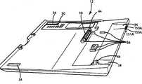
Being combined in shown in Fig. 1 and 2 A-B of portable computer and wireless power adapter according to an embodiment of the invention, and be represented as 10 usually.Wireless power adapter 12 comprises and is used for wirelessly receiving electric power and the power conversions that is used for receiving becomes to be applicable to the internalelectronic device 16 of the electric power of computing machine 14 (seeing Fig. 5 A) from long-range induction power supply.Shown in Fig. 3 and 4,wireless power adapter 12 comprises and is used for supplying electric power by the electric connector (not shown) to computingmachine 14 that this electric connector is provided at and is used on thecomputing machine 14 being connected with the Docking station (not shown).Refer again to Fig. 3 and 4,wireless power adapter 12 can comprise mechanical connector 20, and can use the mechanical connector (not shown) to be installed to the bottom surface ofcomputing machine 14, this mechanical connector is provided at and is used on thecomputing machine 14 being connected with the Docking station (not shown).
The present invention is in conjunction with being arranged to and Lenovo The wireless power adapter of laptop computer interface is described.Therefore, the present invention is connected to Lenovo in conjunction with being applicable to
 The electric connector and the mechanical connector of laptop computer are described.Shown wireless adapter also is configured at size and vpg connection and Lenovo
 The laptop computer correspondence.The present invention can easily be applicable to any other portable computer basically and use.For example, wireless adapter can be modified to incorporate into and be applicable to the electric connector and the mechanical connector of any other portable computer basically.The present invention can also be reset size and reset shape with any other portable computer is corresponding basically.


II. wireless power adapter
With reference now to Fig. 5 A and 5B,, internalelectronic device 16 generally includes secondary 24 (secondary) that are used for producing in response to induction field electric power will become to be applicable to the power supplysupplies electrons device 26 that the form of electric power is provided forcomputing machine 14 in secondary 24 power conversions that produce with being used for.Secondary 24 can be coil (such as twisted wire), shown in Fig. 5 A.Alternatively, secondary 24 can be any other parts that can produce electric power under the situation that suitable induction field exists.In one embodiment, coil secondary 24 can be replaced by printed circuit board coil, such as having comprised the United Statesserial 60/975 that is entitled as " printed circuit board coil (Printed Circuit Board Coil) " that people such as Baarman submitted on September 28th, 2007, the printed circuit board coil of 953 inventive principle, this paper is incorporated herein by reference it in full.Printed circuit board coil can provide a plurality of advantages.For example, printed circuit board coil can allow to use thinner coil and therefore reduce the general thickness of adapter 12.Printed circuit board coil can also improve the efficient of wireless power transmission and reduce the overall cost ofsystem 10.
If necessary, the present invention can utilize the induction charging system, this induction charging system is included in the communication link between theelectron device 16 ofadapter 12 and the electron device of long-range induction power supply (for example,electron device 54 in thebase 40 or theelectron device 102 in thedesktop 100).This communication link can be used to provide from the information of adapter with the appropriate ofpromotion system 10 and effectively operation to long-range induction power supply.For example, the induction power supply system that utilizes such communication link is in the United States serial of being submitted on January 7th, 2008 by people such as Baarman 61/019 that is entitled as " induction power supply (Inductive Power Supply with DutyCycle Control) that has dutycycle control ", be described in 411, and this paper is incorporated herein by reference it in full.In shown embodiment,adapter 12 comprises two infrared transmitters 150, and this infrared transmitter 150 is used for to transmit voltage and current information with United States serial 61/019,411 corresponding to mode to remote power supply by the controller in the adapter 12.Two transmitter 150a-b are connected in parallel and two different positions are provided, and remote power supply can receive the message (communication) fromadapter 12 from these two different positions.The first transmitter 150a is positioned at the rear ofhousing 22 so that rear IR transmitter (seeing Fig. 3 and 5A) to be provided.As illustrating typically among Fig. 3, the first transmitter 150a can be installed tohousing 22 and be in the window 151a that is hidden by infrared lenses 153a.The first transmitter 150a in Fig. 5 A the part as seen.The first transmitter 150a provides and is applicable to the communication transmitter that transmits message to followingdesktop 100 well.Thesecond transmitter 150b (only being illustrated typically in Fig. 3) is installed to thebottom 32 ofadapter 12 so that bottom IR transmitter to be provided.Thesecond transmitter 150b can be installed tobottom 32 and be in thewindow 151b that is hidden by infrared lenses 153b.Thesecond transmitter 150b is applicable to well to followingbase 40 provides infrared ray message.The quantity of transmitter and position can change with the change of using as required.Although show the present invention by infrared communication link, the present invention can comprise other wireless communication technology that is used for the information fromadapter 12 is sent to long-range induction power supply.In an alternative embodiment, can be by using as United States serial 61/019, the described existing primary and secondary of 411 (being identified hereinbefore) transmits the message to long-range induction power supply, and this United States serial 61/019411 is incorporated in this as mentioned above by reference in full.In this was selected, long-range induction power supply (for example,electron device 54 in thebase 40 and theelectron device 102 in the desktop 100) can comprise the current sensor (not identifying with reference number) of the electric current variation that is used for the sensing tank circuit.Briefly,adapter 12 can comprise load electronic circuit (not identifying with reference number), and this load electronic circuit can be enabled or stop using optionally to increase the current drain (current draw) in the adapter 12.The current drain that increases is sent back to long-range induction power supply with the form of the reflected impedance that increases by (inherently) inherently.By optionally enabling and inactive load electronic circuit,adapter 12 can cause spike (spike) in reflected impedance.These spikes can be controlled to provide the data stream in the reflected impedance that is embedded in adapter 12.This data stream can comprise the information about the voltage and current in the adapter 12.Long-range induction power supply can comprise controller (not identifying with reference number), and this controller can be explained the data-message that is embedded in the variation of tank circuit electric current.For example, long-range induction power supply can comprise in tank circuit (not identifying with reference number) that current sense transformer (not identifying with reference number) is to provide the signal of the reflected impedance of representing adapter 12.The output of current sense transformer can be analyzed to find embedded message by controller (not identifying with reference number).Near-field communication is communicated by letter with other RF and also can be used, as by Baarman shown in the United Statesserial 10/689148 of being entitled as of being submitted on October 20th, 2003 " induction power supply (Adaptive InductivePower Supply with Communication) that adapts to communication ", it is incorporated in this in full by reference.
In shown embodiment,source electronics 26 is connected to the power pin 28a-b of theelectric connector 18 of adapter.For provide withcomputing machine 14 on the compatibility of Docking station connector of preexist,source electronics 26 can be fixed to the Docking station electric connector (not shown) that formerly exists on the corresponding pin 28a-b of power pin.As may be best illustrating like that among Fig. 5 A and the 5B, shown embodiment comprises the live line 29a that is connected to charged pin 28a and is connected to the ground wire 29b of grounding pin 28b.Power pin 28a-b can change with the change of using.For example, be arranged to except Lenovo The
Thewireless power adapter 12 that computing machine in addition uses together can utilize different electric connectors and different pin arrangement.

In addition, some computing machines comprise the charger identification mechanism, are intended to prevent the electric power of computing machine acceptance from the electric power source that does not have suitable sign.In the illustrated embodiment,computing machine 14 comprises sign pin (not shown) in computing machine Docking station electric connector (not shown).In order to provide suitable id signal by adapterelectric connector 18 to computingmachine 14,line 120 is connected to ground 122 (seeing Fig. 5 B) byresistor 124 from sign pin (not shown).The suitable response that provides the electric power that is put on sign pin (not shown) bycomputing machine 14 is provided the value of rheostat 124.The various computing machine may need different signs or verification component, and the present invention can easily be applicable to and comprises any basically needed sign or verification component.
As mentioned above,wireless power adapter 12 can also comprise the mechanical connector 20 that is used forwireless power adapter 12 andcomputing machine 14 mechanical interconnection.In shown embodiment, this mechanical connector 20 comprises a pair ofdoor bolt 44 that is integrated in the housing 22.Thedoor bolt 44 can be spring and hole (not shown) that be arranged to the correspondence on the bottom ofcomputing machine 14 in fasten.As shown in Figure 5, eachdoor bolt 44 can compriseslide bar 46 and spring 48.Slide bar 46 is fixed in the track in thehousing 22 and can touches (accessible) (seeing Fig. 2 B) from the bottom of adapter 12.Bar 46 be configured to make head on spring biasing (spring-bias) manually slidingbar 46door bolt 44 andcomputing machine 14 are broken away from, thereby allowadapter 12 easily to be removed from computing machine 14.Although shown embodiment comprises two independentlyslide bars 46,adapter 12 can alternatively be assembled single bar and operate two door bolts 44.Mechanical connector 20 can change with the change of using as required.Have the application that is used forcomputing machine 14 is fixed to the pre-configured mechanical connector of Docking station atcomputing machine 14,wireless power adapter 12 can comprise the mechanical connector of coupling.If necessary, mechanical connector 20 can comprise frictional fit (friction fit) betweenadapter 12 and computing machine 14.Term " mechanical connector " is intended to comprise any structure that is used to makewireless power adapter 12 andcomputing machine 14 physical interconnections, and is not limited to entirely mechanical structure.For example, mechanical connector can comprise magnet, electromagnet and other parts that may not can on the letter of strictness be counted as " machinery ".
In addition,wireless power adapter 12 can comprise one or more fitment port, plug or socket, such as USB port, monitor socket, mouse port, CAT 5 jacks, modulator-demodular unit socket, earphone jack and microphone jack.These fitment port, plug, jack and socket can be merged in the substantially the same mode of existing Docking station with them and be merged inhousing 22 and be connected to adapter docking port electrical connector 18.For example, the USB port that is merged inadapter 12 can be connected to the pin (not shown) that is used on theelectric connector 18 that the USB port on the Docking station uses together.Therefore, port, plug, jack and socket will allow accessory to be connected to computingmachine 14 by suitable portable computer docks port connector pin (not shown).
III. the radio source supply
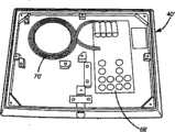
As mentioned above,wireless power adapter 12 can be arranged to from being applicable to any basically long-range induction power supply reception electric power with internalelectronic device 16 uses of adapter 12.In the embodiment of Fig. 6-11,wireless power adapter 12 is illustrated with private radio power supply base 40.Base 40 generally includeshousing 52 and power circuit 54.Shownhousing 52 aim to provide the combination that can holdadapter 12/computing machine 14 and rely on desktop or other stayed surface on low type base.The profile at the top ofhousing 52 can be followed the shape of the bottom surface of adapter 12.For example,housing 52 can define therecess 56 of thepin 33 that is used to hold adapter 12.This recess 56 and/or other profile can be aimed at the valid function that is used to promote system by providing betweenadapter 12 and base 40 (and therefore elementary 70 and secondary 24).In shown embodiment,housing 52 extends on an equal basis withadapter 12 basically, extends the total length of aboutcomputing machine 14 and wide.But the size ofhousing 52 can change with the change of using as required.Housing 52 can define the air vent (not shown) and help to reduce the thermal accumlation that is associated with source electronics 54.Theinner space 60 thathousing 52 can define sufficient size and shape comprises source electronics 54.Housing 52 can comprise thebottom 62 that is used to makeinner space 60closures.Bottom 62 can be removable, for example, and by screw or other securing member (not identifying) withreference number.Bottom 62 can defineair vent 64 and spill in thespace 60 internally to allowheat.Bottom 62 can comprise pin 66.The size ofhousing 52, shape and configuration (comprising bottom 62) can change with the change of using as required.
Internalelectronic device 54 generally includes the inductionpower supply circuit 68 that is used to produce inductionfield.Power circuit 68 can comprise any basically electron device that can produce induction field.In shown embodiment,power circuit 68 can comprise controller (not identifying with reference number), driver (not identifying with reference number), switch electronic circuit (not identifying with reference number) usually and have elementary 70 tank circuit (not identifying with reference number).Elementary 70 in Figure 11 A not exclusively as seen, but basically elementary 70 ' of unanimity in Figure 11 B as seen.Figure 11 B is the base 40 ' that substitutes with some power circuits 68 ' different with Figure 11 A.Comprise that Figure 11 B illustrates elementary 70 ' the Position Approximate inhousing 52 '.Elementary 70 can be coil (for example, twisted wire), shown in Figure 11 B.Alternatively, elementary 70 can be any other parts that can produce suitable induction field.In one embodiment, coil elementary 70 can be replaced by printed circuit board coil, as mentioned in conjunction with secondary 24 discussed like that.
As mentioned above, may it is desirable to use power-supply system, this power-supply system is included in, and resonance disclosed in the United States Patent (USP) 6,825,620 of authorizing people such as Kuennen, the induction power supply system is sought ability; Authorize the adaptive inductive power supply of people's such as Baarman United States Patent (USP) 7,212,414; Authorize the adaptive inductive power supply of people's such as Baarman United Statesserial 10/689,148; The induction power supply that perhaps has the control of frequency and dutycycle is such as disclosed such in United States serial 61/019,411 (being identified hereinbefore).In shown embodiment,adapter 12 and long-range induction power supply comprise the induction power supply with frequency and dutycycle control.This system comprises the infrared communication link that is used for voltage and/or current information are sent to fromadapter 12 long-range induction power supply.Shown as Figure 11 A, transmit with the transmitter (not shown) receiving infrared-ray from thebottom 32 ofadapter 12 at the top that infrared receiver 160 (below insulating tape (beneath tape)) can be installed in housing 52.Receiver 160 can be installed in thewindow 161 in thehousing 52 and byinfrared lenses 163 and hide, and it is illustrated in Fig. 9 typically.In shown embodiment, internalelectronic device 54 is from receiving DC electric power such as external AC to the external power source (not shown) of DC power supply.Can external power be supplied to internal electronic device 54 (seeing Figure 11 A) by supply hub 67.External power source can alternatively directly be incorporated into internal electronic device 54.Should be noted that AC can be merged in the main base (primary base) with direct AC line to the DC power supply.This can replace described in connection with the embodiment AC to the DC power supply.
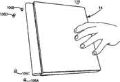
Figure 12-14 illustrates the long-range induction power supply that is merged in desktop 100.Induction desktop 100 allows electric power wirelessly to be supplied to adapter 12 and not need independently to respond to base, and for example base 40.In shown embodiment,desktop 100 definition are arranged to the inner space 108 (seeing Figure 12) that receives induction power supply circuit 102.Inner space 108 is closed (seeing Figure 13 and 14) by top panel 110.Inductionpower supply circuit 102 comprises inductive primary 104.Power circuit 102 can be consistent basically withbase 40 with elementary 104, and therefore will can not gone through.
With reference now to Figure 13 and 14,,desktop 100 can include and help elementary relatively 104 and locate secondary 24 steady arm pin 106a-d rightly.Go out as shown like that, the combination ofadapter 12/computing machine 14 can be installed in place to guarantee appropriate aligning in steady arm pin 106a-d.Steady arm pin 106a-d can also have other function.For example, steady arm pin 106a-d can serve as light pipe.In shown embodiment,power circuit 102 can comprise the LED (not shown), and this LED is lighted to provide status information to the user.Pair of LEDs can be positioned in below the steady arm pin 106a-b, and feasible light fromLED passes desktop 100 and makes steady arm pin 106a-b luminous.Two LED can be lighted or LED can be lighted to indicate different status conditions respectively according to identical status condition.For example, when electric power was supplied toadapter 12, two blue leds can be used to make steady arm pin 106a-b blue light-emitting.Alternatively, the LED of different colours can be used to indicate different status conditions.When for example, blue led can be used to indicate electric power and is supplied toadapter 12 and red LED can be used to indicate fault condition.Steady arm pin 106a-d can also be used to infrared ray message is routed topower circuit 102 from adapter 12.For example, the steady arm pin 106c infrared transmitter 150a that can be positioned in the rear ofadjacent adapter housing 22 extends.Steady arm twines pin 106c can be from infrared transmitter 150 collection infrared signals and with the infrared receiver (not shown) of its carrying below being installed indesktop 100.
Above-mentioned explanation is the explanation to current embodiment of the present invention.Can carry out various changes and variation and do not break away from the appended claim of defined in the appended claims spirit of the present invention and wideer aspect will be according to comprising that being equal to theoretical Patent Law principle explains.To the quoting of the element of claim, for example use article " ", " being somebody's turn to do " or " described " with singulative, should not be considered to element is defined as single.
Claims (20)
- Proprietary characteristic or privilege are declared in an embodiment of the present invention, and described embodiments of the invention are defined as follows:1. radio source that is used to have the portable computer of Docking station port, it comprises:The adapter housing;Wireless power receiver, described wireless power receiver are disposed on the described housing or are used in the described housing wirelessly receiving electric power from the external wireless power supply; AndDocking port electrical connector, described docking port electrical connector be installed to described housing and be arranged to optionally with described portable computer on Docking station port interfaces, described docking port electrical connector has the electric power pin that receives electric power at least indirectly from described wireless power receiver.
- 2. radio source as claimed in claim 1, wherein said wireless power receiver is further defined as inductive secondary.
- 3. radio source as claimed in claim 2, wherein said adapter comprise at least one of power regulation circuit that is used for changing the power conversion circuit of the electric power that produces at described wireless power receiver and is used for being adjusted in the electric power that described wireless power receiver produces.
- 4. radio source as claimed in claim 1, wherein said portable computer comprises the mechanical connector that is used for described portable computer is mechanically secured to Docking station; AndAlso comprise the radio source mechanical connector, described radio source mechanical connector can interconnect releasedly with the described mechanical connector on the described portable computer, and wherein said radio source can optionally be mechanically connected to described portable computer.
- 5. radio source as claimed in claim 4, wherein said radio source mechanical connector is further defined as between the primary importance and the second place movably at least one door bolt, the described corresponding mechanical connector that is latched on primary importance and the described portable computer engages, and breaks away from described corresponding mechanical connector in the second place.
- 6. radio source as claimed in claim 5, wherein said door bolt is operably connected to the chute of user-operable, and the chute of described user-operable optionally moves described door bolt between the described primary importance and the described second place.
- 7. radio source as claimed in claim 1, it also comprises at least one fitment port, plug or socket, described at least one fitment port, plug or socket be coupled to described docking port electrical connector with the interconnection of suitable computing machine craft port connector pin.
- 8. radio source as claimed in claim 1, it also comprises the communication transmitter that is used for transmitting to radio source power information.
- 9. radio source as claimed in claim 1 also comprises a plurality of communication transmitters that are used for transmitting to radio source power information.
- 10. combination, it comprises:Radio source with inductive primary, described power supply comprise and are used for to the described elementary circuit that applies electric power the wherein said elementary electromagnetic field that changes;Has the portable computer that is arranged to optionally with the Docking station port of Docking station interfaces; AndBe installed to the adapter of described portable computer removedly, described adapter can be placed in the electromagnetic field of described variation removedly, described adapter has the inductive secondary that is used for receiving from described power supply wireless ground by the electromagnetic field of described variation electric power, described adapter has the docking port electrical connector that the described Docking station port with described portable computer cooperatively interacts removedly, and described adapter has and is used for by described docking port electrical connector and described Docking station port the circuit that is sent to described portable computer at the electric power of described secondary generation.
- 11. combination as claimed in claim 10, wherein said portable computer comprises mechanical connector, described mechanical connector be arranged to Docking station on corresponding mechanical connector optionally mechanically interconnected; AndWherein, described adapter comprises the mechanical connector that the described mechanical connector with described portable computer interconnects removedly.
- 12. combination as claimed in claim 11, wherein said adapter comprise at least one of power regulation circuit that is used for changing the power conversion circuit of the electric power that produces at described wireless power receiver and is used for being adjusted in the electric power that described wireless power receiver produces.
- 13. combination as claimed in claim 10, it also is included in the wireless communication link between described power supply and the described adapter.
- 14. combination as claimed in claim 10, it also is included in the wireless communication link between described power supply and the described adapter, and described adapter comprises at least two communication transmitters that are disposed in the diverse location place.
- 15. combination as claimed in claim 10, wherein said adapter comprises at least one fitment port, plug or socket, described at least one fitment port, plug or socket be coupled to described docking port electrical connector with the interconnection of suitable computing machine craft port connector pin.
- 16. combination as claimed in claim 10, wherein said radio source is disposed in the charging base, described base has upper surface, described adapter can be placed on the described upper surface removedly wirelessly to receive electric power, and the profile of the described upper surface of described base is corresponding with the bottom surface of described adapter.
- 17. a method that is used for wirelessly supplying to the portable computer with Docking station port electric power, it may further comprise the steps:Adapter and described portable computer are cooperatively interacted, and described adapter has wireless power receiver and docking port electrical connector, and described docking port electrical connector is electrically coupled to the electric power pin in the Docking station port on described portable computer;The electromagnetic field that changes by radio source;Described adapter is placed in the electromagnetic field of described variation, wherein said wireless power receiver produces electric power in response to the electromagnetic field of described variation; AndTo put on described portable computer by the electric power that described wireless power receiver produces by the electric power pin in described docking port electrical connector and the Docking station port on described portable computer.
- 18. method as claimed in claim 17, it also comprises described adapter and the mechanically interconnected step of described portable computer.
- 19. method as claimed in claim 18, it also is included in the described step that applies will be become be applicable to the step of the form of described portable computer by the power conversions that described wireless power receiver produces before.
- 20. method as claimed in claim 19, it is further comprising the steps of:Power information is sent to described radio source from described adapter; AndChange at least one feature of the electromagnetic field of described variation in response to the power information that receives by described radio source.
Applications Claiming Priority (3)
| Application Number | Priority Date | Filing Date | Title |
|---|---|---|---|
| US1937708P | 2008-01-07 | 2008-01-07 | |
| US61/019377 | 2008-01-07 | ||
| PCT/US2009/030246WO2009089233A1 (en) | 2008-01-07 | 2009-01-07 | Wireless power adapter for computer |
Publications (1)
| Publication Number | Publication Date |
|---|---|
| CN101910968Atrue CN101910968A (en) | 2010-12-08 |
Family
ID=40317053
Family Applications (1)
| Application Number | Title | Priority Date | Filing Date |
|---|---|---|---|
| CN2009801020546APendingCN101910968A (en) | 2008-01-07 | 2009-01-07 | Wireless power adapter for computer |
Country Status (10)
| Country | Link |
|---|---|
| US (1) | US8127155B2 (en) |
| EP (1) | EP2229614A1 (en) |
| JP (1) | JP2011509467A (en) |
| KR (1) | KR20100095006A (en) |
| CN (1) | CN101910968A (en) |
| AU (1) | AU2009204263A1 (en) |
| CA (1) | CA2705932A1 (en) |
| RU (1) | RU2010133056A (en) |
| TW (1) | TW200945723A (en) |
| WO (1) | WO2009089233A1 (en) |
Families Citing this family (40)
| Publication number | Priority date | Publication date | Assignee | Title |
|---|---|---|---|---|
| US20090243396A1 (en)* | 2008-03-03 | 2009-10-01 | Mitch Randall | Apparatus and method for retrofitting a broad range of mobile devices to receive wireless power |
| RU2011132944A (en) | 2009-01-06 | 2013-02-20 | Эксесс Бизнесс Груп Интернешнл Ллс | INDUCTIVE POWER SUPPLY |
| WO2012030473A2 (en)* | 2010-08-30 | 2012-03-08 | Hardcore Computer, Inc. | Server case with optical input/output and/or wireless power supply |
| RU2010136667A (en)* | 2010-09-02 | 2012-03-10 | Владимир Витальевич Мирошниченко (RU) | METHOD OF POWER SUPPLY OF TECHNICAL MEANS OF THE DEVICE |
| JP5728949B2 (en)* | 2011-01-06 | 2015-06-03 | 富士通株式会社 | Second device |
| US20120244969A1 (en) | 2011-03-25 | 2012-09-27 | May Patents Ltd. | System and Method for a Motion Sensing Device |
| CN102736685A (en)* | 2011-04-12 | 2012-10-17 | 英业达股份有限公司 | Portable computer |
| CN103649866B (en) | 2011-06-30 | 2019-10-18 | 惠普发展公司,有限责任合伙企业 | The latch and panel of computing system |
| US8553408B2 (en) | 2011-09-06 | 2013-10-08 | Dana Innovations | Charging docking system |
| JP5906919B2 (en)* | 2012-04-23 | 2016-04-20 | 富士通株式会社 | Support device |
| US9538313B2 (en)* | 2012-08-23 | 2017-01-03 | Intel Corporation | Apparatus, system and method of docking a mobile device with wireless connector |
| US9125289B2 (en) | 2012-10-05 | 2015-09-01 | Javid Vahid | Asymmetric computer tablet frame docking system |
| US9337661B2 (en)* | 2012-12-27 | 2016-05-10 | Intel Corporation | Power management system and method |
| US20140187289A1 (en)* | 2013-01-03 | 2014-07-03 | Headlogic Llc | Modular Components and Methods for an Electronic Device |
| US20150016051A1 (en)* | 2013-07-15 | 2015-01-15 | Toshiba Global Commerce Solutions Holdings Corporation | Display assembly having graduated magnetic fastening characteristics |
| US10429889B2 (en)* | 2013-08-08 | 2019-10-01 | Dell Products L.P. | Information handling system docking with coordinated power and data communication |
| US9377814B2 (en) | 2013-08-08 | 2016-06-28 | Dell Products L.P. | Information handling system docking with coordinated power and data communication |
| US9304545B2 (en) | 2013-08-08 | 2016-04-05 | Dell Products L.P. | Information handling system docking with coordinated power and data communication |
| US10664772B1 (en) | 2014-03-07 | 2020-05-26 | Steelcase Inc. | Method and system for facilitating collaboration sessions |
| US9716861B1 (en) | 2014-03-07 | 2017-07-25 | Steelcase Inc. | Method and system for facilitating collaboration sessions |
| US9729201B2 (en)* | 2014-04-24 | 2017-08-08 | Empire Technology Development Llc | Broadcasting a message using modulated power |
| US9766079B1 (en) | 2014-10-03 | 2017-09-19 | Steelcase Inc. | Method and system for locating resources and communicating within an enterprise |
| US9955318B1 (en) | 2014-06-05 | 2018-04-24 | Steelcase Inc. | Space guidance and management system and method |
| US9380682B2 (en) | 2014-06-05 | 2016-06-28 | Steelcase Inc. | Environment optimization for space based on presence and activities |
| US10614694B1 (en) | 2014-06-06 | 2020-04-07 | Steelcase Inc. | Powered furniture assembly |
| US11744376B2 (en) | 2014-06-06 | 2023-09-05 | Steelcase Inc. | Microclimate control systems and methods |
| US10433646B1 (en) | 2014-06-06 | 2019-10-08 | Steelcaase Inc. | Microclimate control systems and methods |
| US9793744B2 (en) | 2014-09-12 | 2017-10-17 | Robert Bosch Tool Corporation | Interface and mounting structure for a wireless charger or intermediate piece |
| US9852388B1 (en) | 2014-10-03 | 2017-12-26 | Steelcase, Inc. | Method and system for locating resources and communicating within an enterprise |
| USD854012S1 (en)* | 2014-12-26 | 2019-07-16 | Intel Corporation | Electronic device with wireless dock slots |
| US9430001B2 (en)* | 2015-01-05 | 2016-08-30 | Microsoft Technology Licensing, Llc | Modular computing device |
| US10733371B1 (en) | 2015-06-02 | 2020-08-04 | Steelcase Inc. | Template based content preparation system for use with a plurality of space types |
| US10788856B2 (en) | 2015-11-24 | 2020-09-29 | Intel Corporation | Docking station |
| US9921726B1 (en) | 2016-06-03 | 2018-03-20 | Steelcase Inc. | Smart workstation method and system |
| US10264213B1 (en) | 2016-12-15 | 2019-04-16 | Steelcase Inc. | Content amplification system and method |
| US10198037B2 (en) | 2017-02-07 | 2019-02-05 | Case Byte Technology, Llc | Low profile auxiliary component mounting article |
| US10283952B2 (en) | 2017-06-22 | 2019-05-07 | Bretford Manufacturing, Inc. | Rapidly deployable floor power system |
| US10976783B2 (en)* | 2019-02-04 | 2021-04-13 | Ralph Belfiglio | Low profile auxiliary component mounting article |
| US12118178B1 (en) | 2020-04-08 | 2024-10-15 | Steelcase Inc. | Wayfinding services method and apparatus |
| US11984739B1 (en) | 2020-07-31 | 2024-05-14 | Steelcase Inc. | Remote power systems, apparatus and methods |
Family Cites Families (102)
| Publication number | Priority date | Publication date | Assignee | Title |
|---|---|---|---|---|
| GB210886A (en) | 1922-11-11 | 1924-02-11 | Cecil Hughes | Improvements in and relating to fuel-delivery pumps for internal combustion engines |
| GB213024A (en) | 1923-01-04 | 1924-03-27 | Kenneth Lewin Weber | Process of making flexible, non-breakable, transparent and water-proof panes and other articles |
| GB213374A (en) | 1923-01-30 | 1924-04-03 | Charles Samuel Townsend | Improvements in or relating to cartons and means for displaying articles for sale |
| GB225006A (en) | 1923-09-26 | 1924-11-27 | Arthur Drummond | Improvements in or relating to power driven saws |
| GB228425A (en) | 1924-06-19 | 1925-02-05 | Jenkin Jones | Improvements in or relating to hack saw frames |
| US3689885A (en) | 1970-09-15 | 1972-09-05 | Transitag Corp | Inductively coupled passive responder and interrogator unit having multidimension electromagnetic field capabilities |
| US3949268A (en) | 1971-02-11 | 1976-04-06 | Burkhard Von Mangoldt | Ballast unit for gas discharge lamps such as fluorescent tubes or the like |
| US3938018A (en) | 1974-09-16 | 1976-02-10 | Dahl Ernest A | Induction charging system |
| US6075340A (en) | 1985-11-12 | 2000-06-13 | Intermec Ip Corp. | Battery pack having memory |
| US4818855A (en) | 1985-01-11 | 1989-04-04 | Indala Corporation | Identification system |
| US4800328A (en) | 1986-07-18 | 1989-01-24 | Inductran Inc. | Inductive power coupling with constant voltage output |
| US5814900A (en) | 1991-07-30 | 1998-09-29 | Ulrich Schwan | Device for combined transmission of energy and electric signals |
| US5341280A (en) | 1991-09-27 | 1994-08-23 | Electric Power Research Institute | Contactless coaxial winding transformer power transfer system |
| GB2262634B (en) | 1991-12-18 | 1995-07-12 | Apple Computer | Power connection scheme |
| GB9204200D0 (en) | 1992-02-27 | 1992-04-08 | Goble Nigel M | An inductive loop power transmission system |
| EP0561309B1 (en) | 1992-03-16 | 1997-05-28 | Eastman Kodak Company | Device for transferring electrical signals and electric energy to the memory device of a cassette |
| US5229652A (en) | 1992-04-20 | 1993-07-20 | Hough Wayne E | Non-contact data and power connector for computer based modules |
| JPH065231A (en) | 1992-06-23 | 1994-01-14 | Sony Corp | Convergence correcting device |
| JP3011829B2 (en) | 1993-06-30 | 2000-02-21 | 株式会社ケンウッド | Method and apparatus for manufacturing speaker |
| JP3409145B2 (en) | 1993-07-26 | 2003-05-26 | 任天堂株式会社 | Small electrical equipment |
| US5455466A (en) | 1993-07-29 | 1995-10-03 | Dell Usa, L.P. | Inductive coupling system for power and data transfer |
| JP2671809B2 (en) | 1994-06-30 | 1997-11-05 | 日本電気株式会社 | Non-contact charging device |
| JPH10506208A (en) | 1994-07-19 | 1998-06-16 | エロネックス・テクノロジーズ・インコーポレーテッド | Micro personal digital assistant |
| JP3011829U (en) | 1994-07-27 | 1995-06-06 | 株式会社三岡電機製作所 | Power supply connection device for charging |
| WO1996018940A1 (en) | 1994-12-16 | 1996-06-20 | Elonex Technologies, Inc. | Management of data before zero volt suspend in computer power management |
| US5982764A (en) | 1995-05-18 | 1999-11-09 | Aura Communications, Inc. | Time-multiplexed short-range magnetic communications |
| JPH09190938A (en) | 1996-01-09 | 1997-07-22 | Tdk Corp | Non-contact type battery charger |
| JP3469699B2 (en)* | 1996-02-20 | 2003-11-25 | インターナショナル・ビジネス・マシーンズ・コーポレーション | Docking device for portable computer |
| DE19621076C2 (en) | 1996-05-24 | 2001-06-28 | Siemens Ag | Device and method for the contactless transmission of energy or data |
| JPH09326736A (en) | 1996-06-03 | 1997-12-16 | Mitsubishi Electric Corp | Secondary side circuit device for wireless transmission / reception system and induction coil for wireless transmission / reception system |
| US5734254A (en) | 1996-12-06 | 1998-03-31 | Hewlett-Packard Company | Battery pack and charging system for a portable electronic device |
| JP2990083B2 (en) | 1996-12-27 | 1999-12-13 | 静岡日本電気株式会社 | Mobile communication antenna device |
| JP4067595B2 (en) | 1997-02-20 | 2008-03-26 | 富士通株式会社 | Non-contact charging device compatible with multiple devices |
| US7068991B2 (en) | 1997-05-09 | 2006-06-27 | Parise Ronald J | Remote power recharge for electronic equipment |
| AU3046297A (en) | 1997-06-16 | 1999-01-04 | Yehuda Binder | Battery substitute pack |
| US6837435B2 (en) | 1997-06-26 | 2005-01-04 | Symbol Technologies, Inc. | Adapter unit having a handle grip for a personal digital assistant |
| DE19735624C1 (en) | 1997-08-18 | 1998-12-10 | Daimler Benz Ag | Method of inductive transfer of electrical power to several moving loads |
| DE19735685A1 (en) | 1997-08-19 | 1999-02-25 | Wampfler Ag | Non contact electrical energy transmission device for personal vehicle |
| US5959433A (en) | 1997-08-22 | 1999-09-28 | Centurion Intl., Inc. | Universal inductive battery charger system |
| JPH11168837A (en) | 1997-10-01 | 1999-06-22 | Casio Comput Co Ltd | Charger for mobile communication equipment |
| US6275681B1 (en) | 1998-04-16 | 2001-08-14 | Motorola, Inc. | Wireless electrostatic charging and communicating system |
| JP3180086B2 (en) | 1998-08-31 | 2001-06-25 | 株式会社シーメディア | Mobile communication device, information transmission system and method, non-contact IC media usable in mobile communication device |
| DE29816725U1 (en) | 1998-09-17 | 1999-01-14 | Chao, Wen-Chung, Yungho, Taipeh | Charging device for mobile phones |
| JP2000166112A (en) | 1998-11-27 | 2000-06-16 | Matsushita Electric Ind Co Ltd | Charger for mobile information terminal device and mobile information terminal device |
| TW463399B (en) | 1999-03-19 | 2001-11-11 | Seiko Epson Corp | Electronic device |
| JP2000287375A (en) | 1999-03-29 | 2000-10-13 | Japan Storage Battery Co Ltd | Charging circuit for secondary battery |
| US6127799A (en) | 1999-05-14 | 2000-10-03 | Gte Internetworking Incorporated | Method and apparatus for wireless powering and recharging |
| AU4926700A (en) | 1999-06-11 | 2001-01-02 | Abb Research Ltd | Method and assembly for the wireless supply of electric energy to a number of actuators, actuator and primary winding therefor and system for a machine with a number of actuators |
| US7212414B2 (en)* | 1999-06-21 | 2007-05-01 | Access Business Group International, Llc | Adaptive inductive power supply |
| US7518267B2 (en) | 2003-02-04 | 2009-04-14 | Access Business Group International Llc | Power adapter for a remote device |
| US6825620B2 (en)* | 1999-06-21 | 2004-11-30 | Access Business Group International Llc | Inductively coupled ballast circuit |
| US6323775B1 (en) | 1999-08-10 | 2001-11-27 | Telefonaktiebolaget Im Ericsson (Publ) | Method, system and apparatus for proximity-based recharge notification |
| JP4089100B2 (en) | 1999-08-20 | 2008-05-21 | 株式会社デンソー | Mobile phone connection device |
| US6803744B1 (en) | 1999-11-01 | 2004-10-12 | Anthony Sabo | Alignment independent and self aligning inductive power transfer system |
| JP3539326B2 (en) | 1999-12-27 | 2004-07-07 | 日本電気株式会社 | Mobile device charging system |
| US6301128B1 (en) | 2000-02-09 | 2001-10-09 | Delta Electronics, Inc. | Contactless electrical energy transmission system |
| JP2001251207A (en) | 2000-03-07 | 2001-09-14 | Hitachi Ltd | Mobile phone |
| JP2001268823A (en) | 2000-03-16 | 2001-09-28 | Aichi Electric Co Ltd | Non-contact feeder system |
| EP1291999B1 (en) | 2000-04-13 | 2013-01-30 | Makita Corporation | Adapter for battery charger |
| JP2001352698A (en) | 2000-06-06 | 2001-12-21 | Funai Electric Co Ltd | Power controller, power control system, and electronic apparatus |
| FI116344B (en) | 2000-10-11 | 2005-10-31 | Nokia Corp | communication device |
| JP3580245B2 (en) | 2000-11-10 | 2004-10-20 | 日本電気株式会社 | Mobile terminal |
| US6429622B1 (en) | 2000-11-14 | 2002-08-06 | Telefonaktiebolaget L M Ericsson (Publ) | Method and apparatus for authenticating a charging unit by a portable battery-operated electronic device |
| FI20002493A7 (en) | 2000-11-14 | 2002-05-15 | Salcomp Oy | Power supply arrangement and inductively coupled battery charger with wirelessly coupled control, and method for wirelessly controlling the power supply arrangement and inductively coupled battery charger |
| JP2002199062A (en) | 2000-12-25 | 2002-07-12 | Hitachi Ltd | Portable terminal equipment |
| KR100566220B1 (en) | 2001-01-05 | 2006-03-29 | 삼성전자주식회사 | Solid state battery charger |
| KR20020057469A (en) | 2001-01-05 | 2002-07-11 | 윤종용 | A coreless low-profile pcb transformer and contactless battery charger using the pcb transformer |
| US20020090983A1 (en) | 2001-01-11 | 2002-07-11 | I-Ming Chen | Device for charging a battery unit of a mobile telephone handset |
| JP2002359676A (en) | 2001-05-31 | 2002-12-13 | Sanyodo:Kk | Mobile telephone and battery for the mobile telephone |
| CN2480996Y (en) | 2001-06-08 | 2002-03-06 | 徐跃进 | Solar energy recharger for mobile telephone lithium battery |
| TW542480U (en) | 2001-11-13 | 2003-07-11 | Yi Chang Hsiang Ind Co Ltd | Mobile phone battery |
| US6977479B2 (en) | 2002-01-08 | 2005-12-20 | Hsu Po-Jung John | Portable cell phone battery charger using solar energy as the primary source of power |
| GB2399466B (en) | 2003-03-10 | 2005-11-16 | Univ City Hong Kong | Battery charging system |
| GB0213374D0 (en) | 2002-06-10 | 2002-07-24 | Univ City Hong Kong | Planar inductive battery charger |
| US20030132731A1 (en) | 2002-01-14 | 2003-07-17 | Asoka Inc. | Contactless battery charging device |
| US7392068B2 (en) | 2002-03-01 | 2008-06-24 | Mobilewise | Alternative wirefree mobile device power supply method and system with free positioning |
| US6913477B2 (en) | 2002-03-01 | 2005-07-05 | Mobilewise, Inc. | Wirefree mobile device power supply method & system with free positioning |
| GB2388716B (en) | 2002-05-13 | 2004-10-20 | Splashpower Ltd | Improvements relating to contact-less power transfer |
| US6844702B2 (en) | 2002-05-16 | 2005-01-18 | Koninklijke Philips Electronics N.V. | System, method and apparatus for contact-less battery charging with dynamic control |
| US7679902B2 (en)* | 2002-05-28 | 2010-03-16 | Eric Thompson | Vertical docking station |
| EP2479866B1 (en) | 2002-06-10 | 2018-07-18 | City University of Hong Kong | Planar inductive battery charger |
| GB0213375D0 (en) | 2002-06-10 | 2002-07-24 | Univ City Hong Kong | Apparatus for energy transfer by induction |
| US7471062B2 (en) | 2002-06-12 | 2008-12-30 | Koninklijke Philips Electronics N.V. | Wireless battery charging |
| TW200419966A (en) | 2002-08-12 | 2004-10-01 | Mobilewise Inc | Enhanced RF wireless adaptive power provisioning system for small devices |
| US20040131928A1 (en) | 2002-09-17 | 2004-07-08 | Tal Dayan | Modifying surfaces of devices to integrate them into wireless charging systems |
| US7440780B2 (en) | 2002-09-18 | 2008-10-21 | University Of Pittsburgh - Of The Commonwealth System Of Higher Education | Recharging method and apparatus |
| US6756765B2 (en) | 2002-10-08 | 2004-06-29 | Koninklijke Philips Electronics N.V. | System and method for charging users to recharge power supplies in portable devices |
| TW200419332A (en) | 2002-10-18 | 2004-10-01 | Mobilewise Inc | Small geometry pads and system for wireless power supply |
| US20040142726A1 (en) | 2002-11-01 | 2004-07-22 | Tal Dayan | Method for controlling and interacting with a mobile device |
| GB0229141D0 (en) | 2002-12-16 | 2003-01-15 | Splashpower Ltd | Improvements relating to contact-less power transfer |
| US7117010B2 (en) | 2003-05-29 | 2006-10-03 | Cingular Wireless Ii, Llc | Wireless phone powered inductive loopset |
| US7375493B2 (en)* | 2003-12-12 | 2008-05-20 | Microsoft Corporation | Inductive battery charger |
| US7378817B2 (en) | 2003-12-12 | 2008-05-27 | Microsoft Corporation | Inductive power adapter |
| JP3736641B2 (en)* | 2004-01-22 | 2006-01-18 | セイコーエプソン株式会社 | Data transfer control device and electronic device |
| US20070072474A1 (en)* | 2005-04-27 | 2007-03-29 | Nigel Beasley | Flexible power adapter systems and methods |
| US7548040B2 (en) | 2005-07-28 | 2009-06-16 | Zerog Wireless, Inc. | Wireless battery charging of electronic devices such as wireless headsets/headphones |
| US7352567B2 (en)* | 2005-08-09 | 2008-04-01 | Apple Inc. | Methods and apparatuses for docking a portable electronic device that has a planar like configuration and that operates in multiple orientations |
| US8447234B2 (en) | 2006-01-18 | 2013-05-21 | Qualcomm Incorporated | Method and system for powering an electronic device via a wireless link |
| US7952322B2 (en) | 2006-01-31 | 2011-05-31 | Mojo Mobility, Inc. | Inductive power source and charging system |
| US20070259554A1 (en)* | 2006-05-04 | 2007-11-08 | Ergotron, Inc. | Stand system and method |
| KR100836634B1 (en) | 2006-10-24 | 2008-06-10 | 주식회사 한림포스텍 | Portable terminal using a contactless charger, a battery pack for charging and a contactless charger for wireless data communication and power transmission |
| US7986059B2 (en) | 2008-01-04 | 2011-07-26 | Pure Energy Solutions, Inc. | Device cover with embedded power receiver |
- 2009
- 2009-01-07CNCN2009801020546Apatent/CN101910968A/enactivePending
- 2009-01-07WOPCT/US2009/030246patent/WO2009089233A1/enactiveApplication Filing
- 2009-01-07TWTW098100300Apatent/TW200945723A/enunknown
- 2009-01-07CACA2705932Apatent/CA2705932A1/ennot_activeAbandoned
- 2009-01-07EPEP09700683Apatent/EP2229614A1/ennot_activeWithdrawn
- 2009-01-07AUAU2009204263Apatent/AU2009204263A1/ennot_activeAbandoned
- 2009-01-07JPJP2010541589Apatent/JP2011509467A/enactivePending
- 2009-01-07KRKR1020107015034Apatent/KR20100095006A/ennot_activeWithdrawn
- 2009-01-07USUS12/349,540patent/US8127155B2/enactiveActive
- 2009-01-07RURU2010133056/08Apatent/RU2010133056A/enunknown
Also Published As
| Publication number | Publication date |
|---|---|
| KR20100095006A (en) | 2010-08-27 |
| US8127155B2 (en) | 2012-02-28 |
| JP2011509467A (en) | 2011-03-24 |
| TW200945723A (en) | 2009-11-01 |
| EP2229614A1 (en) | 2010-09-22 |
| WO2009089233A1 (en) | 2009-07-16 |
| CA2705932A1 (en) | 2009-07-16 |
| RU2010133056A (en) | 2012-02-20 |
| AU2009204263A1 (en) | 2009-07-16 |
| US20090177908A1 (en) | 2009-07-09 |
Similar Documents
| Publication | Publication Date | Title |
|---|---|---|
| CN101910968A (en) | Wireless power adapter for computer | |
| US6498458B1 (en) | Battery charger for charging a wireless signal source and detachable receiver | |
| US11445626B2 (en) | Power outlet module including USB plug in location other than outlet face | |
| US8107243B2 (en) | Portable multi-device power supply, battery charger, and docking system | |
| CN201256186Y (en) | Cable and mooring arrangement | |
| AU2018201398B2 (en) | Battery packs and chargers, and battery pack kit for power tools | |
| US7591673B2 (en) | Combined power and control signal cable | |
| CN101432943B (en) | Power supply system | |
| US20080143185A1 (en) | System for Supplying Power for Peripheral Devices | |
| CN211405512U (en) | Adapter | |
| CN108718020A (en) | Concentrator | |
| JP2002182800A (en) | Computer system, method for operating peripheral equipment and computer peripheral equipment | |
| CN101447686A (en) | Power supply capable of detecting and adjusting voltage and current required by electronic product | |
| US12424877B2 (en) | Charging device | |
| US20150015492A1 (en) | Keyboard enabling inputting of position information and keyboard system comprising same | |
| US20140333254A1 (en) | Wireless charging device | |
| US7755324B2 (en) | Recharging system for wireless input devices | |
| CN111725858A (en) | A power adapter and charging method | |
| CN1690923A (en) | Laptop computer recharging using Ethernet connection | |
| US8963734B2 (en) | Remote controlled pricing information | |
| CN111049208A (en) | A charging method and power adapter | |
| US20110181435A1 (en) | Electronic apparatus, and control method thereof | |
| HK1151111A (en) | Wireless power adapter for computer | |
| CN107508086B (en) | Multifunctional adapter | |
| CN111200301B (en) | Separable charging plate |
Legal Events
| Date | Code | Title | Description |
|---|---|---|---|
| C06 | Publication | ||
| PB01 | Publication | ||
| C10 | Entry into substantive examination | ||
| SE01 | Entry into force of request for substantive examination | ||
| REG | Reference to a national code | Ref country code:HK Ref legal event code:DE Ref document number:1151111 Country of ref document:HK | |
| C02 | Deemed withdrawal of patent application after publication (patent law 2001) | ||
| WD01 | Invention patent application deemed withdrawn after publication | Application publication date:20101208 | |
| REG | Reference to a national code | Ref country code:HK Ref legal event code:WD Ref document number:1151111 Country of ref document:HK |