CN101909545B - Stents with adjacent elements connected by flexible webs - Google Patents
Stents with adjacent elements connected by flexible websDownload PDFInfo
- Publication number
- CN101909545B CN101909545BCN200980102566.2ACN200980102566ACN101909545BCN 101909545 BCN101909545 BCN 101909545BCN 200980102566 ACN200980102566 ACN 200980102566ACN 101909545 BCN101909545 BCN 101909545B
- Authority
- CN
- China
- Prior art keywords
- stent
- elements
- covering
- adjacent
- polymer
- Prior art date
- Legal status (The legal status is an assumption and is not a legal conclusion. Google has not performed a legal analysis and makes no representation as to the accuracy of the status listed.)
- Active
Links
Images


Classifications
- A—HUMAN NECESSITIES
- A61—MEDICAL OR VETERINARY SCIENCE; HYGIENE
- A61F—FILTERS IMPLANTABLE INTO BLOOD VESSELS; PROSTHESES; DEVICES PROVIDING PATENCY TO, OR PREVENTING COLLAPSING OF, TUBULAR STRUCTURES OF THE BODY, e.g. STENTS; ORTHOPAEDIC, NURSING OR CONTRACEPTIVE DEVICES; FOMENTATION; TREATMENT OR PROTECTION OF EYES OR EARS; BANDAGES, DRESSINGS OR ABSORBENT PADS; FIRST-AID KITS
- A61F2/00—Filters implantable into blood vessels; Prostheses, i.e. artificial substitutes or replacements for parts of the body; Appliances for connecting them with the body; Devices providing patency to, or preventing collapsing of, tubular structures of the body, e.g. stents
- A61F2/82—Devices providing patency to, or preventing collapsing of, tubular structures of the body, e.g. stents
- A61F2/86—Stents in a form characterised by the wire-like elements; Stents in the form characterised by a net-like or mesh-like structure
- A61F2/90—Stents in a form characterised by the wire-like elements; Stents in the form characterised by a net-like or mesh-like structure characterised by a net-like or mesh-like structure
- A61F2/91—Stents in a form characterised by the wire-like elements; Stents in the form characterised by a net-like or mesh-like structure characterised by a net-like or mesh-like structure made from perforated sheets or tubes, e.g. perforated by laser cuts or etched holes
- A—HUMAN NECESSITIES
- A61—MEDICAL OR VETERINARY SCIENCE; HYGIENE
- A61F—FILTERS IMPLANTABLE INTO BLOOD VESSELS; PROSTHESES; DEVICES PROVIDING PATENCY TO, OR PREVENTING COLLAPSING OF, TUBULAR STRUCTURES OF THE BODY, e.g. STENTS; ORTHOPAEDIC, NURSING OR CONTRACEPTIVE DEVICES; FOMENTATION; TREATMENT OR PROTECTION OF EYES OR EARS; BANDAGES, DRESSINGS OR ABSORBENT PADS; FIRST-AID KITS
- A61F2/00—Filters implantable into blood vessels; Prostheses, i.e. artificial substitutes or replacements for parts of the body; Appliances for connecting them with the body; Devices providing patency to, or preventing collapsing of, tubular structures of the body, e.g. stents
- A61F2/02—Prostheses implantable into the body
- A61F2/04—Hollow or tubular parts of organs, e.g. bladders, tracheae, bronchi or bile ducts
- A61F2/06—Blood vessels
- A61F2/07—Stent-grafts
- A—HUMAN NECESSITIES
- A61—MEDICAL OR VETERINARY SCIENCE; HYGIENE
- A61F—FILTERS IMPLANTABLE INTO BLOOD VESSELS; PROSTHESES; DEVICES PROVIDING PATENCY TO, OR PREVENTING COLLAPSING OF, TUBULAR STRUCTURES OF THE BODY, e.g. STENTS; ORTHOPAEDIC, NURSING OR CONTRACEPTIVE DEVICES; FOMENTATION; TREATMENT OR PROTECTION OF EYES OR EARS; BANDAGES, DRESSINGS OR ABSORBENT PADS; FIRST-AID KITS
- A61F2/00—Filters implantable into blood vessels; Prostheses, i.e. artificial substitutes or replacements for parts of the body; Appliances for connecting them with the body; Devices providing patency to, or preventing collapsing of, tubular structures of the body, e.g. stents
- A61F2/82—Devices providing patency to, or preventing collapsing of, tubular structures of the body, e.g. stents
- A61F2/86—Stents in a form characterised by the wire-like elements; Stents in the form characterised by a net-like or mesh-like structure
- A61F2/90—Stents in a form characterised by the wire-like elements; Stents in the form characterised by a net-like or mesh-like structure characterised by a net-like or mesh-like structure
- A61F2/91—Stents in a form characterised by the wire-like elements; Stents in the form characterised by a net-like or mesh-like structure characterised by a net-like or mesh-like structure made from perforated sheets or tubes, e.g. perforated by laser cuts or etched holes
- A61F2/915—Stents in a form characterised by the wire-like elements; Stents in the form characterised by a net-like or mesh-like structure characterised by a net-like or mesh-like structure made from perforated sheets or tubes, e.g. perforated by laser cuts or etched holes with bands having a meander structure, adjacent bands being connected to each other
- A—HUMAN NECESSITIES
- A61—MEDICAL OR VETERINARY SCIENCE; HYGIENE
- A61F—FILTERS IMPLANTABLE INTO BLOOD VESSELS; PROSTHESES; DEVICES PROVIDING PATENCY TO, OR PREVENTING COLLAPSING OF, TUBULAR STRUCTURES OF THE BODY, e.g. STENTS; ORTHOPAEDIC, NURSING OR CONTRACEPTIVE DEVICES; FOMENTATION; TREATMENT OR PROTECTION OF EYES OR EARS; BANDAGES, DRESSINGS OR ABSORBENT PADS; FIRST-AID KITS
- A61F2/00—Filters implantable into blood vessels; Prostheses, i.e. artificial substitutes or replacements for parts of the body; Appliances for connecting them with the body; Devices providing patency to, or preventing collapsing of, tubular structures of the body, e.g. stents
- A61F2/82—Devices providing patency to, or preventing collapsing of, tubular structures of the body, e.g. stents
- A61F2/86—Stents in a form characterised by the wire-like elements; Stents in the form characterised by a net-like or mesh-like structure
- A61F2/89—Stents in a form characterised by the wire-like elements; Stents in the form characterised by a net-like or mesh-like structure the wire-like elements comprising two or more adjacent rings flexibly connected by separate members
- A—HUMAN NECESSITIES
- A61—MEDICAL OR VETERINARY SCIENCE; HYGIENE
- A61F—FILTERS IMPLANTABLE INTO BLOOD VESSELS; PROSTHESES; DEVICES PROVIDING PATENCY TO, OR PREVENTING COLLAPSING OF, TUBULAR STRUCTURES OF THE BODY, e.g. STENTS; ORTHOPAEDIC, NURSING OR CONTRACEPTIVE DEVICES; FOMENTATION; TREATMENT OR PROTECTION OF EYES OR EARS; BANDAGES, DRESSINGS OR ABSORBENT PADS; FIRST-AID KITS
- A61F2/00—Filters implantable into blood vessels; Prostheses, i.e. artificial substitutes or replacements for parts of the body; Appliances for connecting them with the body; Devices providing patency to, or preventing collapsing of, tubular structures of the body, e.g. stents
- A61F2/82—Devices providing patency to, or preventing collapsing of, tubular structures of the body, e.g. stents
- A61F2/86—Stents in a form characterised by the wire-like elements; Stents in the form characterised by a net-like or mesh-like structure
- A61F2/90—Stents in a form characterised by the wire-like elements; Stents in the form characterised by a net-like or mesh-like structure characterised by a net-like or mesh-like structure
- A—HUMAN NECESSITIES
- A61—MEDICAL OR VETERINARY SCIENCE; HYGIENE
- A61F—FILTERS IMPLANTABLE INTO BLOOD VESSELS; PROSTHESES; DEVICES PROVIDING PATENCY TO, OR PREVENTING COLLAPSING OF, TUBULAR STRUCTURES OF THE BODY, e.g. STENTS; ORTHOPAEDIC, NURSING OR CONTRACEPTIVE DEVICES; FOMENTATION; TREATMENT OR PROTECTION OF EYES OR EARS; BANDAGES, DRESSINGS OR ABSORBENT PADS; FIRST-AID KITS
- A61F2/00—Filters implantable into blood vessels; Prostheses, i.e. artificial substitutes or replacements for parts of the body; Appliances for connecting them with the body; Devices providing patency to, or preventing collapsing of, tubular structures of the body, e.g. stents
- A61F2/02—Prostheses implantable into the body
- A61F2/04—Hollow or tubular parts of organs, e.g. bladders, tracheae, bronchi or bile ducts
- A61F2/06—Blood vessels
- A61F2/07—Stent-grafts
- A61F2002/075—Stent-grafts the stent being loosely attached to the graft material, e.g. by stitching
- A—HUMAN NECESSITIES
- A61—MEDICAL OR VETERINARY SCIENCE; HYGIENE
- A61F—FILTERS IMPLANTABLE INTO BLOOD VESSELS; PROSTHESES; DEVICES PROVIDING PATENCY TO, OR PREVENTING COLLAPSING OF, TUBULAR STRUCTURES OF THE BODY, e.g. STENTS; ORTHOPAEDIC, NURSING OR CONTRACEPTIVE DEVICES; FOMENTATION; TREATMENT OR PROTECTION OF EYES OR EARS; BANDAGES, DRESSINGS OR ABSORBENT PADS; FIRST-AID KITS
- A61F2/00—Filters implantable into blood vessels; Prostheses, i.e. artificial substitutes or replacements for parts of the body; Appliances for connecting them with the body; Devices providing patency to, or preventing collapsing of, tubular structures of the body, e.g. stents
- A61F2/82—Devices providing patency to, or preventing collapsing of, tubular structures of the body, e.g. stents
- A61F2002/826—Devices providing patency to, or preventing collapsing of, tubular structures of the body, e.g. stents more than one stent being applied sequentially
- A—HUMAN NECESSITIES
- A61—MEDICAL OR VETERINARY SCIENCE; HYGIENE
- A61F—FILTERS IMPLANTABLE INTO BLOOD VESSELS; PROSTHESES; DEVICES PROVIDING PATENCY TO, OR PREVENTING COLLAPSING OF, TUBULAR STRUCTURES OF THE BODY, e.g. STENTS; ORTHOPAEDIC, NURSING OR CONTRACEPTIVE DEVICES; FOMENTATION; TREATMENT OR PROTECTION OF EYES OR EARS; BANDAGES, DRESSINGS OR ABSORBENT PADS; FIRST-AID KITS
- A61F2/00—Filters implantable into blood vessels; Prostheses, i.e. artificial substitutes or replacements for parts of the body; Appliances for connecting them with the body; Devices providing patency to, or preventing collapsing of, tubular structures of the body, e.g. stents
- A61F2/82—Devices providing patency to, or preventing collapsing of, tubular structures of the body, e.g. stents
- A61F2002/828—Means for connecting a plurality of stents allowing flexibility of the whole structure
- A—HUMAN NECESSITIES
- A61—MEDICAL OR VETERINARY SCIENCE; HYGIENE
- A61F—FILTERS IMPLANTABLE INTO BLOOD VESSELS; PROSTHESES; DEVICES PROVIDING PATENCY TO, OR PREVENTING COLLAPSING OF, TUBULAR STRUCTURES OF THE BODY, e.g. STENTS; ORTHOPAEDIC, NURSING OR CONTRACEPTIVE DEVICES; FOMENTATION; TREATMENT OR PROTECTION OF EYES OR EARS; BANDAGES, DRESSINGS OR ABSORBENT PADS; FIRST-AID KITS
- A61F2/00—Filters implantable into blood vessels; Prostheses, i.e. artificial substitutes or replacements for parts of the body; Appliances for connecting them with the body; Devices providing patency to, or preventing collapsing of, tubular structures of the body, e.g. stents
- A61F2/82—Devices providing patency to, or preventing collapsing of, tubular structures of the body, e.g. stents
- A61F2/86—Stents in a form characterised by the wire-like elements; Stents in the form characterised by a net-like or mesh-like structure
- A61F2/90—Stents in a form characterised by the wire-like elements; Stents in the form characterised by a net-like or mesh-like structure characterised by a net-like or mesh-like structure
- A61F2/91—Stents in a form characterised by the wire-like elements; Stents in the form characterised by a net-like or mesh-like structure characterised by a net-like or mesh-like structure made from perforated sheets or tubes, e.g. perforated by laser cuts or etched holes
- A61F2/915—Stents in a form characterised by the wire-like elements; Stents in the form characterised by a net-like or mesh-like structure characterised by a net-like or mesh-like structure made from perforated sheets or tubes, e.g. perforated by laser cuts or etched holes with bands having a meander structure, adjacent bands being connected to each other
- A61F2002/9155—Adjacent bands being connected to each other
- A61F2002/91558—Adjacent bands being connected to each other connected peak to peak
Landscapes
- Health & Medical Sciences (AREA)
- Engineering & Computer Science (AREA)
- Biomedical Technology (AREA)
- Life Sciences & Earth Sciences (AREA)
- General Health & Medical Sciences (AREA)
- Transplantation (AREA)
- Cardiology (AREA)
- Veterinary Medicine (AREA)
- Heart & Thoracic Surgery (AREA)
- Vascular Medicine (AREA)
- Public Health (AREA)
- Animal Behavior & Ethology (AREA)
- Oral & Maxillofacial Surgery (AREA)
- Physics & Mathematics (AREA)
- Optics & Photonics (AREA)
- Gastroenterology & Hepatology (AREA)
- Pulmonology (AREA)
- Prostheses (AREA)
- Media Introduction/Drainage Providing Device (AREA)
- Materials For Medical Uses (AREA)
Abstract
Translated fromChinese
Description
Translated fromChinese相关申请的交叉引用Cross References to Related Applications
本申请要求了2008年1月11日提交的美国临时专利申请61/020544的优先权。This application claims priority to US
技术领域technical field
本发明涉及具有柔性连接的相邻支架元件的可植入(implantable)支架领域。The present invention relates to the field of implantable stents having flexibly connected adjacent stent elements.
发明背景Background of the invention
自从多特(Dotter)于1960年代首次提出后,在脉管系统和其它身体管道中使用可植入支架已变得非常普遍。这些装置需要具有小的、紧凑的直径,以插入所需的身体管道和输送(通常通过导管)到所需的位点以展开,在该位点,它们膨胀到所需的较大直径以介入性地适应身体管道的内腔表面。球囊(balloon)扩张支架用可充气的球囊(所述扩张支架以紧缩状态预先安装在所述球囊上)使所述装置塑性变形来实现扩张,所述球囊附着在导管的远端(distal end),并通过该导管充气膨胀。自扩张支架被强制压缩成小的直径,并通过限制套或其它装置限制在该直径。输送到展开所需的位点后,它们从限制状态释放,并弹开以接触所述身体管道的内腔表面。这些装置通常由镍钛金属合金(nitinol metal alloy)制成,且通常依赖该金属的超弹性(superelastic)和生物相容性。依赖该材料的形状记忆特性的镍钛支架也是已知的。The use of implantable stents in the vasculature and other body conduits has become very common since it was first proposed by Dotter in the 1960's. These devices need to be of a small, compact diameter to be inserted into the desired body duct and delivered (usually via a catheter) to the desired site for deployment where they expand to the desired larger diameter for interventional Positively adapts to the lumen surface of body ducts. Balloon expandable stents achieve expansion by plastically deforming the device with an inflatable balloon to which the expandable stent is pre-mounted in a deflated state, attached to the distal end of the catheter (distal end) and inflated through the catheter. Self-expanding stents are forcibly compressed to a small diameter and constrained to that diameter by a confinement cuff or other device. Once delivered to the desired site for deployment, they are released from restraint and spring open to contact the luminal surface of the body duct. These devices are typically made of nitinol metal alloy and often rely on the metal's superelastic and biocompatibility properties. Nickel titanium stents are also known that rely on the shape memory properties of the material.
可植入支架的发展也包括使用安装在支架上的管状覆盖物,其可安装在支架的外表面或内腔表面,或者安装在这两个表面上。这些覆盖的支架通常也称为覆膜支架(stent-graft)。这些覆盖物通常是聚合的生物相容材料,例如聚对苯二甲酸乙二醇酯(PET)或聚四氟乙烯(PTFE)。例如参见授予帕尔莫茨(Palmaz)的美国专利4776337。The development of implantable stents has also included the use of stent-mounted tubular coverings, which may be mounted on the external or luminal surface of the stent, or both. These covered stents are also commonly referred to as stent-grafts. These coverings are usually polymeric biocompatible materials such as polyethylene terephthalate (PET) or polytetrafluoroethylene (PTFE). See, eg, US Patent 4,776,337 to Palmaz.
授予帕尔莫茨的美国专利4776337也公开了所述覆盖物可以任选具有穿孔(如果需要的话),以用于特定的用途。由于所述穿孔提供了敞开区域,具有穿孔覆盖物的该装置可认为是一种支架和覆膜支架的杂合,因为该装置包括具有金属支架元件的支架框架和连接、覆盖或以其它方式附着到该支架元件上的聚合物元件。该聚合物元件的存在降低了相邻的金属支架元件支架原本存在的敞开空间,这稍微或者基本上取决于所需的用途以及机械设计。穿孔的覆膜支架也公开在其它地方,例如参见WO00/42949。US Patent 4,776,337 to Palmerz also discloses that the covering may optionally be perforated, if desired, for specific uses. Because of the open area provided by the perforations, the device with the perforated covering can be considered a hybrid stent and stent-graft, as the device includes a stent frame with metallic stent elements and connects, covers, or otherwise attaches to the polymer element on the scaffold element. The presence of the polymer element reduces the otherwise open space of the adjacent metallic stent element stent, depending somewhat or substantially on the desired use and mechanical design. Perforated stent grafts are also disclosed elsewhere, see eg WO 00/42949.
具有支架元件(其具有聚合物涂层或覆盖物)的支架也是已知的,例如参见授予梅尔斯(Myers)等人的美国专利5735892和授予平查基(Pinchuk)等人的美国专利5968091。Stents having stent elements with polymeric coatings or coverings are also known, see for example US Patent 5,735,892 to Myers et al. and US Patent 5,968,091 to Pinchuk et al. .
通常,可认为完全覆盖的覆膜支架的表面积(以下称为Amax)等于扩张的支架的外周长乘以支架的长度。对于常规的、开放框架(open frame)支架(相对于覆膜支架而言),所有支架元件表示的表面积仅仅是最大表面积Amax的一小部分。该支架覆盖的实际表面积是指所有的支架组件(包括连接元件)在它们的展开状态所覆盖的面积,即A支架。孔隙率指数或P.I.表示开口面积(没有被支架组合件的所有组件覆盖的最大表面积的那部分)占最大表面积的百分数,其中:In general, the surface area of a fully covered stent graft (hereinafter referred to as Amax ) can be considered equal to the outer perimeter of the expanded stent multiplied by the length of the stent. For conventional, open frame stents (as opposed to covered stents), all stent elements represent a surface area that is only a fraction of the maximum surface areaAmax . The actual surface area covered by the stent refers to the area covered by all stent components (including connecting elements) in their deployed state, ie the Astent . The porosity index or PI represents the open area (that portion of the maximum surface area not covered by all components of the scaffold assembly) as a percentage of the maximum surface area, where:
P.I.=(1-(A支架/Amax))×100%PI=(1-(Abracket /Amax ))×100%
测量由支架覆盖的实际表面积(A支架)的优选方法包括使用威斯康检测技术有限公司(Visicon Inspection Technologies,LLC,加利福尼亚州的纳帕市)所生产的机器。威斯康微细扫描TM(Visicon FinescanTM)支架检测系统(威斯康微细扫描机,型号85)使用了6000像素线扫描照相机来产生支架的平坦且未展开的视图。在操作中,将支架安装在具有微细扩散面积的蓝宝石芯轴(mandrel)上。该芯轴保持在线性阵列照相机下,并通过系统电子设备旋转,用于触发所述线性阵列照相机收集精确的线-线方式的图像数据线。完成旋转后,得到支架的完整图像。当对支架进行完整成像时,软件区分带有覆盖物的支架和背景。图像元素(像素)的总数量与相对于支架和覆盖物的像素总数量相比就可得到A支架。用于该类型测定的机器的基本设置是(例如):光线,100%;曝光,0.3ms/线;增益,5;阀值,50;噪音过滤器,20;光滑度,4。A preferred method of measuring the actual surface area covered by the stent (Astent ) involves the use of a machine manufactured by Visicon Inspection Technologies, LLC (Napa, CA). The Visicon Finescan(TM) stent inspection system (Visicon Finescan, Model 85) used a 6000 pixel line scan camera to produce a flat, unexpanded view of the stent. In operation, the holder is mounted on a sapphire mandrel with a fine diffusion area. The mandrel is held under the linear array camera and rotated by the system electronics for triggering the linear array camera to collect a precise line-by-line pattern of image data lines. After completing the rotation, a complete image of the bracket is obtained. When the stent is imaged intact, the software differentiates between the stent with the covering and the background. The total number of image elements (pixels) is compared to the total number of pixels relative to the bracket and the covering to obtain the Abracket . The basic settings of a machine for this type of assay are (for example): Light, 100%; Exposure, 0.3 ms/line; Gain, 5; Threshold, 50; Noise Filter, 20;
开口面积可以是连续的单一空间,例如单螺旋缠绕的支架元件的线圈(winding)之间的空间。同样地,所述开口面积可以由多个独立环形或环状支架元件之间的空间表示。所述开口面积也可以由多个孔的总面积来表示,所述孔可由单个支架元件(例如参见授予帕尔莫茨(Palmaz)的美国专利4776337的附图1B和2B)或者多个支架元件(提供多个孔)来提供。如果提供了多个孔,它们可以具有相等或不等的大小。使用除了金属支架元件外的聚合物元件或穿孔的覆膜覆盖物也可降低开口面积。The open area may be a continuous single space, such as the space between the windings of a single helically wound stent element. Likewise, the open area may be represented by a plurality of individual rings or spaces between ring-shaped stent elements. The open area may also be represented by the total area of a plurality of pores, which may be formed from a single stent element (see, for example, Figures 1B and 2B of U.S. Patent 4,776,337 to Palmaz) or from multiple stent elements. (provide multiple holes) to provide. If multiple holes are provided, they may be of equal or unequal size. The use of polymeric elements in addition to metal stent elements or perforated membrane coverings can also reduce the open area.
孔隙率指数大于50%的支架可认为是基本上开放式的支架。A scaffold with a porosity index greater than 50% can be considered a substantially open scaffold.
除了孔隙率指数,如果仅仅需要覆盖一部分支架面积以用于特定的用途,必需考虑提供开口面积的任意孔的大小。对于多个孔,通常必需考虑任意单个孔的最大尺寸,特别是所述孔用于提供“过滤”效果,从而控制或限制生物材料从内腔壁进入身体管道的流动空间。In addition to the porosity index, the size of any pores that provide open area must be considered if only a portion of the scaffold area needs to be covered for a particular application. With multiple pores, it is generally necessary to consider the largest dimension of any single pore, particularly the pores used to provide a "filtering" effect, thereby controlling or limiting the flow space of biological material from the lumen wall into the bodily duct.
组合金属支架元件和聚合物连接元件的各种支架装置是已知的,例如参见授予梅达(Maeda)等人的美国专利5507767。另一种是具有柔性针织套的支架,该柔性针织套具有链节栅栏形式的小开孔,购自灵感MD有限公司(InspireMD Ltd.)(以色列,特拉维夫67892,得利齐哈萨隆街4号Derech Hashalom)。Various stent devices combining metallic stent elements and polymeric linking elements are known, see for example US Patent 5,507,767 to Maeda et al. The other is a support with a flexible knitted sheath with small openings in the form of a chain-link fence, available from InspireMD Ltd. (4, Delizi Hasalon Street, Tel Aviv 67892, Israel). No. Derech Hashalom).
发明内容Contents of the invention
公开了一开放式种支架(该支架具有位于所述支架两端之间的多个位置且穿过其厚度的开口空间)及其制造方法。所述支架将柔性(优选聚合物)连接元件(即聚合物卷材(web))加入到支架中,其中这些连接元件连接相邻且间隔的支架元件。该柔性(优选聚合物)连接元件提供了使所述支架元件保持相等间隔的装置,且使支架的构造具有良好的柔性以及抵抗在体内可能施加于所述装置的力,例如扭力、弯曲力、轴向拉力或压缩力或径向压缩力。An open type stent having open spaces at a plurality of locations between two ends of the stent and through its thickness and a method of manufacturing the same are disclosed. The stent incorporates flexible (preferably polymeric) linking elements (ie, polymeric webs) into the stent, where these linking elements connect adjacent and spaced apart stent elements. The flexible (preferably polymeric) linking elements provide a means to keep the stent elements equally spaced and allow the stent to be constructed with good flexibility and resistance to forces that may be applied to the device in vivo, such as torsion, bending, Axial tension or compression or radial compression.
优选地,所述间隔且相邻的支架元件的形式是聚合物卷材。较好的支架形式是螺旋缠绕蛇形线(helically wound serpentine wire),其具有相邻的线圈之间的空间。也可使用其它支架形式,例如多个、独立间隔的环状支架元件。环状支架元件的形式可以是Z字形元件,形成环绕环,或者互连元件(当装置径向扩张时,该互连元件在环向序列中提供菱形开孔)。或者,使用螺旋缠绕蛇形形式的实施方式对于许多用途来说是优选的。该支架优选是自膨胀的(由诸如镍钛合金的材料制成),但是也可以由适用于球囊扩张支架的材料(例如不锈钢、镁基合金、镁、钴铬合金、钛或钛基合金)制成。Preferably, said spaced apart and adjacent stent elements are in the form of a polymeric web. A preferred form of stent is helically wound serpentine wire with spaces between adjacent coils. Other stent formats may also be used, such as multiple, independently spaced annular stent elements. Ring-shaped stent elements may be in the form of zigzag elements forming a surrounding ring, or interconnecting elements that provide diamond-shaped openings in a circumferential sequence when the device is radially expanded. Alternatively, an embodiment using a helically wound serpentine form is preferred for many applications. The stent is preferably self-expanding (made of a material such as Nitinol), but may also be made of materials suitable for balloon-expandable stents (such as stainless steel, magnesium-based alloys, magnesium, cobalt-chromium alloys, titanium, or titanium-based alloys). )production.
在没有次级连杆连接相邻行(secondary linkage connecting adjacent row)的情况下,螺旋缠绕支架框架本身是不稳定的。使用所述的聚合物卷材连杆(linkage)来互连相邻行可稳定该螺旋结构,并限制轴向拉伸、扭曲和弯曲,同时得到高的柔性。In the absence of secondary linkage connecting adjacent rows, the helically wound stent frame itself is unstable. The use of the described polymer web linkages to interconnect adjacent rows stabilizes the helical structure and limits axial stretching, twisting and bending while resulting in high flexibility.
相邻且间隔的支架元件优选基本上是环向取向的,表示当所述支架处于笔直且未弯曲的状态时,它们的取向方向通常垂直于所述支架的纵轴。Adjacent and spaced apart stent elements are preferably substantially circumferentially oriented, meaning that their orientation is generally perpendicular to the longitudinal axis of the stent when the stent is in a straight and unbent state.
制造方法包括将生物相容聚合物覆盖物施加到所选择的支架形式上,以临时形成覆膜支架。该覆盖物优选是坚固且薄的材料,可以是管状形式,尽管片状形式(例如由较宽的膜切成窄的条)对于制造所述的支架是优选的。所述覆盖物较好施加的所述支架的外表面上,但是也可仅施加到内腔表面上,或者可施加到支架的内腔表面和外腔(abluminal)(外)表面。覆盖内腔表面和外腔表面使得用所需的聚合物基本上覆盖支架的所有金属表面成为可能。所述聚合物膜覆盖物优选是热塑性膜,较好是具有一定强度性质的膜,该强度在所述膜加热到高于其熔点的温度时能够产生较均匀的定向收缩特性。该膜覆盖的覆膜支架具有穿过所述膜厚度的刺孔(puncture)(缝隙或其它孔),优选在相邻支架元件之间的位置(具体参见下述)。然后将刺孔的覆膜支架加热到所述膜的熔融温度以上,使所述膜从先前形成的刺孔边缘收缩回,形成穿过所述支架壁的开口。这些开口的大小、形状、数量和取向取决于先前形成的刺孔的大小、形状、数量和取向,随后施加的热量以及所用聚合物膜的厚度和类型。显然,这些制造变量可根据需要进行控制。所述支架所得开口面积(即孔隙率指数)可覆盖较宽的范围(即10%,20%,30%,40%,50%,60%,70%,75%,80%,85%,90%,95%或更高,或者这些百分数中任意两个之间的数值)。加热步骤之后的剩余聚合物膜的形式是在相邻支架元件之间延伸的聚合物卷材。The fabrication method includes applying a biocompatible polymer covering to the selected stent form to temporarily form the stent graft. The covering is preferably a strong and thin material and may be in tubular form, although sheet form (eg narrow strips cut from a wider membrane) is preferred for making the stent as described. The covering is preferably applied to the outer surface of the stent, but may also be applied to only the luminal surface, or may be applied to both the luminal and abluminal (external) surfaces of the stent. Covering the luminal and extraluminal surfaces makes it possible to cover substantially all of the metal surfaces of the stent with the desired polymer. The polymeric film cover is preferably a thermoplastic film, preferably a film having strength properties that produce relatively uniform directional shrinkage characteristics when the film is heated to a temperature above its melting point. The membrane-covered stent-graft has punctures (slits or other holes) through the thickness of the membrane, preferably at locations between adjacent stent elements (see below for details). The pierced stent-graft is then heated above the melting temperature of the membrane, causing the membrane to shrink back from the edge of the previously formed piercing hole, forming an opening through the wall of the stent. The size, shape, number and orientation of these openings depend on the size, shape, number and orientation of previously formed punctures, the subsequent application of heat, and the thickness and type of polymer film used. Obviously, these manufacturing variables can be controlled as desired. The obtained opening area (i.e. porosity index) of the stent can cover a wide range (i.e. 10%, 20%, 30%, 40%, 50%, 60%, 70%, 75%, 80%, 85%, 90%, 95% or higher, or any value between any two of these percentages). The remaining polymer film after the heating step is in the form of a polymer web extending between adjacent stent elements.
另一种制造方法也包括将生物相容聚合物覆盖物施加到所选择的支架形式上,以临时形成覆膜支架。在该实施中,优选的支架形式可以是由合适的球囊扩张材料形成的环形支架元件。所述覆盖物与前述的覆盖物相同,且可用与前述相同的方法施加到所选择的支架形式上。所述聚合物膜覆盖物优选是热塑性膜,且较好是具有单向强度性质的膜。所述膜覆盖的覆膜支架具有穿过所述膜厚度的刺孔(缝隙或其它孔),较好在相邻支架元件之间的位置(具体参见下述)。然后将所述刺孔的覆膜支架接枝充分加热以将所述膜粘结(bond)到所述支架形式上。当所得支架径向膨胀时,这些开口的大小、形状、数量和取向取决于先前形成的刺孔的大小、形状、数量和取向。显然,这些制造变量可根据需要进行控制。所得支架的开口面积(即孔隙率指数)可覆盖较宽的范围,例如前述的范围。刺孔/裂缝步骤之后的剩余聚合物膜的形式是在相邻支架元件之间延伸并互连相邻支架元件的聚合物卷材。Another fabrication method also includes applying a biocompatible polymer covering to the selected stent form to temporarily form the stent-graft. In this implementation, the preferred form of the stent may be an annular stent element formed from a suitable balloon expandable material. The covering is the same as previously described and can be applied to the chosen stent form in the same manner as previously described. The polymeric film cover is preferably a thermoplastic film, and preferably a film having unidirectional strength properties. The membrane-covered stent-graft has punctures (slits or other holes) through the thickness of the membrane, preferably at locations between adjacent stent elements (see below for details). The punctured stent graft is then heated sufficiently to bond the membrane to the stent form. When the resulting stent is radially expanded, the size, shape, number and orientation of these openings depend on the size, shape, number and orientation of the previously formed punctures. Obviously, these manufacturing variables can be controlled as desired. The open area (ie, porosity index) of the obtained scaffold can cover a wide range, such as the aforementioned range. The remaining polymer film after the puncture/slit step is in the form of a polymer web extending between and interconnecting adjacent stent elements.
此外,完成的开放框架支架可任选具有其它聚合物覆膜材料的覆盖物,以形成覆膜支架(如果需要的话)。该覆膜覆盖物容易粘附或粘结到所述覆盖物或涂层上,所述覆盖物或涂层位于所述支架元件(例如线)上,且形成互连卷材。In addition, the finished open frame stent may optionally be covered with other polymeric graft materials to form a covered stent, if desired. The film covering is readily adhered or bonded to the covering or coating that is positioned over the stent element (eg, wire) and forms an interconnected web.
这些完成装置(包括多个开口和多个聚合物互连卷材)的聚合物覆盖物通常在所述支架末端之间的连续或基本连续的,这是由连续聚合物片材制成的结果或者是使用具有重叠相邻边缘的螺旋缠绕(wrap)聚合物带的结果,该重叠相邻边缘熔融粘结在一起。形成这些连续卷材的膜覆盖物充分附着在所述支架元件上。The polymeric covering of these finished devices (comprising multiple openings and multiple polymeric interconnecting webs) is generally continuous or substantially continuous between the ends of the stent as a result of being made from a continuous polymeric sheet Or the result of using a helically wrapped polymer tape with overlapping adjacent edges that are melt bonded together. The film coverings forming these continuous webs adhere substantially to the stent elements.
另外,可通过现有技术中已知的各种适合施加特定试剂的方法向这些装置提供各种治疗剂(例如肝磷脂)的涂层(优选是可洗脱涂层)。Additionally, these devices may be provided with coatings (preferably elutable coatings) of various therapeutic agents (eg, heparin) by various methods known in the art as appropriate for the application of a particular agent.
用本文所述方法形成的支架具有良好的一致性,这是因为在相邻支架元件之间具有提供柔性和解剖学对位的柔性互连卷材。它们也具有良好的弯曲耐久性,这是因为在相邻支架元件之间具有提供减轻破裂的互连卷材,所述破裂是由于弯曲解剖结构(curved anatomies)中的环状纵向弯曲造成的。该可膨胀的装置的大小可变,以符合导管大小的范围(例如3-55毫米)。Stents formed using the methods described herein have good conformity due to the flexible interconnecting webs between adjacent stent elements that provide flexibility and anatomical alignment. They also have good flex durability due to the presence of interconnecting webs between adjacent stent elements that provide relief from fractures due to circular longitudinal bending in curved anatomies. The expandable device is variable in size to fit a range of catheter sizes (eg, 3-55 mm).
本文所述的可膨胀的装置的潜在临床应用包括但不限于:先天性缺陷(即肺动脉狭窄、主动脉缩窄)、主动脉辅助治疗(例如I型内漏、主动脉侧支植入支架)、末梢动脉疾病(例如肾动脉和髂动脉狭窄、动脉瘤和剖开术)以及静脉用途。Potential clinical applications of the expandable devices described herein include, but are not limited to: congenital defects (i.e., pulmonary stenosis, coarctation of the aorta), adjuvant therapy of the aorta (e.g., type I endoleak, aortic collateral stenting) , peripheral artery disease (such as renal and iliac artery stenosis, aneurysm and dissection), and venous use.
附图说明Description of drawings
图1A和1B分别描述了本文所述优选支架的螺旋缠绕蛇形线形式(先前已知)的透视图和俯视图。Figures IA and IB depict perspective and top views, respectively, of a helically wound serpentine form (previously known) of a preferred scaffold described herein.
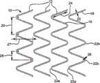
图2A是相邻支架元件之间具有柔性互连卷材的螺旋缠绕蛇形线支架的一部分的侧视图。2A is a side view of a portion of a helically wound serpentine wire stent with flexible interconnecting webs between adjacent stent elements.
图2B是图2A所示支架的展平的俯视图。Figure 2B is a flattened top view of the stent shown in Figure 2A.
图2C和2D是俯视图,其中图2B所示的各个单一开口由多个孔代替,具体是图2C中是四个开口,图2D中是六个开口。2C and 2D are top views, wherein each single opening shown in FIG. 2B is replaced by a plurality of holes, specifically four openings in FIG. 2C and six openings in FIG. 2D .
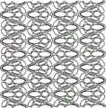
图3是用于制造所述开放框架支架的多轴ePTFE膜的扫描电镜图。Figure 3 is a scanning electron micrograph of the multiaxial ePTFE membrane used to fabricate the open frame scaffold.
图4描述了部分完成的具有缝隙或刺孔的支架的侧视图,所述缝隙或刺孔是制造所述装置的方法的一部分。Figure 4 depicts a side view of a partially completed stent with slits or punctures as part of the method of manufacturing the device.
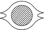
图5A-5C描述了支架元件的横截面图,该支架元件显示为用于根据本文所述制备的最终支架。5A-5C depict cross-sectional views of scaffold elements shown for use in final scaffolds prepared as described herein.
图6A是球囊扩张支架(或该支架的长度部分)的侧透视图,该支架的相邻支架元件之间具有柔性互连卷材。6A is a side perspective view of a balloon-expandable stent (or a length of the stent) having flexible interconnecting webs between adjacent stent elements.
图6B是三个支架环的侧透视图,所述支架如所示没有互连聚合物覆盖物。Figure 6B is a side perspective view of three rings of a stent shown without the interconnecting polymer covering.
图6C是包括图6B中所述支架环的支架组件的侧透视图,其具有互连聚合物覆盖物。6C is a side perspective view of a stent assembly including the stent rings described in FIG. 6B with an interconnected polymer cover.
图6D是图6C所述支架组件的上部左边部分,描述了透视细节部分。Figure 6D is an upper left portion of the bracket assembly of Figure 6C, illustrating perspective detail.
图7是球囊扩张支架(或该支架的长度部分)的侧透视图,该支架具有相邻支架元件之间的柔性互连卷材。Figure 7 is a side perspective view of a balloon expandable stent (or a length of the stent) having flexible interconnecting webs between adjacent stent elements.
图8是支架的侧视图,当该支架安装在随后展开和膨胀的球囊上时所显示的那样。Figure 8 is a side view of the stent as it is shown mounted on a subsequently deployed and inflated balloon.
具体实施方式Detailed ways
已经注意到,如本文所述,各种支架形式较好可具有柔性互连元件。图1A描述了支架10的透视图,该支架10较好如本文所述使用。所示支架10包括一定长度蛇形线18的螺旋线圈。所述螺旋缠绕蛇形线18的连续线圈产生了间隔的相邻支架元件12。线18的末端17可通过任何合适的方法(例如焊接)固定到相邻的螺旋线圈上。为清楚起见,所示支架10具有芯轴16延伸过并超出所述支架内腔的两个末端,使侧面最接近观察者,从而使之明显可见,同时封闭支架10离观察者最远侧。芯轴16仅仅是为了进行清楚地观察,并不是支架10的一部分。It has been noted that, as described herein, various stent forms may preferably have flexible interconnecting elements. Figure 1A depicts a perspective view of a
所述螺旋缠绕蛇形线18在支架10的相对末端之间连续延伸,其中由较小半径的线弯曲形成的相对顶点(apices)22a和22b通过笔直或较直的线部分24互连。所述顶点通常“指向”基本上平行于芯轴16的纵轴19的方向,且支架10的管状形式具有指向相对方向的交替的顶点22a和22b,即指向所述支架的相对末端。如图1A所示,指向一个方向的顶点(例如顶点22a)优选沿第一公用线对准,同时指向相对方向的顶点(例如顶点22b)沿平行第一公用线的第二公用线对准。The helically wound
图1B描述了图1A所示蛇形线形式的细节的平面(或平展)图;尺寸相对于下述的制造方法。尺寸27认为是相邻的相对顶点的高度(振幅(amplitude)),而尺寸28是相邻的相对顶点的宽度。尺寸29描述了蛇形线形式的一个全周期。顶点22的弯曲半径26和线直径25可适当选择。Figure IB depicts a plan (or flat) view of a detail of the serpentine form shown in Figure IA; the dimensions are relative to the fabrication method described below.
图2A是开口框架支架10的一部分长度的侧透视图,其中间隔的相邻支架元件12(例如两个相邻顶点22a链接相对的顶点22b)可通过一对柔性聚合物卷材32互连。图2B描述了该相同构造的平展的平面图。开口34存在于相邻对准的顶点22a之间;特定的单个开口18的形状通常是吉他拨片(guitar pick)形状。如果画一条通过独立的随机选择的卷材(即在相邻的且由卷材连接的线顶点之间延伸)的长度中心的线,该线优选相对平行于支架中心线(或平行于图1所示芯轴16的中心线19)的线成15-75度角。或者说,对于这类具有通过柔性卷材32互连的元件的支架而言,所述卷材32优选以相对于支架长度成一定角度取向。2A is a side perspective view of a portion of the length of an
图2B的放大部分描述了这些柔性聚合物卷材32如何在它们长度的中间部分窄于末端,所述聚合物卷材32在其末端附着在支架元件(例如镍钛合金线)上。它也描述了所述卷材32如何较好成切线地融入所述支架元件,所述卷材32在该融入位置粘结并附着在所述支架元件上。The enlarged portion of Figure 2B depicts how these flexible
图2C和2D是俯视图,其中图2B所示的每个单个开口被多个孔代替,具体地说,图2C中是四个开口,图2D中是六个开口。Figures 2C and 2D are top views in which each single opening shown in Figure 2B is replaced by a plurality of holes, specifically four openings in Figure 2C and six openings in Figure 2D.
尽管各种聚合物膜可适用作用于该装置的支架覆盖物(或涂层)材料,优选是与ePTFE膜组合使用的FEP(氟化乙丙烯)膜的组合。与这些螺旋缠绕蛇形线支架一起使用的优选ePTFE膜是具有多轴原纤取向(如图3的扫描电镜所示)的膜。它描述了所述原纤如何在ePTFE膜的平面内在所有方向上取向。这种类型的ePTFE膜可根据美国专利7306729和授予巴西诺(Bacino)等人的美国公开申请2007/0012624所示进行制造。相同类型的膜可任选具有FEP薄层的部分覆盖物(具有穿过该FEP膜覆盖物的开口;即不连续覆盖物)。FEP涂覆的ePTFE膜(具有不连续(多孔)FEP覆盖物(涂层)或连续(非多孔)FEP覆盖物(涂层))可通常根据授予梅尔斯(Myers)等人的美国专利5735892所示进行制造。Although various polymeric membranes are suitable as stent covering (or coating) materials for the device, a combination of FEP (fluorinated ethylene propylene) membranes used in combination with ePTFE membranes is preferred. Preferred ePTFE membranes for use with these helically wound serpentine wire scaffolds are those with a multiaxial fibril orientation (as shown in the scanning electron microscope of FIG. 3 ). It describes how the fibrils are oriented in all directions within the plane of the ePTFE membrane. This type of ePTFE membrane can be fabricated as shown in US Patent 7306729 and US Published Application 2007/0012624 to Bacino et al. Membranes of the same type may optionally have a partial covering of a thin layer of FEP (with openings through the covering of the FEP film; ie a discontinuous covering). FEP-coated ePTFE membranes (with a discontinuous (porous) FEP covering (coating) or a continuous (non-porous) FEP covering (coating)) can generally be obtained according to U.S. Patent 5,735,892 to Myers et al. Manufactured as shown.
图4描述了部分完成的螺旋缠绕蛇形线支架13,其具有FEP膜的第一外(外腔)覆盖物和多轴ePTFE膜的其它覆盖物,其中穿过所述线的相邻顶点(apex)之间的膜制造纵向取向的缝隙41,所述线定位于相同的方向。向具有多个缝隙41的装置施加热量,使所述膜向着相邻线支架元件缩回,随后在完成的支架15(图2A)中形成开口。该方法具体参见下述。Figure 4 depicts a partially completed helically wound
如所述,尽管各种类型的膜可用于所述支架覆盖物,但是所述ePTFE膜是优选的,因为其具有多轴(在所述膜的平面内)强度取向。它是坚固的、薄的,且具有优良的生物相容性。当在形成缝隙后进行适当的加热时,所述膜以良好的均一性回缩(缩回),从而形成穿过所述聚合物支架覆盖物的开口和在相邻支架元件之间形成柔性聚合物互连卷材。As mentioned, although various types of membranes can be used for the stent covering, the ePTFE membrane is preferred because of its multiaxial (in the plane of the membrane) strength orientation. It is strong, thin, and has excellent biocompatibility. When properly heated after slit formation, the membrane retracts (shrinks) with good uniformity, forming openings through the polymeric stent covering and flexible polymeric formation between adjacent stent elements. IoT coils.
由该方法得到的柔性互连卷材32通常在其末端具有较宽的宽度(所述卷材在该末端连接所述线顶点),且在它们互连的顶点之间的长度中央具有较窄的宽度。另外,可存在膜的非常薄的残留边缘(36,图2B),所述膜向外延伸离开所述笔直部分24中的线18,所述笔直部分24连接相同螺旋线圈中的顶点(即顶点22a和22b)。图5A描述了具有该边缘的线的横截面图(在图2B的平面图中所示的5部分截取),其描述了所述边缘的一般外观,所述边缘位于施加到所述支架的外表面或内表面上的覆膜材料单层。图5B和5C描述了施加到所述支架元件的内表面和外表面上的覆盖物所显示的横截面图。The
制造柔性支架的优选方法如下述。得到直径约等于想要的支架的内径的不锈钢芯轴。该芯轴表面具有1”宽
在相邻的线顶点之间形成纵向缝隙41,如图4所示,它们指向相同的方向。这些缝隙可通过任意合适的方法形成,包括使用解剖刀刀片、喷水、激光等。一种合适的激光是本能公司(Coherent Inc.)生产的产品,型号:GEM-100A,CO2,CW(仅连续波),美国加利福尼亚州的圣克拉拉市。如果需要使得末端排保持完全被覆盖(即以覆膜支架形式)的话,支架每个末端处的最后一排顶点可不形成缝隙。然后,在缠绕的支架的全部长度上提供其它临时的Kapton带螺旋缠绕物;该带的末端可用机械夹或其它临时固定装置固定到所述芯轴的表面上,超出所述支架的每个末端。该层Kapton接着用ePTFE带(由具有原纤微结构的ePTFE膜制成,且原纤维主要平行于所述带的长度取向,且以小的螺旋角缠绕,使得所述取向主要围绕所述芯轴)的临时螺旋缠绕物紧紧缠绕。当适当加热时,该ePTFE带向下层材料提供环向压缩。
上述构造体接着放入设定在380℃的合适对流烘箱中放置11分钟,然后从烘箱中拿出,并冷却到大约室温。然后除去ePEFE膜和Kapton带的外层。接着从所述芯轴上仔细除去所得的涂覆支架和下层Kapton带。然后,使用合适的工具(例如小镊子或钳子)从所述支架上除去剩余Kapton带子层。突出所述支架末端的剩余膜边缘可接着用解剖刀刀片在接近所述支架线末端顶点的横向上仔细修整。The above construct was then placed in a suitable convection oven set at 380°C for 11 minutes before being removed from the oven and allowed to cool to approximately room temperature. The ePEFE membrane and the outer layer of the Kapton tape are then removed. The resulting coated stent and underlying Kapton tape were then carefully removed from the mandrel. The remaining Kapton tape layer is then removed from the scaffold using a suitable tool such as tweezers or pliers. The remaining membrane edge protruding from the end of the stent can then be carefully trimmed with a scalpel blade in the transverse direction near the apex of the end of the stent wire.
图6A描述了球囊扩张支架60的透视图,它描述了下述的用球囊进行径向膨胀(diametrical expansion),其优选如本文中所述使用。所示支架60包括环62,其中球囊扩张的支架元件形成多个菱形开口63d;支架60通常包括一个或多个这些环62。可使用本领域中已知的任何合适方法来构造这些单个环62,但是优选通过激光切割管来制造。为清楚起见,仅显示了最接近观察者的管状支架60的侧面。支架60具有聚合物覆盖物66,优选是柔性膜。覆盖物66如何通过卷材32互连多个环62形成支架60是明显的,所述卷材32横跨相邻环62的顶点22a和22b之间的距离。FIG. 6A depicts a perspective view of a balloon-
尽管各种聚合物膜可用作用于该装置的支架覆盖物(或涂层)材料,但是优选是与ePTFE膜组合使用的FEP(氟化乙丙烯)的组合。用于该装置的优选ePTFE膜是在一个方向上具有更高强度的单轴膜,且该方向主要与球囊膨胀之前的支架纵轴61对准。该类型的膜类似于美国专利5476589中所公开的那些。另一种优选选择是通过施加不连续FEP涂层来改进所述膜,类似于美国专利6159565所公开的那些。Although various polymeric membranes can be used as the stent covering (or coating) material for this device, a combination of FEP (fluorinated ethylene propylene) used in combination with an ePTFE membrane is preferred. The preferred ePTFE membrane for this device is a uniaxial membrane with higher strength in one direction, which is primarily aligned with the
图6B描述了在所述环62在球囊膨胀之前显现时支架环62的布置,其没有聚合物覆盖物66。切割未膨胀的支架环62以具有开口63,该开口63在膨胀时变成菱形开口63d(如图6A所示)。支架环62彼此相邻放置,且顶点22a和22b呈典型的顶点-顶点对准。显然,相邻环62之间的距离可根据需要变化。FIG. 6B depicts the arrangement of the
图6C描述了前述图6B中所示的支架环62,其加入了互连聚合物覆盖物66。显示卷材32(每个卷材都是聚合物覆盖物66的一部分)与环62互连相邻。图6D是图6C中所示支架60的上部左面端的放大细节示意图。FIG. 6C depicts the
如图6C和6D所示,刺孔或缝隙68沿着支架60的纵轴在聚合物覆盖物66中排列。图6B-6D描述了形成在支架环62的相邻支架元件之间的多个开口63和64。穿过聚合物覆盖物66的缝隙68的尺寸和大小通常对应于每个支架环62中开口63和64的多样性(multiplicity)。这些缝隙68可通过前述各种方法形成。可穿过所述聚合物覆盖物66形成缝隙68,所述聚合物覆盖物66覆盖在相对顶点22a和22b之间延伸的开口63(封闭在每个支架环62之间的开口)。从每个支架环62的长度中央开始延伸并完全延伸到每个支架环62的末端的另一种开口64(即在径向相邻的顶点22a和22a之间,同样地在径向相邻的顶点22b和22b之间)也具有穿过所述覆盖物聚合物材料66的缝隙。这些缝隙68在相邻环62之间纵向延伸,且延伸入相邻环62中的对应开口。这些缝隙一起形成独立的互连卷材32。缝隙68的宽度可根据需要变化;相信解剖刀刀片的宽度是足够的,尽管附图中描述的缝隙68的宽度对应于下面的支架开口63和64的宽度。As shown in FIGS. 6C and 6D , punctures or
如图6A所示,每个环62的顶点22a和22b可制造成相互指向,或者可以如图7所示相互偏离(即,如图7所示峰-谷对准,这与图1A-2D、图4和图6A中所示的峰-峰对准相反)。所述顶点通常“指向”基本上平行于管状支架60的纵轴61的方向。As shown in FIG. 6A, the
图8是支架60安装在球囊(没有显示)上以随后展开和膨胀所显示的侧视图。支架60优选在安装过程中轴向压缩,使得互连卷材32弯曲或起皱,从而缩短所述支架60。以该种形式安装支架60的优点是在球囊膨胀过程中支架62缩短,因为它们会变形(开口63变成菱形开口63d)。例如,这使得缩短小于10%并得到大于6倍的径向膨胀成为可能。如果它们优选不向外突出的话,弯曲卷材32可在相邻支架环62下缩拢。优选的球囊(balloon)是从其长度中央向其相对末端径向膨胀的球囊。或者,在支架60的末端的环62可由比更接近支架60长度中央的环62更厚的材料制成。这些可替代方式可在膨胀过程中向弯曲的卷材32施加张力,从而将它们拉紧,增加它们的长度,以及补偿环62的缩短,以维持支架60的长度。Figure 8 is a side view showing the
制造支架(例如图6A-7所示的支架)的优选方法如下述。标准菱形几何图形支架是激光加工的,且在激光技术公司(Laserage Tchnology Inc.,美国依利诺斯州沃基根市)由316LVM不锈钢管(4.19毫米直径×.38壁厚,购自诺曼诺贝尔公司(Norman Noble),美国俄亥俄州克利夫兰市)进行电抛光。对所述支架进行表面粗糙化步骤,以提供附着,且没有降低耐疲劳性。在FEP粉末涂覆之前进行支架的等离子体处理,以清洁所述金属表面和降低金属表面的接触角。根据本领域中已知的常规方法进行等离子体处理。A preferred method of fabricating a stent, such as the stent shown in Figures 6A-7, is as follows. Standard diamond geometry stents were laser machined and made at Laserage Tchnology Inc. (Waukegan, IL, USA) from 316 LVM stainless steel tubing (4.19 mm diameter x .38 wall thickness, purchased from Norman Bell Corporation (Norman Noble, Cleveland, Ohio, USA) for electropolishing. A surface roughening step is performed on the stent to provide attachment without reducing fatigue resistance. Plasma treatment of the stent was performed prior to FEP powder coating to clean the metal surface and reduce the contact angle of the metal surface. Plasma treatment is performed according to conventional methods known in the art.
通过首先用标准厨房型混合器将所述粉末搅拌成空降(airborne)“云”并将所述框架悬浮在所述云中直到均匀的粉末层附着到所述支架框架上来将FEP粉末(美国大金公司(Daikin America),纽约州的桔堡市(Orangeburg))施加到所述支架组件上。所述支架组件接着于320℃热处理约3分钟。这使得所述粉末熔融,并作为涂层附着在所述支架组件上。每个环第二次涂覆,同时在相对末端将其悬浮,并放入320℃的烘箱中3分钟,然后取出,并冷却到室温。FEP powder (U.S. Gold Company (Daikin America, Orangeburg, NY) was applied to the stent assembly. The scaffold assembly was then heat treated at 320° C. for about 3 minutes. This causes the powder to fuse and adhere to the stent component as a coating. Each ring was coated a second time while suspending it at the opposite end and placed in a 320°C oven for 3 minutes, then removed and allowed to cool to room temperature.
如前述,十七层ePTFE薄层具有不连续的FEP涂层,然后缠绕不锈钢芯轴(约3.43毫米)。施加所述膜,且其高强度取向平行于支架的纵轴,且FEP侧朝外。单个支架环放在所述膜管上,并对准。在这种情况下,支架环以顶点-顶点对准,并在每个环之间均匀隔开约2.5毫米的缝隙,以得到约40毫米的整体装置长度。另一个相同的十七层膜如前述施加,不同的是FEP侧向下取向,朝着所述支架的外直径。Seventeen thin ePTFE layers with discontinuous FEP coating were then wound around a stainless steel mandrel (approximately 3.43 mm) as previously described. The membrane was applied with its high strength orientation parallel to the longitudinal axis of the scaffold, with the FEP side facing outward. A single scaffold ring is placed on the membrane tube and aligned. In this case, the stent rings were aligned apex-apex and evenly spaced about 2.5 mm gap between each ring to give an overall device length of about 40 mm. Another seventeen-layer membrane of the same type was applied as before, except that the FEP side was oriented down, towards the outer diameter of the scaffold.
整个组合件用几层ePTFE细线(元件#S024T4,美国马里兰州埃尔克顿市(Elkton)的WL戈尔公司)缠绕,以向下层构造体施加压缩力。将组合件放入320℃烘箱(格力夫(Grieves)MT1000型,格力夫公司(Grieve Corporation),美国依利诺斯州的圆湖(Round Lake)市)约40分钟。取出所述支架组合件,并冷却到室温。接着,除去外部(over-wrap)缠绕物,形成缝隙,且除去过量材料。The entire assembly was wrapped with several layers of thin ePTFE wire (element #S024T4, WL Gore, Elkton, MD, USA) to apply compressive forces to the underlying construct. The assembly was placed in a 320°C oven (Grieves Model MT1000, Grieve Corporation, Round Lake, Illinois, USA) for about 40 minutes. The rack assembly was removed and allowed to cool to room temperature. Next, the over-wrap is removed, a gap is formed, and excess material is removed.
尽管已经描述和在本文中记载了本发明的具体实施方式,但是本发明并没有局限于这些描述和说明。显然,可以在下述权利要求书的范围对本发明作出改进和改变。While specific embodiments of the invention have been described and recorded herein, the invention is not limited to such descriptions and illustrations. Obviously, modifications and changes may be made to the invention within the scope of the following claims.
Claims (17)
Translated fromChinesePriority Applications (2)
| Application Number | Priority Date | Filing Date | Title |
|---|---|---|---|
| CN201410052012.9ACN103784223B (en) | 2008-01-11 | 2009-01-09 | Stents with adjacent elements connected by flexible webs |
| CN201410051625.0ACN103767805B (en) | 2008-01-11 | 2009-01-09 | Be there is the support of the adjacent elements being connected by flexible web |
Applications Claiming Priority (5)
| Application Number | Priority Date | Filing Date | Title |
|---|---|---|---|
| US2054408P | 2008-01-11 | 2008-01-11 | |
| US61/020,544 | 2008-01-11 | ||
| US12/350,921US8926688B2 (en) | 2008-01-11 | 2009-01-08 | Stent having adjacent elements connected by flexible webs |
| US12/350,921 | 2009-01-08 | ||
| PCT/US2009/000144WO2009089055A1 (en) | 2008-01-11 | 2009-01-09 | Stent having adjacent elements connected by flexible webs |
Related Child Applications (2)
| Application Number | Title | Priority Date | Filing Date |
|---|---|---|---|
| CN201410052012.9ADivisionCN103784223B (en) | 2008-01-11 | 2009-01-09 | Stents with adjacent elements connected by flexible webs |
| CN201410051625.0ADivisionCN103767805B (en) | 2008-01-11 | 2009-01-09 | Be there is the support of the adjacent elements being connected by flexible web |
Publications (2)
| Publication Number | Publication Date |
|---|---|
| CN101909545A CN101909545A (en) | 2010-12-08 |
| CN101909545Btrue CN101909545B (en) | 2014-03-12 |
Family
ID=40851361
Family Applications (3)
| Application Number | Title | Priority Date | Filing Date |
|---|---|---|---|
| CN201410052012.9AActiveCN103784223B (en) | 2008-01-11 | 2009-01-09 | Stents with adjacent elements connected by flexible webs |
| CN200980102566.2AActiveCN101909545B (en) | 2008-01-11 | 2009-01-09 | Stents with adjacent elements connected by flexible webs |
| CN201410051625.0AActiveCN103767805B (en) | 2008-01-11 | 2009-01-09 | Be there is the support of the adjacent elements being connected by flexible web |
Family Applications Before (1)
| Application Number | Title | Priority Date | Filing Date |
|---|---|---|---|
| CN201410052012.9AActiveCN103784223B (en) | 2008-01-11 | 2009-01-09 | Stents with adjacent elements connected by flexible webs |
Family Applications After (1)
| Application Number | Title | Priority Date | Filing Date |
|---|---|---|---|
| CN201410051625.0AActiveCN103767805B (en) | 2008-01-11 | 2009-01-09 | Be there is the support of the adjacent elements being connected by flexible web |
Country Status (8)
| Country | Link |
|---|---|
| US (5) | US8926688B2 (en) |
| EP (2) | EP3530234B1 (en) |
| JP (1) | JP5722631B2 (en) |
| CN (3) | CN103784223B (en) |
| AU (1) | AU2009204460B2 (en) |
| CA (3) | CA2883830C (en) |
| ES (1) | ES2738533T3 (en) |
| WO (1) | WO2009089055A1 (en) |
Families Citing this family (135)
| Publication number | Priority date | Publication date | Assignee | Title |
|---|---|---|---|---|
| US6949121B1 (en) | 2002-02-07 | 2005-09-27 | Sentient Engineering & Technology, Llc | Apparatus and methods for conduits and materials |
| US9060844B2 (en) | 2002-11-01 | 2015-06-23 | Valentx, Inc. | Apparatus and methods for treatment of morbid obesity |
| US8070743B2 (en) | 2002-11-01 | 2011-12-06 | Valentx, Inc. | Devices and methods for attaching an endolumenal gastrointestinal implant |
| CA2881760C (en) | 2005-11-10 | 2017-06-13 | Arshad Quadri | Balloon-expandable, self-expanding, vascular prosthesis connecting stent |
| US9622888B2 (en) | 2006-11-16 | 2017-04-18 | W. L. Gore & Associates, Inc. | Stent having flexibly connected adjacent stent elements |
| US8128677B2 (en) | 2007-12-12 | 2012-03-06 | Intact Vascular LLC | Device and method for tacking plaque to a blood vessel wall |
| US8926688B2 (en) | 2008-01-11 | 2015-01-06 | W. L. Gore & Assoc. Inc. | Stent having adjacent elements connected by flexible webs |
| US20090276040A1 (en) | 2008-05-01 | 2009-11-05 | Edwards Lifesciences Corporation | Device and method for replacing mitral valve |
| US20100305686A1 (en)* | 2008-05-15 | 2010-12-02 | Cragg Andrew H | Low-profile modular abdominal aortic aneurysm graft |
| KR101547200B1 (en)* | 2008-06-27 | 2015-09-04 | 가부시키가이샤 교토 이료 세케이 | Vascular stent |
| JP5286006B2 (en)* | 2008-09-17 | 2013-09-11 | 日本ゴア株式会社 | Waterproof sound hood |
| CN102292053A (en) | 2008-09-29 | 2011-12-21 | 卡迪尔克阀门技术公司 | Heart valve |
| WO2010040009A1 (en) | 2008-10-01 | 2010-04-08 | Cardiaq Valve Technologies, Inc. | Delivery system for vascular implant |
| CA2961053C (en) | 2009-04-15 | 2019-04-30 | Edwards Lifesciences Cardiaq Llc | Vascular implant and delivery system |
| NZ596179A (en) | 2009-04-29 | 2014-05-30 | Cleveland Clinic Foundation | Apparatus and method for replacing a diseased cardiac valve |
| US9730790B2 (en) | 2009-09-29 | 2017-08-15 | Edwards Lifesciences Cardiaq Llc | Replacement valve and method |
| US8652203B2 (en) | 2010-09-23 | 2014-02-18 | Cardiaq Valve Technologies, Inc. | Replacement heart valves, delivery devices and methods |
| EP2506799A4 (en) | 2009-12-01 | 2014-10-29 | Altura Medical Inc | Modular endograft devices and associated systems and methods |
| US8449599B2 (en) | 2009-12-04 | 2013-05-28 | Edwards Lifesciences Corporation | Prosthetic valve for replacing mitral valve |
| WO2011120050A1 (en)* | 2010-03-26 | 2011-09-29 | Thubrikar Aortic Valve, Inc. | Valve component, frame component and prosthetic valve device including the same for implantation in a body lumen |
| US8579964B2 (en) | 2010-05-05 | 2013-11-12 | Neovasc Inc. | Transcatheter mitral valve prosthesis |
| WO2011163275A2 (en) | 2010-06-21 | 2011-12-29 | Cardiaq Valve Technologies, Inc. | Replacement heart valve |
| US10034740B2 (en)* | 2010-06-28 | 2018-07-31 | Cook Medical Technologies Llc | Covered stent |
| WO2012040240A1 (en) | 2010-09-20 | 2012-03-29 | Altura Medical, Inc. | Stent graft delivery systems and associated methods |
| US20130226282A1 (en)* | 2010-10-29 | 2013-08-29 | Medisourceplus Co., Ltd. | Stent wires, and method for manufacturing such stent wires and stents |
| WO2012064473A1 (en)* | 2010-11-09 | 2012-05-18 | Med Institute, Inc. | Covered stent devices for use in treatment of fracture |
| US9839540B2 (en) | 2011-01-14 | 2017-12-12 | W. L. Gore & Associates, Inc. | Stent |
| US10166128B2 (en) | 2011-01-14 | 2019-01-01 | W. L. Gore & Associates. Inc. | Lattice |
| US9744033B2 (en) | 2011-04-01 | 2017-08-29 | W.L. Gore & Associates, Inc. | Elastomeric leaflet for prosthetic heart valves |
| US9028444B2 (en) | 2011-04-15 | 2015-05-12 | W. L. Gore & Associates, Inc. | Pivoting ring seal |
| US9308087B2 (en) | 2011-04-28 | 2016-04-12 | Neovasc Tiara Inc. | Sequentially deployed transcatheter mitral valve prosthesis |
| US9554897B2 (en) | 2011-04-28 | 2017-01-31 | Neovasc Tiara Inc. | Methods and apparatus for engaging a valve prosthesis with tissue |
| US9370647B2 (en) | 2011-07-14 | 2016-06-21 | W. L. Gore & Associates, Inc. | Expandable medical devices |
| US9554806B2 (en) | 2011-09-16 | 2017-01-31 | W. L. Gore & Associates, Inc. | Occlusive devices |
| US20130085564A1 (en)* | 2011-10-03 | 2013-04-04 | Abbott Cardiovascular Systems Inc. | Modified scaffolds for peripheral applications |
| US9510935B2 (en) | 2012-01-16 | 2016-12-06 | W. L. Gore & Associates, Inc. | Articles including expanded polytetrafluoroethylene membranes with serpentine fibrils and having a discontinuous fluoropolymer layer thereon |
| US9345573B2 (en) | 2012-05-30 | 2016-05-24 | Neovasc Tiara Inc. | Methods and apparatus for loading a prosthesis onto a delivery system |
| US9681975B2 (en) | 2012-05-31 | 2017-06-20 | Valentx, Inc. | Devices and methods for gastrointestinal bypass |
| US9050168B2 (en) | 2012-05-31 | 2015-06-09 | Valentx, Inc. | Devices and methods for gastrointestinal bypass |
| US20130324906A1 (en) | 2012-05-31 | 2013-12-05 | Valen Tx, Inc. | Devices and methods for gastrointestinal bypass |
| US9283072B2 (en) | 2012-07-25 | 2016-03-15 | W. L. Gore & Associates, Inc. | Everting transcatheter valve and methods |
| US10376360B2 (en) | 2012-07-27 | 2019-08-13 | W. L. Gore & Associates, Inc. | Multi-frame prosthetic valve apparatus and methods |
| CA2881535A1 (en) | 2012-08-10 | 2014-02-13 | Altura Medical, Inc. | Stent delivery systems and associated methods |
| US8834556B2 (en) | 2012-08-13 | 2014-09-16 | Abbott Cardiovascular Systems Inc. | Segmented scaffold designs |
| US9931193B2 (en) | 2012-11-13 | 2018-04-03 | W. L. Gore & Associates, Inc. | Elastic stent graft |
| US10966820B2 (en) | 2012-12-19 | 2021-04-06 | W. L. Gore & Associates, Inc. | Geometric control of bending character in prosthetic heart valve leaflets |
| US10321986B2 (en) | 2012-12-19 | 2019-06-18 | W. L. Gore & Associates, Inc. | Multi-frame prosthetic heart valve |
| US10279084B2 (en) | 2012-12-19 | 2019-05-07 | W. L. Gore & Associates, Inc. | Medical balloon devices and methods |
| US9144492B2 (en) | 2012-12-19 | 2015-09-29 | W. L. Gore & Associates, Inc. | Truncated leaflet for prosthetic heart valves, preformed valve |
| US9737398B2 (en) | 2012-12-19 | 2017-08-22 | W. L. Gore & Associates, Inc. | Prosthetic valves, frames and leaflets and methods thereof |
| US9101469B2 (en) | 2012-12-19 | 2015-08-11 | W. L. Gore & Associates, Inc. | Prosthetic heart valve with leaflet shelving |
| US9968443B2 (en) | 2012-12-19 | 2018-05-15 | W. L. Gore & Associates, Inc. | Vertical coaptation zone in a planar portion of prosthetic heart valve leaflet |
| US9439763B2 (en) | 2013-02-04 | 2016-09-13 | Edwards Lifesciences Corporation | Prosthetic valve for replacing mitral valve |
| WO2014134568A2 (en) | 2013-03-01 | 2014-09-04 | The Regents Of The University Of California | Apparatus and methods for bidirectional hyperelastic stent covers |
| US10583002B2 (en) | 2013-03-11 | 2020-03-10 | Neovasc Tiara Inc. | Prosthetic valve with anti-pivoting mechanism |
| US9757264B2 (en) | 2013-03-13 | 2017-09-12 | Valentx, Inc. | Devices and methods for gastrointestinal bypass |
| US20140277427A1 (en) | 2013-03-14 | 2014-09-18 | Cardiaq Valve Technologies, Inc. | Prosthesis for atraumatically grasping intralumenal tissue and methods of delivery |
| US9681951B2 (en) | 2013-03-14 | 2017-06-20 | Edwards Lifesciences Cardiaq Llc | Prosthesis with outer skirt and anchors |
| US9669194B2 (en)* | 2013-03-14 | 2017-06-06 | W. L. Gore & Associates, Inc. | Conformable balloon devices and methods |
| US9770352B2 (en) | 2013-03-14 | 2017-09-26 | W. L. Gore & Associates, Inc. | Inflatable balloon and cover |
| US9730791B2 (en) | 2013-03-14 | 2017-08-15 | Edwards Lifesciences Cardiaq Llc | Prosthesis for atraumatically grasping intralumenal tissue and methods of delivery |
| WO2014144809A1 (en) | 2013-03-15 | 2014-09-18 | Altura Medical, Inc. | Endograft device delivery systems and associated methods |
| US9572665B2 (en) | 2013-04-04 | 2017-02-21 | Neovasc Tiara Inc. | Methods and apparatus for delivering a prosthetic valve to a beating heart |
| US11911258B2 (en) | 2013-06-26 | 2024-02-27 | W. L. Gore & Associates, Inc. | Space filling devices |
| US10842918B2 (en) | 2013-12-05 | 2020-11-24 | W.L. Gore & Associates, Inc. | Length extensible implantable device and methods for making such devices |
| EP3107497B1 (en) | 2014-02-21 | 2020-07-22 | Edwards Lifesciences CardiAQ LLC | Delivery device for controlled deployment of a replacement valve |
| USD755384S1 (en) | 2014-03-05 | 2016-05-03 | Edwards Lifesciences Cardiaq Llc | Stent |
| US11839698B2 (en) | 2014-03-13 | 2023-12-12 | W. L. Gore & Associates, Inc. | Drug composition and coating |
| KR101602389B1 (en)* | 2014-05-13 | 2016-03-10 | 주식회사 엠아이텍 | Stent and making method thereof |
| EP4470506A3 (en) | 2014-05-19 | 2025-01-08 | Edwards Lifesciences CardiAQ LLC | Replacement mitral valve with annular flap |
| US9532870B2 (en) | 2014-06-06 | 2017-01-03 | Edwards Lifesciences Corporation | Prosthetic valve for replacing a mitral valve |
| EP3156011A4 (en)* | 2014-06-12 | 2018-02-14 | National Cerebral and Cardiovascular Center | Stent |
| US9895243B2 (en)* | 2014-07-17 | 2018-02-20 | W. L. Gore & Associates, Inc. | Stent having adjacent elements connected by narrow flexible webs |
| CN105012059B (en)* | 2014-08-19 | 2017-02-15 | 东莞天天向上医疗科技有限公司 | Biodegradable drug stent |
| US9827094B2 (en) | 2014-09-15 | 2017-11-28 | W. L. Gore & Associates, Inc. | Prosthetic heart valve with retention elements |
| KR20170066470A (en) | 2014-09-28 | 2017-06-14 | 카디오키네틱스 인크. | Apparatuses for treating cardiac dysfunction |
| CN104287870B (en)* | 2014-10-10 | 2017-03-29 | 先健科技(深圳)有限公司 | Intraluminal stent |
| US10299948B2 (en) | 2014-11-26 | 2019-05-28 | W. L. Gore & Associates, Inc. | Balloon expandable endoprosthesis |
| US10531951B2 (en) | 2014-11-26 | 2020-01-14 | Edwards Lifesciences Corporation | Transcatheter prosthetic heart valve and delivery system |
| US9433520B2 (en) | 2015-01-29 | 2016-09-06 | Intact Vascular, Inc. | Delivery device and method of delivery |
| US9375336B1 (en) | 2015-01-29 | 2016-06-28 | Intact Vascular, Inc. | Delivery device and method of delivery |
| WO2016141215A1 (en)* | 2015-03-03 | 2016-09-09 | Efemoral Medical Llc | Multi-element bioresorbable intravascular stent |
| WO2016153918A1 (en) | 2015-03-20 | 2016-09-29 | Cardiokinetix, Inc. | Systems and methods for delivering an implantable device |
| CN106137481B (en)* | 2015-03-25 | 2018-03-06 | 微创神通医疗科技(上海)有限公司 | A kind of intravascular stent |
| US10441416B2 (en) | 2015-04-21 | 2019-10-15 | Edwards Lifesciences Corporation | Percutaneous mitral valve replacement device |
| US10376363B2 (en) | 2015-04-30 | 2019-08-13 | Edwards Lifesciences Cardiaq Llc | Replacement mitral valve, delivery system for replacement mitral valve and methods of use |
| CA2986047C (en) | 2015-05-14 | 2020-11-10 | W. L. Gore & Associates, Inc. | Devices and methods for occlusion of an atrial appendage |
| CA2990872C (en) | 2015-06-22 | 2022-03-22 | Edwards Lifescience Cardiaq Llc | Actively controllable heart valve implant and methods of controlling same |
| US10092400B2 (en) | 2015-06-23 | 2018-10-09 | Edwards Lifesciences Cardiaq Llc | Systems and methods for anchoring and sealing a prosthetic heart valve |
| US10117744B2 (en) | 2015-08-26 | 2018-11-06 | Edwards Lifesciences Cardiaq Llc | Replacement heart valves and methods of delivery |
| US10575951B2 (en) | 2015-08-26 | 2020-03-03 | Edwards Lifesciences Cardiaq Llc | Delivery device and methods of use for transapical delivery of replacement mitral valve |
| US10350066B2 (en) | 2015-08-28 | 2019-07-16 | Edwards Lifesciences Cardiaq Llc | Steerable delivery system for replacement mitral valve and methods of use |
| US10314726B2 (en) | 2015-09-10 | 2019-06-11 | Boston Scientific Scimed, Inc. | Stent with coated struts |
| US10561766B2 (en) | 2015-09-15 | 2020-02-18 | W. L. Gore & Associates, Inc. | Drug composition and coating |
| US10993824B2 (en) | 2016-01-01 | 2021-05-04 | Intact Vascular, Inc. | Delivery device and method of delivery |
| CN110742709B (en)* | 2016-03-18 | 2022-06-28 | 复旦大学附属中山医院 | A kind of aortic bare stent and aortic dissection stent |
| CN107303209B (en)* | 2016-04-17 | 2019-05-24 | 郭红 | With circumference to slot can be with curved tubular intravascular stent |
| EP4233806A3 (en) | 2016-04-21 | 2023-09-06 | W. L. Gore & Associates, Inc. | Diametrically adjustable endoprostheses |
| US10517711B2 (en)* | 2016-04-25 | 2019-12-31 | Medtronic Vascular, Inc. | Dissection prosthesis system and method |
| USD815744S1 (en) | 2016-04-28 | 2018-04-17 | Edwards Lifesciences Cardiaq Llc | Valve frame for a delivery system |
| US10568752B2 (en)* | 2016-05-25 | 2020-02-25 | W. L. Gore & Associates, Inc. | Controlled endoprosthesis balloon expansion |
| US10350062B2 (en) | 2016-07-21 | 2019-07-16 | Edwards Lifesciences Corporation | Replacement heart valve prosthesis |
| US10646340B2 (en) | 2016-08-19 | 2020-05-12 | Edwards Lifesciences Corporation | Steerable delivery system for replacement mitral valve |
| WO2018039631A1 (en) | 2016-08-26 | 2018-03-01 | Edwards Lifesciences Corporation | Multi-portion replacement heat valve prosthesis |
| US10758348B2 (en) | 2016-11-02 | 2020-09-01 | Edwards Lifesciences Corporation | Supra and sub-annular mitral valve delivery system |
| EP4112009A1 (en) | 2017-07-06 | 2023-01-04 | Edwards Lifesciences Corporation | Steerable rail delivery system |
| US11660218B2 (en) | 2017-07-26 | 2023-05-30 | Intact Vascular, Inc. | Delivery device and method of delivery |
| WO2019055577A1 (en) | 2017-09-12 | 2019-03-21 | W. L. Gore & Associates, Inc. | Leaflet frame attachment for prosthetic valves |
| US10786258B2 (en) | 2017-09-21 | 2020-09-29 | W. L. Gore & Associates, Inc. | Multiple inflation endovascular medical device |
| US10595874B2 (en) | 2017-09-21 | 2020-03-24 | W. L. Gore & Associates, Inc. | Multiple inflation endovascular medical device |
| CN111163728B (en) | 2017-09-27 | 2022-04-29 | W.L.戈尔及同仁股份有限公司 | Prosthetic valve with mechanically coupled leaflets |
| CN111132636B (en) | 2017-09-27 | 2022-04-08 | W.L.戈尔及同仁股份有限公司 | Prosthetic valve with expandable frame and related systems and methods |
| CN111194190A (en) | 2017-10-09 | 2020-05-22 | W.L.戈尔及同仁股份有限公司 | Matched support covering piece |
| US11090153B2 (en) | 2017-10-13 | 2021-08-17 | W. L. Gore & Associates, Inc. | Telescoping prosthetic valve and delivery system |
| US11173023B2 (en) | 2017-10-16 | 2021-11-16 | W. L. Gore & Associates, Inc. | Medical devices and anchors therefor |
| JP7072062B2 (en) | 2017-10-31 | 2022-05-19 | ダブリュ.エル.ゴア アンド アソシエイツ,インコーポレイティド | Transcatheter placement system and related methods |
| CN111295158A (en) | 2017-10-31 | 2020-06-16 | W.L.戈尔及同仁股份有限公司 | Medical valve and valve leaflet for promoting tissue ingrowth |
| EP3703618A1 (en) | 2017-10-31 | 2020-09-09 | W. L. Gore & Associates, Inc. | Prosthetic heart valve |
| CN117481869A (en) | 2018-01-25 | 2024-02-02 | 爱德华兹生命科学公司 | Delivery system for assisting in recapture and repositioning of replacement valves after deployment |
| US11051934B2 (en) | 2018-02-28 | 2021-07-06 | Edwards Lifesciences Corporation | Prosthetic mitral valve with improved anchors and seal |
| JP7570320B2 (en)* | 2018-09-19 | 2024-10-21 | エヌエックスティー バイオメディカル,エルエルシー | Methods and techniques for forming connections and shunts between cavities and vessels in biological structures - Patents.com |
| CN109646148B (en)* | 2019-01-16 | 2025-08-22 | 上海市第六人民医院 | A vascular stent |
| US11497601B2 (en) | 2019-03-01 | 2022-11-15 | W. L. Gore & Associates, Inc. | Telescoping prosthetic valve with retention element |
| FI3941392T3 (en) | 2019-03-20 | 2025-07-28 | Inqb8 Medical Tech Llc | Aortic dissection implant |
| ES2982566T3 (en) | 2019-04-23 | 2024-10-16 | Edwards Lifesciences Corp | Motorized implant delivery system |
| EP4051168A1 (en) | 2019-10-29 | 2022-09-07 | Boston Scientific Scimed, Inc. | Stent including anti-migration capabilities |
| US11191634B2 (en) | 2019-11-07 | 2021-12-07 | Cook Medical Technologies Llc | Aortic stent graft with durable suture attachment sites |
| DE102019135502B4 (en)* | 2019-12-20 | 2022-07-14 | Acandis Gmbh | Medical set, medical system and covering device for the treatment of aneurysms |
| EP4093327A1 (en) | 2020-01-21 | 2022-11-30 | W.L. Gore & Associates, Inc. | Endoprostheses with interlocking stents having varying stiffness |
| JP2023550224A (en)* | 2020-11-23 | 2023-12-01 | エフェモラル メディカル インコーポレイテッド | Segmented balloon expandable stent system to preserve arterial lumen during bending |
| EP4247297A1 (en) | 2020-12-18 | 2023-09-27 | Edwards Lifesciences Corporation | Storage jar assembly for aprosthetic heart valve |
| US20230172731A1 (en)* | 2021-02-25 | 2023-06-08 | Polyrey Medical Tech.(Suzhou) Co., Ltd. | Peripheral vascular stent and prepartion method thereof and application thereof |
| CN114948364B (en)* | 2021-02-25 | 2025-07-15 | 普利瑞医疗科技(苏州)有限公司 | A peripheral vascular stent and preparation method thereof |
| JP2025512490A (en) | 2022-04-14 | 2025-04-17 | ダブリュ.エル.ゴア アンド アソシエイツ,インコーポレイティド | Chemicals |
| CN119855627A (en)* | 2022-09-07 | 2025-04-18 | 斯瑞克公司 | Catheter with hypotube connected by connecting member and manufacturing method thereof |
Citations (5)
| Publication number | Priority date | Publication date | Assignee | Title |
|---|---|---|---|---|
| EP0951877A2 (en)* | 1998-04-20 | 1999-10-27 | Cordis Corporation | A multi-laminate stent having superelastic articulated sections |
| WO2000045741A1 (en)* | 1999-02-02 | 2000-08-10 | Impra, Inc. | Partial encapsulation of stents |
| CN1430491A (en)* | 2000-05-22 | 2003-07-16 | (株)精诚医学 | Metal stent for insertion in coronary artery |
| CN2633246Y (en)* | 2003-07-29 | 2004-08-18 | 上海市徐汇区中心医院 | Medical net shape rack |
| WO2006124824A1 (en)* | 2005-05-13 | 2006-11-23 | Alveolus, Inc. | Drainage stent and associated method |
Family Cites Families (301)
| Publication number | Priority date | Publication date | Assignee | Title |
|---|---|---|---|---|
| SE445884B (en)* | 1982-04-30 | 1986-07-28 | Medinvent Sa | DEVICE FOR IMPLANTATION OF A RODFORM PROTECTION |
| US4503569A (en)* | 1983-03-03 | 1985-03-12 | Dotter Charles T | Transluminally placed expandable graft prosthesis |
| US4733665C2 (en) | 1985-11-07 | 2002-01-29 | Expandable Grafts Partnership | Expandable intraluminal graft and method and apparatus for implanting an expandable intraluminal graft |
| US5102417A (en)* | 1985-11-07 | 1992-04-07 | Expandable Grafts Partnership | Expandable intraluminal graft, and method and apparatus for implanting an expandable intraluminal graft |
| SE453258B (en) | 1986-04-21 | 1988-01-25 | Medinvent Sa | ELASTIC, SELF-EXPANDING PROTEST AND PROCEDURE FOR ITS MANUFACTURING |
| JPS63238872A (en) | 1987-03-25 | 1988-10-04 | テルモ株式会社 | Instrument for securing inner diameter of cavity of tubular organ and catheter equipped therewith |
| US4884573A (en) | 1988-03-07 | 1989-12-05 | Leocor, Inc. | Very low profile angioplasty balloon catheter with capacity to use steerable, removable guidewire |
| US5019090A (en)* | 1988-09-01 | 1991-05-28 | Corvita Corporation | Radially expandable endoprosthesis and the like |
| US5300500A (en) | 1989-02-23 | 1994-04-05 | The University Of North Carolina At Chapel Hill | 4 beta-amino podophyllotoxin analog compounds and methods |
| IE73670B1 (en)* | 1989-10-02 | 1997-07-02 | Medtronic Inc | Articulated stent |
| US5290306A (en) | 1989-11-29 | 1994-03-01 | Cordis Corporation | Puncture resistant balloon catheter |
| US5123917A (en)* | 1990-04-27 | 1992-06-23 | Lee Peter Y | Expandable intraluminal vascular graft |
| US5360443A (en) | 1990-06-11 | 1994-11-01 | Barone Hector D | Aortic graft for repairing an abdominal aortic aneurysm |
| US5236447A (en) | 1990-06-29 | 1993-08-17 | Nissho Corporation | Artificial tubular organ |
| US5122154A (en)* | 1990-08-15 | 1992-06-16 | Rhodes Valentine J | Endovascular bypass graft |
| DE9117152U1 (en)* | 1990-10-09 | 1996-07-11 | Cook Inc., Bloomington, Ind. | Stent |
| US5330500A (en)* | 1990-10-18 | 1994-07-19 | Song Ho Y | Self-expanding endovascular stent with silicone coating |
| US5314472A (en)* | 1991-10-01 | 1994-05-24 | Cook Incorporated | Vascular stent |
| US6107004A (en) | 1991-09-05 | 2000-08-22 | Intra Therapeutics, Inc. | Method for making a tubular stent for use in medical applications |
| CA2079417C (en) | 1991-10-28 | 2003-01-07 | Lilip Lau | Expandable stents and method of making same |
| US5507767A (en)* | 1992-01-15 | 1996-04-16 | Cook Incorporated | Spiral stent |
| US5405377A (en)* | 1992-02-21 | 1995-04-11 | Endotech Ltd. | Intraluminal stent |
| US5683448A (en)* | 1992-02-21 | 1997-11-04 | Boston Scientific Technology, Inc. | Intraluminal stent and graft |
| US5282823A (en)* | 1992-03-19 | 1994-02-01 | Medtronic, Inc. | Intravascular radially expandable stent |
| EP0633798B1 (en)* | 1992-03-31 | 2003-05-07 | Boston Scientific Corporation | Vascular filter |
| US5201757A (en)* | 1992-04-03 | 1993-04-13 | Schneider (Usa) Inc. | Medial region deployment of radially self-expanding stents |
| US5507771A (en)* | 1992-06-15 | 1996-04-16 | Cook Incorporated | Stent assembly |
| US5562725A (en) | 1992-09-14 | 1996-10-08 | Meadox Medicals Inc. | Radially self-expanding implantable intraluminal device |
| FI944263L (en) | 1993-01-14 | 1994-10-28 | Meadox Medicals Inc | Prosthesis |
| EG20321A (en)* | 1993-07-21 | 1998-10-31 | Otsuka Pharma Co Ltd | Medical material and process for producing the same |
| US6159565A (en) | 1993-08-18 | 2000-12-12 | W. L. Gore & Associates, Inc. | Thin-wall intraluminal graft |
| US5735892A (en)* | 1993-08-18 | 1998-04-07 | W. L. Gore & Associates, Inc. | Intraluminal stent graft |
| US5409495A (en) | 1993-08-24 | 1995-04-25 | Advanced Cardiovascular Systems, Inc. | Apparatus for uniformly implanting a stent |
| US5443495A (en) | 1993-09-17 | 1995-08-22 | Scimed Lifesystems Inc. | Polymerization angioplasty balloon implant device |
| ES2135520T3 (en)* | 1993-11-04 | 1999-11-01 | Bard Inc C R | NON-MIGRANT VASCULAR PROSTHESIS. |
| US5545132A (en) | 1993-12-21 | 1996-08-13 | C. R. Bard, Inc. | Helically grooved balloon for dilatation catheter and method of using |
| US5609627A (en) | 1994-02-09 | 1997-03-11 | Boston Scientific Technology, Inc. | Method for delivering a bifurcated endoluminal prosthesis |
| US5549663A (en) | 1994-03-09 | 1996-08-27 | Cordis Corporation | Endoprosthesis having graft member and exposed welded end junctions, method and procedure |
| US5449373A (en) | 1994-03-17 | 1995-09-12 | Medinol Ltd. | Articulated stent |
| US6165210A (en) | 1994-04-01 | 2000-12-26 | Gore Enterprise Holdings, Inc. | Self-expandable helical intravascular stent and stent-graft |
| CA2157575C (en) | 1994-04-01 | 2000-03-07 | Lilip Lau | Self-expandable stent and stent-graft and method of using them |
| DE69528216T2 (en)* | 1994-06-17 | 2003-04-17 | Terumo K.K., Tokio/Tokyo | Process for the production of a permanent stent |
| DE69530891T2 (en)* | 1994-06-27 | 2004-05-13 | Corvita Corp., Miami | Bistable luminal graft endoprostheses |
| US5575816A (en) | 1994-08-12 | 1996-11-19 | Meadox Medicals, Inc. | High strength and high density intraluminal wire stent |
| US6331188B1 (en) | 1994-08-31 | 2001-12-18 | Gore Enterprise Holdings, Inc. | Exterior supported self-expanding stent-graft |
| EP0777567B1 (en) | 1994-09-02 | 2001-08-22 | W.L. Gore & Associates, Inc. | Porous polytetrafluoroethylene compositions |
| US6015429A (en)* | 1994-09-08 | 2000-01-18 | Gore Enterprise Holdings, Inc. | Procedures for introducing stents and stent-grafts |
| US5800521A (en) | 1994-11-09 | 1998-09-01 | Endotex Interventional Systems, Inc. | Prosthetic graft and method for aneurysm repair |
| EP0790810B1 (en)* | 1994-11-09 | 2004-04-28 | Endotex Interventional Systems, Inc. | Kit of delivery catheter and graft for aneurysm repair |
| US5628755A (en) | 1995-02-20 | 1997-05-13 | Schneider (Europe) A.G. | Balloon catheter and stent delivery system |
| DE4446036C2 (en) | 1994-12-23 | 1999-06-02 | Ruesch Willy Ag | Placeholder for placement in a body tube |
| WO1996021404A1 (en) | 1995-01-14 | 1996-07-18 | Prograft, Medical, Inc. | Kink-resistant stent-graft |
| AU719980B2 (en) | 1995-02-22 | 2000-05-18 | Menlo Care, Inc. | Covered expanding mesh stent |
| US5476589A (en) | 1995-03-10 | 1995-12-19 | W. L. Gore & Associates, Inc. | Porpous PTFE film and a manufacturing method therefor |
| JP3507503B2 (en)* | 1995-03-10 | 2004-03-15 | インプラ・インコーポレーテッド | Sealable stent for body cavity, method for producing the same, and method for introducing the same into body cavity |
| DE69626108T2 (en) | 1995-04-14 | 2003-11-20 | Boston Scientific Ltd., St. Michael | STENTING DEVICE WITH ROLLING MEMBRANE |
| AU5246696A (en) | 1995-05-30 | 1996-12-12 | Ethicon Inc. | Single-walled balloon catheter with non-linear compliance characteristic |
| AU7513596A (en) | 1995-06-02 | 1996-12-18 | Navius Corporation | Dual balloon stent delivery catheter |
| US6602281B1 (en) | 1995-06-05 | 2003-08-05 | Avantec Vascular Corporation | Radially expansible vessel scaffold having beams and expansion joints |
| FR2737404B1 (en) | 1995-08-03 | 1997-09-19 | Braun Celsa Sa | PROSTHESIS IMPLANTABLE IN A HUMAN OR ANIMAL CONDUCT, SUCH AS A WALL Expander, OR ANEURISM PROSTHESIS |
| WO1997009006A1 (en)* | 1995-09-01 | 1997-03-13 | Emory University | Endovascular support device and method of use |
| US20060271091A1 (en) | 1995-09-18 | 2006-11-30 | Campbell Carey V | Balloon catheter device |
| US5868704A (en) | 1995-09-18 | 1999-02-09 | W. L. Gore & Associates, Inc. | Balloon catheter device |
| US5824037A (en)* | 1995-10-03 | 1998-10-20 | Medtronic, Inc. | Modular intraluminal prostheses construction and methods |
| US6689162B1 (en)* | 1995-10-11 | 2004-02-10 | Boston Scientific Scimed, Inc. | Braided composite prosthesis |
| DE69636829T3 (en) | 1995-10-11 | 2016-07-21 | Terumo K.K. | Balloon for catheters and balloon catheters |
| US5591195A (en)* | 1995-10-30 | 1997-01-07 | Taheri; Syde | Apparatus and method for engrafting a blood vessel |
| ATE218052T1 (en) | 1995-11-27 | 2002-06-15 | Schneider Europ Gmbh | STENT FOR USE IN A PHYSICAL PASSAGE |
| US6579305B1 (en) | 1995-12-07 | 2003-06-17 | Medtronic Ave, Inc. | Method and apparatus for delivery deployment and retrieval of a stent comprising shape-memory material |
| ATE372745T1 (en)* | 1995-12-14 | 2007-09-15 | Gore Enterprise Holdings Inc | Kink-resistant Stent Graft |
| US6042605A (en)* | 1995-12-14 | 2000-03-28 | Gore Enterprose Holdings, Inc. | Kink resistant stent-graft |
| US5800512A (en) | 1996-01-22 | 1998-09-01 | Meadox Medicals, Inc. | PTFE vascular graft |
| US6016846A (en)* | 1996-02-07 | 2000-01-25 | Morgan Adhesives Company | Pipe insulation sleeve |
| CA2199890C (en) | 1996-03-26 | 2002-02-05 | Leonard Pinchuk | Stents and stent-grafts having enhanced hoop strength and methods of making the same |
| US5843161A (en) | 1996-06-26 | 1998-12-01 | Cordis Corporation | Endoprosthesis assembly for percutaneous deployment and method of deploying same |
| US5769884A (en) | 1996-06-27 | 1998-06-23 | Cordis Corporation | Controlled porosity endovascular implant |
| US5928279A (en)* | 1996-07-03 | 1999-07-27 | Baxter International Inc. | Stented, radially expandable, tubular PTFE grafts |
| US5749852A (en) | 1996-07-23 | 1998-05-12 | Medtronic, Inc. | Sheath system for autoperfusion dilatation catheter balloon |
| US5728150A (en)* | 1996-07-29 | 1998-03-17 | Cardiovascular Dynamics, Inc. | Expandable microporous prosthesis |
| US5922020A (en)* | 1996-08-02 | 1999-07-13 | Localmed, Inc. | Tubular prosthesis having improved expansion and imaging characteristics |
| DE19633901A1 (en) | 1996-08-22 | 1998-02-26 | Thomas Prof Dr Med Ischinger | Vascular support in the form of a tube section-like support structure |
| US6123712A (en) | 1996-08-23 | 2000-09-26 | Scimed Life Systems, Inc. | Balloon catheter with stent securement means |
| US6254628B1 (en) | 1996-12-09 | 2001-07-03 | Micro Therapeutics, Inc. | Intracranial stent |
| US5954764A (en)* | 1996-09-20 | 1999-09-21 | Parodi; Juan Carlos | Device for concurrently placing an endovascular expander with an endovascular prosthesis |
| US6315791B1 (en) | 1996-12-03 | 2001-11-13 | Atrium Medical Corporation | Self-expanding prothesis |
| US6551350B1 (en) | 1996-12-23 | 2003-04-22 | Gore Enterprise Holdings, Inc. | Kink resistant bifurcated prosthesis |
| US5843166A (en) | 1997-01-17 | 1998-12-01 | Meadox Medicals, Inc. | Composite graft-stent having pockets for accomodating movement |
| US5957974A (en) | 1997-01-23 | 1999-09-28 | Schneider (Usa) Inc | Stent graft with braided polymeric sleeve |
| US5899934A (en)* | 1997-01-31 | 1999-05-04 | Medtronic, Inc | Dual stent |
| US7384411B1 (en) | 1997-02-19 | 2008-06-10 | Condado Medical Devices Corporation | Multi-purpose catheters, catheter systems, and radiation treatment |
| WO1998038947A1 (en) | 1997-03-05 | 1998-09-11 | Scimed Life Systems, Inc. | Conformal laminate stent device |
| US6152944A (en) | 1997-03-05 | 2000-11-28 | Scimed Life Systems, Inc. | Catheter with removable balloon protector and stent delivery system with removable stent protector |
| US6048360A (en)* | 1997-03-18 | 2000-04-11 | Endotex Interventional Systems, Inc. | Methods of making and using coiled sheet graft for single and bifurcated lumens |
| US6159219A (en) | 1997-05-16 | 2000-12-12 | Scimed Life Systems, Inc | Stent retrieval device |
| US5824059A (en) | 1997-08-05 | 1998-10-20 | Wijay; Bandula | Flexible stent |
| US5984957A (en) | 1997-08-12 | 1999-11-16 | Schneider (Usa) Inc | Radially expanded prostheses with axial diameter control |
| IT238354Y1 (en) | 1997-09-12 | 2000-10-16 | Invatec Srl | DILATATION CATHETER FOR THE INTRODUCTION OF EXPANDABLE STENT |
| US6022374A (en)* | 1997-12-16 | 2000-02-08 | Cardiovasc, Inc. | Expandable stent having radiopaque marker and method |
| US6626939B1 (en) | 1997-12-18 | 2003-09-30 | Boston Scientific Scimed, Inc. | Stent-graft with bioabsorbable structural support |
| US6296633B1 (en) | 1998-01-09 | 2001-10-02 | Schneider (Usa) Inc. | Medical device tubing assembly and method of making the same |
| DK174814B1 (en) | 1998-02-25 | 2003-12-01 | Cook William Europ | stent device |
| US6488701B1 (en) | 1998-03-31 | 2002-12-03 | Medtronic Ave, Inc. | Stent-graft assembly with thin-walled graft component and method of manufacture |
| US6015432A (en)* | 1998-02-25 | 2000-01-18 | Cordis Corporation | Wire reinforced vascular prosthesis |
| US6077296A (en) | 1998-03-04 | 2000-06-20 | Endologix, Inc. | Endoluminal vascular prosthesis |
| EP1065993B1 (en)* | 1998-03-05 | 2010-08-11 | Boston Scientific Limited | Intraluminal stent |
| US6558415B2 (en)* | 1998-03-27 | 2003-05-06 | Intratherapeutics, Inc. | Stent |
| JPH11299901A (en)* | 1998-04-16 | 1999-11-02 | Johnson & Johnson Medical Kk | Stent and method for manufacturing the same |
| US6497722B1 (en) | 1998-05-04 | 2002-12-24 | Jomed Gmbh | Methods and apparatus for in-vivo tailored stents indicated for use in tortuous anatomy |
| US6224627B1 (en) | 1998-06-15 | 2001-05-01 | Gore Enterprise Holdings, Inc. | Remotely removable covering and support |
| US6171334B1 (en)* | 1998-06-17 | 2001-01-09 | Advanced Cardiovascular Systems, Inc. | Expandable stent and method of use |
| US6217609B1 (en)* | 1998-06-30 | 2001-04-17 | Schneider (Usa) Inc | Implantable endoprosthesis with patterned terminated ends and methods for making same |
| US6461380B1 (en) | 1998-07-28 | 2002-10-08 | Advanced Cardiovascular Systems, Inc. | Stent configuration |
| US6159239A (en) | 1998-08-14 | 2000-12-12 | Prodesco, Inc. | Woven stent/graft structure |
| US6143022A (en) | 1998-08-24 | 2000-11-07 | Medtronic Ave, Inc. | Stent-graft assembly with dual configuration graft component and method of manufacture |
| US6071307A (en) | 1998-09-30 | 2000-06-06 | Baxter International Inc. | Endoluminal grafts having continuously curvilinear wireforms |
| US6464718B1 (en) | 1998-11-16 | 2002-10-15 | Cordis Corporation | Balloon catheter for stent delivery having microchannels and method |
| US20060122691A1 (en)* | 1998-12-03 | 2006-06-08 | Jacob Richter | Hybrid stent |
| US6340366B2 (en)* | 1998-12-08 | 2002-01-22 | Bandula Wijay | Stent with nested or overlapping rings |
| US6336937B1 (en)* | 1998-12-09 | 2002-01-08 | Gore Enterprise Holdings, Inc. | Multi-stage expandable stent-graft |
| US6022359A (en) | 1999-01-13 | 2000-02-08 | Frantzen; John J. | Stent delivery system featuring a flexible balloon |
| US6350277B1 (en)* | 1999-01-15 | 2002-02-26 | Scimed Life Systems, Inc. | Stents with temporary retaining bands |
| EP1073385A2 (en) | 1999-01-22 | 2001-02-07 | Gore Enterprise Holdings, Inc. | A biliary stent-graft |
| EP1148899B1 (en) | 1999-01-25 | 2006-04-05 | Atrium Medical Corporation | Expandable fluoropolymer device for delivery of therapeutic agents |
| US6558414B2 (en)* | 1999-02-02 | 2003-05-06 | Impra, Inc. | Partial encapsulation of stents using strips and bands |
| US6231597B1 (en)* | 1999-02-16 | 2001-05-15 | Mark E. Deem | Apparatus and methods for selectively stenting a portion of a vessel wall |
| JP2000238714A (en)* | 1999-02-18 | 2000-09-05 | Kotecs Co Ltd | Sealing tool |
| JP2002537064A (en) | 1999-02-26 | 2002-11-05 | アドバンスド、カーディオバスキュラー、システムズ、インコーポレーテッド | Stent with customized flexibility |
| US6287333B1 (en) | 1999-03-15 | 2001-09-11 | Angiodynamics, Inc. | Flexible stent |
| US6364903B2 (en)* | 1999-03-19 | 2002-04-02 | Meadox Medicals, Inc. | Polymer coated stent |
| US6139575A (en) | 1999-04-02 | 2000-10-31 | Medtronic, Inc. | Hybrid mechanical heart valve prosthesis |
| US6425855B2 (en) | 1999-04-06 | 2002-07-30 | Cordis Corporation | Method for making a multi-laminate stent having superelastic articulated sections |
| US6273911B1 (en)* | 1999-04-22 | 2001-08-14 | Advanced Cardiovascular Systems, Inc. | Variable strength stent |
| CA2369307C (en) | 1999-05-11 | 2009-04-07 | Kaneka Corporation | Balloon catheter |
| US6375676B1 (en)* | 1999-05-17 | 2002-04-23 | Advanced Cardiovascular Systems, Inc. | Self-expanding stent with enhanced delivery precision and stent delivery system |
| US6673103B1 (en)* | 1999-05-20 | 2004-01-06 | Scimed Life Systems, Inc. | Mesh and stent for increased flexibility |
| JP4299973B2 (en) | 1999-05-20 | 2009-07-22 | ボストン サイエンティフィック リミテッド | Stent delivery system with a shrink stabilizer |
| US6409754B1 (en)* | 1999-07-02 | 2002-06-25 | Scimed Life Systems, Inc. | Flexible segmented stent |
| US20010018609A1 (en) | 1999-08-11 | 2001-08-30 | Scott Smith | Seamless braided or spun stent cover |
| KR100341019B1 (en) | 1999-08-18 | 2002-06-20 | 신경민 | The flexible self- expandable stent foundation device |
| US6503556B2 (en)* | 2000-12-28 | 2003-01-07 | Advanced Cardiovascular Systems, Inc. | Methods of forming a coating for a prosthesis |
| WO2001021101A1 (en) | 1999-09-22 | 2001-03-29 | Andrei Vladimirovich Karev | Flexible expandable stent and method for manufacturing the same |
| US6334868B1 (en)* | 1999-10-08 | 2002-01-01 | Advanced Cardiovascular Systems, Inc. | Stent cover |
| US7300457B2 (en)* | 1999-11-19 | 2007-11-27 | Advanced Bio Prosthetic Surfaces, Ltd. | Self-supporting metallic implantable grafts, compliant implantable medical devices and methods of making same |
| US6270522B1 (en) | 1999-12-21 | 2001-08-07 | Advanced Cardiovascular Systems, Inc. | High pressure catheter balloon |
| US6338739B1 (en) | 1999-12-22 | 2002-01-15 | Ethicon, Inc. | Biodegradable stent |
| US6537311B1 (en)* | 1999-12-30 | 2003-03-25 | Advanced Cardiovascular Systems, Inc. | Stent designs for use in peripheral vessels |
| US6312458B1 (en)* | 2000-01-19 | 2001-11-06 | Scimed Life Systems, Inc. | Tubular structure/stent/stent securement member |
| SI1255506T1 (en) | 2000-02-18 | 2004-02-29 | E.V.R. Endovascular Researches S.A. | Endolumenal device for delivering and deploying an endolumenal expandable prosthesis |
| US7141062B1 (en) | 2000-03-01 | 2006-11-28 | Medinol, Ltd. | Longitudinally flexible stent |
| US6290722B1 (en) | 2000-03-13 | 2001-09-18 | Endovascular Technologies, Inc. | Tacky attachment method of covered materials on stents |
| US6436132B1 (en) | 2000-03-30 | 2002-08-20 | Advanced Cardiovascular Systems, Inc. | Composite intraluminal prostheses |
| US6315708B1 (en)* | 2000-03-31 | 2001-11-13 | Cordis Corporation | Stent with self-expanding end sections |
| US6451050B1 (en) | 2000-04-28 | 2002-09-17 | Cardiovasc, Inc. | Stent graft and method |
| US6616689B1 (en) | 2000-05-03 | 2003-09-09 | Advanced Cardiovascular Systems, Inc. | Intravascular stent |
| US6283990B1 (en) | 2000-05-11 | 2001-09-04 | Nozomu Kanesaka | Combination of balloon and stent with specific sizes |
| US6554848B2 (en) | 2000-06-02 | 2003-04-29 | Advanced Cardiovascular Systems, Inc. | Marker device for rotationally orienting a stent delivery system prior to deploying a curved self-expanding stent |
| US6652579B1 (en) | 2000-06-22 | 2003-11-25 | Advanced Cardiovascular Systems, Inc. | Radiopaque stent |
| US6506202B1 (en) | 2000-07-10 | 2003-01-14 | Advanced Cardiovascular Systems, Inc. | Expandable stent dimensional retention system and method |
| JP2002035135A (en) | 2000-07-31 | 2002-02-05 | Manii Kk | Stent and method for manufacturing stent |
| US6629992B2 (en) | 2000-08-04 | 2003-10-07 | Advanced Cardiovascular Systems, Inc. | Sheath for self-expanding stent |
| US6511496B1 (en)* | 2000-09-12 | 2003-01-28 | Advanced Cardiovascular Systems, Inc. | Embolic protection device for use in interventional procedures |
| US7118592B1 (en) | 2000-09-12 | 2006-10-10 | Advanced Cardiovascular Systems, Inc. | Covered stent assembly for reduced-shortening during stent expansion |
| AU2002212621A1 (en) | 2000-09-14 | 2002-03-26 | Tuborg Engineering Nv | Adaptive balloon with improved flexibility |
| US6652574B1 (en) | 2000-09-28 | 2003-11-25 | Vascular Concepts Holdings Limited | Product and process for manufacturing a wire stent coated with a biocompatible fluoropolymer |
| US6620128B1 (en) | 2000-10-20 | 2003-09-16 | Advanced Cardiovascular Systems, Inc. | Balloon blowing process with metered volumetric inflation |
| US6945991B1 (en) | 2000-11-28 | 2005-09-20 | Boston Scientific/Scimed Life Systems, Inc. | Composite tubular prostheses |
| US7037318B2 (en) | 2000-12-18 | 2006-05-02 | Boston Scientific Scimed, Inc. | Catheter for controlled stent delivery |
| US20020084178A1 (en) | 2000-12-19 | 2002-07-04 | Nicast Corporation Ltd. | Method and apparatus for manufacturing polymer fiber shells via electrospinning |
| US20040030377A1 (en)* | 2001-10-19 | 2004-02-12 | Alexander Dubson | Medicated polymer-coated stent assembly |
| US7244272B2 (en)* | 2000-12-19 | 2007-07-17 | Nicast Ltd. | Vascular prosthesis and method for production thereof |
| US6565599B1 (en) | 2000-12-28 | 2003-05-20 | Advanced Cardiovascular Systems, Inc. | Hybrid stent |
| US6540776B2 (en)* | 2000-12-28 | 2003-04-01 | Advanced Cardiovascular Systems, Inc. | Sheath for a prosthesis and methods of forming the same |
| US6527739B1 (en) | 2000-12-29 | 2003-03-04 | Advanced Cardiovascular Systems, Inc. | Spiraled balloon arrangement for treatment of a tortuous vessel |
| US6899727B2 (en)* | 2001-01-22 | 2005-05-31 | Gore Enterprise Holdings, Inc. | Deployment system for intraluminal devices |
| US6942681B2 (en) | 2001-02-16 | 2005-09-13 | Cordis Corporation | Method of balloon catheter stent delivery system with ridges |
| US6740114B2 (en)* | 2001-03-01 | 2004-05-25 | Cordis Corporation | Flexible stent |
| US6872433B2 (en)* | 2001-03-27 | 2005-03-29 | The Regents Of The University Of California | Shape memory alloy/shape memory polymer tools |
| US6712357B1 (en)* | 2001-04-13 | 2004-03-30 | Unisys Corporation | Document pinch force control with soft pinch rollers and document pinch force control |
| US6551352B2 (en)* | 2001-05-03 | 2003-04-22 | Bionx Implants, Inc. | Method for attaching axial filaments to a self expanding stent |
| US20020165601A1 (en) | 2001-05-04 | 2002-11-07 | Clerc Claude O. | Bioabsorbable stent-graft and covered stent |
| US7510571B2 (en) | 2001-06-11 | 2009-03-31 | Boston Scientific, Scimed, Inc. | Pleated composite ePTFE/textile hybrid covering |
| US6585755B2 (en) | 2001-06-29 | 2003-07-01 | Advanced Cardiovascular | Polymeric stent suitable for imaging by MRI and fluoroscopy |
| US6540773B2 (en)* | 2001-07-03 | 2003-04-01 | Scimed Life Systems, Inc. | Low profile, high stretch knit prosthetic device |
| US6716239B2 (en)* | 2001-07-03 | 2004-04-06 | Scimed Life Systems, Inc. | ePTFE graft with axial elongation properties |
| US20030100945A1 (en)* | 2001-11-23 | 2003-05-29 | Mindguard Ltd. | Implantable intraluminal device and method of using same in treating aneurysms |
| US6605056B2 (en) | 2001-07-11 | 2003-08-12 | Scimed Life Systems, Inc. | Conformable balloon |
| AU2002320610A1 (en) | 2001-07-16 | 2003-03-03 | Altertek/Bio Inc | Tissue engineered heart valve |
| US6749584B2 (en) | 2001-08-17 | 2004-06-15 | Reva Medical, Inc. | Balloon protector sleeve |
| JP4377688B2 (en) | 2001-09-04 | 2009-12-02 | マイクロ セラピューティクス, インコーポレイテッド | Occlusion catheter with extensible balloon for use in complex vasculature |
| US6541589B1 (en) | 2001-10-15 | 2003-04-01 | Gore Enterprise Holdings, Inc. | Tetrafluoroethylene copolymer |
| US6991646B2 (en) | 2001-12-18 | 2006-01-31 | Linvatec Biomaterials, Inc. | Method and apparatus for delivering a stent into a body lumen |
| US6713357B1 (en) | 2001-12-20 | 2004-03-30 | Advanced Micro Devices, Inc. | Method to reduce parasitic capacitance of MOS transistors |
| US6866805B2 (en)* | 2001-12-27 | 2005-03-15 | Advanced Cardiovascular Systems, Inc. | Hybrid intravascular stent |
| US20030212449A1 (en) | 2001-12-28 | 2003-11-13 | Cox Daniel L. | Hybrid stent |
| US7163553B2 (en)* | 2001-12-28 | 2007-01-16 | Advanced Cardiovascular Systems, Inc. | Intravascular stent and method of use |
| JP3586245B2 (en)* | 2002-01-25 | 2004-11-10 | テルモ株式会社 | In-vivo stent |
| IL148616A (en)* | 2002-03-11 | 2008-03-20 | Oded Nahleili | Polymeric stent useful for the treatment of the salivary gland ducts |
| US7288111B1 (en) | 2002-03-26 | 2007-10-30 | Thoratec Corporation | Flexible stent and method of making the same |
| US7691461B1 (en)* | 2002-04-01 | 2010-04-06 | Advanced Cardiovascular Systems, Inc. | Hybrid stent and method of making |
| US7163533B2 (en)* | 2002-04-04 | 2007-01-16 | Angiodynamics, Inc. | Vascular treatment device and method |
| JP4170010B2 (en)* | 2002-04-08 | 2008-10-22 | テルモ株式会社 | Stent |
| US7105021B2 (en) | 2002-04-25 | 2006-09-12 | Scimed Life Systems, Inc. | Implantable textile prostheses having PTFE cold drawn yarns |
| US20030236563A1 (en) | 2002-06-20 | 2003-12-25 | Dan Fifer | Stent delivery catheter with retention bands |
| US7789908B2 (en)* | 2002-06-25 | 2010-09-07 | Boston Scientific Scimed, Inc. | Elastomerically impregnated ePTFE to enhance stretch and recovery properties for vascular grafts and coverings |
| US7556643B2 (en)* | 2002-07-24 | 2009-07-07 | Boston Scientific Scimed, Inc. | Graft inside stent |
| US20050154449A1 (en) | 2002-07-31 | 2005-07-14 | David Elmaleh | Non-biodegradable drug-eluting sleeves for intravascular devices |
| US20040024448A1 (en)* | 2002-08-05 | 2004-02-05 | Chang James W. | Thermoplastic fluoropolymer-coated medical devices |
| CA2495155A1 (en) | 2002-08-15 | 2004-02-26 | Gmp Cardiac Care, Inc. | Stent-graft with rails |
| CN1678366B (en)* | 2002-08-23 | 2010-06-09 | 国立循环器病中心总长所代表的日本国 | Stent and method of manufacturing the same |
| AU2003270817B2 (en)* | 2002-09-26 | 2009-09-17 | Vactronix Scientific, Llc | High strength vacuum deposited nitionol alloy films, medical thin film graft materials and method of making same |
| GB0223870D0 (en) | 2002-10-14 | 2002-11-20 | Cathnet Science Holding As | Stent assembly |
| US7144422B1 (en) | 2002-11-13 | 2006-12-05 | Advanced Cardiovascular Systems, Inc. | Drug-eluting stent and methods of making the same |
| US7141061B2 (en)* | 2002-11-14 | 2006-11-28 | Synecor, Llc | Photocurable endoprosthesis system |
| US20040172127A1 (en)* | 2002-12-09 | 2004-09-02 | John Kantor | Modular stent having polymer bridges at modular unit contact sites |
| DE10261822A1 (en)* | 2002-12-20 | 2004-07-01 | Biotronik Meß- und Therapiegeräte GmbH & Co. Ingenieurbüro Berlin | Helix bridge connection |
| US7455687B2 (en) | 2002-12-30 | 2008-11-25 | Advanced Cardiovascular Systems, Inc. | Polymer link hybrid stent |
| US7105018B1 (en)* | 2002-12-30 | 2006-09-12 | Advanced Cardiovascular Systems, Inc. | Drug-eluting stent cover and method of use |
| US7198636B2 (en) | 2003-01-17 | 2007-04-03 | Gore Enterprise Holdings, Inc. | Deployment system for an endoluminal device |
| US9333102B2 (en) | 2003-02-24 | 2016-05-10 | Allium Medical Solutions Ltd. | Stent |
| US7314480B2 (en) | 2003-02-27 | 2008-01-01 | Boston Scientific Scimed, Inc. | Rotating balloon expandable sheath bifurcation delivery |
| US7131981B2 (en) | 2003-03-25 | 2006-11-07 | Angiodynamics, Inc. | Device and method for converting a balloon catheter into a cutting balloon catheter |
| US20050209672A1 (en) | 2004-03-02 | 2005-09-22 | Cardiomind, Inc. | Sliding restraint stent delivery systems |
| US7731747B2 (en) | 2003-04-14 | 2010-06-08 | Tryton Medical, Inc. | Vascular bifurcation prosthesis with multiple thin fronds |
| US7972372B2 (en) | 2003-04-14 | 2011-07-05 | Tryton Medical, Inc. | Kit for treating vascular bifurcations |
| US20050004647A1 (en)* | 2003-07-03 | 2005-01-06 | William Cook Europe Aps | Hybrid stent apparatus |
| US20050065437A1 (en)* | 2003-09-24 | 2005-03-24 | Scimed Life Systems, Inc. | Medical device with markers for magnetic resonance visibility |
| AU2004289362A1 (en) | 2003-11-10 | 2005-05-26 | Angiotech International Ag | Intravascular devices and fibrosis-inducing agents |
| US7258697B1 (en) | 2003-12-22 | 2007-08-21 | Advanced Cardiovascular Systems, Inc. | Stent with anchors to prevent vulnerable plaque rupture during deployment |
| US7686841B2 (en) | 2003-12-29 | 2010-03-30 | Boston Scientific Scimed, Inc. | Rotating balloon expandable sheath bifurcation delivery system |
| US20050182474A1 (en) | 2004-02-13 | 2005-08-18 | Medtronic Vascular, Inc. | Coated stent having protruding crowns and elongated struts |
| US8377110B2 (en) | 2004-04-08 | 2013-02-19 | Endologix, Inc. | Endolumenal vascular prosthesis with neointima inhibiting polymeric sleeve |
| US7727271B2 (en)* | 2004-06-24 | 2010-06-01 | Boston Scientific Scimed, Inc. | Implantable prosthesis having reinforced attachment sites |
| AU2005269864B2 (en)* | 2004-07-07 | 2011-01-06 | Cook Medical Technologies Llc | Graft, stent graft and method for manufacture |
| US7323008B2 (en)* | 2004-08-09 | 2008-01-29 | Medtronic Vascular, Inc. | Flexible stent |
| US20060036308A1 (en)* | 2004-08-12 | 2006-02-16 | Medtronic Vascular, Inc. | Stent with extruded covering |
| US20060058867A1 (en)* | 2004-09-15 | 2006-03-16 | Thistle Robert C | Elastomeric radiopaque adhesive composite and prosthesis |
| DE102004045224B4 (en)* | 2004-09-17 | 2010-12-30 | Thilo Dr. Fliedner | support prosthesis |
| US20060085065A1 (en)* | 2004-10-15 | 2006-04-20 | Krause Arthur A | Stent with auxiliary treatment structure |
| JP2006175017A (en)* | 2004-12-22 | 2006-07-06 | Homuzu Giken:Kk | Manufacturing method of stent and stent |
| US20060190072A1 (en) | 2005-01-28 | 2006-08-24 | Das Gladwin S | Flexible cells for axially interconnecting stent components |
| US7491225B2 (en) | 2005-02-16 | 2009-02-17 | Boston Scientific Scimed, Inc. | System and method for deploying a drug-eluting external body and tissue scaffold |
| US20070055365A1 (en)* | 2005-04-28 | 2007-03-08 | The Cleveland Clinic Foundation | Stent with integrated filter |
| CA2609687C (en) | 2005-05-24 | 2014-04-22 | Inspire M.D Ltd. | Stent apparatuses for treatment via body lumens and methods of use |
| US8672990B2 (en) | 2005-05-27 | 2014-03-18 | Boston Scientific Scimed, Inc. | Fiber mesh controlled expansion balloon catheter |
| US7967836B2 (en) | 2005-06-17 | 2011-06-28 | Abbott Laboratories | Dilatation balloon having reduced rigidity |
| WO2007002423A2 (en) | 2005-06-24 | 2007-01-04 | Abbott Laboratories | Balloon catheter |
| US7306729B2 (en) | 2005-07-18 | 2007-12-11 | Gore Enterprise Holdings, Inc. | Porous PTFE materials and articles produced therefrom |
| US20070129791A1 (en)* | 2005-12-05 | 2007-06-07 | Balaji Malur R | Stent with integral filter |
| US20080161901A1 (en) | 2006-01-25 | 2008-07-03 | Heuser Richard R | Catheter system with stent apparatus for connecting adjacent blood vessels |
| US8597341B2 (en) | 2006-03-06 | 2013-12-03 | David Elmaleh | Intravascular device with netting system |
| US8425584B2 (en)* | 2006-04-21 | 2013-04-23 | W. L. Gore & Associates, Inc. | Expandable covered stent with wide range of wrinkle-free deployed diameters |
| US8721704B2 (en)* | 2006-04-21 | 2014-05-13 | W. L. Gore & Associates, Inc. | Expandable stent with wrinkle-free elastomeric cover |
| US7785290B2 (en) | 2006-08-07 | 2010-08-31 | Gore Enterprise Holdings, Inc. | Non-shortening high angle wrapped balloons |
| US8979886B2 (en) | 2006-08-07 | 2015-03-17 | W. L. Gore & Associates, Inc. | Medical balloon and method of making the same |
| US20080140173A1 (en) | 2006-08-07 | 2008-06-12 | Sherif Eskaros | Non-shortening wrapped balloon |
| US9622888B2 (en) | 2006-11-16 | 2017-04-18 | W. L. Gore & Associates, Inc. | Stent having flexibly connected adjacent stent elements |
| CA2677596C (en)* | 2007-03-23 | 2014-12-16 | Invatec Technology Center Gmbh | Endoluminal prosthesis |
| US20080319388A1 (en) | 2007-06-21 | 2008-12-25 | David Slattery | Device delivery system with balloon-relative sheath positioning |
| US20090018635A1 (en) | 2007-07-10 | 2009-01-15 | Boston Scientific Scimed, Inc. | Stent protector |
| US20090069878A1 (en) | 2007-08-27 | 2009-03-12 | Boston Scientific Scimed, Inc. | Bifurcation post-dilatation balloon and methods |
| US8142490B2 (en)* | 2007-10-24 | 2012-03-27 | Cordis Corporation | Stent segments axially connected by thin film |
| US8858863B2 (en) | 2007-11-21 | 2014-10-14 | Invatec S.P.A. | Balloon for the treatment of stenosis and method for manufacturing the balloon |
| US8926688B2 (en) | 2008-01-11 | 2015-01-06 | W. L. Gore & Assoc. Inc. | Stent having adjacent elements connected by flexible webs |
| DE102008006092A1 (en) | 2008-01-25 | 2009-07-30 | Biotronik Vi Patent Ag | Multiple membrane balloon and method of making a multiple membrane balloon |
| US20090234429A1 (en) | 2008-02-07 | 2009-09-17 | Lilip Lau | Self-restraining endoluminal prosthesis |
| CN102292053A (en) | 2008-09-29 | 2011-12-21 | 卡迪尔克阀门技术公司 | Heart valve |
| CN101822868A (en) | 2009-03-03 | 2010-09-08 | 孙波 | Medical stent type supporting balloon and water injection type covered stent |
| US20100228333A1 (en) | 2009-03-04 | 2010-09-09 | William Joseph Drasler | Drug eluting surface covering |
| US8221489B2 (en) | 2009-08-20 | 2012-07-17 | Stentys | Device and method for treating a body lumen |
| US20110087191A1 (en) | 2009-10-14 | 2011-04-14 | Boston Scientific Scimed, Inc. | Balloon catheter with shape memory sheath for delivery of therapeutic agent |
| JP2011206124A (en) | 2010-03-29 | 2011-10-20 | Terumo Corp | Balloon catheter |
| AU2010201676B1 (en) | 2010-04-23 | 2010-07-22 | Cook Medical Technologies Llc | Curve forming stent graft |
| US10780251B2 (en) | 2010-09-17 | 2020-09-22 | W. L. Gore & Associates, Inc. | Expandable medical devices |
| GB201018869D0 (en) | 2010-11-08 | 2010-12-22 | Isis Innovation | Curved stent graft assembly |
| US9895517B2 (en) | 2011-01-18 | 2018-02-20 | Loma Vista Medical, Inc. | Inflatable medical devices |
| CN103561686B (en) | 2011-03-03 | 2016-03-30 | 英派尔科技开发有限公司 | Temporary perfusion channel for percutaneous delivery of expandable balloon stents |
| US9370643B2 (en) | 2011-06-23 | 2016-06-21 | W.L. Gore & Associates, Inc. | High strength balloon cover |
| US10016579B2 (en) | 2011-06-23 | 2018-07-10 | W.L. Gore & Associates, Inc. | Controllable inflation profile balloon cover apparatus |
| US9370647B2 (en) | 2011-07-14 | 2016-06-21 | W. L. Gore & Associates, Inc. | Expandable medical devices |
| US9730726B2 (en) | 2011-10-07 | 2017-08-15 | W. L. Gore & Associates, Inc. | Balloon assemblies having controllably variable topographies |
| JP6295204B2 (en) | 2011-12-23 | 2018-03-14 | アビオメド インコーポレイテッド | Heart valve prosthesis with an open stent |
| US9510935B2 (en) | 2012-01-16 | 2016-12-06 | W. L. Gore & Associates, Inc. | Articles including expanded polytetrafluoroethylene membranes with serpentine fibrils and having a discontinuous fluoropolymer layer thereon |
| US9700399B2 (en) | 2012-04-26 | 2017-07-11 | Medtronic Vascular, Inc. | Stopper to prevent graft material slippage in a closed web stent-graft |
| US9901715B2 (en) | 2012-09-05 | 2018-02-27 | W. L. Gore Associates, Inc. | Retractable sheath devices, systems, and methods |
| CN102940543A (en) | 2012-09-25 | 2013-02-27 | 苏州爱瑞德医疗科技有限公司 | Combined medical instrument formed by drug coated balloon and stent |
| US9724219B2 (en) | 2012-10-04 | 2017-08-08 | Abbott Cardiovascular Systems Inc. | Method of uniform crimping and expansion of medical devices |
| EP2730309A1 (en) | 2012-11-13 | 2014-05-14 | Biotronik AG | Balloon catheter for curved vessels |
| US9629735B2 (en) | 2012-11-16 | 2017-04-25 | W. L. Gore & Associates, Inc. | Flexible endoluminal device |
| US10279084B2 (en) | 2012-12-19 | 2019-05-07 | W. L. Gore & Associates, Inc. | Medical balloon devices and methods |
| US20140277331A1 (en) | 2013-03-13 | 2014-09-18 | Abbott Cardiovascular Systems Inc. | Reducing Recoil in Peripherally-Implanted Scaffolds |
| US9770352B2 (en) | 2013-03-14 | 2017-09-26 | W. L. Gore & Associates, Inc. | Inflatable balloon and cover |
| US9669194B2 (en) | 2013-03-14 | 2017-06-06 | W. L. Gore & Associates, Inc. | Conformable balloon devices and methods |
| US9522072B2 (en) | 2013-03-15 | 2016-12-20 | W. L. Gore & Associates, Inc. | Porous materials having a fibrillar microstructure and a fracturable coating |
| US9149612B2 (en) | 2013-11-13 | 2015-10-06 | West Coast Catheter, Inc. | Flexible high-pressure balloons |
| WO2015073114A1 (en) | 2013-11-13 | 2015-05-21 | West Coast Catheter, Inc. | Flexible high-pressure balloons |
| GB2525005B (en) | 2014-04-09 | 2016-03-09 | Cook Medical Technologies Llc | Delivery system for implantable medical device |
| US10299948B2 (en) | 2014-11-26 | 2019-05-28 | W. L. Gore & Associates, Inc. | Balloon expandable endoprosthesis |
| US10470905B2 (en) | 2016-03-25 | 2019-11-12 | Ostial Corporation | Balloon catheters and methods for use |
| US10568752B2 (en) | 2016-05-25 | 2020-02-25 | W. L. Gore & Associates, Inc. | Controlled endoprosthesis balloon expansion |
| WO2018039444A1 (en) | 2016-08-25 | 2018-03-01 | Mico Innovations, Llc | Neurovascular stent |
| AU2019261353B2 (en) | 2018-04-24 | 2022-06-16 | W. L. Gore & Associates, Inc. | Balloon catheters, systems and methods |
- 2009
- 2009-01-08USUS12/350,921patent/US8926688B2/enactiveActive
- 2009-01-09JPJP2010542279Apatent/JP5722631B2/enactiveActive
- 2009-01-09EPEP19167993.5Apatent/EP3530234B1/enactiveActive
- 2009-01-09CNCN201410052012.9Apatent/CN103784223B/enactiveActive
- 2009-01-09CACA2883830Apatent/CA2883830C/enactiveActive
- 2009-01-09ESES09700293Tpatent/ES2738533T3/enactiveActive
- 2009-01-09CNCN200980102566.2Apatent/CN101909545B/enactiveActive
- 2009-01-09WOPCT/US2009/000144patent/WO2009089055A1/enactiveApplication Filing
- 2009-01-09CACA2816197Apatent/CA2816197C/enactiveActive
- 2009-01-09EPEP09700293.5Apatent/EP2249744B1/enactiveActive
- 2009-01-09AUAU2009204460Apatent/AU2009204460B2/enactiveActive
- 2009-01-09CACA2711831Apatent/CA2711831C/enactiveActive
- 2009-01-09CNCN201410051625.0Apatent/CN103767805B/enactiveActive
- 2012
- 2012-01-12USUS13/349,346patent/US9943428B2/enactiveActive
- 2018
- 2018-03-08USUS15/915,453patent/US11103372B2/enactiveActive
- 2021
- 2021-08-09USUS17/397,362patent/US11865020B2/enactiveActive
- 2023
- 2023-12-05USUS18/529,931patent/US12329667B2/enactiveActive
Patent Citations (5)
| Publication number | Priority date | Publication date | Assignee | Title |
|---|---|---|---|---|
| EP0951877A2 (en)* | 1998-04-20 | 1999-10-27 | Cordis Corporation | A multi-laminate stent having superelastic articulated sections |
| WO2000045741A1 (en)* | 1999-02-02 | 2000-08-10 | Impra, Inc. | Partial encapsulation of stents |
| CN1430491A (en)* | 2000-05-22 | 2003-07-16 | (株)精诚医学 | Metal stent for insertion in coronary artery |
| CN2633246Y (en)* | 2003-07-29 | 2004-08-18 | 上海市徐汇区中心医院 | Medical net shape rack |
| WO2006124824A1 (en)* | 2005-05-13 | 2006-11-23 | Alveolus, Inc. | Drainage stent and associated method |
Also Published As
| Publication number | Publication date |
|---|---|
| CA2816197C (en) | 2016-07-26 |
| CN103767805B (en) | 2016-09-14 |
| CN103784223A (en) | 2014-05-14 |
| US9943428B2 (en) | 2018-04-17 |
| US20210361451A1 (en) | 2021-11-25 |
| CA2711831A1 (en) | 2009-07-16 |
| CN101909545A (en) | 2010-12-08 |
| US20240173154A1 (en) | 2024-05-30 |
| CA2883830A1 (en) | 2009-07-16 |
| US20120109283A1 (en) | 2012-05-03 |
| CA2883830C (en) | 2017-07-25 |
| US20180193177A1 (en) | 2018-07-12 |
| ES2738533T3 (en) | 2020-01-23 |
| US12329667B2 (en) | 2025-06-17 |
| CA2711831C (en) | 2014-12-02 |
| AU2009204460A1 (en) | 2009-07-16 |
| CN103784223B (en) | 2019-08-09 |
| US20090182413A1 (en) | 2009-07-16 |
| EP2249744B1 (en) | 2019-05-15 |
| JP5722631B2 (en) | 2015-05-27 |
| CN103767805A (en) | 2014-05-07 |
| EP3530234A1 (en) | 2019-08-28 |
| US8926688B2 (en) | 2015-01-06 |
| CA2816197A1 (en) | 2009-07-16 |
| AU2009204460B2 (en) | 2013-02-07 |
| JP2011509151A (en) | 2011-03-24 |
| US11103372B2 (en) | 2021-08-31 |
| EP3530234B1 (en) | 2025-08-20 |
| WO2009089055A1 (en) | 2009-07-16 |
| EP2249744A1 (en) | 2010-11-17 |
| US11865020B2 (en) | 2024-01-09 |
Similar Documents
| Publication | Publication Date | Title |
|---|---|---|
| CN101909545B (en) | Stents with adjacent elements connected by flexible webs | |
| US20240180728A1 (en) | Stent having adjacent elements connected by narrow flexible webs | |
| AU2015275263B2 (en) | Method of making a flexible stent | |
| AU2013205751B2 (en) | Stent having adjacent elements connected by flexible webs | |
| HK40011015A (en) | Stent having adjacent elements connected by flexible webs | |
| HK1145431B (en) | Stent having adjacent elements connected by flexible webs | |
| HK1145431A (en) | Stent having adjacent elements connected by flexible webs |
Legal Events
| Date | Code | Title | Description |
|---|---|---|---|
| C06 | Publication | ||
| PB01 | Publication | ||
| C10 | Entry into substantive examination | ||
| SE01 | Entry into force of request for substantive examination | ||
| GR01 | Patent grant | ||
| GR01 | Patent grant | ||
| C41 | Transfer of patent application or patent right or utility model | ||
| TR01 | Transfer of patent right | Effective date of registration:20150914 Address after:Delaware Patentee after:W. L. Gore & Associates, Inc. Address before:Delaware Patentee before:Gore Enterprise Holdings, Inc. |