CN101907450B - Construction method of three-dimensional macro morphology of combined surface containing materials with different reflectivities - Google Patents
Construction method of three-dimensional macro morphology of combined surface containing materials with different reflectivitiesDownload PDFInfo
- Publication number
- CN101907450B CN101907450BCN2010102331725ACN201010233172ACN101907450BCN 101907450 BCN101907450 BCN 101907450BCN 2010102331725 ACN2010102331725 ACN 2010102331725ACN 201010233172 ACN201010233172 ACN 201010233172ACN 101907450 BCN101907450 BCN 101907450B
- Authority
- CN
- China
- Prior art keywords
- dimensional
- image
- sub
- topography
- reflectance
- Prior art date
- Legal status (The legal status is an assumption and is not a legal conclusion. Google has not performed a legal analysis and makes no representation as to the accuracy of the status listed.)
- Expired - Fee Related
Links
Images


Landscapes
- Image Processing (AREA)
Abstract
Translated fromChinese
Description
Translated fromChinese技术领域 本发明属于物体表面观察与测量的科学技术领域,具体涉及一种不同反射率材质组合表面的三维宏观形貌构建方法。 Technical Field The present invention belongs to the scientific and technical field of object surface observation and measurement, and specifically relates to a method for constructing a three-dimensional macroscopic topography of a surface composed of materials with different reflectivity. the
背景技术 在许多科学技术的领域,人们依靠肉眼或低倍放大镜观测物体表面的形态及其质量,往往获得某个视角方向上片面和失真图像的视觉信息:或正视物体表面时真实看到一幅平面图像的二维尺寸,却丢失(聚缩)了该表面垂直方向的第三维深度信息;或斜视物体表面时失真看到轴测投影方向的立体图像,其视觉中的表面形状发生了变形,相机从这些视角方向纪录下的轴测图像都没有可度量性。因此,目前众多科学技术领域观察与检测物体表面形态及其质量的传统方法,普遍存在着以面代体或者变形失真地获取物体表面信息的片面性和主观性这一不足。 Background technology In many fields of science and technology, people rely on the naked eye or a low-power magnifying glass to observe the shape and quality of the surface of an object, and often obtain visual information of one-sided and distorted images in a certain viewing angle direction: or see a real image when looking squarely at the surface of an object. The two-dimensional size of the planar image loses (shrinks) the third-dimensional depth information in the vertical direction of the surface; or the stereoscopic image in the axonometric projection direction is distorted when squinting at the surface of the object, and the visual surface shape is deformed. The axonometric images recorded by the camera from these viewpoints are not scalable. Therefore, the traditional methods of observing and detecting the surface shape and quality of objects in many scientific and technological fields generally have the disadvantage of one-sidedness and subjectivity in obtaining object surface information by substituting surface for body or deforming and distorting. the
现代数字图像处理技术已经可以构建物体表面宏观形貌的三维图像,并从多个视角方向对立体图像旋转观察,利于人们获得所需要的视觉信息。目前主要采用多目成像技术,例如飞机对一地面从两个以上的角度拍摄所获得的多幅二维遥感数字图像,就可以合成具有立体感的三维宏观形貌图像。至于单目成像技术,即依据一幅平面图像的灰度层次信息来恢复第三维尺寸的方法,受到摄入图像中目标和背景物很多因素的制约,构建其表面三维宏观形貌的复杂程度和技术难度较大,在国内外仍处于理论探讨与初级技术阶段,经检索可知此方面的专利技术很少。本发明人曾申报并公开了发明专利(200610105318.1)《基于数字图像技术三维重构金相组织微观浮凸的方法》,从一幅金相组织数字图像的灰度差信息提取金相组织微观浮凸的高低差信息;继而又申报了发明专利(2007100118542.1)《基于数字图像技术构建金属表面层三维宏观形貌的方法》, 从金属表面的一幅数字图像的灰度差信息提取其表面凸凹层的高度差信息。二者都是垂直光照单一金属具有相同反射率的表面层所提取的一幅二维灰度成像,但分别从微观和宏观建立了不同的图像灰度差~表面层高度差的映射关系模型,实现了金属材料微观和宏观三维形貌的构建。同上述发明相似之处:本发明《一种不同反射率材质组合表面的三维宏观形貌构建方法》,仍然要从一幅数字图像的灰度差提取物体表面层的高度差信息;同上述发明不同之处是:垂直光照的是不同材质表面所拍摄的一幅二维成像,或者说一幅二维数字灰度图像中同时含有多个不同反射率的组合表面,那么,同时建立多种材质表面的图像灰度差~二维表面层高度差的映射关系模型就更为复杂。因为等高度表面层上反射率较大的材质较亮,反射率较小的材质较暗;或者说看起来同样亮度的两种材质,反射率较大的材质表面层高度较低,反射率较小的材质表面层高度较高。如果用同一个反射率代替多个不同反射率去建立图像灰度差~二维表面层高度差的映射关系模型,就会使实际反射率较小的材质表面层高度构建过低,相对成为“假深谷”;而使反射率较大的材质表面层高度构建过高,相对成为“假高峰”。经检索,在物体表面观察与测量的科学技术领域尚未发现适合于多种反射率材质组合表面的三维宏观形貌构建方法。 Modern digital image processing technology has been able to construct a three-dimensional image of the macroscopic topography of the object surface, and rotate and observe the three-dimensional image from multiple viewing angles, which is beneficial for people to obtain the required visual information. At present, multi-eye imaging technology is mainly used. For example, multiple two-dimensional remote sensing digital images obtained by shooting a ground from two or more angles by an aircraft can be synthesized into a three-dimensional macroscopic topographical image. As for the monocular imaging technology, that is, the method of recovering the third-dimensional size based on the gray level information of a planar image, it is restricted by many factors of the target and background in the captured image, and the complexity and complexity of constructing the three-dimensional macroscopic appearance of its surface The technology is quite difficult, and it is still in the stage of theoretical discussion and primary technology at home and abroad. It can be seen from the search that there are few patented technologies in this area. The inventor once applied for and published the invention patent (200610105318.1) "Method for Three-dimensional Reconstruction of Microscopic Relief of Metallographic Structure Based on Digital Image Technology", which extracts the microscopic relief of metallographic structure from the gray scale difference information of a digital image of metallographic structure. Convex height difference information; and then applied for the invention patent (2007100118542.1) "Method for Constructing 3D Macroscopic Topography of Metal Surface Layer Based on Digital Image Technology", extracting the surface convex and concave layer from the gray level difference information of a digital image of the metal surface height difference information. Both are a two-dimensional grayscale image extracted from the surface layer of a single metal with the same reflectivity by vertical illumination, but different mapping relationship models between the grayscale difference of the image and the height difference of the surface layer are established from the microcosm and the macrocosm respectively. The construction of microscopic and macroscopic three-dimensional morphology of metal materials is realized. Similarities with the above invention: the present invention "A Method for Constructing Three-Dimensional Macroscopic Surfaces Combining Surfaces with Different Reflectance Materials" still needs to extract the height difference information of the surface layer of the object from the gray level difference of a digital image; the same as the above invention The difference is: the vertical illumination is a two-dimensional image taken on the surface of different materials, or a two-dimensional digital grayscale image contains multiple combined surfaces with different reflectivities at the same time, then, multiple materials can be created at the same time The mapping relationship model of surface image gray level difference to two-dimensional surface layer height difference is more complicated. Because the material with higher reflectivity on the surface layer of the same height is brighter, and the material with lower reflectivity is darker; or two materials that seem to have the same brightness, the surface layer height of the material with higher reflectivity is lower, and the reflectivity is darker. Small materials have higher surface layer heights. If the same reflectance is used instead of multiple different reflectances to establish a mapping relationship model between the image gray level difference and the two-dimensional surface layer height difference, the surface layer height of the material with a small actual reflectance will be constructed too low, which is relatively " "false deep valley"; and the height of the surface layer of the material with high reflectivity is too high, which is relatively "false peak". After searching, in the field of science and technology of object surface observation and measurement, no three-dimensional macro-topography construction method suitable for the surface of a combination of multiple reflectivity materials has been found. the
发明内容 本发明的目的是提供一种不同反射率材质组合表面的三维宏观形貌构建方法,以全面、客观地体现含有复杂材质表面物体三维宏观形貌的信息。 SUMMARY OF THE INVENTION The purpose of the present invention is to provide a method for constructing a three-dimensional macroscopic topography of a surface composed of materials with different reflectivity, so as to comprehensively and objectively reflect the information on the three-dimensional macroscopic topography of objects with complex material surfaces. the
为实现上述目的,本发明采取的技术方案是: For realizing above-mentioned object, the technical scheme that the present invention takes is:
一种不同反射率材质组合表面的三维宏观形貌构建方法,对含有不同反射率材质组合表面的一幅二维数字图像,按组合表面的不同反射率材质对图像进行区域分割,分割成多个单一反射率表面的子图像,其区域分割的表达式是: A method for constructing a three-dimensional macroscopic topography of a combined surface with different reflectivity materials, for a two-dimensional digital image containing a combined surface with different reflectivity materials, the image is segmented according to the different reflectivity materials of the combined surface, and divided into multiple The sub-image of a single reflectivity surface, the expression of its region segmentation is:
上式中:f(x,y)是一幅原始的二维数字图像,fi(xi,yi)是分割成某个反射率ki子表面的二维子图像,Gimin~Gimax是该子图像灰度值gi的范围;然后设计不同反射率材质组合表面层高度~二维数字图像灰度的映射关系模型;根据映射关系模型,二维数字图像不同的灰度值映射出不同反射率材质组合表面的第三维高度值,并匹配到三维空间诸点,编制成在计算机上运行的三维宏观形貌构建系统;将二维数字图像输入三维宏观形貌构建系统,获得不同反射率材质组合表面三维宏观形貌的图像,调整视角可以显示不同视角方向的三维宏观形貌的图像。 In the above formula: f(x, y) is an original two-dimensional digital image, fi (xi , yi ) is a two-dimensional sub-image divided into a certain reflectivity ki sub-surface, Gimin ~Gimax is the range of the gray value gi of the sub-image; then design the mapping relationship model from the height of the surface layer of different reflectivity material combinations to the gray level of the two-dimensional digital image; according to the mapping relationship model, the different gray value mapping of the two-dimensional digital image The third-dimensional height value of the combined surface of different reflectivity materials is obtained, and matched to points in three-dimensional space, and compiled into a three-dimensional macroscopic topography construction system running on a computer; two-dimensional digital images are input into the three-dimensional macroscopic topography construction system to obtain different The image of the three-dimensional macroscopic topography of the surface combined with the reflectance material, and the image of the three-dimensional macroscopic topography in different viewing directions can be displayed by adjusting the viewing angle.
所述的不同反射率材质组合表面层高度~二维数字图像灰度的映射关系模型及其三维宏观形貌构建系统,采用“二维分建三维——三维标高拼合”的第一种方案实现,其中: The above-mentioned mapping relationship model from surface layer height to two-dimensional digital image gray level and its three-dimensional macroscopic topography construction system are realized by the first scheme of "two-dimensional separate building three-dimensional - three-dimensional elevation combination" ,in:
“二维分建三维”是对分割出的某个单一反射率子表面的二维子图像分别构建三维宏观形貌的子模型及其子系统,某个单一反射率子表面层高度~二维数字图像灰度映射关系的子模型表达式是: "Building 3D from 2D" is to construct a 3D macroscopic sub-model and its subsystems for a 2D sub-image of a single reflectance sub-surface segmented separately. The layer height of a single reflectance sub-surface The sub-model expression of digital image grayscale mapping relationship is:
上式中:hi是某个二维子图像fi(xi,yi)映射的反射率为ki的表面层第三维高度; In the above formula: hi is the third- dimensional height of the surface layer of the reflectance kimapped by a two-dimensional sub-image fi (xi, yi );
“三维标高拼合”是用多个子表面层三维宏观形貌的子图像,按标高拼合成一幅不同反射率材质组合表面层完整的三维宏观形貌图像,其表达式是: "3D elevation stitching" is to use sub-images of 3D macroscopic topography of multiple sub-surface layers to stitch together a complete 3D macroscopic topography image of the surface layer with different reflectivity material combinations according to the elevation, and its expression is:
上式中:fi(xi,yi,hi)是某个子表面层的二维子图像fi(xi,yi)所构建的反射率为ki的三维宏观形貌子图像, 是三维宏观形貌子图像fi(xi,yi,hi)灰度值gi的范围,f(x,y,h)是拼合完成的组合表面层三维宏观形貌图像;对n个子表面层的子图像fi(xi,yi,hi)标高拼合时,旋转调节它们的视角方向保持一致,并以其中最小反射率k1子表面的一个二维子图像f1(x1,y1)的最小灰度G1min,即构成三维子图像f1(x1,y1,h1)的最小灰度G1min,作为整个表面层的零高度基准,其他n-1子表面层的零高度相应子图像的最小灰度是 In the above formula: fi (xi, yi , hi ) is the 3D macroscopic topography sub-image with reflectanceki constructed by the 2D sub-image fi (xi , yi ) of a certain sub-surface layer , is the range of the gray value gi of the 3D macroscopic topography sub-image fi (xi, yi , hi ), f(x, y, h) is the combined 3D macroscopic topography image of the combined surface layer; for n When the sub-images fi (xi, yi , hi ) of the two sub-surface layers are merged at the same elevation, they are rotated and adjusted to keep their viewing anglesconsistent, and a two-dimensional sub-image f 1( The minimum grayscale G1min of x1 , y1 ), that is, the minimum grayscale G1min of the three-dimensional sub-image f1 (x1 , y1 , h1 ), serves as the zero-height reference of the entire surface layer, and the other n-1 The minimum gray level of the corresponding subimage at zero height of the subsurface layer is
所述的不同反射率材质组合表面层高度~二维数字图像灰度的映射关系模型及其三维宏观形貌构建系统,采用“二维灰度增强——二维合建三维”的第二种方案实现,其中: The mapping relational model of the surface layer height to the gray scale of the two-dimensional digital image and its three-dimensional macroscopic topography construction system of different reflectance material combinations, adopt the second method of "enhancement of two-dimensional gray scale - two-dimensional joint construction of three-dimensional". Program implementation, including:
“二维灰度增强”是从分割出的多个单一反射率表面的二维子图像中,选定一个表面反射率最小的子图像灰度作为基准,在这个基准子图像与其余子图像之间,逐个用基准子图像灰度的加权来取代其余子图像灰度,共同组合成一幅被改造的二维数字图像代替原始图像,其表达式是: "Two-dimensional gray level enhancement" is to select a sub-image gray level with the smallest surface reflectance from among the divided two-dimensional sub-images of a single reflectance surface, and select a sub-image gray level with the smallest surface reflectance as a reference. During the period, the weight of the reference sub-image gray level is used to replace the remaining sub-image gray levels one by one, and they are combined together to form a transformed two-dimensional digital image to replace the original image. The expression is:
上式中:f1(x1,y1)是选作基准的最小反射率为k1表面的1个子图像, 


“二维合建三维”是视这幅被改造的二维数字图像为输入图像,建立单一反射率k1表面层高度~二维数字图像灰度的映射关系子模型,其表达式是: "Two-dimensional co-construction of three-dimensional" takes the transformed two-dimensional digital image as an input image, and establishes a mapping relationship sub-model of a single reflectance k1 surface layer height to the gray level of a two-dimensional digital image, and its expression is:
上式中:f′(x,y)是所有n个子图像组合代替原始图像的一幅被改造的二维数字图像,h′是被改造的二维数字图像相应的表面层高度, 
本发明提供的不同反射率材质组合表面的三维宏观形貌构建方法,把数字图像的三维构建技术应用于物体复杂表面观察及其检测的科学技术领域,通过本发明不同反射率材质组合表面层高度~二维图像灰度的映射关系模型及其三维宏观形貌构建系统,将多种反射率材质组合表面的一幅二维数字灰度图像,构建成三维宏观形貌图像,即将一幅固定视角的静态平面图像变成多视角的动态立体图像,有利于在空间全方位观察及其检测物体表面形态及其质量,具有更加广泛的实用价值。在扩展点光源垂直照射下多种反射率材质组合表面的一幅照片,例如正午阳光照射下具有多种反射率复杂地质表面的一幅摄影,就能按照本发明的方法构建其表面的三维宏观形貌图像。再如我们看惯的材质二维表面宏观缺陷,例如物体表面坑洞、表面裂缝等三维空间形貌鲜为人知,本发明仅凭表面缺陷的一幅二维图像,就能够构造出缺陷的三维宏观形貌图像,并可以变换视角、从各个视角方向观察和分析它们。要探明多种反射率材质组合表面裂纹的深度,一般都要实际测量;但从本发明的虚拟三维造像上就能轻而易举得到穿越缺陷的横剖面,从虚拟样品的横剖面上度量其深度,这种避实就虚的测量方法是过去从来没有过的创举。本发明改造了以往依靠肉眼或者低倍放大观测物体二维表面图像的传统方法,克服了仅仅以二维形貌代替三维形貌的主观性与片面性,从多种不同反射率材质的物体组合表面采集一幅二维图像,在计算机视频能够快速构建并实时显示其三维宏观形貌图像,显示客观、立体感强、视角可变、易于测量、成本较低、便于普及。在观察与检测物体表面形 貌的多个科学技术领域,有获取表面凸凹层与表面缺陷的第三维视觉信息的重大实用价值,创造性地开始了三维表面状态质量的观察和检测技术,可广泛应用于工厂企业产品表面的质检分析以及科研院所的材料研究和大专院校的专业教学。本发明创新之处在于适合任何不同反射率材质搭配所构成宏观组合表面的物体,因此具有更加广泛的实用价值。 The three-dimensional macro-topography construction method of the surface of different reflectance material combination provided by the present invention applies the three-dimensional construction technology of digital image to the scientific and technical field of complex surface observation and detection of objects, and the surface layer height of the combination of different reflectance materials in the present invention ~The mapping relationship model of two-dimensional image grayscale and its three-dimensional macroscopic topography construction system, a two-dimensional digital grayscale image on the surface of a combination of various reflectivity materials is constructed into a three-dimensional macroscopic topographical image, that is, a fixed viewing angle The static plane image becomes a multi-view dynamic three-dimensional image, which is beneficial to observe and detect the surface shape and quality of the object in all directions in space, and has a wider practical value. A photograph of the composite surface of multiple reflectivity materials under the vertical illumination of the extended point light source, such as a photograph of a complex geological surface with multiple reflectivity under the sunlight at noon, can construct the three-dimensional macroscopic view of its surface according to the method of the present invention profile image. Another example is the two-dimensional surface macro defects of materials that we are used to, such as surface pits, surface cracks and other three-dimensional spatial features that are rarely known. The present invention can construct a three-dimensional image of the defect only by a two-dimensional image of the surface defect. Macro-topographic images, and can change the viewing angle, observe and analyze them from various viewing directions. To ascertain the depth of the cracks on the surface of multiple reflectivity material combinations, it is generally necessary to actually measure; but from the virtual three-dimensional imaging of the present invention, the cross-section passing through the defect can be easily obtained, and the depth can be measured from the cross-section of the virtual sample. This kind of measurement method that avoids reality is a pioneering work that has never been done before. The invention transforms the traditional method of observing the two-dimensional surface image of the object with the naked eye or low magnification, overcomes the subjectivity and one-sidedness of only replacing the three-dimensional shape with the two-dimensional shape, and combines the surface of the object from a variety of different reflectivity materials Collecting a two-dimensional image, it can quickly construct and display its three-dimensional macroscopic topography image in computer video in real time, which is objective, three-dimensional, variable viewing angle, easy to measure, low in cost, and easy to popularize. In many scientific and technological fields of observing and detecting the surface topography of objects, it has great practical value in obtaining the third-dimensional visual information of surface convex-concave layers and surface defects, and creatively started the observation and detection technology of three-dimensional surface state quality, which can be widely used It is used in the quality inspection and analysis of the product surface of factories and enterprises, the material research of scientific research institutes and the professional teaching of colleges and universities. The invention is innovative in that it is suitable for any object with a macro-combined surface composed of materials with different reflectivity, so it has wider practical value. the
附图说明Description of drawings
图1扩展点光源辐射目标物组合表面层的光学示意图 Figure 1 Optical schematic diagram of the combined surface layer of the extended point light source irradiating the target object
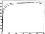
图2几种不同反射率材质的表面层高度~二维图像灰度映射关系曲线 Figure 2 The surface layer height of several different reflectivity materials and the two-dimensional image grayscale mapping relationship curve
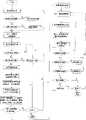
图3a不同反射率材质组合表面层三维宏观形貌构建系统第一种方案流程图 Figure 3a Flowchart of the first scheme of the three-dimensional macroscopic topography construction system of the surface layer combined with different reflectivity materials
图3b不同反射率材质组合表面层三维宏观形貌构建系统第二种方案流程图 Figure 3b Flowchart of the second scheme of the three-dimensional macroscopic topography construction system of the surface layer combined with different reflectivity materials
图4a两种不同反射率材质的多层表面俯视图 Figure 4a Top view of multi-layer surface with two different reflectivity materials
图4b两种不同反射率材质表面层高度~二维图像灰度映射关系曲线 Figure 4b The relationship curve between the surface layer height of two different reflectivity materials and the two-dimensional image grayscale mapping
图4c反射率k2表面所构建的三维宏观形貌图像 Figure 4c The three-dimensional macroscopic topography image constructed by the reflectivity k2 surface
图4d反射率k1表面所构建的三维宏观形貌图像 Figure 4d The three-dimensional macroscopic topography image constructed by the reflectivity k1 surface
图4e图4c,图4d两部分合起来的三维宏观形貌效果图 Figure 4e, Figure 4c, and Figure 4d are combined three-dimensional macroscopic appearance renderings
图4f图4a中所有表面反射率均取1时构建的三维宏观形貌图像 Figure 4f The three-dimensional macroscopic topography image constructed when all the surface reflectances in Figure 4a are taken as 1
图5a物体多层表面的俯视图 Figure 5a Top view of the multilayer surface of the object
图5b材质表面反射率k1,k2同取1时所构建的三维宏观形貌图像 Figure 5b The three-dimensional macroscopic topography image constructed when the surface reflectance k1 and k2 of the material are both taken as 1
图5c区分材质表面(左上、和右下区域反射值k1取0.5,左下、右上区域反射值k2取1)时所构建的三维宏观形貌图像 Figure 5c is the three-dimensional macroscopic topography image constructed when distinguishing the surface of the material (the reflection value k1 of the upper left and lower right areas is 0.5, and the reflection value k2 of the lower left and upper right areas is 1)
图6a浮雕艺术作品俯视摄影的二维图像 Figure 6a The two-dimensional image of the top-down photography of the relief artwork
图6b从图6a作品不同反射率材质表面构造的三维宏观形貌图像 Figure 6b is the three-dimensional macroscopic topography image of the surface structure of different reflectivity materials in the works in Figure 6a
图7a湖泊俯视遥感的二维图像 Figure 7a The two-dimensional image of the lake looking down on remote sensing
图7b从图7a不同反射率地表构造的三维宏观地貌图像 Figure 7b is the 3D macroscopic landform image of the surface structure with different reflectivity from Figure 7a
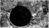
图8a脱落铆钉头的锅炉钢板表面照片 Figure 8a Photo of the surface of the boiler steel plate with the rivet head peeled off
图8b图8a的局部三维宏观形貌图像 The local three-dimensional macroscopic image of Fig. 8b and Fig. 8a
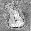
图9a铸钢样品磨面上的大型硅酸盐夹杂物照片 Fig.9a Photo of large silicate inclusions on the grinding surface of cast steel samples
图9b图9a的局部三维宏观形貌图像 The local three-dimensional macroscopic image of Figure 9b and Figure 9a
图10a热轧钢坯料磨面上的异金属夹杂物照片 Fig.10a Photo of dissimilar metal inclusions on the grinding surface of hot-rolled steel billet
图10b图10a的局部三维宏观形貌图像 The local three-dimensional macroscopic image of Figure 10b and Figure 10a
具体实施方式 用普通相机对物体宏观表面采样拍摄时,一般来说物距远大于相机镜头的焦距及像距,成像照度保持不变,即图像灰度不随相机与物体宏观表面距离的改变而改变。在这种光学成像条件下,相机视屏采集到的图像灰度率主要取决于光源与物体宏观表面的距离。 Specific implementation methods When using an ordinary camera to sample and shoot the macroscopic surface of an object, generally speaking, the object distance is far greater than the focal length and image distance of the camera lens, and the imaging illuminance remains unchanged, that is, the grayscale of the image does not change with the distance between the camera and the macroscopic surface of the object. . Under this optical imaging condition, the gray rate of the image captured by the camera screen mainly depends on the distance between the light source and the macroscopic surface of the object. the
我们用点光源或者扩展点光源辐射一个目标物,然后用相机拍摄目标物得到一幅二维图像,如果是连续图像必须转换成数字图像,如果是彩色图像还须转换成灰度图像,从这幅数字图像的灰度差映射物体表面层的高度差,建立表面层高度与图像灰度的映射关系模型。 We use a point light source or an extended point light source to irradiate a target, and then use a camera to shoot the target to get a two-dimensional image. If it is a continuous image, it must be converted into a digital image, and if it is a color image, it must be converted into a grayscale image. From this The gray level difference of two digital images is mapped to the height difference of the surface layer of the object, and the mapping relationship model between the surface layer height and image gray level is established. the
如图1所示一个扩展点光源照射两种不同反射率材质组成的表面层,点光源沿O′O″轴向的光源面元cosθdS以立体角dΩ向目标物的上下两层表面A′、A″辐射;cosθdS与沿光源法线N方向的dS之间有夹角为θ;目标物沿O′O″分为左右两半:左半反射率k1的材质的上下两层表面分别为A′1、A″1,右半反射值为k2的另一种材质的上下两层表面分别为A′2、A″2;目标物上下两层表面A′、A″分别与光源面元cosθdS的距离为h′、h″。 As shown in Figure 1, an extended point light source irradiates the surface layer composed of two materials with different reflectivity, and the light source surface element cosθdS of the point light source along the O'O" axis faces the upper and lower surfaces A', A"radiation; there is an angle θ between cosθdS and dS along the normal direction of the light source N; the target object is divided into left and right halves along O'O": the upper and lower surfaces of the material with the left half reflectance k1 are respectively A′1 , A″1 , the upper and lower surfaces of another material with a right semi-reflection value of k2 are A′2 , A″2 respectively; The distances of the element cosθdS are h′, h″.
一个被光线照射物体的表面的照度函数E为: The illuminance function E of a surface illuminated by light is:
上式dA是被光线照射目标物表面积A的面元,dΦ是dA上照射的光通量:dΦ=BdΩdScosθ(其中B为光源亮度)。 The above formula dA is the panel element of the surface area A of the object illuminated by the light, and dΦ is the luminous flux irradiated on dA: dΦ=BdΩdScosθ (where B is the brightness of the light source). the
式1表明光通量Φ不变时照度函数E与表面积A成反比,从图1看出被照射的圆面积A与其半径的平方r2成正比、也与光源面元cosθdS的距离的平方h2成正比,即照度函数E与距离的平方h2成反比:
因此,被点光源照射距离越远的目标物层面,照度越低;被点光源照射距离越近的目标物层面,照度越高;照度差可以映射目标物层面之间的高度差。 Therefore, the farther the target layer illuminated by the point light source, the lower the illuminance; the closer the target object layer illuminated by the point light source, the higher the illuminance; the difference in illuminance can map the height difference between the target object layers. the
一个简单的成像模型是: A simple imaging model is:
f(x,y)=i(x,y)r(x,y) (式3) f(x, y)=i(x, y)r(x, y) (Formula 3)
上式中图像函数f(x,y)可看成一个二维亮度函数(将图像看作一个光源),其亮度值范围:0<f(x,y)<∞;f(x,y)也表示一幅图像的灰度函数,其灰度值g范围:Gmin≤g≤Gmax;照度函数i(x,y)是入射到可见场景上的光量,其照度范围:0<i(x,y)<∞;反射函数r(x,y)具体为场景中目标物对入射光反射的比值,其反射范围:0<r(x,y)<1. In the above formula, the image function f(x, y) can be regarded as a two-dimensional brightness function (the image is regarded as a light source), and its brightness value range: 0<f(x, y)<∞; f(x, y) It also represents the grayscale function of an image, its grayscale value g range: Gmin ≤ g ≤ Gmax ; the illuminance function i(x, y) is the amount of light incident on the visible scene, and its illuminance range: 0<i( x, y)<∞; the reflection function r(x, y) is specifically the ratio of the reflection of the target object to the incident light in the scene, and its reflection range: 0<r(x, y)<1.
以照度函数E的表达式2取代式3中的照度函数i(x,y),且令同一材质的目标物不同层面对某点上方的相机的漫反射函数r(x,y)设为k值,得到: Replace the illuminance function i(x, y) in
即
上式中Gmin~Gmax为一幅二维图像灰度值g的范围,h是反射率为k的表面层高度。 In the above formula, Gmin ~ Gmax is the range of gray value g of a two-dimensional image, and h is the height of the surface layer with reflectivity k.
式5是同一反射率材质表面层高度~二维图像灰度的映射关系模型,如果是不同反射率材质的组合表面,某个反射率表面层高度~二维图像灰度映射关 系的子模型表达式是:
上式中Gimin~Gimax是某个二维子图像fi(xi,yi)灰度值gi的范围,hi是该子图像相应反射率ki表面层的第三维高度。 In the above formula, Gimin ~Gimax is the range of the gray value gi of a two-dimensional sub-image fi (xi, yi ), and hi is the third-dimensional height of the surface layer of the sub-image with corresponding reflectivityki .
因此要按组合表面的不同反射率材质对图像进行区域分割,分割成多个单一反射率表面的子图像,其区域分割的表达式是: Therefore, it is necessary to segment the image according to the different reflectivity materials of the combined surface, and divide it into multiple sub-images of a single reflectivity surface. The expression of the region segmentation is:
上式中f(x,y)是一幅二维数字灰度图像,fi(xi,yi)是分割成某个反射率ki子表面的子图像,Gimin~Gimax是它灰度值gi的范围。 In the above formula, f(x, y) is a two-dimensional digital grayscale image, fi (xi , yi ) is a sub-image divided into sub- surfaces with a certain reflectivity ki, and Gimin ~Gimax is its The range of gray value gi .
从分割出的多个单一反射率表面的二维子图像中,选定一个最小反射率表面的子图像作为基准,在这个基准子图像与其余子图像之间,在它们每一些相等的表面层高度上,可以导出表面反射率与图像灰度值的比例关系表达式,如式8: From the divided two-dimensional sub-images of a single reflectance surface, select a sub-image of the minimum reflectance surface as a reference, and between this reference sub-image and other sub-images, in each of them equal surface layers In terms of height, the proportional relationship expression between surface reflectance and image gray value can be derived, such as formula 8:
因此可以进一步用基准子图像灰度的加权来取代其余子图像,其表达式如式9: Therefore, the rest of the sub-images can be replaced by the weighting of the gray scale of the benchmark sub-image, the expression of which is shown in formula 9:
上两式中设f1(x1,y1)是1个最小反射率k1表面的子图像,fi(xi,yi)是其余n-1个反射率ki表面的子图像。 In the above two formulas, let f1 (x1 , y1 ) be a sub-image of a surface with minimum reflectivity k1 , and fi (xi , yi ) be the sub-images of the remaining n-1 surfaces with reflectance ki .
定义基准子图像f1(x,y)中零高度表面层的最小灰度为G1min值,其余n-1个子图像fi(xi,yi)中零高度表面层的最小灰度为Gimin,则其余子图像对应的多种反射率表面零高度层最小灰度表达式为: Define the minimum gray level of the zero-height surface layer in the reference sub-image f1 (x, y) as G1min value, and the minimum gray level of the zero-height surface layer in the remaining n-1 sub-images fi (xi, yi ) is Gimin , then the minimum gray level expression of the zero-height layer on the surface of various reflectances corresponding to the rest of the sub-images is:
按式7对不同反射率材质组合表面的一幅二维数字灰度图像进行区域分割之后,继而可以“二维分建三维——三维标高拼合”的第一种方案,也可以采用“二维灰度增强——二维合建三维”的第二种方案,完成不同反射率材质组合表面的三维宏观形貌图像的构建。 After dividing a two-dimensional digital grayscale image of a surface with different reflectivity material combinations according to Eq. The second scheme of "grayscale enhancement - two-dimensional joint construction of three-dimensional" completes the construction of three-dimensional macroscopic topography images of surfaces combined with different reflectivity materials. the
第一种方案中的“二维分建三维”是对分割出的单一反射率表面的二维子图像分别构建三维宏观形貌的子模型及其子系统,某个反射率表面层高度~二维图像灰度映射关系的子模型同式6;“三维标高拼合”则是用多个子表面层三维宏观形貌的子图像,按标高拼合成一幅完整表面层的三维宏观形貌图像,其表达式是: In the first scheme, "building 3D by dividing 2D" is to construct the sub-model and its subsystem of the 3D macroscopic topography for the 2D sub-image of the single reflectance surface segmented separately. The sub-model of the gray-scale mapping relationship of the three-dimensional image is the same as formula 6; "3D elevation combination" is to combine the sub-images of the three-dimensional macroscopic topography of multiple sub-surface layers into a complete three-dimensional macroscopic topography image of the surface layer according to the elevation. The expression is:
上式中fi(xi,yi,hi)是某个二维子图像fi(xi,yi)所构建的反射率ki表面层宏观形貌图像, 
第二种方案中“二维灰度增强”是按式9以基准子图像灰度的加权来逐个取代其余子图像,共同组合成一幅被改造的二维图像代替原始图像其表达式是: In the second scheme, "two-dimensional grayscale enhancement" is to replace the remaining subimages one by one with the weighting of the reference subimage grayscale according to formula 9, and jointly form a transformed two-dimensional image to replace the original image. The expression is:
上式中f1(x1,y1)是选作基准的最小反射率k1表面的1个子图像, 

第二种方案中“二维合建三维”是视这幅改造二维图像为输入图像,建立单一反射率k1表面层高度~二维图像灰度的映射关系子模型,其表达式是: In the second scheme, "two-dimensional co-construction of three-dimensional" is to regard the modified two-dimensional image as the input image, and establish a mapping relationship sub-model of single reflectance k1 surface layer height to the gray level of the two-dimensional image, and its expression is:
上式中f′(x,y)是所有n个子图像组合代替原始图像被改造的的一幅二维图像,h′是它相应表面层高度, 
一些典型的反射值k为:黑天鹅绒0.01,不锈钢0.65,粉刷的白墙面0.80,镀银器皿0.90,白雪0.93;假设黑天鹅绒的零高度层的灰度为1,则不锈钢为65,粉刷的白墙面为80,镀银器皿为90,白雪为93;因此这些不同反射率材质表面层高度~二维图像灰度的映射关系模型是: Some typical reflection values k are: 0.01 for black velvet, 0.65 for stainless steel, 0.80 for whitewashed walls, 0.90 for silver-plated utensils, and 0.93 for white snow; assuming that the gray level of the zero-height layer of black velvet is 1, the stainless steel is 65, and the whitewashed walls are 0.93. The white wall is 80, the silver-plated vessel is 90, and the white snow is 93; therefore, the mapping relationship model between the surface layer height of these different reflectivity materials and the gray level of the two-dimensional image is:

(65≤g≤G不锈钢max) (式15) (65≤g≤Gstainless steel max ) (Formula 15)
(80≤g≤G白粉墙max) (式16) (80≤g≤Gwhite powder wall max ) (Formula 16)


按照式14~18绘制出这些不同反射率材质表面层高度~二维图像灰度的映射关系曲线如图2所示。 According to formulas 14-18, the mapping relationship curves of the surface layer height of these different reflectance materials to the gray level of the two-dimensional image are drawn, as shown in Figure 2. the
本发明提供的上述不同反射率材质组合表面的三维宏观形貌构建方法,其效果通过安装在计算机的三维宏观形貌构建系统来实现,操作简便、易学易用和便于普及,只要按照以下具体方法步骤操作即可: The three-dimensional macro-topography construction method of the above-mentioned different reflectivity material combination surface provided by the present invention, its effect is realized by the three-dimensional macro topography construction system installed in the computer, easy to operate, easy to learn, easy to use and easy to popularize, as long as the following specific methods are followed Just follow the steps:
(1)采用点光源或者扩展点光源辐射物体表面,将数码相机对准物体表面的目标区域,避开强反光方向,使其表面漫反射光进入镜头,摄制出一幅数字图像;或者将一幅物体宏观表面的照片用扫描仪转换成数字图像;要求图像JPEC格式、256色灰度,图像分辨率为400~600DPI,图像中目标的框选区大小为10kb~1Mb。 (1) Use a point light source or an extended point light source to radiate the surface of the object, aim the digital camera at the target area on the surface of the object, avoid the direction of strong reflection, make the diffuse reflection light on the surface enter the lens, and take a digital image; A photo of the macroscopic surface of the object is converted into a digital image with a scanner; the image is required to be in JPEC format, 256-color gray scale, the image resolution is 400-600DPI, and the size of the frame selection area of the target in the image is 10kb-1Mb. the
(2)将上述物体表面的灰度数字图像输入计算机,在Windows XP操作系统和Matlab或VB语言开发的用户界面下,启动本发明根据上述不同反射率材质组合表面层高度~二维图像灰度的映射关系模型编程的三维宏观形貌构建系统,按照图3a第一种方案流程图所述的步骤操作:开始打开一幅不同反射率材质组合表面的二维数字图像,首先须要用户确认是否256级灰度图像?图像分辨率是否为400~600DPI?如不是则须要转化为灰度图像并调节图像分辨率;其次可以命令系统在工作窗口中显示这幅满足输入要求的二维数字灰度图像,允许用户在图像中多次框选、舍弃或保存感兴趣的区域,并使欲构建区域大小限制在10kb~1Mb;再者须要用户确定欲构建区域内不同反射率ki材质个数n,按不同反射率ki材质特征,逐一分割不同反射率ki材质诸表面形态各异的n个二维子图 像Pi,并加以显示和保存;接着就可以进入三维图像构建系统,在此逐一打开某个反射率ki材质子表面的二维子图像Pi,进行必要的直方图规定化处理,并输入反射率ki参数相应的三维图像构建子系统,逐一对每个二维子图像Pi进行三维构建,对得到的n个三维子图像Vi逐一显示和保存;最后在工作窗口中标高拼合n个三维子图像Vi成为原始二维图像构建的三维宏观形貌图像,注意旋转调节它们的视角方向保持一致;并以其中最小反射率k1子表面的1个二维子图像f1(x1,y1)的最小灰度G1min,即构成三维子图像f1(x1,y1,h1)的最小灰度G1min,作为整个表面层的零高度基准,其他n-1子表面层的零高度相应子图像的最小灰度是 按合成三维图像的视觉效果还要从以下三个方面确认:灰度反差适中吗?灰度层次清晰吗?三维视角满意吗?如不满意,则可以针对以上逐条分别进行灰度直方图规定化处理、灰度插值处理和调整视角的三维动画旋转;最终以JPEC格式存储这幅三维图像,即可完成对不同反射率材质组合表面层三维宏观形貌的实时构建。 (2) the gray scale digital image input computer of above-mentioned object surface, under the user interface that Windows XP operating system and Matlab or VB language develop, start the present invention according to above-mentioned different reflectivity material combination surface layer height~two-dimensional image gray scale The 3D macro-topography construction system programmed by the mapping relationship model operates according to the steps described in the flow chart of the first scheme in Figure 3a: start to open a 2D digital image of a surface with different reflectivity material combinations, and firstly the user needs to confirm whether 256 level grayscale image? Is the
(3)按照图3b三维宏观形貌构建系统第二种方案流程图所述的操作步骤:“……按不同反射率ki材质特征,逐一分割不同反射率ki材质的形态各异的每个二维子图像Pi,并加以显示和保存”之前与图3a三维宏观形貌构建系统流程图之一所述的操作步骤相同;接下来须要用反射率之比例系数值ki/k1分别加权n-1个子图像Pi,合成1个基准子图像P1与n-1个加权后的子图像 
实施例1:图4a所示两种不同反射率材质的多层表面俯视图,其中所标数字4,5诸表面的反射率k1值是所标数字1,2,3诸表面的反射率k2值的2倍,尽管目视二者的最高表面3与4的灰度大致相当,1与5的灰度大致相当,但预计4的实际高度可能会比3低得多,1的实际高度可能会比5高得多;图4b所示两种不同反射率材质表面层高度~二维图像灰度的映射关系曲线;根据图4b映射关系曲线分别建立两种反射率材质的三维宏观形貌图像如图4c、图4d;最后将两部分合起来得到的效果图如图4e,正如所料;如果图4a所示所有表面1,2,3,4,5的反射率均取1时构建的三维宏观形貌图像如图4f。 Embodiment 1: the multilayer surface plan view of two kinds of different reflectivity materials shown in Fig. 4 a, wherein the reflectivityk value of marked
实施例2:图5a所示材质多层表面的俯视灰度图;若为同一种材质(表面层反射率k1,k2同取1时),所构建的三维模型如图5b,这是一个前后、左右在高度方向对称的三维图像;若为组合材料(左上、和右下区域反射率k1取0.5,左下、右上区域反射率k2取1),所构建的三维宏观形貌图像如图5c,可以看出对角上的同种材质关于中心才是对称的;这就是单一反射率材质与不同反射率组合材质在表面层三维宏观形貌构建的重要区别。 Embodiment 2: the top view grayscale image of the multilayer surface of the material shown in Figure 5a; if it is the same material (when the surface layer reflectance k1 and k2 are taken as 1), the three-dimensional model constructed is as shown in Figure 5b, which is A three-dimensional image that is symmetrical in the height direction from front to back and left to right; if it is a composite material (the reflectance k1 of the upper left and lower right regions is taken as 0.5, and the reflectance k of the lower left and upper right regions is taken as1 ), the constructed three-dimensional macroscopic image As shown in Figure 5c, it can be seen that the same material on the diagonal is symmetrical about the center; this is an important difference between a single reflectance material and a combination of materials with different reflectances in the construction of the three-dimensional macroscopic topography of the surface layer.
实施例3:图6a所示一件浮雕艺术作品的二维俯视灰度图,其中发亮的红铜质马车浮雕嵌镶在栗子色的木质薄板上,板面下方还粘贴着印有文字的黄铜质薄片;图6b是按本发明方法(图3a第一种方案流程图)对图6a构建的三维宏观形貌图像,可以看到:由黄铜质薄片、红铜马车浮雕、木质薄板三种反射值不同的组合材质分别构建,最终合成的三维宏观形貌图像,其第三维厚度差 符合该浮雕作品实际情况。 Example 3: A two-dimensional top view grayscale image of a relief art work shown in Figure 6a, in which the shiny red copper carriage relief is inlaid on a chestnut-colored wooden veneer, and a letter with printed text is pasted on the bottom of the plate. Brass thin slice; Fig. 6 b is the three-dimensional macro-topography image constructed to Fig. 6 a according to the method of the present invention (Fig. Three combined materials with different reflection values were constructed separately, and the finally synthesized three-dimensional macroscopic topography image, whose third-dimensional thickness difference conforms to the actual situation of the relief work. the
实施例4:图7a所示湖泊的二维俯视遥感图像,其中湖泊为黑色区域,其余灰色为陆地,显然二者反射率不同,将二者分割处理再按本发明方法(图3b第二种方案流程图)构建三维地貌图像如图7b,可以看到湖泊及其周边的高度关系。 Embodiment 4: the two-dimensional overlooking remote sensing image of the lake shown in Figure 7a, wherein the lake is a black area, and all the other grays are land, obviously the reflectance of the two is different, and the two are divided and processed according to the method of the present invention (the second type of Figure 3b Scheme flow chart) Constructing a three-dimensional landform image as shown in Figure 7b, you can see the height relationship between the lake and its surroundings. the
实施例5:图8a照片所示锅炉钢板表面的铆钉头脱落,露出的黑色断口肉眼看不清楚,为典型的应力腐蚀(苛性腐蚀)断裂。从图像上看,黑色断口表面与钢板表面基本平齐,但属于反射率不同的两种材质,如果按同一种反射率建立二维图像灰度与表面层高度的映射关系模型,构建的表面层三维宏观形貌就会使黑色断口部分深陷钢板之中。图8b是按照本发明方法构建的局部表面层三维宏观形貌,其图像保持黑色断口部分同钢板表面平齐,并且较好地恢复了图8a俯视图像所丢失的第三维深度信息,将黑色断口表面的氧化物颗粒形态如实再现出来。 Example 5: The rivet head on the surface of the boiler steel plate shown in the photo of Fig. 8a falls off, and the exposed black fracture is not clearly visible to the naked eye, which is a typical stress corrosion (caustic corrosion) fracture. From the image, the black fracture surface is basically flush with the steel plate surface, but they belong to two materials with different reflectivity. If the mapping relationship model between the two-dimensional image gray level and the surface layer height is established according to the same reflectivity, the surface layer The three-dimensional macroscopic shape will make the black fracture part sink deep into the steel plate. Fig. 8b is the three-dimensional macroscopic topography of the local surface layer constructed according to the method of the present invention. The image keeps the black fracture part flush with the steel plate surface, and better restores the third-dimensional depth information lost in the top view image of Fig. 8a, and the black fracture The morphology of the oxide particles on the surface is faithfully reproduced. the
实施例6:图9a所示铸钢样品磨面上的大型硅酸盐夹杂物,凭此图看不出三维空间的硅酸盐如何夹杂于铸钢之内,甚至误作一条深裂缝,但我们注意到硅酸盐夹杂物的反射率远低于铸钢样品磨面,浅灰色部分同铸钢样品表面一起磨齐。图9b是按照本发明方法构建的局部表面层三维宏观形貌,从周边剖切断面上可以读出浅灰色的硅酸盐夹杂嵌镶在铸钢之内所占据空间的深度约1.5mm,黑色空隙是磨制表面时部分夹杂脱落的结果。 Example 6: Large-scale silicate inclusions on the grinding surface of the cast steel sample shown in Figure 9a. From this figure, it is impossible to see how the three-dimensional silicate is included in the cast steel, and even a deep crack is mistakenly made, but We noticed that the reflectance of the silicate inclusions is much lower than that of the ground surface of the cast steel sample, and the light gray part is ground together with the surface of the cast steel sample. Figure 9b is the three-dimensional macroscopic appearance of the local surface layer constructed according to the method of the present invention. From the peripheral section, it can be read that the depth of the space occupied by the light gray silicate inclusions embedded in the cast steel is about 1.5mm, and the black Voids are the result of partial inclusions falling off when the surface is ground. the
实施例7:图10a所示热轧钢胚磨面上的大块异金属夹杂物,夹杂物中有内裂,两种反射率不同的材料交界处黑色缝隙勾画了异金属夹杂物的轮廓,还有较多非金属夹杂经热蝕后形成的孔洞。图10b是按照本发明方法对图10a构建的局部表面层三维宏观形貌,从图中可看出钢铁金属与异金属在一个高度的磨面上,从三维宏观形貌的侧剖面能够测出金属夹杂物内裂的深度约0.5mm,周边非金属夹杂经热蝕后形成的孔洞深度约0.05mm。Example 7: Large heterometallic inclusions on the grinding surface of the hot-rolled steel billet shown in Figure 10a. There are internal cracks in the inclusions. The black gap at the junction of two materials with different reflectivities outlines the outline of the heterometallic inclusions. There are also many holes formed by non-metallic inclusions after thermal etching. Figure 10b is the three-dimensional macroscopic topography of the local surface layer constructed in accordance with the method of the present invention in Fig. The depth of internal cracking of metal inclusions is about 0.5mm, and the depth of holes formed by surrounding non-metallic inclusions after thermal etching is about 0.05mm.
以上实施例表明:在观察与检测物体表面状态极其质量的多个科学技术领域,本发明所述方法针对不同反射率材质组合表面的一幅二维数字灰度图像构建三维宏观形貌,改造了以面代体的传统图像观测技术弊端,有恢复第三维视觉信息的重大实用价值。实时构建三维宏观形貌图像,显示客观、立体感强、视角可变、易于测量、成本较低、便于普及。最有特色的一点是:框选二维灰度图像中感兴趣的区域时,从本发明虚拟的三维造像上就能轻而易举得到穿越目标(特别是细小的缺陷)的横剖面,进而可以从横剖面度量其深度;即使对现实的制件切割取样,也不可能做得如此轻易、如此精细、如此准确,因此它又是以虚代实、以虚测实的创造性的无损检验方法。 The above embodiments show that: in the fields of science and technology for observing and detecting the surface state of objects and their quality, the method of the present invention constructs a three-dimensional macroscopic image for a two-dimensional digital grayscale image of a surface composed of materials with different reflectivity, and transforms the The disadvantages of traditional image observation technology that replaces body with surface have great practical value in recovering the third-dimensional visual information. Real-time construction of three-dimensional macroscopic topography images, objective display, strong three-dimensional sense, variable viewing angle, easy measurement, low cost, and easy popularization. The most distinctive point is: when selecting the region of interest in the two-dimensional grayscale image, the cross-section of the target (especially small defects) can be easily obtained from the virtual three-dimensional imaging of the present invention, and then the The section measures its depth; even cutting and sampling the actual workpiece, it is impossible to do it so easily, so finely, and so accurately. Therefore, it is a creative non-destructive testing method that replaces the real with the virtual and measures the real with the virtual. the
Claims (3)
Translated fromChinese


Priority Applications (1)
| Application Number | Priority Date | Filing Date | Title |
|---|---|---|---|
| CN2010102331725ACN101907450B (en) | 2010-07-22 | 2010-07-22 | Construction method of three-dimensional macro morphology of combined surface containing materials with different reflectivities |
Applications Claiming Priority (1)
| Application Number | Priority Date | Filing Date | Title |
|---|---|---|---|
| CN2010102331725ACN101907450B (en) | 2010-07-22 | 2010-07-22 | Construction method of three-dimensional macro morphology of combined surface containing materials with different reflectivities |
Publications (2)
| Publication Number | Publication Date |
|---|---|
| CN101907450A CN101907450A (en) | 2010-12-08 |
| CN101907450Btrue CN101907450B (en) | 2012-05-23 |
Family
ID=43262975
Family Applications (1)
| Application Number | Title | Priority Date | Filing Date |
|---|---|---|---|
| CN2010102331725AExpired - Fee RelatedCN101907450B (en) | 2010-07-22 | 2010-07-22 | Construction method of three-dimensional macro morphology of combined surface containing materials with different reflectivities |
Country Status (1)
| Country | Link |
|---|---|
| CN (1) | CN101907450B (en) |
Families Citing this family (4)
| Publication number | Priority date | Publication date | Assignee | Title |
|---|---|---|---|---|
| TWI526990B (en)* | 2014-09-15 | 2016-03-21 | 三緯國際立體列印科技股份有限公司 | Image processing method for transforming 2d image into 3d model |
| CN109087347B (en)* | 2018-08-15 | 2021-08-17 | 浙江光珀智能科技有限公司 | Image processing method and device |
| CN111238370A (en)* | 2020-02-20 | 2020-06-05 | 中国科学院声学研究所东海研究站 | Intelligent detection method and device for KIT board |
| CN114979442B (en)* | 2022-05-25 | 2023-10-31 | 西南科技大学 | Multipath image acquisition device and control method thereof |
Citations (6)
| Publication number | Priority date | Publication date | Assignee | Title |
|---|---|---|---|---|
| US5289267A (en)* | 1991-10-04 | 1994-02-22 | Kms Fusion, Inc. | Electro-optical system for gauging surface profile deviations |
| CN1376895A (en)* | 2001-03-25 | 2002-10-30 | 欧姆龙株式会社 | Optical metering installation |
| CN1206612C (en)* | 1999-09-10 | 2005-06-15 | 索尼计算机娱乐公司 | Method and apparatus for recreating reflective textured surfaces with distortion |
| CN101000296A (en)* | 2006-12-20 | 2007-07-18 | 西北师范大学 | Method of 3D reconstruction metallographic structure microproject based on digital image technology |
| US7391523B1 (en)* | 2003-06-02 | 2008-06-24 | K-Space Associates, Inc. | Curvature/tilt metrology tool with closed loop feedback control |
| JP2009204449A (en)* | 2008-02-28 | 2009-09-10 | Topcon Corp | Target and three-dimensional shape measuring device using it |
- 2010
- 2010-07-22CNCN2010102331725Apatent/CN101907450B/ennot_activeExpired - Fee Related
Patent Citations (6)
| Publication number | Priority date | Publication date | Assignee | Title |
|---|---|---|---|---|
| US5289267A (en)* | 1991-10-04 | 1994-02-22 | Kms Fusion, Inc. | Electro-optical system for gauging surface profile deviations |
| CN1206612C (en)* | 1999-09-10 | 2005-06-15 | 索尼计算机娱乐公司 | Method and apparatus for recreating reflective textured surfaces with distortion |
| CN1376895A (en)* | 2001-03-25 | 2002-10-30 | 欧姆龙株式会社 | Optical metering installation |
| US7391523B1 (en)* | 2003-06-02 | 2008-06-24 | K-Space Associates, Inc. | Curvature/tilt metrology tool with closed loop feedback control |
| CN101000296A (en)* | 2006-12-20 | 2007-07-18 | 西北师范大学 | Method of 3D reconstruction metallographic structure microproject based on digital image technology |
| JP2009204449A (en)* | 2008-02-28 | 2009-09-10 | Topcon Corp | Target and three-dimensional shape measuring device using it |
Also Published As
| Publication number | Publication date |
|---|---|
| CN101907450A (en) | 2010-12-08 |
Similar Documents
| Publication | Publication Date | Title |
|---|---|---|
| Apollonio et al. | A photogrammetry-based workflow for the accurate 3D construction and visualization of museums assets | |
| CN109580630B (en) | Visual inspection method for defects of mechanical parts | |
| Meilland et al. | 3d high dynamic range dense visual slam and its application to real-time object re-lighting | |
| CN100495441C (en) | A method for constructing three-dimensional macroscopic morphology of metal surface layer based on digital image technology | |
| CN108682012B (en) | A 3D curved glass surface flatness defect detection method based on line scan laser | |
| CN107677216B (en) | A kind of multiple abrasive grain three-dimensional appearance synchronous obtaining methods based on photometric stereo vision | |
| JP6407607B2 (en) | Method and apparatus for digitally generating appearance data | |
| Pintus et al. | State‐of‐the‐art in Multi‐Light Image Collections for surface visualization and analysis | |
| US20030231175A1 (en) | Image-based 3D modeling rendering system | |
| TW200415526A (en) | System, method and program of visualization process | |
| Hess et al. | Application of multi-modal 2D and 3D imaging and analytical techniques to document and examine coins on the example of two Roman silver denarii | |
| CN101907450B (en) | Construction method of three-dimensional macro morphology of combined surface containing materials with different reflectivities | |
| MacDonald et al. | Three-dimensional reconstruction of Roman coins from photometric image sets | |
| CN116087036A (en) | Device for identifying images of sediment plume of deep sea mining and image analysis method | |
| Valente et al. | Methods for ancient wall graffiti documentation: overview and applications | |
| Watteeuw et al. | Light, shadows and surface characteristics: the multispectral portable light dome | |
| Giachetti et al. | Multispectral RTI analysis of heterogeneous artworks | |
| Bigerelle et al. | Fractal and statistical characterization of brushstroke on paintings | |
| CN111161227B (en) | A bullseye positioning method and system based on deep neural network | |
| JP4335589B2 (en) | How to model a 3D object | |
| Graham et al. | Epic dimensions: a comparative analysis of 3D acquisition methods | |
| Rodrigue et al. | Lighting in the third dimension: Laser scanning as an architectural survey and representation method | |
| Min et al. | Digital imaging methods for painting analysis: the application of RTI and 3D scanning to the study of brushstrokes and paintings | |
| Djuricic et al. | High-resolution 3D surface modeling of a fossil oyster reef | |
| CN105022995B (en) | Method for extracting and analyzing diffusion and permeation information of painting and calligraphy elements based on light intensity information |
Legal Events
| Date | Code | Title | Description |
|---|---|---|---|
| C06 | Publication | ||
| PB01 | Publication | ||
| C10 | Entry into substantive examination | ||
| SE01 | Entry into force of request for substantive examination | ||
| C14 | Grant of patent or utility model | ||
| GR01 | Patent grant | ||
| CF01 | Termination of patent right due to non-payment of annual fee | Granted publication date:20120523 Termination date:20150722 | |
| EXPY | Termination of patent right or utility model |