CN101905046B - Micro-dose flow regulator - Google Patents
Micro-dose flow regulatorDownload PDFInfo
- Publication number
- CN101905046B CN101905046BCN2010102660741ACN201010266074ACN101905046BCN 101905046 BCN101905046 BCN 101905046BCN 2010102660741 ACN2010102660741 ACN 2010102660741ACN 201010266074 ACN201010266074 ACN 201010266074ACN 101905046 BCN101905046 BCN 101905046B
- Authority
- CN
- China
- Prior art keywords
- hole
- lower house
- upper shell
- infusion
- groove
- Prior art date
- Legal status (The legal status is an assumption and is not a legal conclusion. Google has not performed a legal analysis and makes no representation as to the accuracy of the status listed.)
- Active
Links
- 238000001802infusionMethods0.000claimsabstractdescription52
- 238000007789sealingMethods0.000claimsdescription13
- 230000001105regulatory effectEffects0.000claimsdescription2
- 239000012530fluidSubstances0.000claims4
- 239000007788liquidSubstances0.000abstractdescription28
- 239000000203mixtureSubstances0.000description4
- 238000004891communicationMethods0.000description3
- 238000010586diagramMethods0.000description3
- 239000003814drugSubstances0.000description3
- 230000000202analgesic effectEffects0.000description1
- 230000007812deficiencyEffects0.000description1
- 229940079593drugDrugs0.000description1
- 239000003978infusion fluidSubstances0.000description1
- 238000000034methodMethods0.000description1
- 239000000243solutionSubstances0.000description1
Images


Landscapes
- Infusion, Injection, And Reservoir Apparatuses (AREA)
Abstract
Translated fromChinese
Description
Translated fromChinese技术领域technical field
本发明涉及一种医用输液器流量调节装置,具体地说是一种输液器微剂量流量调节器。The invention relates to a flow regulating device for a medical infusion set, in particular to a micro-dosage flow regulator for an infusion set.
背景技术Background technique
我们知道,传统的输液器流量调节器安装在输液导管的外部,通过压轮压迫导管,实现对输液器流量调节。该结构的流量调节器流量调节精度低,流量不可测量,医护人员只能凭经验数滴斗内液滴滴数来估计流量,增加了医护人员的工作负担,上述流量调节器很难对流速进行有效控制。目前,也有微剂量流量调节器,如专利号为ZL02135801X的中国发明专利精密镇痛输液器,其中公开了一种其微剂量流量调节器,由转动盘、上壳体、下壳体、中心套组成。上壳体底端面设有一周环形凹槽,下壳体上端面设有一周环形凹槽。上壳体和下壳体通过中心套连接固定,转动盘夹在上壳体和下壳体之间,可相对上壳体和下壳体转动。转动盘与上壳体、下壳体接触的端面分别设有一周由深到浅的刻槽,刻槽最深处中设有一通孔。使用时,通过旋转转动盘,由上壳体、下壳体通孔对应处转动盘的刻槽深浅控制输液流量。可以精确、微量调节输液流量。但其结构组成复杂,特别是由于转动盘上存在一周由深到浅的刻槽,导致药液残留量大。不适合一些特殊药物小流量输注的流量控制。As we know, the flow regulator of the traditional infusion set is installed outside the infusion catheter, and the pressure wheel is used to press the catheter to realize the flow adjustment of the infusion set. The flow adjustment accuracy of the flow regulator with this structure is low, and the flow rate cannot be measured. The medical staff can only estimate the flow rate based on the number of drops in the drop bucket based on experience, which increases the workload of the medical staff. It is difficult for the above-mentioned flow regulator to adjust the flow rate. Effective control. At present, there are also micro-dosage flow regulators, such as the Chinese invention patent precision analgesic infusion set with the patent number ZL02135801X, which discloses a micro-dosage flow regulator, which consists of a rotating disc, an upper casing, a lower casing, and a center sleeve. composition. A circular groove is provided on the bottom surface of the upper casing, and a circular groove is provided on the upper surface of the lower casing. The upper casing and the lower casing are connected and fixed through the center sleeve, and the rotating disk is sandwiched between the upper casing and the lower casing, and can rotate relative to the upper casing and the lower casing. The end faces of the rotating disk in contact with the upper shell and the lower shell are respectively provided with a circle of engraved grooves from deep to shallow, and a through hole is arranged in the deepest part of the engraved grooves. When in use, by rotating the rotating disk, the infusion flow rate is controlled by the groove depth of the rotating disk corresponding to the through holes of the upper casing and the lower casing. The infusion flow can be precisely and micro-adjusted. But its structure is complex, especially because there is a circle of grooves from deep to shallow on the rotating disk, resulting in a large amount of liquid medicine residue. Not suitable for flow control of small flow infusion of some special drugs.
发明内容Contents of the invention
本发明所要解决的技术问题是克服上述现有技术的不足,提供一种结构合理,操作、使用简便,可减轻医护人员的工作负担,流量调节精确、稳定,且可随意调节的微剂量流量调节器。The technical problem to be solved by the present invention is to overcome the deficiencies of the above-mentioned prior art, and provide a micro-dosage flow regulator with reasonable structure, easy operation and use, which can reduce the workload of medical staff, accurate and stable flow regulation, and can be adjusted at will. device.
本发明解决上述技术问题采用的技术方案是:一种微剂量流量调节器,其包括上壳体、下壳体,上壳体中设有进液导管接头,下壳体中设有出液导管接头,上壳体、下壳体通过中心卡扣相互连接,可相对转动,其特征在于:所说上壳体底端面径向设有一与进液导管接头连通的细长通孔,下壳体上端面与上壳体底端面接触,下壳体上端面对应上壳体底端面的细长通孔设有一由窄到宽的变径输液凹槽,变径输液凹槽的最宽处设有一与出液导管接头连通的出液圆通孔,上壳体细长通孔、下壳体上端面的变径输液凹槽和出液圆通孔形成连通的输液通道,细长通孔对应的变径输液凹槽的宽窄,是输液流量的控制点,通过相对旋转上壳体和下壳体,调整细长通孔对应的变径输液凹槽的宽窄,实现对输液流量的精确、微量调节。The technical solution adopted by the present invention to solve the above technical problems is: a micro-dosage flow regulator, which includes an upper casing and a lower casing, the upper casing is provided with a liquid inlet conduit joint, and the lower casing is provided with a liquid outlet conduit The joint, the upper shell and the lower shell are connected to each other through the central buckle, and can be rotated relative to each other. The upper end surface is in contact with the bottom end surface of the upper casing, and the upper end surface of the lower casing corresponds to the elongated through hole on the bottom end surface of the upper casing. There is a liquid outlet circular through hole connected with the liquid outlet conduit joint. The upper shell slender through hole, the variable diameter infusion groove on the upper end surface of the lower shell and the liquid outlet round through hole form a connected infusion channel. The elongated through hole corresponds to a variable The width of the diameter infusion groove is the control point of the infusion flow. By relatively rotating the upper casing and the lower casing, the width of the variable diameter infusion groove corresponding to the elongated through hole is adjusted to realize precise and micro-adjustment of the infusion flow.
本发明所说的下壳体上端面上变径输液凹槽为环形变径输液凹槽。The variable-diameter infusion groove on the upper end surface of the lower housing in the present invention is an annular variable-diameter infusion groove.
本发明所说的下壳体上端面上变径输液凹槽的内、外分别设有环形密封槽,环形密封槽中安装有密封圈。According to the present invention, ring-shaped sealing grooves are arranged on the inside and outside of the variable-diameter infusion groove on the upper end surface of the lower casing, and sealing rings are installed in the ring-shaped sealing grooves.
本发明所说的下壳体外侧设有的竖条状凸起。方便手持转动。The vertical strip-shaped protrusions provided on the outer side of the lower casing in the present invention. Easy to hold and turn.
本发明采用上述组成、结构,上壳体底端面设有一细长通孔,下壳体与上壳体接触的上端面设有一由窄到宽的变径输液凹槽,使用时,通过相对旋转上壳体、下壳体,细长通孔对应处的变径输液凹槽宽窄控制输液流量。对照现有技术,本发明构造简单,操作、使用简便,可减轻医护人员的工作负担,流量调节精确、稳定,且可随意调节,药液残留量小。特别适用于对输液流量要求控制准确、稳定的患者使用。The present invention adopts the above-mentioned composition and structure. The bottom surface of the upper casing is provided with a slender through hole, and the upper surface of the lower casing in contact with the upper casing is provided with a variable-diameter infusion groove from narrow to wide. When in use, through relative rotation The width of the variable-diameter infusion groove corresponding to the upper shell, the lower shell, and the elongated through hole controls the infusion flow. Compared with the prior art, the present invention is simple in structure, easy to operate and use, can reduce the workload of medical personnel, has accurate and stable flow adjustment, and can be adjusted at will, and the residual amount of liquid medicine is small. It is especially suitable for patients who require accurate and stable control of infusion flow.
附图说明Description of drawings
下面结合附图对本发明作进一步的描述。The present invention will be further described below in conjunction with the accompanying drawings.
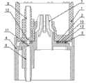
图1是本发明组成结构示意图。Fig. 1 is a schematic diagram of the composition and structure of the present invention.
图2是本发明上壳体底端面的示意图。Fig. 2 is a schematic view of the bottom end surface of the upper casing of the present invention.
图3是本发明下壳体上端面的示意图。Fig. 3 is a schematic view of the upper end surface of the lower casing of the present invention.
图4是本发明输液通道流量调节变化原理示意图。Fig. 4 is a schematic diagram of the changing principle of the flow regulation of the infusion channel according to the present invention.
图中1.上壳体,2.内密封圈,3.外密封圈,4.下壳体,5.进液导管接头,6.出液导管接头,7.中心卡扣,8.外密封槽,9.内密封槽,10.变径封堵面,11.出液圆通孔,12.细长通孔,13.变径输液凹槽。In the figure 1. Upper housing, 2. Inner sealing ring, 3. Outer sealing ring, 4. Lower housing, 5. Inlet conduit connector, 6. Outlet conduit connector, 7. Center buckle, 8. Outer seal Groove, 9. inner sealing groove, 10. variable diameter sealing surface, 11. liquid outlet round through hole, 12. elongated through hole, 13. variable diameter infusion groove.
具体实施方式Detailed ways
从图1中可以看出,一种微剂量流量调节器,其包括上壳体1、下壳体4,上壳体1中设有进液导管接头5,下壳体4中设有出液导管接头6,上壳体1、下壳体4通过中心卡扣7相互连接,可相对转动。微剂量流量调节器组装于输液器滴斗和过滤器之间,液体通过导管从上壳体1的进液导管接头5进入,从下壳体4的出液导管接头6连接导管流出。中心卡扣7的具体组成、连接属于现有技术,不再赘述。As can be seen from Figure 1, a micro-dosage flow regulator comprises an upper housing 1 and a
本发明的特点是:所说上壳体1底端面径向设有一与进液导管接头5连通的细长通孔12,如图1、图2所示。下壳体4上端面与上壳体1底端面接触,下壳体4上端面对应上壳体底端面的细长通孔12设有一由窄到宽的变径输液凹槽13,变径输液凹槽13的最宽处设有一与出液导管接头6连通的出液圆通孔11,上壳体细长通孔12、下壳体上端面的变径输液凹槽13和出液圆通孔11形成连通的输液通道,如图1、图3所示。The feature of the present invention is: the bottom end surface of the upper casing 1 is radially provided with an elongated through
从图1、图3中还可以看出,本发明所说的下壳体4上端面上对应上壳体底端面的细长通孔12的变径输液凹槽13为环形变径输液凹槽。相应的,与细长通孔12接触配合封堵的端面为环形变径封堵面10。It can also be seen from Fig. 1 and Fig. 3 that the variable-
本发明所说的下壳体4上端面上变径输液凹槽13的内、外分别设有环形内密封槽9、外密封槽8、环形内密封槽9、外密封槽8中分别安装有内密封圈2和外密封圈3。这样是相接触的端面密封更可靠。本发明所说的下壳体外侧设有的竖条状凸起。方便下壳体4相对上壳体1的手持转动。The inside and outside of the variable-
图4是本发明输液通道流量调节变化原理示意图。图4表示的是相对转动上壳体1和下壳体4时,细长通孔12与变径输液凹槽13的若干个对应位置状态。从图4中可以看出,相对转动上壳体1和下壳体4,变径封堵面10封堵细长通孔12的面积逐渐变大,细长通孔12与变径输液凹槽13的连通间隙就逐渐变小,进入变径输液凹槽13的液体流量就变少;反之,变径封堵面10封堵细长通孔12的面积逐渐变小,细长通孔12与变径输液凹槽13的连通间隙就逐渐变大,进入变径输液凹槽13的液体流量就变多。这样,细长通孔12对应的变径输液凹槽13的宽窄,是输液流量的控制点,通过相对旋转上壳体1和下壳体4,调整细长通孔对应的变径输液凹槽的宽窄,实现对输液流量的精确、微量调节。并且可以根据患者的要求对流速进行任意连续调节。Fig. 4 is a schematic diagram of the changing principle of the flow regulation of the infusion channel according to the present invention. FIG. 4 shows several corresponding positions of the elongated through
本发明使用时其装于输液器滴斗和过滤器之间,液体首先通过上壳体1的进液导管进入微剂量流量调节器,经过细长通孔12与下壳体3上的变径输液凹槽13的连通间隙,进入输液通道,最后从下壳体4连接的出液导管流出。通过相对旋转上壳体1和下壳体4,调整细长通孔对应的变径输液凹槽的宽窄,达到对流量调节的目的。在产品上相应位置进行流量刻度标识,使用时只需转动到相应的流量刻度,便可实现对流速的精确控制。实现对输液流量的精确、微量调节。When the present invention is in use, it is installed between the drip funnel of the infusion set and the filter. The liquid first enters the micro-dose flow regulator through the liquid inlet conduit of the upper casing 1, and passes through the elongated through
Claims (3)
Priority Applications (1)
| Application Number | Priority Date | Filing Date | Title |
|---|---|---|---|
| CN2010102660741ACN101905046B (en) | 2010-08-30 | 2010-08-30 | Micro-dose flow regulator |
Applications Claiming Priority (1)
| Application Number | Priority Date | Filing Date | Title |
|---|---|---|---|
| CN2010102660741ACN101905046B (en) | 2010-08-30 | 2010-08-30 | Micro-dose flow regulator |
Publications (2)
| Publication Number | Publication Date |
|---|---|
| CN101905046A CN101905046A (en) | 2010-12-08 |
| CN101905046Btrue CN101905046B (en) | 2012-07-04 |
Family
ID=43260727
Family Applications (1)
| Application Number | Title | Priority Date | Filing Date |
|---|---|---|---|
| CN2010102660741AActiveCN101905046B (en) | 2010-08-30 | 2010-08-30 | Micro-dose flow regulator |
Country Status (1)
| Country | Link |
|---|---|
| CN (1) | CN101905046B (en) |
Families Citing this family (5)
| Publication number | Priority date | Publication date | Assignee | Title |
|---|---|---|---|---|
| CN103933643A (en)* | 2014-04-29 | 2014-07-23 | 河南莲花医疗用品有限公司 | Infusion device flow fine-adjustment device |
| CN106110440A (en)* | 2016-06-08 | 2016-11-16 | 刁春林 | A kind of various flow adjusting means for trace anesthesia |
| CN112220994A (en)* | 2020-09-27 | 2021-01-15 | 江阴市鸿萌橡塑制品有限公司 | Micro-flow regulator for transfusion |
| CN114109806B (en)* | 2021-11-26 | 2022-12-13 | 深圳华星恒泰泵阀有限公司 | Electromagnetic pump with adjustable flow |
| CN116139364A (en)* | 2023-01-12 | 2023-05-23 | 上海必趣医疗科技有限公司 | An adjustable precision flow control device |
Citations (6)
| Publication number | Priority date | Publication date | Assignee | Title |
|---|---|---|---|---|
| CN2360088Y (en)* | 1999-01-14 | 2000-01-26 | 山东省威海医用高分子制品一厂 | Flow regulator |
| CN2579439Y (en)* | 2002-09-23 | 2003-10-15 | 佛山特种医用导管有限责任公司 | Flow regulator for infusion |
| CN1498660A (en)* | 2002-11-08 | 2004-05-26 | 山东威高集团医用高分子制品股份有限 | Precision analgesic infusion set |
| CN201094782Y (en)* | 2007-09-17 | 2008-08-06 | 佛山特种医用导管有限责任公司 | Infusion flow adjuster and liquid controlling valve thereof |
| CN101432034A (en)* | 2006-05-03 | 2009-05-13 | Gvs有限公司 | Improved sealed device for regulating the flow rate of a medical fluid directed to a patient |
| CN201759934U (en)* | 2010-08-30 | 2011-03-16 | 威海威高医用材料有限公司 | Micro-dose flow regulator |
- 2010
- 2010-08-30CNCN2010102660741Apatent/CN101905046B/enactiveActive
Patent Citations (6)
| Publication number | Priority date | Publication date | Assignee | Title |
|---|---|---|---|---|
| CN2360088Y (en)* | 1999-01-14 | 2000-01-26 | 山东省威海医用高分子制品一厂 | Flow regulator |
| CN2579439Y (en)* | 2002-09-23 | 2003-10-15 | 佛山特种医用导管有限责任公司 | Flow regulator for infusion |
| CN1498660A (en)* | 2002-11-08 | 2004-05-26 | 山东威高集团医用高分子制品股份有限 | Precision analgesic infusion set |
| CN101432034A (en)* | 2006-05-03 | 2009-05-13 | Gvs有限公司 | Improved sealed device for regulating the flow rate of a medical fluid directed to a patient |
| CN201094782Y (en)* | 2007-09-17 | 2008-08-06 | 佛山特种医用导管有限责任公司 | Infusion flow adjuster and liquid controlling valve thereof |
| CN201759934U (en)* | 2010-08-30 | 2011-03-16 | 威海威高医用材料有限公司 | Micro-dose flow regulator |
Also Published As
| Publication number | Publication date |
|---|---|
| CN101905046A (en) | 2010-12-08 |
Similar Documents
| Publication | Publication Date | Title |
|---|---|---|
| CN101905046B (en) | Micro-dose flow regulator | |
| JP6481875B2 (en) | Infusion flow controller | |
| CN204563162U (en) | The accurate constant speed quantitative actuator of a kind of transfusion double scale | |
| CN204033937U (en) | The accurate constant speed quantitative actuator of transfusion double scale | |
| CN216496849U (en) | Novel medical accurate flow control valve | |
| CN204158804U (en) | A kind of multichannel flow adjustable type infusion pump | |
| US20100198167A1 (en) | IV Flow rate regulator | |
| CN219110438U (en) | Rotary flow regulator for medical liquid delivery | |
| CN201759934U (en) | Micro-dose flow regulator | |
| CN203493985U (en) | Exhaust precision filter bag infusion set | |
| CN206315340U (en) | A kind of flow regulator | |
| CN206315341U (en) | A kind of flow regulator | |
| CN216394916U (en) | Anti-backflow venous transfusion device with flow velocity adjustable | |
| CN206381456U (en) | A kind of flow regulator | |
| CN211068464U (en) | A kind of flow regulator for infusion set | |
| CN207822198U (en) | A kind of parenteral nutrition bag | |
| CN206372350U (en) | A kind of flow regulator | |
| CN206315337U (en) | A kind of flow regulator | |
| TW201609212A (en) | Double-scale accurate constant-speed quantitative regulator for infusion | |
| CN205832245U (en) | A kind of can the drainage bag of accurate flow adjustment | |
| CN116549776A (en) | Infusion flow regulator and infusion device | |
| CN202061174U (en) | Control device for precise flow of intravenous drip | |
| CN217593504U (en) | A kind of infusion connection tube preventing connection error | |
| CN201052307Y (en) | Transfusion speed controller | |
| CN223143496U (en) | An invasive blood pressure sensor |
Legal Events
| Date | Code | Title | Description |
|---|---|---|---|
| C06 | Publication | ||
| PB01 | Publication | ||
| C10 | Entry into substantive examination | ||
| SE01 | Entry into force of request for substantive examination | ||
| C14 | Grant of patent or utility model | ||
| GR01 | Patent grant | ||
| TR01 | Transfer of patent right | ||
| TR01 | Transfer of patent right | Effective date of registration:20241027 Address after:No. 1 Weigao Road, Torch High tech Industrial Development Zone, Weihai City, Shandong Province, 264200 Patentee after:Shandong Weigao Group Medical Polymer Co.Ltd. Country or region after:China Address before:No. 390 Penglai Road, Zhangcun Town, Weihai City, Shandong Province 264200 Patentee before:WEIHAI WEGO MEDICAL MATERIALS CO.,LTD. Country or region before:China |