CN101902433B - Radio communication system - Google Patents
Radio communication systemDownload PDFInfo
- Publication number
- CN101902433B CN101902433BCN201010239494.0ACN201010239494ACN101902433BCN 101902433 BCN101902433 BCN 101902433BCN 201010239494 ACN201010239494 ACN 201010239494ACN 101902433 BCN101902433 BCN 101902433B
- Authority
- CN
- China
- Prior art keywords
- circuit
- mli
- user data
- demodulation
- transmission
- Prior art date
- Legal status (The legal status is an assumption and is not a legal conclusion. Google has not performed a legal analysis and makes no representation as to the accuracy of the status listed.)
- Expired - Lifetime
Links
Images


Classifications
- H—ELECTRICITY
- H04—ELECTRIC COMMUNICATION TECHNIQUE
- H04L—TRANSMISSION OF DIGITAL INFORMATION, e.g. TELEGRAPHIC COMMUNICATION
- H04L27/00—Modulated-carrier systems
- H04L27/26—Systems using multi-frequency codes
- H04L27/2601—Multicarrier modulation systems
- H04L27/2647—Arrangements specific to the receiver only
- H—ELECTRICITY
- H04—ELECTRIC COMMUNICATION TECHNIQUE
- H04L—TRANSMISSION OF DIGITAL INFORMATION, e.g. TELEGRAPHIC COMMUNICATION
- H04L1/00—Arrangements for detecting or preventing errors in the information received
- H04L1/0001—Systems modifying transmission characteristics according to link quality, e.g. power backoff
- H04L1/0002—Systems modifying transmission characteristics according to link quality, e.g. power backoff by adapting the transmission rate
- H04L1/0003—Systems modifying transmission characteristics according to link quality, e.g. power backoff by adapting the transmission rate by switching between different modulation schemes
- H—ELECTRICITY
- H04—ELECTRIC COMMUNICATION TECHNIQUE
- H04L—TRANSMISSION OF DIGITAL INFORMATION, e.g. TELEGRAPHIC COMMUNICATION
- H04L27/00—Modulated-carrier systems
- H04L27/26—Systems using multi-frequency codes
- H04L27/2601—Multicarrier modulation systems
- H04L27/2602—Signal structure
Landscapes
- Engineering & Computer Science (AREA)
- Computer Networks & Wireless Communication (AREA)
- Signal Processing (AREA)
- Quality & Reliability (AREA)
- Mobile Radio Communication Systems (AREA)
- Digital Transmission Methods That Use Modulated Carrier Waves (AREA)
- Transmitters (AREA)
Abstract
Description
Translated fromChinese本发明是申请人夏普株式会社于2005年4月27日提出的申请号为200580013731.9的、发明名称为“无线通信系统”发明申请的分案申请。The present invention is a divisional application of the application number 200580013731.9 filed by the applicant Sharp Corporation on April 27, 2005 and titled "Wireless Communication System".
技术领域technical field
本发明涉及采用由多个时隙构成的通信帧而以多载波调制方式进行无线通信的无线通信系统。The present invention relates to a wireless communication system that performs wireless communication using a multi-carrier modulation method using a communication frame composed of a plurality of time slots.
背景技术Background technique
以往公知有采用正交频分复用(Orthogonal Frequency DivisionMultiplexing:以下称作“OFDM”)传送方式的无线通信系统。该OFDM为多载波调制方式的一种,与现有的单载波调制方式相比,具有对因障碍物而传输路径错综的情况下产生的多径衰落(multipath fading)抵抗性强的特征。Conventionally, there is known a wireless communication system using an Orthogonal Frequency Division Multiplexing (Orthogonal Frequency Division Multiplexing: hereinafter referred to as "OFDM") transmission scheme. This OFDM is a type of multi-carrier modulation method, and has a characteristic of being highly resistant to multipath fading that occurs when transmission paths are convoluted due to obstacles, compared with conventional single-carrier modulation methods.
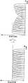
然而,即使是OFDM信号,因通过多径衰落而如图15所示那样特定频率的子载波的接收功率降低,没有得到期望的信号波对噪声功率比(Signal to Noise Power Ratio:以下称作“SNR”)的情况下,一部分的数据无法解调,从而作为系统的传输容量降低。However, even with OFDM signals, the received power of subcarriers of a specific frequency as shown in Fig. 15 is reduced due to multipath fading, and the desired Signal to Noise Power Ratio (Signal to Noise Power Ratio: hereinafter referred to as " SNR"), some data cannot be demodulated, and the transmission capacity of the system decreases.
为了解决这样课题,提出了下述方法:如图16所示,采用对于因多径衰落而接收功率的衰减大的子载波以多值数(multilevel)低的调制方式、对于接收功率的衰减小的子载波以多值数高的调制方式进行传输的自适应调制方式,并且采用调整传输数据的子载波的发送功率以使得到期望的SNR的多值发送功率控制方式(Multilevel Transmit Power Control:以下称作“MTPC”)的方法。该MTPC方式为从作为对多径衰落的对策、对发送功率的最大值等的限制、子载波的有效利用的角度来看受到注目的方式。In order to solve such a problem, a method has been proposed in which, as shown in FIG. 16 , a modulation scheme with a low multilevel is used for a subcarrier whose reception power is greatly attenuated due to multipath fading, and the attenuation of reception power is small. The subcarriers of the subcarriers are transmitted in an adaptive modulation method with a high multi-valued number, and the multilevel transmit power control method (Multilevel Transmit Power Control: the following called "MTPC"). The MTPC scheme is attracting attention from the viewpoints of countermeasures against multipath fading, restrictions on the maximum value of transmission power, etc., and efficient use of subcarriers.
图17是表示采用OFMD/MTPC方式的无线通信系统的帧格式的一结构例的图。该帧格式例如在建立从基站装置向移动台装置的下行链路(downlink)时使用。如图17所示,传输帧(通信帧)201由10个时隙202-1~202-10构成。此外,各时隙202-1~202-10从大的方面来分由同步/控制数据部203和用户数据部204这两个部分构成。FIG. 17 is a diagram showing an example of a frame format of a wireless communication system employing the OFMD/MTPC scheme. This frame format is used, for example, when establishing a downlink (downlink) from a base station device to a mobile station device. As shown in FIG. 17, a transmission frame (communication frame) 201 is composed of ten slots 202-1 to 202-10. In addition, each of the slots 202-1 to 202-10 is broadly divided into two parts: the synchronization/control data part 203 and the user data part 204.
同步/控制数据部203中包括在传输路径的推定中采用的接收侧已知的传输路径推定用数据串205(Channel Estimation word:以下称作“CE”)和用于向接收侧通知发送用户数据的各子载波的调制方式的调制方式信息206(Modulation Level Information:以下称作“MLI”)。它们用来定义各子载波的调制方式和各子载波的发送功率,成为OFDM/MTPC方式的特征。另外,MLI在每个通信帧中被更新。The synchronization/control data section 203 includes a transmission path estimation data string 205 (Channel Estimation word: hereinafter referred to as "CE") known to the receiving side and used for notifying the receiving side of the transmitted user data used in estimating the transmission path. Modulation Level Information 206 (Modulation Level Information: hereinafter referred to as "MLI") of the modulation scheme of each subcarrier. They are used to define the modulation mode of each sub-carrier and the transmission power of each sub-carrier, and become the characteristics of the OFDM/MTPC mode. Also, MLI is updated every communication frame.
在发送图17所示的帧格式的信号的情况下,就同步/控制数据部203而言以OFDM方式进行发送。即对于所有的子载波以相同的调制方式来统一,并且以相同发送功率进行发送。When transmitting a signal in the frame format shown in FIG. 17 , the synchronization/control data unit 203 performs transmission using the OFDM method. That is, all subcarriers are unified with the same modulation scheme and transmitted with the same transmission power.
此外,就用户数据部204而言以MTPC方式进行发送。即对每个子载波以调制多值数不同的调制方式进行发送,并且对每个子载波控制发送功率。具体来说,进行为如下。In addition, the user data unit 204 transmits by the MTPC method. That is, each subcarrier is transmitted using a modulation scheme with a different number of modulation values, and the transmission power is controlled for each subcarrier. Specifically, it proceeds as follows.
(1)每个子载波的调制方式为由同步/控制数据部的MLI所指定的调制方式。(1) The modulation scheme of each subcarrier is the modulation scheme designated by the MLI of the synchronization/control data section.
(2)根据传输路径的质量调整各子载波的发送功率,以使每个子载波在接收侧对得到期望的接收SNR。(2) Adjust the transmit power of each subcarrier according to the quality of the transmission path, so that each subcarrier can obtain a desired received SNR on the receiving side.
(3)也可对传输路径的质量极其不良的子载波不供给发送功率,而作为无载波信号区(carrier hole)。(3) The transmission power may not be supplied to a subcarrier whose quality of the transmission path is extremely poor, and may be used as a carrier hole.
在一般的通信中,由于相对于帧长度而言传输路径的变动速度缓慢,因此在同一帧内不需要改变发送功率、调制方式。从而,在同一通信帧内不需要改变发送功率和调制方式。因此,在同一通信帧内MLI都相同。In general communication, since the change speed of the transmission path is slow relative to the frame length, it is not necessary to change the transmission power and the modulation method within the same frame. Therefore, there is no need to change the transmission power and modulation method within the same communication frame. Therefore, the MLIs are all the same within the same communication frame.
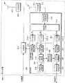
接下来,对适用于OFDM/MTPC通信系统中的移动台装置的结构例进行说明。如图18所示,移动台装置208具备接收电路209和发送电路210。接收天线211所接收的RF信号通过RF变换器(converter)212被降频变换后,输入到接收电路209。输入到接收电路209的RF变换器212的输出信号被输入到模拟/数字变换电路213,从模拟信号变换为数字信号。从模拟/数字变换电路213输出的数字信号被输入到多路信号分离器(demultiplexer)214,与图17所示的时隙的结构配合而分别分离输出到CE部205、MLI码元(symbol)部206和用户数据码元部204。Next, a configuration example of a mobile station apparatus applied to an OFDM/MTPC communication system will be described. As shown in FIG. 18 , the
傅立叶变换电路(FFT电路)215-1对多路信号分离器214的输出信号进行傅立叶变换而再生接收CE。传输路径推定电路216对从傅立叶变换电路215输出的接收CE和参考用CE进行比较,推定传输路径特性。A Fourier transform circuit (FFT circuit) 215-1 performs Fourier transform on the output signal of the
傅立叶变换电路(FFT电路)215-2对多路信号分离器214的输出信号进行傅立叶变换,再生接收MLI码元。传输路径补偿电路217根据传输路径推定电路216的推定结果对被再生的接收MLI码元进行传输路径补偿。码元解调电路218,从通过传输路径补偿电路217来被传输路径补偿的接收MLI码元中解调MLI。错误检测电路219,通过校验码对码元解调电路218的输出信号检测出错误等。A Fourier transform circuit (FFT circuit) 215-2 performs Fourier transform on the output signal of the
解调方式指定电路220基于被解调的MLI指定用户数据的各子载波的解调方式。The demodulation
傅立叶变换电路(FFT电路)215-3对多路信号分离器214的输出信号进行傅立叶变换,再生接收用户数据。传输路径补偿电路221基于传输路径推定电路216的推定结果对被再生的接收用户数据码元进行传输路径补偿。码元解调电路222以由解调方式指定电路220所指定的各子载波的用户数据码元部的解调方式来对由传输路径补偿电路221被实施过传输路径补偿的接收用户数据码元进行解调。解码电路223对由码元解调电路222所解调的编码用户数据进行纠错、解压处理,解码用户数据。A Fourier transform circuit (FFT circuit) 215-3 performs Fourier transform on the output signal of the
在图18所示的接收电路209中,对CE、MLI、用户数据进行解调的部分可总结为如下。In the
(1)由FFT电路215-1构成的CE解调部。(1) The CE demodulation unit constituted by the FFT circuit 215-1.
(2)由FFT电路215-2、传输路径补偿电路217、码元解调电路218和错误检测电路219构成的MLI解调部224。(2) The
(3)由FFT电路215-3、传输路径补偿电路221、码元解调电路222和解码电路223构成的用户数据解调部225。(3) User
此外,发送数据(用户数据)输入到发送电路210。发送电路210,对发送数据进行例如编码处理、调制处理、和将从传输路径推定电路216输入的传输路径推定结果信号作为信息数据向基站反馈的处理等。并且,进行数字/模拟变换,通过RF变换器226升频为RF信号后,通过发送天线227被发送。In addition, transmission data (user data) is input to the
接下来,对适用于OFDM/MTPC通信系统中的基站装置的结构例进行说明。如图19所示,基站装置230具备发送电路231和接收电路232。在发送电路231中,调制方式发送功率指定电路233基于由接收电路232作为接收数据所取得的传输路径推定结果信号,来决定用户数据(发送数据)发送时的各子载波的发送功率、用户数据发送时的各子载波的调制方式。Next, a configuration example of a base station apparatus applied to an OFDM/MTPC communication system will be described. As shown in FIG. 19 , the
编码电路234进行用户数据(发送数据)的压缩编码、纠错码的附加等的处理,码元调制电路235基于由调制方式发送功率指定电路233所决定的各子载波的调制方式,对用编码电路234来进行过编码的用户数据进行调制。发送功率控制电路236将码元调制电路235的输出信号调整为用调制方式发送功率指定电路233来对每个子载波所决定的值,IFFT电路237对发送功率控制电路236的输出信号进行傅立叶反变换并输出。The
MLI生成电路238基于由调制方式发送功率指定电路233所决定的用户数据发送时的各子载波的调制方式生成MLI。码元调制电路239对由MLI生成电路238所生成的MLI进行调制。IFFT电路240对码元调制电路239的输出信号进行傅立叶反变换并输出。The
CE生成电路241生成CE,IFFT电路242对由CE生成电路241所生成的CE进行傅立叶反变换后输出。The
多路复用器243对三个IFFT电路(237、240、242)的输出信号进行多路复用,以使成为如图17的时隙的结构。数字/模拟变换电路244将多路复用器243的输出从数字信号变换为模拟信号。从数字/模拟变换电路244所输出的模拟信号通过RF变换器245升频为RF信号后,通过发送天线246被发送。The
在图19所示的发送电路231中,对CE、MLI、用户数据进行调制的部分可总结为如下。In the
(1)由CE生成电路241和IFFT电路242构成的CE调制部247。(1) The CE modulator 247 composed of the
(2)由MLI生成电路238、码元调制电路239、IFFT电路240构成的MLI调制部248。(2) The
(3)由编码电路234、码元调制电路235、发送功率控制电路236和IFFT电路237构成的用户数据调制部249。(3) A user
此外,接收天线250所接收的RF信号通过RF变换器251被降频后,输入到接收电路232。接收电路232例如进行模拟/数字变换处理、对各种信号的分离处理、各种解调处理后,输出接收数据(用户数据)。In addition, the RF signal received by the receiving
非专利文献1:电子信息通信学会RCS2002-239“在一个蜂窝小区内重复采用了子载波自适应调制方式的OFDM/TDMA系统中的干扰降低技术相关的研究(Study on interference reducing technology in a one-cellrepetitive OFDM/TDMA system using a sub-carrier adaptive modulationsystem)”Non-Patent Document 1: RCS2002-239 of the Electronic Information and Communication Society "Study on interference reducing technology in a one- cellrepetitive OFDM/TDMA system using a sub-carrier adaptive modulation system)”
但是,在OFDM/MTPC方式中,在同一通信帧中存在的各时隙的MLI都相同。因此,如果在接收侧将MLI成功地解调一次,则该解调成功的MLI可使用于解调在同一通信帧中存在的所有的时隙中所包括的用户数据,而。反之,在接收侧成功解调MLI的情况下,可以说不需要之后接收的时隙中所包括的MLI。即如图20所示,例如在接收侧接收第一时隙时,MLI的解调成功的情况下,从之后的第二时隙到第N时隙中包括的MLI成为无用的数据。因此,发送侧继续发送无用的MLI,其结果使传输效率降低。However, in the OFDM/MTPC scheme, the MLI of each slot existing in the same communication frame is the same. Therefore, if the MLI is successfully demodulated once on the receiving side, the successfully demodulated MLI can be used to demodulate user data included in all slots existing in the same communication frame. Conversely, in the case where the receiving side successfully demodulates the MLI, it can be said that the MLI included in the slot received thereafter is unnecessary. That is, as shown in FIG. 20 , for example, when MLI demodulation succeeds when the receiving side receives the first slot, the MLI included in the subsequent second to Nth slots becomes useless data. Therefore, the transmitting side continues to transmit useless MLI, and as a result, the transmission efficiency decreases.
发明内容Contents of the invention
本发明正是鉴于上述问题而提出的,其目的在于提供一种通过阻止发送无用的MLI而能够提高传输效率的无线通信系统。The present invention has been made in view of the above problems, and an object of the present invention is to provide a wireless communication system capable of improving transmission efficiency by preventing transmission of useless MLI.
(1)为了达到上述目的,本发明采用以下方法。即本发明相关的调制器,是适用于采用由多个时隙构成的通信帧并以多载波调制方式进行无线通信的无线通信系统中的调制器,其特征在于,具备:时隙生成部,其对报头信息、调制方式信息和用户数据进行多路复用而生成上述时隙,其中上述报头信息至少包括用于推定传输路径的传输路径推定信息,上述调制方式信息用于向接收侧通知各子载波的调制方式;和判定部,其判定从接收侧是否接收了解调信息,该解调信息用于通知上述调制方式信息的解调已成功,在上述判定部判定为接收了上述解调信息的情况下,上述时隙生成部接收上述解调信息后,在该通信帧内生成不包括上述调制方式信息的时隙。(1) In order to achieve the above objects, the present invention adopts the following methods. That is, the modulator related to the present invention is a modulator suitable for use in a wireless communication system using a communication frame composed of a plurality of time slots and performing wireless communication in a multi-carrier modulation method, and is characterized in that it has: a time slot generation unit, It generates the time slot by multiplexing header information, modulation method information, and user data, wherein the header information includes at least transmission path estimation information for estimating a transmission path, and the modulation method information is used to notify the receiving side of each a modulation method of the subcarrier; and a determination unit that determines whether demodulation information for notifying that the demodulation of the modulation method information has been successful has been received from the receiving side, when the determination unit determines that the demodulation information has been received In the case of , after receiving the demodulation information, the time slot generation unit generates a time slot not including the modulation method information in the communication frame.
由此,在从接收侧接收了用于通知调制方式信息的解调成功的解调信息的情况下,接收解调信息后,在该通信帧内生成不包括调制方式信息的时隙,因此不会发送无用的调制方式信息。由此,由于时隙不会有无用的调制方式信息所占的时间,因此能够将该时间用于用户数据的传输中。例如通过除去时隙内无用的调制方式信息所占用的时间而缩短时隙长度,增加存在于同一通信帧内的时隙数,此外,能够不改变时隙长度而将无用的调制方式信息所占有的时间分配给用户数据。其结果能够实现传输效率的提高。Thus, when the demodulation information for notifying that the demodulation of the modulation method information has been successfully received from the receiving side is received, a time slot not including the modulation method information is generated in the communication frame after receiving the demodulation information. Useless modulation information is sent. Thereby, since there is no time occupied by useless modulation scheme information in the slot, the time can be used for the transmission of user data. For example, the time slot length can be shortened by removing the time occupied by useless modulation method information in the time slot, and the number of time slots existing in the same communication frame can be increased. In addition, useless modulation method information can be occupied without changing the time slot length. time allocated to user data. As a result, it is possible to improve transmission efficiency.
(2)此外,本发明相关调制器,其特征在于,在上述判定部判定为接收了上述解调信息的情况下,上述时隙生成部接收上述解调信息后,生成包括n个(n为自然数)的上述调制方式信息的时隙后,在该通信帧内生成不包括上述调制方式信息的时隙。(2) In addition, the correlated modulator of the present invention is characterized in that, when the determination unit determines that the demodulation information has been received, the slot generation unit generates n slots (where n is After the time slot of the above-mentioned modulation method information (natural number), a time slot not including the above-mentioned modulation method information is generated in the communication frame.
由此,接收解调信息后生成包括n个(n为自然数)的调制方式信息的时隙后,在该通信帧内生成不包括调制方式信息的时隙,因此时间上有空余而可进行负担少的处理。即,在发送电路中,接收解调信息以前开始进行时隙的发送处理,因此不易使接收解调信息之后的时隙不包括解调方式信息。从而,作为优选,将接收解调信息后的一定时间充当用于生成不包括调制方式信息的时隙的准备时间。此外,将接收解调信息后生成包括n个调制方式信息的时隙时所需的时间充当用于生成不包括调制方式信息的时隙的准备时间,因此可以以时隙为单位进行时间的管理。Thus, after receiving demodulation information and generating time slots including n (n is a natural number) modulation method information, time slots not including modulation method information are generated in the communication frame, so there is time vacancy and the burden can be less processing. That is, in the transmission circuit, since the transmission process of the slot is started before demodulation information is received, it is not easy to exclude demodulation method information from a slot after reception of demodulation information. Therefore, preferably, a certain time after receiving demodulation information is used as a preparation time for generating a slot that does not include modulation system information. In addition, since the time required to generate slots including n modulation method information after receiving demodulation information is used as preparation time for generating slots not including modulation method information, time management can be performed in units of slots .
(3)此外,本发明相关的调制器,是适用于采用由多个时隙构成的通信帧并以多载波调制方式进行无线通信的无线通信系统中的调制器,其特征在于,具备:时隙生成部,其对报头信息、调制方式信息和用户数据进行多路复用而生成上述时隙,其中上述报头信息至少包括用于推定传输路径的传输路径推定信息,上述调制方式信息用于向接收侧通知各子载波的调制方式;和时隙数信息生成部,其推定应包括上述调制方式信息的时隙的数目,生成用于向接收侧通知上述所推定的时隙的数目的时隙数信息,上述时隙生成部,对上述调制方式信息附加上述时隙数信息而生成上述所推定的数目的时隙后,在该通信帧内生成不包括上述调制方式信息的时隙。(3) In addition, the modulator related to the present invention is a modulator suitable for use in a wireless communication system using a communication frame composed of a plurality of time slots and performing wireless communication in a multi-carrier modulation method, and is characterized in that it has: a slot generation unit that multiplexes header information, modulation method information, and user data to generate the time slot, wherein the header information includes at least transmission path estimation information for estimating a transmission path, and the modulation method information is used to The receiving side notifies the modulation method of each subcarrier; and the number-of-slot information generation unit estimates the number of time slots that should include the above-mentioned modulation method information, and generates a time slot for notifying the receiving side of the estimated number of time slots The slot generation unit adds the slot number information to the modulation method information to generate the estimated number of slots, and then generates slots that do not include the modulation method information in the communication frame.
由此,推定应包括调制方式信息的时隙的数目,将时隙数信息附加给调制方式信息而生成推定的数目的时隙后,在该通信帧内生成不包括调制方式信息的时隙,因此不会发送无用的调制方式信息。由此,由于在时隙内不会有无用调制方式信息所占的时间,因此能够将该时间用于用户数据的传输。其结果,能够实现提高传输效率。此外,由于与调制方式信息一起发送包括调制方式信息的时隙的数目,因此发送侧的处理不会受到在接收侧调制方式信息的解调是否成功的影响,并且在发送侧不需要进行判定从接收侧是否已接收向发送侧通知调制方式信息的解调已成功的解调信息的处理,能够简化发送侧的处理。另一方面,接收侧如果成功解调调制方式信息和时隙数信息,则能够掌握包含有调制方式信息的时隙的数目。由此,接收侧成功解调调制方式信息和时隙数信息后,在接收了包括调制方式信息和时隙数信息的时隙的情况下,忽略调制方式信息,在接收了不包括调制方式信息的时隙的情况下,采用已解调的调制方式信息对用户数据进行解调。由此,不需要进行向发送侧通知调制方式信息的解调成功的处理,能够简化接收侧的处理。Thus, the number of time slots that should include the modulation method information is estimated, and the time slot number information is added to the modulation method information to generate the estimated number of time slots, and the time slots that do not include the modulation method information are generated in the communication frame, Therefore, useless modulation scheme information is not transmitted. Thereby, since there is no time occupied by useless modulation scheme information in the slot, the time can be used for transmission of user data. As a result, it is possible to improve transmission efficiency. In addition, since the number of slots including the modulation system information is transmitted together with the modulation system information, the processing on the transmission side is not affected by whether or not the demodulation of the modulation system information on the reception side is successful, and no judgment is required on the transmission side. Whether or not the reception side has received the demodulation information notifying the transmission side that demodulation of the modulation scheme information has succeeded can simplify the processing on the transmission side. On the other hand, if the receiving side successfully demodulates the modulation scheme information and the slot number information, it can grasp the number of slots including the modulation scheme information. Thus, after the receiving side successfully demodulates the modulation scheme information and the time slot number information, if it receives a time slot including the modulation scheme information and the time slot number information, it ignores the modulation scheme information; In the case of a time slot of , user data is demodulated using the demodulated modulation scheme information. Accordingly, it is not necessary to perform a process of notifying the transmission side that demodulation of the modulation scheme information has succeeded, and the processing on the reception side can be simplified.
(4)此外,本发明相关的调制器的特征在于,上述时隙数信息生成部,基于传输路径推定信息推定时隙数,该时隙数可得到为了解调上述调制方式信息而所需的信息功率。(4) Furthermore, the modulator according to the present invention is characterized in that the number-of-slots information generation unit estimates the number of slots based on the channel estimation information, and the number of slots can obtain the number of slots required for demodulation of the modulation method information. information power.
由此,基于传输路径推定信息推定可得到为了解调调制方式信息而所需的信号功率的时隙数,因此在接收侧可靠地进行调制方式信息的解调。此外,在发送侧不需要进行判定从接收侧是否已接收向发送侧通知调制方式信息的解调已成功的解调信息的处理,可简化发送侧的处理。Accordingly, since the number of slots at which the signal power required for demodulation of the modulation scheme information is obtained is estimated based on the channel estimation information, demodulation of the modulation scheme information is reliably performed on the reception side. In addition, the transmission side does not need to perform a process of judging whether demodulation information notifying the transmission side that demodulation of the modulation scheme information has been successfully received has been received from the reception side, and the processing on the transmission side can be simplified.
(5)此外,本发明相关的调制器的特征在于,上述时隙数信息是均表示同一数值的信息。(5) In addition, the modulator according to the present invention is characterized in that the information on the number of slots is information indicating the same numerical value.
由此,由于时隙数信息是均表示同一数值的信息,因此在接收侧通过对从通信帧的开头开始接收到的时隙的数目进行计数,能够掌握包括调制方式信息的时隙的数目,并且能够明确区别包括调制方式信息的时隙和不包括调制方式信息的时隙。Thus, since the number of slots information is information indicating the same value, the number of slots received from the head of the communication frame can be counted on the receiving side to grasp the number of slots including the modulation method information, And it is possible to clearly distinguish the time slots including the modulation mode information from the time slots not including the modulation mode information.
(6)此外,本发明相关的调制器的特征在于,上述时隙数信息是表示包括上述调制方式信息的时隙的剩余发送次数的信息。(6) In addition, the modulator according to the present invention is characterized in that the information on the number of slots is information indicating a remaining number of times of transmission of a slot including the modulation method information.
由此,由于时隙数信息为表示包括调制方式信息的时隙的剩余的发送次数的信息,因此对于在接受测中包括调制方式信息的任一个时隙,假设在接收侧接收电路无法检测出而遗漏时隙,即使在这种情况下也只要成功解调其他时隙中的调制方式信息和时隙数信息,则不会从该通信帧的开头开始计数所接收的时隙数,而之后发送几个包括调制方式信息的时隙,进而可掌握从哪个阶段开始发送不包括调制方式信息的时隙。由此,能够在接收侧避免错误地将不包括调制方式信息的时隙作为包括调制方式信息的时隙进行发送的情况。Thus, since the slot number information is information indicating the remaining number of times of transmission of the slot including the modulation method information, it is assumed that the receiving circuit on the receiving side cannot detect any slot including the modulation method information under test. And omission of time slots, even in this case, as long as the modulation information and time slot number information in other time slots are successfully demodulated, the number of received time slots will not be counted from the beginning of the communication frame, and after that By sending several time slots including modulation information, it is possible to know at which stage the time slots not including modulation information are sent. This prevents the receiving side from erroneously transmitting a slot that does not include modulation scheme information as a slot that includes modulation scheme information.
(7)此外,本发明相关的调制器的特征在于,上述时隙生成部,在生成不包括上述调制方式信息的时隙时,除去在上述时隙内分配给上述调制方式信息的时间而缩短时隙长度,缩短时隙长度的结果,根据上述通信帧内产生的空余时间,还生成不包括上述调制方式信息而时隙长度缩短的时隙。(7) In addition, the modulator according to the present invention is characterized in that, when generating a time slot not including the modulation method information, the time slot generating unit shortens the time allocated to the modulation method information in the time slot by removing the time slot. As a result of shortening the slot length, a slot having a shortened slot length is generated without including the modulation method information based on the vacant time generated in the above-mentioned communication frame.
由此,在生成不包括调制方式信息的时隙时,除去时隙内分配给调制方式信息的时间,缩短时隙长度,缩短时隙长度的结果为按照通信帧内产生的空余时间,还生成不包括调制方式信息而时隙长度缩短的时隙,因此与以往相比,可增加在具有同一时间长度的通信帧内可存在的时隙数。由此,由于能够更多地传输用户数据,因此能够实现传输效率的提高。Thus, when generating a time slot that does not include the modulation method information, the time allocated to the modulation method information in the time slot is removed, and the length of the time slot is shortened. The result of shortening the length of the time slot is that according to the vacant time generated in the communication frame, a time slot is also generated. Since the slot length is shortened without including modulation system information, the number of slots that can exist in a communication frame having the same time length can be increased compared to conventional ones. Thereby, since more user data can be transmitted, it is possible to improve transmission efficiency.
(8)此外,本发明相关的调制器的特征在于,上述时隙生成部,通过将在上述时隙内分配给上述调制方式信息的时间分配给上述用户数据来代替上述调制方式信息,从而以不改变时隙长度的方式生成不包括上述调制方式信息的时隙。(8) In addition, the modulator according to the present invention is characterized in that the time slot generation unit allocates time allocated to the modulation method information in the time slot to the user data instead of the modulation method information, thereby using A slot that does not include the above-mentioned modulation scheme information is generated without changing the slot length.
由此,通过将在时隙内分配给调制方式信息的时间分配给用户数据来代替调制方式信息,不改变时隙长度而生成不包括调制方式信息的时隙,因此与以往相比可增加具有同一时间长度的时隙内的用户数据所占的比例。由此,可更多地传输用户数据,因此可提高传输效率。本发明适用于例如TDMA(Time Division Multiple Access:时分多址)那样时隙长度必须恒定的系统中。Thus, by allocating the time allocated to the modulation method information in the slot to user data instead of the modulation method information, a slot that does not include the modulation method information is generated without changing the slot length, so that it is possible to increase The proportion of user data in a time slot of the same time length. As a result, more user data can be transmitted, and thus transmission efficiency can be improved. The present invention is applicable to systems such as TDMA (Time Division Multiple Access: Time Division Multiple Access) where the time slot length must be constant.
(9)此外,本发明相关的解调器,是适用于采用由多个时隙构成的通信帧并以多载波调制方式进行无线通信的无线通信系统中的解调器,上述多个时隙包括用于向接收侧通知至少各子载波的调制方式的调制方式信息、和用户数据,其特征在于,具备:调制方式信息解调部,其从在发送侧的本发明之一上述的调制器中生成而通过无线方式所接收的时隙中的时隙中抽出上述调制方式信息,对上述所抽出的调制方式信息进行解调;解调信息生成部,其判定上述调制方式信息的解调是否成功,在上述解调成功的情况下,生成用于对发送侧通知上述调制方式信息的解调已成功的解调信息;和用户数据解调部,其在生成上述解调信息后,为了对相当于在同一通信帧中存在的各时隙内的上述用户数据的各子载波进行解调,而使用上述解调已成功的解调方式信息。(9) In addition, the demodulator related to the present invention is a demodulator suitable for use in a wireless communication system using a communication frame composed of a plurality of time slots and performing wireless communication in a multi-carrier modulation method. Including modulation scheme information for notifying the modulation scheme of at least each subcarrier to the receiving side, and user data, characterized in that: a modulation scheme information demodulation unit is provided from the above-mentioned modulator according to one of the present inventions on the transmitting side Extract the above-mentioned modulation method information from the time slots of the time slots generated in the wireless method and received by the wireless method, and demodulate the above-mentioned extracted modulation method information; the demodulation information generation unit determines whether the demodulation of the above-mentioned modulation method information Success, when the demodulation is successful, generating demodulation information for notifying the transmitting side that the demodulation of the modulation method information has succeeded; and a user data demodulation unit, after generating the demodulation information, in order to Each subcarrier corresponding to the user data in each slot existing in the same communication frame is demodulated, and the demodulation method information that the demodulation has been successful is used.
由此,在成功解调调制方式信息的情况下,生成用于对发送侧通知调制方式信息的解调成功的解调信息,生成解调信息后,为了对相当于存在于同一通信帧中的各时隙内的用户数据的各子载波进行解调,使用上述已成功解调的调制方式信息,因此在调制方式信息的解调成功后,在接收侧中调制方式信息成为无用信息。并且,通过将解调信息发送到发送侧,在发送侧接收解调信息后,能够生成不包括调制方式信息的时隙。由此,不发送无用的调制方式信息,能够实现传输效率的提高。Thus, when the modulation method information is successfully demodulated, demodulation information for notifying the transmitting side that the demodulation of the modulation method information is successful is generated, and after the demodulation information is generated, in order to Each subcarrier of user data in each slot is demodulated, and the above-mentioned successfully demodulated modulation scheme information is used. Therefore, after the demodulation of the modulation scheme information is successful, the modulation scheme information becomes useless information on the receiving side. Also, by transmitting the demodulation information to the transmission side, the transmission side can generate a slot that does not include modulation scheme information after receiving the demodulation information. As a result, useless modulation scheme information is not transmitted, and transmission efficiency can be improved.
(10)此外,本发明相关的解调器,是适用于采用由多个时隙构成的通信帧并以多载波调制方式进行无线通信的无线通信系统中的解调器,上述多个时隙包括用于向接收侧通知至少各子载波的调制方式的调制方式信息和用户数据,特征在于,具备:抽出部,其从所接收的时隙中抽出上述调制方式信息、和附加在上述调制方式信息上的时隙数信息,其中上述时隙数信息表示在同一上述通信帧内存在的包括上述调制方式信息的时隙的数目;调制方式/时隙数信息解调部,其对上述所抽出的调制方式信息和时隙数信息进行解调;和用户数据解调部,其判定上述调制方式信息和时隙数信息的解调是否成功,在上述解调已成功的情况下,抽出上述时隙数,并基于所抽出的时隙数特定包括上述调制方式信息和时隙数信息的最后的时隙,为了对相当于在上述特定的时隙的下一个时隙以后、存在于同一个通信帧中的各时隙内的上述用户数据的各子载波进行解调,而使用上述解调已成功的上述调制方式信息。(10) In addition, the demodulator related to the present invention is a demodulator suitable for use in a wireless communication system using a communication frame composed of a plurality of time slots and performing wireless communication in a multi-carrier modulation method. It includes modulation scheme information and user data for notifying the modulation scheme of at least each subcarrier to the receiving side, and is characterized in that an extracting unit is provided for extracting the modulation scheme information from the received time slot, and adding the modulation scheme information to the modulation scheme information on the number of time slots on the information, wherein the number of time slots information indicates the number of time slots including the information on the modulation method existing in the same communication frame; demodulation of the modulation method information and slot number information; and a user data demodulation unit that determines whether the demodulation of the modulation method information and the slot number information is successful, and extracts the time slot if the demodulation is successful. number of slots, and based on the extracted number of slots, specify the last time slot including the above-mentioned modulation method information and the number of time slots information, in order to correspond to the same communication that exists after the next time slot of the above-mentioned specific time slot Each subcarrier of the user data in each time slot in the frame is demodulated, and the modulation method information that the demodulation has been successful is used.
由此,从接收的时隙抽出调制方式信息和时隙数信息,该调制方式信息和时隙数信息解调成功的情况下抽出时隙数,基于抽出的时隙数特定包括调制方式信息和时隙数信息的最后时隙,因此能够明确区别包括调制方式信息和时隙数信息的时隙和不包括的时隙。此外,上述特定的时隙的下一个时隙以后,为了对相当于在同一通信帧内存在的各时隙的用户数据的各子载波进行解调,而使用上述解调成功的调制方式信息,因此在调制方式信息和时隙数信息的解调成功后,在接收侧中调制方式信息成为无用信号。并且,在发送侧将时隙数信息附加给调制方式信息而生成所推定的数目的时隙后,在该通信帧内生成不包括调制方式信息的时隙,因此不会发送无用的调制方式信息。由此,由于在时隙内不会有无用的调试方式信息所占的时间,因此能够将该时间用于用户数据的传输。其结果,可提高传输效率。Thus, the modulation method information and the slot number information are extracted from the received slots, and when the demodulation of the modulation method information and the slot number information is successful, the slot number is extracted, and the modulation method information and the slot number are specified based on the extracted slot number. Therefore, it is possible to clearly distinguish between slots including modulation scheme information and slot number information and slots not included. In addition, in order to demodulate each subcarrier corresponding to the user data of each slot existing in the same communication frame after the slot next to the above-mentioned specific slot, the modulation method information for which the demodulation was successful is used, Therefore, after demodulation of the modulation scheme information and the slot number information is successful, the modulation scheme information becomes an unnecessary signal on the receiving side. In addition, since the transmission side adds slot number information to the modulation method information to generate an estimated number of time slots, a time slot not including the modulation method information is generated in the communication frame, so useless modulation method information is not transmitted. . As a result, since there is no time occupied by useless debugging mode information in the time slot, the time can be used for transmission of user data. As a result, transmission efficiency can be improved.
(11)此外,本发明相关的基站装置的特征在于包括上述任一项上述的调制器,(12)此外,本发明相关的移动台装置的特征在于包括上述任一项上述的解调器。(13)此外,本发明相关的无线通信系统的特征在于,由上述基站装置和移动台装置构成。(11) In addition, the base station apparatus according to the present invention is characterized by including any one of the above-mentioned modulators, and (12) In addition, the mobile station apparatus according to the present invention is characterized by including any one of the above-mentioned demodulators. (13) In addition, a wireless communication system according to the present invention is characterized by comprising the above-mentioned base station device and mobile station device.
根据该结构,由于不会发送无用的调制方式信息,因此在时隙内不会有无用的调制方式信息所占的时间,可将该时间用于用户数据的传输中。其结果可提高传输效率。According to this configuration, since useless modulation method information is not transmitted, there is no time occupied by useless modulation method information in the slot, and this time can be used for user data transmission. As a result, transmission efficiency can be improved.
(发明效果)(invention effect)
通过本发明,由于不会发送无用的调制方式信息,因此在时隙内不会有无用的调制方式信息所占的时间,可将该时间用于用户数据的传输中。结果可提高传输效率。Through the present invention, since useless modulation information is not sent, there is no time occupied by useless modulation information in the time slot, and the time can be used for user data transmission. As a result, transfer efficiency can be improved.
附图说明Description of drawings
图1为表示第一实施方式相关的无线通信系统的概要的图。FIG. 1 is a diagram showing an overview of a wireless communication system according to a first embodiment.
图2为表示第一实施方式相关的无线通信系统的基站装置和移动台装置之间的传输顺序的图。2 is a diagram showing a transmission sequence between a base station device and a mobile station device in the wireless communication system according to the first embodiment.
图3为表示第一实施方式相关的移动台装置的结构的框图。Fig. 3 is a block diagram showing the configuration of a mobile station device according to the first embodiment.
图4为表示第一实施方式相关的基站装置的结构的框图。FIG. 4 is a block diagram showing the configuration of a base station apparatus according to the first embodiment.
图5为表示第一实施方式相关的移动台装置的动作的流程图。Fig. 5 is a flowchart showing the operation of the mobile station device according to the first embodiment.
图6为表示第一实施方式相关的基站装置的动作的流程图。FIG. 6 is a flowchart showing the operation of the base station apparatus according to the first embodiment.
图7为表示第二实施方式相关的无线通信系统的基站装置和移动台装置之间的数据传输顺序的图。7 is a diagram showing a data transmission sequence between a base station device and a mobile station device in a radio communication system according to the second embodiment.
图8为表示第三实施方式相关的移动台装置的结构的框图。Fig. 8 is a block diagram showing the configuration of a mobile station device according to the third embodiment.
图9为表示矢量相加电路的矢量相加处理的流程图。FIG. 9 is a flowchart showing vector addition processing by the vector addition circuit.
图10为表示第三实施方式相关的基站装置的结构的框图。FIG. 10 is a block diagram showing the configuration of a base station apparatus according to the third embodiment.
图11为表示第三实施方式相关的移动台装置的动作的流程图。Fig. 11 is a flowchart showing the operation of the mobile station device according to the third embodiment.
图12为表示第三实施方式相关的基站装置的动作的流程图。Fig. 12 is a flowchart showing the operation of the base station apparatus according to the third embodiment.
图13为表示第四实施方式相关的无线通信系统的帧格式的一结构例的图。Fig. 13 is a diagram showing an example of a frame format of a wireless communication system according to the fourth embodiment.
图14为表示第五实施方式相关的无线通信系统的帧格式的一结构例的图。Fig. 14 is a diagram showing an example of a frame format of a radio communication system according to a fifth embodiment.
图15为表示正交频分复用系统的矢量的图。Fig. 15 is a diagram showing vectors of an OFDM system.
图16为表示采用多值发送功率控制方式的正交频分复用系统的矢量的图。Fig. 16 is a diagram showing vectors of an OFDM system employing a multilevel transmission power control method.
图17为表示采用多值发送功率控制方式的正交频分复用系统的帧格式的图。Fig. 17 is a diagram showing a frame format of an OFDM system employing a multilevel transmission power control method.
图18为表示适用于OFDM/MTPC通信系统中的移动台装置的结构例的框图。Fig. 18 is a block diagram showing a configuration example of a mobile station apparatus applied to the OFDM/MTPC communication system.
图19为表示适用于OFDM/MTPC通信系统中的基站装置的结构例的框图。Fig. 19 is a block diagram showing a configuration example of a base station apparatus applied to an OFDM/MTPC communication system.
图20为表示MLI的解调成功后的时隙的状态的图。FIG. 20 is a diagram showing the status of slots after MLI demodulation is successful.
图中:In the picture:
103-接收动作控制电路;113-发送动作控制电路;123-矢量相加电路;124-存储电路;125-切换电路;126-MLI发送时隙数抽出电路;128-MLI接收控制电路;133-MLI发送时隙数推定电路;134-发送动作控制电路。103-receiving action control circuit; 113-sending action control circuit; 123-vector addition circuit; 124-storage circuit; 125-switching circuit; 126-MLI sending time slot number extraction circuit; 128-MLI receiving control circuit; 133- MLI transmission slot number estimation circuit; 134 - transmission action control circuit.
具体实施方式Detailed ways
(第一实施方式)(first embodiment)
图1是表示第一实施方式相关的无线通信系统的概要的图。基站装置1,与在小区(cell)2内存在的移动台装置3之间通过频分双工(FDD:Frequency Division Duplex)进行双向通信。从基站装置1向移动台装置3的发送(下行链路)采用频率f1,以MTPC方式进行。此外,从移动台装置3向基站装置1的发送(上行链路)采用频率f2。对于上行链路的通信方式或帧格式没有特别限定,能够采用以往公知的通信方式和帧格式。FIG. 1 is a diagram showing an overview of a radio communication system according to a first embodiment. A base station device 1 performs bidirectional communication with a
第一实施方式相关的无线通信系统中,如果作为接收侧的移动台装置成功解调MLI,则作为发送侧的基站装置中止发送MLI。为了实现该动作,在该无线通信系统中,移动台装置成功解调MLI的情况下,向基站装置发送表示作为成功于该解调的解调信息的ACK(ACKnowledgement),以后设为同一通信帧中存在的时隙内没有MLI,而对用户数据进行解调。此外,在对用户数据进行解调时,使用已经解调成功的MLI。参照图2对这些的概要进行说明。In the wireless communication system according to the first embodiment, when the mobile station device on the receiving side successfully demodulates the MLI, the base station device on the transmitting side stops transmitting the MLI. In order to realize this operation, in this wireless communication system, when the mobile station apparatus successfully demodulates the MLI, it transmits ACK (ACKnowledgment) indicating that the demodulation has succeeded in the demodulation to the base station apparatus, and sets it as the same communication frame There is no MLI in the time slots existing in , and the user data is demodulated. In addition, when demodulating user data, the MLI that has been successfully demodulated is used. An overview of these will be described with reference to FIG. 2 .
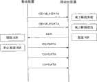
图2为表示第一实施方式相关的无线通信系统中的基站装置和移动台装置之间的数据传输顺序的图。图2中,从纸面的上方向下方设为时间经过的方向。基站装置对移动台装置发送包括CE、MLI和用户数据的第一时隙。移动台装置中,对第一时隙MLI的解调失败时,基站装置未接收到ACK,因此第二时隙中也包括CE、MLI和用户数据而进行发送。2 is a diagram showing a data transmission sequence between a base station device and a mobile station device in the wireless communication system according to the first embodiment. In FIG. 2 , the direction of time elapses from the top to the bottom of the sheet. The base station apparatus transmits the first slot including CE, MLI, and user data to the mobile station apparatus. In the mobile station apparatus, when demodulation of MLI in the first slot fails, the base station apparatus does not receive ACK, and therefore transmits CE, MLI, and user data in the second slot as well.
接下来,移动台装置中,对于第二时隙成功解调MLI。因此,移动台装置发送对基站装置发送通知MLI的解调成功的ACK。基站装置接收到ACK后,在下一个通信帧之前不需要发送MLI,因此中止MLI的发送。即该通信帧内,对移动台装置发送不包括MLI的时隙。移动台装置,对于发送ACK后所接收的时隙,作为没有MLI而只包括CE和用户数据的时隙来接收后,进行用户数据的解调。接下来,对发挥这种功能的移动台装置和基站装置的结构进行说明。Next, the mobile station device successfully demodulates the MLI for the second slot. Therefore, the mobile station device transmits an ACK notifying the base station device that demodulation of the MLI has succeeded. After receiving the ACK, the base station apparatus does not need to transmit the MLI until the next communication frame, so the transmission of the MLI is suspended. That is, within this communication frame, a slot that does not include the MLI is transmitted to the mobile station device. The mobile station apparatus demodulates the user data after receiving the received slots after transmission of the ACK as slots including only the CE and user data without the MLI. Next, configurations of a mobile station device and a base station device that perform such functions will be described.
图3是表示第一实施方式的相关移动台装置的结构的框图。对发挥与图18中所示的现有的移动台装置相同的功能的模块赋予相同的符号并进行说明。如图3所示,移动台装置100具备接收电路101和发送电路102。接收天线211所接收的RF信号通过RF变换器212被降频后,输入到接收电路101。输入到接收电路101的RF变换器212的输出信号输入到模拟/数字变换电路213,而从模拟信号变换为数字信号。从模拟/数字变换电路213所输出的数字信号输入到多路信号分离器214后,与图17所示的时隙的结构配合而分别分离输出到CE部205、MLI码元部206和用户数据码元部204。Fig. 3 is a block diagram showing the configuration of a related mobile station device according to the first embodiment. Modules that perform the same functions as those of the conventional mobile station device shown in FIG. 18 will be described with the same reference numerals. As shown in FIG. 3 , the mobile station device 100 includes a reception circuit 101 and a transmission circuit 102 . The RF signal received by the receiving
傅立叶变换电路(FFT电路)215-1对多路信号分离器214的输出信号进行傅立叶变换,再生接收CE。传输路径推定电路216对从傅立叶变换电路215-1输入的接收CE和参考用CE进行比较,推定传输路径特性。A Fourier transform circuit (FFT circuit) 215-1 performs Fourier transform on the output signal of the
傅立叶变换电路(FFT电路)215-2对多路信号分离器214的输出信号进行傅立叶变换,再生接收MLI码元。传输路径补偿电路217对被再生的接收MLI码元基于传输路径推定电路216的推定结果进行传输路径补偿。码元解调电路218,从通过传输路径补偿电路217被传输路径补偿的接收MLI码元解调出MLI。A Fourier transform circuit (FFT circuit) 215-2 performs Fourier transform on the output signal of the
错误检测电路219通过校验码对码元解调电路218的输出信号检测出错误等。并且,错误检测电路219在码元解调电路218的输出信号中未检测出错误的情况下,向发送电路102和接收动作控制电路103输出请求发送ACK的信号,其中ACK作为表示MLI的解调成功的解调信息。The
解调方式指定电路220基于被解调的MLI指定用户数据的各子载波的解调方式。The demodulation
傅立叶变换电路(FFT电路)215-3对多路信号分离器214的输出信号进行傅立叶变换,而再生接收用户数据。传输路径补偿电路221基于传输路径推定电路216的推定结果对被再生的接收用户数据码元进行传输路径补偿。码元解调电路222,以由解调方式指定电路220所指定的各子载波的用户数据码元部的解调方式,对由传输路径补偿电路221实施传输路径补偿的接收用户数据码元进行解调。解码电路223对由码元解调电路222所解调的编码用户数据进行纠错、解压处理,解码用户数据。A Fourier transform circuit (FFT circuit) 215-3 performs Fourier transform on the output signal of the
在图3所示的接收电路101中,对CE、MLI、用户数据进行解调的部分可总结为如下。In the receiving circuit 101 shown in FIG. 3 , the part that demodulates CE, MLI, and user data can be summarized as follows.
(1)由FFT电路215-1构成的CE解调部。(1) The CE demodulation unit constituted by the FFT circuit 215-1.
(2)由FFT电路215-2、传输路径补偿电路217、码元解调电路218和错误检测电路219构成的MLI解调部224。(2) The
(3)由FFT电路215-3、传输路径补偿电路221、码元解调电路222和解码电路223构成的用户数据解调部225。(3) User
此外,接收动作控制电路103基于请求发送从错误检测电路219所输入的ACK的信号,控制MLI解调部224、用户数据解调部225和多路信号分离器214的动作,以使接收不包括MLI的时隙。Furthermore, reception operation control circuit 103 controls the operations of
在移动台装置100中,发送数据(用户数据)被输入到发送电路102。发送电路102对发送数据进行例如编码处理、调制处理、和将从传输路径推定电路216输入的传输路径推定结果信号作为信息数据对基站进行反馈的处理等。并且,被实施数字/模拟变换,通过RF变换器226升频为RF信号后,通过发送天线227被发送。In mobile station device 100 , transmission data (user data) is input to transmission circuit 102 . The transmission circuit 102 performs, for example, encoding processing, modulation processing, and processing of feeding back a channel estimation result signal input from the
进一步,发送电路102接收请求发送ACK的信号后,生成ACK信号并进行发送。Further, the transmission circuit 102 generates and transmits an ACK signal after receiving a signal requesting transmission of an ACK.
接下来,参照图4对第一实施方式相关的基站装置的结构进行说明。对实现与图19所示的现有的基站装置相同的功能的模块赋予相同的符号,并进行说明。如图4所示,基站装置110具备发送电路111和接收电路112。发送电路111中,调制方式发送功率指定电路233基于由接收电路112作为接收数据来所取得的传输路径推定结果信号决定用户数据(发送数据)发送时的各子载波的发送功率、用户数据发送时的各子载波的调制方式。编码电路234进行用户数据(发送数据)的压缩编码、纠错码的附加等的处理,码元调制电路235基于由调制方式发送功率指定电路233所决定的各子载波的调制方式,对用编码电路234进行过编码的用户数据进行调制。发送功率控制电路236将编码调制电路235的输出信号调整为对每个子载波由调制方式发送功率指定电路233所决定的值,IFFT电路237对发送功率控制电路236的输出信号进行傅立叶反变换并输出。Next, the configuration of the base station apparatus according to the first embodiment will be described with reference to FIG. 4 . Blocks that realize the same functions as those of the conventional base station apparatus shown in FIG. 19 are assigned the same symbols and described. As shown in FIG. 4 , the base station apparatus 110 includes a
MLI生成电路238基于由调制方式发送功率指定电路233所决定的用户数据发送时的各子载波的调制方式生成MLI。码元调制电路239对由MLI生成电路238所生成的MLI进行调制。IFFT电路240对码元调制电路239的输出信号进行傅立叶反变换并输出。The
CE生成电路241生成CE,IFFT电路242对由CE生成电路241所生成的CE进行傅立叶反变换后输出。The
在图4所示的发送电路111中,对CE、MLI、用户数据进行调制的部分总结为如下。In the
(1)由CE生成电路241和IFFT电路242构成的CE调制部247。(1) The CE modulator 247 composed of the
(2)由MLI生成电路238、码元调制电路239、IFFT电路240构成的MLI调制部248。(2) The
(3)由编码电路234、码元调制电路235、发送功率控制电路236和IFFT电路237构成的用户数据调制部249。(3) A user
多路复用器243对三个IFFT电路(237、240、242)的输出信号进行多路复用,以使成为图17的时隙的结构。The
发送动作控制电路113基于通知已接收从接收电路112所输入的ACK的信号,对MLI调制部248、用户数据调制部249和多路复用器243的动作时序(timing)进行控制以使生成不包括MLI的时隙。The transmission operation control circuit 113 controls the operation timing (timing) of the
数字/模拟变换电路244将多路复用器243的输出从数字信号变换为模拟信号。从数字/模拟变换电路244所输出的模拟信号通过RF变换器245升频为RF信号后,通过发送天线246被发送。The digital/
此外,接收天线250所接收的RF信号通过RF变换器251被降频后,输入到接收电路112。接收电路112进行例如模拟/数字变换处理、对各种信号的分离处理、和各种解调处理,从而输出接收数据(用户数据)。此外,在接收电路112中,对接收天线250所接收的RF信号中所包括的ACK进行解调,向发送电路111中的发送动作控制电路113输出。进一步,接收电路132基于接收信号推定传输路径的状况,向发送电路131输出推定结果信号。In addition, the RF signal received by the receiving
接下来,参照图5所示的流程图,对有关如上所述那样构成的第一实施方式的移动台装置的动作进行说明。移动台装置100中,接收电路101接收包括CE、MLI和用户数据的时隙后(步骤S1),在MLI解调部224中对MLI进行解调(步骤S2)。在MLI中,包括校验位等,判定MLI解调部224中的错误检测电路219是否成功解调MLI,即是否检测出错误(步骤S3)。在MLI的解调失败的情况下,即检测出误差的情况下,转移到步骤S1,再次进入接收下一个时隙的状态。Next, the operation of the mobile station apparatus according to the first embodiment configured as described above will be described with reference to the flowchart shown in FIG. 5 . In the mobile station device 100, after the receiving circuit 101 receives a slot including CE, MLI, and user data (step S1), the
另一方面,在步骤S3中,在MLI的解调成功的情况下,即没有检测出错误的情况下,错误检测电路219向发送电路102和接收动作控制电路103输出请求发送ACK的信号,该ACK用于对基站装置通知MLI的解调已成功。发送电路102对基站装置发送ACK(步骤S4),接收动作控制电路103基于请求发送ACK的信号,控制MLI解调部224、用户数据解调部225和多路信号分离器214的动作,以使接收不包括MLI的时隙。On the other hand, in step S3, when the MLI demodulation is successful, that is, when no error is detected, the
并且,在步骤S2中基于已解调的MLI对用户数据进行解调(步骤S5),判断该通信帧是否结束(步骤S6)。在该通信帧没有结束的情况下,接收从基站装置依次发送过来的不包括MLI的时隙,也就是包括CE和用户数据的时隙(步骤S7),使用在步骤S2中已解调的MLI而在步骤S7中对接收的用户数据进行解调(步骤S5)。在该通信帧结束之前重复进行从步骤S5到步骤S7的动作。即从MLI的解调成功后到该通信帧结束之前的期间,设为接收时隙中只包括CE和用户数据而进行解调。在步骤S6中,在该通信帧结束的情况下,转移到步骤S1,设为从下一个通信帧开始再次发送过来包括MLI的时隙,而进行接收。And, in step S2, the user data is demodulated based on the demodulated MLI (step S5), and it is judged whether the communication frame ends (step S6). If the communication frame has not ended, receive the time slots that do not include the MLI, that is, the time slots that include CE and user data sequentially transmitted from the base station apparatus (step S7), and use the demodulated MLI in step S2 In step S7, however, the received user data is demodulated (step S5). The operations from step S5 to step S7 are repeated until the communication frame ends. That is, during the period from the successful demodulation of the MLI to the end of the communication frame, demodulation is performed assuming that only CE and user data are included in the reception slot. In step S6, when this communication frame ends, it transfers to step S1, and assumes that the time slot including MLI is transmitted again from the next communication frame, and is received.
接下来,参照图6所示的流程图对第一实施方式相关的基站装置的动作进行说明。在基站装置110中,发送电路111决定调制方式和发送功率(步骤T1)。即在MTPC方式中,基站装置110以通过来自移动台装置100的反馈等,掌握传输路径推定结果为前提。发送电路111基于传输路径推定结果决定每个子载波的调制方式和发送功率,以使得到移动台装置100所需要的SNR。此外,与此同时,决定MLI生成电路238所生成的MLI(步骤T2)。接下来,发送包括CE、上述已决定的MLI和用户数据的时隙(步骤T3),判断该通信帧是否结束(步骤T4)。Next, the operation of the base station apparatus according to the first embodiment will be described with reference to the flowchart shown in FIG. 6 . In the base station apparatus 110, the
在该通信帧结束的情况下,转移到步骤T1,在该通信帧没有结束的情况下,判断是否已接收ACK(步骤T5)。在未接收到ACK的情况下,转移到步骤T3,再次发送包括CE、MLI和用户数据的时隙。另一方面,在步骤T5中,在接收到ACK的情况下,发送不包括MLI的时隙、即包括CE和用户数据的时隙(步骤T6)。接下来,判断该通信帧是否结束(步骤T7),在没有结束的情况下,转移到步骤T6,直到该通信帧结束为止重复进行步骤T6和步骤T7的动作。另一方面,在步骤T6中,该通信帧结束的情况下,转移到步骤T1,再次基于传输路径推定结果决定MLI,开始发送包括MLI的时隙。When the communication frame ends, the process moves to step T1, and if the communication frame does not end, it is judged whether or not ACK has been received (step T5). If ACK is not received, transfer to step T3, and retransmit the time slot including CE, MLI and user data. On the other hand, in step T5, when ACK is received, a slot not including MLI, that is, a slot including CE and user data is transmitted (step T6). Next, it is judged whether the communication frame is finished (step T7), if not finished, transfer to step T6, and the operations of step T6 and step T7 are repeated until the communication frame ends. On the other hand, in step T6, when the communication frame ends, the process proceeds to step T1, where the MLI is determined again based on the channel estimation result, and the transmission of the slot including the MLI is started.
如上所述,通过第一实施方式相关的无线通信系统,不会发送无用的MLI,因此在时隙内不会有无用的MLI所占的时间,能够将该时间使用于用户数据的传输。其结果可实现传输效率的提高。As described above, the wireless communication system according to the first embodiment does not transmit useless MLI, so there is no time occupied by useless MLI in a slot, and the time can be used for user data transmission. As a result, the improvement of transmission efficiency can be aimed at.
(第二实施方式)(second embodiment)
接下来,对第二实施方式相关的无线通信系统进行说明。图7为表示第二实施方式相关的无线通信系统中的基站装置和移动台装置之间的数据传输顺序的图。图7中与图2相同,从纸面的上方向下方为时间经过的方向。基站装置对移动台装置发送包括CE、MLI和用户数据的第一时隙。移动台装置中,对第一时隙MLI的解调失败时,基站装置不接收ACK,因此第二时隙内也包括CE、MLI和用户数据而进行发送。Next, a radio communication system related to the second embodiment will be described. 7 is a diagram showing a data transmission sequence between a base station device and a mobile station device in a radio communication system according to the second embodiment. In FIG. 7 , as in FIG. 2 , the direction of time elapses from the top to the bottom of the page. The base station apparatus transmits the first slot including CE, MLI, and user data to the mobile station apparatus. In the mobile station apparatus, when the demodulation of the MLI in the first slot fails, the base station apparatus does not receive the ACK, and therefore transmits CE, MLI, and user data in the second slot as well.
接下来,移动台装置,在第二时隙中成功解调MLI。因此,移动台装置对基站装置发送通知MLI的解调成功的ACK。基站装置接收ACK后,在下一个通信帧之前不需要发送MLI,因此中止MLI的发送。即该通信帧内,对移动台装置发送不包括MLI的时隙。Next, the mobile station successfully demodulates the MLI in the second slot. Therefore, the mobile station apparatus transmits ACK notifying that the demodulation of the MLI has succeeded, to the base station apparatus. After receiving the ACK, the base station apparatus does not need to transmit the MLI until the next communication frame, so the transmission of the MLI is suspended. That is, within this communication frame, a slot that does not include the MLI is transmitted to the mobile station device.
在此,第二实施方式中,基站装置接收到ACK后,例如发送一个时隙后,发送不包括MLI的时隙。这是因为,在基站装置中,在接收到ACK时已经开始进行用于发送下一个时隙的处理,因此在接收到ACK之后紧接着的时隙开始不易中止MLI的发送。Here, in the second embodiment, after receiving the ACK, for example, after transmitting one slot, the base station apparatus transmits a slot that does not include the MLI. This is because the base station apparatus has already started processing for transmitting the next slot when ACK is received, and therefore it is difficult to suspend MLI transmission from the slot immediately after receiving ACK.
如图7所示,移动台装置,由于在第二时隙中成功解调MLI,因此对基站装置发送ACK。基站装置中,在接收到ACK时开始进行在第三时隙中包括MLI而发送的处理,因此直接发送包括MLI的时隙。并且,对第四时隙而言,生成不包括MLI的时隙而进行发送。移动台装置,将第三时隙设为不包括MLI的时隙而进行接收,第四时隙以后到该通信帧结束之前所接收的时隙设为没有MLI、只包括CE和用户数据的时隙而进行接收,进行用户数据的解调。另外,在图7中,对在基站装置中接收ACK后到从一个时隙后发送不包括MLI的时隙的情况进行说明,但本发明并不限定于此。例如也可在基站装置中接收ACK后生成包括MLI的n个(n为自然数)的时隙之后,生成不包括MLI的时隙。As shown in FIG. 7 , the mobile station apparatus transmits ACK to the base station apparatus since it successfully demodulated the MLI in the second slot. In the base station apparatus, since the process of transmitting including the MLI in the third slot starts when the ACK is received, the slot including the MLI is directly transmitted. Also, for the fourth slot, a slot that does not include the MLI is generated and transmitted. The mobile station apparatus receives the third slot as a slot that does not include the MLI, and the received slots after the fourth slot and before the end of the communication frame include no MLI and include only CE and user data. Receive at the slot and demodulate the user data. In addition, in FIG. 7 , the case where the base station apparatus transmits a slot not including the MLI one slot after receiving the ACK is described, but the present invention is not limited thereto. For example, the base station apparatus may generate n slots (n is a natural number) including MLI after receiving ACK, and then generate slots not including MLI.
如上所述,通过第二实施方式相关的无线通信系统,从接收ACK开始到生成包括n个(n为自然数)的MLI的时隙后,在该通信帧内生成不包括MLI的时隙,因此在时间上具有空余而可进行负担小的处理。此外,使接收ACK后生成包括n个MLI的时隙所需要的时间充当用于生成不包括MLI的时隙的准备时间,因此可以以时隙为单位进行时间的管理。As described above, in the wireless communication system according to the second embodiment, after receiving ACK and generating slots including n (n is a natural number) MLIs, slots not including MLIs are generated in the communication frame. It is possible to perform processing with a small burden due to vacancy in time. Also, since the time required to generate a slot including n MLIs after receiving ACK is used as a preparation time for generating a slot not including MLIs, time management can be performed in units of slots.
(第三实施方式)(third embodiment)
接下来,对第三实施方式相关的无线通信系统进行说明。以MTPC方式为前提,基站装置掌握传输路径状况。因此,可以推定为了在移动台装置中成功解调MLI而所需的时隙数。因此,在第三实施方式相关的无线通信系统,在基站装置中,将表示包括MLI的时隙数的信息附加在MLI上。移动台装置中,如果表示MLI和时隙数的信息的解调成功,则能够掌握包括MLI的时隙的数目。Next, a radio communication system related to the third embodiment will be described. On the premise of the MTPC method, the base station apparatus grasps the transmission path status. Therefore, it is possible to estimate the number of slots required to successfully demodulate MLI in the mobile station apparatus. Therefore, in the radio communication system according to the third embodiment, the base station apparatus adds information indicating the number of slots including the MLI to the MLI. In the mobile station apparatus, if the demodulation of the information indicating the MLI and the number of slots is successful, the number of slots including the MLI can be grasped.
图8是表示第三实施方式相关的移动台装置的结构的框图。对实现与图3所示的第一实施方式相关的移动台装置相同的功能的模块赋予相同的符号并进行说明。如图8所示,移动台装置120具备接收电路121和发送电路122。接收天线211所接收的RF信号通过RF变换器212被降频后,输入到接收电路121。输入到接收电路121的RF变换器212的输出信号输入到模拟/数字变换电路213,从模拟信号变换为数字信号。从模拟/数字变换电路213输出的数字信号被输入到多路信号分离器214,与图17所示的时隙的结构配合而分别分离输出到CE部205、MLI码元部206和用户数据码元部204。Fig. 8 is a block diagram showing the configuration of a mobile station device according to the third embodiment. Modules that realize the same functions as those of the mobile station device according to the first embodiment shown in FIG. 3 will be described with the same reference numerals. As shown in FIG. 8 , the
傅立叶变换电路(FFT电路)215-1对多路信号分离器214的输出信号进行傅立叶变换,再生接收CE。传输路径推定电路216对从傅立叶变换电路215输入的接收CE和参考用CE进行比较,推定传输路径特性。A Fourier transform circuit (FFT circuit) 215-1 performs Fourier transform on the output signal of the
傅立叶变换电路(FFT电路)215-2对多路信号分离器214的输出信号进行傅立叶变换,再生接收MLI码元。传输路径补偿电路217基于传输路径推定电路216的推定结果对被再生的接收MLI码元进行传输路径补偿。A Fourier transform circuit (FFT circuit) 215-2 performs Fourier transform on the output signal of the
矢量相加电路123对传输路径补偿电路217的输出信号和存储电路124的输出信号进行矢量相加。存储电路124保存矢量相加电路123的输出信号。切换电路125对传输路径补偿电路217的输出信号和矢量相加电路123的输出信号进行切换。码元解调电路128根据从切换电路125输出的MLI码元对MLI进行解调。错误检测电路219通过校验码等对码元解调电路218的输出信号进行错误检测。The
在此,参照图9所示的流程图对矢量相加电路123的矢量相加处理进行说明。在此,对接收到对MLI进行调制后的第N时隙时的矢量相加处理的动作进行说明。此外,在解调动作开始时切换电路125设定为输出传输路径补偿电路217的输出信号。Here, the vector addition process of the
在图9中,首先接收第N时隙(步骤R1),对未进行矢量相加而接收到的第N时隙的MLI进行解调(步骤R2)。错误检测电路219判断能否正确解调MLI(步骤R3),在不能正确解调MLI的情况下,将切换电路125切换到矢量相加电路123侧(步骤R4)。In FIG. 9, the Nth slot is first received (step R1), and the MLI of the Nth slot received without vector addition is demodulated (step R2). The
矢量相加电路123对从传输路径补偿电路127输出的第N时隙的MLI码元部和从保存在存储电路124中的第一时隙到第(N-1)时隙的MLI码元部的矢量相加结果进行矢量相加(步骤R5)。存储电路124保存从矢量相加电路123输出的第一时隙到第N时隙的MLI码元部的矢量相加结果(步骤R6)。并且,码元解调电路218对矢量相加结果进行解调(步骤R7)。The
接下来,将切换电路125切换到传输路径补偿电路217(步骤R8),在错误检测电路219中判定是否能正确解调矢量相加结果(步骤R9)。步骤R9的判定结果判定为矢量相加结果的解调失败时,返回到步骤R1,接收下一个第(N+1)时隙。以后按照上述规则进行动作。步骤R3和步骤R9的判定结果判定为解调成功时,丢弃保存在存储电路124中的数据(步骤R10)。在MLI的解调成功的情况下,存在于同一通信帧中的时隙内的用户数据采用该MLI进行解调。在接收下一个通信帧时,再次以上述方法进行MLI的解调。Next, the
即,同一通信帧内的各时隙的MLI相同,对应与此,与这些时隙中所包括的噪声成分无关。因此,如上所述,通过进行矢量相加,能够只增强希望信号功率方,从而能够改善SNR。That is, the MLI of each slot in the same communication frame is the same, and corresponds to this regardless of the noise components included in these slots. Therefore, as described above, by performing vector addition, only the desired signal power can be enhanced, and the SNR can be improved.
此外,在图8中,错误检测电路219在码元解调电路218的输出信号中未检测出错误的情况下,向MLI发送时隙数抽出电路126输出表示MLI的解调成功的数据。In addition, in FIG. 8, when no error is detected in the output signal of the
解调方式指定电路220基于被解调的MLI指定用户数据的各子载波的解调方式。The demodulation
傅立叶变换电路(FFT电路)215-3对多路信号分离器214的输出信号进行傅立叶变换,再生接收用户数据。传输路径补偿电路221基于传输路径推定电路216的推定结果对被再生的接收用户数据码元进行传输路径补偿。码元解调电路222,以由解调方式指定电路220的所指定的各子载波的用户数据码元部的解调方式,对由传输路径补偿电路221实施过传输路径补偿的接收用户数据码元进行解调。解码电路223对由码元解调电路222所解调的编码用户数据进行纠错、解压处理,从而解码用户数据。A Fourier transform circuit (FFT circuit) 215-3 performs Fourier transform on the output signal of the
在图8所示的接收电路121中,对CE、MLI、用户数据进行解调的部分可总结为如下。In the receiving
(1)由FFT电路215-1构成的CE解调部。(1) The CE demodulation unit constituted by the FFT circuit 215-1.
(2)由FFT电路215-2、传输路径补偿电路217、矢量相加电路123、存储电路124、切换电路125、码元解调电路218和错误检测电路219构成的MLI解调部127。(2)
(3)由FFT电路215-3、传输路径补偿电路221、码元解调电路222和解码电路223构成的用户数据解调部225。(3) User
此外,MLI发送时隙数抽出电路126输入由错误检测电路219输入了以未检测出错误为内容的数据时,从由码元解调电路218输入的MLI中抽出发送时隙数,向MLI接收控制电路128输出。即,在第三实施方式相关的无线通信系统中,将表示基站装置发送多少包括MLI的时隙的时隙数信息附加在MLI上。从而在码元解调电路218成功解调MLI的情况下能够掌握包括MLI的时隙的数目。In addition, when the MLI transmission slot
MLI接收控制电路128基于从MLI发送时隙数抽出电路126输入的发送时隙数,控制多路信号分离器214、MLI解调部127和用户数据解调部225的动作。即,由于接收时隙数达到MLI接收控制电路128所掌握的时隙数之前,发送过来的时隙包括MLI,因此能够忽略该时隙而进行用户数据的解调处理,接收时隙数达到MLI接收控制电路128所掌握的时隙数之后,设为发送过来不包括MLI的时隙而进行用户数据的解调处理。在进行用户数据的解调处理时,在码元解调电路218中使用已解调成功的MLI。MLI
另外,在以上的说明中,表示了将通过传输路径补偿电路217被实施传输路径补偿的信号输入到矢量相加电路123后,通过切换电路125切换传输路径补偿电路217的输出信号和矢量相加电路123的输出信号并输入到码元解调电路18的方式,但本发明并不限定与此。例如也可采用将多路信号分离器214的输出信号直接输入到矢量相加电路123,由切换电路125切换多路信号分离器214的输出信号和矢量相加电路123的输出信号后,输入到FFT电路215-2的结构。In addition, in the above description, it has been shown that after the signal to which the transmission path compensation is performed by the transmission
在移动台装置120中,发送数据(用户数据)输入到发送电路122。发送电路122中对发送数据进行例如编码处理、调制处理、将从传输路径推定电路216输入的传输路径推定结果信号作为信息数据向基站反馈的处理等。并且,数字/模拟变换后,通过RF变换器226升频为RF信号并通过发送天线227被发送。In
接下来,参照图10对第三实施方式相关的基站装置的结构进行说明。对实现与图4中所示的第一实施方式相关的基站装置相同的功能的模块赋予相同的符号并进行说明。如图10所示,基站装置130具备发送电路131和接收电路132。发送电路131中,调制方式发送功率指定电路233基于用接收电路132作为接收数据所取得的传输路径推定结果信号决定用户数据(发送数据)发送时的各子载波的发送功率、用户数据发送时的各子载波的调制方式。编码电路234进行用户数据(发送数据)的压缩编码、纠错码的附加等的处理,码元调制电路235基于由调制方式发送功率指定电路233所决定的各子载波的调制方式,对用编码电路234进行过编码的用户数据进行调制。发送功率控制电路236将编码调制电路235的输出信号调整为由调制方式发送功率指定电路233对每个子载波所决定的值,IFFT电路237对发送功率控制电路236的输出信号进行傅立叶反变换并输出。Next, the configuration of the base station apparatus according to the third embodiment will be described with reference to FIG. 10 . Modules that realize the same functions as those of the base station apparatus according to the first embodiment shown in FIG. 4 will be described with the same reference numerals. As shown in FIG. 10 , the
MLI生成电路238基于由调制方式发送功率指定电路233所决定的用户数据发送时的各子载波的调制方式生成MLI。此外,MLI生成电路238基于从后述的MLI发送时隙数推定电路133输入的推定数据,将表示包括MLI的时隙的数目的数据附加在MLI上。码元调制电路239对由MLI生成电路238所生成的MLI进行调制。IFFT电路240对码元调制电路239的输出信号进行傅立叶反变换并输出。The
CE生成电路241生成CE,IFFT电路242对由CE生成电路241所生成的CE进行傅立叶反变换后输出。The
在图10所示的发送电路131中,对CE、MLI、用户数据进行调制的部分可总结为如下。In the
(1)由CE生成电路241和IFFT电路242构成的CE调制部247。(1) The CE modulator 247 composed of the
(2)由MLI生成电路238、码元调制电路239、IFFT电路240构成的MLI调制部248。(2) The
(3)由编码电路234、码元调制电路235、发送功率控制电路236和IFFT电路237构成的用户数据调制部249。(3) A user
多路复用器243对三个IFFT电路(237、240、242)的输出信号进行多路复用,以使成为如图17的时隙的结构。The
MLI发送时隙数推定电路133基于从接收电路132输入的传输路径推定结果信号,推定以由调制方式发送功率指定电路233所指定的调制方式和发送功率来发送几个时隙为好,将推定结果向MLI生成电路238和发送动作控制电路134输出。MLI transmission slot
发送动作控制电路134基于从MLI发送时隙数推定电路133输入的推定结果,控制MLI调制部248、用户数据调制部249和多路复用器243的动作时序,以使生成推定数目的包括MLI的时隙并且在该生成的时隙数达到推定的数目之后生成不包括MLI的时隙。The transmission
数字/模拟变换电路244将多路复用器243的输出从数字信号变换为模拟信号。从数字/模拟变换电路244所输出的模拟信号通过RF变换器245升频为RF信号后,通过发送天线246被发送。The digital/
此外,接收天线250所接收的RF信号通过RF变换器251被降频后,输入到接收电路132。接收电路132中进行例如模拟/数字变换处理、对各种信号的分离处理、各种解调处理后,输出接收数据(用户数据)。进一步,在接收电路132中,基于接收信号来推定传输路径的状况,将推定结果信号向发送电路131输出。In addition, the RF signal received by the receiving
下面,参照图11所示的流程图对如上所述那样构成的第三实施方式相关的移动台装置的动作进行说明。在移动台装置120中,接收电路121接收包括CE、MLI和用户数据的时隙后(步骤P1),在MLI解调部127中解调MLI(步骤P2)。MLI中包括校验位等,MLI解调部127的错误检测电路219判定是否成功解调MLI,也就是判定有没有检测到错误(步骤P3)。在MLI的解调失败的情况下即检测出错误的情况下,转移到步骤P1,再次进入接收下一个时隙的状态。Next, the operation of the mobile station apparatus according to the third embodiment configured as described above will be described with reference to the flowchart shown in FIG. 11 . In the
另一方面,在步骤P3中,在MLI的解调成功的情况下,即没有检测出错误的情况下,在MLI发送时隙数抽出电路126中取得包括MLI的时隙数(MLI发送时隙数)(步骤P4)。该时隙数例如为3。在移动台装置120中接收3个时隙之前,设为发送过来包括MLI的时隙而接收时隙,然后设为从第四时隙开始发送该通信帧内不包括MLI的时隙而接收时隙。On the other hand, in step P3, when the demodulation of MLI succeeds, that is, when no error is detected, the number of slots including MLI is obtained in the MLI transmission slot number extraction circuit 126 (MLI transmission slot number) (step P4). The number of slots is three, for example. Before receiving 3 slots in the
并且,基于在步骤P2中解调的MLI对用户数据进行解调(步骤P5),判断是否接收到MLI发送时隙数量(上述例中为“3”)的时隙(步骤P6)。在未接收到MLI发送时隙数量的时隙的情况下,接收包括MLI的时隙、即包括CE、MLI和用户数据的时隙(步骤P7)。在此,由于在步骤P2中MLI的解调成功,因此忽略步骤P7中所接收的MLI。Then, the user data is demodulated based on the MLI demodulated in step P2 (step P5), and it is judged whether or not the number of MLI transmission slots ("3" in the above example) has been received (step P6). If the slots equal to the MLI transmission slots have not been received, a slot including MLI, that is, a slot including CE, MLI, and user data is received (step P7). Here, since the MLI demodulation was successful in Step P2, the MLI received in Step P7 is ignored.
接下来,在步骤P6中,接收到MLI发送时隙数量的时隙时,接收从基站装置依次发送过来的不包括MLI的时隙,即接收包括CE和用户数据的时隙(步骤P8)。并且,采用在步骤P2中所解调的MLI并对在步骤P8中所接收的用户数据进行解调(步骤P9)。在该通信帧结束之前,重复进行从步骤P8到步骤P10的动作。即从成功解调MLI开始该通信帧结束为止的期间,设为接收时隙中只包括CE和用户数据的时隙而进行解调。在步骤P10中,在该通信帧结束的情况下,转移到步骤P1,设为从下一个通信帧开始再次发送过来包括MLI的时隙而接收时隙。Next, in Step P6, when the number of MLI transmission slots is received, the slots not including MLI sequentially transmitted from the base station apparatus are received, that is, the slots including CE and user data are received (Step P8). And, the user data received in step P8 is demodulated using the MLI demodulated in step P2 (step P9). The operations from step P8 to step P10 are repeated until the communication frame ends. That is, during the period from the successful demodulation of the MLI to the end of the communication frame, demodulation is performed as a slot including only CE and user data among reception slots. In step P10, when the communication frame ends, it transfers to step P1, and assumes that the slot including the MLI is retransmitted from the next communication frame and the slot is received.
接下来,参照图12所示的流程图对第三实施方式相关的基站装置的动作进行说明。基站装置130中,发送电路131决定调制方式和发送功率(步骤Q1)。即在MTPC方式中,以基站装置130通过来自移动台装置120的反馈等掌握传输路径推定结果为前提。发送电路131基于传输路径推定结果对每个子载波决定调制方式和发送功率,以使得到移动台装置120所需要的SNR。接下来,发送电路131的MLI发送时隙数推定电路133,推定在移动台装置120中对多少个时隙的MLI进行矢量相加的话可得到所需要的SNR,决定应发送的时隙数(步骤Q2)。在此,即使移动台装置120接收到上述所决定的数目的时隙数,如果MLI的解调失败,则到下一个通信帧之前不能进行用户数据的解调,因此上述决定的时隙数按照在移动台装置120中为了解调MLI而所需的信号功率得到充分的大小的方式决定。Next, the operation of the base station apparatus according to the third embodiment will be described with reference to the flowchart shown in FIG. 12 . In the
接下来,决定MLI生成电路238所生成的MLI(步骤Q3),发送包括CE、上述决定的MLI和用户数据的时隙(步骤Q4)。在此,决定例如包括MLI的时隙数为“3”后,发送电路131发送只在3个时隙中附加了的MLI的时隙。之后,4时隙后,到下一个通信帧之前发送不包括MLI的时隙。即判断是否发送了MLI发送时隙数量的时隙(步骤Q5),在没有发送MLI发送时隙数量的时隙的情况下,转移到步骤Q4。另一方面,在发送MLI发送了时隙数量的时隙的情况下,发送不包括MLI的时隙即包括CE和用户数据的时隙(步骤Q6)。接下来,判断该通信帧是否结束(步骤Q7),在没有结束的情况下转移到步骤Q6。另一方面,在结束了的情况下,转移到步骤Q1,再次基于传输路径推定结果决定MLI,开始发送包括MLI的时隙。Next, the MLI generated by the
另外,如上所述,通过将包括MLI的时隙数设为均表示同一数值(上述的例子中为“3”)的信息,在移动台装置中通过对从通信帧的开头开始所接收的时隙的数量进行计数,能够掌握包括MLI的时隙的数目,并且能够明确区别包括MLI的时隙和不包括的时隙。In addition, as described above, by setting the number of slots including the MLI as information that all indicate the same value ("3" in the above example), the mobile station device can detect the time slots received from the beginning of the communication frame. By counting the number of slots, the number of time slots including the MLI can be grasped, and the time slots including the MLI can be clearly distinguished from the time slots not included.
此外,通过将包括MLI的时隙数设为表示包括MLI的时隙的剩余的发送次数的信息,假设在接收侧接收电路无法检测出而遗漏时隙,即使在这种情况下也只要成功解调其他时隙中的MLI(和时隙数信息),则不会从该通信帧的开头开始计数所接收的时隙数,而之后发送几个包括MLI的时隙,进而可掌握从哪个阶段开始发送不包括MLI的时隙。由此,在移动台装置中,能够避免将包括MLI的时隙错误地作为包括MLI的时隙进行发送的情况。In addition, by setting the number of slots including MLI as information indicating the remaining number of transmission times of slots including MLI, it is assumed that the receiving circuit on the receiving side fails to detect and misses a slot. If you adjust the MLI (and slot number information) in other time slots, you will not count the number of received time slots from the beginning of the communication frame, and then send several time slots including MLI, and then you can grasp from which stage Start sending slots that do not include the MLI. Accordingly, in the mobile station apparatus, it is possible to avoid a situation where a slot including the MLI is erroneously transmitted as a slot including the MLI.
进而在上述第一实施方式相关的无线通信系统中,由于等待接收到ACK后生成不包括MLI的时隙,因此包括MLI的时隙随着移动台装置的状况而变化。与此相对,第三实施方式相关的无线通信系统中,如果在移动台装置中某个包括MLI的时隙的解调成功,则包括MLI的时隙数明确,因此能够简化移动台装置的处理。Furthermore, in the wireless communication system according to the above-mentioned first embodiment, since the slot not including the MLI is generated after waiting for the reception of the ACK, the slot including the MLI changes according to the status of the mobile station device. On the other hand, in the wireless communication system according to the third embodiment, if the demodulation of any slot including MLI is successful in the mobile station device, the number of slots including MLI is clear, so the processing of the mobile station device can be simplified. .
如上所述,通过第三实施方式的无线通信系统,由于不会发送无用的MLI,因此时隙内不会有无用的MLI所占的时间,能够将此时间用于用户数据的传输。其结果,能够实现传输效率的提高。As described above, in the wireless communication system according to the third embodiment, since useless MLI is not transmitted, there is no time occupied by useless MLI in a slot, and this time can be used for user data transmission. As a result, it is possible to improve transmission efficiency.
(第四实施方式)(fourth embodiment)
在第四实施方式相关的无线通信系统中,如上所述那样生成不包括MLI的时隙时,除去时隙内分配给MLI的时间而缩短时隙长度。并且,缩短时隙长度的结果,按照在一个通信帧内生成的空余时间的长短进一步生成不包括MLI而时隙长度缩短的时隙。In the wireless communication system according to the fourth embodiment, when a slot not including the MLI is generated as described above, the slot length is shortened by excluding the time allocated to the MLI in the slot. Furthermore, as a result of shortening the slot length, slots having a shortened slot length without MLI are further generated in accordance with the length of idle time generated in one communication frame.
图13为表示第四实施方式相关的无线通信系统的帧格式的一结构例的图。例如将一个通信帧的帧长度固定为2ms,给CE分配10μs,给MLI分配10μs,并且给用户数据分配80μs。图13中,从第一时隙到第三时隙中包括MLI,但在第四时隙以后不包括MLI。由此,包括MLI的时隙的时隙长度为100μs,对应与此不包括MLI的时隙的时隙长度为90μs。由于帧长度固定在2ms,因此如现有技术那样,在以所有的时隙来发送MLI的情况下,每一通信帧内有20个时隙,对应与此,在第四实施方式中,可发送22个时隙为止。Fig. 13 is a diagram showing an example of a frame format of a wireless communication system according to the fourth embodiment. For example, the frame length of a communication frame is fixed at 2 ms, 10 μs is allocated to CE, 10 μs is allocated to MLI, and 80 μs is allocated to user data. In FIG. 13 , the MLI is included from the first slot to the third slot, but the MLI is not included after the fourth slot. Therefore, the time slot length of the time slot including the MLI is 100 μs, and correspondingly, the time slot length of the time slot not including the MLI is 90 μs. Since the frame length is fixed at 2 ms, as in the prior art, in the case of sending MLI in all time slots, there are 20 time slots in each communication frame. Correspondingly, in the fourth embodiment, Send until 22 time slots.
由此,通过第四实施方式相关的无线通信系统,与以往的相比,可增加具有同一时间长度的通信帧内可存在的时隙数。由此,能够更多地传输用户数据,因此能够实现传输效率的提高。Thus, with the wireless communication system according to the fourth embodiment, the number of slots that can exist in a communication frame having the same time length can be increased compared to conventional ones. As a result, more user data can be transmitted, and therefore transmission efficiency can be improved.
(第五实施方式)(fifth embodiment)
在第五实施方式相关的无线通信系统中,如上所述,在生成不包括MLI的时隙时,将在时隙内分配给MLI的时间分配给用户数据来代替MLI。并且,不改变时隙长度而生成不包括MLI的时隙。本实施方式适用于例如TDMA那样时隙长度必须恒定的系统中。In the wireless communication system according to the fifth embodiment, as described above, when a slot not including the MLI is generated, the time allocated to the MLI in the slot is allocated to user data instead of the MLI. Also, a slot not including the MLI is generated without changing the slot length. This embodiment is suitable for systems such as TDMA where the time slot length must be constant.
图14为表示第五实施方式相关的无线通信系统的帧格式的一结构例的图。例如将一个通信帧的帧长度固定为2ms,给CE分配10μs,给MLI分配10μs,并且给用户数据分配80μs。就不包括MLI的时隙而言,以用户数据区间来替换分配给MLI的区间,来扩展最初分配给用户数据的区间。也就是说由于给MLI分配了10μs时间,因此通过代替MLI而分配给用户数据,使分配给用户数据的区间增加10μs,总计为90μs。在该方式,在每一通信帧的时隙数为20个的这一方面与现有技术相同,但由于每一时隙所占有的用户数据增加,因此可提高传输效率。Fig. 14 is a diagram showing an example of a frame format of a radio communication system according to a fifth embodiment. For example, the frame length of a communication frame is fixed at 2 ms, 10 μs is allocated to CE, 10 μs is allocated to MLI, and 80 μs is allocated to user data. For slots that do not include the MLI, the interval allocated to the MLI is replaced by the user data interval to extend the interval originally assigned to the user data. That is, since 10 μs is allocated to the MLI, by allocating it to the user data instead of the MLI, the interval allocated to the user data is increased by 10 μs, and the total is 90 μs. This method is the same as the prior art in that the number of slots per communication frame is 20, but since the user data occupied per slot increases, transmission efficiency can be improved.
如上所述,根据第五实施方式,与以往相比,可增加在具有相同时间长度的时隙内的用户数据所占有的比例。通过这样,可更多地传输用户数据,因此能够实现传输效率的提高。As described above, according to the fifth embodiment, it is possible to increase the ratio of user data occupied in slots having the same time length compared to conventional ones. In this way, more user data can be transmitted, and thus the transmission efficiency can be improved.
Claims (2)
Applications Claiming Priority (2)
| Application Number | Priority Date | Filing Date | Title |
|---|---|---|---|
| JP2004136101 | 2004-04-30 | ||
| JP2004-136101 | 2004-04-30 |
Related Parent Applications (1)
| Application Number | Title | Priority Date | Filing Date |
|---|---|---|---|
| CN2005800137319ADivisionCN1951045B (en) | 2004-04-30 | 2005-04-27 | wireless communication system |
Publications (2)
| Publication Number | Publication Date |
|---|---|
| CN101902433A CN101902433A (en) | 2010-12-01 |
| CN101902433Btrue CN101902433B (en) | 2013-04-10 |
Family
ID=35241995
Family Applications (4)
| Application Number | Title | Priority Date | Filing Date |
|---|---|---|---|
| CN201010239494.0AExpired - LifetimeCN101902433B (en) | 2004-04-30 | 2005-04-27 | Radio communication system |
| CN2010102395159APendingCN101895504A (en) | 2004-04-30 | 2005-04-27 | wireless communication system |
| CN2005800137319AExpired - Fee RelatedCN1951045B (en) | 2004-04-30 | 2005-04-27 | wireless communication system |
| CN2010102395110APendingCN101902434A (en) | 2004-04-30 | 2005-04-27 | Wireless communication system |
Family Applications After (3)
| Application Number | Title | Priority Date | Filing Date |
|---|---|---|---|
| CN2010102395159APendingCN101895504A (en) | 2004-04-30 | 2005-04-27 | wireless communication system |
| CN2005800137319AExpired - Fee RelatedCN1951045B (en) | 2004-04-30 | 2005-04-27 | wireless communication system |
| CN2010102395110APendingCN101902434A (en) | 2004-04-30 | 2005-04-27 | Wireless communication system |
Country Status (5)
| Country | Link |
|---|---|
| US (3) | US8320493B2 (en) |
| EP (3) | EP1748591A4 (en) |
| JP (1) | JP4312794B2 (en) |
| CN (4) | CN101902433B (en) |
| WO (1) | WO2005107119A1 (en) |
Families Citing this family (7)
| Publication number | Priority date | Publication date | Assignee | Title |
|---|---|---|---|---|
| CN101902433B (en)* | 2004-04-30 | 2013-04-10 | 夏普株式会社 | Radio communication system |
| EP2019496B1 (en) | 2007-07-23 | 2017-06-07 | Sony Corporation | Method for transmitting a signal between a transmitter and a receiver in a power line network, transmitter, receiver, power line communication modem and powerline communication system |
| JP4911780B2 (en)* | 2007-12-20 | 2012-04-04 | シャープ株式会社 | Wireless communication system, receiving apparatus and receiving method |
| US8416880B2 (en)* | 2008-03-31 | 2013-04-09 | Nxp B.V. | Digital modulator |
| JP5213586B2 (en)* | 2008-08-25 | 2013-06-19 | 株式会社エヌ・ティ・ティ・ドコモ | User apparatus, base station apparatus, and communication control method |
| CN101730241B (en)* | 2008-10-31 | 2012-06-06 | 中兴通讯股份有限公司 | Method for transmitting non-user proprietary control information in wireless communication system |
| WO2014065873A1 (en)* | 2012-10-22 | 2014-05-01 | Jeff Willey | Control messaging in multislot link layer flit |
Citations (1)
| Publication number | Priority date | Publication date | Assignee | Title |
|---|---|---|---|---|
| CN1354572A (en)* | 2000-11-17 | 2002-06-19 | Lg电子株式会社 | Use of acknowledged blind type link adaptation method in automatic retransmission request system |
Family Cites Families (23)
| Publication number | Priority date | Publication date | Assignee | Title |
|---|---|---|---|---|
| US5119483A (en)* | 1988-07-20 | 1992-06-02 | Digital Equipment Corporation | Application of state silos for recovery from memory management exceptions |
| JP3741858B2 (en)* | 1998-03-19 | 2006-02-01 | 富士通株式会社 | Adaptive modulation system |
| JP3741866B2 (en)* | 1998-06-05 | 2006-02-01 | 富士通株式会社 | Adaptive modulation system |
| US6542493B1 (en)* | 1998-07-21 | 2003-04-01 | Tachyon, Inc. | Method and apparatus for a CDMA random access communication system |
| US6510156B1 (en)* | 1998-12-07 | 2003-01-21 | Cisco Technology, Inc. | Method and apparatus for data stream optimization |
| US7061936B2 (en)* | 2000-03-03 | 2006-06-13 | Ntt Docomo, Inc. | Method and apparatus for packet transmission with header compression |
| JP3563357B2 (en)* | 2000-06-23 | 2004-09-08 | 松下電器産業株式会社 | Adaptive modulation communication system |
| JP2002009734A (en)* | 2000-06-27 | 2002-01-11 | Denso Corp | Communication system employing ofdm system |
| US7054375B2 (en)* | 2000-12-22 | 2006-05-30 | Nokia Corporation | Method and apparatus for error reduction in an orthogonal modulation system |
| US7027420B2 (en)* | 2001-07-24 | 2006-04-11 | Nokia Mobile Phones Ltd. | Method for determining whether to perform link adaptation in WCDMA communications |
| US7010613B2 (en)* | 2001-09-07 | 2006-03-07 | Intel Corporation | Methods and apparatus for reducing frame overhead on local area networks |
| US6856604B2 (en)* | 2001-12-19 | 2005-02-15 | Qualcomm Incorporated | Efficient multi-cast broadcasting for packet data systems |
| JP3828431B2 (en)* | 2002-01-31 | 2006-10-04 | 株式会社エヌ・ティ・ティ・ドコモ | Base station, control apparatus, communication system, and communication method |
| ES2279951T3 (en)* | 2002-05-10 | 2007-09-01 | Interdigital Technology Corporation | METHOD AND APPLIANCE TO REDUCE ERRORS IN TRANSMISSION LINKS. |
| JP3471785B1 (en)* | 2002-07-31 | 2003-12-02 | 松下電器産業株式会社 | Communication device and data retransmission control method |
| JP4317403B2 (en)* | 2002-08-09 | 2009-08-19 | パナソニック株式会社 | Header compression apparatus and header compression method |
| US7286536B2 (en)* | 2002-10-28 | 2007-10-23 | Nokia Corporation | Method and system for early header compression |
| US8107885B2 (en)* | 2002-10-30 | 2012-01-31 | Motorola Mobility, Inc. | Method and apparatus for providing a distributed architecture digital wireless communication system |
| JP3679089B2 (en)* | 2002-11-20 | 2005-08-03 | 松下電器産業株式会社 | Base station apparatus and retransmission packet transmission power control method |
| EP1455492B1 (en)* | 2003-03-05 | 2011-10-05 | Samsung Electronics Co., Ltd. | Method and apparatus for controlling a reverse traffic rate in a mobile communication system |
| JP4100304B2 (en)* | 2003-09-10 | 2008-06-11 | 株式会社日立製作所 | Wireless communication system, demodulation method thereof, and data rate control method |
| US20050238008A1 (en)* | 2004-04-23 | 2005-10-27 | Fraser Alexander G | Method and apparatus for the encapsulation of control information in a real-time data stream |
| CN101902433B (en)* | 2004-04-30 | 2013-04-10 | 夏普株式会社 | Radio communication system |
- 2005
- 2005-04-27CNCN201010239494.0Apatent/CN101902433B/ennot_activeExpired - Lifetime
- 2005-04-27USUS11/587,580patent/US8320493B2/enactiveActive
- 2005-04-27JPJP2006512827Apatent/JP4312794B2/ennot_activeExpired - Lifetime
- 2005-04-27WOPCT/JP2005/008071patent/WO2005107119A1/enactiveApplication Filing
- 2005-04-27EPEP05736744Apatent/EP1748591A4/ennot_activeWithdrawn
- 2005-04-27CNCN2010102395159Apatent/CN101895504A/enactivePending
- 2005-04-27EPEP10171095Apatent/EP2249535A3/ennot_activeWithdrawn
- 2005-04-27CNCN2005800137319Apatent/CN1951045B/ennot_activeExpired - Fee Related
- 2005-04-27EPEP10171098Apatent/EP2242225A3/ennot_activeWithdrawn
- 2005-04-27CNCN2010102395110Apatent/CN101902434A/enactivePending
- 2010
- 2010-08-04USUS12/850,482patent/US20100316149A1/ennot_activeAbandoned
- 2010-08-04USUS12/850,507patent/US20100303017A1/ennot_activeAbandoned
Patent Citations (1)
| Publication number | Priority date | Publication date | Assignee | Title |
|---|---|---|---|---|
| CN1354572A (en)* | 2000-11-17 | 2002-06-19 | Lg电子株式会社 | Use of acknowledged blind type link adaptation method in automatic retransmission request system |
Non-Patent Citations (1)
| Title |
|---|
| JP特开2002-9734A 2002.01.11 |
Also Published As
| Publication number | Publication date |
|---|---|
| US20100316149A1 (en) | 2010-12-16 |
| US8320493B2 (en) | 2012-11-27 |
| US20070177683A1 (en) | 2007-08-02 |
| JP4312794B2 (en) | 2009-08-12 |
| EP1748591A1 (en) | 2007-01-31 |
| EP2242225A3 (en) | 2011-03-02 |
| JPWO2005107119A1 (en) | 2008-03-21 |
| CN1951045B (en) | 2011-04-20 |
| CN101902433A (en) | 2010-12-01 |
| EP2242225A2 (en) | 2010-10-20 |
| CN101902434A (en) | 2010-12-01 |
| EP2249535A2 (en) | 2010-11-10 |
| CN1951045A (en) | 2007-04-18 |
| EP1748591A4 (en) | 2008-11-12 |
| EP2249535A3 (en) | 2011-03-02 |
| US20100303017A1 (en) | 2010-12-02 |
| WO2005107119A1 (en) | 2005-11-10 |
| CN101895504A (en) | 2010-11-24 |
Similar Documents
| Publication | Publication Date | Title |
|---|---|---|
| KR100913106B1 (en) | Method For Acquiring Resource Region Information For PHICH and Method of Receiving PDCCH | |
| JP5396238B2 (en) | Wireless communication control method, base station apparatus, and mobile terminal apparatus | |
| JP5255537B2 (en) | Radio communication control method, radio base station apparatus, and mobile terminal apparatus | |
| US8189516B2 (en) | Apparatus and method for transmitting/receiving packet data control channel in an OFDMA wireless communication system | |
| US11095414B2 (en) | Method and apparatus for sending and receiving control channel in wireless communication system | |
| KR100881967B1 (en) | Method and apparatus for transmitting / receiving reverse information in monocarrier frequency division multiple access system | |
| US20080123583A1 (en) | Repeat request control apparatus | |
| CN110692211B (en) | Base station device and terminal device | |
| US20100054188A1 (en) | Wireless Communication Base Station Apparatus and Wireless Communication Method | |
| KR101622955B1 (en) | Apparatus and method for transmitting and receiving control information in multiple input multiple output system | |
| WO2011099612A1 (en) | Wireless communication system, base station device, and user terminal | |
| CN111684751A (en) | Communication device, infrastructure equipment and method | |
| CN104684096A (en) | Method and system for providing uplink control in a wireless communication network | |
| US20100303017A1 (en) | Wireless Communication System | |
| JP4583440B2 (en) | Communication terminal device and communication system | |
| HK1149134B (en) | Radio communication system | |
| HK1149134A (en) | Radio communication system | |
| HK1148882A (en) | Radio communication system | |
| HK1148881A (en) | Radio communication system |
Legal Events
| Date | Code | Title | Description |
|---|---|---|---|
| C06 | Publication | ||
| PB01 | Publication | ||
| C10 | Entry into substantive examination | ||
| SE01 | Entry into force of request for substantive examination | ||
| REG | Reference to a national code | Ref country code:HK Ref legal event code:DE Ref document number:1149134 Country of ref document:HK | |
| C14 | Grant of patent or utility model | ||
| GR01 | Patent grant | ||
| REG | Reference to a national code | Ref country code:HK Ref legal event code:GR Ref document number:1149134 Country of ref document:HK | |
| CX01 | Expiry of patent term | Granted publication date:20130410 | |
| CX01 | Expiry of patent term |