CN101895423A - Data transmission method and system in Ethernet - Google Patents
Data transmission method and system in EthernetDownload PDFInfo
- Publication number
- CN101895423A CN101895423ACN2010102298303ACN201010229830ACN101895423ACN 101895423 ACN101895423 ACN 101895423ACN 2010102298303 ACN2010102298303 ACN 2010102298303ACN 201010229830 ACN201010229830 ACN 201010229830ACN 101895423 ACN101895423 ACN 101895423A
- Authority
- CN
- China
- Prior art keywords
- board
- exchange
- service
- ethernet
- state
- Prior art date
- Legal status (The legal status is an assumption and is not a legal conclusion. Google has not performed a legal analysis and makes no representation as to the accuracy of the status listed.)
- Pending
Links
Images


Classifications
- H—ELECTRICITY
- H04—ELECTRIC COMMUNICATION TECHNIQUE
- H04L—TRANSMISSION OF DIGITAL INFORMATION, e.g. TELEGRAPHIC COMMUNICATION
- H04L41/00—Arrangements for maintenance, administration or management of data switching networks, e.g. of packet switching networks
- H04L41/06—Management of faults, events, alarms or notifications
- H04L41/0654—Management of faults, events, alarms or notifications using network fault recovery
- H04L41/0668—Management of faults, events, alarms or notifications using network fault recovery by dynamic selection of recovery network elements, e.g. replacement by the most appropriate element after failure
- Y—GENERAL TAGGING OF NEW TECHNOLOGICAL DEVELOPMENTS; GENERAL TAGGING OF CROSS-SECTIONAL TECHNOLOGIES SPANNING OVER SEVERAL SECTIONS OF THE IPC; TECHNICAL SUBJECTS COVERED BY FORMER USPC CROSS-REFERENCE ART COLLECTIONS [XRACs] AND DIGESTS
- Y04—INFORMATION OR COMMUNICATION TECHNOLOGIES HAVING AN IMPACT ON OTHER TECHNOLOGY AREAS
- Y04S—SYSTEMS INTEGRATING TECHNOLOGIES RELATED TO POWER NETWORK OPERATION, COMMUNICATION OR INFORMATION TECHNOLOGIES FOR IMPROVING THE ELECTRICAL POWER GENERATION, TRANSMISSION, DISTRIBUTION, MANAGEMENT OR USAGE, i.e. SMART GRIDS
- Y04S40/00—Systems for electrical power generation, transmission, distribution or end-user application management characterised by the use of communication or information technologies, or communication or information technology specific aspects supporting them
Landscapes
- Engineering & Computer Science (AREA)
- Computer Networks & Wireless Communication (AREA)
- Signal Processing (AREA)
- Small-Scale Networks (AREA)
Abstract
Description
Translated fromChinese技术领域technical field
本发明涉及通信技术领域,尤其涉及一种以太网中的数据传输方法和系统。The invention relates to the technical field of communication, in particular to a data transmission method and system in the Ethernet.
背景技术Background technique
以太网是迄今最成功的局域网络技术,拥有广泛的技术支持,软硬件资源丰富。以太网技术以其良好的经济性、互通性和易用性,在办公自动化、工业控制以及电信和计算领域得到广泛应用。在电信和计算领域,以太网不仅广泛地应用于系统外部,作为网元之间数据传输的总线;同时也广泛地应用于系统内部,作为板卡之间数据传输的总线。Ethernet is by far the most successful local area network technology, with extensive technical support and rich hardware and software resources. Ethernet technology is widely used in the fields of office automation, industrial control, telecommunication and computing because of its good economy, interoperability and ease of use. In the field of telecommunications and computing, Ethernet is not only widely used outside the system as a bus for data transmission between network elements; it is also widely used inside the system as a bus for data transmission between boards.
以太网TRUNK(端口汇聚)是一种提升传输带宽和可靠性的技术。TRUNK技术将多个物理链路绑定为一个逻辑的链路(即一个TRUNK组),不但提升了传输带宽,而且数据还可以同时经由被绑定的多个物理链路传输,当网络出现故障或其他原因断开其中一条或多条物理链路时,剩下的物理链路还可以传输数据。Ethernet Trunk (port aggregation) is a technology to improve transmission bandwidth and reliability. The TRUNK technology binds multiple physical links into a logical link (that is, a TRUNK group), which not only improves the transmission bandwidth, but also transmits data through multiple bound physical links at the same time. When one or more physical links are disconnected for other reasons, the remaining physical links can still transmit data.
现有技术中的一种对以太网链路进行故障检测的方法为:采用LACP(Link Aggregation Control Protocol,链路聚合控制协议)协议进行故障检测。通过在链路两端互相发送LACP报文来确定链路的工作状态,LACP报文发送周期有两个:短发送周期和长发送周期,短发包周期每隔1秒钟发送一个LACP报文,长发送周期每隔30秒钟发送一个LACP报文。针对短发送周期,如果在3秒内,本端没有收到对端发送的LACP报文,则确定对端端口出现故障,确定上述本端和对端之间的链路出现故障。于是,将上述出现故障的链路的流量切换到TRUNK组中其它链路上。A method for performing fault detection on an Ethernet link in the prior art is: adopt LACP (Link Aggregation Control Protocol, Link Aggregation Control Protocol) protocol for fault detection. The working status of the link is determined by sending LACP packets at both ends of the link. There are two sending cycles of LACP messages: short sending cycle and long sending cycle. The short sending cycle sends an LACP message every 1 second. The long sending period sends an LACP packet every 30 seconds. For the short sending period, if the local end does not receive the LACP message sent by the peer end within 3 seconds, it is determined that the port of the peer end is faulty, and the link between the local end and the peer end is determined to be faulty. Then, switch the traffic of the failed link to other links in the trunk group.
在实现本发明过程中,发明人发现上述现有技术中的对以太网链路进行故障检测的方法至少存在如下问题:由于LACP报文是按照软件协议规定的发送周期来发送的,当A侧的某个端口已经故障的情况下,B侧最短需要3秒才能检测到A侧的某个端口的故障,以及检测出到上述某个端口的链路的故障。在上述3秒的时间内,B侧通过链路发送到A侧的某个端口的数据将丢失,从而导致丢包,对业务的影响比较大。In the process of realizing the present invention, the inventor found that the method for fault detection of the Ethernet link in the above-mentioned prior art has at least the following problems: since the LACP message is sent according to the sending cycle specified by the software protocol, when the A side When a certain port of A has failed, it takes at least 3 seconds for side B to detect the failure of a certain port of A and detect the failure of the link to the above-mentioned one of the ports. During the above 3 seconds, the data sent by side B to a certain port of side A through the link will be lost, resulting in packet loss, which has a relatively large impact on services.
发明内容Contents of the invention
本发明的实施例提供了一种以太网中的数据传输方法和系统,以实现以太网中的业务板之间的数据传输不丢包。Embodiments of the present invention provide a data transmission method and system in the Ethernet, so as to realize data transmission between service boards in the Ethernet without packet loss.
一种以太网中的数据传输方法,应用于以太网业务处理系统,所述以太网业务处理系统包括至少两个交换板,一个业务板,每个所述交换板通过物理链路与所述业务板相连,所述方法包括:A data transmission method in Ethernet, applied to an Ethernet service processing system, the Ethernet service processing system includes at least two switching boards, a service board, each of the switching boards is connected to the service board through a physical link board connected, the method includes:
当第一交换板以太网数据传输发生故障时,所述第一交换板通过所述物理链路向所述业务板发送状态指示信号指示所述第一交换板以太网数据传输发生故障,使得所述业务板停止通过所述第一交换板进行以太网数据交换,而通过第二交换板进行以太网数据交换。When the Ethernet data transmission of the first switch board fails, the first switch board sends a status indication signal to the service board through the physical link to indicate that the Ethernet data transmission of the first switch board fails, so that all The service board stops performing Ethernet data exchange through the first switch board, and performs Ethernet data exchange through the second switch board.
一种以太网中的数据传输系统,包括:至少两个交换板单元和至少一个业务板,每个交换板通过物理链路与每个业务板相连;A data transmission system in Ethernet, comprising: at least two switch board units and at least one service board, each switch board is connected to each service board through a physical link;
当第一交换板的以太网数据传输发生故障时,第一交换板通过所述物理链路向所述业务板发送状态指示信号指示所述第一交换板以太网数据传输发生故障;When the Ethernet data transmission of the first switch board fails, the first switch board sends a status indication signal to the service board through the physical link to indicate that the Ethernet data transmission of the first switch board fails;
业务板收到交换板发送的状态指标信号后,停止通过所述第一交换板进行以太网数据交换,而通过第二交换板进行以太网数据交换。After receiving the status indicator signal sent by the switch board, the service board stops performing Ethernet data exchange through the first switch board, and performs Ethernet data exchange through the second switch board.
由上述本发明的实施例提供的技术方案可以看出,本发明实施例交换板通过物理链路向业务板发送携带交换板工作状态信息的状态指示信号,由于物理链路传输信号的时间很短,可以使业务板及时获取交换板的工作状态信息,并根据各个交换板的工作状态信息选择其他合适的交换板进行数据传输,降低了对业务的影响程度。It can be seen from the technical solutions provided by the above-mentioned embodiments of the present invention that the switching board in the embodiment of the present invention sends the status indication signal carrying the working state information of the switching board to the service board through the physical link, because the time for the physical link to transmit the signal is very short , so that the service board can obtain the working status information of the switching board in time, and select other suitable switching boards for data transmission according to the working status information of each switching board, reducing the impact on the business.
附图说明Description of drawings
为了更清楚地说明本发明实施例的技术方案,下面将对实施例描述中所需要使用的附图作简单地介绍,显而易见地,下面描述中的附图仅仅是本发明的一些实施例,对于本领域普通技术人员来讲,在不付出创造性劳动性的前提下,还可以根据这些附图获得其他的附图。In order to more clearly illustrate the technical solutions of the embodiments of the present invention, the following will briefly introduce the accompanying drawings that need to be used in the description of the embodiments. Obviously, the accompanying drawings in the following description are only some embodiments of the present invention. For Those of ordinary skill in the art can also obtain other drawings based on these drawings without any creative effort.
图1为本发明实施例一提供的一种以太网中的数据传输方法的处理流程图;FIG. 1 is a processing flowchart of a data transmission method in Ethernet provided by Embodiment 1 of the present invention;
图2为本发明实施例二提供的一种以太网中业务板、交换板的应用场景的示意图;2 is a schematic diagram of an application scenario of a service board and a switch board in an Ethernet provided by Embodiment 2 of the present invention;
图3为本发明实施例二提供的一种各单板通过背板连接器进行各链路相连的示意图;FIG. 3 is a schematic diagram of the link connection of each single board through a backplane connector provided by Embodiment 2 of the present invention;
图4为基于图2所示的应用场景,本发明实施例二提供的一种以太网中的数据传输方法的处理流程图;FIG. 4 is a processing flowchart of a data transmission method in Ethernet provided by Embodiment 2 of the present invention based on the application scenario shown in FIG. 2 ;
图5为本发明实施例三提供的一种交换板的具体硬件实现的示意图。FIG. 5 is a schematic diagram of specific hardware implementation of a switch board provided by Embodiment 3 of the present invention.
具体实施方式Detailed ways
在本发明实施例中,业务板根据交换板发送的携带交换板工作状态信息的状态指示信号,获取交换板的工作状态信息,将获取的各个交换板的工作状态信息进行保存。然后,所述业务板根据各个交换板的工作状态信息,选择相应的交换板进行数据传输。In the embodiment of the present invention, the service board acquires the working status information of the switching board according to the status indicating signal carrying the working status information of the switching board sent by the switching board, and saves the acquired working status information of each switching board. Then, the service board selects a corresponding switching board for data transmission according to the working state information of each switching board.
为便于对本发明实施例的理解,下面将结合附图以几个具体实施例为例做进一步的解释说明,且各个实施例并不构成对本发明实施例的限定。In order to facilitate the understanding of the embodiments of the present invention, several specific embodiments will be taken as examples for further explanation below in conjunction with the accompanying drawings, and each embodiment does not constitute a limitation to the embodiments of the present invention.
实施例一Embodiment one
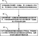
本发明实施例提供了一种以太网中的数据传输方法,应用于以太网业务处理系统,所述以太网业务处理系统包括至少两个交换板,一个业务板,每个所述交换板通过物理链路与每个所述业务板相连,该数据传输方法的处理流程如图1所示,包括如下步骤:The embodiment of the present invention provides a data transmission method in Ethernet, which is applied to an Ethernet service processing system. The Ethernet service processing system includes at least two switching boards and one service board. The link is connected to each of the service boards, and the processing flow of the data transmission method is as shown in Figure 1, including the following steps:
S101、当第一交换板以太网传输发生故障时,所述第一交换板通过所述物理链路向每个所述业务板发送状态指示信号指示所述第一交换板以太网数据传输发生故障;S101. When the Ethernet transmission failure of the first switch board occurs, the first switch board sends a status indication signal to each of the service boards through the physical link to indicate that the Ethernet data transmission failure of the first switch board occurs ;
S102、使得每个所述业务板停止通过所述第一交换板进行数据交换,而通过第二交换板进行以太网数据交换。S102. Make each of the service boards stop performing data exchange through the first switch board, and perform Ethernet data exchange through the second switch board.
实施例二Embodiment two
该实施例提供的一种以太网中业务板、交换板的应用场景的示意图如图2所示,在图2中,包括至少两个交换板以及多个业务板,图2中以两个交换板以及二个业务板为例进行说明。参见图2,每个业务板到第一交换板、第二交换板都通过以太网链路连接;每个交换板也通过以太网链路与每个业务板相连,每个交换板中的以太网交换模块通过以太网链路和每个业务板中的业务处理模块之间进行以太网数据传输;同时,第一交换板、第二交换板之间通过HiGig链路连接。A schematic diagram of an application scenario of a service board and a switch board in an Ethernet provided by this embodiment is shown in FIG. 2. In FIG. 2, at least two switch boards and multiple service boards are included. In FIG. board and two business boards as an example. Referring to Fig. 2, each service board is connected to the first switch board and the second switch board through an Ethernet link; each switch board is also connected to each service board through an Ethernet link, and the Ethernet in each switch board The network switching module performs Ethernet data transmission between the service processing modules in each service board through the Ethernet link; at the same time, the first switching board and the second switching board are connected through HiGig links.
本发明实施例中,每个交换板中的控制模块还通过一条或多条物理链路与每个业务板进行连接,用于输出状态指示信号。这里的物理链路实现形式并不限定,例如,可以利用PCB(Printed Circuit Board,印制电路板)上的走线进行连接,或者使用外接的连线进行连接。本发明实施例为了系统设计布线的简洁,采用直接使用PCB上的走线进行相连。通过物理链路,可以对信号进行快速地传输。In the embodiment of the present invention, the control module in each switching board is also connected to each service board through one or more physical links, and is used for outputting status indication signals. The implementation form of the physical link here is not limited, for example, it can be connected by wiring on a PCB (Printed Circuit Board, printed circuit board), or by using an external connection. In the embodiment of the present invention, in order to simplify the system design and wiring, the wiring on the PCB is directly used for connection. Through the physical link, the signal can be transmitted quickly.
在进行具体连接时,无论是物理链路,还是交换板与业务板相连的以太网链路,都可以通过每个板(业务板或交换板)的背板连接器连接到背板,再通过背板上的走线实现信号的相连。When making a specific connection, whether it is a physical link or an Ethernet link connecting a switch board to a service board, it can be connected to the backplane through the backplane connector of each board (service board or switch board), and then connected to the backplane through the The wiring on the backplane realizes the connection of signals.
如图3所示,交换板上的端口PIN1先通过本板上的走线x1(印刷电路板中绘制)连接到背板连接器,再通过背板连接器与背板相连;业务板上的端口PIN1′也先通过本板上的走线x1′与背板连接器相连,再通过背板连接器与背板相连;同时,在背板上再通过相应的走线x2实现PIN1与PIN1′的信号连接。上述端口是指基于某个硬件电路的引脚,如DSP、FPGA、ASIC等硬件芯片的一个引脚。As shown in Figure 3, the port PIN1 on the switch board is first connected to the backplane connector through the trace x1 (drawn on the printed circuit board) on the board, and then connected to the backplane through the backplane connector; The port PIN1' is first connected to the backplane connector through the wiring x1' on the board, and then connected to the backplane through the backplane connector; at the same time, PIN1 and PIN1' are realized on the backplane through the corresponding wiring x2 signal connection. The above-mentioned port refers to a pin based on a certain hardware circuit, such as a pin of a hardware chip such as DSP, FPGA, and ASIC.
需要说明的是,本领域技术人员可以通过公知常识知道,在与背板连接器相连时,本板上也会设置有对应的连接器来与背板连接器进行连接。在本发明实施例中,也可以将这一套连接器称为“背板连接器”,因此,本发明实施例中的背板连接器既可以指只连接背板上的连接器,还可以包括交换板(或业务板)上的连接器,在此并不对“背板连接器”一词进行严格区分。本领域技术人员可以根据“背板连接器”一词来对交换板(或业务板)与背板进行连接。It should be noted that those skilled in the art can know from common knowledge that when connecting to the backplane connector, the board will also be provided with a corresponding connector to connect to the backplane connector. In the embodiment of the present invention, this set of connectors can also be called "backplane connector". Therefore, the backplane connector in the embodiment of the present Including connectors on switch boards (or service boards), the term "backplane connector" is not strictly distinguished here. Those skilled in the art can connect the switch board (or service board) and the backplane according to the term "backplane connector".
这里的背板连接器可以是欧式连接器、ZD连接器、AirMax连接器、金手指连接器等多种连接器,在此并不限定;同时,背板连接器可以连接一个端口信号,也可以连接多个端口信号,在此也不限定。The backplane connector here can be a variety of connectors such as European connectors, ZD connectors, AirMax connectors, gold finger connectors, etc., and is not limited here; at the same time, the backplane connector can be connected to a port signal or Connecting multiple port signals is also not limited here.
如果交换板输出的状态指示信号的驱动能力较强,则可以通过一个交换板的端口给多个业务板提供信号,如一个端口给3个业务板提供信号;反之,如果交换板输出的状态指示信号的驱动能力较弱,一个端口能驱动的业务板数量也要减少,如一个端口只给一个业务板提供信号,此时,如果想提供多个业务板信号,需要多个端口来完成。If the driving capability of the status indication signal output by the switch board is strong, then one port of the switch board can provide signals to multiple service boards, such as one port provides signals to three service boards; The driving ability of the signal is weak, and the number of service boards that can be driven by one port should also be reduced. For example, one port only provides signals for one service board. At this time, if you want to provide signals for multiple service boards, you need multiple ports to complete.
基于上述图2所示的应用场景,该实施例提供的一种以太网中的数据传输方法的处理流程如图4所示,包括如下的处理步骤:Based on the above-mentioned application scenario shown in FIG. 2, the processing flow of a data transmission method in Ethernet provided by this embodiment is shown in FIG. 4, including the following processing steps:
步骤41、业务板获取并存储第一交换板、第二交换板的工作状态、所关联的以太网端口的物理层状态和链路层状态。
第一交换板、第二交换板都处于正常运行工作状态,第一交换板、第二交换板中的控制模块都通过其连接物理链路的端口输出状态指示信号。上述状态指示信号所表示的含义可以自定义,在本发明实施例中,以携带脉冲电平的状态指示信号表示工作状态正常,以携带固定电平的状态指示信号表示工作状态故障;或者,以携带第一固定电平(如高电平)的状态指示信号表示工作状态正常,以携带第一固定电平(如低电平)的状态指示信号表示工作状态故障。Both the first switch board and the second switch board are in a normal operating state, and the control modules in the first switch board and the second switch board output status indication signals through their ports connected to the physical link. The meaning indicated by the above status indication signal can be customized. In the embodiment of the present invention, the status indication signal carrying a pulse level indicates that the working status is normal, and the status indicating signal carrying a fixed level indicates a working status failure; or, using A state indicating signal carrying a first fixed level (such as a high level) indicates a normal working state, and a state indicating signal carrying a first fixed level (such as a low level) indicates a working state failure.
由于,第一交换板、第二交换板都处于正常运行工作状态,因此,上述第一交换板、第二交换板中的控制模块通过其连接物理链路的端口输出携带脉冲电平或低电平的状态指示信号,上述状态指示信号通过物理链路传输,可以被各个业务板快速地接收到。当业务板获取上述状态指示信号中携带的脉冲电平或低电平时,根据该脉冲电平或低电平获取第一交换板、第二交换板的工作状态为正常。Since both the first switch board and the second switch board are in the normal operating state, the control modules in the above-mentioned first switch board and the second switch board output a pulse level or low power through the port connected to the physical link. Flat status indication signal, the above status indication signal is transmitted through the physical link, and can be quickly received by each service board. When the service board obtains the pulse level or low level carried in the above status indication signal, it obtains that the working status of the first switching board and the second switching board is normal according to the pulse level or low level.
上述第一交换板、第二交换板都分别对应一个槽位,每个槽位关联一个或多个以太网端口(端口数量与相连的业务板数量对应,如连了3块业务板,则需要3个以太网端口)。每个业务板还可以通过Ethernet OAM(Operation,Administration and Maintenance,操作、管理与维护)、LACP等软件协议检测出第一交换板、第二交换板关联的以太网端口的物理层状态和链路层状态。The first switch board and the second switch board above correspond to a slot respectively, and each slot is associated with one or more Ethernet ports (the number of ports corresponds to the number of connected service boards, if 3 service boards are connected, you need to 3 Ethernet ports). Each service board can also detect the physical layer status and link status of the Ethernet ports associated with the first switch board and the second switch board through Ethernet OAM (Operation, Administration and Maintenance, operation, management and maintenance), LACP and other software protocols. layer state.
当第一交换板或第二交换板的工作状态、所关联的以太网端口的物理层状态和链路层状态都处于正常状态时,第一交换板或第二交换板才能够正常进行数据交换等工作。When the working status of the first switching board or the second switching board, the physical layer status and the link layer status of the associated Ethernet port are all in a normal state, the first switching board or the second switching board can normally perform data exchange Waiting for work.
每个业务板将获取的第一交换板、第二交换板的工作状态、所关联的以太网端口的物理层状态和链路层状态进行存储。Each service board stores the acquired working statuses of the first switching board and the second switching board, and the physical layer status and the link layer status of the associated Ethernet ports.
步骤42、出现故障的第一交换板通过物理链路输出状态指示信号,业务板根据该状态指示信号将存储的第一交换板的工作状态进行更新。Step 42: The first switch board that has failed outputs a status indication signal through the physical link, and the service board updates the stored working status of the first switch board according to the status indication signal.
当第一交换板因为其内部的时钟模块、设备监控模块或业务进程等原因发生故障时,第一交换板的工作状态将变为故障。于是,第一交换板中的控制模块通过其连接物理链路的端口输出携带固定电平或高电平的状态指示信号,上述固定电平或高电平表示第一交换板的工作状态为故障。When the first switch board fails due to reasons such as its internal clock module, device monitoring module, or service process, the working state of the first switch board will change to failure. Therefore, the control module in the first switch board outputs a status indication signal carrying a fixed level or a high level through its port connected to the physical link, and the above-mentioned fixed level or high level indicates that the working status of the first switch board is failure .
上述第一交换板还关掉和第二交换板之间的HiGig链路,该HiGig链路用于在第一交换板和第二交换板之间传输数据。然后,第一交换板启动计时操作,在预定的计时时长到达后,第一交换板进行复位操作。The first switch board also shuts down the HiGig link between the first switch board and the second switch board, and the HiGig link is used to transmit data between the first switch board and the second switch board. Then, the first switch board starts a timing operation, and after the predetermined time period reaches, the first switch board performs a reset operation.
由于业务板都通过物理链路和每个交换板相连,上述第一交换板发送的携带固定电平或高电平的状态指示信号将很快被各个业务板接收到。每个业务板根据该固定电平或高电平信息获取第一交换板的工作状态为故障。Since the service boards are connected to each switch board through a physical link, the status indication signal carrying a fixed level or a high level sent by the first switch board will be quickly received by each service board. Each service board obtains the working status of the first switching board as failure according to the fixed level or high level information.
于是,各个业务板将存储的第一交换板的工作状态信息从正常变更为故障。Then, each service board changes the stored working status information of the first switching board from normal to faulty.
每个业务板还按照预定的检测周期检测出第一交换板、第二交换板对应的槽位所关联的以太网端口的物理层状态和链路层状态,并根据检测结果对存储的第一交换板、第二交换板对应的槽位所关联的以太网端口的物理层状态和链路层状态进行更新。Each service board also detects the physical layer state and the link layer state of the Ethernet ports associated with the corresponding slots of the first switch board and the second switch board according to a predetermined detection cycle, and according to the detection results, the stored first The physical layer state and the link layer state of the Ethernet port associated with the corresponding slot of the switch board and the second switch board are updated.
步骤43、各个业务板根据存储的交换板的工作状态、所关联的以太网端口的物理层状态和链路层状态等信息,选择合适的交换板进行数据交换。
各个业务板根据存储的第一交换板、第二交换板的工作状态、所关联的以太网端口的物理层状态和链路层状态等信息,按照预先设置的交换板选路原则选择合适的交换板进行数据交换。Each service board selects an appropriate switching board based on the stored information such as the working status of the first switching board and the second switching board, the physical layer status and the link layer status of the associated Ethernet ports, and according to the preset routing principle of the switching board. board for data exchange.
上述预先设置的交换板选择原则可以通过如下的表1来表示:The above pre-set switch board selection principles can be expressed by the following table 1:
表1:Table 1:

依据上述表1所示的交换板选择原则,当一个交换板的工作状态、以太网端口物理层状态、以太网端口链路层状态中的至少一项处于故障状态时,该交换板便被认为是不可用的,只有一个交换板的工作状态、以太网端口物理层状态、以太网端口链路层状态都处于正常状态时,该交换板才被认为是可用的。According to the switching board selection principle shown in Table 1 above, when at least one of the working status, Ethernet port physical layer status, and Ethernet port link layer status of a switching board is in a fault state, the switching board is considered It is unavailable. Only when the working state of a switch board, the physical layer status of the Ethernet port, and the link layer status of the Ethernet port are all in the normal state, the switch board is considered available.
对于不可用的交换板,比如,该实施例中的第一交换板,各个业务板将到第一交换板的以太网链路设置为不可用,不向到第一交换板的以太网链路发送数据,而向第二交换板的以太网链路上发送数据。但各个业务板在接收侧,还接收从到第一交换板的以太网链路上传输过来的数据,以避免上述第一交换板已经发送的正在以太网链路上传输的数据包掉包。For unavailable switch boards, such as the first switch board in this embodiment, each service board sets the Ethernet link to the first switch board as unavailable, and does not connect to the Ethernet link to the first switch board. Send data, and send data to the Ethernet link of the second switch board. However, on the receiving side, each service board also receives the data transmitted from the Ethernet link to the first switch board, so as to avoid packet loss of the data packets sent by the first switch board and being transmitted on the Ethernet link.
在该实施例中,第二交换板的工作状态、以太网端口物理层状态和以太网端口链路层状态都是正常的,第二交换板是可用的。于是,各个业务板将需要发送给第一交换板的数据,通过和第二交换板之间的以太网链路发送给第二交换板,让第二交换板来分担出现故障的第一交换板的流量。In this embodiment, the working state of the second switch board, the physical layer state of the Ethernet port, and the link layer state of the Ethernet port are all normal, and the second switch board is available. Therefore, each service board sends the data that needs to be sent to the first switch board to the second switch board through the Ethernet link between the second switch board, so that the second switch board can share the data of the failed first switch board. traffic.
然后,第一交换板在故障消除后,第一交换板中的控制模块通过其连接物理链路的端口输出携带脉冲电平或低电平的状态指示信号。业务板检测到第一交换板的状态恢复后,又可以向该交换板的以太网链路发送数据。Then, after the fault of the first switch board is eliminated, the control module in the first switch board outputs a state indication signal carrying a pulse level or a low level through its port connected to the physical link. After the service board detects that the state of the first switch board is recovered, it can send data to the Ethernet link of the switch board.
本发明实施例通过交换板利用物理链路主动向业务板发送指示交换板工作状态信息的状态指示信号,无需按照软件协议规定的发送周期进行发送,由于物理链路传输信号所需的时间很短,因此,可以使业务板及时获取交换板的工作状态信息,并根据各个交换板的工作状态信息选择其他合适的交换板进行数据传输,从而大大降低了对业务的影响程度。In the embodiment of the present invention, the switching board utilizes the physical link to actively send the status indication signal indicating the working state information of the switching board to the service board, without sending according to the sending period specified in the software protocol, because the time required for the physical link to transmit the signal is very short Therefore, the service board can obtain the working status information of the switching board in time, and select other suitable switching boards for data transmission according to the working status information of each switching board, thereby greatly reducing the impact on services.
实施例三Embodiment three
本发明实施例还提供了一种以太网中的数据传输系统,包括:至少两个交换板和至少一个业务板,每个交换板通过物理链路与每个业务板相连;The embodiment of the present invention also provides a data transmission system in Ethernet, including: at least two switching boards and at least one service board, each switching board is connected to each service board through a physical link;
当第一交换板的以太网数据传输发生故障时,第一交换板通过所述物理链路向所述业务板发送状态指示信号指示所述第一交换板发生故障;When the Ethernet data transmission of the first switch board fails, the first switch board sends a status indication signal to the service board through the physical link to indicate that the first switch board fails;
业务板收到交换板发送的状态指标信号后,停止通过所述第一交换板进行数据交换,而通过第二交换板进行数据交换。After receiving the status indicator signal sent by the switch board, the service board stops data exchange through the first switch board, and performs data exchange through the second switch board.
参见图2,以本发明实施例包括两个交换板、两个业务板为例进行说明;其中,为了将两个交换板、业务板进行区分,分别命名为第一交换板、第二交换板;以及第一业务板、第二业务板。Referring to Fig. 2, the embodiment of the present invention includes two switch boards and two service boards as an example for illustration; wherein, in order to distinguish the two switch boards and service boards, they are respectively named the first switch board and the second switch board ; and the first service board and the second service board.
具体的,每个交换板包括以太网数据交换模块,控制模块和其他模块;每个业务板包括业务处理模块、指示信号处理模块和其他模块。Specifically, each switching board includes an Ethernet data switching module, a control module and other modules; each service board includes a service processing module, an indication signal processing module and other modules.
每个交换板中的以太网数据交换模块,与每个业务板通过以太网链路相连,用于和每个业务板之间进行数据传输及交换;The Ethernet data exchange module in each switch board is connected with each service board through an Ethernet link, and is used for data transmission and exchange with each service board;
每个交换板中的控制模块,通过物理链路和背板相连,再通过背板和每个业务板相连,用于当以太网数据传输发生故障(如以太网数据交换模块故障,或者连接的故障)时,通过物理链路向业务板输出状态指示信号,来指示发生故障。The control module in each switch board is connected to the backplane through a physical link, and then connected to each service board through the backplane. In the event of a fault), the physical link outputs a status indication signal to the service board to indicate the occurrence of a fault.
在实际应用中,所述的控制模块,可以输出携带脉冲电平的状态指示信号表示所述交换板状态正常,输出携带固定电平的状态指示信号表示所述交换板状态发生故障;或者,输出携带第一固定电平(如高电平)的状态指示信号表示所述交换板状态正常,输出携带第二固定电平(如低电平)的状态指示信号表示所述交换板状态发生故障。In practical applications, the control module may output a status indication signal carrying a pulse level to indicate that the switch board is in a normal state, and output a status indication signal carrying a fixed level to indicate that the status of the switch board is faulty; or output A status indication signal carrying a first fixed level (such as a high level) indicates that the status of the switching board is normal, and outputting a status indication signal carrying a second fixed level (eg, a low level) indicates that the status of the switching board is faulty.
每个业务板中的指示信号处理模块,用于接收第一交换板输出的指示第一交换板发生故障的状态指示信号,接收第二交换板输出的指示第二交换板状态正常的状态指示信号,向业务处理模块发送停止通过第一交换板进行数据交换、而通过第二交换板进行数据交换的控制命令;The indication signal processing module in each service board is used to receive the status indication signal output by the first switching board indicating that the first switching board is faulty, and receive the status indicating signal output by the second switching board indicating that the status of the second switching board is normal , sending a control command to the service processing module to stop data exchange through the first switch board and perform data exchange through the second switch board;
每个业务板中的业务处理模块,用于根据所述指示信号处理模块发送的所述控制命令,停止通过所述第一交换板进行数据交换,而通过第二交换板进行数据交换。The service processing module in each service board is configured to stop data exchange through the first switch board and perform data exchange through the second switch board according to the control command sent by the indication signal processing module.
每个交换板或业务板中的其他模块是指系统正常运行或根据实际业务情况所需的一些模块,如电源模块,用于提供各种电源;监控模块,用于对系统一些参数进行监控(如温度)。Other modules in each switching board or service board refer to some modules required by the normal operation of the system or according to actual business conditions, such as the power supply module, which is used to provide various power supplies; the monitoring module, which is used to monitor some parameters of the system ( such as temperature).
上述物理链路的实现方式可以为:每个交换板上的端口先通过交换板上的走线连接到交换板上的背板连接器,再通过交换板上的背板连接器与背板相连,所述背板与业务板上的背板连接器相连,再通过业务板上的走线连接到业务板上的端口,从而实现了每个所述交换板和业务板之间的物理链路。The implementation of the above physical link can be as follows: the port on each switch board is first connected to the backplane connector on the switch board through the wiring on the switch board, and then connected to the backplane through the backplane connector on the switch board , the backplane is connected to the backplane connector on the service board, and then connected to the port on the service board through the wiring on the service board, thus realizing the physical link between each of the switching boards and the service board .
所述的交换板上的走线、业务板上的走线包括:印制电路板中绘制的走线。所述的背板连接器包括欧式连接器、ZD连接器、AirMax连接器或金手指连接器。The wiring on the switching board and the wiring on the service board include: wiring drawn on a printed circuit board. The backplane connectors include European connectors, ZD connectors, AirMax connectors or gold finger connectors.
本发明实施例中的各模块具体处理流程可参见实施例二中的相关描述,在此不再赘述。For the specific processing flow of each module in the embodiment of the present invention, reference may be made to the related description in Embodiment 2, which will not be repeated here.
其中,本发明实施例中,各单板(交换板或业务板)中各单元的具体实现可以通过专用芯片、通用CPU或其他类似的硬件芯片并结合相关的附属电路来实现,在此并不限定。例如,参见图5,为本发明实施例交换板具体硬件实现的示意图,包括:Wherein, in the embodiment of the present invention, the specific implementation of each unit in each single board (switching board or service board) can be realized by a dedicated chip, a general-purpose CPU or other similar hardware chips combined with related auxiliary circuits, and is not described here. limited. For example, referring to FIG. 5, it is a schematic diagram of specific hardware implementation of the switching board according to the embodiment of the present invention, including:
处理器51,这里的处理器可以是通用的处理器(如CPU、DSP、FPGA等)来实现,也可以采用ASIC等专用集成电路来实现,或专门的处理器(如以太网处理芯片)来实现;其中,这里只示出了一个处理器,可以理解的是,也可以由多个处理器来完成不同模块(如控制模块、以太网数据交换模块)的功能。
存储器52,例如DDR(Double Data Rate,双倍速率同步动态随机存储器)、SDRAM(Synchronous Dynamic Random Access Memory,同步动态随机存储器)、flash(闪存)等,为处理器及相关程序运行、数据存储等提供存储空间,如果处理器内部自带容量足够的存储模块的话,也可以不需要外部的存储器。
附属电路53,为系统正常运行所需的电路,如芯片运行所需的电源电路、滤波电路、接口电路等。The
与此类似,本发明实施例中的业务板也可以采用类似的结构,根据业务需求对处理器芯片类型及种类进行适应性调整即可,在此不再赘述。Similar to this, the service board in the embodiment of the present invention may also adopt a similar structure, and only need to make adaptive adjustments to the type and type of the processor chip according to service requirements, and details will not be repeated here.
本发明实施例通过交换板利用物理链路主动向业务板发送指示交换板工作状态信息的状态指示信号,无需按照软件协议规定的发送周期进行发送,由于物理链路传输信号所需的时间很短,因此,可以使业务板及时获取交换板的工作状态信息,并根据各个交换板的工作状态信息选择其他合适的交换板进行数据传输,从而大大降低了对业务的影响程度。In the embodiment of the present invention, the switching board utilizes the physical link to actively send the status indication signal indicating the working state information of the switching board to the service board, without sending according to the sending period specified in the software protocol, because the time required for the physical link to transmit the signal is very short Therefore, the service board can obtain the working status information of the switching board in time, and select other suitable switching boards for data transmission according to the working status information of each switching board, thereby greatly reducing the impact on services.
综上所述,本发明实施例通过交换板主动向业务板发送携带交换板工作状态信息的状态指示信号,可以使业务板及时获取交换板的工作状态信息,并根据各个交换板的工作状态信息选择合适的交换板进行数据传输。可确保交换板及时进行主备倒换,实现业务板与业务板之间的数据传输不丢包、交换板与业务板之间的数据传输不丢包。To sum up, in the embodiment of the present invention, the switch board actively sends the status indication signal carrying the working status information of the switching board to the service board, so that the service board can obtain the working status information of the switching board in time, and according to the working status information of each switching board Select the appropriate switch board for data transmission. It can ensure that the active/standby switching of the switch board is performed in time, so that the data transmission between the service board and the service board will not lose packets, and the data transmission between the switch board and the service board will not lose packets.
本领域普通技术人员可以理解实现上述实施例方法中的全部或部分流程,是可以通过计算机程序来指令相关的硬件来完成,所述的程序可存储于一计算机可读取存储介质中,该程序在执行时,可包括如上述各方法的实施例的流程。其中,所述的存储介质可为磁碟、光盘、只读存储记忆体(Read-Only Memory,ROM)或随机存储记忆体(Random Access Memory,RAM)等。Those of ordinary skill in the art can understand that all or part of the processes in the methods of the above embodiments can be implemented through computer programs to instruct related hardware, and the programs can be stored in a computer-readable storage medium. During execution, it may include the processes of the embodiments of the above-mentioned methods. Wherein, the storage medium may be a magnetic disk, an optical disk, a read-only memory (Read-Only Memory, ROM) or a random access memory (Random Access Memory, RAM), etc.
以上所述,仅为本发明较佳的具体实施方式,但本发明的保护范围并不局限于此,任何熟悉本技术领域的技术人员在本发明揭露的技术范围内,可轻易想到的变化或替换,都应涵盖在本发明的保护范围之内。因此,本发明的保护范围应该以权利要求的保护范围为准。The above is only a preferred embodiment of the present invention, but the scope of protection of the present invention is not limited thereto. Any person skilled in the art within the technical scope disclosed in the present invention can easily think of changes or Replacement should be covered within the protection scope of the present invention. Therefore, the protection scope of the present invention should be determined by the protection scope of the claims.
Claims (10)
Priority Applications (2)
| Application Number | Priority Date | Filing Date | Title |
|---|---|---|---|
| CN2010102298303ACN101895423A (en) | 2010-07-15 | 2010-07-15 | Data transmission method and system in Ethernet |
| PCT/CN2011/074386WO2011137797A1 (en) | 2010-07-15 | 2011-05-20 | Method and system for data transmission in ethernet |
Applications Claiming Priority (1)
| Application Number | Priority Date | Filing Date | Title |
|---|---|---|---|
| CN2010102298303ACN101895423A (en) | 2010-07-15 | 2010-07-15 | Data transmission method and system in Ethernet |
Publications (1)
| Publication Number | Publication Date |
|---|---|
| CN101895423Atrue CN101895423A (en) | 2010-11-24 |
Family
ID=43104501
Family Applications (1)
| Application Number | Title | Priority Date | Filing Date |
|---|---|---|---|
| CN2010102298303APendingCN101895423A (en) | 2010-07-15 | 2010-07-15 | Data transmission method and system in Ethernet |
Country Status (2)
| Country | Link |
|---|---|
| CN (1) | CN101895423A (en) |
| WO (1) | WO2011137797A1 (en) |
Cited By (11)
| Publication number | Priority date | Publication date | Assignee | Title |
|---|---|---|---|---|
| CN102185753A (en)* | 2011-01-30 | 2011-09-14 | 广东佳和通信技术有限公司 | Device for realizing dual-backup switching of Ethernet link inside communication equipment |
| WO2011137797A1 (en)* | 2010-07-15 | 2011-11-10 | 华为技术有限公司 | Method and system for data transmission in ethernet |
| WO2012083615A1 (en)* | 2010-12-22 | 2012-06-28 | 中兴通讯股份有限公司 | Ethernet port protecting method and apparatus |
| CN103229470A (en)* | 2012-12-28 | 2013-07-31 | 华为技术有限公司 | Communication system |
| CN103780516A (en)* | 2012-10-19 | 2014-05-07 | 华为技术有限公司 | Three-dimension backboard |
| CN104917700A (en)* | 2015-05-25 | 2015-09-16 | 北京卓越信通电子股份有限公司 | Management unit and exchange unit dual-redundancy switch |
| CN105991309A (en)* | 2015-01-30 | 2016-10-05 | 杭州迪普科技有限公司 | Data sending control method and data sending control device |
| CN106612243A (en)* | 2015-10-21 | 2017-05-03 | 中兴通讯股份有限公司 | A backboard component and a communication device |
| CN108768757A (en)* | 2018-07-26 | 2018-11-06 | 迈普通信技术股份有限公司 | Fault handling method, device, distributed network equipment |
| CN109120558A (en)* | 2017-06-26 | 2019-01-01 | 中兴通讯股份有限公司 | A kind of automatic method for removing of veneer port failure and system |
| CN113037653A (en)* | 2019-12-24 | 2021-06-25 | 中兴通讯股份有限公司 | Switching device, control method, control device, terminal device and storage medium |
Citations (3)
| Publication number | Priority date | Publication date | Assignee | Title |
|---|---|---|---|---|
| CN101022388A (en)* | 2007-03-23 | 2007-08-22 | 毛德操 | Method for constituting self-healing ring with ordinery Ethernet technique |
| CN101047538A (en)* | 2006-03-31 | 2007-10-03 | 上海贝尔阿尔卡特股份有限公司 | Seamless switch-over system of data link based on Ethernet exchange and its method |
| CN101764736A (en)* | 2008-11-10 | 2010-06-30 | 西安新邮通信设备有限公司 | Method for using standard ATCA equipment |
Family Cites Families (3)
| Publication number | Priority date | Publication date | Assignee | Title |
|---|---|---|---|---|
| CN1248425C (en)* | 2002-02-07 | 2006-03-29 | 华为技术有限公司 | Exchange method between on-line and off-line communicator |
| CN100502253C (en)* | 2006-03-24 | 2009-06-17 | 华为技术有限公司 | Realization method of communication equipment, main control board and service board active/standby switchover |
| CN101895423A (en)* | 2010-07-15 | 2010-11-24 | 华为技术有限公司 | Data transmission method and system in Ethernet |
- 2010
- 2010-07-15CNCN2010102298303Apatent/CN101895423A/enactivePending
- 2011
- 2011-05-20WOPCT/CN2011/074386patent/WO2011137797A1/enactiveApplication Filing
Patent Citations (3)
| Publication number | Priority date | Publication date | Assignee | Title |
|---|---|---|---|---|
| CN101047538A (en)* | 2006-03-31 | 2007-10-03 | 上海贝尔阿尔卡特股份有限公司 | Seamless switch-over system of data link based on Ethernet exchange and its method |
| CN101022388A (en)* | 2007-03-23 | 2007-08-22 | 毛德操 | Method for constituting self-healing ring with ordinery Ethernet technique |
| CN101764736A (en)* | 2008-11-10 | 2010-06-30 | 西安新邮通信设备有限公司 | Method for using standard ATCA equipment |
Cited By (18)
| Publication number | Priority date | Publication date | Assignee | Title |
|---|---|---|---|---|
| WO2011137797A1 (en)* | 2010-07-15 | 2011-11-10 | 华为技术有限公司 | Method and system for data transmission in ethernet |
| WO2012083615A1 (en)* | 2010-12-22 | 2012-06-28 | 中兴通讯股份有限公司 | Ethernet port protecting method and apparatus |
| CN102185753B (en)* | 2011-01-30 | 2013-10-30 | 广东佳和通信技术有限公司 | Device for realizing dual-backup switching of Ethernet link inside communication equipment |
| CN102185753A (en)* | 2011-01-30 | 2011-09-14 | 广东佳和通信技术有限公司 | Device for realizing dual-backup switching of Ethernet link inside communication equipment |
| US9445509B2 (en) | 2012-10-19 | 2016-09-13 | Huawei Technologies Co., Ltd. | Three-dimensional backplane |
| CN103780516A (en)* | 2012-10-19 | 2014-05-07 | 华为技术有限公司 | Three-dimension backboard |
| CN103229470B (en)* | 2012-12-28 | 2017-05-24 | 华为技术有限公司 | Communication system |
| CN103229470A (en)* | 2012-12-28 | 2013-07-31 | 华为技术有限公司 | Communication system |
| WO2014101136A1 (en)* | 2012-12-28 | 2014-07-03 | 华为技术有限公司 | Communication system |
| CN105991309A (en)* | 2015-01-30 | 2016-10-05 | 杭州迪普科技有限公司 | Data sending control method and data sending control device |
| CN105991309B (en)* | 2015-01-30 | 2019-08-06 | 杭州迪普科技股份有限公司 | Data sending control method and device |
| CN104917700A (en)* | 2015-05-25 | 2015-09-16 | 北京卓越信通电子股份有限公司 | Management unit and exchange unit dual-redundancy switch |
| CN106612243A (en)* | 2015-10-21 | 2017-05-03 | 中兴通讯股份有限公司 | A backboard component and a communication device |
| CN109120558A (en)* | 2017-06-26 | 2019-01-01 | 中兴通讯股份有限公司 | A kind of automatic method for removing of veneer port failure and system |
| CN108768757A (en)* | 2018-07-26 | 2018-11-06 | 迈普通信技术股份有限公司 | Fault handling method, device, distributed network equipment |
| CN108768757B (en)* | 2018-07-26 | 2021-10-08 | 迈普通信技术股份有限公司 | Fault processing method and device and distributed network equipment |
| CN113037653A (en)* | 2019-12-24 | 2021-06-25 | 中兴通讯股份有限公司 | Switching device, control method, control device, terminal device and storage medium |
| CN113037653B (en)* | 2019-12-24 | 2024-05-28 | 中兴通讯股份有限公司 | Switching device, control method, device, terminal device and storage medium |
Also Published As
| Publication number | Publication date |
|---|---|
| WO2011137797A1 (en) | 2011-11-10 |
Similar Documents
| Publication | Publication Date | Title |
|---|---|---|
| CN101895423A (en) | Data transmission method and system in Ethernet | |
| CN102984059B (en) | Gigabit Ethernet redundancy network interface card and link switching condition criterion output control method thereof | |
| CN100534048C (en) | Distributed Ethernet System and Fault Detection Method Based on the System | |
| US10891242B2 (en) | Embedded USB2 (eUSB2) repeater operation | |
| CN102104531B (en) | Message processing device, method and system | |
| CN101980476B (en) | Warm backup method and network equipment | |
| CN108632099B (en) | Fault detection method and device for link aggregation | |
| WO2009023996A1 (en) | Method for implementing network interconnect via link aggregation | |
| WO2015131516A1 (en) | Distributed intelligent platform management bus connection method and atca frame | |
| CN112217658B (en) | Stacking and splitting processing method and device | |
| CN106301871A (en) | A kind of forwarding detection (BFD) method based on lacp and system | |
| CN108664443B (en) | Data communication synchronization method and system | |
| CN102595260A (en) | Data exchange system and operating mode self-negotiation method thereof | |
| CN105763488B (en) | Data center aggregation core switch and backboard thereof | |
| US20200136912A1 (en) | Method, Device, and System for Implementing MUX Machine | |
| CN114095462B (en) | Fault-tolerant method and system for SRIO communication system of radar processor | |
| CN116781573A (en) | Fault detection method, device, equipment, system and computer-readable storage medium | |
| CN108234308B (en) | Distributed equipment internal communication system and method | |
| CN119603227A (en) | Communication channel switching method, server and electronic equipment | |
| CN119030615A (en) | A method and system for establishing a server transmission protocol optical interconnection link | |
| US9705823B2 (en) | Port status synchronization method, related device, and system | |
| CN118449803A (en) | A communication device for energy storage converter and related devices | |
| CN106330357B (en) | A SERDES transmission verification method, node and system | |
| WO2024139743A1 (en) | Network interface card, single board, electronic device, and service switchover method | |
| CN204633800U (en) | A switch with double redundancy of management unit and switching unit |
Legal Events
| Date | Code | Title | Description |
|---|---|---|---|
| C06 | Publication | ||
| PB01 | Publication | ||
| C10 | Entry into substantive examination | ||
| SE01 | Entry into force of request for substantive examination | ||
| WD01 | Invention patent application deemed withdrawn after publication | Application publication date:20101124 | |
| WD01 | Invention patent application deemed withdrawn after publication |