CN101893060A - Adaptive anti-backlash gear transmission mechanism based on compliant structure - Google Patents
Adaptive anti-backlash gear transmission mechanism based on compliant structureDownload PDFInfo
- Publication number
- CN101893060A CN101893060ACN 201010249358CN201010249358ACN101893060ACN 101893060 ACN101893060 ACN 101893060ACN 201010249358CN201010249358CN 201010249358CN 201010249358 ACN201010249358 ACN 201010249358ACN 101893060 ACN101893060 ACN 101893060A
- Authority
- CN
- China
- Prior art keywords
- groove
- gear transmission
- gear
- compliant structure
- transmission mechanism
- Prior art date
- Legal status (The legal status is an assumption and is not a legal conclusion. Google has not performed a legal analysis and makes no representation as to the accuracy of the status listed.)
- Granted
Links
- 230000005540biological transmissionEffects0.000titleclaimsabstractdescription91
- 230000007246mechanismEffects0.000titleclaimsabstractdescription28
- 230000003044adaptive effectEffects0.000titleabstractdescription5
- 230000008030eliminationEffects0.000abstractdescription4
- 238000003379elimination reactionMethods0.000abstractdescription4
- 230000008901benefitEffects0.000abstractdescription3
- 238000012545processingMethods0.000abstractdescription2
- 238000000034methodMethods0.000description27
- 230000008569processEffects0.000description11
- 238000010586diagramMethods0.000description7
- 230000008859changeEffects0.000description5
- 230000000694effectsEffects0.000description5
- 238000004519manufacturing processMethods0.000description5
- 238000013461designMethods0.000description4
- 230000005489elastic deformationEffects0.000description4
- 230000001788irregularEffects0.000description4
- 238000004458analytical methodMethods0.000description2
- 238000013016dampingMethods0.000description2
- 238000012938design processMethods0.000description2
- 238000006073displacement reactionMethods0.000description2
- 230000006872improvementEffects0.000description2
- 239000007787solidSubstances0.000description2
- 230000009471actionEffects0.000description1
- 230000009286beneficial effectEffects0.000description1
- 239000003638chemical reducing agentSubstances0.000description1
- 238000005516engineering processMethods0.000description1
- 238000012423maintenanceMethods0.000description1
- 239000000463materialSubstances0.000description1
- 230000009347mechanical transmissionEffects0.000description1
- 238000012986modificationMethods0.000description1
- 230000004048modificationEffects0.000description1
- 238000009828non-uniform distributionMethods0.000description1
- 230000008439repair processEffects0.000description1
- 230000006641stabilisationEffects0.000description1
- 238000011105stabilizationMethods0.000description1
- 238000012795verificationMethods0.000description1
Images


Classifications
- F—MECHANICAL ENGINEERING; LIGHTING; HEATING; WEAPONS; BLASTING
- F16—ENGINEERING ELEMENTS AND UNITS; GENERAL MEASURES FOR PRODUCING AND MAINTAINING EFFECTIVE FUNCTIONING OF MACHINES OR INSTALLATIONS; THERMAL INSULATION IN GENERAL
- F16H—GEARING
- F16H55/00—Elements with teeth or friction surfaces for conveying motion; Worms, pulleys or sheaves for gearing mechanisms
- F16H55/02—Toothed members; Worms
- F16H55/17—Toothed wheels
- F16H55/18—Special devices for taking up backlash
Landscapes
- Engineering & Computer Science (AREA)
- General Engineering & Computer Science (AREA)
- Mechanical Engineering (AREA)
- Gears, Cams (AREA)
Abstract
Translated fromChinese
Description
Translated fromChinese技术领域technical field
本发明主要涉及到齿轮传动设备领域,特指一种可自适应消隙的齿轮传动机构。The invention mainly relates to the field of gear transmission equipment, in particular to a gear transmission mechanism capable of self-adaptive backlash elimination.
背景技术Background technique
齿轮传动是指所有以轮齿啮合传动为传动形式的广义的齿轮传动,它包含平行轴齿轮传动、相交轴齿轮传动和交错轴齿轮传动三大类。所以,齿轮传动中的齿轮是广义形式上的齿轮,它包括圆柱齿轮、齿条、锥齿轮、蜗轮、蜗杆、具有变传动比特性的非圆柱齿轮等,其齿形可分为直齿、斜齿、人字齿、曲线(如摆线)齿、曲面(如准双曲面)齿等。Gear transmission refers to all generalized gear transmissions in the form of tooth meshing transmission, which includes three categories: parallel axis gear transmission, intersecting axis gear transmission and cross axis gear transmission. Therefore, gears in gear transmission are gears in a broad sense, including cylindrical gears, racks, bevel gears, worm gears, worms, non-cylindrical gears with variable transmission ratio characteristics, etc. The tooth shape can be divided into straight teeth, helical gears, etc. Teeth, herringbone teeth, curved (such as cycloid) teeth, curved (such as hypoid) teeth, etc.
在齿轮传动系统中,由于制造和装配误差不可避免会带来反向间隙。单纯采用制造高精度齿轮的方法来消除间隙成本过高,也无法实现自适应消隙传动。因此人们通过采用特殊设计、制造和装配方法,在不提高齿轮制造精度的情况下尽可能消除间隙。到目前为止已有多种方法得到应用,几种典型的消除间隙方法或结构如下:In a gear transmission system, backlash is unavoidable due to manufacturing and assembly errors. Simply adopting the method of manufacturing high-precision gears to eliminate backlash is too expensive, and it is impossible to realize adaptive anti-backlash transmission. Therefore, people use special design, manufacturing and assembly methods to eliminate the gap as much as possible without improving the manufacturing accuracy of the gear. A variety of methods have been applied so far, and several typical methods or structures for eliminating gaps are as follows:
1、调整传动轴回转中心位置(径向位置或轴向位置)。通过改变传动轴回转中心位置来减少和控制间隙。该方法的优点是允许存在较大的传动轴中心位置误差和齿轮节圆尺寸误差,主要缺点是只能消除常值间隙,而不能消除变值间隙,且对装配要求较高。在传动精度要求较高的情形下,单纯采用此法消隙效果有限。1. Adjust the rotation center position of the transmission shaft (radial position or axial position). Reduce and control backlash by changing the position of the center of rotation of the transmission shaft. The advantage of this method is that it allows a large error in the center position of the transmission shaft and the size error of the pitch circle of the gear. The main disadvantage is that it can only eliminate the constant value gap, but not the variable value gap, and has high requirements for assembly. In the case of high transmission precision requirements, the effect of simply using this method to eliminate backlash is limited.
2、采用刚性调整齿厚的剪式组合齿轮传动。其实质是通过刚性调整改变组合齿轮的齿厚,对常值间隙进行补偿,其结构相对较简单,但只能消除常值间隙,且平均有效最大啮合齿宽只有总齿宽的二分之一,对结构强度特性和力学特性有影响。2. It adopts scissor combination gear transmission with rigid adjustment of tooth thickness. Its essence is to change the tooth thickness of the combined gear through rigid adjustment, and compensate the constant clearance. Its structure is relatively simple, but it can only eliminate the constant clearance, and the average effective maximum meshing tooth width is only half of the total tooth width. , has an impact on the structural strength properties and mechanical properties.
3、采用弹簧加载调整齿厚的剪式组合齿轮传动。其实质是通过弹簧加载实时改变组合齿轮的齿厚,对常值间隙和变值间隙进行补偿,可连续消除全部间隙,缺点是:1)由于弹簧载力必须大于最大传动负载,因此只限于转矩较低的齿轮传动;2)平均有效最大啮合齿宽只有总齿宽的二分之一,对结构强度特性和力学特性有影响;3)结构、装配工艺相对较复杂,可靠性不高,如果齿轮加载弹簧安装不当,则易出故障。3. Adopt the scissor combination gear transmission with spring loading to adjust the tooth thickness. Its essence is to change the tooth thickness of the combined gear in real time by spring loading, to compensate the constant value gap and the variable value gap, and to continuously eliminate all the gaps. The disadvantages are: 1) Since the spring load must be greater than the maximum transmission load, it is limited to rotation 2) The average effective maximum meshing tooth width is only half of the total tooth width, which has an impact on the structural strength and mechanical properties; 3) The structure and assembly process are relatively complicated and the reliability is not high. Gear loaded springs are prone to failure if they are improperly installed.
4、采用防间隙的辅助齿轮装置。该法是用一个单向加载的辅助齿轮传动链使各齿轮扭紧,形成单侧啮合而消除间隙。该方法可连续消除全部间隙,但结构、装配工艺相对较复杂,且单向附加载荷会影响结构强度特性和力学特性。4. Adopt anti-backlash auxiliary gear device. This method uses a one-way loaded auxiliary gear transmission chain to tighten the gears to form a one-sided mesh and eliminate the backlash. This method can continuously eliminate all gaps, but the structure and assembly process are relatively complex, and the unidirectional additional load will affect the structural strength and mechanical properties.
此外,还有资料报道过具有柔性啮合带的齿轮传动方法和具有啮合带齿的无间隙齿轮传动机构的应用情况。但由于技术的不成熟性或工艺的复杂性,其应用尚不普遍。In addition, there are also reports on the gear transmission method with flexible meshing belts and the application of backlash-free gear transmission mechanisms with meshing belt teeth. However, due to the immaturity of the technology or the complexity of the process, its application is not yet widespread.
以上方法1和方法2只能消除常值间隙,方法3依靠弹簧作用实现消除间隙,但其结构、装配工艺相对较复杂,且在有冲击载荷作用的场合不可靠。方法4结构、装配工艺相对较复杂,且单向附加载荷会影响结构强度特性和力学特性。The
发明内容Contents of the invention
本发明要解决的技术问题就在于:针对现有技术存在的技术问题,本发明提供一种结构简单紧凑、成本低廉、加工方便、适用范围广、实现自适应消隙的基于柔顺结构的自适应消隙齿轮传动机构。The technical problem to be solved by the present invention lies in: aiming at the technical problems existing in the prior art, the present invention provides a self-adaptive compliant structure based on a simple and compact structure, low cost, convenient processing, wide application range, and self-adaptive anti-backlash. Anti-backlash gear transmission mechanism.
为解决上述技术问题,本发明采用以下技术方案。In order to solve the above technical problems, the present invention adopts the following technical solutions.
一种基于柔顺结构的自适应消隙齿轮传动机构,包括两个以上相互啮合的齿轮传动件,其特征在于:所述至少一个齿轮传动件的端面上开设有两圈以上的环形槽,所述相邻两圈的环形槽之间形成柔顺结构。An adaptive anti-backlash gear transmission mechanism based on a compliant structure, comprising more than two gear transmission parts meshing with each other, characterized in that: the end surface of at least one gear transmission part is provided with more than two circles of annular grooves, the A compliant structure is formed between two adjacent circles of annular grooves.
作为本发明的进一步改进:As a further improvement of the present invention:
所述环形槽由两个以上的通槽组成,处于同一圈环形槽中的通槽为不连续分布,所述同一圈环形槽中相邻通槽之间设有固联点。The annular groove is composed of more than two through grooves, and the through grooves in the same circle of annular grooves are discontinuously distributed, and fixed connection points are provided between adjacent through grooves in the same circle of annular grooves.
所述通槽为弧形槽、或长条形槽、或矩形槽、或异形槽。The through groove is an arc groove, or an elongated groove, or a rectangular groove, or a special-shaped groove.
所述各圈环形槽中通槽的数量相同、或各圈环形槽中通槽的数量不相同。The number of through grooves in the annular grooves of each ring is the same, or the number of through grooves in the annular grooves of each ring is different.
所述环形槽与齿轮传动件的齿轮节圆同轴心、或环形槽与齿轮传动件的齿轮节圆不同轴心。The annular groove and the gear pitch circle of the gear transmission part have the same axis, or the annular groove and the gear pitch circle of the gear transmission part have different axes.
与现有技术相比,本发明的优点就在于:Compared with the prior art, the present invention has the advantages of:
1、本发明采用基于柔顺结构的自适应消隙齿轮传动机构,能够获得自适应消除传动间隙的效果,无须采用其它特别设计的消隙手段,就可以真正实现高精度无间隙传动,且可使传动系统兼具良好的刚度和阻尼特性。本发明适合范围广(冲击载荷特别大的场合除外),可广泛适用于精密减速器、精密伺服机构的传动系统,特别是对可控性要求较高的机械传动系统,如高精度姿态稳定/跟踪平台传动机构、精密数控机床传动系统等;1. The present invention adopts an adaptive anti-backlash gear transmission mechanism based on a compliant structure, which can achieve the effect of self-adaptive elimination of transmission backlash, and can truly realize high-precision backlash-free transmission without using other specially designed anti-backlash means, and can make The drivetrain combines good stiffness and damping characteristics. The invention has a wide range of applications (except for occasions where the impact load is particularly large), and can be widely applied to transmission systems of precision reducers and precision servo mechanisms, especially mechanical transmission systems that require high controllability, such as high-precision attitude stability/ Tracking platform transmission mechanism, precision CNC machine tool transmission system, etc.;
2、本发明基于柔顺结构的自适应消隙齿轮传动机构,采用传统的、简单紧凑的传动系统布局方式和传动系统结构型式,所不同的是,在一对相互啮合的传动件中,至少(通常也只须)有一个齿轮(含蜗轮)具有柔顺结构;同时,通过合理设计传动轴中心位置参数(或通过装配调整)、周节误差参数和齿厚参数等措施,保证在一个完整的啮合周期内该柔顺结构在径向方向始终存在一个适度的弹性变形;2. The self-adaptive anti-backlash gear transmission mechanism based on the compliant structure of the present invention adopts a traditional, simple and compact transmission system layout and transmission system structure type. The difference is that in a pair of mutually meshing transmission parts, at least ( Usually, only one gear (including worm gear) has a compliant structure; at the same time, through reasonable design of the transmission shaft center position parameters (or through assembly adjustment), circumferential pitch error parameters and tooth thickness parameters, etc., to ensure a complete meshing During the cycle, the compliant structure always has a moderate elastic deformation in the radial direction;
3、本发明利用柔顺结构的径向刚度特性、周向扭转刚度特性和轴向刚度特性,采用特别设计的具有合理结构型式、结构参数和特性(其周向扭转刚度特性和轴向刚度均远大于其径向刚度)的基于柔顺结构的齿轮传动机构(齿轮或蜗轮),利用其在啮合过程中能够自适应地沿其径向产生弹性位移的特性,获得自适应消隙的效果;3. The present invention utilizes the radial stiffness characteristics, circumferential torsional stiffness characteristics and axial stiffness characteristics of the compliant structure, and adopts a specially designed structure with reasonable structure type, structural parameters and characteristics (its circumferential torsional stiffness characteristics and axial stiffness are both large Due to its radial stiffness), the gear transmission mechanism (gear or worm gear) based on the compliant structure can obtain the effect of self-adaptive anti-backlash by utilizing its characteristic that it can adaptively generate elastic displacement along its radial direction during the meshing process;
4、本发明基于柔顺结构的自适应消隙齿轮传动机构能够有效地完全消除反向间隙,同时可以使传动系统得到良好的刚度和阻尼特性,故特别适用于对机械系统可控性要求较高的场合,如精密伺服传动机构、高精度姿态稳定/跟踪平台传动机构、精密数控机床传动系统等。4. The self-adaptive anti-backlash gear transmission mechanism based on the compliant structure of the present invention can effectively completely eliminate the backlash, and at the same time enable the transmission system to obtain good stiffness and damping characteristics, so it is especially suitable for high controllability requirements of mechanical systems Occasions, such as precision servo transmission mechanism, high-precision attitude stabilization/tracking platform transmission mechanism, precision CNC machine tool transmission system, etc.
附图说明Description of drawings
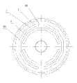
图1是实施例1中外啮合齿轮的主视结构示意图;Fig. 1 is the schematic diagram of the front view structure of the external gear in
图2是图1中A-A处的剖视结构示意图;Fig. 2 is the cross-sectional structure schematic diagram at A-A place in Fig. 1;
图3是实施例1中内啮合齿轮的主视结构示意图;Fig. 3 is the schematic diagram of the front view structure of the internal gear in
图4是实施例2中外啮合齿轮的主视结构示意图;Fig. 4 is the schematic diagram of the front view structure of the external gear in
图5是实施例3中外啮合齿轮的主视结构示意图;Fig. 5 is a front structural schematic view of the external gear in
图6是实施例4中外啮合齿轮的主视结构示意图;Fig. 6 is a schematic diagram of the front view of the external meshing gear in
图7是实施例5中外啮合齿轮的主视结构示意图;Fig. 7 is a schematic diagram of the front view of the external meshing gear in Embodiment 5;
图8是实施例6中外啮合齿轮的主视结构示意图;Fig. 8 is a schematic diagram of the front view of the external meshing gear in Embodiment 6;
图9是实施例7中外啮合齿轮的主视结构示意图。FIG. 9 is a schematic front view of the external gear in Embodiment 7. FIG.
图例说明illustration
1、齿轮传动件;101、外啮合齿轮;102、内啮合齿轮;2、端面;3、环形槽;301、通槽;302、固联点;4、柔顺结构。1. Gear transmission part; 101, external gear; 102, internal gear; 2, end face; 3, annular groove; 301, through groove; 302, solid connection point; 4, compliant structure.
具体实施方式Detailed ways
以下将结合具体实施例和说明书附图对本发明做进一步详细说明。The present invention will be further described in detail below in conjunction with specific embodiments and accompanying drawings.
本发明的基于柔顺结构的自适应消隙齿轮传动机构,包括两个以上相互啮合的齿轮传动件1,至少一个齿轮传动件1的端面2上开设有两圈以上的环形槽3,相邻两圈的环形槽3之间形成柔顺结构4。该环形槽3可以由两个以上的通槽301组成,位于同一圈环形槽3中的通槽301为不连续分布,同一圈环形槽3中相邻通槽301之间设有固联点302。该通槽301可以为弧形槽、或长条形槽、或矩形槽、或异形槽。各圈环形槽3中通槽301的数量相同、或各圈环形槽3中通槽301的数量不相同。环形槽3与齿轮传动件1的齿轮节圆同轴心、或环形槽3与齿轮传动件1的齿轮节圆不同轴心。本发明可适用于圆柱齿轮传动机构、齿轮齿条传动机构、圆锥齿轮传动机构、螺旋齿轮传动机构、蜗轮蜗杆传动机构等等。齿轮传动件1齿圈部分的结构要素可以是直齿轮、螺旋齿轮、锥齿轮或蜗轮等等。本发明的自适应消隙方法通常可以与传动轴回转中心位置调整法一起配合使用。The self-adaptive anti-backlash gear transmission mechanism based on the compliant structure of the present invention includes two or more
本发明无须特别设计的传统的、简单紧凑的传动系统布局方式和传动系统结构型式,能够可靠实现齿轮传动的自适应消隙(同时消除常值和变值间隙),且可使传动系统兼具良好的机械特性。采用本发明的结构,可以简单、便捷地实现传动系统传动间隙故障的维修。在不改变原传动布局方式、传动系统结构的条件下,采用本发明所述的基于柔顺结构且具有合理的齿厚参数的齿轮(含蜗轮),替换原有传动链中的相应齿轮(含蜗轮),即可简单、可靠地修复系统中的传动间隙故障,实现自适应消隙(同时消除常值和变值间隙)。The present invention does not need the traditional, simple and compact transmission system layout and transmission system structure type specially designed, can reliably realize the self-adaptive anti-backlash of gear transmission (eliminate constant value and variable value clearance at the same time), and can make the transmission system both Good mechanical properties. By adopting the structure of the present invention, the maintenance of transmission gap faults of the transmission system can be realized simply and conveniently. Under the condition of not changing the original transmission layout and transmission system structure, the gears (including worm gears) based on the compliant structure and having reasonable tooth thickness parameters described in the present invention are used to replace the corresponding gears (including worm gears) in the original transmission chain. ), which can simply and reliably repair transmission backlash faults in the system, and realize self-adaptive backlash elimination (eliminate constant and variable backlash at the same time).
本发明传动机构的设计过程分步实施如下:The design process of the transmission mechanism of the present invention is implemented step by step as follows:
1、依据传动系统技术要求,确定柔顺结构4的径向刚度参数、周向扭转刚度参数、轴向刚度参数的合理取值范围;1. According to the technical requirements of the transmission system, determine the reasonable value ranges of the radial stiffness parameters, circumferential torsional stiffness parameters, and axial stiffness parameters of the
2、确定传动链的周节精度参数、齿厚精度参数、传动件回转中心位置精度参数(在附图2中,即是合理确定偏差)等主要相关精度参数,由此确定啮合过程中柔顺结构4沿其径向的弹性变形量的合理变化范围(最小值通常不小于10μm。最大值与最小值之差值即变化量,该变化量由传动链的相关精度参数决定,不能太大,以免影响传动系统的机械特性,一般其取值与最小值的量级相当),保证在一个完整的啮合周期内,柔顺结构4沿其径向始终存在一个合理的弹性变形量;2. Determine the main relevant accuracy parameters such as the pitch accuracy parameters of the transmission chain, the tooth thickness accuracy parameters, and the rotation center position accuracy parameters of the transmission parts (in the accompanying drawing 2, that is, to determine the deviation reasonably), so as to determine the compliant structure during the
3、依据上述步骤1、2中所给出的径向刚度/变形量参数、周向扭转刚度/变形量参数、轴向刚度/变形量参数,利用弹性力学理论,并考虑结构工艺性和材料选型,设计出柔顺结构4的合理的结构型式和结构参数;3. Based on the radial stiffness/deformation parameters, circumferential torsional stiffness/deformation parameters, and axial stiffness/deformation parameters given in
4、在上述步骤2中的结构型式和结构参数确定后,必须对所确定的柔顺结构4进行应力/应变分析和疲劳强度校验,建议利用有限元分析工具软件(如ANSYS)对其进行分析和校验;4. After the structural type and structural parameters in the
5、为了得到满足技术需求的设计结果或相对最优化的设计结果,上述设计过程可能需要依序反复多次;5. In order to obtain design results that meet technical requirements or relatively optimal design results, the above design process may need to be repeated several times in sequence;
6、制造和装配参照常规工艺过程进行。6. Manufacture and assembly are carried out according to the conventional process.
下面以具体实施例来说明本发明的结构以及衍生结构。The structure and derived structures of the present invention will be described below with specific examples.
实施例1:以直齿圆柱齿轮传动机构为例,其由两个相互啮合的齿轮传动件1组成的齿轮传动机构为例,其包括相互啮合的外啮合齿轮101和内啮合齿轮102。参见图1和图2所示,外啮合齿轮101的端面2上开设有两圈环形槽3,每圈环形槽3由两个半圆形且不连续布置通槽301组成,该通槽301为弧形槽,所有弧形槽均在端面2上直接加工而成,相邻弧形槽之间设有固联点302。两圈环形槽3之间的区域形成柔顺结构4,上述结构构成“两点正交均布固联同心正圆环形柔顺结构”,该柔顺结构4具有一定弹性,使得齿轮在啮合过程中能够自适应地沿其径向产生弹性位移,从而达到自适应消隙的效果。在使用时,本发明必须通过合理设计(或通过装配调整)传动轴中心位置参数的偏差、合理设计周节误差参数和齿厚参数等措施,保证在一个完整的啮合周期内该柔顺结构4在径向方向始终存在一个适度的弹性变形。参见图3,本实施例中,进一步在内啮合齿轮102的端面2上同样设有柔顺结构4。Embodiment 1: Taking a spur gear transmission mechanism as an example, the gear transmission mechanism composed of two mutually meshing
实施例2:参见图4,本实施例与实施例1基本相同,不同之处在于,每圈环形槽3由三个半圆形且不连续布置的通槽301(即弧形槽)组成,从而构成“三点等间隔错位均布固联正圆环形柔顺结构”,其功能与实施例1基本相同,在此不再赘述。Embodiment 2: Referring to Fig. 4, this embodiment is basically the same as
实施例3:参见图5,本实施例与实施例1基本相同,不同之处在于,位于内圈的环形槽3由四个半圆形且不连续布置的通槽301(即弧形槽)组成,位于外圈的环形槽3由三个半圆形且不连续布置的通槽301(即弧形槽)组成,从而构成“四点等间隔错位均布固联正圆环形柔顺结构”,这样改变固联点302的数目,会改变结构的刚度特性。通过改变柔顺结构4的形状或布置位置,会导致啮合过程中传动的机械特性参数的显著变化,不利于提高传动的机械特性。如果单纯增加其固联302的点数,会导致柔顺结构4的各向刚度的增大,所以过多增加其固联点数对提高消隙效果无益。改变固联方式,可以采用不规则的固联点302数目或不规则的固联点302位置布局方式,如各圈环形槽3之间固联点302的位置可以是数量相同、非均布、非等错位布置(参见图1),也可以是数量不同、布置位置不规则的错位布置(参见图5)。例如图5中所示的几种情形等。改变固联方式,会导致啮合过程中传动的机械特性参数的显著变化,同样不利于提高传动的机械特性;本实施例的功能与实施例1基本相同,在此不再赘述。Embodiment 3: Referring to Fig. 5, this embodiment is basically the same as
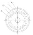
实施例4:参见图6,本实施例与实施例1基本相同,不同之处在于,环形槽3为近似圆环形,其功能与实施例1基本相同,在此不再赘述。Embodiment 4: Referring to FIG. 6, this embodiment is basically the same as
实施例5:参见图7,本实施例与实施例1基本相同,不同之处在于,环形槽3为呈近似环状排列的多边形,其功能与实施例1基本相同,在此不再赘述。Embodiment 5: Referring to FIG. 7, this embodiment is basically the same as
实施例6:参见图8,本实施例与实施例1基本相同,不同之处在于,环形槽3为呈近似环状排列的非规则形,其功能与实施例1基本相同,在此不再赘述。Embodiment 6: Referring to Fig. 8, this embodiment is basically the same as
实施例7:参见图9,本实施例与实施例1基本相同,不同之处在于,环形槽3与端面2呈偏心状布置,与中心轴之间保持距离e,其功能与实施例1基本相同,在此不再赘述。Embodiment 7: Referring to Fig. 9, this embodiment is basically the same as
以上所述仅是本发明的优选实施方式,本发明的保护范围并不仅局限于上述实施例,凡属于本发明思路下的技术方案均属于本发明的保护范围。应当指出,对于本技术领域的普通技术人员来说,在不脱离本发明原理前提下的若干改进和润饰,这些改进和润饰也应视为本发明的保护范围。The above descriptions are only preferred implementations of the present invention, and the protection scope of the present invention is not limited to the above-mentioned embodiments, and all technical solutions under the idea of the present invention belong to the protection scope of the present invention. It should be pointed out that for those skilled in the art, some improvements and modifications without departing from the principles of the present invention should also be regarded as the protection scope of the present invention.
Claims (5)
Priority Applications (1)
| Application Number | Priority Date | Filing Date | Title |
|---|---|---|---|
| CN201010249358XACN101893060B (en) | 2010-08-10 | 2010-08-10 | Self-adaptation clearance-dispelling gear transmission mechanism based on compliant structure |
Applications Claiming Priority (1)
| Application Number | Priority Date | Filing Date | Title |
|---|---|---|---|
| CN201010249358XACN101893060B (en) | 2010-08-10 | 2010-08-10 | Self-adaptation clearance-dispelling gear transmission mechanism based on compliant structure |
Publications (2)
| Publication Number | Publication Date |
|---|---|
| CN101893060Atrue CN101893060A (en) | 2010-11-24 |
| CN101893060B CN101893060B (en) | 2012-01-04 |
Family
ID=43102353
Family Applications (1)
| Application Number | Title | Priority Date | Filing Date |
|---|---|---|---|
| CN201010249358XAExpired - Fee RelatedCN101893060B (en) | 2010-08-10 | 2010-08-10 | Self-adaptation clearance-dispelling gear transmission mechanism based on compliant structure |
Country Status (1)
| Country | Link |
|---|---|
| CN (1) | CN101893060B (en) |
Cited By (17)
| Publication number | Priority date | Publication date | Assignee | Title |
|---|---|---|---|---|
| CN105443724A (en)* | 2015-12-11 | 2016-03-30 | 湖南同晟精传技术有限公司 | Zero-backlash low-noise transmission gear |
| CN107160385A (en)* | 2017-07-07 | 2017-09-15 | 苏州工业园区凯艺精密科技有限公司 | A kind of five axis robots with flexible gear structure |
| CN107191543A (en)* | 2017-07-07 | 2017-09-22 | 苏州工业园区凯艺精密科技有限公司 | Structural formula flexible gear reducing transmission structure |
| CN107336240A (en)* | 2017-07-14 | 2017-11-10 | 苏州工业园区凯艺精密科技有限公司 | A kind of bottom illuminated vision system of manipulator |
| CN107387728A (en)* | 2017-09-13 | 2017-11-24 | 苏州工业园区凯艺精密科技有限公司 | A kind of robot manipulator structure of dismantled and assembled rack |
| CN105426611B (en)* | 2015-11-17 | 2018-08-24 | 天津百利机械装备集团有限公司中央研究院 | A kind of Cycloidal Wheel Parametric Analysis method based on ANSYS |
| CN109185422A (en)* | 2018-10-15 | 2019-01-11 | 南京信息工程大学 | A kind of cup type harmonic speed reducer having both sensing function |
| CN109505951A (en)* | 2018-11-30 | 2019-03-22 | 吴永德 | A kind of gas-fee gare driving mechanism |
| CN109667909A (en)* | 2018-12-06 | 2019-04-23 | 江苏科技大学 | A kind of short cylinder harmonic speed reducer with clearance compensation function |
| CN112594351A (en)* | 2020-12-02 | 2021-04-02 | 陕西航天时代导航设备有限公司 | Fan-shaped gear backlash adjusts structure |
| US20210220062A1 (en)* | 2016-07-14 | 2021-07-22 | Intuitive Surgical Operations, Inc. | Geared roll drive for medical instrument |
| US11805975B2 (en) | 2016-07-14 | 2023-11-07 | Intuitive Surgical Operations, Inc. | Instrument flushing system |
| US11896338B2 (en) | 2017-03-21 | 2024-02-13 | Intuitive Surgical Operations, Inc. | Manual release for medical device drive system |
| US11950873B2 (en) | 2016-07-14 | 2024-04-09 | Intuitive Surgical Operations, Inc. | Multi-cable medical instrument |
| US12048504B2 (en) | 2018-11-15 | 2024-07-30 | Intuitive Surgical Operations, Inc. | Cable drive limited slip capstan and shaft |
| US12076038B2 (en) | 2013-08-15 | 2024-09-03 | Intuitive Surgical Operations, Inc. | Rotary input for lever actuation |
| US12239394B2 (en) | 2019-06-13 | 2025-03-04 | Intuitive Surgical Operations, Inc. | Medical tool with length conservation mechanism for actuating tension bands |
Citations (5)
| Publication number | Priority date | Publication date | Assignee | Title |
|---|---|---|---|---|
| US5911788A (en)* | 1998-02-20 | 1999-06-15 | Sundstrand Corporation | Compliant gear |
| CN2729432Y (en)* | 2004-09-12 | 2005-09-28 | 郑州华萦化纤科技有限责任公司 | Gear with function for removing sideshake of subgear |
| CN1910524A (en)* | 2004-01-13 | 2007-02-07 | 劳力士有限公司 | Toothed wheel for the removal of play,and the use of this gear |
| WO2009069405A1 (en)* | 2007-11-30 | 2009-06-04 | Seiko Precision Inc. | Gear mechanism and blade drive device |
| US7658124B2 (en)* | 2006-07-27 | 2010-02-09 | Caterpillar Inc. | Compliant gear assembly and work machine using same |
- 2010
- 2010-08-10CNCN201010249358XApatent/CN101893060B/ennot_activeExpired - Fee Related
Patent Citations (5)
| Publication number | Priority date | Publication date | Assignee | Title |
|---|---|---|---|---|
| US5911788A (en)* | 1998-02-20 | 1999-06-15 | Sundstrand Corporation | Compliant gear |
| CN1910524A (en)* | 2004-01-13 | 2007-02-07 | 劳力士有限公司 | Toothed wheel for the removal of play,and the use of this gear |
| CN2729432Y (en)* | 2004-09-12 | 2005-09-28 | 郑州华萦化纤科技有限责任公司 | Gear with function for removing sideshake of subgear |
| US7658124B2 (en)* | 2006-07-27 | 2010-02-09 | Caterpillar Inc. | Compliant gear assembly and work machine using same |
| WO2009069405A1 (en)* | 2007-11-30 | 2009-06-04 | Seiko Precision Inc. | Gear mechanism and blade drive device |
Cited By (25)
| Publication number | Priority date | Publication date | Assignee | Title |
|---|---|---|---|---|
| US12076038B2 (en) | 2013-08-15 | 2024-09-03 | Intuitive Surgical Operations, Inc. | Rotary input for lever actuation |
| CN105426611B (en)* | 2015-11-17 | 2018-08-24 | 天津百利机械装备集团有限公司中央研究院 | A kind of Cycloidal Wheel Parametric Analysis method based on ANSYS |
| CN105443724A (en)* | 2015-12-11 | 2016-03-30 | 湖南同晟精传技术有限公司 | Zero-backlash low-noise transmission gear |
| US12310691B2 (en) | 2016-07-14 | 2025-05-27 | Intuitive Surgical Operations, Inc. | Multi-cable medical instrument |
| US12239497B2 (en) | 2016-07-14 | 2025-03-04 | Intuitive Surgical Operations, Inc. | Instrument flushing system |
| US11950873B2 (en) | 2016-07-14 | 2024-04-09 | Intuitive Surgical Operations, Inc. | Multi-cable medical instrument |
| US11864851B2 (en)* | 2016-07-14 | 2024-01-09 | Intuitive Surgical Operations, Inc. | Geared roll drive for medical instrument |
| US11805975B2 (en) | 2016-07-14 | 2023-11-07 | Intuitive Surgical Operations, Inc. | Instrument flushing system |
| US20210220062A1 (en)* | 2016-07-14 | 2021-07-22 | Intuitive Surgical Operations, Inc. | Geared roll drive for medical instrument |
| US12419707B2 (en) | 2016-07-14 | 2025-09-23 | Intuitive Surgical Operations, Inc. | Geared roll drive for medical instrument |
| US11896338B2 (en) | 2017-03-21 | 2024-02-13 | Intuitive Surgical Operations, Inc. | Manual release for medical device drive system |
| US12303225B2 (en) | 2017-03-21 | 2025-05-20 | Intuitive Surgical Operations, Inc. | Manual release for medical device drive system |
| CN107160385B (en)* | 2017-07-07 | 2020-05-12 | 苏州工业园区凯艺精密科技有限公司 | Five-axis manipulator with flexible gear structure |
| WO2019007426A1 (en)* | 2017-07-07 | 2019-01-10 | 苏州工业园区凯艺精密科技有限公司 | Flexible gear reducing transmission structure |
| WO2019007425A1 (en)* | 2017-07-07 | 2019-01-10 | 苏州工业园区凯艺精密科技有限公司 | Mechanical arm with flexible gear structure |
| CN107191543A (en)* | 2017-07-07 | 2017-09-22 | 苏州工业园区凯艺精密科技有限公司 | Structural formula flexible gear reducing transmission structure |
| CN107160385A (en)* | 2017-07-07 | 2017-09-15 | 苏州工业园区凯艺精密科技有限公司 | A kind of five axis robots with flexible gear structure |
| CN107336240A (en)* | 2017-07-14 | 2017-11-10 | 苏州工业园区凯艺精密科技有限公司 | A kind of bottom illuminated vision system of manipulator |
| CN107387728A (en)* | 2017-09-13 | 2017-11-24 | 苏州工业园区凯艺精密科技有限公司 | A kind of robot manipulator structure of dismantled and assembled rack |
| CN109185422A (en)* | 2018-10-15 | 2019-01-11 | 南京信息工程大学 | A kind of cup type harmonic speed reducer having both sensing function |
| US12048504B2 (en) | 2018-11-15 | 2024-07-30 | Intuitive Surgical Operations, Inc. | Cable drive limited slip capstan and shaft |
| CN109505951A (en)* | 2018-11-30 | 2019-03-22 | 吴永德 | A kind of gas-fee gare driving mechanism |
| CN109667909A (en)* | 2018-12-06 | 2019-04-23 | 江苏科技大学 | A kind of short cylinder harmonic speed reducer with clearance compensation function |
| US12239394B2 (en) | 2019-06-13 | 2025-03-04 | Intuitive Surgical Operations, Inc. | Medical tool with length conservation mechanism for actuating tension bands |
| CN112594351A (en)* | 2020-12-02 | 2021-04-02 | 陕西航天时代导航设备有限公司 | Fan-shaped gear backlash adjusts structure |
Also Published As
| Publication number | Publication date |
|---|---|
| CN101893060B (en) | 2012-01-04 |
Similar Documents
| Publication | Publication Date | Title |
|---|---|---|
| CN101893060A (en) | Adaptive anti-backlash gear transmission mechanism based on compliant structure | |
| US10527149B2 (en) | Conjugate gears with continuous tooth flank contact | |
| WO2018040978A1 (en) | Rigid gear for harmonic reducer, harmonic reducer, and robot | |
| KR100988215B1 (en) | Harmonic Reducer Using Potential Gear | |
| US9341252B2 (en) | Wave generator and strain wave gearing | |
| JP6351724B2 (en) | Flat wave gear device | |
| US20170175869A1 (en) | Dual-type strain wave gearing | |
| US11280370B2 (en) | Dual-type strain wave gearing | |
| US8535198B2 (en) | Zero backlash planetary gear train | |
| US20160003338A1 (en) | Strain wave gearing having double-contact negative deflection tooth profile | |
| US8047092B2 (en) | Spiral bevel gear and gear device | |
| US10309513B2 (en) | Dual-type strain wave gearing | |
| US10295037B2 (en) | Dual-type strain wave gearing | |
| US10253863B2 (en) | Dual-type strain wave gearing | |
| CN103615501A (en) | Small harmonic reducer and optimum design method thereof | |
| CN116989101A (en) | Planetary reduction mechanism with small tooth difference and tooth shape design method thereof | |
| US11092223B2 (en) | Dual-type strain wave gearing | |
| US10066724B2 (en) | Strain wave gearing | |
| US10823259B2 (en) | Strain wave gearing having 3-dimensional meshing tooth profile | |
| JP5731277B2 (en) | Flexure meshing gear device and method of manufacturing external gear used therefor | |
| KR101486880B1 (en) | Flexible engagement gear device and method for determining shape of gear tooth of flexible engagement gear device | |
| CN111322374A (en) | An elastic variable transmission ratio wire gear mechanism | |
| KR101690151B1 (en) | Speed reducer with helical conjugate dual cycloid tooth profile | |
| US20240093771A1 (en) | Method for designing cycloidal gear tooth profile of gear shift actuator | |
| CN108488329A (en) | A kind of regulating device of RV retarders return difference |
Legal Events
| Date | Code | Title | Description |
|---|---|---|---|
| C06 | Publication | ||
| PB01 | Publication | ||
| C10 | Entry into substantive examination | ||
| SE01 | Entry into force of request for substantive examination | ||
| C14 | Grant of patent or utility model | ||
| GR01 | Patent grant | ||
| CF01 | Termination of patent right due to non-payment of annual fee | Granted publication date:20120104 Termination date:20170810 | |
| CF01 | Termination of patent right due to non-payment of annual fee |