CN101889900B - Master-slave integrated mechanical arm for assisting minimally invasive surgery - Google Patents
Master-slave integrated mechanical arm for assisting minimally invasive surgeryDownload PDFInfo
- Publication number
- CN101889900B CN101889900BCN2010102232537ACN201010223253ACN101889900BCN 101889900 BCN101889900 BCN 101889900BCN 2010102232537 ACN2010102232537 ACN 2010102232537ACN 201010223253 ACN201010223253 ACN 201010223253ACN 101889900 BCN101889900 BCN 101889900B
- Authority
- CN
- China
- Prior art keywords
- seat
- hand
- axis
- rotating shaft
- shaft
- Prior art date
- Legal status (The legal status is an assumption and is not a legal conclusion. Google has not performed a legal analysis and makes no representation as to the accuracy of the status listed.)
- Active
Links
- 238000002324minimally invasive surgeryMethods0.000titleabstractdescription20
- 230000005540biological transmissionEffects0.000claimsabstractdescription24
- 230000007246mechanismEffects0.000claimsabstractdescription21
- 230000033001locomotionEffects0.000claimsdescription41
- 230000008878couplingEffects0.000claimsdescription10
- 238000010168coupling processMethods0.000claimsdescription10
- 238000005859coupling reactionMethods0.000claimsdescription10
- NJPPVKZQTLUDBO-UHFFFAOYSA-NnovaluronChemical compoundC1=C(Cl)C(OC(F)(F)C(OC(F)(F)F)F)=CC=C1NC(=O)NC(=O)C1=C(F)C=CC=C1FNJPPVKZQTLUDBO-UHFFFAOYSA-N0.000claims4
- 230000001105regulatory effectEffects0.000claims2
- 210000002478hand jointAnatomy0.000abstractdescription54
- 238000010586diagramMethods0.000description11
- 238000000034methodMethods0.000description4
- 238000001356surgical procedureMethods0.000description4
- 230000009286beneficial effectEffects0.000description3
- 230000009471actionEffects0.000description2
- 230000008901benefitEffects0.000description2
- 230000008859changeEffects0.000description2
- 230000008569processEffects0.000description2
- 208000002847Surgical WoundDiseases0.000description1
- 206010052428WoundDiseases0.000description1
- 208000027418Wounds and injuryDiseases0.000description1
- 230000002411adverseEffects0.000description1
- 230000000740bleeding effectEffects0.000description1
- 230000000694effectsEffects0.000description1
- 238000002357laparoscopic surgeryMethods0.000description1
- 230000007774longtermEffects0.000description1
- 238000004519manufacturing processMethods0.000description1
- 230000002980postoperative effectEffects0.000description1
- 238000011084recoveryMethods0.000description1
- 231100000241scarToxicity0.000description1
Images


Landscapes
- Manipulator (AREA)
Abstract
Description
Translated fromChinese技术领域technical field
本发明涉及一种微创外科手术领域内的医疗设备,它可以夹持手术工具辅助医生实施微创手术操作。The invention relates to a medical device in the field of minimally invasive surgical operations, which can hold surgical tools to assist doctors in performing minimally invasive surgical operations.
背景技术Background technique
以腹腔镜为代表的微创外科被誉为20世纪医学科学对人类文明的重要贡献之一,微创手术操作是指医生利用细长的手术工具通过人体表面的微小切口探入到体内进行手术操作的。它与传统的开口手术相比具有手术切口小、出血量少、术后疤痕小、恢复时间快等优点,这使得病人遭受的痛苦大大减少;因此微创外科被广泛的应用于临床手术。然而,微创手术为病人带来了诸多利益的同时,却对医生的操作带来了一系列困难,如:1)由于体表小孔的限制,工具的自由度减少至四个,灵活性大大降低;2)医生操作方向与所期望的方向相反,协调性差;3)医生只能通过监视器上的二维图像获得手术场景信息,缺乏深度方向上的感觉;4)医生手部的抖动可能会被细长的手术工具放大,对手术造成不良影响;5)缺乏力感觉。因此,医生必须经过长期训练才能够进行微创手术操作,即使如此,目前微创手术也仅仅应用在操作相对比较简单的手术过程之中。因此,在微创手术领域中迫切需要一种机器人系统来延伸医生的能力,以便克服上述缺点,使医生能够更容易的完成微创手术操作。目前,能够在临床上使用的微创外科手术机器人系统只有Da Vinci系统和Zeus系统,但它们都有结构复杂、体积庞大、价格昂贵等方面的缺点。国际上如美国、法国、德国、英国、波兰、日本、韩国等地都相继开展了微创外科手术机器人的研究,并产生了一系列样机。我国在机器人辅助手术方面尚处于起步阶段,已经存在的机器人系统只能在手术过程中起辅助定位的作用,并不能应用于临床手术。因此开发一套具有自主知识产权的新型微创外科手术机器人系统对填补我国在该领域的空白有着非常重要的意义。Minimally invasive surgery represented by laparoscopy is known as one of the important contributions of medical science to human civilization in the 20th century. Minimally invasive surgery refers to the use of long and thin surgical tools inserted into the body through tiny incisions on the surface of the human body to perform surgery. operational. Compared with traditional open surgery, it has the advantages of small surgical incision, less bleeding, small postoperative scar, and quick recovery time, which greatly reduces the pain suffered by patients; therefore, minimally invasive surgery is widely used in clinical operations. However, while minimally invasive surgery has brought many benefits to the patient, it has brought a series of difficulties to the doctor's operation, such as: 1) Due to the limitation of small holes on the body surface, the degrees of freedom of the tool are reduced to four, and the flexibility Greatly reduced; 2) The direction of the doctor's operation is opposite to the expected direction, and the coordination is poor; 3) The doctor can only obtain the information of the surgical scene through the two-dimensional image on the monitor, lacking the feeling in the depth direction; 4) The shaking of the doctor's hand It may be magnified by slender surgical tools, causing adverse effects on surgery; 5) Lack of force feeling. Therefore, doctors must undergo long-term training before they can perform minimally invasive surgery. Even so, minimally invasive surgery is currently only used in relatively simple operations. Therefore, in the field of minimally invasive surgery, there is an urgent need for a robot system to extend the ability of doctors, so as to overcome the above-mentioned shortcomings, so that doctors can more easily complete minimally invasive surgery operations. At present, the only minimally invasive surgical robotic systems that can be used clinically are the Da Vinci system and the Zeus system, but they all have the disadvantages of complex structure, bulky size, and high price. The United States, France, Germany, the United Kingdom, Poland, Japan, South Korea and other places in the world have successively carried out research on minimally invasive surgical robots, and produced a series of prototypes. Our country is still in its infancy in robot-assisted surgery. The existing robot system can only play an auxiliary positioning role in the operation process, and cannot be applied to clinical operations. Therefore, it is of great significance to develop a new minimally invasive surgical robot system with independent intellectual property rights to fill the gap in this field in our country.
发明内容Contents of the invention
本发明的目的在于提供辅助微创外科手术的主从一体式机械臂,将机器人的医生操作端和机器人的操作机械臂进行集成,简化了主从式微创手术机器人的结构、体积及控制系统的复杂程度,进而有利于保证手术的安全性。The purpose of the present invention is to provide a master-slave integrated mechanical arm for assisting minimally invasive surgery, integrate the doctor's operating end of the robot with the operating mechanical arm of the robot, and simplify the structure, volume and control system of the master-slave minimally invasive surgical robot The degree of complexity is conducive to ensuring the safety of the operation.
本发明的辅助微创外科手术的主从一体式机械臂它包括主操作端、从操作端、工具夹持端,所述的主操作端包括其上设置有可旋转的主手关节I轴的主手关节I座,主手关节I轴的输出端与其内设置有可旋转的主手关节II轴的主手关节II座相连,所述的主手关节I轴和主手关节II轴的轴线彼此垂直设置,传感器I、II的扭柄分别通过联轴器连接在主手关节I轴及主手关节II轴上,在所述的主手关节II轴上固定有伸缩架,所述的伸缩架的底座与伸缩上座的顶部固定相连;所述的伸缩上座通过直线运动机构与伸缩下座相连以使所述的伸缩下座相对于伸缩上座能够上下移动并通过传感器V记录所述的上下移动,所述的伸缩下座通过轴线沿竖直方向设置的转轴与一个自转座转动相连,一个其轴线与所述的转轴轴线垂直设置的偏转轴安装在所述的自转座上,传感器III和传感器IV的扭柄分别通过联轴器连接在转轴、偏转轴上,在所述的偏转轴上连接有开合座,开合座上安装有开合瓣I和开合瓣II,开合瓣I、开合瓣II之间通过两个连接杆相连,所述的两个连接杆之间通过连接轴相连并且所述的连接轴插在连接在开合座上的直线传感器的开槽中;所述的从操作端包括依次相连的基座部分、主动机械臂部分以及伸缩部分,所述的基座部分包含有基座,所述的基座的一端与主手关节I座的一侧端面相连并且其另一端固定连接有从手关节I座,在所述的从手关节I座内安装有与电机I的输出轴相连的从手关节I轴,在所述的从手关节I座上设置有被动连接面,所述的主动机械臂部分包含与从手关节I轴的输出端固定相连的从手关节II座,丝轮I和丝轮II对称的固定连接在从手关节II座的两侧并且丝轮I和丝轮II的轴线沿与从手关节I轴的输出轴轴线垂直的方向设置,其轴线沿与丝轮I轴线相同方向设置的驱动轴II安装于从手关节II座上,其轴线沿与丝轮I轴线垂直方向设置的驱动轴I通过轴承安装于从手关节II座上,所述的驱动轴I通过联轴器与电机II相连,传感器IV的扭柄与驱动轴I相连;在所述的驱动轴I和驱动轴II之间连接有传动丝I;所述的驱动轴II的两个输出端分别与设置在从手连杆I下端上的两个法兰面固定相连,所述的从手连杆I的上端有三个分支,其中中心孔内设置有轴承的丝轮III和丝轮IV固定连接于从手连杆I的上端中间分支上,从手连杆I的两侧分支上设置有与安装于丝轮III和丝轮IV上的轴承同心的轴承,固定连接于从手连杆II一端的丝轮V、丝轮VI分别通过在其轴心设置的支撑轴与轴承相连,连杆II输出轴通过轴承安装于从手连杆II的另一端,丝轮VII、丝轮VIII固定连接于连杆II输出座上,连杆II输出座与连杆II输出轴固定相连,传动丝II和传动丝III的一端分别固定于丝轮I、丝轮II的丝槽内,经系列导向轮和张紧轮传递后,另一端分别固定于丝轮V和丝轮VI的丝槽内,传动丝IV和传动丝V的一端分别固定于丝轮III和丝轮IV的丝槽内,经导向轮和张紧轮传递后,另一端分别固定于丝轮VII和丝轮VIII的丝槽内,从手伸缩座与连杆II输出座固定相连;在从手伸缩座上设置有导轨,在所述的导轨上安装有滑块,工具夹持端与滑块固定相连,所述的滑块通过传动机构在所述的导轨上滑动。The master-slave integrated mechanical arm for assisting minimally invasive surgery of the present invention includes a master operating end, a slave operating end, and a tool clamping end, and the master operating end includes a rotatable master hand joint I axis on which it is arranged. The main hand joint I seat, the output end of the main hand joint I axis is connected to the main hand joint II seat with a rotatable main hand joint II axis inside, the axis of the main hand joint I axis and the main hand joint II axis The torsion handles of sensors I and II are respectively connected to the main hand joint I axis and the main hand joint II axis through couplings, and a telescopic frame is fixed on the main hand joint II axis. The base of the frame is fixedly connected with the top of the telescopic upper seat; the telescopic upper seat is connected with the telescopic lower seat through a linear motion mechanism so that the telescopic lower seat can move up and down relative to the telescopic upper seat and the sensor V records the up and down movement , the telescopic lower seat is connected to a rotation base through a rotating shaft whose axis is vertically arranged, and a deflection shaft whose axis is perpendicular to the axis of the rotating shaft is installed on the rotation base, and the sensor III and the sensor The torsion handle of IV is respectively connected to the rotating shaft and the deflection shaft through a coupling, and the opening and closing seat is connected to the deflection shaft, and the opening and closing valve I and the opening and closing valve II are installed on the opening and closing seat, and the opening and closing valve I 1. The opening and closing flaps II are connected by two connecting rods, the two connecting rods are connected by a connecting shaft and the connecting shaft is inserted in the slot of the linear sensor connected to the opening and closing seat; The described slave operating end includes a base part, an active mechanical arm part and a telescoping part connected in sequence, and the described base part includes a base, and one end of the base is connected to one side end surface of the main hand joint I seat And its other end is fixedly connected with from the hand joint I seat, in described from the hand joint I seat, the slave hand joint I shaft that links to each other with the output shaft of
本发明辅助微创外科手术的主从一体式机械臂与现有技术相比具有以下有益效果:Compared with the prior art, the master-slave integrated mechanical arm for assisting minimally invasive surgery of the present invention has the following beneficial effects:
1.本发明机械臂将主从式机器人的主操作端和从操作端进行了集成,简化了系统结构,减小了系统体积,进而有利于节省成本,减少了故障率;1. The mechanical arm of the present invention integrates the master operation end and the slave operation end of the master-slave robot, which simplifies the system structure and reduces the system volume, which in turn helps save costs and reduces the failure rate;
2.本发明机械臂的主动机械臂部分的丝传动部分为系统的关键环节,因此设计上每个传动环节设置了两组丝,保证了机械臂在使用上的安全性;2. The wire transmission part of the active mechanical arm part of the mechanical arm of the present invention is the key link of the system, so in the design, two sets of wires are set for each transmission link, which ensures the safety of the mechanical arm in use;
3.本发明构建的机器人系统,可与目前已广泛应用的传统腹腔镜设备结合使用,可充分利用现有资源,减少手术成本。3. The robot system constructed by the present invention can be used in combination with traditional laparoscopic equipment that has been widely used at present, which can make full use of existing resources and reduce operation costs.
附图说明Description of drawings
图1是本发明辅助微创外科手术的主从一体式机械臂原理图;Fig. 1 is a schematic diagram of the master-slave integrated mechanical arm for assisting minimally invasive surgery in the present invention;
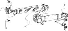
图2是本发明辅助微创外科手术的主从一体式机械臂整体结构示意图;Fig. 2 is a schematic diagram of the overall structure of the master-slave integrated mechanical arm for assisting minimally invasive surgery in the present invention;
图3、图4是本发明辅助微创外科手术的主从一体式机械臂的主操作端部分;Fig. 3 and Fig. 4 are the main operation end part of the master-slave integrated mechanical arm for assisting minimally invasive surgery in the present invention;
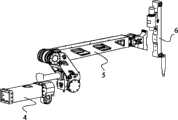
图5是本发明的辅助微创外科手术的主从一体式机械臂的从操作端部分;Fig. 5 is the slave operating end part of the master-slave integrated mechanical arm of the assisted minimally invasive surgery of the present invention;
图6是图5所示的从操作端部分的基座结构示意图;Fig. 6 is a schematic view of the structure of the base from the operating end part shown in Fig. 5;
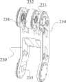
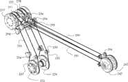
图7、8、9、10和11是图5所示的从操作端部分的主动机械臂部分的结构示意图;Figures 7, 8, 9, 10 and 11 are schematic structural views of the active mechanical arm part from the operating end part shown in Figure 5;
图12是图5所示的从操作端部分的伸缩部分结构示意图;Fig. 12 is a schematic structural diagram of the telescopic part of the slave operation end part shown in Fig. 5;
图13是图12所示的伸缩部分的传动机构的结构示意图;Fig. 13 is a structural schematic diagram of the transmission mechanism of the telescopic part shown in Fig. 12;
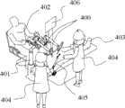
图14描述了基于本发明的机械臂的微创手术机器人系统总体示意图。Fig. 14 depicts an overall schematic diagram of a minimally invasive surgical robot system based on the robotic arm of the present invention.
具体实施方式Detailed ways
下面结合附图和具体实施例对本发明作以详细描述。The present invention will be described in detail below in conjunction with the accompanying drawings and specific embodiments.
如图1所示,为本发明的原理图,由主操作端600和从操作端601两大部分组成。主操作端关节I500和从操作端关节I501共线,与主操作端关节I500和从操作端关节I501垂直的主操作端关节II502和从操作端关节II503位于主操作端关节I500和从操作端关节I501的轴线所在的直线上。从操作端关节II503与其他6个旋转运动副构成双平行四边形机构,该机构使得手术工具轴线509在运动过程中始终通过一固定点510。这样,将主操作端600的关节运动信号直接传递至从操作端601控制其各关节运动,可使主操作端参考点505的运动方向与从操作端参考点I507的运动方向完全一致,504为主操作端参考点运动后的位置,506为从操作端参考点II运动后的位置。基于本原理的机器人在控制上不需要复杂的运动控制算法,有利于减少机器人的复杂程度,并降低系统的故障率。将从操作端601的平行四边形机构用丝传动方式实现,有利于减小系统的体积和重量,并可以降低系统加工制造难度,具体实现方式见后续说明。As shown in FIG. 1 , it is a principle diagram of the present invention, which is composed of two parts, the
图2所示为本发明的总体结构示意图,由主操作端1、从操作端2及工具夹持端3三部分组成。FIG. 2 is a schematic diagram of the overall structure of the present invention, which consists of three parts: the
图3、图4为本发明的主操作端I的示意图。所述的主操作端1包括其上设置有可旋转的主手关节I轴102的主手关节I座100,主手关节I轴102的输出端与其内设置有可旋转的主手关节II轴105的主手关节II座103相连,所述的主手关节I轴102和主手关节II轴105的轴线彼此垂直设置,传感器II01、II104的扭柄分别通过联轴器连接在主手关节I轴102及主手关节II轴105上。传感器I101、II104分别记录主手关节I轴102在主手关节I座100内及主手关节II轴105在主手关节II座103内的运动信息。在所述的主手关节II轴上固定有伸缩架106,所述的伸缩架106的底座与伸缩上座107的顶部固定相连;所述的伸缩上座107通过直线运动机构与伸缩下座108相连以使所述的伸缩下座108相对于伸缩上座107能够上下移动并通过传感器V121记录所述的上下移动,所述的伸缩下座108通过轴线沿竖直方向设置的转轴与一个自转座114转动相连,一个其轴线与所述的转轴轴线垂直设置的偏转轴116安装在所述的自转座114上,传感器III113和传感器IV115的扭柄分别通过联轴器连接在转轴、偏转轴116上,在所述的偏转轴116上连接有开合座118,开合座118上安装有开合瓣I124和开合瓣II125,开合瓣I124、开合瓣II125之间通过两个连接杆相连,所述的两个连接杆之间通过连接轴相连并且所述的连接轴插在连接在开合座上的直线传感器117的开槽中。开合瓣I124、开合瓣II125可在开合座118上实现开合运动,直线传感器117可用来记录该运动的信息。这样当医生对开合瓣I124、开合瓣II124进行操作时,主操作端1便可以记录医生的运动信息,并将该信息通过控制系统处理后传递至从操作端2和工具夹持端3,用以实现辅助手术操作。3 and 4 are schematic diagrams of the main operating terminal I of the present invention. The
所述的直线运动机构优选的包括安装在伸缩上座107上的共面且轴线彼此相交的上旋转轴I119和上旋转轴II120,上连杆I109的一端和上旋转轴I119转动相连,上连杆II110的一端和上旋转轴II120转动相连,上连杆I109的另一端和中间旋转轴I122转动相连,上连杆II110的另一端和中间旋转轴II123转动相连,下连杆I111的一端与中间旋转轴I122相连,中间旋转轴I122的轴线与上旋转轴I119轴线相平行,下连杆II112的一端与中间旋转轴II123相连,所述的中间旋转轴II123与上旋转轴II120轴线相平行,下连杆I111和下连杆II112的另一端分别通过安装在伸缩下座108上的下旋转轴I126、下旋转轴II127与伸缩下座108相连;下旋转轴I126的轴线和下旋转轴II127的轴线分别与上旋转轴I119的轴线和上旋转轴II120的轴线相平行设置,传感器V121的扭柄与上旋转轴II120通过联轴器相连。由伸缩上座107、上旋转轴I119、上旋转轴II120、上连杆I109、上连杆II110、中间旋转轴I122、中间旋转轴II123、下连杆I111、下连杆II112、伸缩下座108所构成的机构使得伸缩下座108相对于伸缩上座107仅存在一个靠近或远离的直线运动自由度;该运动方式也可由导轨-滑块机构或花键-外筒机构实现。由传感器V121的信息,可计算出伸缩下座108相对于伸缩上座107的运动信息。The linear motion mechanism preferably includes an upper rotation shaft I119 and an upper rotation shaft II120 installed on the telescopic
通过轴承安装于伸缩下座108上的自转座114可在伸缩下座108上旋转,传感器III113可用于记录该运动的信息;通过轴承安装与自转座114上的偏转轴116可在自转座114上运动,传感器IV115可用于记录该运动的信息。The
图5所示为本发明的从操作端2的示意图。从操作端2包括:一端与主操作端1相连的基座部分4,与基座部分4相连的主动机械臂部分5,以及安装于主动机械臂部分5上的伸缩部分6。FIG. 5 is a schematic diagram of the
图6所示为本发明从操作端2的基座部分4的示意图。基座部分4包含有基座210,基座210的一端与主操作端1的主手关节I座100相连,另一端固定连接有从手关节I座212,从手关节I座212上安装有从手关节I轴213,从手关节I轴213可在置于基座部分4内部的电机I211的驱动下旋转。从手关节I座212上设置有被动连接面214,通过被动连接面214可将本发明固定于被动调整架上,所述的被动调整架可采用已公开专利(如专利号:200610129845.6)的形式。FIG. 6 is a schematic view of the
图7-图13所示为本发明从操作端2的主动机械臂部分5的示意图。所述的主动机械臂部分5包含与从手关节I轴213的输出端固定相连的从手关节II座221,丝轮I223和丝轮II224对称的固定连接在从手关节II座221的两侧并且丝轮I223和丝轮II224的轴线沿与从手关节I轴213的输出轴轴线垂直的方向设置,其轴线L2沿与丝轮I223轴线相同方向设置的驱动轴II225安装于从手关节II座221上,其轴线L1沿与丝轮I223轴线垂直方向设置的驱动轴I227通过轴承安装于从手关节II座221上,所述的驱动轴I227通过联轴器与电机II226相连,传感器IV228的扭柄与驱动轴I相连;在所述的驱动轴I227和驱动轴II225之间连接有传动丝I229。驱动轴I227可在电机II226的驱动下旋转;连接两驱动轴的传动丝I229将从手关节II驱动轴I227的旋转运动转化为从手关节II的驱动轴II225的旋转运动。所述的驱动轴II225的两个输出端222分别与设置在从手连杆I230下端上的两个法兰面235固定相连,所述的从手连杆I230的上端有三个分支,其中中心孔内设置有轴承的丝轮III233和丝轮IV232固定连接于从手连杆I230的上端中间分支上,从手连杆I230的两侧分支上设置有与安装于丝轮III233和丝轮IV232上的轴承234同心的轴承231,固定连接于从手连杆II236一端的丝轮V237、丝轮VI238分别通过在其轴心设置的支撑轴239与轴承231、234相连,连杆II输出轴240通过轴承安装于从手连杆II236的另一端,丝轮VII242、丝轮VIII243固定连接于连杆II输出座241上,连杆II输出座241与连杆II输出轴240固定相连,传动丝II252和传动丝III253的一端分别固定于丝轮I223、丝轮II224的丝槽内,经系列导向轮254和张紧轮255传递后,另一端分别固定于丝轮V237和丝轮VI238的丝槽内,传动丝IV251和传动丝V250的一端分别固定于丝轮III233和丝轮IV232的丝槽内,经导向轮254和张紧轮255传递后,另一端分别固定于丝轮VII242和丝轮VIII243的丝槽内,从手伸缩座244与连杆II输出座241固定相连;在从手伸缩座244上设置有导轨247,在所述的导轨的上安装有滑块248,工具夹持端3与滑块248固定相连,所述的滑块248通过传动机构在所述的导轨247上滑动。7-13 are schematic diagrams of the active mechanical arm part 5 of the
优选的所述的传动机构包括电机III245,所述的电机III的输出轴与驱动丝轮246相连,在所述的驱动丝轮246上缠绕的传动丝的两端258、259分别通过伸缩导向轮256和伸缩支撑轮257与工具夹持端3的上下两端相连。工具夹持端3与滑块248固定相连,工具夹持端3便可以在电机III245和传动丝的牵引下沿导轨247运动。该部分运动如图13所示。电机III245牵引工具夹持端3的运动也可以由丝杠导轨机构实现。Preferably, the transmission mechanism includes a
工具夹持端3可采用专利(专利号:200710056701.7)的形式,其详细结构不属于本发明的范畴。The
图14描述了基于本发明的微创手术机器人系统的示意图。两个本发明的机械臂400安装于被动调整臂401上,内窥镜则安装在内镜臂405上,内镜臂可采用专利(专利号:200810152765.1)的形式。这样医生402在助手404的配合下,通过观察显示器406传来的病人403体内的手术场景信息,便可以利用本发明辅助对病人403进行微创手术操作。Fig. 14 depicts a schematic diagram of a minimally invasive surgical robot system based on the present invention. The two
下面说明本发明的辅助微创外科手术的主从一体式机械臂的动作实施过程。The action implementation process of the master-slave integrated mechanical arm for assisting minimally invasive surgery of the present invention will be described below.
当操作者对本发明辅助微创外科手术的主从一体式机械臂的主操作端进行操作时,主操作端各关节的传感器可记录各关节的运动变化信息。由于本发明的特点,主操作端参考点的运动与从操作端参考点的运动完全一致;因此,在控制器接收到主操作端的关节运动信息后,可直接将其传递至从操作端,控制从操作端电机控制各运动关节实时跟踪主操作端的运动,复现主操作端操作者对系统的输入动作。在本发明装置中操作者对主操作端进行操作时,若主操作端关节I的关节角度发生变化,则控制器所读取的传感器I101的值也会发生变化,控制器进而实时地控制电机I转动使从操作端关节I沿主操作端关节I的变化方向运动相同的角度。与此类似,若控制器检测到主操作端关节II的传感器II104的读数发生变化,则控制器会实时控制电机II转动使从操作端关节II沿与主操作端关节II的变化方向运动相同的角度。若控制器通过传感器V121检测到主操作端的直线运动机构发生运动,则控制器会控制从操作端电机III245牵引工具夹持端作出与主操作端的直线运动机构一致的运动,与主从操作端关节I、关节II的完全跟踪运动不同,主操作端的直线运动机构的运动量是按照一定的比例映射到从操作端的工具夹持端,比例系数一般不大于1。当然,本装置在使用过程中在安装手术工具末端的情况下还可以分别通过传感器III113、传感器IV115、直线传感器117检测主操作端的自转、偏转和开合量,然后将自转、偏转和开合量信号通过控制器传递给手术工具末端用以控制手术工具末端的自转、偏转和开合运动。When the operator operates the master operating end of the master-slave integrated mechanical arm for assisting minimally invasive surgery of the present invention, the sensors of each joint at the master operating end can record the movement change information of each joint. Due to the characteristics of the present invention, the motion of the reference point of the master operating end is exactly the same as the motion of the reference point of the slave operating end; The motor of the slave operation end controls each joint to track the movement of the main operation end in real time, and reproduces the input action of the operator on the main operation end to the system. When the operator operates the main operating end in the device of the present invention, if the joint angle of the main operating end joint I changes, the value of the sensor I101 read by the controller will also change, and the controller will then control the motor in real time. I rotation makes the joint I of the slave operating end move the same angle along the changing direction of the joint I of the master operating end. Similar to this, if the controller detects that the reading of the sensor II104 of the joint II of the main operation end changes, the controller will control the rotation of the motor II in real time so that the joint II of the slave operation end moves in the same direction as the joint II of the main operation end. angle. If the controller detects the movement of the linear motion mechanism at the master operating end through the sensor V121, the controller will control the motor III245 at the slave operating end to move the clamping end of the traction tool to make a movement consistent with the linear motion mechanism at the master operating end. I. The complete tracking motion of joint II is different. The movement amount of the linear motion mechanism at the master operating end is mapped to the tool clamping end at the slave operating end according to a certain ratio, and the proportional coefficient is generally not greater than 1. Of course, the device can also detect the rotation, deflection and opening and closing amount of the main operating end through the sensor III113, sensor IV115, and
Claims (3)
Priority Applications (1)
| Application Number | Priority Date | Filing Date | Title |
|---|---|---|---|
| CN2010102232537ACN101889900B (en) | 2010-07-12 | 2010-07-12 | Master-slave integrated mechanical arm for assisting minimally invasive surgery |
Applications Claiming Priority (1)
| Application Number | Priority Date | Filing Date | Title |
|---|---|---|---|
| CN2010102232537ACN101889900B (en) | 2010-07-12 | 2010-07-12 | Master-slave integrated mechanical arm for assisting minimally invasive surgery |
Publications (2)
| Publication Number | Publication Date |
|---|---|
| CN101889900A CN101889900A (en) | 2010-11-24 |
| CN101889900Btrue CN101889900B (en) | 2012-04-11 |
Family
ID=43099371
Family Applications (1)
| Application Number | Title | Priority Date | Filing Date |
|---|---|---|---|
| CN2010102232537AActiveCN101889900B (en) | 2010-07-12 | 2010-07-12 | Master-slave integrated mechanical arm for assisting minimally invasive surgery |
Country Status (1)
| Country | Link |
|---|---|
| CN (1) | CN101889900B (en) |
Families Citing this family (44)
| Publication number | Priority date | Publication date | Assignee | Title |
|---|---|---|---|---|
| CN102141133B (en)* | 2011-01-10 | 2013-03-20 | 天津大学 | Wire fixing mechanism for wire transmission system |
| CN102161198B (en)* | 2011-03-18 | 2012-09-19 | 浙江大学 | A Master-Slave Co-Evolution Method for Path Planning of Mobile Manipulators in 3D Space |
| CN102499731B (en)* | 2011-11-01 | 2013-11-06 | 西安交通大学 | All-dimensional automatic traction and support device of dragline type endoscopic surgical instrument |
| CN102697564B (en)* | 2012-06-20 | 2014-04-23 | 哈尔滨工业大学 | Flexible-arm robot for minimally invasive single-port abdominal surgery |
| CN103302656B (en)* | 2012-10-26 | 2015-09-23 | 青岛嘉龙自动化设备有限公司 | Manipulator and clamp method thereof |
| CN103006327B (en)* | 2012-12-03 | 2014-09-17 | 北京航空航天大学 | Master-slave teleoperation vascular intervention surgical robot |
| CN103252776B (en)* | 2013-05-22 | 2016-04-20 | 西南交通大学 | Robot tail end straight motion transmission device |
| CN106068175B (en)* | 2014-03-14 | 2020-04-28 | 索尼公司 | Robot arm device, robot arm control method, and program |
| CN104942825A (en)* | 2014-03-28 | 2015-09-30 | 鸿富锦精密工业(深圳)有限公司 | Mechanical arm |
| CN104942824A (en)* | 2014-03-28 | 2015-09-30 | 鸿富锦精密工业(深圳)有限公司 | Mechanical arm |
| CN104013471B (en)* | 2014-06-23 | 2016-08-24 | 苏州康多机器人有限公司 | A kind of one-piece type surgical operation robot system of principal and subordinate |
| CN106794103B (en)* | 2014-07-30 | 2020-11-03 | 欧达尔医疗系统有限责任公司 | Bushings, carrying arms and carrying systems for medical hanger devices |
| CN104224325B (en)* | 2014-10-11 | 2016-08-24 | 天津工业大学 | A kind of wire rope gearing linear telescopic mechanism for micro-wound operation robot |
| CN104224328B (en)* | 2014-10-11 | 2017-05-24 | 天津工业大学 | Robot body structure for supporting minimally-invasive surgery instrument |
| CN104523306B (en)* | 2015-01-05 | 2016-11-23 | 苏州康多机器人有限公司 | A kind of approximation telecentricity fixed point mechanism for Minimally Invasive Surgery operation |
| CN104546066B (en)* | 2015-01-22 | 2017-02-22 | 中国科学院深圳先进技术研究院 | Passive type nasal endoscopic surgery assisting robot |
| CN105057631B (en)* | 2015-08-11 | 2017-08-25 | 华南理工大学 | A kind of mechanical arm of the aluminium alloy compression casting with gradient network structure and its manufacture method |
| CN105147393B (en)* | 2015-08-19 | 2017-06-20 | 哈尔滨工业大学 | A kind of minimally invasive robot holds mirror mechanical arm |
| CN105012023A (en)* | 2015-08-19 | 2015-11-04 | 哈尔滨工业大学 | Instrument holding mechanical arm used for minimally-invasive robot |
| CN105286999B (en)* | 2015-10-15 | 2017-09-29 | 天津大学 | Minimally Invasive Surgery apparatus with end rotation function |
| CN105395254B (en)* | 2015-12-22 | 2018-03-30 | 哈尔滨工业大学 | A kind of control system of split type micro-wound operation robot |
| CN105748153B (en)* | 2016-05-24 | 2018-03-20 | 山东大学齐鲁医院 | A kind of assisted minimally invasive surgical operation robot mechanical arm |
| CN106037937B (en)* | 2016-07-08 | 2018-06-22 | 天津大学 | A kind of operating robot motion arm with adaptive ability |
| CN106137398A (en)* | 2016-07-29 | 2016-11-23 | 苏州高通机械科技有限公司 | A kind of spinal operation mechanical hand |
| CN106388937B (en)* | 2016-09-28 | 2018-12-18 | 西安交通大学 | A kind of adjustable Pneumatic flexible surgical procedure arm of multiple degrees of freedom rigidity |
| CN106691592B (en)* | 2016-11-23 | 2023-08-04 | 深圳市罗伯医疗科技有限公司 | Single-port abdominal cavity minimally invasive surgery robot arm |
| CN106618736B (en)* | 2016-12-16 | 2019-03-08 | 微创(上海)医疗机器人有限公司 | Mechanical arm and operating robot with double freedom |
| CN107157581B (en)* | 2017-04-06 | 2020-02-18 | 上海工程技术大学 | A decoupled four-degree-of-freedom telecentric mechanism for extracorporeal minimally invasive surgery |
| CN108210077B (en)* | 2018-01-02 | 2019-03-01 | 王中良 | Surgical instrument mounting assembly used in a kind of laparoscopic surgery |
| CN108814718B (en)* | 2018-03-23 | 2022-03-04 | 深圳市精锋医疗科技股份有限公司 | Operating arm |
| CN108338840A (en)* | 2018-04-17 | 2018-07-31 | 成都博恩思医学机器人有限公司 | A kind of laparoscopic surgery holds robot system with endoscope |
| CN108338841B (en)* | 2018-04-17 | 2021-03-23 | 成都博恩思医学机器人有限公司 | A mirror-holding robot system for laparoscopic surgery |
| CN108680149B (en)* | 2018-05-15 | 2019-05-24 | 中铁十二局集团第七工程有限公司 | A kind of Sopwith staff/prism bar is vertically from steady control device and control method |
| CN109124772A (en)* | 2018-06-25 | 2019-01-04 | 深圳市精锋医疗科技有限公司 | From operation equipment |
| GB2578791B (en)* | 2018-11-09 | 2022-08-17 | Cmr Surgical Ltd | Haptic control of a surgeon console |
| CN109431608A (en)* | 2018-11-15 | 2019-03-08 | 山东大学齐鲁医院 | A kind of nested type assisting minimally invasive single hole operating robot |
| CN110236677B (en)* | 2019-04-30 | 2024-04-30 | 汕头大学 | Parallelogram structure minimally invasive surgery mechanical arm |
| CN112353361B (en)* | 2020-09-21 | 2023-07-25 | 常州市速瑞医疗科技有限公司 | 3D pleuroperitoneal cavity system based on master-slave integrated intelligent mirror supporting robot |
| CN113081475B (en)* | 2021-04-22 | 2022-03-29 | 北京航空航天大学 | Master manipulator of master-slave type intraocular surgery robot |
| CN113662673B (en)* | 2021-08-25 | 2023-08-22 | 深圳市精锋医疗科技股份有限公司 | Mechanical arm, slave operation device and surgical robot |
| CN113729952A (en)* | 2021-10-12 | 2021-12-03 | 中南大学 | Actuator quick-change driving mechanism of surgical robot |
| CN115281588B (en)* | 2022-06-30 | 2023-02-03 | 中国科学院自动化研究所 | Flexible tail end controllable medical instrument motion control system and medical equipment |
| CN117842393B (en)* | 2023-12-05 | 2024-11-05 | 哈尔滨工业大学 | Transfer device with automatic switching of elongation and swing driving power |
| CN119587170A (en)* | 2024-11-22 | 2025-03-11 | 北京中科鸿泰医疗科技有限公司 | Interventional surgery robot control end rotation limit structure and method |
Citations (9)
| Publication number | Priority date | Publication date | Assignee | Title |
|---|---|---|---|---|
| US6364888B1 (en)* | 1996-09-09 | 2002-04-02 | Intuitive Surgical, Inc. | Alignment of master and slave in a minimally invasive surgical apparatus |
| US6786896B1 (en)* | 1997-09-19 | 2004-09-07 | Massachusetts Institute Of Technology | Robotic apparatus |
| CN1634685A (en)* | 2005-01-05 | 2005-07-06 | 天津大学 | Master Operator with Gripping Feel |
| CN1654174A (en)* | 2005-02-01 | 2005-08-17 | 天津大学 | Surgical robot from operator's hand |
| CN101193603A (en)* | 2005-06-06 | 2008-06-04 | 直观外科手术公司 | Laparoscopic ultrasound robotic surgical system |
| CN101421080A (en)* | 2006-02-03 | 2009-04-29 | 欧洲原子能共同体由欧洲委员会代表 | Medical robotic system with manipulator arm of the cylindrical coordinate type |
| CN101444431A (en)* | 2008-12-23 | 2009-06-03 | 天津大学 | Three dimensional force feedback main operator assisting minimally invasive surgery robot |
| CN101690674A (en)* | 2009-09-30 | 2010-04-07 | 哈尔滨工业大学 | Abdominal minimally invasive surgery instrument clamping manipulator |
| CN101732093A (en)* | 2009-11-30 | 2010-06-16 | 哈尔滨工业大学 | Micromanipulator for enterocoelia minimally invasive surgery |
- 2010
- 2010-07-12CNCN2010102232537Apatent/CN101889900B/enactiveActive
Patent Citations (9)
| Publication number | Priority date | Publication date | Assignee | Title |
|---|---|---|---|---|
| US6364888B1 (en)* | 1996-09-09 | 2002-04-02 | Intuitive Surgical, Inc. | Alignment of master and slave in a minimally invasive surgical apparatus |
| US6786896B1 (en)* | 1997-09-19 | 2004-09-07 | Massachusetts Institute Of Technology | Robotic apparatus |
| CN1634685A (en)* | 2005-01-05 | 2005-07-06 | 天津大学 | Master Operator with Gripping Feel |
| CN1654174A (en)* | 2005-02-01 | 2005-08-17 | 天津大学 | Surgical robot from operator's hand |
| CN101193603A (en)* | 2005-06-06 | 2008-06-04 | 直观外科手术公司 | Laparoscopic ultrasound robotic surgical system |
| CN101421080A (en)* | 2006-02-03 | 2009-04-29 | 欧洲原子能共同体由欧洲委员会代表 | Medical robotic system with manipulator arm of the cylindrical coordinate type |
| CN101444431A (en)* | 2008-12-23 | 2009-06-03 | 天津大学 | Three dimensional force feedback main operator assisting minimally invasive surgery robot |
| CN101690674A (en)* | 2009-09-30 | 2010-04-07 | 哈尔滨工业大学 | Abdominal minimally invasive surgery instrument clamping manipulator |
| CN101732093A (en)* | 2009-11-30 | 2010-06-16 | 哈尔滨工业大学 | Micromanipulator for enterocoelia minimally invasive surgery |
Non-Patent Citations (3)
| Title |
|---|
| 冯美等.腹腔微创手术机器人末端执行机构的设计和实现.《机器人》.2009,(第01期),* |
| 朴明波等.外科辅助手术机器人的发展及关键技术分析.《机械设计与制造》.2008,(第07期),* |
| 王淑敬等.腹腔镜微创外科手术主从式机器人从手结构设计.《组合机床与自动化加工技术》.2006,(第02期),* |
Also Published As
| Publication number | Publication date |
|---|---|
| CN101889900A (en) | 2010-11-24 |
Similar Documents
| Publication | Publication Date | Title |
|---|---|---|
| CN101889900B (en) | Master-slave integrated mechanical arm for assisting minimally invasive surgery | |
| US11969889B2 (en) | Lever actuated gimbal plate | |
| CN113015498B (en) | Decoupling the tool shaft from the cable driven load | |
| EP3556314B1 (en) | Robotic manipulator having two degrees of freedom and surgical robot | |
| CN101637402B (en) | Minimally invasive surgical wire driving and four-freedom surgical tool | |
| US10219871B2 (en) | Robotic system for tele-surgery | |
| CN107184275A (en) | A kind of robot for being used to aid in splanchnocoel Minimally Invasive Surgery | |
| EP3556520B1 (en) | Remote-center-of-motion mechanism | |
| CN101261781B (en) | Five degrees of freedom force feedback virtual surgical instrument | |
| CN101444431B (en) | Three-dimensional force feedback master manipulator of assisted minimally invasive surgical robot | |
| Gu et al. | A compliant transoral surgical robotic system based on a parallel flexible mechanism | |
| CN102499757B (en) | Nine-degree-of-freedom minimally invasive surgical robot main manipulator with force feedback | |
| De Donno et al. | Introducing STRAS: A new flexible robotic system for minimally invasive surgery | |
| CN101411632B (en) | A robotic active stent for assisting minimally invasive surgery | |
| CN105748153B (en) | A kind of assisted minimally invasive surgical operation robot mechanical arm | |
| CN104799891A (en) | Instrument for robot-assisted micro-invasive surgery | |
| CN104546144A (en) | Switchable seven-degree-of-freedom force feedback remote operating manipulator | |
| CN101396298A (en) | Robot system with endoscope for assisting micro-wound surgical operation | |
| CN109009453A (en) | Intervene the force feedback type main manipulator of robot | |
| CN108888347A (en) | Intervene Robot Force-Feedback type main manipulator | |
| US11844584B2 (en) | Robotic system for tele-surgery | |
| CN207708011U (en) | A kind of parallel Three Degree Of Freedom remote centre of motion operating robot | |
| CN111407407A (en) | A three-degree-of-freedom series-parallel telecentric mechanism | |
| CN204428164U (en) | A kind of seven freedom force feedback remote operating hands of switchable type | |
| CN107049498A (en) | A kind of parallel Three Degree Of Freedom remote centre of motion operating robot |
Legal Events
| Date | Code | Title | Description |
|---|---|---|---|
| C06 | Publication | ||
| PB01 | Publication | ||
| C10 | Entry into substantive examination | ||
| SE01 | Entry into force of request for substantive examination | ||
| C14 | Grant of patent or utility model | ||
| GR01 | Patent grant | ||
| TR01 | Transfer of patent right | Effective date of registration:20220831 Address after:264211 no.566-1 Qishan Road, caomiaozi Town, Lingang Economic and Technological Development Zone, Weihai City, Shandong Province Patentee after:SHANDONG WEIGAO OPERATION ROBOT CO.,LTD. Address before:300072 Tianjin City, Nankai District Wei Jin Road No. 92 Patentee before:Tianjin University Patentee before:Tianjin University Asset Management Co.,Ltd. Effective date of registration:20220831 Address after:300072 Tianjin City, Nankai District Wei Jin Road No. 92 Patentee after:Tianjin University Patentee after:Tianjin University Asset Management Co.,Ltd. Address before:300072 Tianjin City, Nankai District Wei Jin Road No. 92 Patentee before:Tianjin University | |
| TR01 | Transfer of patent right |