CN101887202B - M-Z type spectra shaper for optical fiber sensing - Google Patents
M-Z type spectra shaper for optical fiber sensingDownload PDFInfo
- Publication number
- CN101887202B CN101887202BCN2010102065905ACN201010206590ACN101887202BCN 101887202 BCN101887202 BCN 101887202BCN 2010102065905 ACN2010102065905 ACN 2010102065905ACN 201010206590 ACN201010206590 ACN 201010206590ACN 101887202 BCN101887202 BCN 101887202B
- Authority
- CN
- China
- Prior art keywords
- arm
- coupler
- output
- input
- interference
- Prior art date
- Legal status (The legal status is an assumption and is not a legal conclusion. Google has not performed a legal analysis and makes no representation as to the accuracy of the status listed.)
- Expired - Fee Related
Links
- 238000001228spectrumMethods0.000titleclaimsabstractdescription27
- 239000013307optical fiberSubstances0.000titleclaimsabstractdescription17
- 230000008878couplingEffects0.000claimsdescription62
- 238000010168coupling processMethods0.000claimsdescription62
- 238000005859coupling reactionMethods0.000claimsdescription62
- 239000000835fiberSubstances0.000claimsdescription20
- 230000003287optical effectEffects0.000claimsdescription10
- 230000003595spectral effectEffects0.000claimsdescription8
- 230000005540biological transmissionEffects0.000claimsdescription3
- 238000005253claddingMethods0.000claimsdescription3
- 230000004927fusionEffects0.000claims3
- 238000007493shaping processMethods0.000abstractdescription4
- 230000007246mechanismEffects0.000description47
- 238000002844meltingMethods0.000description9
- 230000008018meltingEffects0.000description9
- 239000011159matrix materialSubstances0.000description4
- 238000004891communicationMethods0.000description2
- 238000005516engineering processMethods0.000description2
- 230000008676importEffects0.000description2
- 238000000034methodMethods0.000description2
- 230000009286beneficial effectEffects0.000description1
- 230000008901benefitEffects0.000description1
- 238000006243chemical reactionMethods0.000description1
- 230000001427coherent effectEffects0.000description1
- 238000010586diagramMethods0.000description1
- 238000001914filtrationMethods0.000description1
- 230000005855radiationEffects0.000description1
- 230000004044responseEffects0.000description1
- 230000035939shockEffects0.000description1
- 239000007787solidSubstances0.000description1
- 230000002269spontaneous effectEffects0.000description1
Images


Landscapes
- Optical Couplings Of Light Guides (AREA)
- Optical Modulation, Optical Deflection, Nonlinear Optics, Optical Demodulation, Optical Logic Elements (AREA)
Abstract
Description
Technical field
The present invention relates to light spectrum reshaping and sensing technology, particularly relate to a kind of M-Z type spectra shaper for optical fiber sensing.
Background technology
Have all solid state, miniaturization, shock resistance, anti-interference, advantage such as precision is high, the life-span is long and develop optical fibre gyro rapidly and be to use the better ASE light source of the higher spectrum stability of power to one of important means of more high precision development; But the ASE light source can not satisfy the requirement that optical fibre gyro is used on spectral pattern; Because optical fibre gyro is that to utilize the wide range light wave be that the interference of white light is carried out angular speed and surveyed, need Gauss or type Gauss's spectral pattern to reach spectrum coherence function value and reduce rapidly and to keep low value and adopt and to reduce coherent noise.Communication is at present amplified the spectrum that sends with the ASE light source through the spontaneous radiation of erbium-doped fiber and is bordering on rectangle through smooth filtering spectral pattern, and such ASE light source will be used next conversion that just must type of carrying out rectangle type of composing Gauss type spectrum in the gyro, is light spectrum reshaping.Present existing light spectrum reshaping method implements more complicated, cost is higher or increase the light source volume greatly; Can't be applied in the high-precision sensing field of optical fibre gyro; So need a kind of simply and effectively device to accomplish the shaping of ASE light source spectral pattern, to reach the requirement that high-precision optical fiber gyro is used.
Summary of the invention
Use the ASE light source light spectrum to compose to present communication as the class rectangle; Do not satisfy class Gauss that optical fibre gyro requires and compose and have now shortcomings such as light spectrum reshaping method complex structure, volume are big, cost height; The object of the present invention is to provide a kind of M-Z type spectra shaper for optical fiber sensing; Effectively realize the shaping of ASE light source class rectangle type of composing Gauss spectrum, adapted to the needs of high-precision optical fiber gyro development.
The technical scheme that the present invention adopts is:
The present invention includes first coupling mechanism, phase-modulator and second coupling mechanism; The first input arm links to each other with the first input arm of first coupling mechanism; The second input arm links to each other with the second input arm of first coupling mechanism; First output arm of first coupling mechanism and first interferes an end of arm to link to each other, and second output arm of first coupling mechanism and second interferes an end of arm to link to each other; First interferes the other end of arm to link to each other with the first input arm of second coupling mechanism; Second interferes the other end of arm to link to each other with the second input arm of second coupling mechanism; First output arm of second coupling mechanism links to each other with first output arm, and second output arm of second coupling mechanism links to each other with second output arm; Phase-modulator is positioned at first and interferes arm one side, phase-modulator be electrooptic modulator or hot photomodulator or acousto-optic modulator or other can regulate first interfere the arm phase place optical waveguide modulator; Incident light inputs to first of first coupling mechanism by the first input arm and imports arm, and emergent light is exported respectively by first output arm and second output arm.
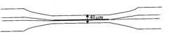
Described first coupling mechanism is identical with second coupler structure; Adopt healthy and free from worry SMF-28 fiber fuse to draw awl to form; The geometry of single melting cone fiber is: on the conical region xsect, be parabola shaped; At coupling regime linearly, the coupling regime cladding diameter is 40 μ m, and coupling regime length is 2000 μ m; Described first coupling mechanism and second coupling mechanism are merged by above-mentioned two melting cone fibers and form, and parallel melting cone fiber is overlapped forms by two for coupling regime, and the centre distance of two melting cone fiber fibre cores is 22 μ m.
Light is the light path big 9 μ ms of light path ratio in the second interference arm in the said first interference arm in transmission course; Optical path difference is produced by phase-modulator; The first interference arm and second that the phase-modulator modulation produces interferes the phase difference φ and first of arm to interfere arm and second to interfere the relation of the optical path difference Δ L of arm to be: Δ φ=2 π n Δ L/ λ; N is a fiber core refractive index in the formula, and λ is a lambda1-wavelength.
The beneficial effect that the present invention has is:
Volume of the present invention is little, and the nearly 100nm of three dB bandwidth has effectively realized the shaping of ASE light source class rectangle type of composing Gauss spectrum, has adapted to the needs of high-precision optical fiber gyro development.
Description of drawings
Fig. 1 is said M-Z type ASE light source light spectrum reshaper synoptic diagram.
Fig. 2 is single melting cone fiber geometry figure.
Fig. 3 is first coupling mechanism, the second coupler structure figure.
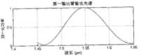
Fig. 4 is the output spectrum figure of first output arm.
Among the figure: 1-1, the first input arm, 1-2, the second input arm, 2, first coupling mechanism, the first input arm of 2-1, first coupling mechanism; The second input arm of 2-2, first coupling mechanism, first output arm of 2-3, first coupling mechanism, second output arm of 2-4, first coupling mechanism, 3-1, first interferes arm; 3-2, second interferes arm, and 4, phase-modulator, 5, second coupling mechanism, the first input arm of 5-1, second coupling mechanism; The second input arm of 5-2, second coupling mechanism, first output arm of 5-3, second coupling mechanism, second output arm of 5-4, second coupling mechanism; 6-1, first output arm, 6-2, second output arm;
Embodiment
Below in conjunction with accompanying drawing and embodiment the present invention is described further.
As shown in Figure 1, the present invention includesfirst coupling mechanism 2,modulator 4 andsecond coupling mechanism 5; The first input arm 1-1 links to each other with the first input arm 2-1 offirst coupling mechanism 2; The second input arm 1-2 links to each other with the second input arm 2-2 offirst coupling mechanism 2; The first output arm 2-3 offirst coupling mechanism 2 and first interferes the end of arm 3-1 to link to each other, and the second output arm 2-4 offirst coupling mechanism 2 and second interferes the end of arm 3-2 to link to each other; First interferes the other end of arm 3-1 to link to each other with the first input arm 5-1 ofsecond coupling mechanism 5; Second interferes the other end of arm 3-2 to link to each other with the second input arm 5-2 ofsecond coupling mechanism 5; The first output arm 5-3 ofsecond coupling mechanism 5 links to each other with the first output arm 6-1, and the second output arm 5-4 ofsecond coupling mechanism 5 links to each other with the second output arm 6-2; The phase-modulator 4 that produces optical path difference is positioned at first and interferes arm 3-1 one side, phase-modulator 4 for electrooptic modulator or hot photomodulator or acousto-optic modulator or other can regulate first interfere arm 3-1 phase place optical waveguide modulator; Incident light inputs to first offirst coupling mechanism 2 by the first input arm 1-1 and imports arm 2-1, and emergent light is exported respectively by the first output arm 6-1 and the second output arm 6-2.
Like Fig. 2, shown in Figure 3; Describedfirst coupling mechanism 2 is identical with second coupling mechanism, 5 structures; Adopt healthy and free from worry SMF-28 fiber fuse to draw awl to form, the geometry of single melting cone fiber is: on the conical region xsect, be parabola shaped, at coupling regime linearly; The coupling regime cladding diameter is 40 μ m, and coupling regime length is 2000 μ m; Describedfirst coupling mechanism 2 andsecond coupling mechanism 5 are merged by above-mentioned two melting cone fibers and form, and parallel melting cone fiber is overlapped forms by two for coupling regime, and the centre distance of two melting cone fiber fibre cores is 22 μ m.
Light is the light path big 9 μ ms of light path ratio in the second interference arm 3-2 in the said first interference arm 3-1 in transmission course; Optical path difference is produced by phase-modulator 4; The first interference arm 3-1 and second that phase-modulator 4 systems of transferring produce interferes the phase difference φ and first of arm 3-2 to interfere arm 3-1 and second to interfere the relation of the optical path difference Δ L of arm 3-2 to be: Δ φ=2 π n Δ L/ λ; N is a fiber core refractive index in the formula, and λ is a lambda1-wavelength.
The present invention can adopt Jones matrix to describe the response of each device to light wave fields, and the Jones matrix of saidfirst coupling mechanism 2,second coupling mechanism 5 is:
In the following formula, ki(i=1,2) is the amplitude coupling ratio offirst coupling mechanism 2,second coupling mechanism 5, ki(i=1,2) changes with lambda1-wavelength.Said first interferes arm 3-1 and second to interfere the Jones matrix of arm 3-2 to be:
N is a fiber core refractive index in the following formula, and λ is a lambda1-wavelength, and Δ L is the optical path difference that the first interference arm 3-1 and second interferes arm 3-2.The Jones matrix of said M-Z type spectra shaper for optical fiber sensing is:
J=C2*T*C1 (3)
Incident light is inputed to the first input arm 2-1 of first coupling mechanism by the first input arm 1-1; Incident light is a wide range light; The amplitude coupling ratio of the amplitude coupling ratio offirst coupling mechanism 2 andsecond coupling mechanism 5 changes with the variation of lambda1-wavelength; Emergent light is exported respectively by the first output arm 6-1 and the second output arm 6-2, and the output spectrum of the first output arm 6-1 is as shown in Figure 4: it is 1.55 μ m that gained class Gauss composes centre wavelength, the nearly 100nm of three dB bandwidth.
Claims (1)
Translated fromChinesePriority Applications (1)
| Application Number | Priority Date | Filing Date | Title |
|---|---|---|---|
| CN2010102065905ACN101887202B (en) | 2010-06-22 | 2010-06-22 | M-Z type spectra shaper for optical fiber sensing |
Applications Claiming Priority (1)
| Application Number | Priority Date | Filing Date | Title |
|---|---|---|---|
| CN2010102065905ACN101887202B (en) | 2010-06-22 | 2010-06-22 | M-Z type spectra shaper for optical fiber sensing |
Publications (2)
| Publication Number | Publication Date |
|---|---|
| CN101887202A CN101887202A (en) | 2010-11-17 |
| CN101887202Btrue CN101887202B (en) | 2012-08-29 |
Family
ID=43073174
Family Applications (1)
| Application Number | Title | Priority Date | Filing Date |
|---|---|---|---|
| CN2010102065905AExpired - Fee RelatedCN101887202B (en) | 2010-06-22 | 2010-06-22 | M-Z type spectra shaper for optical fiber sensing |
Country Status (1)
| Country | Link |
|---|---|
| CN (1) | CN101887202B (en) |
Families Citing this family (5)
| Publication number | Priority date | Publication date | Assignee | Title |
|---|---|---|---|---|
| CN103267999B (en)* | 2013-06-01 | 2018-02-06 | 青岛农业大学 | Mach-Zehnder interferometer based on dumb-bell shape optical fiber structure |
| CN103308082A (en)* | 2013-06-24 | 2013-09-18 | 哈尔滨工业大学 | Sensing structure of single ring embedded resonant cavity coupling M-Z interferometer |
| CN103487889A (en)* | 2013-08-12 | 2014-01-01 | 上海交通大学 | Mach-Zehnder optical switch structure based on coupling of double resonant cavities |
| CN105203135B (en)* | 2015-10-21 | 2017-08-25 | 哈尔滨工业大学 | A kind of high-sensitivity resonance system based on straight wave guide feedback wave lead ring straight wave guide |
| CN109586794B (en)* | 2018-11-16 | 2021-08-31 | 武汉光迅科技股份有限公司 | Double MZI multi-level PAM signal all-optical shaper and design method thereof |
Citations (2)
| Publication number | Priority date | Publication date | Assignee | Title |
|---|---|---|---|---|
| CN1383007A (en)* | 2002-06-17 | 2002-12-04 | 北京大学 | Dispersion compensator based on chirp waveguide raster |
| CN1623085A (en)* | 2002-01-24 | 2005-06-01 | 通用医疗公司 | Apparatus and method for ranging and noise reduction of low coherence interferometry (LCI) and optical coherence tomography (OCT) signals using parallel detection of spectral bands |
- 2010
- 2010-06-22CNCN2010102065905Apatent/CN101887202B/ennot_activeExpired - Fee Related
Patent Citations (2)
| Publication number | Priority date | Publication date | Assignee | Title |
|---|---|---|---|---|
| CN1623085A (en)* | 2002-01-24 | 2005-06-01 | 通用医疗公司 | Apparatus and method for ranging and noise reduction of low coherence interferometry (LCI) and optical coherence tomography (OCT) signals using parallel detection of spectral bands |
| CN1383007A (en)* | 2002-06-17 | 2002-12-04 | 北京大学 | Dispersion compensator based on chirp waveguide raster |
Non-Patent Citations (1)
| Title |
|---|
| 宫兆涛等.光纤陀螺用SLD 光源全数字控制系统.《仪器仪表学报》.2005,第26卷(第7期),689-691,695,714.* |
Also Published As
| Publication number | Publication date |
|---|---|
| CN101887202A (en) | 2010-11-17 |
Similar Documents
| Publication | Publication Date | Title |
|---|---|---|
| CN101464539B (en) | Mach-Zehnder interferometer based on coaxial optical fiber | |
| CN103975263B (en) | Fiber optic combiner and employ the device of this fiber optic combiner | |
| CN101887202B (en) | M-Z type spectra shaper for optical fiber sensing | |
| CN109581598B (en) | A coaxial dual waveguide fiber optic connector | |
| CN101604048B (en) | An all-fiber filter based on thin-core fiber | |
| CN101387519A (en) | A hollow-core photonic crystal fiber optic gyroscope | |
| CN202617124U (en) | Interference apparatus having the functions of optical signal dispersion compensation and phase compensation | |
| CN110768094A (en) | A mode-locked fiber laser based on a tapered multimode fiber saturable absorber | |
| CN105928549B (en) | More physical quantity Active Optical Fiber sensors and method for sensing based on cascade less fundamental mode optical fibre | |
| CN108089267B (en) | A fiber optic broadband optical vortex converter | |
| CN101458363B (en) | Coaxial fiber-based Michelson interferometer | |
| CN102207638A (en) | Squeeze-type asymmetrical double-core optical fiber switch | |
| CN108594364B (en) | Ultra wide bandwidth 3dB based on narrow slit wave-guide divides bundling device and method | |
| CN113866872A (en) | Mode controller of multi-core optical fiber to few-mode optical fiber | |
| CN202837591U (en) | Diaphragm type optical fiber laser coupler | |
| CN101846492A (en) | Interferometer combined by double F-P chambers and Mach-Zehnder | |
| CN108152879B (en) | A kind of multi-core fiber with controllable crosstalk | |
| US11054577B1 (en) | Hybrid fiber coupler and manufacturing method thereof | |
| CN116594202A (en) | An all-optical phase modulation device and modulation method based on MXene Ti3C2Tx/PDMS | |
| CN103368069A (en) | A laser device structure for reducing high-order mode | |
| CN113866869A (en) | Mode controller from multi-core fiber to ring-core fiber | |
| CN110824728A (en) | Dual-solid-core fiber photothermal phase modulator coated with thermosensitive material | |
| CN102809783B (en) | Diaphragm type fiber laser coupler | |
| CN205539566U (en) | Optical fibre mode converter | |
| CN210742553U (en) | Optical fiber core residual laser processing structure |
Legal Events
| Date | Code | Title | Description |
|---|---|---|---|
| C06 | Publication | ||
| PB01 | Publication | ||
| C10 | Entry into substantive examination | ||
| SE01 | Entry into force of request for substantive examination | ||
| C53 | Correction of patent for invention or patent application | ||
| CB03 | Change of inventor or designer information | Inventor after:Dai Hao Inventor after:Wang Dongyun Inventor after:She Xuan Inventor after:Shu Xiaowu Inventor after:Liu Cheng Inventor after:Che Shuangliang Inventor before:Wang Dongyun Inventor before:She Xuan Inventor before:Shu Xiaowu Inventor before:Liu Cheng Inventor before:Che Shuangliang | |
| COR | Change of bibliographic data | Free format text:CORRECT: INVENTOR; FROM: WANG DONGYUN SHE XUAN SHU XIAOWU LIU CHENG CHE SHUANGLIANG TO: DAI HAO WANG DONGYUN SHE XUAN SHU XIAOWU LIU CHENG CHE SHUANGLIANG | |
| C14 | Grant of patent or utility model | ||
| GR01 | Patent grant | ||
| CF01 | Termination of patent right due to non-payment of annual fee | Granted publication date:20120829 Termination date:20140622 | |
| EXPY | Termination of patent right or utility model |