CN101883625B - Static mixer for the exhaust system of an engine-driven vehicle, in particular a motor vehicle - Google Patents
Static mixer for the exhaust system of an engine-driven vehicle, in particular a motor vehicleDownload PDFInfo
- Publication number
- CN101883625B CN101883625BCN2008801186000ACN200880118600ACN101883625BCN 101883625 BCN101883625 BCN 101883625BCN 2008801186000 ACN2008801186000 ACN 2008801186000ACN 200880118600 ACN200880118600 ACN 200880118600ACN 101883625 BCN101883625 BCN 101883625B
- Authority
- CN
- China
- Prior art keywords
- lath
- maintenance
- static mixer
- blender
- mixer according
- Prior art date
- Legal status (The legal status is an assumption and is not a legal conclusion. Google has not performed a legal analysis and makes no representation as to the accuracy of the status listed.)
- Expired - Fee Related
Links
Images


Classifications
- B—PERFORMING OPERATIONS; TRANSPORTING
- B01—PHYSICAL OR CHEMICAL PROCESSES OR APPARATUS IN GENERAL
- B01D—SEPARATION
- B01D53/00—Separation of gases or vapours; Recovering vapours of volatile solvents from gases; Chemical or biological purification of waste gases, e.g. engine exhaust gases, smoke, fumes, flue gases, aerosols
- B01D53/34—Chemical or biological purification of waste gases
- B01D53/92—Chemical or biological purification of waste gases of engine exhaust gases
- B01D53/94—Chemical or biological purification of waste gases of engine exhaust gases by catalytic processes
- B01D53/9404—Removing only nitrogen compounds
- B01D53/9409—Nitrogen oxides
- B01D53/9431—Processes characterised by a specific device
- B—PERFORMING OPERATIONS; TRANSPORTING
- B01—PHYSICAL OR CHEMICAL PROCESSES OR APPARATUS IN GENERAL
- B01F—MIXING, e.g. DISSOLVING, EMULSIFYING OR DISPERSING
- B01F23/00—Mixing according to the phases to be mixed, e.g. dispersing or emulsifying
- B01F23/20—Mixing gases with liquids
- B01F23/21—Mixing gases with liquids by introducing liquids into gaseous media
- B01F23/213—Mixing gases with liquids by introducing liquids into gaseous media by spraying or atomising of the liquids
- B—PERFORMING OPERATIONS; TRANSPORTING
- B01—PHYSICAL OR CHEMICAL PROCESSES OR APPARATUS IN GENERAL
- B01F—MIXING, e.g. DISSOLVING, EMULSIFYING OR DISPERSING
- B01F25/00—Flow mixers; Mixers for falling materials, e.g. solid particles
- B01F25/40—Static mixers
- B01F25/42—Static mixers in which the mixing is affected by moving the components jointly in changing directions, e.g. in tubes provided with baffles or obstructions
- B01F25/43—Mixing tubes, e.g. wherein the material is moved in a radial or partly reversed direction
- B01F25/431—Straight mixing tubes with baffles or obstructions that do not cause substantial pressure drop; Baffles therefor
- B01F25/4315—Straight mixing tubes with baffles or obstructions that do not cause substantial pressure drop; Baffles therefor the baffles being deformed flat pieces of material
- F—MECHANICAL ENGINEERING; LIGHTING; HEATING; WEAPONS; BLASTING
- F01—MACHINES OR ENGINES IN GENERAL; ENGINE PLANTS IN GENERAL; STEAM ENGINES
- F01N—GAS-FLOW SILENCERS OR EXHAUST APPARATUS FOR MACHINES OR ENGINES IN GENERAL; GAS-FLOW SILENCERS OR EXHAUST APPARATUS FOR INTERNAL-COMBUSTION ENGINES
- F01N3/00—Exhaust or silencing apparatus having means for purifying, rendering innocuous, or otherwise treating exhaust
- F01N3/08—Exhaust or silencing apparatus having means for purifying, rendering innocuous, or otherwise treating exhaust for rendering innocuous
- F01N3/10—Exhaust or silencing apparatus having means for purifying, rendering innocuous, or otherwise treating exhaust for rendering innocuous by thermal or catalytic conversion of noxious components of exhaust
- F01N3/24—Exhaust or silencing apparatus having means for purifying, rendering innocuous, or otherwise treating exhaust for rendering innocuous by thermal or catalytic conversion of noxious components of exhaust characterised by constructional aspects of converting apparatus
- F01N3/28—Construction of catalytic reactors
- F01N3/2892—Exhaust flow directors or the like, e.g. upstream of catalytic device
- F—MECHANICAL ENGINEERING; LIGHTING; HEATING; WEAPONS; BLASTING
- F01—MACHINES OR ENGINES IN GENERAL; ENGINE PLANTS IN GENERAL; STEAM ENGINES
- F01N—GAS-FLOW SILENCERS OR EXHAUST APPARATUS FOR MACHINES OR ENGINES IN GENERAL; GAS-FLOW SILENCERS OR EXHAUST APPARATUS FOR INTERNAL-COMBUSTION ENGINES
- F01N2240/00—Combination or association of two or more different exhaust treating devices, or of at least one such device with an auxiliary device, not covered by indexing codes F01N2230/00 or F01N2250/00, one of the devices being
- F01N2240/20—Combination or association of two or more different exhaust treating devices, or of at least one such device with an auxiliary device, not covered by indexing codes F01N2230/00 or F01N2250/00, one of the devices being a flow director or deflector
- Y—GENERAL TAGGING OF NEW TECHNOLOGICAL DEVELOPMENTS; GENERAL TAGGING OF CROSS-SECTIONAL TECHNOLOGIES SPANNING OVER SEVERAL SECTIONS OF THE IPC; TECHNICAL SUBJECTS COVERED BY FORMER USPC CROSS-REFERENCE ART COLLECTIONS [XRACs] AND DIGESTS
- Y02—TECHNOLOGIES OR APPLICATIONS FOR MITIGATION OR ADAPTATION AGAINST CLIMATE CHANGE
- Y02A—TECHNOLOGIES FOR ADAPTATION TO CLIMATE CHANGE
- Y02A50/00—TECHNOLOGIES FOR ADAPTATION TO CLIMATE CHANGE in human health protection, e.g. against extreme weather
- Y02A50/20—Air quality improvement or preservation, e.g. vehicle emission control or emission reduction by using catalytic converters
Landscapes
- Chemical & Material Sciences (AREA)
- Engineering & Computer Science (AREA)
- Chemical Kinetics & Catalysis (AREA)
- Combustion & Propulsion (AREA)
- Health & Medical Sciences (AREA)
- Mechanical Engineering (AREA)
- Toxicology (AREA)
- General Engineering & Computer Science (AREA)
- Biomedical Technology (AREA)
- Environmental & Geological Engineering (AREA)
- Analytical Chemistry (AREA)
- General Chemical & Material Sciences (AREA)
- Oil, Petroleum & Natural Gas (AREA)
- Dispersion Chemistry (AREA)
- Exhaust Gas After Treatment (AREA)
Abstract
Description
Translated fromChinese技术领域technical field
本发明涉及一种根据权利要求1的前序部分所述的、用于由发动机驱动的车辆、特别是机动车的排气系统的静态混合器。The invention relates to a static mixer for an exhaust system of an engine-driven vehicle, in particular a motor vehicle, according to the preamble of claim 1 .
背景技术Background technique
通常已知,在用于降低氮氧化物排放的排气净化系统中,使用所谓的选择性催化还原(SCR),其中NOx转化在稀薄环境中通过专门匹配的催化转换器来实现。在此,为了进行NOx还原,将适合的还原剂加入排气流中,以便获得最终产物如N2、CO2和H2O。在活性的SCR-催化转化器中,例如使用氨或尿素作为还原剂。为了使还原剂与排气相混合,通常使用静态混合器,借助所述静态混合器要实现还原剂在排气流中的希望的分布用以有效地净化排气。It is generally known to use so-called selective catalytic reduction (SCR) in exhaust gas purification systems for reducing nitrogen oxide emissions, in which theNOx conversion takes place in a lean environment by means of specially adapted catalytic converters. Here, for NOx reduction, suitable reducing agents are added to the exhaust gas stream in order to obtain end products such as N2 , CO2 and H2 O. In active SCR catalytic converters, for example, ammonia or urea are used as reducing agents. For mixing the reducing agent with the exhaust gas, static mixers are usually used, by means of which a desired distribution of the reducing agent in the exhaust gas flow is to be achieved for efficient purification of the exhaust gas.
从US 5,489,153中已知这种用于流动通路的静态混合器,所述静态混合器在流动通路中具有多个所谓的转向件。所述转向件在此成排地设置在直角/矩形的支承格栅上。借助这种静态混合器,到达的流动能由转向件沿不同方向转向,其中转向件在各支承格栅开口中产生相对于主流动方向的横向流动。由此能通过涡流、特别是通过形成漩涡实现特别有效的混合。与这种具有直角格栅结构的静态混合器相关联的问题在于:在排气温度非常高时和/或在温度以较大的梯度变化时,在混合器的支承格栅区域中可能会出现裂纹和损坏。Such a static mixer for a flow path is known from US 5,489,153, which has a plurality of so-called deflectors in the flow path. The deflector elements are here arranged in rows on a rectangular/rectangular support grid. With the aid of such a static mixer, the incoming flow can be deflected in different directions by deflectors, wherein the deflectors produce a flow transverse to the main flow direction in the respective support grid opening. Particularly effective mixing can thus be achieved by vortexing, in particular by vortex formation. The problem associated with such static mixers with a right-angle grid structure is that at very high exhaust gas temperatures and/or when the temperature changes with large gradients, in the region of the support grid of the mixer can occur cracked and damaged.
发明内容Contents of the invention
因此,本发明的目的在于,提供一种静态混合器,该静态混合器用于由发动机驱动的车辆、特别是机动车的排气系统,借助所述静态混合器能以构造简单且功能可靠的方式降低混合器损坏的危险。It is therefore the object of the present invention to provide a static mixer for the exhaust system of an engine-driven vehicle, in particular a motor vehicle, by means of which a static mixer can be constructed in a simple and functionally reliable manner Reduced risk of mixer damage.
所述目的通过权利要求1的特征来实现。This object is achieved by the features of claim 1 .
根据权利要求1,至少一个保持板条至少在部分区域中设计成弹簧弹性的(federelastisch)和/或弹性地支承在混合器平面中。利用这种设计,能以构造和制造技术简单的方式避免由于材料膨胀所引起的、与温度有关的应力,进而避免损坏混合器,因为弹簧弹性的保持板条区域能可逆地补偿所述膨胀。According to claim 1 , at least one retaining strip is designed to be spring-elastic at least in partial regions and/or elastically mounted in the mixer plane. With this design, temperature-dependent stresses due to material expansion and thus damage to the mixer can be avoided in a structurally and production-technically simple manner, since the spring-elastic retaining web region can reversibly compensate for said expansion.
优选地,在此为了形成所述弹簧弹性的区域,至少一个保持板条在预定的保持板条区域中构造成弯曲的,特别是所述弯曲区域分别通过呈S曲线形弯曲的保持板条区域(S型)形成。利用这种弯曲的保持板条有利地避免如现有技术中那样的直角格栅布置结构。如本发明试验所证明的,特别是能利用保持板条或各保持板条区域的曲线型弯曲的设计来构造混合器,利用所述混合器特别是当排气温度高时能明显地降低弹性膨胀补偿,进而降低损坏静态混合器的危险。Preferably, in order to form the spring-elastic region, at least one retaining strip is curved in a predetermined retaining strip region, in particular the curved regions each pass through a retaining strip region bent in an S-curve (S-type) formation. The use of such bent retaining strips advantageously avoids a rectangular grid arrangement as in the prior art. As demonstrated by the tests of the invention, in particular a curved design of the retaining strips or the respective retaining strip regions can be used to construct mixers with which the elasticity can be significantly reduced especially at high exhaust gas temperatures Expansion compensation, thereby reducing the risk of damage to the static mixer.
特别优选地,设置有多个沿不同方向、优选基本上横向于彼此延伸的保持板条,所述保持板条如此布置在混合器平面中,使得所述保持板条中的至少一个利用至少一个固定区域、特别是保持板条端部区域固定在另一保持板条上。对此,根据一种优选设计方案具体规定:至少一个保持板条作为中间保持板条设置在两个隔开较远的且优选基本上横向于所述中间保持板条延伸的、作为固定保持板条的保持板条之间,特别是在那里利用保持板条端部区域固定。特别有利地,在此,所述至少一个保持板条在至少另一保持板条上的连接设置在弯曲区域或曲线区域中、特别是在该弯曲区域或曲线区域的顶盖形或帽形的弹性突起部中。有利地,由此提供所述保持板条的特别低应力的连接,利用所述连接能非常好地吸收和补偿与温度有关的膨胀和材料变形。Particularly preferably, a plurality of holding strips extending in different directions, preferably substantially transversely to each other, are provided, which are arranged in the mixer plane in such a way that at least one of the holding strips utilizes at least one The fastening region, in particular the end region of the retaining strip, is fastened to the other retaining strip. For this purpose, it is specified according to a preferred embodiment that at least one retaining strip is arranged as a central retaining strip on two spaced-apart and preferably substantially transverse to said central retaining strip as a fixed retaining plate. Between the retaining strips of the strip, in particular there they are secured by the end regions of the retaining strips. Particularly advantageously, the connection of the at least one holding strip to the at least one other holding strip is arranged in a curved or curved region, in particular in a cap-shaped or hat-shaped in the elastic protrusion. Advantageously, this provides a particularly low-stress connection of the retaining strips, with which temperature-dependent expansions and material deformations can be absorbed and compensated very well.
此外,根据一种热机械刚性优化的实施方式,所述至少一个中间保持板条能利用两个对置的保持板条端部区域连接在所述间隔开的固定保持板条的弯曲区域或曲线区域中、特别是顶盖形或帽形的弹性突起部中。在此优选地,在其上连接有所述至少一个中间保持板条的所述两个固定保持板条中的每一个的弯曲区域或曲线区域、特别是弹性突起部都与静态混合器的混合器环或排气通道壁具有预先给定的隙间距。Furthermore, according to a thermomechanically rigid-optimized embodiment, the at least one central retaining strip can be connected with two opposite retaining strip end regions to the curved regions or curves of the spaced-apart fixed retaining strips In the region, in particular in the cap-shaped or cap-shaped elastic protrusion. In this case, preferably, the bending region or curved region, in particular the elastic projection, of each of the two fixed holding strips, to which the at least one intermediate holding strip is connected, is mixed with the static mixer. The ring or exhaust channel wall has a predetermined gap distance.
此外,固定保持板条在此优选地设计成相同配件/通用件,这使得降低了部件多样性并节约了成本,这一点在下文中还将结合本发明另一重要方面详细进行阐述。Furthermore, the fastening and holding strips are preferably designed as identical fittings/universal parts, which results in a reduced component variety and cost savings, which will be explained in greater detail below in connection with another important aspect of the invention.
根据此方面,优选设置有多个、特别是两个在保持板条结构方面有所不同的保持板条组,其中所述保持板条组中的至少一个具有多个保持板条,所述保持板条在相应保持板条组内设计成相同配件。所述不同的保持板条组的保持板条能以预先给定的构型布置在混合器平面中。特别优选地规定:保持板条组中的每一个都具有多个在各保持板条组内设计成相同配件的保持板条。According to this aspect, preferably a plurality of, in particular two, holding slat groups differing in their construction, wherein at least one of the holding slat groups has a plurality of holding slats, the holding slats The slats are designed as identical fittings within the corresponding retaining slat set. The retaining strips of the different retaining strip groups can be arranged in a predetermined configuration in the mixer plane. It is particularly preferably provided that each of the holding strip groups has a plurality of holding strips which are designed as identical fittings within the respective holding strip group.
利用静态混合器的这种设计方案,能实现在制造技术和部件技术方面构造简单的静态混合器,因为通过构造相同配件能有利地降低制造成本。此外,通过设置多个、特别是两个不同的保持板条组,能以简单的方式确保:能提供用于静态混合器的不同的期望构型。特别是因此能以能明显降低前述特别是在排气温度高时的弹性膨胀补偿、进而降低静态混合器损坏危险的方式设计这种混合器。With this configuration of the static mixer, a static mixer of simple construction in terms of production technology and component technology can be achieved, since the production costs can advantageously be reduced by the design of the same components. Furthermore, the provision of several, in particular two, different sets of retaining strips can be ensured in a simple manner that different desired configurations for the static mixer can be provided. In particular, it is thus possible to design such a mixer in such a way that the aforementioned elastic expansion compensation, in particular at high exhaust gas temperatures, and thus the risk of damage to the static mixer can be significantly reduced.
根据一种优选的具体设计方案,第一保持板条组具有多个设计成相同配件的保持板条,所述保持板条沿保持板条纵向方向分别具有多个彼此间隔开的、作为导流件的单叶的导流叶片。特别优选地在此规定:所述导流叶片全部设置在混合器平面的相同侧上并因此从混合器平面的该侧伸出。然而在混合器平面的该侧上,所述导流叶片交替地伸向相反方向,即,以一预先给定的角度倾斜于混合器平面。所述单叶的导流叶片优选设计成板形和/或薄板形。通过这种混合器几何形状能获得特别好的且有效的混合效果。According to a preferred specific design solution, the first retaining slat group has a plurality of retaining slats designed as identical fittings, and each of the retaining slats has a plurality of spaced-apart retaining slats along the longitudinal direction of the retaining slats as flow guides. pieces of single-leaf guide vanes. It is particularly preferably provided here that the guide vanes are all arranged on the same side of the mixer plane and thus protrude from this side of the mixer plane. On this side of the mixer plane, however, the guide vanes extend alternately in opposite directions, ie inclined at a predetermined angle to the mixer plane. The single-leaf guide vanes are preferably designed in the shape of a plate and/or a thin plate. Particularly good and effective mixing results can be achieved by means of this mixer geometry.
根据一种具体设计方案,所述保持板条平行地且彼此间隔开地固定在混合器平面中,从而使保持板条的各导流叶片接续地布置成使得这些导流叶片在混合器平面中形成多个导流叶片排,即,如前所述的保持板条的优选没有直角格栅结构那样。在此,保持板条的各导流叶片优选地如此接续设置,使得各导流叶片排交替地指向相反方向。因此可以获得非常好的混合效果。According to a specific refinement, the retaining strips are fastened parallel and spaced apart from one another in the mixer plane, so that the guide vanes of the retaining strips are arranged one behind the other such that they lie in the mixer plane A plurality of guide vane rows are formed, ie as described above for the retaining strips, preferably without a rectangular grid structure. In this case, the guide vanes of the holding strip are preferably arranged one behind the other in such a way that the guide vane rows point alternately in opposite directions. Very good mixing results can thus be obtained.
在第二保持板条组的保持板条的一种适合于第一保持板条组的这种具体实施方式的设计方案中,所述第二保持板条组的多个保持板条基本上横向于所述第一保持板条组的各保持板条延伸,其中所述第二保持板条组的保持板条优选分别在这样的位置上具有这样数量的、作为导流件的单叶导流叶片,使得混合器平面边缘区域中由第一保持板条组的保持板条的导流叶片形成的导流叶片排中的导流叶片空位能被封闭,即,第二保持板条组的保持板条的导流叶片因此形成导流叶片排的构件。In an embodiment of the retaining bars of the second retaining slat group, which is suitable for this specific embodiment of the first retaining slat group, the retaining bars of the second retaining slat group are substantially transverse The retaining slats of the first retaining slat group extend, wherein the retaining slats of the second retaining slat group preferably each have such a number of single-leaf air guides as air guides at such positions blades, so that the guide vane gaps in the guide vane rows formed by the guide vanes of the retaining slats of the first retaining slat group in the edge region of the mixer plane can be closed, i.e. the holding of the second retaining slat group The guide vanes of the slat thus form a component of the guide vane row.
优选地,保持板条借助点焊连接来固定,要么固定在混合器环上要么固定在排气系的排气通道壁上。Preferably, the retaining strips are fastened by spot welding, either to the mixer ring or to the wall of the exhaust duct of the exhaust system.
此外,根据一种特别优选的设计方案,特别是为了预固定或预安装混合器,所述保持板条能在其交叉区域中通过插缝连接结构(Steckschlitzverbindung)彼此连接。Furthermore, according to a particularly preferred embodiment, in particular for pre-fixing or pre-installing the mixer, the retaining strips can be connected to one another in their crossing regions by means of slot connections.
所述保持板条同样能借助一插缝连接结构或另一卡锁固定结构预固定在混合器环上,从而使所述保持板条能例如通过焊点被附装上。The retaining strips can likewise be prefixed on the mixer ring by means of a slot connection or another snap-in fastening, so that the retaining strips can be attached, for example, by means of welded spots.
通常将金属材料或板材用作用于这种静态混合器的优选材料。Metallic materials or plates are generally used as preferred materials for such static mixers.
附图说明Description of drawings
下面借助附图详细阐述本发明。The invention is explained in more detail below with reference to the drawings.
其中示出了:which shows:
图1示意性示出根据本发明的静态混合器的俯视图,Figure 1 schematically shows a top view of a static mixer according to the invention,
图2示出根据图1的静态混合器的底视图。FIG. 2 shows a bottom view of the static mixer according to FIG. 1 .
图3示意性示出第一保持板条组的保持板条的实施例,和Fig. 3 schematically shows an embodiment of the retaining slats of the first retaining slat group, and
图4示意性示出第二保持板条组的保持板条的实施例。FIG. 4 schematically shows an embodiment of the retaining strips of the second retaining strip group.
具体实施方式Detailed ways
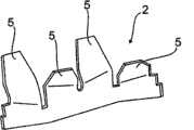
在图1中示意性示出根据本发明的静态混合器1的俯视图,如特别是结合图3和图4可看出的,所述静态混合器1由第一保持板条组的三个设计成相同配件的保持板条2和第二保持板条组的两个设计成相同配件的保持板条3构成,所述保持板条以下文将详细描述的方式方法固定在静态混合器的混合器环4中。FIG. 1 schematically shows a top view of a static mixer 1 according to the invention, as can be seen in particular in conjunction with FIGS. 3 and 4 , which consists of three designs of the first holding slat set The
如图4所示,保持板条2分别具有一基本为S形的弯曲部,其中在保持板条纵向方向上观察,设置有多个彼此间隔开的单叶的板状导流叶片5。导流叶片5分别从保持板条2的同一侧、进而在安装状态下——如图1所示——从混合器平面的相同侧伸出,其中沿保持板条纵向方向观察,各导流叶片交替地指向相反方向并以预先给定的角度倾斜于混合器平面。As shown in FIG. 4 , the
第二保持板条组的保持板条3(在图3中示出)同样设计成弯曲的并且大致在沿保持板条纵向方向的中心区域中具有一帽形突起部6。此外,在保持板条3的在图3的附图平面中位于左侧的端部区域上设置有一板状的导流叶片7,所述导流叶片7同样以一给定的角度倾斜。The
如现在特别是由图1结合图2可以看出的,第一保持板条组的保持板条2在安装状态下如此以彼此间隔开并基本上平行延伸的方式取向,使得各导流叶片5在由混合器环4形成的混合器平面中形成导流叶片排8、9、10和11,其中每个导流叶片排8、9、10、11的保持板条2的导流叶片5分别接续地设置并朝向相同方向倾斜或取向。As can now be seen in particular from FIG. 1 in conjunction with FIG. 2 , the
如可从图1和图2中进一步获悉的,由此形成导流叶片排8、9、10、11,通过保持板条2连同设置在保持板条2上的且指向相反方向的导流叶片5的特殊设计,所述导流叶片排8、9、10、11同样交替地指向相反方向,也就是说使得各直接相邻的导流叶片排分别具有指向相反方向的导流叶片5。As can further be seen from FIGS. 1 and 2 , guide
与此相反,第二保持板条组的保持板条3(在图1和图2中以黑粗线和加阴影的导流叶片示出)以基本上横向于第一保持板条组的保持板条2延伸的方式安装在混合器环4中,其中两个保持板条3如此以相互错开并旋转180°的方式设置在由混合器环4形成的混合器平面中,使得所述突起部6以预先给定的隙间距12结束于混合器环4之前。如可从图1和图2进一步获悉的,通过保持板条3的这种布置,所述保持板条3的导流叶片7到达导流叶片空位13、14,所述导流叶片空位13、14取决于结构地通过保持板条2连同其导流叶片5的结构而形成,从而使保持板条3的导流叶片7“无缝地”排列入导流叶片排9、10中并补足导流叶片排。In contrast, the holding
如可从图1和图2进一步获悉的,中间的保持板条2利用自由端部例如通过焊接固定在突起部6的区域中,而其余的保持板条2的自由端部如同保持板条3的自由端部那样通过例如点焊连接(部)与混合器环4的内侧相连接。As can further be seen from FIGS. 1 and 2 , the
此外如可从图3和图4进一步获悉的,在保持板条3上设置有狭缝状凹部15、16和17,所述狭缝状凹部相应地接纳和包围保持板条2的对应的保持板条区域,由此使所述狭缝状凹部和对应的保持板条区域以插塞连接的方式彼此连接并例如能以简单的方式预固定或者预安装。此外由此确保了:保持板条2、3的导流叶片5、7在混合器1的安装状态下基本上处于相同的水平面中。Furthermore, as can further be seen from FIGS. 3 and 4 , slit-shaped
Claims (26)
Applications Claiming Priority (3)
| Application Number | Priority Date | Filing Date | Title |
|---|---|---|---|
| DE102007048558.3 | 2007-10-09 | ||
| DE102007048558ADE102007048558A1 (en) | 2007-10-09 | 2007-10-09 | Static mixer for an exhaust system of an internal combustion engine-driven vehicle, in particular of a motor vehicle |
| PCT/EP2008/008436WO2009049790A1 (en) | 2007-10-09 | 2008-10-07 | Static mixer for an exhaust gas system of an internal combustion engine-driven vehicle, in particular motor vehicle |
Publications (2)
| Publication Number | Publication Date |
|---|---|
| CN101883625A CN101883625A (en) | 2010-11-10 |
| CN101883625Btrue CN101883625B (en) | 2013-06-19 |
Family
ID=40225222
Family Applications (1)
| Application Number | Title | Priority Date | Filing Date |
|---|---|---|---|
| CN2008801186000AExpired - Fee RelatedCN101883625B (en) | 2007-10-09 | 2008-10-07 | Static mixer for the exhaust system of an engine-driven vehicle, in particular a motor vehicle |
Country Status (5)
| Country | Link |
|---|---|
| US (1) | US9003771B2 (en) |
| EP (1) | EP2205345B1 (en) |
| CN (1) | CN101883625B (en) |
| DE (1) | DE102007048558A1 (en) |
| WO (1) | WO2009049790A1 (en) |
Families Citing this family (32)
| Publication number | Priority date | Publication date | Assignee | Title |
|---|---|---|---|---|
| DE102008017395C5 (en) | 2008-04-05 | 2018-01-25 | Eberspächer Exhaust Technology GmbH & Co. KG | Mixing and / or evaporation device |
| US9095827B2 (en) | 2008-04-21 | 2015-08-04 | Tenneco Automotive Operating Company Inc. | Exhaust gas flow mixer |
| US8939638B2 (en) | 2008-04-21 | 2015-01-27 | Tenneco Automotive Operating Company Inc. | Method for mixing an exhaust gas flow |
| DE102008020827A1 (en)* | 2008-04-25 | 2009-11-05 | Presswerk Struthütten GmbH | Mixer, method of making such and mixer assembly |
| US8935918B2 (en)* | 2010-04-23 | 2015-01-20 | GM Global Technology Operations LLC | Reconfigurable mixer for an exhaust aftertreatment system and method of using the same |
| DE102011077645A1 (en)* | 2011-06-16 | 2012-12-20 | Bosch Emission Systems Gmbh & Co. Kg | Static mixer |
| DE102011083636B4 (en)* | 2011-09-28 | 2016-11-10 | Eberspächer Exhaust Technology GmbH & Co. KG | Mixing and / or evaporation device |
| GB201207201D0 (en)* | 2012-04-24 | 2012-06-06 | Perkins Engines Co Ltd | Emissions cleaning module for a diesel engine |
| USD697942S1 (en) | 2012-05-23 | 2014-01-21 | Katcon Global, S.A. | Mixer assembly |
| US20150151259A1 (en)* | 2012-05-24 | 2015-06-04 | Sulzer Mixpac Ag | Mixer for mixing at least two flowable components |
| KR101696203B1 (en)* | 2012-08-10 | 2017-01-13 | 테네코 오토모티브 오퍼레이팅 컴파니 인코포레이티드 | Method for mixing an exhaust gas flow |
| DE102012016423B3 (en)* | 2012-08-21 | 2014-02-27 | Eberspächer Exhaust Technology GmbH & Co. KG | Exhaust system with mixing and or evaporation device |
| WO2014032052A1 (en) | 2012-08-24 | 2014-02-27 | Cummins Ip, Inc. | Reductant injection and mixing system |
| JP6105230B2 (en)* | 2012-08-24 | 2017-03-29 | フタバ産業株式会社 | Exhaust stirrer |
| DE102012216923B4 (en)* | 2012-09-20 | 2016-01-28 | Eberspächer Exhaust Technology GmbH & Co. KG | Exhaust system for a motor vehicle |
| US20150040547A1 (en)* | 2013-08-08 | 2015-02-12 | Tenneco Automotive Operating Company Inc. | Mirrored Two-Stage Mixer |
| US11040319B2 (en)* | 2014-01-07 | 2021-06-22 | Harry Glass | Vortex mixing baffle |
| PT2910301T (en) | 2014-02-21 | 2016-12-02 | Modulo S R L | Machine and method to produce urea mixers for exhaust devices of vehicles with internal-combustion engines |
| DE102014222296A1 (en)* | 2014-10-31 | 2016-05-04 | Eberspächer Exhaust Technology GmbH & Co. KG | Exhaust gas treatment device |
| DE102014018852B4 (en) | 2014-12-17 | 2023-02-02 | Audi Ag | Exhaust system of an internal combustion engine with a mixer provided with a non-stick coating for a liquid reducing agent |
| US9534525B2 (en) | 2015-05-27 | 2017-01-03 | Tenneco Automotive Operating Company Inc. | Mixer assembly for exhaust aftertreatment system |
| EP3167954B1 (en)* | 2015-11-12 | 2019-03-27 | Doosan Heavy Industries & Construction Co., Ltd. | Static mixer |
| MX2018005990A (en) | 2015-11-13 | 2018-11-29 | Re Mixers Inc | Static mixer. |
| GB2566907B (en)* | 2016-07-07 | 2021-09-22 | Caterpillar Inc | Dual mixer for exhaust gas aftertreatment systems |
| US10577996B2 (en)* | 2017-12-20 | 2020-03-03 | Caterpillar Inc. | Exhaust conduit with a flow conditioning portion |
| WO2021081122A1 (en) | 2019-10-21 | 2021-04-29 | Re Mixers, Inc | Static mixer |
| US10941692B1 (en)* | 2019-11-01 | 2021-03-09 | Tenneco Automotive Operating Company Inc. | Mixer assembly for exhaust aftertreatment system |
| USD959514S1 (en)* | 2020-07-17 | 2022-08-02 | Commonwealth Scientific And Industrial Research Organisation | Static mixer |
| USD959517S1 (en)* | 2020-07-23 | 2022-08-02 | Commonwealth Scientific And Industrial Research Organisation | Static mixer |
| USD959518S1 (en)* | 2020-07-23 | 2022-08-02 | Commonwealth Scientific And Industrial Research Organisation | Static mixer |
| US11268423B1 (en)* | 2020-09-10 | 2022-03-08 | Tenneco Automotive Operating Company Inc. | Two-part two-stage mixer |
| JP2024079007A (en)* | 2022-11-30 | 2024-06-11 | トヨタ自動車株式会社 | exhaust manifold |
Citations (2)
| Publication number | Priority date | Publication date | Assignee | Title |
|---|---|---|---|---|
| EP1712751A2 (en)* | 2005-04-15 | 2006-10-18 | Iveco S.p.A. | Static mixer |
| CN101029590A (en)* | 2006-03-02 | 2007-09-05 | J.埃贝斯佩歇合资公司 | Static mixer and exhaust treatment device |
Family Cites Families (11)
| Publication number | Priority date | Publication date | Assignee | Title |
|---|---|---|---|---|
| US4255124A (en)* | 1978-10-05 | 1981-03-10 | Baranowski Jr Frank | Static fluid-swirl mixing |
| DE4123161A1 (en) | 1991-07-12 | 1993-01-14 | Siemens Ag | STATIC MIXER |
| US5526462A (en) | 1993-03-22 | 1996-06-11 | Ngk Insulators, Ltd. | Honeycomb heater with mounting means preventing axial-displacement and absorbing radial displacement |
| DE19922355A1 (en) | 1999-05-14 | 2000-11-23 | Helmut Swars | Catalyst carrier for treating IC engine exhaust gases has a number of continuous flow paths for a fluid medium and carrier elements for a catalyst material extending in the longitudinal direction of the paths |
| DE102005041841A1 (en)* | 2005-09-02 | 2007-03-08 | Emitec Gesellschaft Für Emissionstechnologie Mbh | Method and device for adding a reactant to an exhaust gas of an internal combustion engine |
| DE102006055036B4 (en)* | 2006-11-22 | 2023-03-02 | Faurecia Emissions Control Technologies, Germany Gmbh | Mixing element and exhaust system for an internal combustion engine |
| DE102006058715B3 (en)* | 2006-12-13 | 2008-01-10 | Audi Ag | Static mixer for an exhaust gas unit on a vehicle operated by an internal combustion engine has flow-control elements influencing exhaust gas flow and slanted at a preset angle against a mixer surface |
| DE102007009890B4 (en) | 2007-02-28 | 2025-05-28 | Emcon Technologies Germany (Augsburg) Gmbh | Static mixing element and method for producing a static mixing element |
| US7908845B2 (en)* | 2007-04-16 | 2011-03-22 | GM Global Technology Operations LLC | Mixing apparatus for an exhaust after-treatment system |
| DE102007020812B4 (en) | 2007-05-04 | 2010-01-14 | Audi Ag | Apparatus and method for the addition of fluid pollutant-reducing media in an exhaust passage of an internal combustion engine |
| US8935918B2 (en)* | 2010-04-23 | 2015-01-20 | GM Global Technology Operations LLC | Reconfigurable mixer for an exhaust aftertreatment system and method of using the same |
- 2007
- 2007-10-09DEDE102007048558Apatent/DE102007048558A1/ennot_activeWithdrawn
- 2008
- 2008-10-07CNCN2008801186000Apatent/CN101883625B/ennot_activeExpired - Fee Related
- 2008-10-07WOPCT/EP2008/008436patent/WO2009049790A1/enactiveApplication Filing
- 2008-10-07EPEP08839941.5Apatent/EP2205345B1/ennot_activeNot-in-force
- 2008-10-07USUS12/682,219patent/US9003771B2/enactiveActive
Patent Citations (2)
| Publication number | Priority date | Publication date | Assignee | Title |
|---|---|---|---|---|
| EP1712751A2 (en)* | 2005-04-15 | 2006-10-18 | Iveco S.p.A. | Static mixer |
| CN101029590A (en)* | 2006-03-02 | 2007-09-05 | J.埃贝斯佩歇合资公司 | Static mixer and exhaust treatment device |
Also Published As
| Publication number | Publication date |
|---|---|
| CN101883625A (en) | 2010-11-10 |
| US9003771B2 (en) | 2015-04-14 |
| DE102007048558A1 (en) | 2009-04-16 |
| WO2009049790A1 (en) | 2009-04-23 |
| US20100293931A1 (en) | 2010-11-25 |
| EP2205345B1 (en) | 2013-05-15 |
| EP2205345A1 (en) | 2010-07-14 |
Similar Documents
| Publication | Publication Date | Title |
|---|---|---|
| CN101883625B (en) | Static mixer for the exhaust system of an engine-driven vehicle, in particular a motor vehicle | |
| US8066424B2 (en) | Mixing device | |
| KR100366679B1 (en) | Static mixer | |
| US8939638B2 (en) | Method for mixing an exhaust gas flow | |
| US10232328B2 (en) | Gas mixing arrangement | |
| US8607555B2 (en) | Mixing element and an exhaust system for an internal combustion engine | |
| CN104520549B (en) | Method for mixing exhaust streams | |
| KR102017485B1 (en) | Flue gas mixing apparatus | |
| US7562521B2 (en) | SCR muffler | |
| US9095827B2 (en) | Exhaust gas flow mixer | |
| CN105569785B (en) | Emission-control equipment | |
| US8984863B2 (en) | Ammonia injection device | |
| CN103670619B (en) | Gas extraction system for motor vehicles | |
| US6086241A (en) | Combined mixing and deflection unit | |
| CN102444453A (en) | Static mixer of exhaust system | |
| US20100074814A1 (en) | Reductant decomposition mixer and method for making the same | |
| CN112717683B (en) | A triangular multi-channel SCR static mixer | |
| EP3524789B1 (en) | Selective catalytic reduction system | |
| CN106460621A (en) | Exhaust gas stirring device | |
| KR20200096098A (en) | Reductant supply device and method for operating reductant supply device | |
| WO2011020200A1 (en) | Static mixer and its use, f. ex. for catalytic denitrification of exhaust gases and the like | |
| US20150247438A1 (en) | Catalyst device, element box for a catalytic device, and handling tool for handling the element box | |
| US10577996B2 (en) | Exhaust conduit with a flow conditioning portion | |
| CN219848976U (en) | Nozzle assembly suitable for denitration and self-turbulent flow type ammonia spraying grid device | |
| CA2162718C (en) | Plate catalyst |
Legal Events
| Date | Code | Title | Description |
|---|---|---|---|
| C06 | Publication | ||
| PB01 | Publication | ||
| C10 | Entry into substantive examination | ||
| SE01 | Entry into force of request for substantive examination | ||
| C14 | Grant of patent or utility model | ||
| GR01 | Patent grant | ||
| CF01 | Termination of patent right due to non-payment of annual fee | Granted publication date:20130619 |