CN101878007A - Intersomatic fusion device, intervertebral disc prosthesis, anchoring device and implantation instrument - Google Patents
Intersomatic fusion device, intervertebral disc prosthesis, anchoring device and implantation instrumentDownload PDFInfo
- Publication number
- CN101878007A CN101878007ACN2008800254227ACN200880025422ACN101878007ACN 101878007 ACN101878007 ACN 101878007ACN 2008800254227 ACN2008800254227 ACN 2008800254227ACN 200880025422 ACN200880025422 ACN 200880025422ACN 101878007 ACN101878007 ACN 101878007A
- Authority
- CN
- China
- Prior art keywords
- anchoring device
- fusion
- vertebra
- fusion device
- cage
- Prior art date
- Legal status (The legal status is an assumption and is not a legal conclusion. Google has not performed a legal analysis and makes no representation as to the accuracy of the status listed.)
- Granted
Links
Images


Classifications
- A—HUMAN NECESSITIES
- A61—MEDICAL OR VETERINARY SCIENCE; HYGIENE
- A61B—DIAGNOSIS; SURGERY; IDENTIFICATION
- A61B17/00—Surgical instruments, devices or methods
- A61B17/56—Surgical instruments or methods for treatment of bones or joints; Devices specially adapted therefor
- A61B17/58—Surgical instruments or methods for treatment of bones or joints; Devices specially adapted therefor for osteosynthesis, e.g. bone plates, screws or setting implements
- A61B17/88—Osteosynthesis instruments; Methods or means for implanting or extracting internal or external fixation devices
- A—HUMAN NECESSITIES
- A61—MEDICAL OR VETERINARY SCIENCE; HYGIENE
- A61B—DIAGNOSIS; SURGERY; IDENTIFICATION
- A61B17/00—Surgical instruments, devices or methods
- A61B17/064—Surgical staples, i.e. penetrating the tissue
- A61B17/0642—Surgical staples, i.e. penetrating the tissue for bones, e.g. for osteosynthesis or connecting tendon to bone
- A—HUMAN NECESSITIES
- A61—MEDICAL OR VETERINARY SCIENCE; HYGIENE
- A61B—DIAGNOSIS; SURGERY; IDENTIFICATION
- A61B17/00—Surgical instruments, devices or methods
- A61B17/56—Surgical instruments or methods for treatment of bones or joints; Devices specially adapted therefor
- A61B17/58—Surgical instruments or methods for treatment of bones or joints; Devices specially adapted therefor for osteosynthesis, e.g. bone plates, screws or setting implements
- A61B17/68—Internal fixation devices, including fasteners and spinal fixators, even if a part thereof projects from the skin
- A61B17/70—Spinal positioners or stabilisers, e.g. stabilisers comprising fluid filler in an implant
- A—HUMAN NECESSITIES
- A61—MEDICAL OR VETERINARY SCIENCE; HYGIENE
- A61B—DIAGNOSIS; SURGERY; IDENTIFICATION
- A61B17/00—Surgical instruments, devices or methods
- A61B17/56—Surgical instruments or methods for treatment of bones or joints; Devices specially adapted therefor
- A61B17/58—Surgical instruments or methods for treatment of bones or joints; Devices specially adapted therefor for osteosynthesis, e.g. bone plates, screws or setting implements
- A61B17/68—Internal fixation devices, including fasteners and spinal fixators, even if a part thereof projects from the skin
- A61B17/80—Cortical plates, i.e. bone plates; Instruments for holding or positioning cortical plates, or for compressing bones attached to cortical plates
- A61B17/809—Cortical plates, i.e. bone plates; Instruments for holding or positioning cortical plates, or for compressing bones attached to cortical plates with bone-penetrating elements, e.g. blades or prongs
- A—HUMAN NECESSITIES
- A61—MEDICAL OR VETERINARY SCIENCE; HYGIENE
- A61F—FILTERS IMPLANTABLE INTO BLOOD VESSELS; PROSTHESES; DEVICES PROVIDING PATENCY TO, OR PREVENTING COLLAPSING OF, TUBULAR STRUCTURES OF THE BODY, e.g. STENTS; ORTHOPAEDIC, NURSING OR CONTRACEPTIVE DEVICES; FOMENTATION; TREATMENT OR PROTECTION OF EYES OR EARS; BANDAGES, DRESSINGS OR ABSORBENT PADS; FIRST-AID KITS
- A61F2/00—Filters implantable into blood vessels; Prostheses, i.e. artificial substitutes or replacements for parts of the body; Appliances for connecting them with the body; Devices providing patency to, or preventing collapsing of, tubular structures of the body, e.g. stents
- A61F2/02—Prostheses implantable into the body
- A61F2/30—Joints
- A61F2/30721—Accessories
- A61F2/30749—Fixation appliances for connecting prostheses to the body
- A—HUMAN NECESSITIES
- A61—MEDICAL OR VETERINARY SCIENCE; HYGIENE
- A61F—FILTERS IMPLANTABLE INTO BLOOD VESSELS; PROSTHESES; DEVICES PROVIDING PATENCY TO, OR PREVENTING COLLAPSING OF, TUBULAR STRUCTURES OF THE BODY, e.g. STENTS; ORTHOPAEDIC, NURSING OR CONTRACEPTIVE DEVICES; FOMENTATION; TREATMENT OR PROTECTION OF EYES OR EARS; BANDAGES, DRESSINGS OR ABSORBENT PADS; FIRST-AID KITS
- A61F2/00—Filters implantable into blood vessels; Prostheses, i.e. artificial substitutes or replacements for parts of the body; Appliances for connecting them with the body; Devices providing patency to, or preventing collapsing of, tubular structures of the body, e.g. stents
- A61F2/02—Prostheses implantable into the body
- A61F2/30—Joints
- A61F2/44—Joints for the spine, e.g. vertebrae, spinal discs
- A61F2/442—Intervertebral or spinal discs, e.g. resilient
- A61F2/4425—Intervertebral or spinal discs, e.g. resilient made of articulated components
- A—HUMAN NECESSITIES
- A61—MEDICAL OR VETERINARY SCIENCE; HYGIENE
- A61F—FILTERS IMPLANTABLE INTO BLOOD VESSELS; PROSTHESES; DEVICES PROVIDING PATENCY TO, OR PREVENTING COLLAPSING OF, TUBULAR STRUCTURES OF THE BODY, e.g. STENTS; ORTHOPAEDIC, NURSING OR CONTRACEPTIVE DEVICES; FOMENTATION; TREATMENT OR PROTECTION OF EYES OR EARS; BANDAGES, DRESSINGS OR ABSORBENT PADS; FIRST-AID KITS
- A61F2/00—Filters implantable into blood vessels; Prostheses, i.e. artificial substitutes or replacements for parts of the body; Appliances for connecting them with the body; Devices providing patency to, or preventing collapsing of, tubular structures of the body, e.g. stents
- A61F2/02—Prostheses implantable into the body
- A61F2/30—Joints
- A61F2/44—Joints for the spine, e.g. vertebrae, spinal discs
- A61F2/4455—Joints for the spine, e.g. vertebrae, spinal discs for the fusion of spinal bodies, e.g. intervertebral fusion of adjacent spinal bodies, e.g. fusion cages
- A61F2/4465—Joints for the spine, e.g. vertebrae, spinal discs for the fusion of spinal bodies, e.g. intervertebral fusion of adjacent spinal bodies, e.g. fusion cages having a circular or kidney shaped cross-section substantially perpendicular to the axis of the spine
- A—HUMAN NECESSITIES
- A61—MEDICAL OR VETERINARY SCIENCE; HYGIENE
- A61F—FILTERS IMPLANTABLE INTO BLOOD VESSELS; PROSTHESES; DEVICES PROVIDING PATENCY TO, OR PREVENTING COLLAPSING OF, TUBULAR STRUCTURES OF THE BODY, e.g. STENTS; ORTHOPAEDIC, NURSING OR CONTRACEPTIVE DEVICES; FOMENTATION; TREATMENT OR PROTECTION OF EYES OR EARS; BANDAGES, DRESSINGS OR ABSORBENT PADS; FIRST-AID KITS
- A61F2/00—Filters implantable into blood vessels; Prostheses, i.e. artificial substitutes or replacements for parts of the body; Appliances for connecting them with the body; Devices providing patency to, or preventing collapsing of, tubular structures of the body, e.g. stents
- A61F2/02—Prostheses implantable into the body
- A61F2/30—Joints
- A61F2/44—Joints for the spine, e.g. vertebrae, spinal discs
- A61F2/4455—Joints for the spine, e.g. vertebrae, spinal discs for the fusion of spinal bodies, e.g. intervertebral fusion of adjacent spinal bodies, e.g. fusion cages
- A61F2/447—Joints for the spine, e.g. vertebrae, spinal discs for the fusion of spinal bodies, e.g. intervertebral fusion of adjacent spinal bodies, e.g. fusion cages substantially parallelepipedal, e.g. having a rectangular or trapezoidal cross-section
- A—HUMAN NECESSITIES
- A61—MEDICAL OR VETERINARY SCIENCE; HYGIENE
- A61F—FILTERS IMPLANTABLE INTO BLOOD VESSELS; PROSTHESES; DEVICES PROVIDING PATENCY TO, OR PREVENTING COLLAPSING OF, TUBULAR STRUCTURES OF THE BODY, e.g. STENTS; ORTHOPAEDIC, NURSING OR CONTRACEPTIVE DEVICES; FOMENTATION; TREATMENT OR PROTECTION OF EYES OR EARS; BANDAGES, DRESSINGS OR ABSORBENT PADS; FIRST-AID KITS
- A61F2/00—Filters implantable into blood vessels; Prostheses, i.e. artificial substitutes or replacements for parts of the body; Appliances for connecting them with the body; Devices providing patency to, or preventing collapsing of, tubular structures of the body, e.g. stents
- A61F2/02—Prostheses implantable into the body
- A61F2/30—Joints
- A61F2/46—Special tools for implanting artificial joints
- A61F2/4603—Special tools for implanting artificial joints for insertion or extraction of endoprosthetic joints or of accessories thereof
- A61F2/4611—Special tools for implanting artificial joints for insertion or extraction of endoprosthetic joints or of accessories thereof of spinal prostheses
- A—HUMAN NECESSITIES
- A61—MEDICAL OR VETERINARY SCIENCE; HYGIENE
- A61F—FILTERS IMPLANTABLE INTO BLOOD VESSELS; PROSTHESES; DEVICES PROVIDING PATENCY TO, OR PREVENTING COLLAPSING OF, TUBULAR STRUCTURES OF THE BODY, e.g. STENTS; ORTHOPAEDIC, NURSING OR CONTRACEPTIVE DEVICES; FOMENTATION; TREATMENT OR PROTECTION OF EYES OR EARS; BANDAGES, DRESSINGS OR ABSORBENT PADS; FIRST-AID KITS
- A61F2/00—Filters implantable into blood vessels; Prostheses, i.e. artificial substitutes or replacements for parts of the body; Appliances for connecting them with the body; Devices providing patency to, or preventing collapsing of, tubular structures of the body, e.g. stents
- A61F2/02—Prostheses implantable into the body
- A61F2/28—Bones
- A61F2002/2835—Bone graft implants for filling a bony defect or an endoprosthesis cavity, e.g. by synthetic material or biological material
- A—HUMAN NECESSITIES
- A61—MEDICAL OR VETERINARY SCIENCE; HYGIENE
- A61F—FILTERS IMPLANTABLE INTO BLOOD VESSELS; PROSTHESES; DEVICES PROVIDING PATENCY TO, OR PREVENTING COLLAPSING OF, TUBULAR STRUCTURES OF THE BODY, e.g. STENTS; ORTHOPAEDIC, NURSING OR CONTRACEPTIVE DEVICES; FOMENTATION; TREATMENT OR PROTECTION OF EYES OR EARS; BANDAGES, DRESSINGS OR ABSORBENT PADS; FIRST-AID KITS
- A61F2/00—Filters implantable into blood vessels; Prostheses, i.e. artificial substitutes or replacements for parts of the body; Appliances for connecting them with the body; Devices providing patency to, or preventing collapsing of, tubular structures of the body, e.g. stents
- A61F2/02—Prostheses implantable into the body
- A61F2/30—Joints
- A61F2002/30001—Additional features of subject-matter classified in A61F2/28, A61F2/30 and subgroups thereof
- A61F2002/30108—Shapes
- A61F2002/3011—Cross-sections or two-dimensional shapes
- A61F2002/30112—Rounded shapes, e.g. with rounded corners
- A61F2002/30113—Rounded shapes, e.g. with rounded corners circular
- A61F2002/30116—Rounded shapes, e.g. with rounded corners circular partial circles, i.e. circular segments
- A—HUMAN NECESSITIES
- A61—MEDICAL OR VETERINARY SCIENCE; HYGIENE
- A61F—FILTERS IMPLANTABLE INTO BLOOD VESSELS; PROSTHESES; DEVICES PROVIDING PATENCY TO, OR PREVENTING COLLAPSING OF, TUBULAR STRUCTURES OF THE BODY, e.g. STENTS; ORTHOPAEDIC, NURSING OR CONTRACEPTIVE DEVICES; FOMENTATION; TREATMENT OR PROTECTION OF EYES OR EARS; BANDAGES, DRESSINGS OR ABSORBENT PADS; FIRST-AID KITS
- A61F2/00—Filters implantable into blood vessels; Prostheses, i.e. artificial substitutes or replacements for parts of the body; Appliances for connecting them with the body; Devices providing patency to, or preventing collapsing of, tubular structures of the body, e.g. stents
- A61F2/02—Prostheses implantable into the body
- A61F2/30—Joints
- A61F2002/30001—Additional features of subject-matter classified in A61F2/28, A61F2/30 and subgroups thereof
- A61F2002/30108—Shapes
- A61F2002/30199—Three-dimensional shapes
- A61F2002/302—Three-dimensional shapes toroidal, e.g. rings
- A—HUMAN NECESSITIES
- A61—MEDICAL OR VETERINARY SCIENCE; HYGIENE
- A61F—FILTERS IMPLANTABLE INTO BLOOD VESSELS; PROSTHESES; DEVICES PROVIDING PATENCY TO, OR PREVENTING COLLAPSING OF, TUBULAR STRUCTURES OF THE BODY, e.g. STENTS; ORTHOPAEDIC, NURSING OR CONTRACEPTIVE DEVICES; FOMENTATION; TREATMENT OR PROTECTION OF EYES OR EARS; BANDAGES, DRESSINGS OR ABSORBENT PADS; FIRST-AID KITS
- A61F2/00—Filters implantable into blood vessels; Prostheses, i.e. artificial substitutes or replacements for parts of the body; Appliances for connecting them with the body; Devices providing patency to, or preventing collapsing of, tubular structures of the body, e.g. stents
- A61F2/02—Prostheses implantable into the body
- A61F2/30—Joints
- A61F2002/30001—Additional features of subject-matter classified in A61F2/28, A61F2/30 and subgroups thereof
- A61F2002/30316—The prosthesis having different structural features at different locations within the same prosthesis; Connections between prosthetic parts; Special structural features of bone or joint prostheses not otherwise provided for
- A61F2002/30329—Connections or couplings between prosthetic parts, e.g. between modular parts; Connecting elements
- A61F2002/30331—Connections or couplings between prosthetic parts, e.g. between modular parts; Connecting elements made by longitudinally pushing a protrusion into a complementarily-shaped recess, e.g. held by friction fit
- A—HUMAN NECESSITIES
- A61—MEDICAL OR VETERINARY SCIENCE; HYGIENE
- A61F—FILTERS IMPLANTABLE INTO BLOOD VESSELS; PROSTHESES; DEVICES PROVIDING PATENCY TO, OR PREVENTING COLLAPSING OF, TUBULAR STRUCTURES OF THE BODY, e.g. STENTS; ORTHOPAEDIC, NURSING OR CONTRACEPTIVE DEVICES; FOMENTATION; TREATMENT OR PROTECTION OF EYES OR EARS; BANDAGES, DRESSINGS OR ABSORBENT PADS; FIRST-AID KITS
- A61F2/00—Filters implantable into blood vessels; Prostheses, i.e. artificial substitutes or replacements for parts of the body; Appliances for connecting them with the body; Devices providing patency to, or preventing collapsing of, tubular structures of the body, e.g. stents
- A61F2/02—Prostheses implantable into the body
- A61F2/30—Joints
- A61F2002/30001—Additional features of subject-matter classified in A61F2/28, A61F2/30 and subgroups thereof
- A61F2002/30316—The prosthesis having different structural features at different locations within the same prosthesis; Connections between prosthetic parts; Special structural features of bone or joint prostheses not otherwise provided for
- A61F2002/30329—Connections or couplings between prosthetic parts, e.g. between modular parts; Connecting elements
- A61F2002/30476—Connections or couplings between prosthetic parts, e.g. between modular parts; Connecting elements locked by an additional locking mechanism
- A61F2002/305—Snap connection
- A—HUMAN NECESSITIES
- A61—MEDICAL OR VETERINARY SCIENCE; HYGIENE
- A61F—FILTERS IMPLANTABLE INTO BLOOD VESSELS; PROSTHESES; DEVICES PROVIDING PATENCY TO, OR PREVENTING COLLAPSING OF, TUBULAR STRUCTURES OF THE BODY, e.g. STENTS; ORTHOPAEDIC, NURSING OR CONTRACEPTIVE DEVICES; FOMENTATION; TREATMENT OR PROTECTION OF EYES OR EARS; BANDAGES, DRESSINGS OR ABSORBENT PADS; FIRST-AID KITS
- A61F2/00—Filters implantable into blood vessels; Prostheses, i.e. artificial substitutes or replacements for parts of the body; Appliances for connecting them with the body; Devices providing patency to, or preventing collapsing of, tubular structures of the body, e.g. stents
- A61F2/02—Prostheses implantable into the body
- A61F2/30—Joints
- A61F2002/30001—Additional features of subject-matter classified in A61F2/28, A61F2/30 and subgroups thereof
- A61F2002/30316—The prosthesis having different structural features at different locations within the same prosthesis; Connections between prosthetic parts; Special structural features of bone or joint prostheses not otherwise provided for
- A61F2002/30329—Connections or couplings between prosthetic parts, e.g. between modular parts; Connecting elements
- A61F2002/30476—Connections or couplings between prosthetic parts, e.g. between modular parts; Connecting elements locked by an additional locking mechanism
- A61F2002/30517—Connections or couplings between prosthetic parts, e.g. between modular parts; Connecting elements locked by an additional locking mechanism using a locking plate
- A—HUMAN NECESSITIES
- A61—MEDICAL OR VETERINARY SCIENCE; HYGIENE
- A61F—FILTERS IMPLANTABLE INTO BLOOD VESSELS; PROSTHESES; DEVICES PROVIDING PATENCY TO, OR PREVENTING COLLAPSING OF, TUBULAR STRUCTURES OF THE BODY, e.g. STENTS; ORTHOPAEDIC, NURSING OR CONTRACEPTIVE DEVICES; FOMENTATION; TREATMENT OR PROTECTION OF EYES OR EARS; BANDAGES, DRESSINGS OR ABSORBENT PADS; FIRST-AID KITS
- A61F2/00—Filters implantable into blood vessels; Prostheses, i.e. artificial substitutes or replacements for parts of the body; Appliances for connecting them with the body; Devices providing patency to, or preventing collapsing of, tubular structures of the body, e.g. stents
- A61F2/02—Prostheses implantable into the body
- A61F2/30—Joints
- A61F2002/30001—Additional features of subject-matter classified in A61F2/28, A61F2/30 and subgroups thereof
- A61F2002/30316—The prosthesis having different structural features at different locations within the same prosthesis; Connections between prosthetic parts; Special structural features of bone or joint prostheses not otherwise provided for
- A61F2002/30535—Special structural features of bone or joint prostheses not otherwise provided for
- A61F2002/30576—Special structural features of bone or joint prostheses not otherwise provided for with extending fixation tabs
- A—HUMAN NECESSITIES
- A61—MEDICAL OR VETERINARY SCIENCE; HYGIENE
- A61F—FILTERS IMPLANTABLE INTO BLOOD VESSELS; PROSTHESES; DEVICES PROVIDING PATENCY TO, OR PREVENTING COLLAPSING OF, TUBULAR STRUCTURES OF THE BODY, e.g. STENTS; ORTHOPAEDIC, NURSING OR CONTRACEPTIVE DEVICES; FOMENTATION; TREATMENT OR PROTECTION OF EYES OR EARS; BANDAGES, DRESSINGS OR ABSORBENT PADS; FIRST-AID KITS
- A61F2/00—Filters implantable into blood vessels; Prostheses, i.e. artificial substitutes or replacements for parts of the body; Appliances for connecting them with the body; Devices providing patency to, or preventing collapsing of, tubular structures of the body, e.g. stents
- A61F2/02—Prostheses implantable into the body
- A61F2/30—Joints
- A61F2002/30001—Additional features of subject-matter classified in A61F2/28, A61F2/30 and subgroups thereof
- A61F2002/30316—The prosthesis having different structural features at different locations within the same prosthesis; Connections between prosthetic parts; Special structural features of bone or joint prostheses not otherwise provided for
- A61F2002/30535—Special structural features of bone or joint prostheses not otherwise provided for
- A61F2002/30579—Special structural features of bone or joint prostheses not otherwise provided for with mechanically expandable devices, e.g. fixation devices
- A—HUMAN NECESSITIES
- A61—MEDICAL OR VETERINARY SCIENCE; HYGIENE
- A61F—FILTERS IMPLANTABLE INTO BLOOD VESSELS; PROSTHESES; DEVICES PROVIDING PATENCY TO, OR PREVENTING COLLAPSING OF, TUBULAR STRUCTURES OF THE BODY, e.g. STENTS; ORTHOPAEDIC, NURSING OR CONTRACEPTIVE DEVICES; FOMENTATION; TREATMENT OR PROTECTION OF EYES OR EARS; BANDAGES, DRESSINGS OR ABSORBENT PADS; FIRST-AID KITS
- A61F2/00—Filters implantable into blood vessels; Prostheses, i.e. artificial substitutes or replacements for parts of the body; Appliances for connecting them with the body; Devices providing patency to, or preventing collapsing of, tubular structures of the body, e.g. stents
- A61F2/02—Prostheses implantable into the body
- A61F2/30—Joints
- A61F2002/30001—Additional features of subject-matter classified in A61F2/28, A61F2/30 and subgroups thereof
- A61F2002/30316—The prosthesis having different structural features at different locations within the same prosthesis; Connections between prosthetic parts; Special structural features of bone or joint prostheses not otherwise provided for
- A61F2002/30535—Special structural features of bone or joint prostheses not otherwise provided for
- A61F2002/30593—Special structural features of bone or joint prostheses not otherwise provided for hollow
- A—HUMAN NECESSITIES
- A61—MEDICAL OR VETERINARY SCIENCE; HYGIENE
- A61F—FILTERS IMPLANTABLE INTO BLOOD VESSELS; PROSTHESES; DEVICES PROVIDING PATENCY TO, OR PREVENTING COLLAPSING OF, TUBULAR STRUCTURES OF THE BODY, e.g. STENTS; ORTHOPAEDIC, NURSING OR CONTRACEPTIVE DEVICES; FOMENTATION; TREATMENT OR PROTECTION OF EYES OR EARS; BANDAGES, DRESSINGS OR ABSORBENT PADS; FIRST-AID KITS
- A61F2/00—Filters implantable into blood vessels; Prostheses, i.e. artificial substitutes or replacements for parts of the body; Appliances for connecting them with the body; Devices providing patency to, or preventing collapsing of, tubular structures of the body, e.g. stents
- A61F2/02—Prostheses implantable into the body
- A61F2/30—Joints
- A61F2002/30001—Additional features of subject-matter classified in A61F2/28, A61F2/30 and subgroups thereof
- A61F2002/30316—The prosthesis having different structural features at different locations within the same prosthesis; Connections between prosthetic parts; Special structural features of bone or joint prostheses not otherwise provided for
- A61F2002/30535—Special structural features of bone or joint prostheses not otherwise provided for
- A61F2002/30601—Special structural features of bone or joint prostheses not otherwise provided for telescopic
- A—HUMAN NECESSITIES
- A61—MEDICAL OR VETERINARY SCIENCE; HYGIENE
- A61F—FILTERS IMPLANTABLE INTO BLOOD VESSELS; PROSTHESES; DEVICES PROVIDING PATENCY TO, OR PREVENTING COLLAPSING OF, TUBULAR STRUCTURES OF THE BODY, e.g. STENTS; ORTHOPAEDIC, NURSING OR CONTRACEPTIVE DEVICES; FOMENTATION; TREATMENT OR PROTECTION OF EYES OR EARS; BANDAGES, DRESSINGS OR ABSORBENT PADS; FIRST-AID KITS
- A61F2/00—Filters implantable into blood vessels; Prostheses, i.e. artificial substitutes or replacements for parts of the body; Appliances for connecting them with the body; Devices providing patency to, or preventing collapsing of, tubular structures of the body, e.g. stents
- A61F2/02—Prostheses implantable into the body
- A61F2/30—Joints
- A61F2002/30001—Additional features of subject-matter classified in A61F2/28, A61F2/30 and subgroups thereof
- A61F2002/30621—Features concerning the anatomical functioning or articulation of the prosthetic joint
- A61F2002/30622—Implant for fusing a joint or bone material
- A—HUMAN NECESSITIES
- A61—MEDICAL OR VETERINARY SCIENCE; HYGIENE
- A61F—FILTERS IMPLANTABLE INTO BLOOD VESSELS; PROSTHESES; DEVICES PROVIDING PATENCY TO, OR PREVENTING COLLAPSING OF, TUBULAR STRUCTURES OF THE BODY, e.g. STENTS; ORTHOPAEDIC, NURSING OR CONTRACEPTIVE DEVICES; FOMENTATION; TREATMENT OR PROTECTION OF EYES OR EARS; BANDAGES, DRESSINGS OR ABSORBENT PADS; FIRST-AID KITS
- A61F2/00—Filters implantable into blood vessels; Prostheses, i.e. artificial substitutes or replacements for parts of the body; Appliances for connecting them with the body; Devices providing patency to, or preventing collapsing of, tubular structures of the body, e.g. stents
- A61F2/02—Prostheses implantable into the body
- A61F2/30—Joints
- A61F2002/30001—Additional features of subject-matter classified in A61F2/28, A61F2/30 and subgroups thereof
- A61F2002/30621—Features concerning the anatomical functioning or articulation of the prosthetic joint
- A61F2002/30649—Ball-and-socket joints
- A61F2002/30662—Ball-and-socket joints with rotation-limiting means
- A—HUMAN NECESSITIES
- A61—MEDICAL OR VETERINARY SCIENCE; HYGIENE
- A61F—FILTERS IMPLANTABLE INTO BLOOD VESSELS; PROSTHESES; DEVICES PROVIDING PATENCY TO, OR PREVENTING COLLAPSING OF, TUBULAR STRUCTURES OF THE BODY, e.g. STENTS; ORTHOPAEDIC, NURSING OR CONTRACEPTIVE DEVICES; FOMENTATION; TREATMENT OR PROTECTION OF EYES OR EARS; BANDAGES, DRESSINGS OR ABSORBENT PADS; FIRST-AID KITS
- A61F2/00—Filters implantable into blood vessels; Prostheses, i.e. artificial substitutes or replacements for parts of the body; Appliances for connecting them with the body; Devices providing patency to, or preventing collapsing of, tubular structures of the body, e.g. stents
- A61F2/02—Prostheses implantable into the body
- A61F2/30—Joints
- A61F2/30767—Special external or bone-contacting surface, e.g. coating for improving bone ingrowth
- A61F2/30771—Special external or bone-contacting surface, e.g. coating for improving bone ingrowth applied in original prostheses, e.g. holes or grooves
- A61F2002/30772—Apertures or holes, e.g. of circular cross section
- A61F2002/30777—Oblong apertures
- A—HUMAN NECESSITIES
- A61—MEDICAL OR VETERINARY SCIENCE; HYGIENE
- A61F—FILTERS IMPLANTABLE INTO BLOOD VESSELS; PROSTHESES; DEVICES PROVIDING PATENCY TO, OR PREVENTING COLLAPSING OF, TUBULAR STRUCTURES OF THE BODY, e.g. STENTS; ORTHOPAEDIC, NURSING OR CONTRACEPTIVE DEVICES; FOMENTATION; TREATMENT OR PROTECTION OF EYES OR EARS; BANDAGES, DRESSINGS OR ABSORBENT PADS; FIRST-AID KITS
- A61F2/00—Filters implantable into blood vessels; Prostheses, i.e. artificial substitutes or replacements for parts of the body; Appliances for connecting them with the body; Devices providing patency to, or preventing collapsing of, tubular structures of the body, e.g. stents
- A61F2/02—Prostheses implantable into the body
- A61F2/30—Joints
- A61F2/30767—Special external or bone-contacting surface, e.g. coating for improving bone ingrowth
- A61F2/30771—Special external or bone-contacting surface, e.g. coating for improving bone ingrowth applied in original prostheses, e.g. holes or grooves
- A61F2002/30772—Apertures or holes, e.g. of circular cross section
- A61F2002/30782—Apertures or holes, e.g. of circular cross section inclined obliquely
- A—HUMAN NECESSITIES
- A61—MEDICAL OR VETERINARY SCIENCE; HYGIENE
- A61F—FILTERS IMPLANTABLE INTO BLOOD VESSELS; PROSTHESES; DEVICES PROVIDING PATENCY TO, OR PREVENTING COLLAPSING OF, TUBULAR STRUCTURES OF THE BODY, e.g. STENTS; ORTHOPAEDIC, NURSING OR CONTRACEPTIVE DEVICES; FOMENTATION; TREATMENT OR PROTECTION OF EYES OR EARS; BANDAGES, DRESSINGS OR ABSORBENT PADS; FIRST-AID KITS
- A61F2/00—Filters implantable into blood vessels; Prostheses, i.e. artificial substitutes or replacements for parts of the body; Appliances for connecting them with the body; Devices providing patency to, or preventing collapsing of, tubular structures of the body, e.g. stents
- A61F2/02—Prostheses implantable into the body
- A61F2/30—Joints
- A61F2/30767—Special external or bone-contacting surface, e.g. coating for improving bone ingrowth
- A61F2/30771—Special external or bone-contacting surface, e.g. coating for improving bone ingrowth applied in original prostheses, e.g. holes or grooves
- A61F2002/30841—Sharp anchoring protrusions for impaction into the bone, e.g. sharp pins, spikes
- A61F2002/30845—Sharp anchoring protrusions for impaction into the bone, e.g. sharp pins, spikes with cutting edges
- A—HUMAN NECESSITIES
- A61—MEDICAL OR VETERINARY SCIENCE; HYGIENE
- A61F—FILTERS IMPLANTABLE INTO BLOOD VESSELS; PROSTHESES; DEVICES PROVIDING PATENCY TO, OR PREVENTING COLLAPSING OF, TUBULAR STRUCTURES OF THE BODY, e.g. STENTS; ORTHOPAEDIC, NURSING OR CONTRACEPTIVE DEVICES; FOMENTATION; TREATMENT OR PROTECTION OF EYES OR EARS; BANDAGES, DRESSINGS OR ABSORBENT PADS; FIRST-AID KITS
- A61F2/00—Filters implantable into blood vessels; Prostheses, i.e. artificial substitutes or replacements for parts of the body; Appliances for connecting them with the body; Devices providing patency to, or preventing collapsing of, tubular structures of the body, e.g. stents
- A61F2/02—Prostheses implantable into the body
- A61F2/30—Joints
- A61F2/30767—Special external or bone-contacting surface, e.g. coating for improving bone ingrowth
- A61F2/30771—Special external or bone-contacting surface, e.g. coating for improving bone ingrowth applied in original prostheses, e.g. holes or grooves
- A61F2002/30878—Special external or bone-contacting surface, e.g. coating for improving bone ingrowth applied in original prostheses, e.g. holes or grooves with non-sharp protrusions, for instance contacting the bone for anchoring, e.g. keels, pegs, pins, posts, shanks, stems, struts
- A61F2002/30879—Ribs
- A—HUMAN NECESSITIES
- A61—MEDICAL OR VETERINARY SCIENCE; HYGIENE
- A61F—FILTERS IMPLANTABLE INTO BLOOD VESSELS; PROSTHESES; DEVICES PROVIDING PATENCY TO, OR PREVENTING COLLAPSING OF, TUBULAR STRUCTURES OF THE BODY, e.g. STENTS; ORTHOPAEDIC, NURSING OR CONTRACEPTIVE DEVICES; FOMENTATION; TREATMENT OR PROTECTION OF EYES OR EARS; BANDAGES, DRESSINGS OR ABSORBENT PADS; FIRST-AID KITS
- A61F2/00—Filters implantable into blood vessels; Prostheses, i.e. artificial substitutes or replacements for parts of the body; Appliances for connecting them with the body; Devices providing patency to, or preventing collapsing of, tubular structures of the body, e.g. stents
- A61F2/02—Prostheses implantable into the body
- A61F2/30—Joints
- A61F2/30767—Special external or bone-contacting surface, e.g. coating for improving bone ingrowth
- A61F2/30771—Special external or bone-contacting surface, e.g. coating for improving bone ingrowth applied in original prostheses, e.g. holes or grooves
- A61F2002/30878—Special external or bone-contacting surface, e.g. coating for improving bone ingrowth applied in original prostheses, e.g. holes or grooves with non-sharp protrusions, for instance contacting the bone for anchoring, e.g. keels, pegs, pins, posts, shanks, stems, struts
- A61F2002/30884—Fins or wings, e.g. longitudinal wings for preventing rotation within the bone cavity
- A—HUMAN NECESSITIES
- A61—MEDICAL OR VETERINARY SCIENCE; HYGIENE
- A61F—FILTERS IMPLANTABLE INTO BLOOD VESSELS; PROSTHESES; DEVICES PROVIDING PATENCY TO, OR PREVENTING COLLAPSING OF, TUBULAR STRUCTURES OF THE BODY, e.g. STENTS; ORTHOPAEDIC, NURSING OR CONTRACEPTIVE DEVICES; FOMENTATION; TREATMENT OR PROTECTION OF EYES OR EARS; BANDAGES, DRESSINGS OR ABSORBENT PADS; FIRST-AID KITS
- A61F2/00—Filters implantable into blood vessels; Prostheses, i.e. artificial substitutes or replacements for parts of the body; Appliances for connecting them with the body; Devices providing patency to, or preventing collapsing of, tubular structures of the body, e.g. stents
- A61F2/02—Prostheses implantable into the body
- A61F2/30—Joints
- A61F2/30767—Special external or bone-contacting surface, e.g. coating for improving bone ingrowth
- A61F2/30771—Special external or bone-contacting surface, e.g. coating for improving bone ingrowth applied in original prostheses, e.g. holes or grooves
- A61F2002/30878—Special external or bone-contacting surface, e.g. coating for improving bone ingrowth applied in original prostheses, e.g. holes or grooves with non-sharp protrusions, for instance contacting the bone for anchoring, e.g. keels, pegs, pins, posts, shanks, stems, struts
- A61F2002/30889—Arcuate pegs
- A—HUMAN NECESSITIES
- A61—MEDICAL OR VETERINARY SCIENCE; HYGIENE
- A61F—FILTERS IMPLANTABLE INTO BLOOD VESSELS; PROSTHESES; DEVICES PROVIDING PATENCY TO, OR PREVENTING COLLAPSING OF, TUBULAR STRUCTURES OF THE BODY, e.g. STENTS; ORTHOPAEDIC, NURSING OR CONTRACEPTIVE DEVICES; FOMENTATION; TREATMENT OR PROTECTION OF EYES OR EARS; BANDAGES, DRESSINGS OR ABSORBENT PADS; FIRST-AID KITS
- A61F2/00—Filters implantable into blood vessels; Prostheses, i.e. artificial substitutes or replacements for parts of the body; Appliances for connecting them with the body; Devices providing patency to, or preventing collapsing of, tubular structures of the body, e.g. stents
- A61F2/02—Prostheses implantable into the body
- A61F2/30—Joints
- A61F2/30767—Special external or bone-contacting surface, e.g. coating for improving bone ingrowth
- A61F2/30771—Special external or bone-contacting surface, e.g. coating for improving bone ingrowth applied in original prostheses, e.g. holes or grooves
- A61F2002/30904—Special external or bone-contacting surface, e.g. coating for improving bone ingrowth applied in original prostheses, e.g. holes or grooves serrated profile, i.e. saw-toothed
- A—HUMAN NECESSITIES
- A61—MEDICAL OR VETERINARY SCIENCE; HYGIENE
- A61F—FILTERS IMPLANTABLE INTO BLOOD VESSELS; PROSTHESES; DEVICES PROVIDING PATENCY TO, OR PREVENTING COLLAPSING OF, TUBULAR STRUCTURES OF THE BODY, e.g. STENTS; ORTHOPAEDIC, NURSING OR CONTRACEPTIVE DEVICES; FOMENTATION; TREATMENT OR PROTECTION OF EYES OR EARS; BANDAGES, DRESSINGS OR ABSORBENT PADS; FIRST-AID KITS
- A61F2/00—Filters implantable into blood vessels; Prostheses, i.e. artificial substitutes or replacements for parts of the body; Appliances for connecting them with the body; Devices providing patency to, or preventing collapsing of, tubular structures of the body, e.g. stents
- A61F2/02—Prostheses implantable into the body
- A61F2/30—Joints
- A61F2/44—Joints for the spine, e.g. vertebrae, spinal discs
- A61F2/442—Intervertebral or spinal discs, e.g. resilient
- A61F2/4425—Intervertebral or spinal discs, e.g. resilient made of articulated components
- A61F2002/443—Intervertebral or spinal discs, e.g. resilient made of articulated components having two transversal endplates and at least one intermediate component
- A—HUMAN NECESSITIES
- A61—MEDICAL OR VETERINARY SCIENCE; HYGIENE
- A61F—FILTERS IMPLANTABLE INTO BLOOD VESSELS; PROSTHESES; DEVICES PROVIDING PATENCY TO, OR PREVENTING COLLAPSING OF, TUBULAR STRUCTURES OF THE BODY, e.g. STENTS; ORTHOPAEDIC, NURSING OR CONTRACEPTIVE DEVICES; FOMENTATION; TREATMENT OR PROTECTION OF EYES OR EARS; BANDAGES, DRESSINGS OR ABSORBENT PADS; FIRST-AID KITS
- A61F2/00—Filters implantable into blood vessels; Prostheses, i.e. artificial substitutes or replacements for parts of the body; Appliances for connecting them with the body; Devices providing patency to, or preventing collapsing of, tubular structures of the body, e.g. stents
- A61F2/02—Prostheses implantable into the body
- A61F2/30—Joints
- A61F2/44—Joints for the spine, e.g. vertebrae, spinal discs
- A61F2002/448—Joints for the spine, e.g. vertebrae, spinal discs comprising multiple adjacent spinal implants within the same intervertebral space or within the same vertebra, e.g. comprising two adjacent spinal implants
- A—HUMAN NECESSITIES
- A61—MEDICAL OR VETERINARY SCIENCE; HYGIENE
- A61F—FILTERS IMPLANTABLE INTO BLOOD VESSELS; PROSTHESES; DEVICES PROVIDING PATENCY TO, OR PREVENTING COLLAPSING OF, TUBULAR STRUCTURES OF THE BODY, e.g. STENTS; ORTHOPAEDIC, NURSING OR CONTRACEPTIVE DEVICES; FOMENTATION; TREATMENT OR PROTECTION OF EYES OR EARS; BANDAGES, DRESSINGS OR ABSORBENT PADS; FIRST-AID KITS
- A61F2/00—Filters implantable into blood vessels; Prostheses, i.e. artificial substitutes or replacements for parts of the body; Appliances for connecting them with the body; Devices providing patency to, or preventing collapsing of, tubular structures of the body, e.g. stents
- A61F2/02—Prostheses implantable into the body
- A61F2/30—Joints
- A61F2/46—Special tools for implanting artificial joints
- A61F2/4603—Special tools for implanting artificial joints for insertion or extraction of endoprosthetic joints or of accessories thereof
- A61F2002/4629—Special tools for implanting artificial joints for insertion or extraction of endoprosthetic joints or of accessories thereof connected to the endoprosthesis or implant via a threaded connection
- A—HUMAN NECESSITIES
- A61—MEDICAL OR VETERINARY SCIENCE; HYGIENE
- A61F—FILTERS IMPLANTABLE INTO BLOOD VESSELS; PROSTHESES; DEVICES PROVIDING PATENCY TO, OR PREVENTING COLLAPSING OF, TUBULAR STRUCTURES OF THE BODY, e.g. STENTS; ORTHOPAEDIC, NURSING OR CONTRACEPTIVE DEVICES; FOMENTATION; TREATMENT OR PROTECTION OF EYES OR EARS; BANDAGES, DRESSINGS OR ABSORBENT PADS; FIRST-AID KITS
- A61F2/00—Filters implantable into blood vessels; Prostheses, i.e. artificial substitutes or replacements for parts of the body; Appliances for connecting them with the body; Devices providing patency to, or preventing collapsing of, tubular structures of the body, e.g. stents
- A61F2/02—Prostheses implantable into the body
- A61F2/30—Joints
- A61F2/46—Special tools for implanting artificial joints
- A61F2002/4681—Special tools for implanting artificial joints by applying mechanical shocks, e.g. by hammering
- A—HUMAN NECESSITIES
- A61—MEDICAL OR VETERINARY SCIENCE; HYGIENE
- A61F—FILTERS IMPLANTABLE INTO BLOOD VESSELS; PROSTHESES; DEVICES PROVIDING PATENCY TO, OR PREVENTING COLLAPSING OF, TUBULAR STRUCTURES OF THE BODY, e.g. STENTS; ORTHOPAEDIC, NURSING OR CONTRACEPTIVE DEVICES; FOMENTATION; TREATMENT OR PROTECTION OF EYES OR EARS; BANDAGES, DRESSINGS OR ABSORBENT PADS; FIRST-AID KITS
- A61F2220/00—Fixations or connections for prostheses classified in groups A61F2/00 - A61F2/26 or A61F2/82 or A61F9/00 or A61F11/00 or subgroups thereof
- A61F2220/0025—Connections or couplings between prosthetic parts, e.g. between modular parts; Connecting elements
- A61F2220/0033—Connections or couplings between prosthetic parts, e.g. between modular parts; Connecting elements made by longitudinally pushing a protrusion into a complementary-shaped recess, e.g. held by friction fit
- A—HUMAN NECESSITIES
- A61—MEDICAL OR VETERINARY SCIENCE; HYGIENE
- A61F—FILTERS IMPLANTABLE INTO BLOOD VESSELS; PROSTHESES; DEVICES PROVIDING PATENCY TO, OR PREVENTING COLLAPSING OF, TUBULAR STRUCTURES OF THE BODY, e.g. STENTS; ORTHOPAEDIC, NURSING OR CONTRACEPTIVE DEVICES; FOMENTATION; TREATMENT OR PROTECTION OF EYES OR EARS; BANDAGES, DRESSINGS OR ABSORBENT PADS; FIRST-AID KITS
- A61F2230/00—Geometry of prostheses classified in groups A61F2/00 - A61F2/26 or A61F2/82 or A61F9/00 or A61F11/00 or subgroups thereof
- A61F2230/0002—Two-dimensional shapes, e.g. cross-sections
- A61F2230/0004—Rounded shapes, e.g. with rounded corners
- A61F2230/0006—Rounded shapes, e.g. with rounded corners circular
- A—HUMAN NECESSITIES
- A61—MEDICAL OR VETERINARY SCIENCE; HYGIENE
- A61F—FILTERS IMPLANTABLE INTO BLOOD VESSELS; PROSTHESES; DEVICES PROVIDING PATENCY TO, OR PREVENTING COLLAPSING OF, TUBULAR STRUCTURES OF THE BODY, e.g. STENTS; ORTHOPAEDIC, NURSING OR CONTRACEPTIVE DEVICES; FOMENTATION; TREATMENT OR PROTECTION OF EYES OR EARS; BANDAGES, DRESSINGS OR ABSORBENT PADS; FIRST-AID KITS
- A61F2230/00—Geometry of prostheses classified in groups A61F2/00 - A61F2/26 or A61F2/82 or A61F9/00 or A61F11/00 or subgroups thereof
- A61F2230/0063—Three-dimensional shapes
- A61F2230/0065—Three-dimensional shapes toroidal, e.g. ring-shaped, doughnut-shaped
Landscapes
- Health & Medical Sciences (AREA)
- Engineering & Computer Science (AREA)
- Biomedical Technology (AREA)
- Orthopedic Medicine & Surgery (AREA)
- Neurology (AREA)
- Life Sciences & Earth Sciences (AREA)
- General Health & Medical Sciences (AREA)
- Veterinary Medicine (AREA)
- Heart & Thoracic Surgery (AREA)
- Public Health (AREA)
- Animal Behavior & Ethology (AREA)
- Transplantation (AREA)
- Cardiology (AREA)
- Vascular Medicine (AREA)
- Oral & Maxillofacial Surgery (AREA)
- Surgery (AREA)
- Nuclear Medicine, Radiotherapy & Molecular Imaging (AREA)
- Medical Informatics (AREA)
- Molecular Biology (AREA)
- Physical Education & Sports Medicine (AREA)
- Rheumatology (AREA)
- Prostheses (AREA)
Abstract
Description
Translated fromChinese技术领域technical field
本发明涉及整形外科植入物领域,并且更加确切地涉及脊椎植入物领域,例如椎间盘假体和肌间融合器(intersomatic cage)。椎间盘假体被植入两块邻近的椎骨之间以便维持或恢复椎骨间的间隙同时也可保持良好的可动性。肌间融合器被植入两块邻近的椎骨之间以允许在盘间隙中的骨组织移植物(或替代物)的插入和生长,以便实现关节固定(两个椎骨的融合)。当插入融合器后,椎骨的间隙可用自适应松质骨或适当的骨质替代物充满。特别地,此外,本发明涉及用于椎间融合移植术的椎间盘假体和肌间融合器,并且更加确切地涉及通过骨的锚定装置将其精确附连到椎骨以及用植入器械将其精确植入到盘空间内。The present invention relates to the field of orthopedic implants, and more particularly to the field of spinal implants, such as intervertebral disc prostheses and intersomatic cages. A disc prosthesis is implanted between two adjacent vertebrae in order to maintain or restore the space between the vertebrae while maintaining good mobility. An intermuscular fusion cage is implanted between two adjacent vertebrae to allow insertion and growth of a bone tissue graft (or substitute) in the disc space to achieve arthrodesis (fusion of two vertebrae). When the cage is inserted, the intervertebral space can be filled with adaptive cancellous bone or an appropriate bone substitute. In particular, furthermore, the present invention relates to intervertebral disc prostheses and intermuscular fusion cages for intervertebral fusion grafting, and more precisely to their precise attachment to vertebrae by means of bony anchors and their implantation instruments. Implanted precisely within the disc space.
背景技术Background technique
本领域的一个问题涉及在椎间盘假体或肌间融合器被植入盘间隙中后,在肌间融合器的情况下至少在融合器任一侧的移植物生长和在肌间融合器与椎骨融合之前,椎间盘假体或肌间融合器在盘间隙中的稳定性。更一般地,这个问题涉及脊椎植入物(融合器或假体)在椎骨上的固定。例如存在的风险是假体或融合器在当病人活动时施加在其上的应力作用下或是植入物将不能继续牢固固定到椎骨时将在椎骨间隙内活动。因此脊椎植入物(假体或融合器)必须不但有阻止其枢转转动的外形而且必须有阻止其在椎骨间隙内或相对于椎骨活动的装置。A problem in the art concerns, after a disc prosthesis or intermuscular fusion is implanted in the disc space, in the case of an intermuscular fusion, at least the graft growth on either side of the fusion and between the intermuscular fusion and the vertebral bone. Stability of disc prostheses or intermuscular cages in the disc space prior to fusion. More generally, this problem concerns the fixation of spinal implants (cages or prostheses) on vertebrae. For example there is a risk that the prosthesis or cage will move within the intervertebral space under the stresses placed on it when the patient moves or that the implant will no longer remain securely fixed to the vertebrae. A spinal implant (prosthesis or fusion cage) must therefore not only have a shape that prevents it from pivoting, but must also have means that prevent its movement within the intervertebral space or relative to the vertebrae.
从以前的设计,我们知道的解决方法包括用槽口装备假体或融合器的上表面和下表面来防止运动。但是,这种解决办法并不完美并且假体或融合器仍能活动。从以前的设计,我们熟悉的方法还包括用骨质锚定装置装备假体或融合器,该骨质锚定装置被用来牢固地将假体或融合器附连到在其间植入假体或融合器的椎骨的椎板。这种类型的骨质锚定装置证明能有效固定假体或融合器。但是这种方法在植入过程中存在问题。From previous designs, we know solutions that include equipping the upper and lower surfaces of the prosthesis or cage with notches to prevent movement. However, this solution is not perfect and the prosthesis or cage is still mobile. From previous designs, the familiar approach also involves equipping the prosthesis or cage with bony anchors that are used to securely attach the prosthesis or cage to the implanted prosthesis between them. Or the lamina of the vertebrae of the cage. This type of bone anchoring device has proven effective in securing prostheses or fusions. But this method has problems during the implantation process.
由于涉及到的尺寸的原因,而且特别是由于在椎骨间隙边缘存在血管和神经,所以通常非常难以进入椎骨间隙或椎骨间隙的边缘(或周围区域)。骨质锚定装置必须穿透椎骨到达足够的深度来牢固固定该装置。因此,这些骨质锚定装置通常沿着与椎骨间隙的平面几乎垂直的接近轴线或至少在相对于椎骨间隙的平面的基本斜轴线上的接近轴线被植入。其他类型的骨质锚定装置装配到与脊柱轴线基本平行并且在椎骨的一个面上延伸假体或融合器的板上。因此这些不同类型的装置需要外科医生实施较大的切口,对病人将会诱发损伤及相当大的风险。此外,这种类型的骨质锚定装置不易植入,因为其需要在椎骨间隙的边缘有足够的空间来允许该装置的植入,不幸地,根据所讨论的椎骨的不同,并非总是这种情况。而且,根据骨质锚定装置,如螺钉,在椎骨间隙周围必须清理出很大的间隙以便允许用于固定骨质锚定装置的器械通过。此外,一些骨质锚定装置必须距椎骨间隙在一定距离处且通常沿着与椎骨间隙的平面基本平行的接近轴线被螺钉固定或被压到椎骨内并且它们需要在椎骨间隙的边缘清理出较大的区域。Access to the intervertebral space or the edge of the intervertebral space (or the surrounding area) is often very difficult due to the dimensions involved, and particularly due to the presence of blood vessels and nerves at the rim of the intervertebral space. Bone anchoring devices must penetrate the vertebrae to a sufficient depth to firmly anchor the device. Accordingly, these bony anchoring devices are usually implanted along an approach axis that is almost perpendicular to the plane of the intervertebral space or at least on a substantially oblique axis with respect to the plane of the intervertebral space. Other types of bony anchoring devices fit onto a plate that is substantially parallel to the axis of the spine and extends the prosthesis or cage on one face of the vertebrae. These different types of devices therefore require the surgeon to perform relatively large incisions, which will induce trauma and considerable risk to the patient. Furthermore, this type of bony anchoring device is not easy to implant because it requires sufficient space at the edge of the intervertebral space to allow the device to implant, which unfortunately is not always possible depending on the vertebra in question. situation. Also, depending on the bony anchoring device, such as a screw, a large gap must be cleared around the intervertebral space to allow the passage of instruments used to fix the bony anchoring device. In addition, some bony anchoring devices must be screwed or pressed into the vertebrae at a distance from the intervertebral space and usually along an axis of approximation substantially parallel to the plane of the intervertebral space and they require clearing of the gaps at the edges of the intervertebral space. large area.
在本文中,提供脊椎植入物的锚定装置(以下简单地作为“装置”被引用)是有用的,例如肌间融合器或椎间盘假体,其在椎骨间隙的边缘不必具有比植入物本身的植入所需的间隙更大的间隙。因此希望骨质锚定装置尽可能最小地侵害其植入。In this context, it is useful to provide anchoring devices for spinal implants (hereinafter simply referred to as "device"), such as intermuscular fusion cages or intervertebral disc prostheses, which do not necessarily have a larger than implant at the edge of the intervertebral space. The gap itself requires a larger gap for implantation. It is therefore desirable for bone anchoring devices to be as minimally invasive as possible for their implantation.
本发明的一些实施例的目标是通过提供一种锚定装置来克服以前设计的某些缺陷,该锚定装置被牢固地并且在椎板内的足够深度处植入以保持脊椎植入物倚靠这些椎骨的锚定装置,同时尽可能小地侵害它的植入。例如,该装置的植入可以在基本沿着椎骨间隙的平面或形成斜轴线(特别地如果是在该椎骨间隙的边缘被植入)的接近轴线上,但不需要在椎骨间隙周围清理出更大空间。It is an object of some embodiments of the present invention to overcome certain deficiencies of previous designs by providing an anchoring device that is securely and implanted at a sufficient depth within the lamina to hold the spinal implant against The anchoring device for these vertebrae is implanted while invading it with as little as possible. For example, the device can be implanted substantially along the plane of the intervertebral space or on an approximate axis forming an oblique axis (especially if implanted at the edge of the intervertebral space), but without clearing out more space around the intervertebral space. big space.
此目标的许多或所有方面可通过在至少一块椎骨内锚定脊椎植入物的一种锚定装置来实现,该锚定装置包括沿纵轴线在穿透端(penetration end)和对接端(abutment end)之间延伸的细长形本体,其特征是该本体具有沿着纵轴线勾勒的弧形外形/曲线形(curvedshape),该弧形的尺寸和曲率半径以这种方式被设计,即通过没有变形地插入通过位于脊椎植入物上且穿过至少一部分植入物的至少一个孔或托盘而可以将所述锚定装置植入到椎骨的表面内,该孔或托盘的形状、尺寸和取向被设置成允许锚定装置虽然其有弯曲但没有变形的通路,因此锚定装置穿透至少一块椎骨的表面并且在该椎骨的表面上或沿着该椎骨的表面牢固固定脊柱植入物。Many or all aspects of this object can be achieved by an anchoring device for anchoring a spinal implant in at least one vertebra comprising a penetration end and an abutment end along the longitudinal axis. end), characterized in that the body has a curved shape/curved shape (curvedshape) outlined along the longitudinal axis, the dimensions and radius of curvature of which are designed in such a way that by The anchoring device can be implanted in the surface of the vertebra by being inserted through at least one hole or tray positioned on the spinal implant and passing through at least a portion of the implant without deformation, the hole or tray having a shape, size and The orientation is configured to allow passage of the anchoring device without deformation despite its curvature, whereby the anchoring device penetrates the surface of at least one vertebra and securely secures the spinal implant on or along the surface of the vertebra.
根据一些实施例的另一个特征,所述本体所勾勒的圆弧的尺寸和曲率半径被设计成使得锚定装置可在与脊柱的垂直轴线成近似90°角度的接近轴线(approach axis)上被植入到椎板中。According to another feature in some embodiments, the size and radius of curvature of the arc traced by the body are designed such that the anchoring device can be positioned on an approach axis at an angle of approximately 90° to the vertical axis of the spine. implanted in the lamina.
根据一些实施例的另一个特征,所述弧形且细长的本体包括至少一个弧形板。According to another feature in some embodiments, the curved and elongated body includes at least one curved plate.
根据一些实施例的另一个特征,所述穿透端包括倒角或斜角以便有利于所述装置穿入椎骨内。According to another feature in some embodiments, the penetrating end includes a chamfer or bevel to facilitate penetration of the device into a vertebra.
根据一些实施例的另一个特征,所述本体装备有槽口,该槽口被定向成阻止所述装置被植入椎骨后的后撤。According to another feature of some embodiments, said body is equipped with notches oriented to prevent withdrawal of said device after being implanted in a vertebra.
根据一些实施例的另一个特征,所述本体的对接端包括至少一个止动元件,该至少一个止动元件用来与装置要固定的融合器或假体的至少一个表面相配合。According to another feature in some embodiments, the abutment end of the body includes at least one stop element adapted to cooperate with at least one surface of a cage or a prosthesis to which the device is to be secured.
根据一些实施例的另一个特征,所述止动元件包括在锚定装置的至少一个面上的凸耳。According to another feature in some embodiments, the stop element comprises a lug on at least one face of the anchoring device.
根据一些实施例的另一个特征,所述止动元件包括在本体侧面上的两个凸耳。According to another feature of some embodiments, said stop element comprises two lugs on the sides of the body.
根据一些实施例的另一个特征,所述本体包括在其至少一个侧面上的弹性凸耳,该弹性凸耳面向对接端并且形成了阻止锚定装置后撤的止动元件。According to another feature of some embodiments, said body comprises, on at least one side thereof, a resilient lug facing the abutment end and forming a stop element against withdrawal of the anchoring means.
本发明的一些实施例的目标是通过提供无需在椎骨间隙周围清理太大的空间就能轻易植入的肌间融合器来克服一些以前设计的某些缺点。It is an object of some embodiments of the present invention to overcome certain disadvantages of some previous designs by providing an intermuscular fusion cage that can be easily implanted without clearing too much space around the intervertebral space.
这个目标的多个或所有方面能通过一种肌间融合器实现,该肌间融合器包括形成用来接受骨组织移植或替代物的腔的壁,其特征是外围壁包括横穿融合器的至少一部分的至少一个孔,该孔的形状、尺寸及取向与根据本发明的一个实施例所述的锚定装置的尺寸及曲率半径相适合,以便允许该锚定装置尽管有曲率但没有变形地通过该孔,从而将锚定装置定向成沿其间要植入融合器的椎骨中的一块椎骨的椎骨表面的方向,该锚定装置的尺寸和曲率半径被设计成使得该锚定装置可通过被插入孔而被植入到椎骨表面内。Many or all aspects of this object can be achieved by an intermuscular fusion cage comprising walls forming a cavity for receiving bone tissue grafts or substitutes, characterized in that the peripheral wall includes At least one hole in at least one portion, the shape, size and orientation of which are adapted to the size and radius of curvature of the anchoring device according to an embodiment of the present invention, so as to allow the anchoring device to deform without deformation despite the curvature Through the hole, the anchoring device is oriented in the direction of the vertebral surface of one of the vertebrae between which the cage is to be implanted, the size and radius of curvature of the anchoring device being designed so that the anchoring device can be inserted through the hole. Inserted into the hole to be implanted into the vertebral surface.
根据一些实施例的另一个特征,在所述壁的外围表面,所述孔包括用来与锚定装置的至少一个止动元件相配合的至少一个止动元件表面。According to another feature of some embodiments, on the peripheral surface of said wall, said hole comprises at least one stop element surface intended to cooperate with at least one stop element of an anchoring device.
根据一些实施例的另一个特征,所述止动元件表面包括被设置在孔的任一侧上的两个凹口,且所述凹口用来容纳在所述锚定装置的本体的侧面上的两个突出凸耳。According to another feature in some embodiments, the stop element surface includes two notches arranged on either side of the hole, and the notches are adapted to be received on the sides of the body of the anchoring device two protruding lugs.
根据一些实施例的另一个特征,所述止动元件表面包括适于容纳在所述锚定装置的本体的至少一面上的突出凸耳的壁的外围表面。According to another feature in some embodiments, the stop element surface comprises a peripheral surface adapted to receive a wall of a protruding lug on at least one side of the body of the anchoring device.
根据一些实施例的另一个特征,在所述壁的下表面或上表面,所述孔包括至少一个止动元件表面,该至少一个止动元件表面用来与所述锚定装置的至少一个弹性凸耳相配合、面向其对接端,这样的止动可阻止锚定装置从孔中后撤。According to another feature in some embodiments, on the lower surface or the upper surface of the wall, the hole includes at least one stop element surface for engaging with at least one resilient member of the anchoring means. The cooperating lugs face their butt ends, and such a stop prevents withdrawal of the anchoring device from the hole.
根据一些实施例的另一个特征,所述外围壁包括用来与用于植入融合器的器械的抓握端相配合的至少一个附连设备。According to another feature in some embodiments, said peripheral wall comprises at least one attachment device for cooperating with a gripping end of an instrument for implanting the cage.
根据一些实施例的另一个特征,所述壁的上表面和下表面中的至少一个表面包括防止融合器在其要被植入其间的椎骨之间运动的槽口。According to another feature in some embodiments, at least one of the upper and lower surfaces of the wall includes notches that prevent movement of the cage between the vertebrae between which it is to be implanted.
根据一些实施例的另一个特征,通过融合器的上表面和下表面的参考平面(mean plane)形成了角度,该角度在融合器要被植入其间的椎骨上施加了脊柱前凸。According to another feature in some embodiments, the mean plane through the upper and lower surfaces of the cage forms an angle that imposes lordosis on the vertebrae between which the cage is to be implanted.
根据一些实施例的另一个特征,通过融合器的上表面和下表面的参考平面是大致相互平行的。According to another feature in some embodiments, the reference planes through the upper and lower surfaces of the cage are substantially parallel to each other.
根据一些实施例的另一个特征,所述外围壁包括两个孔,其每个孔面向上表面和下表面中的一个表面,从而允许锚定装置被锚定到在其间要植入融合器的椎骨中的每个椎骨内。According to another feature in some embodiments, the peripheral wall includes two holes each facing one of the upper and lower surfaces, thereby allowing the anchoring device to be anchored to the cage between which the cage is to be implanted. Inside each of the vertebrae.
根据一些实施例的另一个特征,所述外围壁包括彼此相依/横靠(alongside)设置的至少两个孔,每个孔限定了在融合器内锚定装置的一个可能的插入轴线并且间接地限定了椎骨之间的融合器的一个可能的插入轴线。According to another feature of some embodiments, said peripheral wall comprises at least two holes arranged alongside each other, each hole defining a possible axis of insertion of the anchoring device within the fusion cage and indirectly One possible axis of insertion of the cage between the vertebrae is defined.
根据一些实施例的另一个特征,所述外围壁包括在其上表面和下表面中的至少一个表面的至少一个外围部分上的至少一个倒角,从而便于在椎骨之间插入融合器。According to another feature in some embodiments, the peripheral wall includes at least one chamfer on at least one peripheral portion of at least one of its upper and lower surfaces to facilitate insertion of the cage between vertebrae.
本发明的一些实施例的目标是通过提供在椎骨间隙周围不需清理太大的空间就能轻易植入的椎间盘假体来克服一些以前设计的某些缺陷。It is an object of some embodiments of the present invention to overcome certain deficiencies of some previous designs by providing an intervertebral disc prosthesis that can be easily implanted without clearing too much space around the intervertebral space.
该目标的多个或所有方面能通过包括至少第一个板和第二板的椎间盘假体实现,该第一板和第二板利用至少一个弧形表面被相互铰接在一起,所述椎间盘假体的特征是至少一个板包括横穿至少一个板的至少一部分的至少一个孔,该孔的形状、尺寸和取向与根据本发明的一个实施例所述的锚定装置的尺寸和曲率半径相适应,以便允许该锚定装置尽管其有曲率但没有变形地通过该孔,从而将锚定装置定向成沿在其间要植入假体的椎骨中的一块椎骨的椎骨表面的方向,该锚定装置的尺寸和曲率半径被设计成使得该锚定装置可通过被插入通过孔而被植入到椎骨表面内。Several or all aspects of this object can be achieved by an intervertebral disc prosthesis comprising at least a first plate and a second plate hinged to each other using at least one arcuate surface, said intervertebral disc prosthesis The body is characterized in that at least one plate includes at least one hole traversing at least a portion of the at least one plate, the shape, size and orientation of the hole being adapted to the size and radius of curvature of the anchoring device according to one embodiment of the present invention , so as to allow the anchoring device to pass through the hole without deformation despite its curvature, so that the anchoring device is oriented in the direction of the vertebral surface of one of the vertebrae between which the prosthesis is to be implanted, the anchoring device The dimensions and radius of curvature are designed such that the anchoring device can be implanted into the vertebral surface by being inserted through the hole.
根据一些实施例的另一个特征,在板的外围表面,所述孔包括用来与所述锚定装置的至少一个止动元件相配合的至少一个止动元件表面。According to another feature of some embodiments, on the peripheral surface of the plate, said hole comprises at least one stop element surface intended to cooperate with at least one stop element of said anchoring means.
根据一些实施例的另一个特征,所述止动元件表面包括位于所述孔的任一侧上的两个凹槽,且该凹槽用来容纳在所述锚定装置的本体的侧面上的两个突出凸耳。According to another feature in some embodiments, the stop element surface includes two grooves on either side of the hole, and the grooves are adapted to receive the Two protruding lugs.
根据一些实施例的另一个特征,所述止动元件表面包括板的外围表面,该板的外围表面用来容纳在所述锚定装置的本体的至少一面上的突出凸耳。According to another feature in some embodiments, the stop element surface comprises a peripheral surface of a plate adapted to receive protruding lugs on at least one side of the body of the anchoring device.
根据一些实施例的另一个特征,在所述板的下表面或上表面,所述孔包括至少一个止动元件表面,该至少一个止动元件表面用来与所述锚定装置的至少一个弹性凸耳相配合、面向其对接端,这样的设置限制了所述锚定装置从孔中后撤。According to another feature in some embodiments, on the lower surface or the upper surface of the plate, the hole includes at least one stop element surface for engaging with at least one elastic member of the anchoring device. The cooperating lugs, facing their butt ends, are arranged to limit withdrawal of the anchoring means from the holes.
根据一些实施例的另一个特征,至少一个所述板包括用来与植入假体的器械的抓握端相配合的至少一个附连设备。According to another feature of some embodiments, at least one of said plates comprises at least one attachment device for cooperating with a gripping end of an instrument for implanting the prosthesis.
根据一些实施例的另一个特征,至少一个所述板的上表面和下表面中的至少一个表面包括防止假体在其植入其间的椎骨之间运动的槽口。According to another feature in some embodiments, at least one of the upper and lower surfaces of at least one of said plates includes notches that prevent movement of the prosthesis between vertebrae between which it is implanted.
根据一些实施例的另一个特征,穿过假体的至少一个板的上表面和下表面的中间平面形成了角度,该角度在假体要被植入其间的椎骨上施加了脊柱前凸。According to another feature of some embodiments, the median plane passing through the upper and lower surfaces of the at least one plate of the prosthesis forms an angle that imposes lordosis on the vertebrae between which the prosthesis is to be implanted.
根据一些实施例的另一个特征,穿过假体的至少一个板的上表面和下表面的中间平面是大致相互平行的。According to another feature of some embodiments, the median planes passing through the upper and lower surfaces of the at least one plate of the prosthesis are substantially parallel to each other.
根据一些实施例的另一个特征,每个板包括孔,每个孔面向上表面和下表面中的一个表面,从而允许通过将锚定装置锚定在假体要被植入其间的椎骨中的每一个椎骨内来将每个板固定。According to another feature in some embodiments, each plate includes holes, each hole facing one of the upper and lower surfaces, thereby allowing the anchoring device to be anchored in the vertebrae between which the prosthesis is to be implanted. Each plate is secured within each vertebra.
根据一些实施例的另一个特征,所述假体包括具有几乎是平面的表面的可移动核芯,该核芯装配到一个板的几乎是平面的表面上和与另一个板的弧形表面互补的弧形表面上。According to another feature in some embodiments, the prosthesis comprises a movable core with an almost planar surface fitted to the almost planar surface of one plate and complementary to the arcuate surface of the other plate on the curved surface.
根据一些实施例的另一个特征,所述核芯包括与至少一个板上的设备互补的配合设备,从而限制核芯相对于该板的旋转移动和/或线性移动。According to another feature of some embodiments, said core comprises cooperating means complementary to means on at least one board, thereby limiting rotational and/or linear movement of the core relative to this board.
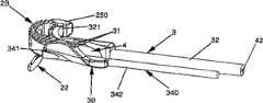
本发明的一些实施例的目标是通过提供在椎骨之间植入脊椎植入物(肌间融合器或椎间盘假体)和/或在这些椎骨中的至少一个椎骨中植入锚定装置的器械来克服一些以前设计的某些缺陷。该目标的多个或全部方面能通过在两块邻近的椎骨间植入脊椎植入物和在这些椎骨中的至少一个椎骨中植入锚定装置的器械来实现,这种器械首先包括至少一个具有头部的撞针(impactor),该头部的形状和尺寸被设计来推动锚定装置,并且所述器械其次包括沿纵轴线在第一端和第二端之间延伸的至少一个细长形的导杆,所述第一端被称为融合器或假体的抓握端,所述第二端被称为推动端,其中该抓握端包括用来与附连脊椎植入物的设备相配合的至少一个抓握设备,其特征是该导杆包括头部,其形状和尺寸被设计来至少部分地容纳撞针的头部并且其包括具有与根据本发明的一个实施例所述的锚定装置的曲率半径基本相同的曲率半径的至少一个引导表面,以便引导该锚定装置通过包括根据本发明的一个实施例所述的肌间融合器或根据本发明的一个实施例所述的椎间盘假体的脊椎植入物的孔,用于使锚定装置进入脊椎要被植入物植入其间的椎骨中的一个椎骨的椎骨表面内。Some embodiments of the present invention aim to implant a spinal implant (intermuscular fusion cage or intervertebral disc prosthesis) between vertebrae and/or implant an anchoring device in at least one of these vertebrae To overcome some of the shortcomings of some previous designs. Many or all aspects of this object can be achieved by an instrument for implanting a spinal implant between two adjacent vertebrae and for implanting an anchoring device in at least one of these vertebrae, the instrument first comprising at least one A striker (impactor) having a head shaped and dimensioned to push the anchoring device, and the instrument secondly includes at least one elongated impactor extending along the longitudinal axis between the first end and the second end. guide rod, the first end is called the grasping end of the cage or prosthesis, and the second end is called the pushing end, wherein the grasping end includes a device for attaching the spinal implant Cooperating at least one gripping device, characterized in that the guide rod comprises a head shaped and dimensioned to at least partially accommodate the head of the striker and which comprises an anchor with a at least one guiding surface having substantially the same radius of curvature of the anchoring device, so as to guide the anchoring device through an intermuscular fusion cage according to an embodiment of the present invention or an intervertebral disc according to an embodiment of the present invention A hole in the spinal implant of a prosthesis for the anchoring device to enter into the vertebral surface of one of the vertebrae between which the implant is to be placed.
根据一些实施例的另一个特征,所述导杆的头部包括腔体,该腔体的形状和尺寸被设计来接纳所述锚定装置及至少部分地接纳撞针的头部,所述导引表面包括至少两个弧形沟槽,弧形沟槽各位于该腔体的一个侧面上以便在其本体的两个侧面上引导锚定装置,同时撞针的头部从这些沟槽的一端到另一端穿到该腔体内。According to another feature in some embodiments, the head of the guide rod includes a cavity shaped and dimensioned to receive the anchoring device and at least partially the head of the striker, the guide The surface includes at least two arcuate grooves, each on one side of the cavity to guide the anchoring means on both sides of its body, while the head of the striker passes from one end of these grooves to the other. One end passes into the cavity.
根据一些实施例的另一个特征,所述撞针包括杆,当利用把手操作该杆时,该杆相对于所述导杆滑动。According to another feature of some embodiments, said striker comprises a rod which slides relative to said guide rod when the rod is manipulated by means of a handle.
根据一些实施例的另一个特征,所述撞针包括至少一个止动元件,该止动元件限制了撞针头部在导杆头部内的穿透。According to another feature of some embodiments, the striker comprises at least one stop element limiting the penetration of the head of the striker within the head of the guide rod.
根据一些实施例的另一个特征,所述抓握设备在抓握端伸出到导杆的头部之外,以便允许抓握融合器或假体,这种抓握是通过使得引导表面的一端开口在融合器或假体内的孔上从而被支持且引导表面的另一端保持可插入锚定装置而实现的。According to another feature in some embodiments, the grasping device protrudes beyond the head of the guide rod at the grasping end to allow grasping of the cage or prosthesis by making one end of the guide surface This is accomplished by opening over a hole in the cage or prosthesis so that it is supported and the other end of the guide surface remains insertable for the anchoring device.
根据一些实施例的另一个特征,所述附连设备是凹槽并且所述抓握设备是杆的一端,当用把手操作该杆时,该杆在导杆本体内滑动从而进入和离开融合器或假体的凹槽。According to another feature in some embodiments, the attachment device is a groove and the gripping device is an end of a rod that slides within the body of the guide rod to enter and exit the fusion cage when the rod is manipulated with a handle or prosthetic grooves.
根据一些实施例的另一个特征,所述杆包括装配到凹槽中的螺纹孔上的螺纹端,从而当用把手操作该杆时可确保融合器或假体固定。According to another feature of some embodiments, the rod includes a threaded end that fits onto a threaded hole in the groove, thereby ensuring fixation of the cage or prosthesis when the rod is manipulated with the handle.
根据一些实施例的另一个特征,所述附连设备是凹槽并且所述抓握设备是弯曲杆的一端,称为压舌板,该压舌板的曲率半径与其外围壁被勾勒成圆弧的融合器的曲率半径几乎相同,同时凹槽被设置在返回部件(return part)上,该返回部件在由壁所勾勒的圆弧构成的部件的圆心方向延伸由融合器的壁所勾勒的圆弧的一端,并且压舌板紧密装配到在该返回部件和由融合器的壁勾勒的圆弧的另一端之间的融合器的外形轮廓上,第二抓握设备设置在该另一端。According to another feature of some embodiments, said attachment device is a groove and said gripping device is an end of a curved rod, called a spatula, the radius of curvature of which is outlined with its peripheral wall in an arc of a circle The radius of curvature of the fusion cage is almost the same, while the groove is provided on the return part (return part), which extends the circle outlined by the wall of the fusion cage in the direction of the center of the part formed by the arc outlined by the wall one end of the arc, and the spatula fits tightly to the contour of the cage between the return part and the other end of the arc outlined by the cage wall, where the second gripping device is arranged.
根据一些实施例的另一个特征,所述第二抓握设备被设置在压舌板的基座上,但在与支撑压舌板相对的一侧上,并且其包括用来容纳安装在导杆的杆上的插销的第二凹槽,其中当用把手操作该杆时,该杆在插销插入第二凹槽内的至少一个位置和插销从第二凹槽取出并且因此释放融合器的位置之间枢转。According to another feature in some embodiments, the second gripping device is provided on the base of the spatula, but on the side opposite the supporting spatula, and includes a the second groove of the latch on the lever, wherein when the lever is operated with the handle, the lever is between at least one position where the latch is inserted into the second groove and a position where the latch is removed from the second groove and thus releases the cage Pivot between.
根据一些实施例的另一个特征,所述导杆的头部几乎沿融合器所勾勒的圆弧的曲率半径呈弧形或弯曲的。According to another feature in some embodiments, the head of the guide rod is arcuate or curved almost along the radius of curvature of the arc outlined by the fusion cage.
根据一些实施例的另一个特征,所述撞针的头部的外形轮廓几乎是弧形或弯曲的以便赋予该轮廓与其在导杆头部内的通道相符合的曲率半径,其中撞针的头部被安装到允许其枢转的旋转轴线上从而可经过在导杆头部处的弧形处或弯曲处。According to another feature in some embodiments, the profile of the head of the striker is almost arcuate or curved so as to give the profile a radius of curvature corresponding to its passage in the head of the guide rod, wherein the head of the striker is Mounted on an axis of rotation that allows it to pivot so as to pass through an arc or bend at the guide rod head.
本发明的一些实施例的目标是通过提供在椎骨间脊椎植入物的植入系统来克服一些以前设计的某些缺陷。该目标的多个或全部方面能通过在两个邻近的椎骨间脊椎植入物的植入系统实现,该系统包括至少一个脊椎植入物和在至少一块椎骨中锚定植入物的至少一个锚定装置,其特征是:It is an object of some embodiments of the present invention to overcome certain deficiencies of some previous designs by providing an implantation system for spinal implants between vertebrae. Several or all aspects of this object can be achieved by an implantation system of spinal implants between two adjacent vertebrae comprising at least one spinal implant and at least one of anchoring the implant in at least one vertebra. An anchoring device characterized by:
-脊椎植入物包括根据本发明的一个实施例所述的肌间融合器或根据本发明的一个实施例所述的椎间盘假体;以及- a spinal implant comprising an intermuscular fusion cage according to an embodiment of the invention or an intervertebral disc prosthesis according to an embodiment of the invention; and
-锚定装置包括根据本发明的一个实施例所述的锚定装置。- The anchoring device comprises an anchoring device according to an embodiment of the invention.
根据一些实施例的另一个特征,所述系统包括根据本发明的一个实施例所述的器械。According to another feature in some embodiments, the system includes an apparatus according to an embodiment of the invention.
本发明的一些实施例的目标是通过提供在椎骨之间脊椎植入物(肌间融合器或椎间盘假体)的植入方法来克服一些以前设计的某些缺点。It is an object of some embodiments of the present invention to overcome certain disadvantages of some previous designs by providing a method of implanting a spinal implant (intermuscular fusion cage or intervertebral disc prosthesis) between the vertebrae.
本目标的多个或全部方面能通过插入脊椎植入物的方法实现,其包括:Many or all aspects of this objective can be accomplished by methods of inserting spinal implants, including:
-提供根据本发明的锚定装置;- providing an anchoring device according to the invention;
-提供脊椎植入物,该脊椎植入物包括根据本发明的一个实施例所述的肌间融合器或根据本发明的一个实施例所述的椎间盘假体;- providing a spinal implant comprising an intermuscular fusion cage according to an embodiment of the invention or an intervertebral disc prosthesis according to an embodiment of the invention;
-提供根据本发明实施例的植入器械;- providing an implant device according to an embodiment of the invention;
-用植入器械的抓握装置来抓握脊椎植入物;- Grasping the spinal implant with the gripping device of the implant instrument;
-在脊柱的邻近椎骨之间的椎骨间隙中插入脊椎植入物;- Insertion of spinal implants in the intervertebral space between adjacent vertebrae of the spine;
-通过使得锚定装置的纵轴线沿着接近轴线来放置锚定装置,其中该接近轴线基本上沿着椎骨间隙的平面;- placing the anchoring device by making the longitudinal axis of the anchoring device along an approach axis, wherein the approach axis is substantially along the plane of the intervertebral space;
-使用植入器械的撞针,插入锚定装置使其通过植入器械的导杆头部和植入物中的孔,同时锚定装置横穿植入物的至少一部分;以及- using the striker of the implant device, inserting the anchoring device through the guide rod head of the implant device and the hole in the implant while the anchor device traverses at least a portion of the implant; and
-使用植入器械的撞针,在邻近的椎骨中的一个椎骨中植入锚定装置的穿透端。- Using the striker of the implant instrument, implant the penetrating end of the anchoring device in one of the adjacent vertebrae.
附图说明Description of drawings
在阅读下面描述并且参考附图,本发明各个实施例的其他特征和优点将变得更清楚,其中:Other features and advantages of various embodiments of the present invention will become more apparent upon reading the following description and referring to the accompanying drawings, in which:
-图1A表示根据本发明的一个实施例所述的锚定装置的透视图,图1B表示根据本发明的另一个实施例所述的锚定装置的俯视图,以及图1C和图1D表示根据本发明的两个不同的实施例所述的锚定装置的侧视图;- FIG. 1A shows a perspective view of an anchoring device according to one embodiment of the invention, FIG. 1B shows a top view of an anchoring device according to another embodiment of the invention, and FIGS. 1C and 1D show Side views of the anchoring device according to two different embodiments of the invention;
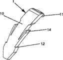
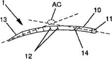
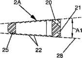
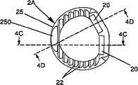
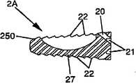
-图2A、图2B和图2D分别表示根据本发明的实施例所述的肌间融合器的透视图、俯视图和轮廓图,图2C表示沿图2B所示的剖面2C-2C上该肌间融合器的剖视图及图2E表示沿图2D所示的剖面2E-2E上该肌间融合器的剖视图;- Figure 2A, Figure 2B and Figure 2D respectively represent a perspective view, a top view and a profile view of the intermuscular fusion device according to an embodiment of the present invention, and Figure 2C represents the intermuscular fusion device along the
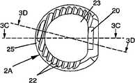
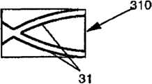
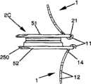
-图3A和图3B分别表示根据本发明的一个实施例所述的肌间融合器的前透视图和俯视图,图3C表示沿着图3B所示的剖面3C-3C的该肌间融合器的剖视图及图3D表示沿着图3B所示的剖面3D-3D的该肌间融合器的剖视图;- Figures 3A and 3B respectively represent a front perspective view and a top view of an intermuscular fusion device according to an embodiment of the present invention, and Fig. 3C represents a view of the intermuscular fusion device along the
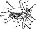
-图4A和图4B分别表示根据本发明的一个实施例所述的肌间融合器的前透视图和俯视图,图4C表示沿着图4B所示的剖面4C-4C的该肌间融合器的剖视图,以及图4D表示沿着图4B所示的剖面4D-4D的该肌间融合器的剖视图;- Figures 4A and 4B respectively represent a front perspective view and a top view of an intermuscular fusion device according to an embodiment of the present invention, and Fig. 4C represents a view of the intermuscular fusion device along the
-图5A和图5B分别表示根据本发明的一个实施例所述的锚定装置植入导杆的头部的透视图和前视图,图5C和图5D分别表示根据本发明的一个实施例所述的锚定装置的引导元件的透视图和侧视图以及图5E表示用根据本发明的一个实施例所述的两个引导元件装备的导杆头部的前视图;- Figures 5A and 5B respectively represent a perspective view and a front view of the head of an anchoring device implanted guide rod according to an embodiment of the present invention, and Fig. The perspective view and side view of the guiding element of the anchoring device described above and Figure 5E represent the front view of the guide rod head equipped with two guiding elements according to one embodiment of the present invention;
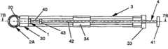
-图6A表示根据本发明的一个实施例所述的植入导杆和撞针的透视图,图6B、图6C和图6D分别表示根据本发明的一个实施例所述的植入导杆的俯视图、沿着图6B所示剖面6C-6C的植入导杆的剖试图和沿着图6C所示剖面6D-6D的植入导杆的剖视图,以及图6E表示根据本发明的一个实施例所述的撞针的侧视图;- Fig. 6A shows a perspective view of an implant guide rod and a striker according to an embodiment of the present invention, and Fig. 6B, Fig. 6C and Fig. 6D respectively represent a top view of an implant guide rod according to an embodiment of the present invention , a cross-sectional view of an implant guide rod along
-图7A和图7C分别表示即将被嵌入和已被嵌入的植入导杆、撞针、融合器及锚定装置的根据本发明的一个实施例所述的组装装置的俯视图,图7B和图7D分别表示沿着图7A所示的剖面7B-7B和沿着图7C所示的剖面7D-7D的该组装装置的剖视图;- Fig. 7A and Fig. 7C respectively represent the top view of the assembly device according to an embodiment of the present invention of the implant guide rod, striker, fusion device and anchoring device which are about to be embedded and have been embedded, Fig. 7B and Fig. 7D Respectively represent cross-sectional views of the assembled device along
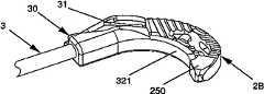
-图8A和图8B分别表示用根据本发明的一个实施例所述的锚定装置装备的肌间融合器的透视图以及图8C表示装有根据本发明的一个实施例所述的肌间融合器的植入导杆一端的透视图;- Figures 8A and 8B respectively represent perspective views of an intermuscular fusion device equipped with an anchoring device according to an embodiment of the present invention and Figure 8C represents an intermuscular fusion device equipped with an intermuscular fusion device according to an embodiment of the present invention A perspective view of one end of the implant guide rod of the device;
-图9A和图9B分别表示装有用根据本发明的一个实施例所述的锚定装置装备的肌间融合器的植入导杆一端的透视图和俯视图以及图9C表示图9B所示的剖面9C-9C的剖视图;- Figures 9A and 9B represent respectively a perspective view and a top view of one end of an implantation guide equipped with an intermuscular fusion device equipped with an anchoring device according to an embodiment of the present invention and Fig. 9C represents a section as shown in Fig. 9B Sectional view of 9C-9C;
-图10A、图10B和图10C分别表示支撑的肌间融合器的一个实施例的透视图、俯视图和沿图10B的轴线10C-10C的剖视图以及图10D、图10E和图10F分别表示支撑的肌间融合器的另一个实施例的透视图、俯视图和沿着图10E的轴线10F-10F的剖示图;- Figure 10A, Figure 10B and Figure 10C respectively represent a perspective view, a top view and a cross-sectional view along the axis 10C-10C of Figure 10B of an embodiment of a supported intermuscular fusion device and Figure 10D, Figure 10E and Figure 10F respectively represent a supported Perspective, top and cross-sectional views along axis 10F-10F of FIG. 10E of another embodiment of an intermuscular fusion device;
-图11A和图11B分别表示用锚定装置装备的椎间盘假体的一个实施例的透视图和侧视图,以及图11C和图11D分别表示用锚定装置装备的椎间盘假体的另一个实施例的透视图和侧视图。- Figures 11A and 11B represent a perspective view and a side view, respectively, of one embodiment of an intervertebral disc prosthesis equipped with an anchoring device, and Figures 11C and 11D represent, respectively, another embodiment of an intervertebral disc prosthesis equipped with an anchoring device perspective and side views.
具体实施方式Detailed ways
此外,本发明涉及锚定装置(1),该锚定装置是大致弧形并且用于脊椎植入物例如脊椎融合器(2A、2B)或椎间盘假体(2C)。在各种实施例中,所述锚定装置(1)可以是刚性的并且与设置在其固定的融合器(2A、2B)或假体(2C)上的孔或槽(20)配合。一般地,该孔或槽能被调整为沟槽来接纳锚定装置(1),但是本领域的技术人员将会意识到本发明为所述的锚定装置和所述的孔或槽(本文用其延伸含义)提供了多种形状并且意识到本文所用的术语“孔”、“槽”以及“沟槽”不应该被看作限制本发明的范围。此外,本发明还涉及脊椎融合器(2A、2B)和椎间盘假体(2C),在各种实施例中其可能有适于接纳锚定装置(1)的沟槽(20)或其他孔或槽。此外,本发明还涉及植入脊椎融合器(2A、2B)或椎间盘假体(2C)的器械和植入锚定装置来牢固固定融合器(2A、2B)或椎间盘假体(2C)的器械。在各种实施例中,所述器械是为锚定装置(1)而设计的以便在椎骨中固定该锚定装置并且还固定肌间融合器(2A、2B)或椎间盘假体(2C),该肌间融合器(2A、2B)或椎间盘假体(2C)包括保持或附连植入器械的至少一个构件(24),以便允许这些构件通过该器械被抓握或啮合。该附连装置(attachment device)可以包括可容纳该器械的至少一个抓握装置(321)的至少一个凹槽(24),如图所示且下面将详细描述。但是,这个附连设备(24)还可包括在融合器或假体的外部上凸出的部分并且该部分被插入到抓握设备(未示出)的凹槽内。另外,在某些实施变型中,这个附连设备(24)可至少部分地由融合器(2A、2B)或椎间盘假体(2C)的不同表面构成,该器械的抓握设备(321)于是具有与这些表面互补的外形轮廓以便允许抓握融合器或假体。Furthermore, the invention relates to an anchoring device (1) which is substantially arc-shaped and is used for spinal implants such as spinal fusion cages (2A, 2B) or intervertebral disc prosthesis (2C). In various embodiments, said anchoring device (1 ) may be rigid and cooperate with holes or slots (20) provided on the cage (2A, 2B) or prosthesis (2C) to which it is fixed. Generally, this hole or slot can be adapted as a groove to receive the anchoring device (1), but those skilled in the art will realize that the present invention is a combination of said anchoring device and said hole or slot (herein By its extension) a variety of shapes are provided and it is recognized that the terms "hole", "slot" and "trench" as used herein should not be viewed as limiting the scope of the invention. Furthermore, the invention relates to spinal fusion cages (2A, 2B) and intervertebral disc prosthesis (2C), which in various embodiments may have grooves (20) or other holes or holes adapted to receive anchoring means (1) groove. Furthermore, the present invention also relates to an instrument for implanting a spinal fusion cage (2A, 2B) or an intervertebral disc prosthesis (2C) and an instrument for implanting an anchoring device to firmly fix the fusion cage (2A, 2B) or an intervertebral disc prosthesis (2C) . In various embodiments, said instrument is designed for the anchoring device (1) in order to fix the anchoring device in the vertebrae and also to fix the intermuscular fusion (2A, 2B) or intervertebral disc prosthesis (2C), The intermuscular fusion cage (2A, 2B) or intervertebral disc prosthesis (2C) includes at least one member (24) holding or attaching implanted instruments so as to allow these members to be grasped or engaged by the instrument. The attachment device may comprise at least one recess (24) receivable at least one gripping device (321 ) of the instrument, as shown and described in detail below. However, this attachment device (24) may also comprise a portion protruding on the outside of the cage or prosthesis and which is inserted into a groove of the gripping device (not shown). Furthermore, in some implementation variants, this attachment device (24) may be constituted at least in part by different surfaces of the fusion cage (2A, 2B) or the intervertebral disc prosthesis (2C), the gripping device (321) of this instrument then The contours are complementary to these surfaces to allow gripping of the fusion cage or prosthesis.
各种实施例允许该装置和相关器械尺寸的减小,从而允许在基本上是沿着椎骨间隙(盘间隙)的平面的接近轴线上植入锚定装置。如下所述即使当锚定装置试图沿着斜轴线植入,尺寸的减小也是特别有利的。本发明的各种实施例通过用在脊椎植入物(2A、2B、2C)中横穿该植入物至少一部分的孔(20)轻松植入锚定装置(1),且该锚定装置的尺寸和曲率半径以这种方式被设计,即该锚定装置(1)通过无变形地被插入通过孔(20)而被植入到椎骨表面内,该孔(20)的形状、尺寸和取向被设置成允许锚定装置(1)尽管其有弯曲但没有变形地通过,因此该锚定装置(1)穿到至少一块椎骨表面内并且在这个椎骨表面上固定脊椎植入物。因此,本发明的这些实施例使用具有弧形本体的锚定装置,该弧形本体适于自由穿过其试图固定的脊椎植入物的接纳孔。因此,弧形锚定装置尽管其有弧形轮廓但没有变形地自由通过所述孔,有利于其植入到椎骨中。因此,在各种实施例中锚定装置可以是基本刚性的。Various embodiments allow for a reduction in size of the device and associated instrumentation, thereby allowing implantation of the anchoring device on an approach axis substantially along the plane of the intervertebral space (disc space). The reduction in size is particularly advantageous even when the anchoring device is intended to be implanted along an oblique axis, as described below. Various embodiments of the present invention facilitate implantation of the anchoring device (1) by use of a hole (20) in a spinal implant (2A, 2B, 2C) traversing at least a portion of the implant, and the anchoring device The size and radius of curvature are designed in such a way that the anchoring device (1) is implanted in the vertebral surface by being inserted through the hole (20) without deformation, the shape, size and The orientation is set to allow passage of the anchoring device (1) despite its curvature without deformation, whereby the anchoring device (1) penetrates into at least one vertebral surface and secures the spinal implant on this vertebral surface. Accordingly, these embodiments of the present invention utilize anchoring devices having an arcuate body adapted to pass freely through the receiving aperture of the spinal implant it is attempting to secure. Thus, the curved anchoring device passes freely through the hole without deformation despite its curved profile, facilitating its implantation into the vertebrae. Thus, in various embodiments the anchoring device may be substantially rigid.
锚定装置(1)还可包括沿纵轴线在第一端和第二端之间延伸的细长形本体(10)。在本描述中,第一端称为穿透端且第二端称为对接端。各种实施例的锚定装置(1)的本体(10)可有弧形轮廓,该轮廓沿着纵轴线勾勒成弧形,例如圆弧或椭圆弧,其尺寸和曲率半径(或半径)以如下方式被设计,即锚定装置(1)通过使得装置(1)的纵轴线近似沿着椎骨间隙的平面而被植入到椎骨的椎板内。各种实施变型具有的锚定装置(1)可具有不同的曲率半径(或半径)。该装置在本体(10)的不同部分上还可具有多种不同的曲率半径,或可具有沿本体(10)变化的曲率半径。因此,该本体可有,例如圆弧或椭圆弧的外形轮廓,但是也可勾勒成更复杂的曲线,例如是具有相同曲率半径或不同曲率半径的多个圆弧首尾连接在一起或者是具有相同曲率半径或不同曲率半径的多个椭圆弧首尾连接在一起,甚至是其的任意组合,甚至是沿主体的位置的函数的曲率半径。在本描述中,术语“弧”、“圆弧”以及“曲率半径”对应于所有这些可能性。The anchoring device (1) may further comprise an elongated body (10) extending along the longitudinal axis between the first end and the second end. In this description, the first end is called the penetration end and the second end is called the butt end. The body (10) of the anchoring device (1) of various embodiments may have an arcuate profile, which outlines an arc along the longitudinal axis, such as a circular arc or an elliptical arc, with dimensions and a radius of curvature (or radius) of The anchoring device (1) is designed in such a way that the longitudinal axis of the device (1) is approximately along the plane of the intervertebral space to be implanted in the lamina of the vertebrae. Various implementation variants have the anchoring device ( 1 ) having different radii (or radii) of curvature. The device may also have multiple different radii of curvature on different parts of the body (10), or may have a radius of curvature that varies along the body (10). Thus, the body may have, for example, a circular or elliptical arc profile, but may also outline more complex curves, such as a plurality of circular arcs with the same or different radii of curvature connected end to end or with the same Multiple elliptical arcs of radii of curvature or different radii of curvature joined together end to end, or even any combination thereof, even radii of curvature as a function of position along the body. In this description, the terms "arc", "arc" and "radius of curvature" correspond to all these possibilities.
因此,本发明的一些实施例提供了与锚定装置(1)的曲率半径(或半径)相关的不同的实施变型。例如,根据该装置(1)及特别是在其间植入融合器或假体的椎骨的装置的使用,该装置(1)优选地可具有在各种间隙中较大或较小尺寸的曲率半径。例如,根据预期用途该半径可能大小不一。根据锚定装置(1)的曲率半径,分别通过该装置(1)的穿透端和对接端的轴线形成角度(AC),特别地在图1C和图1D中可以看出。虽然该角度(AC)通常将会在90°到180°的范围内,但其也可选择小于90°的角度。该角度(AC)优选是处在110°和160°之间,在许多情况下在该角度范围内比超出这个范围能更有利于该设备的植入。根据期望的固定设置,角度(AC)的选择可以几乎是开放的。例如,如果想要通过使其牢固地紧贴靠椎板来固定该融合器或假体,则角度(AC)能在120°到180°的范围内选择,而如果相反想要固定融合器或假体以便防止其在椎间盘间隙的平面内的运动,则角度(AC)能在90°到150°之间选择。不同的实施变型可为锚定装置(1)提供不同角度来固定融合器或假体。例如在一个优选实施例中,角度(AC)可有例如接近135°的相互适合值,来通过使融合器或假体紧贴靠紧椎板以固定该装置并且阻止融合器或假体在椎间盘间隙的平面内的运动。Therefore, some embodiments of the invention provide different implementation variants related to the radius of curvature (or radius) of the anchoring device (1). For example, depending on the use of the device (1) and in particular the vertebrae between which a cage or prosthesis is implanted, the device (1) may preferably have a radius of curvature of larger or smaller size in various gaps . For example, the radius may vary depending on the intended use. Depending on the radius of curvature of the anchoring device (1 ), the axes passing through the penetrating end and the butt end of the device (1 ), respectively, form an angle (AC), as can be seen in particular in Figures 1C and ID. Although this angle (AC) will generally be in the range of 90° to 180°, it may also be chosen to be less than 90°. The angle (AC) is preferably between 110[deg.] and 160[deg.], and in many cases the implantation of the device is more favorable within this range than outside this range. Depending on the desired fixed setting, the choice of angle (AC) can be almost open. For example, if one wants to fix the fusion cage or prosthesis by making it firmly against the lamina, the angle (AC) can be selected in the range of 120° to 180°, and if instead one wants to fix the fusion cage or prosthesis In order to prevent the prosthesis from moving in the plane of the intervertebral disc space, the angle (AC) can be chosen between 90° and 150°. Different implementation variants may provide different angles for the anchoring device ( 1 ) to fix the cage or prosthesis. For example, in a preferred embodiment, the angle (AC) can have a mutual fit value, such as close to 135°, to fix the device by holding the fusion cage or prosthesis tightly against the lamina and prevent the fusion cage or prosthesis from resting on the intervertebral disc. Motion in the plane of the gap.
另外,根据融合器或假体的实施例,不管是自然脊柱前凸或病理性脊柱前凸(pathological lordosis)或由假体所造成的前凸,该装置均可以选择不同的角度,主要是促进牢固安装。锚定装置(1)可被插入通过沟槽(20),该沟槽设置在融合器(2A、2B)的至少一个外围壁上或椎间盘假体(2C)的至少一个板上,并且横穿该融合器(2A、2B)或假体(2C)的至少一部分。该沟槽(20)可从融合器(2A、2B)的壁(25)的外围表面或从假体(2C)的板的外围表面延伸到该融合器(2A、2B)或该板的上表面或下表面,且具有为锚定装置(1)曲率半径设计的取向,从而在其间植入融合器(2A、2B)或假体的椎骨中的一块椎骨的椎板方向上定向该锚定装置。利用沟槽(20)的这个取向,锚定装置(1)可穿到至少一个椎板内并且紧靠该椎板固定融合器(2A、2B)或假体(2C)。取决于锚定装置(1)的曲率半径和角度(AC),根据不同的实施例,沟槽(20)的厚度和方向可不同。In addition, depending on the embodiment of the cage or prosthesis, the device can choose different angles whether it is natural lordosis or pathological lordosis or lordosis caused by the prosthesis, mainly to facilitate Install securely. The anchoring device (1) can be inserted through a groove (20) provided on at least one peripheral wall of the cage (2A, 2B) or at least one plate of the intervertebral disc prosthesis (2C) and across At least a portion of the fusion cage (2A, 2B) or prosthesis (2C). The groove (20) may extend from the peripheral surface of the wall (25) of the cage (2A, 2B) or from the peripheral surface of the plate of the prosthesis (2C) to the cage (2A, 2B) or the plate surface or subsurface, and has an orientation designed for the radius of curvature of the anchoring device (1), thereby orienting the anchor in the direction of the lamina of one of the vertebrae between which the fusion cage (2A, 2B) or prosthesis is implanted device. With this orientation of the groove (20), the anchoring device (1) can penetrate into at least one lamina and fix the fusion cage (2A, 2B) or the prosthesis (2C) against this lamina. Depending on the radius of curvature and angle (AC) of the anchoring device (1), the thickness and orientation of the grooves (20) may vary according to different embodiments.
因此本发明的一些实施例提供了肌间融合器(2A、2B),该肌间融合器包括形成接纳骨组织移植物或替代物的腔体(23)的外围壁(25)。如图所示,这样的融合器可包括在其中心由其壁(25)形成的腔体(23),但是在其他实施变型中,该融合器还可由在其内部没有腔体的机体(block)组成,例如从以前的设计可知这样的融合器至少是成对使用以便在融合器之间形成腔体。在图10A所表示的实施变型中,肌间融合器(2A)包括从一侧到另一侧横穿其腔体(23)的支架(27)(brace),该支架(27)可被配置来加固融合器(2A)的壁(25)。这个支架(27)可具有不同的形式和取向,并且例如可被定向成在椎骨之间沿着融合器(2A)的插入轴线。在各种实施例中,支架(27)可有小于融合器其余部分的高度。支架(27)相对于融合器其余部分具有的较小高度可允许融合器环抱具有任何不规则外形轮廓的椎板。因此,例如如图10A到图10C所述,支架(27)的上表面和下表面分别位于比融合器(2A)的上表面和下表面较低和较高的位置。因此,如果两块邻近椎骨的椎板具有隆起物,则融合器将遵循这些板的外形并且通常提供了更好的稳定性。在图10A到图10C所示的这个实施方式中,支架没有槽口因为其将不会与椎板相接触。但是,例如即使在这种情况下,该支架(27)仍可具有槽口(22),以便当骨质移植物已经围绕融合器生长时可增加融合器的稳定性。在图10D到图10F的实施方式中,支架(27)的下表面与融合器(2A)其余部分的下表面位于同一水平面上,而支架(27)的上表面位于比融合器(2A)其余部分的上表面较低的位置,具体地如图10E可以看出。在这个实施方式中,支架(27)的下表面装备有槽口(22)且在融合器的其余部分也具有槽口从而可限制融合器的运动。在一个变型中,这个支架可能不包括槽口。在一个变型中,这种类型的融合器还可被用在相对于该示例的相反的构型(inverse configuration)中。因此,在这个变型中,支架(27)将具有与融合器其余部分的上表面在同一水平面上的上表面和位于比融合器其余部分较高的下表面。支架的所有可能的变型可自然地包括与融合器的其他特征有关的其他变型。Some embodiments of the present invention therefore provide an intermuscular fusion (2A, 2B) comprising a peripheral wall (25) forming a cavity (23) for receiving a bone tissue graft or substitute. As shown, such a cage may comprise a cavity (23) in its center formed by its walls (25), but in other implementation variants the cage may also consist of a block without a cavity inside it. ) composition, for example from previous designs it is known that such cages are used at least in pairs to form a cavity between the cages. In the implementation variant shown in Figure 10A, the intermuscular fusion device (2A) includes a bracket (27) (brace) that traverses its cavity (23) from one side to the other side, and the bracket (27) can be configured To reinforce the wall (25) of the cage (2A). This bracket (27) can have different forms and orientations and can for example be oriented between the vertebrae along the insertion axis of the cage (2A). In various embodiments, the bracket (27) may have a height that is less than the rest of the cage. The small height of the frame (27) relative to the rest of the cage allows the cage to embrace the lamina with any irregular contour. Thus, for example, as shown in FIGS. 10A to 10C , the upper and lower surfaces of the stent ( 27 ) are positioned lower and higher, respectively, than the upper and lower surfaces of the cage ( 2A ). Therefore, if the lamina of two adjacent vertebrae have humps, the cage will follow the shape of those plates and generally provide better stability. In this embodiment shown in Figures 10A-10C, the bracket has no notches because it would not be in contact with the lamina. However, even in this case, for example, the bracket (27) can still have notches (22) in order to increase the stability of the cage when the bone graft has grown around it. In the embodiment of Fig. 10D to Fig. 10F, the lower surface of the bracket (27) is located on the same level as the lower surface of the rest of the cage (2A), while the upper surface of the bracket (27) is located on a lower surface than the rest of the cage (2A). The lower part of the upper surface can be seen specifically in Figure 10E. In this embodiment, the lower surface of the bracket (27) is equipped with notches (22) and also in the rest of the cage so as to limit the movement of the cage. In a variation, this bracket may not include notches. In a variant, this type of fuser can also be used in an inverse configuration relative to this example. Thus, in this variant, the bracket (27) will have an upper surface at the same level as the upper surface of the rest of the cage and a lower surface situated higher than the rest of the cage. All possible variants of the scaffold may naturally include other variants in relation to other features of the cage.
在本发明的一些实施例中,融合器(2A、2B)的壁(25)包括至少一个沟槽(20),该沟槽具有尽管允许锚定装置(1)弯曲但仍能通过的宽度。为了允许锚定装置通过,这个沟槽(20)可有基本上大于锚定装置(1)高度的宽度(由沟槽所表示的孔隙的高度)。这个沟槽(20)横穿在壁(25)的外围表面和融合器(2A、2B)的上表面或下表面之间的融合器(2A、2B),且具有为锚定装置(1)的曲率半径所设计的取向,以便沿其间植入融合器(2A、2B)的椎骨中的一块椎骨的椎板方向定向该锚定装置。In some embodiments of the invention, the wall (25) of the cage (2A, 2B) comprises at least one groove (20) having a width that allows the anchoring device (1) to pass through despite bending. In order to allow the passage of the anchoring means, this groove (20) may have a width (height of the aperture represented by the groove) substantially greater than the height of the anchoring means (1). This groove (20) traverses the cage (2A, 2B) between the peripheral surface of the wall (25) and the upper or lower surface of the cage (2A, 2B) and has the function of anchoring means (1) The orientation of the radius of curvature is designed so as to orient the anchoring device along the laminar direction of one of the vertebrae between which the fusion cage (2A, 2B) is implanted.
本发明的一些实施例提供了椎间盘假体(2C)。该假体(2C)包括沿着弧形表面铰接的至少一个第一板(51)和一个第二板(52)。在一个实施例中,特别地在图11A和图11B中可以看出,假体(2C)仅包括两个具有弧形表面的板(51,52)。该两个板(51,52)的这些弧形表面是互补的并且匹配在一起以便通过绕轴线旋转或相对彼此倾斜所述板而允许板(51,52)具有关节/铰接处(articulation),其中所述轴线与所述板的平面几乎垂直。特别地在图11C和图11D中可以看出的另一个实施例中,假体(2C)包括两个板(51,52)和中部核芯(centralcore)(53),该中部核芯相对于板(51,52)中的至少一个板是可活动的。在一个实施例中,这个核芯(53)包括基本上是平面且匹配到一个板(51,52)的基本平面的表面上的表面以及弧形表面,该弧形表面匹配到另一个板(52,51)的互补的弧形表面上。该弧形表面允许以前所述的(倾斜和/或旋转)关节连接,并且该平面表面允许核芯相对于包括平面表面的板的线形运动和/或核芯相对于该板围绕与板的平面几乎垂直的轴线旋转。另外,根据所用的实施例,核芯(53)可包括在至少一个板(51,52)上的互补的配合设备(530),以便限制核芯(53)相对于这个板的旋转运动和/或线形运动。在本发明的一些实施例中,假体(2C)的至少一个板(51,52)包括至少一个沟槽(20),该沟槽具有允许锚定装置(1)尽管弯曲但仍能通过的宽度。这个沟槽(20)可具有基本上大于锚定装置(1)高度的宽度(沟槽所勾勒的孔隙的高度)。与如上所述的具有肌间融合器(2A、2B)的一些实施例类似,椎间盘假体(2C)可具有一个或多个沟槽(20),该沟槽横穿板(51,52)且沿其间植入假体(2C)的椎骨中的一块椎骨的椎板方向定向锚定装置(1)。在一些实施例中,沟槽(20)的尺寸和取向可分别与锚定装置(1)的尺寸和曲率半径相适合。Some embodiments of the invention provide an intervertebral disc prosthesis (2C). The prosthesis (2C) comprises at least a first plate (51) and a second plate (52) hinged along arcuate surfaces. In one embodiment, as can be seen particularly in Figures 11A and 11B, the prosthesis (2C) comprises only two plates (51, 52) with curved surfaces. The arcuate surfaces of the two plates (51, 52) are complementary and fit together to allow the plates (51, 52) to have articulations by rotating about an axis or tilting the plates relative to each other, wherein said axis is almost perpendicular to the plane of said plate. In another embodiment, which can be seen especially in Fig. 11C and Fig. 11D, the prosthesis (2C) comprises two plates (51, 52) and a central core (53) relative to the At least one of the plates (51, 52) is movable. In one embodiment, this core (53) comprises a surface that is substantially planar and fits onto the substantially planar surface of one plate (51, 52) and an arcuate surface that fits to the other plate ( 52, 51) on the complementary curved surfaces. The arcuate surface allows the previously described (tilt and/or rotation) articulation, and the planar surface allows linear movement of the core relative to the plate comprising the planar surface and/or the core relative to the plate around the plane of the plate Almost vertical axis of rotation. In addition, depending on the embodiment used, the core (53) may comprise complementary cooperating devices (530) on at least one plate (51, 52) in order to limit the rotational movement of the core (53) relative to this plate and/or or linear motion. In some embodiments of the invention, at least one plate (51, 52) of the prosthesis (2C) comprises at least one groove (20) having a groove allowing passage of the anchoring device (1) despite bending. width. This groove ( 20 ) may have a width (height of the aperture delineated by the groove) substantially greater than the height of the anchoring device ( 1 ). Similar to some embodiments described above with intermuscular cages (2A, 2B), the disc prosthesis (2C) may have one or more grooves (20) that traverse the plates (51, 52) And the anchoring device (1) is oriented in the direction of the laminae of one of the vertebrae between which the prosthesis (2C) is implanted. In some embodiments, the size and orientation of the groove (20) may be adapted to the size and radius of curvature of the anchoring device (1 ), respectively.
在本发明的优选实施例中,沟槽(20)的宽度将稍大于锚定装置(1)的厚度,足以允许锚定装置在沟槽内通过,但是通过锚定装置(1)仅稍微增加融合器(2A、2B)或假体(2C)的保持力,而在沟槽(20)内锚定装置没有过大的间隙。在各种实施例中,装置(1)沿着对接端的曲线可被配置为与沟槽(20)相干涉(配合)以便通过锚定装置(1)充分地增加融合器(2A、2B)或假体(2C)的保持力。在本发明的某些实施例中,沟槽(20)的长度可基本与装置(1)的宽度相同,因此一旦锚定装置被插入沟槽(20)内则会有很小的或没有间隙。锚定装置(1)的长度可被设计以用于被横穿的沟槽(20)的深度并且被设计成该装置必须穿透椎板的深度。In a preferred embodiment of the invention, the width of the groove (20) will be slightly greater than the thickness of the anchoring device (1), sufficient to allow passage of the anchoring device within the groove, but only slightly increased by the anchoring device (1). The retention force of the fusion cage (2A, 2B) or prosthesis (2C) without excessive play of the anchoring device in the groove (20). In various embodiments, the curve of the device (1) along the butt end can be configured to interfere (fit) with the groove (20) to substantially augment the cage (2A, 2B) or Retention of the prosthesis (2C). In some embodiments of the invention, the length of the groove (20) may be substantially the same as the width of the device (1), so that there is little or no gap once the anchoring device is inserted into the groove (20) . The length of the anchoring device (1) can be designed for the depth of the groove (20) to be traversed and to the depth to which the device must penetrate the lamina.
因此,锚定装置(1),利用其曲率半径和其所插入的沟槽(20)的取向,可沿接近轴线被植入,该接近轴线基本沿椎骨间隙的平面,即沿着融合器(2A、2B)或假体(2C)被植入的平面,锚定装置的这种植入方式有利于椎间盘假体或融合器的所有元件和锚定装置接近椎骨间隙的边缘。在一个实施例中,本体(10)所勾勒的弧形的尺寸和曲率半径被设计成使得锚定装置(1)可沿与脊柱的垂直轴线成40°和140°之间的角度且优选地是大约90°的角度的接近轴线被植入到椎板内。对于给定的锚定装置(1),根据椎骨边缘的尺寸该角度可不同,并且根据所用装置(1)的曲率半径和在其对接端和穿透端之间形成的角度(AC),不同的锚定装置(1)的角度也可不同。Thus, the anchoring device (1), by virtue of its radius of curvature and the orientation of the groove (20) into which it is inserted, can be implanted along an approximate axis substantially along the plane of the intervertebral space, i.e. along the cage ( 2A, 2B) or the plane in which the prosthesis (2C) is implanted, this implantation of the anchoring device facilitates the proximity of all elements of the intervertebral disc prosthesis or cage and the anchoring device to the edge of the intervertebral space. In one embodiment, the arc traced by the body (10) is dimensioned and the radius of curvature is designed such that the anchoring device (1) can be positioned at an angle of between 40° and 140° to the vertical axis of the spine and preferably The approximation axis, which is an angle of approximately 90°, is implanted into the lamina. For a given anchoring device (1), this angle can vary depending on the size of the vertebral edge, and can vary depending on the radius of curvature of the device (1) used and the angle (AC) formed between its abutting and penetrating ends. The angle of the anchoring device (1) can also be different.
在本发明的一个实施例中,具体地在图1(A到D)中可以看出,弧形的且细长的本体(10)包括至少一个弧形板。如图所示这个板可以是基本矩形的,但在没有超出本发明的原理的情况下可自然地有多种形状。同样地,在其他的实施变型中,本体(10)可包括弧形杆,且沟槽(20)具有与这个杆的区段相配合的外形轮廓,不过自然本发明允许其他实施例,特别是关于本体(10)的外形轮廓允许其他实施例。在其他实施变型中(未示出),这个锚定装置(1)的本体(10)可包括两个板(或两个杆),该板或杆通常相互平行且通过安装到融合器或假体中的沟槽(20)中心的杆的内弯部分在对接端被连接在一起,例如,如申请FR2827156(或WO03/005939)和FR2879436(或WO2006/120505)所示和所述的平锚,通过参考合并于此。In one embodiment of the invention, as can be seen in particular in Figures 1 (A to D), the curved and elongated body (10) comprises at least one curved plate. This plate may be substantially rectangular as shown, but may naturally have a variety of shapes without departing from the principles of the invention. Likewise, in other implementation variants, the body (10) may comprise an arcuate rod, and the groove (20) has a profile adapted to a section of this rod, although of course the invention allows other embodiments, in particular Other embodiments are allowed with respect to the profile of the body (10). In other implementation variants (not shown), the body (10) of this anchoring device (1) may comprise two plates (or two rods) generally parallel to each other and mounted to a fusion cage or dummy. The inwardly bent parts of the rods in the center of the groove (20) in the body are joined together at the butt ends, for example flat anchors as shown and described in applications FR2827156 (or WO03/005939) and FR2879436 (or WO2006/120505) , incorporated herein by reference.
锚定装置(1)的穿透端穿到在其间植入融合器(或假体)的椎骨中的一块椎骨的椎板内。在本发明的一个实施例中,该穿透端包括有利于装置(1)穿到椎骨内的倒角(13)或斜角,具体地在图1C和图1D中可以看出。在一个实施变型中,例如如图1B所示,这个穿透端还可包括V-形槽形式的凹口(15),从而有利于穿透端穿到椎板内。对接端邻接抵靠该装置所固定的融合器或假体的表面,从而更加稳固地和牢固地保持锚定装置抵靠椎板。The penetrating end of the anchoring device (1) penetrates into the lamina of one of the vertebrae between which the cage (or prosthesis) is implanted. In one embodiment of the invention, the penetrating end comprises a chamfer (13) or bevel to facilitate penetration of the device (1) into the vertebrae, as can be seen in particular in Figures 1C and ID. In an implementation variant, such as shown in FIG. 1B , this penetrating end may also include a notch ( 15 ) in the form of a V-shaped groove, thereby facilitating the penetrating end's penetration into the lamina. The abutting end abuts against the surface of the cage or prosthesis to which the device is secured, thereby more firmly and securely holding the anchoring device against the lamina.
在锚定装置(1)的不同的实施变型中,本体(10)的对接端包括至少一个止动元件(11),该止动元件与装置(1)所固定的融合器(2A、2B)或假体(2C)的至少一个表面相配合。用一种互补方式,在融合器(2A、2B)或假体(2C)的不同的实施变型中,在壁(25)的外围表面的水平面上,沟槽(20)包括与锚定装置(1)的至少一个止动元件(11)相配合的至少一个止动元件表面(21)。在一个实施例中,具体地在图1A和图1D中可看出,止动元件(11)包括在锚定装置(1)的至少一个面上的凸耳。在所示的示例中,这个止动元件仅包括面向本体(10)所勾勒的弧形构成部分的圆的内部的凸耳,但是该凸耳可采用不同取向。于是融合器(2A、2B)或假体(2C)可仅包括在沟槽(20)下方的、这个止动元件(11)的接触表面。于是融合器(2A、2B)或假体(2C)的止动元件表面(21)可包括用来容纳锚定装置(1)的本体(10)的至少一个面上的凸耳的壁(25)或板(51,52)的外围表面。具体地在图1B和图1C可看出的另一个实施例中,止动元件(11)包括在本体(10)侧面上的两个凸耳。这两个凸耳可由被卡配(click-fitted)到沟槽内的两个插销(latch)组成。在这个实施例中,例如融合器(2A、2B)或假体(2C)的止动元件表面(21)可以包括位于沟槽(20)任一侧面上的两个凹口(21)以用来容纳锚定装置(1)的本体(10)侧面上的两个凸耳。例如这两个凹口可有适合卡配锚定装置(1)的凸耳的外形和尺寸。另外,具体地在图11A和图11C中可看出,板的外围在沟槽水平面上形成了开口以插入锚定装置并且位于这个开口和板的外围之间的边缘形成了一种杆,锚定装置(1)的止动元件(11)可安装在这种杆上。因此,装置(1)的止动元件(11)可由被卡配到板边缘上的弧形部分组成。因此,在装置(1)被植入椎骨之间后,该装置(1)是可移动的(在许多实施例中)且可被植入椎骨内及被安装到假体的板上。这个实施例在适当时,允许在最后固定之前调整椎骨之间的假体的位置。In different implementation variants of the anchoring device (1), the abutment end of the body (10) comprises at least one stop element (11), which engages with the cage (2A, 2B) to which the device (1) is fixed or at least one surface of the prosthesis (2C). In a complementary manner, in different implementation variants of the cage (2A, 2B) or of the prosthesis (2C), at the level of the peripheral surface of the wall (25), the groove (20) comprises a connection with the anchoring means ( At least one stop element surface (21) to which at least one stop element (11) of 1) cooperates. In one embodiment, as can be seen in particular in FIGS. 1A and 1D , the stop element ( 11 ) comprises a lug on at least one face of the anchoring device ( 1 ). In the example shown, this stop element only comprises a lug facing the inside of the circle of the arc-shaped constituent outlined by the body ( 10 ), but this lug can assume a different orientation. The fusion cage ( 2A, 2B) or prosthesis ( 2C) may then comprise only the contact surface of this stop element ( 11 ) below the groove ( 20 ). The stop element surface (21) of the cage (2A, 2B) or prosthesis (2C) may then comprise a wall (25) for receiving a lug on at least one face of the body (10) of the anchoring device (1) ) or the peripheral surface of the plate (51, 52). In another embodiment, which can be seen in particular in FIGS. 1B and 1C , the stop element ( 11 ) comprises two lugs on the sides of the body ( 10 ). The two lugs may consist of two latches that are click-fitted into grooves. In this embodiment, for example, the surface (21) of the cage (2A, 2B) or the prosthesis (2C) may include two notches (21 ) on either side of the groove (20) for to accommodate the two lugs on the side of the body (10) of the anchoring device (1). For example, the two notches can have a shape and size suitable for snapping into the lugs of the anchoring device (1). In addition, as can be seen particularly in Figures 11A and 11C, the periphery of the plate forms an opening at the level of the groove for the insertion of the anchoring means and the edge between this opening and the periphery of the plate forms a kind of rod, the anchor The stop element (11) of the fixing device (1) can be mounted on such a rod. Thus, the stop element (11) of the device (1) may consist of an arcuate portion snapped onto the edge of the plate. Thus, after the device ( 1 ) is implanted between the vertebrae, the device ( 1 ) is movable (in many embodiments) and can be implanted in the vertebrae and mounted on the plate of the prosthesis. This embodiment, where appropriate, allows adjustment of the position of the prosthesis between the vertebrae prior to final fixation.
在本发明的某些实施例中,本体(10)包括在其至少一个侧面上的一个或多个弹性凸耳(14),所述弹性凸耳面向对接端并且形成了阻挡锚定装置(1)后撤的止动元件。具体地如图1A和图1B所示,例如这个弹性凸耳(14)可以呈现在本体(10)的两个横向侧面上,但是自然地其可位于本体的单个面上,如上表面或下表面。通过沿对接端的方向定向凸耳(14),这个(或这些)凸耳被用来相对于融合器(2A、2B)或假体(2C)来固定锚定装置(1)。当装置(1)被插入沟槽(20)内时,凸耳(14)由于其弹性而折回,因此,即使如以前所述本体(10)的宽度与沟槽(20)的长度大致相同,仍允许装置(1)通过沟槽,因此例如本体(10)中的凹口被用来折叠这些凸耳(14)或利用与沟槽(20)相关的本体(10)的外形轮廓。在本体(10)上的这些弹性凸耳(14)的位置还可被设置以便其沿着融合器(2A、2B)的壁(25)的下表面或上表面或在假体(2C)的板(51,52)的下表面或上表面冒出沟槽(20)的另一侧。在这个实施例中,在壁(25)的下表面或上表面,沟槽(20)可包括与这些凸耳相配合的至少一个止动元件表面。另一方面,本体(10)上的这些弹性凸耳(14)的位置还可被设置以便其不会从沟槽(20)冒出,于是可具有允许凸耳(14)展开并阻挡锚定装置(1)的后撤的至少一个凹槽。In some embodiments of the invention, the body (10) comprises one or more elastic lugs (14) on at least one side thereof, said elastic lugs facing the butt end and forming a blocking anchor (1 ) retracted stop element. As shown in particular in Figures 1A and 1B, for example this elastic lug (14) may be present on both lateral sides of the body (10), but naturally it may be located on a single face of the body, such as the upper or lower face . By orienting the lug (14) in the direction of the butt end, this (or these) lugs are used to fix the anchoring device (1 ) relative to the cage (2A, 2B) or prosthesis (2C). When the device (1) is inserted into the groove (20), the lugs (14) fold back due to their elasticity, therefore, even though the width of the body (10) is approximately the same as the length of the groove (20) as previously stated, The device ( 1 ) is still allowed to pass through the channel, so for example notches in the body ( 10 ) are used to fold these lugs ( 14 ) or take advantage of the profile of the body ( 10 ) in relation to the channel ( 20 ). The position of these elastic lugs (14) on the body (10) can also be set so that it follows the lower or upper surface of the wall (25) of the cage (2A, 2B) or at the bottom of the prosthesis (2C). The lower or upper surfaces of the plates (51, 52) emerge from the other side of the groove (20). In this embodiment, on the lower or upper surface of the wall (25), the groove (20) may comprise at least one stop element surface cooperating with these lugs. On the other hand, these resilient lugs (14) on the body (10) can also be positioned so that they do not protrude from the groove (20), thus having the potential to allow the lugs (14) to deploy and block anchoring At least one groove for the withdrawal of the device (1).
在本发明的某些实施例中,本体(10)装备有槽口(12),该槽口被定向成以便当装置(1)被植入椎骨后可阻挡装置后撤。具体地如图1A和图1B所示,在没有超出本发明的原理范围内的情况下,根据实施变型这些槽口的数目、尺寸及形状可不同。In some embodiments of the invention, the body (10) is equipped with a notch (12) oriented so as to block withdrawal of the device (1) after it has been implanted in a vertebra. As shown in particular in FIGS. 1A and 1B , the number, size and shape of these notches may vary according to implementation variants without departing from the scope of the principle of the invention.
根据实施例,融合器(2A、2B)可具有不同的外形轮廓。参考附图,以下描述给出了一些非限制性实施变型,但是在没有超出本发明的原理范围内的情况下融合器(2A、2B)和假体(2C)当然可有其他的外形轮廓。例如,图2A到图2E所示的融合器(2A)是基本环形的,且具有基本圆形的外围,除了用来插入锚定装置(1)的沟槽(20)的位置以外,在该点处融合器(2A)将被植入器械(3、4)保持。融合器(2A、2B)和假体(2C)的外形轮廓当然可能不同,因此根据一些实施例,与融合器(2A、2B)或假体(2C)相接触的所述器械(3、4)的端部的外形也可能不同。例如,融合器(2A、2B)和假体(2C)可具有不同的外形轮廓,该外形轮廓优选地具有为插入装置(1)所设计的沟槽(20),和适合与植入器械的一端相配合的附连设备(24)。根据实施例,这些附连设备(24)可与靠近这些附连设备(24)的融合器(2A、2B)或假体(2C)的特殊外形相关联从而允许与器械(3、4)有良好的配合或甚至可能具有适配到器械(3、4)的互补外形上的具体外形轮廓。例如该器械可以包括接触表面,该接触表面紧密配合到靠近凹槽(24)和/或沟槽(20)的假体(2C)的外形轮廓上。同样地,如前所述,融合器(2A、2B)可包括在其中心或非中心处的腔体(23),且该腔体通常可以在给定的椎骨间隙内(如果尺寸允许)植入多个肌间融合器(2A、2B)。因此植入的融合器一般被用来包围在椎骨间隙内生长的骨组织(植入物)并且允许在其间植入骨组织的两块椎骨的融合(关节固定术)。通常也用替代物来代替骨质移植物。无论如何,融合器(2A、2B)的目的是恢复或维持椎骨间的间隙。在植入物生长和椎骨融合之前,融合器(2A、2B)应该恰当地保持在盘间隙中的位置,并且本发明的各种实施例有利于其固定。Depending on the embodiment, the fusion cages (2A, 2B) may have different contours. With reference to the accompanying drawings, the following description presents some non-limiting implementation variants, but of course other contours of the fusion cage (2A, 2B) and prosthesis (2C) are possible without departing from the scope of the principle of the invention. For example, the cage (2A) shown in Figures 2A to 2E is substantially annular and has a substantially circular periphery, except for the location of the groove (20) for insertion into the anchoring device (1). At the point the fusion cage (2A) will be held by the implanted instruments (3, 4). The outer contours of cages (2A, 2B) and prosthesis (2C) may of course be different, so according to some embodiments, said instruments (3, 4 ) in contact with cages (2A, 2B) or prosthesis (2C) ) may also differ in shape at the ends. For example, cages (2A, 2B) and prosthesis (2C) may have different profiles, which preferably have grooves (20) designed for inserting device (1) and suitable for implanting instruments. A mating attachment device (24) at one end. According to an embodiment, these attachment devices (24) may be associated with special shapes of fusion cages (2A, 2B) or prostheses (2C) close to these attachment devices (24) to allow interaction with instruments (3, 4). A good fit or even possibly a specific profile that fits onto the complementary profile of the instruments (3, 4). For example the instrument may comprise contact surfaces which fit snugly onto the contour of the prosthesis (2C) adjacent to the grooves (24) and/or grooves (20). Likewise, as previously mentioned, cages (2A, 2B) may include a cavity (23) at their center or off-center, and the cavity may typically be implanted within a given intervertebral space (if size permits). Insert multiple intermuscular fusions (2A, 2B). Thus implanted cages are generally used to enclose bone tissue growing within the intervertebral space (implant) and to allow fusion of two vertebrae with bone tissue implanted therebetween (arthrodesis). A substitute is also often used in place of the bone graft. Regardless, the purpose of the cages (2A, 2B) is to restore or maintain intervertebral space. The cages (2A, 2B) should remain properly in place in the disc space prior to implant growth and vertebral fusion, and various embodiments of the present invention facilitate their fixation.
在植入用来保持融合器(2A、2B)就位的锚定装置(1)之前,融合器(2A、2B)将会有在盘间隙内运动的风险。在某些实施例中,壁(25)的上表面和下表面中的至少一个表面将包括槽口(22),该槽口阻止植入椎骨间的融合器(2A、2B)在椎骨之间的运动。同样地,假体(2C)的至少一个板(51,52)可被安装到与椎骨相接触的板的表面上,且具有稳定设备,如槽口或鳍状物(fin)或被用来阻止其在椎骨间的运动的任何类型的结构,从而在假体被锚定装置(1)固定之前增加假体的稳定性。因此,至少一个板(51、52)的上表面和下表面中的至少一个表面可包括阻止假体(2C)在其所植入的椎骨之间运动的槽口(22)。根据各种实施例,这些槽口(22)或其他稳定设备可具有不同的取向,以便阻止融合器(2A、2B)或假体(2C)在一个或多个方向的运动。例如,槽口(22)可基本上相互平行并且全部垂直于融合器(2A、2B)或假体(2C)的插入轴线,但另一方面,槽口(22)可在融合器(2A、2B)或假体(2C)的不同部分上具有不同的方向,从而阻止任何方向的运动。The fusion cages (2A, 2B) will be at risk of moving within the disc space before implantation of the anchoring device (1 ) used to hold the fusion cages (2A, 2B) in place. In certain embodiments, at least one of the upper and lower surfaces of the wall (25) will include a notch (22) that prevents intervertebral fusion of cages (2A, 2B) between the vertebrae exercise. Likewise, at least one plate (51, 52) of the prosthesis (2C) may be mounted on the surface of the plate in contact with the vertebrae and have stabilizing devices such as notches or fins or be used to Any type of structure that prevents its movement between the vertebrae, thereby increasing the stability of the prosthesis until it is fixed by the anchoring device (1). Accordingly, at least one of the upper and lower surfaces of at least one plate (51, 52) may include notches (22) that prevent movement of the prosthesis (2C) between the vertebrae in which it is implanted. According to various embodiments, these notches (22) or other stabilizing devices may have different orientations so as to resist movement of the cage (2A, 2B) or prosthesis (2C) in one or more directions. For example, the notches (22) may be substantially parallel to each other and all perpendicular to the insertion axis of the cage (2A, 2B) or the prosthesis (2C), but on the other hand, the notches (22) may be at the center of the cage (2A, 2B). 2B) or different parts of the prosthesis (2C) have different orientations, preventing movement in any direction.
在一些情况下,特别是根据必须在其间植入融合器(2A、2B)或假体(2C)的椎骨,期望融合器(2A、2B)或假体(2C)除了保持椎骨间的间隙之外还允许对脊柱前凸或脊柱后凸强加作用。因此,某些实施例提供了通过融合器(2A、2B)的上表面和下表面的参考平面(mean plane)而形成的角度(A1),从而在其间植入融合器(2A、2B)的椎骨上施加了脊柱前凸。例如,图2B表示根据本发明的一个实施例所述融合器(2A)的俯视图。这个融合器基本沿图2B所示的轴线2C-2C、图2C的横截面图的平面被植入。图2C表示出融合器(2A)的下表面和上表面的参考平面(28)形成了沿轴线2C-2C施加脊柱前凸的角度(A1)。另一方面,在某些实施例中,通过融合器(2A、2B)的上表面和下表面的参考平面可以是相互基本平行的。同样地,假体(2C)可包括其上表面和下表面是相互基本平行的板,而可不包括其上表面和下表面形成一定角度的板,该角度例如可施加脊柱前凸或脊柱后凸。因此,在某些实施例中,通过假体(2C)的至少一个板(51、52)的上表面和下表面的参考平面形成了角度(A1),该角度在其间植入假体(2C)的椎骨上施加了脊柱前凸,例如申请FR2869528(或WO2005/104996)和FR2879436(或WO2006/120505)所描述,通过参考合并于此。在其他实施例中,通过假体(2C)的至少一个板(51、52)的上表面和下表面的参考平面是大致相互平行的。对于包括可动的中部核芯(53)的假体而言(该核芯的运动被配合设备(530)限制),脊柱前凸可利用核芯(53)来获得,其中借助于这些配合设备(530)和/或板的配合设备(531)而使得核芯(53)在静止时偏心。In some cases, especially depending on the vertebrae between which the cage (2A, 2B) or the prosthesis (2C) must be implanted, it is desirable that the cage (2A, 2B) or the prosthesis (2C) in addition to maintaining the space between the vertebrae It also allows the imposition of lordosis or kyphosis. Accordingly, certain embodiments provide an angle (A1) formed by the reference plane (mean plane) of the upper and lower surfaces of the fusion cage (2A, 2B), thereby implanting the fusion cage (2A, 2B) therebetween. A lordosis is imposed on the vertebrae. For example, Figure 2B shows a top view of the cage (2A) according to one embodiment of the present invention. This cage is implanted substantially along the
此外,在某些实施例中,融合器(2A、2B)的外围壁(25)可包括在其上表面和下表面的至少一个表面的至少一个外围部分上的至少一个倒角(250),以便有利于在椎骨之间插入融合器(2A、2B)。具体地如图2B所示,融合器(2A)的这个倒角(250)可基本设置在植入假体的轴线上(图2B中的2C-2C)。此外,具体地如图2D所示,这个倒角(250)可被存在于融合器(2A)的下和上两个表面上。这个倒角(250)或斜角的轮廓通过使得其初接边缘(attacking edge)(其首先被插入)上的高度稍微小于融合器其余部分的高度而有利于融合器(2A、2B)的植入。同样地,假体(2C)的板可包括在与椎骨接触的板表面的外围上、有利于假体(2C)在盘间隙内插入的至少一个倒角。Furthermore, in some embodiments, the peripheral wall (25) of the cage (2A, 2B) may comprise at least one chamfer (250) on at least one peripheral portion of at least one of its upper and lower surfaces, to facilitate insertion of the cage between the vertebrae (2A, 2B). As shown specifically in FIG. 2B, this chamfer (250) of the cage (2A) may be positioned substantially on the axis of the implant (2C-2C in FIG. 2B). Furthermore, this chamfer (250) may be present on both the lower and upper surfaces of the cage (2A), as shown in particular in Figure 2D. The profile of this chamfer (250) or bevel facilitates the implantation of the cage (2A, 2B) by making the height on its attacking edge (which is inserted first) slightly smaller than the height of the rest of the cage. enter. Likewise, the plate of the prosthesis (2C) may comprise at least one chamfer on the periphery of the surface of the plate in contact with the vertebrae to facilitate insertion of the prosthesis (2C) within the disc space.
在某些实施例中,融合器(2A、2B)的外围壁(25)包括两个叠置(superimposed)的沟槽(20),每个沟槽均面向上表面和下表面中的一个表面,以便允许在其间植入融合器(2A、2B)的每个椎骨中锚定所述锚定装置(1)。同样地,每个板(51、52)可包括沟槽(20),每个沟槽可以面向上表面和下表面中的一个表面,以便允许通过在其间植入假体(2C)的每个椎骨中锚定所述锚定装置(1)来固定每个板(51、52)。在其他实施例中,融合器(2A、2B)可仅具有单一沟槽(20)。在一些实施例中,假体(2C)的仅一个板(51、52)具有沟槽而另一个板没有。In certain embodiments, the peripheral wall (25) of the cage (2A, 2B) includes two superimposed grooves (20), each groove facing one of the upper and lower surfaces , so as to allow the anchoring device (1) to be anchored in each vertebra between which the fusion cage (2A, 2B) is implanted. Likewise, each plate (51, 52) may include grooves (20), each groove may face one of the upper and lower surfaces, so as to allow passage of each of the prostheses (2C) implanted therebetween. The anchoring means (1) are anchored in the vertebrae to fix each plate (51, 52). In other embodiments, cages (2A, 2B) may have only a single groove (20). In some embodiments, only one plate (51, 52) of the prosthesis (2C) has grooves and the other plate does not.
在某些实施例中,融合器(2A、2B)可沿基本沿椎骨间隙的平面设置的轴线被植入,但是该轴线相对于脊柱的垂直轴线是倾斜的,从而允许其例如在椎骨之间在血管的通过点处被植入以便阻止正面进入椎骨间隙。在此种情况下,融合器(2A)应该被植入在如下的植入轴线上,该植入轴线相对于脊柱(矢状轴线)的前后轴线是倾斜的,即意味着在该轴线上脊柱前凸可能不得不产生。如图3B所示,锚定装置(1)的插入轴线沿着表示图3C的剖面轴线3C-3C被定向,并且融合器(2A)被植入在该轴线上,但是由于椎骨间隙入口的可能尺寸,所以椎骨的前后轴线可沿着与融合器相关的轴线3D-3D被定向,因此其可被倾斜植入。具体地如图3A所示并且与图3C和图3D比较,融合器(2A)可允许利用其上表面和下表面之间的倾斜角度(A1,图3A)施加脊柱前凸,但是通过其上表面和下表面的参考平面(28)的倾斜轴线是沿轴线3D-3D而不是沿轴线3C-3C定向的。因此,融合器沿轴线3D-3D施加的脊柱前凸比沿轴线3C-3C施加的更大从而该融合器可沿与相当于椎骨的前后轴线(矢状轴线)的轴线3D-3D相关的倾斜轴线3C-3C被植入。因此,根据这个特殊实施例所述的融合器可被倾斜地植入并且允许施加相对于脊柱恰当排列的脊柱前凸。In some embodiments, the fusion cage (2A, 2B) may be implanted along an axis disposed substantially along the plane of the intervertebral space, but inclined relative to the vertical axis of the spine, allowing it to be placed, for example, between the vertebrae. Implanted at the passage point of the blood vessel to prevent frontal entry into the intervertebral space. In this case, the fusion cage (2A) should be implanted on an implantation axis that is oblique to the anterior-posterior axis of the spine (sagittal axis), meaning that on this axis the spine A lordosis may have to be created. As shown in Figure 3B, the insertion axis of the anchoring device (1) is oriented along the
在其他实施例中,外围壁(25)可包括彼此相依设置的至少两个沟槽(20),每个这样的沟槽在融合器(2A、2B)中限定锚定装置(1)的一个可能的插入轴线,并且间接地限定在椎骨间的融合器(2A、2B)的一个可能的插入轴线。例如,具体地如图4A和图4B所示,融合器(2A)包括两个叠置的沟槽(20),一个沟槽面向在沿两个叠置的沟槽(20)设置的第一轴线(图4B的轴线4C-4C)上的融合器的上表面和下表面中的一个表面,一个沟槽面向在第二轴线(图4B的轴线4D-4D)上的融合器的上表面和下表面中的一个表面。在这个实施变型中,通过对比图4C和图4D可以看出,融合器(2A)可沿轴线4C-4C或沿轴线4D-4D被植入,但是通过融合器上表面和下表面的参考平面的斜面沿着轴线4C-4C被定向。因此这种类型的融合器可因此被倾斜地(沿轴线4D-4D)或正面地(沿轴线4C-4C)植入。以相对类似的方式,图11A到图11D所表示的假体的板(51、52)中的每个板都包括多个沟槽(20)。在所示的示例中,这些沟槽被设置在板的边缘上,但是相对与假体的前后轴线被置于中心或远离中心位置设置。于是这些沟槽限定了骨质锚定装置(1)的两个可能的插入轴线,即在前后轴线或倾斜轴线上。此外,假体(2C)的附连设备(24)靠近每个这样的沟槽设置,以便允许在椎骨中装置(1)碰撞过程中假体的抓握。因此,这些附连设备(24)也限定了椎骨间假体(2C)被器械插入的两个可能的插入轴线,即前后轴线或倾斜轴线。当领会本公开后,本领域的技术人员将会理解本发明允许关于这些附连设备(24)和沟槽(20)的位置和形状的多种变型。顺便在图11A和图11B将会注意到,例如具有两个锚定板的装置(1)彼此没有相同的方向,这可通过它们的沟槽(20)的不同方向来说明。自然地,这些图只是简单地说明,并且绝不是限制,因为当领会本公开后,想象板上沟槽(20)的方向、形状以及位置的任何类型的组合是可能的。In other embodiments, the peripheral wall (25) may comprise at least two grooves (20) arranged next to each other, each such groove defining one of the anchoring means (1) in the cage (2A, 2B). possible axis of insertion and indirectly defines a possible axis of insertion of the cage (2A, 2B) between the vertebrae. For example, as shown in Fig. 4A and Fig. 4B in particular, fusion device (2A) comprises two superimposed grooves (20), one groove faces the first one arranged along two superimposed grooves (20). One of the upper and lower surfaces of the fusion vessel on the axis (
在其他实施例中,肌间融合器可以是椎间孔入路(transforaminal)类型,意味着通过孔被植入。例如在专利申请FR2897259(或美国专利申请序列号为No.11,378,165或WO2007/093900的专利申请)中所描述的融合器,其每一个都被转让给本申请的受让人,并且其每一个都通过参考合并于此,这种类型的融合器是特别有利的,因为其相对较小且因此可通过椎间孔入路路线被植入。用于椎间融合植入物的这种类型的肌间融合器可包括通常限定为弧形(特别是圆弧)的本体,该本体包括侧向凹面、侧向凸面、基本横向上表面、基本横向下表面、在本体的第一纵向末端的端壁以及在与该端壁相对的本体的第二纵向末端的内向弯曲的返回部件(return part)。该端壁包括端孔,该端孔被配置为接纳植入器械的杆的保持端并且与本体限定的弧形大致相切。在本发明的各种实施例中,具体地在图8A和图8B中可以看出,融合器(2B)呈圆弧外形,并且包括至少一个沟槽(20),其形状、尺寸及取向适合根据本发明的不同实施例的弧形锚定装置(1)的插入。具体地在图8A中可以看出,对于以前所述的融合器(2A),融合器的壁(25)可在内部或非内部形成腔体(23)。此外,具体地在图8A中可以看出,该壁(25)可包括允许植入物生长穿过融合器(2B)的至少一个侧开口(26)。虽然这些侧开口在有关以前所述的融合器(2A)的其他图中没有表示,但是当本领域的技术人员领会本公开后将会认识到适当时这些融合器也可包括这种开口(26)。这种融合器(2B)具有弓形外围壁(25),例如勾勒为圆弧。该融合器(2B)的曲率半径和后者的尺寸根据实施例以及根据在其间必须植入它们的椎骨可自然地不同。弧形融合器(2B)的壁(25)在其一端通过在壁(25)所勾勒的弧形表面的内部方向上延伸的返回部件而被延伸。在某些实施例中,具体地在图8B和图8C中可以看出,这个返回部件可包括有利于其植入椎骨间的倒角(250)。如肌间融合器(2A)的第一个实施变型,肌间融合器(2B)的这些椎间孔入路的实施变型在其下表面或上表面的至少一个表面的至少一部分上可装备有槽口(22)。无论何种类型的融合器(2A、2B),这些槽口(22)可具有不同的取向并且呈现线形或圆形形式,或任何其他类型的形式,并且槽口所勾勒的线或圆可相互交叉或不交叉。例如,具体地在图8B和图8C中可以看出,槽口(22)可勾勒成人字形或圆弧形图案。根据肌间融合器(2A)的以前的实施例,以前所述的锚定装置(1)的不同的实施例可自然地适合于融合器(2B)的这些椎间孔入路的实施变型,反之亦然。同样地,只要尺寸允许或适于允许使用,则关于沟槽(20)的不同的实施例可适合于这种类型的椎间孔入路融合器(2B),反之亦然。In other embodiments, the intermuscular fusion cage may be of the transforaminal type, meaning implanted through a hole. Fusers such as those described in patent application FR2897259 (or U.S. Patent Application Serial No. 11,378,165 or WO2007/093900), each of which is assigned to the assignee of the present application, and each of which is Incorporated herein by reference, this type of cage is particularly advantageous because it is relatively small and can therefore be implanted through a transforaminal approach. Intermuscular cages of this type for intervertebral fusion implants may comprise a body generally defined as an arc, in particular a circular arc, comprising a laterally concave surface, a laterally convex surface, a substantially transverse upper surface, a substantially A transverse lower surface, an end wall at a first longitudinal end of the body, and an inwardly curved return part at a second longitudinal end of the body opposite the end wall. The end wall includes an end aperture configured to receive the retaining end of the stem of the implant device and generally tangential to the arc defined by the body. In various embodiments of the invention, as can be seen particularly in FIGS. 8A and 8B , the cage ( 2B ) has a circular arc shape and includes at least one groove ( 20 ) of suitable shape, size and orientation. Insertion of an arcuate anchoring device (1 ) according to different embodiments of the invention. As can be seen particularly in Fig. 8A, for the cage (2A) described previously, the walls (25) of the cage can form the cavity (23) internally or not. Furthermore, as can be seen particularly in Figure 8A, the wall (25) may comprise at least one side opening (26) allowing the implant to grow through the cage (2B). Although these side openings are not shown in the other figures relating to the previously described cages (2A), those skilled in the art will appreciate that these cages may also include such openings (26) as appropriate after appreciating the present disclosure. ). This cage ( 2B) has an arcuate peripheral wall ( 25 ), for example outlined as an arc of a circle. The radius of curvature of this cage ( 2B ) and the dimensions of the latter may naturally vary according to the embodiment and according to the vertebrae between which they must be implanted. The wall ( 25 ) of the curved cage ( 2B ) is extended at its one end by a return member extending in the inner direction of the curved surface outlined by the wall ( 25 ). In certain embodiments, as seen particularly in Figures 8B and 8C, this return member may include a chamfer (250) to facilitate its implantation between the vertebrae. Like the first implementation variant of the intermuscular fusion device (2A), these implementation variants of the intervertebral foraminal approach of the intermuscular fusion device (2B) can be equipped with notch (22). Regardless of the type of cage (2A, 2B), these notches (22) may have different orientations and be in a linear or circular form, or any other type of form, and the lines or circles outlined by the notches may be mutually To cross or not to cross. For example, as seen particularly in Figures 8B and 8C, the notches (22) may outline a herringbone or circular arc pattern. According to the previous embodiment of the intermuscular fusion device (2A), the different embodiments of the previously described anchoring device (1) can be naturally adapted to these transforaminal implementation variants of the fusion device (2B), vice versa. Likewise, different embodiments regarding the groove (20) may be suitable for this type of foraminal fusion cage (2B) and vice versa, as long as the size allows or suits to allow use.
在一些实施例中,肌间融合器(2A、2B)或椎间盘假体(2C)将利用特殊器械(3、4)植入,该特殊器械被用来在椎骨间植入肌间融合器(2A、2B)或椎间盘假体(2C)以及可被用来在椎板中植入锚定装置(1)。在这些实施例中,融合器(2A、2B)的外围壁(25)或至少一个板(51、52)可包括至少一个附连设备(24),该附连设备与用来植入融合器(2A、2B)或假体(2C)的器械(3、4)的抓握端相配合。如以前所述,这个附连设备(24)可包括容纳抓握设备(321)一端的至少一个凹口(24)。具体地在图3A中可以看出,融合器可包括两个凹口(24),每个凹口设置在沟槽的一侧以便于抓持融合器,但是凹口当然可设置在其他地方,优选地使得这些凹口通过互补的器械便于融合器(2A、2B)或假体(2C)的抓持。具体地在图4A中可以看出,在融合器中的沟槽(20)可与单个凹口(24)相关联,不过即使当如本实施方式示例的融合器(2A、2B)包括多个沟槽(20)时,可以围绕沟槽(20)提供多个凹口(24)。有关本文所描述的附连设备(24)和沟槽(20)的数目和位置的这些不同变型自然地同样适用于融合器(2A、2B)和假体(2C)。In some embodiments, the intermuscular fusion (2A, 2B) or intervertebral disc prosthesis (2C) will be implanted using special instruments (3, 4) that are used to implant the intermuscular fusion between the vertebrae ( 2A, 2B) or the intervertebral disc prosthesis (2C) and can be used to implant the anchoring device (1 ) in the lamina. In these embodiments, the peripheral wall (25) or at least one plate (51, 52) of the fusion cage (2A, 2B) may comprise at least one attachment device (24) for implanting the fusion cage. (2A, 2B) or the grasping ends of the instruments (3, 4) of the prosthesis (2C). As previously mentioned, this attachment device (24) may comprise at least one notch (24) accommodating one end of the gripping device (321). As can be seen particularly in Figure 3A, the cage may comprise two notches (24), each notch being provided on one side of the groove to facilitate gripping the cage, but of course the notches may be provided elsewhere, These notches are preferably made to facilitate gripping of the cage (2A, 2B) or prosthesis (2C) by complementary instruments. In particular in Figure 4A it can be seen that a groove (20) in the cage can be associated with a single notch (24), however even when the cage (2A, 2B) as exemplified by this embodiment comprises multiple When the groove (20) is provided, a plurality of notches (24) may be provided around the groove (20). These different variations regarding the number and position of attachment devices ( 24 ) and grooves ( 20 ) described herein are naturally equally applicable to cages ( 2A, 2B ) and prostheses ( 2C ).
因此本发明的各种实施例还涉及用来在椎骨间植入肌间融合器(2A、2B)或椎间盘假体(2C)以及在至少一个这样的椎骨中植入锚定装置(1)的器械(3、4)。该器械可包括撞针(4),该撞针包括头部(40),其形状和尺寸被设计来推动锚定装置(1)。该器械还可包括在纵轴线上在融合器或假体的所谓的抓握端的第一端和所谓的推进端的第二端之间延伸的细长形导杆(3)。该抓握端包括与附连融合器(2A、2B)或假体(2C)的至少一个器件(24)相配合的至少一个抓握设备(321)。根据实施例,该推进端可包括把手(33),该把手用来推动支撑融合器(2A、2B)或假体(2C)的导杆以便将融合器(2A、2B)或假体(2C)插入椎骨间隙内。这个把手也可以由止动元件组成,外科医生可利用例如已知类型的工具在其上轻轻敲击以便在椎骨间引入融合器或假体。当领会本公开后,本领域的技术人员将会意识到本文所述器械(3、4)的不同的元件可以无论融合器(2A、2B)或假体(2C)是何种实施例而存在,除非在本描述中明确指出特殊元件仅涉及以前所述的一种类型的融合器或一种类型的假体。Various embodiments of the present invention therefore also relate to a device for implanting an intermuscular fusion device (2A, 2B) or an intervertebral disc prosthesis (2C) between vertebrae and implanting an anchoring device (1) in at least one such vertebrae Instruments (3, 4). The instrument may comprise a striker (4) comprising a head (40) shaped and dimensioned to push the anchoring device (1). The instrument may also comprise an elongated guide rod (3) extending on the longitudinal axis between a first end, the so-called grasping end, and a second end, the so-called pushing end, of the cage or prosthesis. The gripping end comprises at least one gripping device (321 ) cooperating with at least one means (24) of attachment of the cage (2A, 2B) or prosthesis (2C). According to an embodiment, the pushing end may comprise a handle (33) for pushing a guide rod supporting the cage (2A, 2B) or the prosthesis (2C) in order to place the cage (2A, 2B) or the prosthesis (2C) ) into the intervertebral space. This handle can also consist of stop elements on which the surgeon can tap lightly, for example with tools of known type, in order to introduce the cage or the prosthesis between the vertebrae. Those skilled in the art, after appreciating the present disclosure, will appreciate that the different elements of the devices (3, 4) described herein may be present regardless of the embodiment of the fusion cage (2A, 2B) or prosthesis (2C) , unless expressly stated in this description that a particular element relates to only one type of cage or one type of prosthesis previously described.
所述器械的导杆(3)可包括头部(30),其形状和尺寸被设计来至少部分地容纳撞针的头部(40),并且包括至少一个引导表面(31),该引导表面具有与锚定装置(1)的曲率半径大致相同的曲率半径。这个弧形表面(31)可引导这个锚定装置(1)通过肌间融合器(2A、2B)或椎间盘假体(2C)的沟槽(20),从而使得锚定装置(1)进入在其间植入融合器(2A、2B)或假体(2C)的椎骨中的一块椎骨的椎板中。The guide rod (3) of the instrument may comprise a head (30) shaped and dimensioned to at least partially accommodate the head (40) of the striker and at least one guide surface (31) having The radius of curvature is approximately the same as the radius of curvature of the anchoring device (1). This curved surface (31) guides the anchoring device (1) through the intermuscular fusion cage (2A, 2B) or the groove (20) of the intervertebral disc prosthesis (2C), thereby allowing the anchoring device (1) to enter the In between, the fusion cage (2A, 2B) or the prosthesis (2C) is implanted in the lamina of one of the vertebrae.
所述导杆(3)可包括细长形本体(32),该本体允许无需太多空间即可进入椎骨间隙。所述撞针(4)还可包括细长形本体(42),该本体相对于导杆(3)的本体(32)滑动。在某些实施例中,撞针(4)包括把手(41),该把手用来使得撞针的本体(42)相对于导杆(3)滑动。这个把手还可起到止动元件的作用,在其上外科医生可利用例如已知类型的工具轻轻敲击以便使得锚定装置(1)穿到椎板内。此外,在某些实施例中,撞针(4)可包括至少一个止动元件(43),该止动元件限制了撞针(4)头部(40)在导杆(3)的头部(30)内的穿透。在某些变型中,这个止动元件的位置可沿着撞针(4)的本体(42)被调整,用于调整撞针的穿透能力使之适合导杆(3)的头部(30)的尺寸和所用锚定装置(1)的尺寸。例如,如前所述,锚定装置(1)可具有可变化地适应周围环境和导杆头部(30)的长度,并且特别地弧形引导表面(31)的尺寸也将根据锚定装置(1)的长度被设计。Said guide rod (3) may comprise an elongated body (32) allowing access to the intervertebral space without requiring much space. Said striker (4) may also comprise an elongated body (42) sliding relative to the body (32) of the guide rod (3). In certain embodiments, the striker (4) includes a handle (41 ) for sliding the body (42) of the striker relative to the guide rod (3). This handle can also act as a stop element on which the surgeon can tap lightly, for example with tools of known type, in order to pass the anchoring device (1 ) into the lamina. Furthermore, in some embodiments, the striker (4) may comprise at least one stop element (43) which limits the movement of the head (40) of the striker (4) against the head (30) of the guide rod (3). ) within the penetration. In some variants, the position of this stop element can be adjusted along the body (42) of the striker (4) for adjusting the penetration ability of the striker to fit the head (30) of the guide rod (3). Dimensions and dimensions of the anchoring device (1) used. For example, as previously mentioned, the anchoring device (1) may have a length variably adapted to the surrounding environment and the guide rod head (30), and in particular the size of the arcuate guide surface (31) will also vary according to the anchoring device. (1) The length is designed.
根据实施例,如图6B所示,导杆(3)的本体(32)可具有两个杆或管(32),不过导杆(3)也可具有一个杆或一个管,即使导杆包括多个抓握设备(321),优选地允许这些设备(321)固定融合器或假体。具体地在图6D中可以看出,在某些实施例中,抓握设备(321)可由杆(321)组成,这些杆自由地配合在管(32)内以构成导杆(3)的本体。在某些实施例中,这些杆可不在本体(32)内。在不同的实施例中,抓握设备(321)可包括杆的一端,当用把手(33)操纵该端时,该端在导杆(3)的本体(32)中滑动,从而进入和离开融合器(2A)的凹口(24)。在这些实施变型中,这些抓握设备(321)在其末端可包括螺纹以便螺纹连接到融合器(2A、2B)的凹口(24)内,该凹口可包括螺纹孔。在某些实施变型中,杆(321)因此可包括安装到凹口(24)的螺纹孔内的螺纹端,从而当通过把手(33)操纵该杆时,可固定融合器(2A)。在其它变型中,该杆的尺寸可被调整以精确穿到凹口内并且通过此精确调整允许保持融合器。杆(321)和凹口(24)的这些不同的变型自然地也可适用于假体(2C)。例如,图11A到图11D所表示的假体包括板(51、52),该板包括容纳这些抓握设备(321)的凹口(24)。在所表示的实施方式的示例中,抓握设备(321)可靠近导杆(3)的头部(30)的上表面和下表面,从而使这些设备(321)允许假体(2C)的两个板(51、52)的正确抓握。本发明的各种实施例允许附连设备(24)和抓握设备(321)的其他实现方法,例如如前所述。此外,在图11C和图11D的假体(2C)的实施方式的示例中,该假体包括两个板(51、52)和核芯(53),附连设备(24)还可包括位于核芯上的附连设备,因此后者也通过器械(3、4)来保持。例如,面对假体(2C)的导杆头部(30)的表面可具有与两个板和核芯组件互补的外形,以便环抱假体的外形并且保持假体元件的稳定。According to an embodiment, as shown in Fig. 6B, the body (32) of the guide rod (3) may have two rods or tubes (32), but the guide rod (3) may also have one rod or one tube, even if the guide rod includes A plurality of grasping devices (321), preferably allowing these devices (321) to secure the fusion or prosthesis. As can be seen particularly in Figure 6D, in some embodiments the gripping device (321) may consist of rods (321) that fit freely within the tube (32) to form the body of the guide rod (3) . In some embodiments, these rods may not be within the body (32). In a different embodiment, the gripping device (321) may comprise an end of a rod which, when manipulated with the handle (33), slides in the body (32) of the guide rod (3), entering and exiting the Notch (24) of cage (2A). In these implementation variants, the gripping devices ( 321 ) may comprise threads at their ends for screwing into the recesses ( 24 ) of the fusion cages ( 2A, 2B ), which recesses may comprise threaded holes. In some implementation variants, the rod (321) may thus comprise a threaded end that fits into the threaded hole of the notch (24), thereby securing the cage (2A) when the rod is manipulated by the handle (33). In other variations, the rod can be sized to fit precisely into the notch and allow the cage to be retained by this precise adjustment. These different variants of rod (321) and notch (24) are naturally also applicable to prosthesis (2C). For example, the prosthesis represented in Figures 11A to 11D comprises a plate (51, 52) comprising recesses (24) to accommodate these grasping devices (321). In the example of the embodiment represented, the grasping devices (321) are accessible to the upper and lower surfaces of the head (30) of the guide rod (3), so that these devices (321) allow the movement of the prosthesis (2C) Correct grip of the two plates (51, 52). Various embodiments of the invention allow for other implementations of the attachment device (24) and the gripping device (321), eg as previously described. Furthermore, in the example of the embodiment of the prosthesis (2C) of Figures 11C and 11D, which comprises two plates (51, 52) and a core (53), the attachment device (24) may also comprise a Attachment devices on the core, the latter are therefore also held by the instruments (3, 4). For example, the surface facing the stem head (30) of the prosthesis (2C) may have a contour complementary to the two plate and core assemblies so as to embrace the contour of the prosthesis and keep the prosthetic elements stable.
在图6(A到E)和图7(A到D)所表示的实施例中,本体(32)包括用来引导撞针(4)的引导板(34)。在这些实施例中,该板(34)包括在导杆本体(32)的轴线上引导撞针的凹槽。在其他可能的实施例中,例如如图9A所示,撞针(4)的本体(42)可被安装成在导杆的本体(32)内滑动,但是本发明自然允许其他实施变型,优选地允许撞针(4)相对于头部(30)被引导并且相对于导杆(3)滑动。In the embodiment shown in Figures 6 (A to E) and 7 (A to D), the body (32) includes a guide plate (34) for guiding the striker (4). In these embodiments, the plate (34) includes a groove that guides the striker on the axis of the guide rod body (32). In other possible embodiments, for example as shown in Figure 9A, the body (42) of the striker (4) could be mounted to slide within the body (32) of the guide rod, but the invention naturally allows other implementation variants, preferably The striker (4) is allowed to be guided relative to the head (30) and to slide relative to the guide rod (3).
具体地在图5A中可以看出,导杆(3)的头部(30)包括腔体(300),其形状和尺寸被设计为接纳锚定装置(1)和至少部分地接纳撞针(4)的头部(40)。本发明的各种实施例自然允许头部(30)的不同实施例以及本文仅作为说明所给出的示例。导杆的头部(30)可包括至少一个通道(320),融合器或假体的抓握设备(321)将被插入通过该通道(320)从而在导杆(3)的端部保持融合器或假体。在图5A和图5B所表示的实施例中,这个头部包括在腔体(300)两侧上的两个相同的通道,因为头部(30)的这个实施例被设计成安装到具有两个抓握设备(321)的导杆(3)上。当领会本公开后,本领域的技术人员将会意识到本发明将允许使用仅一个抓握设备(321)或,另一方面,通过减小抓握设备的尺寸和使其围绕腔体具有不同分布来增加它们的数量,例如在被植入的融合器上提供互补的凹口。此外,给定的器械(3、4)可用来植入不同类型的融合器(2A、2B)或假体(2C),优选地具有被设计成互补的导杆(3)的抓握设备(321)和融合器(2A、2B)或假体(2C)的附连设备(24)。例如,包括图5E所表示的头部(30)的器械可用来植入图4A的融合器(2A),即使在这个示例中将不会用到导杆(3)的一个抓握设备(321)。在导杆(3)的头部(30)的腔体(300)内可具有锚定装置(1)的至少一个弧形引导表面(31)。在作为示例所述的实施例中,这个引导表面(31)可包括至少两个弧形凹槽(31),每个凹槽位于这个腔体(300)的一侧上以在其本体(10)的两侧上引导锚定装置(1)。于是撞针(4)的头部(40)被设计为从这些凹槽(31)的一端到另一端地穿到腔体(300)内,从而推动锚定装置(1)从这些凹槽(31)的一端到另一端。在图5(A到E)所表示的实施例中,头部(30)的腔体(300)可接纳两个引导元件(310)(在图5C和图5D中具体可见),每个引导元件包括引导凹槽(31)并且每个设置在腔体(300)的一侧上,具体地在图5E中可以看出。在这个实施方式的示例中,引导元件(310)通过将头部(30)插入腔体(300)内而与头部(30)装配在一起,该腔体(300)可包括用来使这些引导元件(310)固定的固定设备。例如在其他实施方式的示例中,例如图8C和图9(A到C)所表示的导杆(3)的头部(30),该头部(30)将直接由在腔体(300)内侧上的引导凹槽(31)组成。在这个示例中,该头部可由两个组装部件组成从而便于弧形凹槽(31)的加工制造。As can be seen particularly in Figure 5A, the head (30) of the guide rod (3) includes a cavity (300) shaped and dimensioned to receive the anchoring device (1) and at least partially receive the striker (4 ) head (40). Various embodiments of the present invention naturally allow for different embodiments of the head (30) and the examples given here are for illustration only. The head (30) of the guide rod may comprise at least one channel (320) through which the grasping device (321) of the fusion cage or prosthesis will be inserted to maintain fusion at the end of the guide rod (3). device or prosthesis. In the embodiment shown in Figures 5A and 5B, this head includes two identical channels on both sides of the cavity (300), because this embodiment of the head (30) is designed to be mounted to a channel with two on the guide rod (3) of a gripping device (321). Those skilled in the art, after appreciating the present disclosure, will appreciate that the present invention will allow the use of only one gripping device (321) or, alternatively, by reducing the size of the gripping device and having different distribution to increase their number, for example by providing complementary notches on implanted cages. Furthermore, a given instrument (3, 4) can be used to implant different types of fusion cages (2A, 2B) or prostheses (2C), preferably with gripping devices designed as complementary guide rods (3) ( 321) and attachment device (24) for fusion cage (2A, 2B) or prosthesis (2C). For example, an instrument comprising the head (30) shown in Figure 5E can be used to implant the fusion device (2A) of Figure 4A, even though in this example a grasping device (321) of the guide rod (3) will not be used ). Inside the cavity (300) of the head (30) of the guide rod (3) there may be at least one arcuate guide surface (31) of the anchoring device (1). In the embodiment described as an example, this guide surface (31) may comprise at least two arc-shaped grooves (31), each groove being located on one side of this cavity (300) to ) to guide the anchoring device (1) on both sides. Then the head (40) of the striker (4) is designed to pass in the cavity (300) from one end of these grooves (31) to the other end, thereby pushing the anchoring device (1) out of these grooves (31). ) from one end to the other. In the embodiment shown in Figures 5 (A to E), the cavity (300) of the head (30) can receive two guiding elements (310) (visible in particular in Figures 5C and 5D), each guiding The elements comprise guide grooves (31) and are each arranged on one side of the cavity (300), as can be seen in particular in Figure 5E. In an example of this embodiment, the guide element (310) is assembled with the head (30) by inserting the head (30) into the cavity (300), which may include a The guide element (310) is fixed to the fixing device. For example, in examples of other embodiments, such as the head (30) of the guide rod (3) shown in Figure 8C and Figure 9 (A to C), the head (30) will be directly formed by the cavity (300) Guide grooves (31) on the inner side are formed. In this example, the head can be composed of two assembled parts to facilitate the manufacture of the arcuate groove (31).
在某些实施例中,如图3A、图4A和图5A所示,融合器(2A)的凹口(24)可靠近沟槽(20)制造,并且抓握设备(321)的通道(320)可靠近腔体(300),以便允许融合器靠近在撞针(4)作用下锚定装置(1)可能在融合器上施加压力的位置处正确地抓握。附连假体(2C)的设备(24)自然可以相同方式组成。In some embodiments, as shown in Figures 3A, 4A and 5A, the notch (24) of the fusion cage (2A) can be made adjacent to the groove (20) and the channel (320) of the grasping device (321 ) ) is accessible to the cavity (300) in order to allow the fusion cage to be properly grasped close to where the anchoring device (1 ) may exert pressure on the fusion cage under the action of the striker (4). The device (24) to which the prosthesis (2C) is attached can naturally be composed in the same way.
具体地在图6C和图9B中可以看出,抓握设备(321)在抓握端的位置处可伸出到导杆(3)的头部(30)之外。具体地在图7A和图7B或在图9A和图9C中可以看出,导杆可允许通过使得引导表面(31)的一端终止在融合器(2A、2B)内的沟槽(20)内来保持融合器(2A、2B)并且使得引导表面(31)的另一端仍然保持能够插入锚定装置(1),从而抓握该融合器。在这些实施例中,当融合器(2A、2B)已经被安装到抓握设备(321)上后,锚定装置(1)可被插入该头部(30)内,但是其他实施例,其可能是不太有利的但是植入费用较低,可能需要在融合器(2A、2B)安装之前插入锚定装置(1)。这些变型还可适用于假体(2C),其可以相同方式设计并且因此可用与描述融合器(2A、2B)的相同器械植入。In particular in Figures 6C and 9B it can be seen that the gripping device (321) can protrude beyond the head (30) of the guide rod (3) at the position of the gripping end. As can be seen particularly in Figures 7A and 7B or in Figures 9A and 9C, the guide rod can be allowed to pass such that one end of the guide surface (31) terminates in the groove (20) in the cage (2A, 2B) to hold the fusion cage (2A, 2B) and so that the other end of the guide surface (31) remains able to insert the anchoring device (1 ), thereby grasping the fusion cage. In these embodiments, the anchoring device (1) can be inserted into the head (30) after the cage (2A, 2B) has been mounted on the grasping device (321), but in other embodiments, its Possibly less favorable but less expensive to implant, the anchoring device (1 ) may need to be inserted prior to installation of the fusion cage (2A, 2B). These variants are also applicable to the prosthesis (2C), which can be designed in the same way and thus can be implanted with the same instruments as described for the fusion cages (2A, 2B).
对于椎间孔入路(transforaminal)融合器(2B),所述器械可允许融合器实际上在其全部长度上被支持,这可有利于融合器(2B)插入椎骨间隙内并且防止该器械损坏。在融合器(2B)的这个实施例中,抓握设备(321)可以是弧形杆的一端,例如压舌板,其可具有与具有勾勒成弧形的外围壁(25)的融合器(2B)的曲率半径基本相同的曲率半径。在这个实施例中,凹口(24)可设置在返回部件上,该返回部件在由壁(25)构成部件所勾勒的圆弧的圆心方向上延伸由融合器(2B)的壁(25)所勾勒的圆弧的一端。压舌板可在该返回部件和由融合器(2B)的壁(25)所勾勒圆弧的另一端之间环抱融合器(2B)的外形轮廓。在该壁(25)的所述另一端,融合器(2B)可有利地包括第二抓握设备以支持融合器(2B)。在椎间孔入路融合器的某些实施例中,第二抓握设备可被设置在压舌板的基座,但是在支承压舌板的侧面的相对一侧上。第二抓握设备可包括第二凹口(241),该凹口用来容纳安装到导杆(3)的杆(340)上的插销(341)。如以前所说明的导杆的本体(32)和撞针的本体(42)或抓握设备(321),这个杆(340)可被自由安装在导杆的本体(32)内或安装到外部上,因此优选地相对于头部(30)引导该杆。这个杆(340)可通过把手来操纵并且可在插销(341)与第二凹口(241)啮合的至少一个位置以及插销(341)从第二凹口(241)抽出并且因此释放融合器(2B)的位置之间枢转。For transforaminal cages (2B), the instrumentation allows the cage to be supported virtually its entire length, which facilitates insertion of the cage (2B) into the intervertebral space and prevents damage to the instrument . In this embodiment of the cage (2B), the grasping device (321) may be one end of a curved rod, such as a spatula, which may have a fusion cage ( The radius of curvature of 2B) is substantially the same as the radius of curvature. In this embodiment, the notch (24) can be provided on the return part extending from the wall (25) of the cage (2B) in the direction of the center of the arc outlined by the wall (25) constituting part. One end of the outlined arc. The spatula can embrace the outer contour of the cage (2B) between this return part and the other end of the arc outlined by the walls (25) of the cage (2B). At said other end of this wall (25), the cage (2B) may advantageously comprise a second gripping device to support the cage (2B). In certain embodiments of the foraminal fusion cage, a second grasping device may be provided at the base of the spatula, but on the opposite side to the side supporting the spatula. The second gripping device may comprise a second recess (241) for receiving a pin (341) mounted to the rod (340) of the guide rod (3). As previously explained the body (32) of the guide rod and the body (42) of the striker or the gripping device (321), this rod (340) can be freely mounted inside the body (32) of the guide rod or mounted on the outside , so the rod is preferably guided relative to the head (30). This lever (340) can be manipulated by the handle and can be in at least one position where the latch (341) is engaged with the second notch (241) and the latch (341) is withdrawn from the second notch (241) and thus releases the cage ( 2B) to pivot between positions.
在植入器械(3、4)的某些实施例中,特别适合椎间孔入路融合器,其插入必须沿相对于椎骨的前后轴线的弧形或倾斜轴线实现,导杆(3)的头部(30)可基本沿融合器(2B)所勾勒的弧形的曲率半径呈弧形或弯曲。因此,弯曲器械允许更容易地通过孔,尽管其可用于其它情况下。在导杆(3)的头部(30)的这个弯曲实施例中,撞针(4)的头部(40)可具有几乎呈弧形或弯曲的外形因此其具有与在导杆(3)的头部(30)内的通道相匹配的曲率半径。此外,在特别有利的变型中,撞针(4)的这个头部(40)可被安装到旋转轴线(425)上,该旋转轴线安装在撞针的本体(42)上。这个轴线(425)允许撞针的头部(40)枢转以便通过在导杆(3)的头部(30)内的弧线或弯曲处,具体地在图9B中可以看出。在另一个实施变型中,撞针(4)可以是直的并且被设计为在与例如图9B的轴线9C-9C大致平行的倾斜轴线上插入头部(30),且该头部(30)之后具有足够尺寸的开口来允许撞针(4)的头部(40)的引入。In certain embodiments of implantation instruments (3, 4), particularly suitable for interforaminal fusion cages, the insertion of which must be achieved along an arcuate or oblique axis with respect to the anterior-posterior axis of the vertebrae, the guide rod (3) The head (30) may be curved or curved substantially along the radius of curvature of the arc outlined by the cage (2B). Thus, the curved instrument allows for easier passage through the hole, although it can be used in other situations. In this curved embodiment of the head (30) of the guide rod (3), the head (40) of the striker (4) can have an almost arcuate or curved profile so that it has the same shape as that in the guide rod (3). The channel in the head (30) has a matching radius of curvature. Furthermore, in a particularly advantageous variant, this head ( 40 ) of the striker ( 4 ) can be mounted to an axis of rotation ( 425 ) mounted on the body ( 42 ) of the striker. This axis (425) allows the head (40) of the striker to pivot so as to pass an arc or bend within the head (30) of the guide rod (3), as can be seen in particular in Figure 9B. In another implementation variant, the striker ( 4 ) may be straight and designed to be inserted into the head ( 30 ) on an inclined axis substantially parallel to, for example, the
本发明允许本文所描述的实施例之间的多种组合。特别地,此外,本发明还涉及在两块邻近椎骨之间的脊椎植入物的植入系统。在一些实施例中,此系统包括至少一个脊椎植入物(2A、2B、2C)和在至少一块椎骨中固定植入物的至少一个锚定装置(1)。特别地,该脊椎植入物(2A、2B、2C)包括根据本发明的实施例的肌间融合器(2A、2B)或根据本发明的实施例的椎间盘假体(2C),并且锚定装置(1)包括根据本发明的实施例的锚定装置(1)。在一些实施例中,此系统还包括根据本发明的实施例的器械(3、4)。The invention allows various combinations between the embodiments described herein. In particular, but also, the invention relates to a system for implanting spinal implants between two adjacent vertebrae. In some embodiments, the system comprises at least one spinal implant (2A, 2B, 2C) and at least one anchoring device (1) securing the implant in at least one vertebra. In particular, the spinal implant (2A, 2B, 2C) comprises an intermuscular fusion device (2A, 2B) according to an embodiment of the invention or an intervertebral disc prosthesis (2C) according to an embodiment of the invention, and is anchored The device (1) comprises an anchoring device (1) according to an embodiment of the invention. In some embodiments, the system also includes an apparatus (3, 4) according to an embodiment of the invention.
此外,本发明还涉及插入脊椎植入物的方法。在一些实施例中,该方法包括以下步骤:Furthermore, the present invention also relates to a method of inserting a spinal implant. In some embodiments, the method includes the steps of:
-根据本发明实施例提供锚定装置(1);- providing an anchoring device (1) according to an embodiment of the invention;
-提供脊椎植入物(2A、2B、2C),例如根据本发明的实施例的肌间- providing a spinal implant (2A, 2B, 2C), such as an intermuscular implant according to an embodiment of the invention
融合器(2A、2B)或根据本发明的实施例的椎间盘假体;A fusion cage (2A, 2B) or an intervertebral disc prosthesis according to an embodiment of the invention;
-提供根据本发明的实施例的植入器械(3、4);- providing an implant device (3, 4) according to an embodiment of the invention;
-用植入器械(3、4)的抓握装置来抓持脊椎植入物(2A、2B、2C);- grasping the spinal implant (2A, 2B, 2C) with the grasping means of the implant instrument (3, 4);
-在脊柱的相邻椎骨之间的椎骨间隙内插入脊椎植入物(2A、2B、2C);- inserting a spinal implant (2A, 2B, 2C) in the intervertebral space between adjacent vertebrae of the spine;
-使用植入器械的撞针,插入锚定装置(1)使其通过植入器械(3、4)的导杆头部并通过植入物内的孔(20),且锚定装置(1)横穿植入物(2A、2B、2C)的至少一部分;以及- Using the striker of the implant device, insert the anchoring device (1) through the guide rod head of the implant device (3, 4) and through the hole (20) in the implant, and the anchor device (1) traverses at least a portion of the implant (2A, 2B, 2C); and
使用植入器械的撞针,在相邻椎骨中的一块椎骨内植入锚定装置(1)的穿透端。Using the striker of the implant instrument, implant the penetrating end of the anchoring device (1) in one of the adjacent vertebrae.
在一些实施例中,该方法还可包括通过使得锚定装置的纵向轴线沿接近轴线来放置锚定装置(1)的步骤,其中所述接近轴线基本沿椎骨间隙的平面。在一些变型中,根据在脊椎植入物中的孔(20)的位置,该方法可包括沿相对于椎骨间隙的平面是斜轴线的接近轴线定向锚定装置的步骤。在一些实施例中,根据本发明的弧形锚定装置可被使用以避免外科医生围绕椎骨间隙清理太多空间。例如,一些肌间融合器或椎间盘假体已知包括延伸出椎骨间隙、抵靠相邻椎骨中的至少一个椎骨的外围表面的壁或凸缘。假体或融合器基本存在于椎骨间隙的平面中并且可包括与脊椎轴线基本平行(因此与该间隙的平面正交)延伸的壁或凸缘。此壁或凸缘通常要求外科医生清理椎骨间隙周围的椎骨表面以便与椎骨正交地植入锚定装置,并且另外清理到椎骨表面的通路以使用工具来锚定所述锚定装置。因为锚定装置具有曲率,所以其可以使用倾斜的接近轴线并且可通过设置在融合器或假体的壁中的孔(20)被压紧在椎骨中,此孔与以前所述的锚定装置(1)相适合,但是具有与锚定装置的倾斜的接近轴线相适合的取向。因为该锚定装置将沿倾斜轴线被植入,所以外科医生仅须清理壁或凸缘将要邻接的椎骨表面并且不必清理更多的组织来使工具通过。这样使用锚定装置减少了移植的传染性,因为对于锚定装置的插入,外科医生不需要在椎骨间隙周围清理比植入其本身所需间隙更大空间。In some embodiments, the method may further comprise the step of positioning the anchoring device (1) by orienting the longitudinal axis of the anchoring device along an approximation axis substantially along the plane of the intervertebral space. In some variations, depending on the location of the hole (20) in the spinal implant, the method may include the step of orienting the anchoring device along an approximate axis that is an oblique axis relative to the plane of the intervertebral space. In some embodiments, arcuate anchoring devices according to the present invention may be used to avoid the surgeon clearing too much space around the intervertebral space. For example, some intermuscular cages or disc prostheses are known to include a wall or flange extending out of the intervertebral space against the peripheral surface of at least one of the adjacent vertebrae. The prosthesis or cage exists substantially in the plane of the intervertebral space and may include walls or flanges extending substantially parallel to the vertebral axis (and thus orthogonal to the plane of the space). This wall or flange typically requires the surgeon to clear the vertebral surface around the intervertebral space to implant the anchoring device normal to the vertebrae, and to additionally clear access to the vertebral surface to use tools to anchor the anchoring device. Because the anchoring device has curvature, it can use an oblique approach axis and can be compressed in the vertebra through a hole (20) provided in the wall of the cage or prosthesis, which is different from the previously described anchoring device. (1) Compatible, but with an orientation compatible with the angled approach axis of the anchoring device. Because the anchoring device will be implanted along the oblique axis, the surgeon only has to clean the surface of the vertebra where the wall or flange will abut and does not have to clean more tissue to pass the tool. Such use of the anchoring device reduces the infectivity of the implant, because for the insertion of the anchoring device, the surgeon does not need to clear more space around the intervertebral space than is required for the implant itself.
在领会本发明后,本领域的技术人员将意识到在不偏离本发明的原理的情况下,允许实施例有多种其他具体形式。因此,除所附权利要求外,这些现有的实施例必须被认为仅仅是说明性的,并且不应局限于具体说明的本发明可在前述给定范围所限定的范围内修改。After appreciating the present invention, those skilled in the art will appreciate that the embodiments are permissible in many other specific forms without departing from the principles of the invention. Accordingly, these present embodiments, except as in the appended claims, must be considered as illustrative only, and should not be limited to the invention specifically described, which may be modified within the limits defined in the foregoing given scope.
Claims (47)
Priority Applications (1)
| Application Number | Priority Date | Filing Date | Title |
|---|---|---|---|
| CN201510994246.XACN105534621B (en) | 2007-06-08 | 2008-06-09 | Fusion device, intervertebral disk prosthesis, anchoring device and implantation instrument between flesh |
Applications Claiming Priority (3)
| Application Number | Priority Date | Filing Date | Title |
|---|---|---|---|
| FR07/04155 | 2007-06-08 | ||
| FR0704155AFR2916956B1 (en) | 2007-06-08 | 2007-06-08 | INTERSOMATIC CAGE, INTERVERTEBRAL PROSTHESIS, ANCHORING DEVICE AND IMPLANTATION INSTRUMENTATION |
| PCT/IB2008/001484WO2008149223A2 (en) | 2007-06-08 | 2008-06-09 | Intersomatic cage, intervertebral prosthesis, anchoring device and implantation instruments |
Related Child Applications (1)
| Application Number | Title | Priority Date | Filing Date |
|---|---|---|---|
| CN201510994246.XADivisionCN105534621B (en) | 2007-06-08 | 2008-06-09 | Fusion device, intervertebral disk prosthesis, anchoring device and implantation instrument between flesh |
Publications (2)
| Publication Number | Publication Date |
|---|---|
| CN101878007Atrue CN101878007A (en) | 2010-11-03 |
| CN101878007B CN101878007B (en) | 2016-01-27 |
Family
ID=38967725
Family Applications (2)
| Application Number | Title | Priority Date | Filing Date |
|---|---|---|---|
| CN200880025422.7AExpired - Fee RelatedCN101878007B (en) | 2007-06-08 | 2008-06-09 | Intermuscular Fusion, Intervertebral Disc Prosthesis, Anchoring Device and Implantation Device |
| CN201510994246.XAExpired - Fee RelatedCN105534621B (en) | 2007-06-08 | 2008-06-09 | Fusion device, intervertebral disk prosthesis, anchoring device and implantation instrument between flesh |
Family Applications After (1)
| Application Number | Title | Priority Date | Filing Date |
|---|---|---|---|
| CN201510994246.XAExpired - Fee RelatedCN105534621B (en) | 2007-06-08 | 2008-06-09 | Fusion device, intervertebral disk prosthesis, anchoring device and implantation instrument between flesh |
Country Status (17)
| Country | Link |
|---|---|
| US (3) | US8343219B2 (en) |
| EP (3) | EP2722023B1 (en) |
| JP (1) | JP5575640B2 (en) |
| KR (1) | KR20100029755A (en) |
| CN (2) | CN101878007B (en) |
| AU (1) | AU2008259499B2 (en) |
| BR (1) | BRPI0812433A2 (en) |
| CA (1) | CA2689236C (en) |
| DK (1) | DK2162098T3 (en) |
| ES (2) | ES2549123T3 (en) |
| FR (1) | FR2916956B1 (en) |
| HK (1) | HK1224169A1 (en) |
| MX (1) | MX2009013368A (en) |
| PL (1) | PL2162098T3 (en) |
| PT (1) | PT2162098E (en) |
| RU (1) | RU2489992C2 (en) |
| WO (1) | WO2008149223A2 (en) |
Cited By (18)
| Publication number | Priority date | Publication date | Assignee | Title |
|---|---|---|---|---|
| CN102525624A (en)* | 2011-12-26 | 2012-07-04 | 周建明 | Interbody fusion cage |
| CN103598913A (en)* | 2013-12-02 | 2014-02-26 | 宫锡和 | Universal interbody fusion cage propeller |
| CN103876864A (en)* | 2012-12-22 | 2014-06-25 | 曾昌和 | Spinal implant structure and kit therefor |
| CN104135971A (en)* | 2012-02-24 | 2014-11-05 | Ldr医疗公司 | Anchoring device and system for an intervertebral implant, intervertebral implant and implantation instrument |
| CN104394804A (en)* | 2012-06-29 | 2015-03-04 | 德普伊新特斯产品有限责任公司 | Lateral insertion of spinal implants |
| CN104414775A (en)* | 2013-09-11 | 2015-03-18 | 索尔科生物医疗株式会社 | Vertebral cage with spikes |
| CN104665961A (en)* | 2013-12-02 | 2015-06-03 | 苏州点合医疗科技有限公司 | Anti-shift integral expansion type intervertebral fusion device |
| CN105342680A (en)* | 2015-10-13 | 2016-02-24 | 广州聚生生物科技有限公司 | Anterior cervical interbody steel plate cage integrated internal fixing system |
| CN105611899A (en)* | 2013-10-07 | 2016-05-25 | 华沙整形外科股份有限公司 | Spinal implant system and method |
| CN106821556A (en)* | 2017-02-14 | 2017-06-13 | 上海凯利泰医疗科技股份有限公司 | A kind of lumbar fusion cages and its use instrument |
| CN108430359A (en)* | 2015-08-15 | 2018-08-21 | Ldr医疗公司 | It is implanted into and is fixed for the device, method and system of the intervertebral implant of spinal treatments |
| CN108618874A (en)* | 2017-03-22 | 2018-10-09 | 微创骨科医疗科技(苏州)有限公司 | For the fixed implanting instrument of orthopedic prosthesis |
| CN108618873A (en)* | 2017-03-22 | 2018-10-09 | 微创骨科医疗科技(苏州)有限公司 | Implantation material and acetabular cup prosthesis for fixing orthopedic prosthesis |
| CN108697511A (en)* | 2017-01-31 | 2018-10-23 | 索尔科生物医疗株式会社 | Invasive lumbar fusion device |
| CN108836578A (en)* | 2018-04-12 | 2018-11-20 | 深圳清华大学研究院 | The fixed zero incisura Invasive lumbar fusion device of anterior cervical vertebrae of elastic slice |
| CN110680565A (en)* | 2019-10-31 | 2020-01-14 | 北京爱康宜诚医疗器材有限公司 | Bone filling prosthesis |
| CN110769784A (en)* | 2016-10-25 | 2020-02-07 | 肌肉骨骼科学教育研究所有限公司 | Implant with protected fusion zone |
| CN114533351A (en)* | 2022-02-21 | 2022-05-27 | 浙江德康医疗器械有限公司 | Intervertebral fusion cage |
Families Citing this family (157)
| Publication number | Priority date | Publication date | Assignee | Title |
|---|---|---|---|---|
| US5609635A (en)* | 1988-06-28 | 1997-03-11 | Michelson; Gary K. | Lordotic interbody spinal fusion implants |
| US6206922B1 (en)* | 1995-03-27 | 2001-03-27 | Sdgi Holdings, Inc. | Methods and instruments for interbody fusion |
| FR2897259B1 (en) | 2006-02-15 | 2008-05-09 | Ldr Medical Soc Par Actions Si | INTERSOMATIC TRANSFORAMINAL CAGE WITH INTERBREBAL FUSION GRAFT AND CAGE IMPLANTATION INSTRUMENT |
| FR2824261B1 (en) | 2001-05-04 | 2004-05-28 | Ldr Medical | INTERVERTEBRAL DISC PROSTHESIS AND IMPLEMENTATION METHOD AND TOOLS |
| FR2827156B1 (en) | 2001-07-13 | 2003-11-14 | Ldr Medical | VERTEBRAL CAGE DEVICE WITH MODULAR FASTENING |
| FR2846550B1 (en) | 2002-11-05 | 2006-01-13 | Ldr Medical | INTERVERTEBRAL DISC PROSTHESIS |
| EP2113227B1 (en) | 2004-02-04 | 2015-07-29 | LDR Medical | Intervertebral disc prosthesis |
| FR2865629B1 (en) | 2004-02-04 | 2007-01-26 | Ldr Medical | INTERVERTEBRAL DISC PROSTHESIS |
| FR2869528B1 (en) | 2004-04-28 | 2007-02-02 | Ldr Medical | INTERVERTEBRAL DISC PROSTHESIS |
| WO2006058221A2 (en) | 2004-11-24 | 2006-06-01 | Abdou Samy M | Devices and methods for inter-vertebral orthopedic device placement |
| FR2879436B1 (en)* | 2004-12-22 | 2007-03-09 | Ldr Medical | INTERVERTEBRAL DISC PROSTHESIS |
| US9888918B2 (en) | 2005-04-12 | 2018-02-13 | Nathan C. Moskowitz | Horizontal-transvertebral curvilinear nail-screws with inter-locking rigid or jointed flexible rods for spinal fusion |
| FR2887762B1 (en) | 2005-06-29 | 2007-10-12 | Ldr Medical Soc Par Actions Si | INTERVERTEBRAL DISC PROSTHESIS INSERTION INSTRUMENTATION BETWEEN VERTEBRATES |
| FR2891135B1 (en) | 2005-09-23 | 2008-09-12 | Ldr Medical Sarl | INTERVERTEBRAL DISC PROSTHESIS |
| FR2893838B1 (en) | 2005-11-30 | 2008-08-08 | Ldr Medical Soc Par Actions Si | PROSTHESIS OF INTERVERTEBRAL DISC AND INSTRUMENTATION OF INSERTION OF THE PROSTHESIS BETWEEN VERTEBRATES |
| FR2910267B1 (en) | 2006-12-21 | 2009-01-23 | Ldr Medical Soc Par Actions Si | VERTEBRAL SUPPORT DEVICE |
| US9039768B2 (en) | 2006-12-22 | 2015-05-26 | Medos International Sarl | Composite vertebral spacers and instrument |
| US8465546B2 (en) | 2007-02-16 | 2013-06-18 | Ldr Medical | Intervertebral disc prosthesis insertion assemblies |
| FR2916956B1 (en) | 2007-06-08 | 2012-12-14 | Ldr Medical | INTERSOMATIC CAGE, INTERVERTEBRAL PROSTHESIS, ANCHORING DEVICE AND IMPLANTATION INSTRUMENTATION |
| FR2917287B1 (en) | 2007-06-15 | 2010-09-03 | Ldr Medical | INTERVERTEBRAL PROSTHESIS |
| US8182537B2 (en) | 2007-10-30 | 2012-05-22 | Aesculap Implant Systems, Llc | Vertebral body replacement device and method for use to maintain a space between two vertebral bodies within a spine |
| US8591587B2 (en) | 2007-10-30 | 2013-11-26 | Aesculap Implant Systems, Llc | Vertebral body replacement device and method for use to maintain a space between two vertebral bodies within a spine |
| US8142441B2 (en)* | 2008-10-16 | 2012-03-27 | Aesculap Implant Systems, Llc | Surgical instrument and method of use for inserting an implant between two bones |
| US20090112325A1 (en)* | 2007-10-30 | 2009-04-30 | Biospine, Llc | Footplate member and a method for use in a vertebral body replacement device |
| US20090248092A1 (en) | 2008-03-26 | 2009-10-01 | Jonathan Bellas | Posterior Intervertebral Disc Inserter and Expansion Techniques |
| US8333804B1 (en)* | 2008-03-27 | 2012-12-18 | Spinelogik, Inc. | Intervertebral fusion device and method of use |
| US8216317B2 (en) | 2008-03-31 | 2012-07-10 | Stryker Spine | Spinal implant apparatus and methods |
| US10045860B2 (en)* | 2008-12-19 | 2018-08-14 | Amicus Design Group, Llc | Interbody vertebral prosthetic device with self-deploying screws |
| US8968405B2 (en)* | 2009-01-20 | 2015-03-03 | Incite Innovation Llc | Interbody fusion device and method of operation |
| US8142435B2 (en) | 2009-02-19 | 2012-03-27 | Aesculap Implant Systems, Llc | Multi-functional surgical instrument and method of use for inserting an implant between two bones |
| US9526620B2 (en)* | 2009-03-30 | 2016-12-27 | DePuy Synthes Products, Inc. | Zero profile spinal fusion cage |
| US8641766B2 (en) | 2009-04-15 | 2014-02-04 | DePuy Synthes Products, LLC | Arcuate fixation member |
| KR101692567B1 (en)* | 2009-04-15 | 2017-01-03 | 신세스 게엠바하 | Arcuate spinal fixation member |
| US9408715B2 (en)* | 2009-04-15 | 2016-08-09 | DePuy Synthes Products, Inc. | Arcuate fixation member |
| FR2944692B1 (en)* | 2009-04-27 | 2011-04-15 | Medicrea International | MATERIAL OF VERTEBRAL OSTEOSYNTHESIS |
| ES2563172T3 (en) | 2009-07-09 | 2016-03-11 | R Tree Innovations, Llc | Flexible intersomatic implant |
| US10441433B2 (en)* | 2009-08-06 | 2019-10-15 | Alphatec Spine, Inc. | Stand-alone interbody fixation system |
| EP2835113B1 (en)* | 2009-08-10 | 2016-05-25 | Howmedica Osteonics Corp. | Intervertebral implant with integrated fixation |
| CN105326585B (en) | 2009-09-17 | 2018-12-11 | Ldr控股公司 | Intervertebral implant with extensible bone anchoring element |
| US9028553B2 (en) | 2009-11-05 | 2015-05-12 | DePuy Synthes Products, Inc. | Self-pivoting spinal implant and associated instrumentation |
| AU2009354956B2 (en)* | 2009-11-05 | 2015-02-19 | Synthes Gmbh | Self-pivoting spinal implant and associated instrumentation |
| US8764806B2 (en) | 2009-12-07 | 2014-07-01 | Samy Abdou | Devices and methods for minimally invasive spinal stabilization and instrumentation |
| US9393129B2 (en) | 2009-12-10 | 2016-07-19 | DePuy Synthes Products, Inc. | Bellows-like expandable interbody fusion cage |
| FR2954692B1 (en)* | 2009-12-31 | 2011-12-23 | Ldr Medical | DEVICE AND ANCHORING SYSTEM FOR INTERVERTEBRAL IMPLANT, INTERVERTEBRAL IMPLANT, AND IMPLANTATION INSTRUMENTATION |
| WO2011080535A1 (en)* | 2009-12-31 | 2011-07-07 | Lrd Medical | Anchoring device, intervertebral implant and implantation instrument |
| WO2014015309A1 (en) | 2012-07-20 | 2014-01-23 | Jcbd, Llc | Orthopedic anchoring system and methods |
| US9421109B2 (en) | 2010-01-13 | 2016-08-23 | Jcbd, Llc | Systems and methods of fusing a sacroiliac joint |
| US9381045B2 (en) | 2010-01-13 | 2016-07-05 | Jcbd, Llc | Sacroiliac joint implant and sacroiliac joint instrument for fusing a sacroiliac joint |
| US9333090B2 (en) | 2010-01-13 | 2016-05-10 | Jcbd, Llc | Systems for and methods of fusing a sacroiliac joint |
| CA3002234C (en) | 2010-01-13 | 2020-07-28 | Jcbd, Llc | Sacroiliac joint fixation fusion system |
| EP2547292B1 (en) | 2010-03-16 | 2019-04-24 | Pinnacle Spine Group, LLC | Ntervertebral implants and graft delivery systems |
| WO2012012327A1 (en)* | 2010-07-20 | 2012-01-26 | X-Spine Systems, Inc. | Composite orthopedic implant having a low friction material substrate with primary frictional features and secondary frictional features |
| US11529241B2 (en)* | 2010-09-23 | 2022-12-20 | DePuy Synthes Products, Inc. | Fusion cage with in-line single piece fixation |
| US20120078373A1 (en)* | 2010-09-23 | 2012-03-29 | Thomas Gamache | Stand alone intervertebral fusion device |
| US20120078372A1 (en) | 2010-09-23 | 2012-03-29 | Thomas Gamache | Novel implant inserter having a laterally-extending dovetail engagement feature |
| US8858637B2 (en) | 2010-09-30 | 2014-10-14 | Stryker Spine | Surgical implant with guiding rail |
| US8603175B2 (en) | 2010-09-30 | 2013-12-10 | Stryker Spine | Method of inserting surgical implant with guiding rail |
| US8425529B2 (en) | 2010-09-30 | 2013-04-23 | Stryker Spine | Instrument for inserting surgical implant with guiding rail |
| WO2012094647A2 (en)* | 2011-01-06 | 2012-07-12 | Bergey Darren L | Interbody vertebral prosthetic device with blade anchor |
| WO2012141715A1 (en)* | 2011-04-15 | 2012-10-18 | Synthes Usa, Llc | Fixation assembly |
| US8882775B2 (en) | 2011-04-15 | 2014-11-11 | DePuy Synthes Products, LLC | Fixation assembly |
| WO2012148838A1 (en)* | 2011-04-26 | 2012-11-01 | Alphatec Spine, Inc. | Stand alone interbody fixation system |
| EP2720628B1 (en) | 2011-06-17 | 2021-08-11 | Jcbd, Llc | Sacroiliac joint implant system |
| US9173683B2 (en)* | 2011-08-31 | 2015-11-03 | DePuy Synthes Products, Inc. | Revisable orthopedic anchor and methods of use |
| US9248028B2 (en) | 2011-09-16 | 2016-02-02 | DePuy Synthes Products, Inc. | Removable, bone-securing cover plate for intervertebral fusion cage |
| US9980824B2 (en)* | 2014-09-03 | 2018-05-29 | Globus Medical, Inc. | Intervertebral implants and related methods of use |
| US8845728B1 (en) | 2011-09-23 | 2014-09-30 | Samy Abdou | Spinal fixation devices and methods of use |
| US9241806B2 (en) | 2011-09-26 | 2016-01-26 | Globus Medical, Inc. | Flexible anchoring and fusion devices and methods of using the same |
| US8460388B2 (en)* | 2011-10-28 | 2013-06-11 | Incite Innovation Llc | Spinal interbody device |
| US9380932B1 (en) | 2011-11-02 | 2016-07-05 | Pinnacle Spine Group, Llc | Retractor devices for minimally invasive access to the spine |
| US8979930B2 (en) | 2012-01-23 | 2015-03-17 | Paul A. Glazer | Orthopedic implants with flexible screws |
| US20130226240A1 (en) | 2012-02-22 | 2013-08-29 | Samy Abdou | Spinous process fixation devices and methods of use |
| US9271836B2 (en) | 2012-03-06 | 2016-03-01 | DePuy Synthes Products, Inc. | Nubbed plate |
| ES2770824T3 (en) | 2012-03-19 | 2020-07-03 | Amicus Design Group Llc | Intervertebral fusion prosthetic and orthopedic device with self-deploying anchors |
| US9566165B2 (en) | 2012-03-19 | 2017-02-14 | Amicus Design Group, Llc | Interbody vertebral prosthetic and orthopedic fusion device with self-deploying anchors |
| US9693876B1 (en)* | 2012-03-30 | 2017-07-04 | Ali H. MESIWALA | Spinal fusion implant and related methods |
| US9011450B2 (en) | 2012-08-08 | 2015-04-21 | DePuy Synthes Products, LLC | Surgical instrument |
| US9198767B2 (en) | 2012-08-28 | 2015-12-01 | Samy Abdou | Devices and methods for spinal stabilization and instrumentation |
| US9949744B2 (en) | 2012-08-30 | 2018-04-24 | Wright Medical Technology, Inc. | Implant suitable for calcaneal osteotomy |
| US9987142B2 (en) | 2012-08-31 | 2018-06-05 | Institute for Musculoskeletal Science and Education, Ltd. | Fixation devices for anterior lumbar or cervical interbody fusion |
| US9161842B2 (en)* | 2012-09-24 | 2015-10-20 | Spinefrontier, Inc | System and method for an interbody spinal fusion assembly |
| US9320617B2 (en) | 2012-10-22 | 2016-04-26 | Cogent Spine, LLC | Devices and methods for spinal stabilization and instrumentation |
| US10182921B2 (en) | 2012-11-09 | 2019-01-22 | DePuy Synthes Products, Inc. | Interbody device with opening to allow packing graft and other biologics |
| US10022245B2 (en) | 2012-12-17 | 2018-07-17 | DePuy Synthes Products, Inc. | Polyaxial articulating instrument |
| US10426632B2 (en) | 2013-03-13 | 2019-10-01 | Life Spine, Inc. | Expandable spinal interbody assembly |
| US12193948B2 (en) | 2013-03-13 | 2025-01-14 | Life Spine, Inc. | Expandable implant assembly |
| WO2014159739A1 (en) | 2013-03-14 | 2014-10-02 | Pinnacle Spine Group, Llc | Interbody implants and graft delivery systems |
| US9826986B2 (en) | 2013-07-30 | 2017-11-28 | Jcbd, Llc | Systems for and methods of preparing a sacroiliac joint for fusion |
| US9717539B2 (en) | 2013-07-30 | 2017-08-01 | Jcbd, Llc | Implants, systems, and methods for fusing a sacroiliac joint |
| US9119732B2 (en)* | 2013-03-15 | 2015-09-01 | Orthocision, Inc. | Method and implant system for sacroiliac joint fixation and fusion |
| US10245087B2 (en) | 2013-03-15 | 2019-04-02 | Jcbd, Llc | Systems and methods for fusing a sacroiliac joint and anchoring an orthopedic appliance |
| US9700356B2 (en) | 2013-07-30 | 2017-07-11 | Jcbd, Llc | Systems for and methods of fusing a sacroiliac joint |
| US10322006B2 (en) | 2013-03-15 | 2019-06-18 | Globus Medical, Inc. | Interbody standalone intervertebral implant |
| WO2014146018A1 (en) | 2013-03-15 | 2014-09-18 | Jcbd, Llc | Systems and methods for fusing a sacroiliac joint and anchoring an orthopedic appliance |
| FR3005569B1 (en) | 2013-05-16 | 2021-09-03 | Ldr Medical | VERTEBRAL IMPLANT, VERTEBRAL IMPLANT FIXATION DEVICE AND IMPLANTATION INSTRUMENTATION |
| WO2015042392A1 (en)* | 2013-09-19 | 2015-03-26 | Zlotolow Dan | Variable angle blade plate system and method |
| US9364341B2 (en)* | 2014-01-09 | 2016-06-14 | Warsaw Orthopedic, Inc. | Spinal implant system and method |
| US9968464B2 (en) | 2014-01-17 | 2018-05-15 | Spine Wave, Inc. | Spinal fusion system |
| FR3016793B1 (en) | 2014-01-30 | 2021-05-07 | Ldr Medical | ANCHORING DEVICE FOR SPINAL IMPLANT, SPINAL IMPLANT AND IMPLANTATION INSTRUMENTATION |
| FR3020756B1 (en) | 2014-05-06 | 2022-03-11 | Ldr Medical | VERTEBRAL IMPLANT, VERTEBRAL IMPLANT FIXATION DEVICE AND IMPLANT INSTRUMENTATION |
| US9801546B2 (en) | 2014-05-27 | 2017-10-31 | Jcbd, Llc | Systems for and methods of diagnosing and treating a sacroiliac joint disorder |
| US20160058564A1 (en)* | 2014-09-03 | 2016-03-03 | Globus Medical Inc. | Intervertebral Implants and Related Methods of Use |
| JP6092177B2 (en)* | 2014-11-05 | 2017-03-08 | エル・デ・エール・メデイカル | Fixation devices, intervertebral implants, and implantable devices |
| USD761957S1 (en) | 2014-11-11 | 2016-07-19 | Nuvasive, Inc. | Combined intradiscal insertion tool and intradiscal shim |
| AU2016200195B2 (en) | 2015-01-14 | 2020-07-02 | Vb Spine Us Opco Llc | Spinal implant with fluid delivery capabilities |
| AU2016200179B2 (en) | 2015-01-14 | 2020-09-17 | Stryker European Operations Holdings Llc | Spinal implant with porous and solid surfaces |
| WO2016137983A1 (en) | 2015-02-24 | 2016-09-01 | X-Spine Systems, Inc. | Modular interspinous fixation system with threaded component |
| US9402740B1 (en) | 2015-03-03 | 2016-08-02 | JWD Products, LLC | Intervertebral implant having mechanical securement |
| US9730807B2 (en) | 2015-03-03 | 2017-08-15 | JWD Products, LLC | Intervertebral implant having mechanical securement |
| CA2930123A1 (en) | 2015-05-18 | 2016-11-18 | Stryker European Holdings I, Llc | Partially resorbable implants and methods |
| US10631997B2 (en) | 2015-05-21 | 2020-04-28 | Globus Medical, Inc. | Device and method for deployment of an anchoring device for intervertebral spinal fusion |
| US10433975B2 (en) | 2015-05-21 | 2019-10-08 | Globus Medical, Inc. | Device and method for deployment of an anchoring device for intervertebral spinal fusion |
| US10433980B2 (en)* | 2015-05-21 | 2019-10-08 | Globus Medical, Inc. | Device and method for deployment of an anchoring device for intervertebral spinal fusion |
| US10137005B2 (en)* | 2015-05-21 | 2018-11-27 | Globus Medical, Inc. | Device and method for deployment of an anchoring device for intervertebral spinal fusion |
| US11426489B2 (en)* | 2015-06-10 | 2022-08-30 | Globus Medical, Inc. | Biomaterial compositions, implants, and methods of making the same |
| JP6643364B2 (en) | 2015-06-25 | 2020-02-12 | インスティテュート フォー マスキュロスケレタル サイエンス アンド エジュケイション,リミテッド | Interbody fusion device and system for implantation |
| US10857003B1 (en) | 2015-10-14 | 2020-12-08 | Samy Abdou | Devices and methods for vertebral stabilization |
| FR3048176A1 (en) | 2016-02-26 | 2017-09-01 | Ldr Medical | SPINAL ARTHRODESIS IMPLANT SYSTEM |
| FR3050634A1 (en) | 2016-04-28 | 2017-11-03 | Ldr Medical | BONE ANCHORING SYSTEM, IMPLANT AND INSTRUMENTATION THEREFOR |
| US10098755B2 (en) | 2016-05-25 | 2018-10-16 | Genesys Spine | Stand alone interbody spinal system |
| US10307265B2 (en) | 2016-10-18 | 2019-06-04 | Institute for Musculoskeletal Science and Education, Ltd. | Implant with deployable blades |
| US10405992B2 (en) | 2016-10-25 | 2019-09-10 | Institute for Musculoskeletal Science and Education, Ltd. | Spinal fusion implant |
| US11491025B2 (en) | 2016-10-25 | 2022-11-08 | Elevation Spine, Inc. | Intervertebral implant and method of use |
| US10744000B1 (en) | 2016-10-25 | 2020-08-18 | Samy Abdou | Devices and methods for vertebral bone realignment |
| US10973648B1 (en) | 2016-10-25 | 2021-04-13 | Samy Abdou | Devices and methods for vertebral bone realignment |
| US10449060B2 (en) | 2016-10-25 | 2019-10-22 | Institute for Musculoskeletal Science and Education, Ltd. | Spinal fusion implant |
| FR3058042B1 (en) | 2016-10-27 | 2021-12-10 | Ldr Medical | EXPANDABLE INTERVERTEBRAL IMPLANT |
| US9937055B1 (en) | 2016-11-28 | 2018-04-10 | Spine Wave, Inc. | Scoring implant trial and implant inserter for spinal fusion system |
| US10758370B2 (en) | 2017-06-30 | 2020-09-01 | Elevation Spine, Inc. | Interbody spacer and bone plate assembly |
| US10940016B2 (en) | 2017-07-05 | 2021-03-09 | Medos International Sarl | Expandable intervertebral fusion cage |
| US11896494B2 (en) | 2017-07-10 | 2024-02-13 | Life Spine, Inc. | Expandable implant assembly |
| US10966843B2 (en) | 2017-07-18 | 2021-04-06 | DePuy Synthes Products, Inc. | Implant inserters and related methods |
| US11045331B2 (en) | 2017-08-14 | 2021-06-29 | DePuy Synthes Products, Inc. | Intervertebral implant inserters and related methods |
| US10603055B2 (en) | 2017-09-15 | 2020-03-31 | Jcbd, Llc | Systems for and methods of preparing and fusing a sacroiliac joint |
| EP3459502B1 (en) | 2017-09-20 | 2024-05-22 | Stryker European Operations Holdings LLC | Spinal implants |
| US10888435B2 (en) | 2017-10-05 | 2021-01-12 | Spine Wave, Inc. | Modular inserter for anterior cervical cage |
| US10932922B2 (en) | 2018-04-20 | 2021-03-02 | JWD Products, LLC | Spinal implant insertion tool |
| US11324609B2 (en) | 2018-04-20 | 2022-05-10 | JWD Products, LLC | Spinal implant insertion tool |
| US10849758B2 (en) | 2018-08-22 | 2020-12-01 | Institute for Musculoskeletal Science and Education, Ltd. | Spinal fusion implant |
| US11179248B2 (en) | 2018-10-02 | 2021-11-23 | Samy Abdou | Devices and methods for spinal implantation |
| CN109172055B (en)* | 2018-10-11 | 2020-11-24 | 上海交通大学医学院附属第九人民医院 | Posterior lumbar fusion cage assembly |
| US11779378B2 (en) | 2019-01-11 | 2023-10-10 | Medcom Advisors, Llc | Self-aligning plating system and method |
| US11103360B2 (en) | 2019-03-19 | 2021-08-31 | Robert Woodruff | Spinal fusion cage and method of operation |
| US11382764B2 (en) | 2019-06-10 | 2022-07-12 | Life Spine, Inc. | Expandable implant assembly with compression features |
| US12042395B2 (en) | 2019-06-11 | 2024-07-23 | Life Spine, Inc. | Expandable implant assembly |
| US11857432B2 (en) | 2020-04-13 | 2024-01-02 | Life Spine, Inc. | Expandable implant assembly |
| US11602439B2 (en) | 2020-04-16 | 2023-03-14 | Life Spine, Inc. | Expandable implant assembly |
| US12336917B2 (en) | 2020-05-15 | 2025-06-24 | Life Spine, Inc. | Steerable implant assembly |
| US11723778B1 (en) | 2021-09-23 | 2023-08-15 | Nofusco Corporation | Vertebral implant system and methods of use |
| US11883300B2 (en) | 2020-06-15 | 2024-01-30 | Nofusco Corporation | Orthopedic implant system and methods of use |
| US11259936B2 (en) | 2020-06-15 | 2022-03-01 | Nofusco Corporation | Intravertebral implant system and methods of use |
| US12144742B2 (en) | 2020-06-15 | 2024-11-19 | Foundation Surgical Group, Inc. | Implant system and methods of use |
| US11602440B2 (en) | 2020-06-25 | 2023-03-14 | Life Spine, Inc. | Expandable implant assembly |
| US11554020B2 (en) | 2020-09-08 | 2023-01-17 | Life Spine, Inc. | Expandable implant with pivoting control assembly |
| WO2023285675A1 (en) | 2021-07-16 | 2023-01-19 | Blue Ocean Spine Gmbh | Adjustable intervertebral cage, associated instrument and manufacturing process therefor |
| US11963882B2 (en)* | 2022-02-04 | 2024-04-23 | Osseus Fusion Systems | Mammalian bony anchor |
| US11576785B1 (en) | 2022-08-01 | 2023-02-14 | Zavation Medical Products, Llc | Anterior lumbar cage and inserter device |
Citations (3)
| Publication number | Priority date | Publication date | Assignee | Title |
|---|---|---|---|---|
| WO2002013732A2 (en)* | 2000-08-11 | 2002-02-21 | Orthopedic Designs, Inc. | Apparatus and method for fusing opposing spinal vertebrae |
| FR2846550A1 (en)* | 2002-11-05 | 2004-05-07 | Ldr Medical | Intervertebral disc prosthesis has core and lower plate connected to prevent relative movements between them |
| WO2007034310A1 (en)* | 2005-09-23 | 2007-03-29 | Ldr Medical | Intervertebral disc prosthesis |
Family Cites Families (945)
| Publication number | Priority date | Publication date | Assignee | Title |
|---|---|---|---|---|
| US344683A (en)* | 1886-06-29 | Tether-stake | ||
| US566360A (en) | 1896-08-25 | Adjustable support | ||
| US1022999A (en) | 1911-02-18 | 1912-04-09 | John N Bashaw | Automobile shaft-coupling. |
| US1025596A (en)* | 1911-10-09 | 1912-05-07 | A L Long | Spike. |
| US1121484A (en)* | 1913-12-16 | 1914-12-15 | Joseph D Crites | Spike. |
| US1191676A (en) | 1915-11-30 | 1916-07-18 | Philip Di Maggio | Stay-bolt. |
| US1436573A (en) | 1921-07-28 | 1922-11-21 | Choppinet Joseph | Joint |
| US1750687A (en)* | 1927-10-29 | 1930-03-18 | Arthur F Pitkin | Steam-boiler stay bolt |
| US2836442A (en) | 1955-07-19 | 1958-05-27 | Milton A Moskovitz | Dust seals for ball joints |
| US3325197A (en) | 1964-06-12 | 1967-06-13 | Moog Industries Inc | Ball joint |
| US3374786A (en) | 1964-12-15 | 1968-03-26 | George R. Callender Jr. | Fractured bone setting fastener assembly |
| US3486505A (en) | 1967-05-22 | 1969-12-30 | Gordon M Morrison | Orthopedic surgical instrument |
| US3948262A (en) | 1969-04-01 | 1976-04-06 | Alza Corporation | Novel drug delivery device |
| SE391122B (en) | 1971-01-25 | 1977-02-07 | Cutter Lab | PROTESTS IN THE FORM OF A SPINE BONIC DISC AND PROCEDURES FOR MANUFACTURE THEREOF |
| US3791380A (en) | 1971-12-13 | 1974-02-12 | G Dawidowski | Method and apparatus of immobilizing a fractured femur |
| DE2263842A1 (en) | 1972-12-28 | 1974-07-04 | Hoffmann Daimler Siegfried Dr | DISC PROTHESIS |
| US3857642A (en) | 1973-02-26 | 1974-12-31 | Ingersoll Rand Co | Flexible or universal coupling means |
| US3892232A (en) | 1973-09-24 | 1975-07-01 | Alonzo J Neufeld | Method and apparatus for performing percutaneous bone surgery |
| US3875595A (en) | 1974-04-15 | 1975-04-08 | Edward C Froning | Intervertebral disc prosthesis and instruments for locating same |
| GB1509194A (en) | 1974-04-22 | 1978-05-04 | Nat Res Dev | Endoprosthetic devices |
| US4085466A (en) | 1974-11-18 | 1978-04-25 | National Research Development Corporation | Prosthetic joint device |
| GB1551706A (en) | 1975-04-28 | 1979-08-30 | Downs Surgical Ltd | Surgical implant |
| GB1551705A (en) | 1975-04-28 | 1979-08-30 | Downs Surgicial Ltd | Surgial implant |
| US4009712A (en) | 1975-08-07 | 1977-03-01 | The Sampson Corporation | Fluted hip nail implant system for orthopaedic surgery |
| US4055385A (en) | 1975-11-17 | 1977-10-25 | Bjors Nils G | Work piece clamp arrangements |
| CH612341A5 (en) | 1976-03-16 | 1979-07-31 | Max Bernhard Ulrich | |
| US4074542A (en)* | 1976-11-03 | 1978-02-21 | Rockwell International Corporation | Coupling |
| FR2372622A1 (en) | 1976-12-03 | 1978-06-30 | Fassio Bernard | Intervertebral prosthesis for surgical use - has flat semicircular disc with hemispherical boss each side to support between vertebrae |
| GB1565178A (en) | 1977-02-24 | 1980-04-16 | Interfix Ltd | Bone screw |
| CH624573A5 (en) | 1978-02-01 | 1981-08-14 | Sulzer Ag | Intervertebral prosthesis |
| US4185762A (en) | 1978-03-27 | 1980-01-29 | Minnesota Mining And Manufacturing Company | Medical stapling device |
| US4237875A (en) | 1979-02-23 | 1980-12-09 | Towmotor Corporation | Dynamic intramedullary compression nailing |
| CH640131A5 (en) | 1979-10-03 | 1983-12-30 | Sulzer Ag | Complete intervertebral prosthesis |
| CA1146301A (en) | 1980-06-13 | 1983-05-17 | J. David Kuntz | Intervertebral disc prosthesis |
| IT1132843B (en)* | 1980-09-15 | 1986-07-09 | Cise Spa | PLATE FOR JOINTS OF SEPARATE BONE PORTIONS FROM FRACTURE |
| US4379451A (en) | 1980-11-04 | 1983-04-12 | Getscher Philip E | Intramedullary hip pin and cortical plate |
| US4309777A (en)* | 1980-11-13 | 1982-01-12 | Patil Arun A | Artificial intervertebral disc |
| JPS57163309A (en) | 1981-04-01 | 1982-10-07 | Olympus Optical Co Ltd | Capsule apparatus for medical use |
| US4494535A (en) | 1981-06-24 | 1985-01-22 | Haig Armen C | Hip nail |
| US4409974A (en) | 1981-06-29 | 1983-10-18 | Freedland Jeffrey A | Bone-fixating surgical implant device |
| FR2519857A1 (en) | 1982-01-19 | 1983-07-22 | Butel Jean | DEVICE FOR OSTEOSYNTHESIS OF THE FRACTURES OF THE END OF THE FEMUR |
| US4432358A (en) | 1982-01-22 | 1984-02-21 | Fixel Irving E | Compression hip screw apparatus |
| US4664305A (en) | 1982-05-04 | 1987-05-12 | Blake Joseph W Iii | Surgical stapler |
| US4519100A (en) | 1982-09-30 | 1985-05-28 | Orthopedic Equipment Co. Inc. | Distal locking intramedullary nail |
| US4561432A (en) | 1983-09-15 | 1985-12-31 | Floyd A. Coard, M.D. | Fractured femur fixation system |
| US4696290A (en) | 1983-12-16 | 1987-09-29 | Acromed Corporation | Apparatus for straightening spinal columns |
| CA1227902A (en) | 1984-04-02 | 1987-10-13 | Raymond G. Tronzo | Fenestrated hip screw and method of augmented internal fixation |
| US4657001A (en) | 1984-07-25 | 1987-04-14 | Fixel Irving E | Antirotational hip screw |
| EP0176728B1 (en) | 1984-09-04 | 1989-07-26 | Humboldt-Universität zu Berlin | Intervertebral-disc prosthesis |
| US4612920A (en) | 1984-11-06 | 1986-09-23 | Zimmer, Inc. | Compression hip screw |
| US4632101A (en) | 1985-01-31 | 1986-12-30 | Yosef Freedland | Orthopedic fastener |
| US4721103A (en) | 1985-01-31 | 1988-01-26 | Yosef Freedland | Orthopedic device |
| US4599086A (en) | 1985-06-07 | 1986-07-08 | Doty James R | Spine stabilization device and method |
| US4743260A (en)* | 1985-06-10 | 1988-05-10 | Burton Charles V | Method for a flexible stabilization system for a vertebral column |
| US4653481A (en) | 1985-07-24 | 1987-03-31 | Howland Robert S | Advanced spine fixation system and method |
| US4655778A (en) | 1985-08-12 | 1987-04-07 | Harrington Arthritis Research Center | Joint prosthesis |
| US4621629A (en) | 1985-08-12 | 1986-11-11 | Harrington Arthritis Research Center | Compression hip screw |
| US4773402A (en) | 1985-09-13 | 1988-09-27 | Isola Implants, Inc. | Dorsal transacral surgical implant |
| US4973333A (en) | 1985-09-20 | 1990-11-27 | Richards Medical Company | Resorbable compressing screw and method |
| DE3534747A1 (en) | 1985-09-28 | 1987-04-09 | Hasselbach Christoph Von | THIGH NECK IMPLANT |
| US4648388B1 (en)* | 1985-11-01 | 1995-10-31 | Acromed Corp | Apparatus and method for maintaining vertebrae in a desired relationship |
| FR2591885B1 (en) | 1985-12-24 | 1990-06-15 | Mai Christian | SELF-LOCKING PROSTHESIS, METHODS OF MAKING AND IMPLEMENTING SAME |
| DE3614101C1 (en) | 1986-04-25 | 1987-10-22 | Juergen Prof Dr Med Harms | Pedicle screw |
| US4776330A (en) | 1986-06-23 | 1988-10-11 | Pfizer Hospital Products Group, Inc. | Modular femoral fixation system |
| GB8620937D0 (en) | 1986-08-29 | 1986-10-08 | Shepperd J A N | Spinal implant |
| US4787378A (en) | 1986-09-08 | 1988-11-29 | Sodhi Jitendra S | Self-retaining nail for fracture of neck of femur |
| US4969887A (en) | 1986-09-08 | 1990-11-13 | Sodhi Jitendra S | Self-retaining nail kit for repairing a fractured neck of femur |
| US4759352A (en) | 1986-11-10 | 1988-07-26 | Zimmer, Inc. | Instrument for inserting a locking pin |
| SU1651778A3 (en) | 1986-12-19 | 1991-05-23 | Хута Баильдон, Пшедсембиорство Паньствове (Инопредприятие) | Appliance for ostheosynthesis of fractures of the femoral neck |
| US4834757A (en) | 1987-01-22 | 1989-05-30 | Brantigan John W | Prosthetic implant |
| CA1283501C (en) | 1987-02-12 | 1991-04-30 | Thomas P. Hedman | Artificial spinal disc |
| US4714469A (en) | 1987-02-26 | 1987-12-22 | Pfizer Hospital Products Group, Inc. | Spinal implant |
| US4790303A (en) | 1987-03-11 | 1988-12-13 | Acromed Corporation | Apparatus and method for securing bone graft |
| US4787908A (en) | 1987-04-30 | 1988-11-29 | Queen's University At Kingston | Metatarsal-phalangeal replacement joint |
| US4898156A (en) | 1987-05-18 | 1990-02-06 | Mitek Surgical Products, Inc. | Suture anchor |
| CH672588A5 (en) | 1987-07-09 | 1989-12-15 | Sulzer Ag | |
| CH672589A5 (en) | 1987-07-09 | 1989-12-15 | Sulzer Ag | |
| EP0301489B1 (en) | 1987-07-29 | 1992-08-26 | Acromed Corporation | Surgically implantable device for spinal columns |
| GB8718627D0 (en) | 1987-08-06 | 1987-09-09 | Showell A W Sugicraft Ltd | Spinal implants |
| GB8725921D0 (en) | 1987-11-05 | 1987-12-09 | Precision Proc Textiles Ltd | Treatment of wool |
| JPH01136655A (en) | 1987-11-24 | 1989-05-29 | Asahi Optical Co Ltd | Movable type pyramid spacer |
| US4874389A (en) | 1987-12-07 | 1989-10-17 | Downey Ernest L | Replacement disc |
| DE3741493A1 (en) | 1987-12-08 | 1989-06-22 | Roland Man Druckmasch | Supporting element for holding two adjacent vertebrae |
| US5176681A (en) | 1987-12-14 | 1993-01-05 | Howmedica International Inc. | Intramedullary intertrochanteric fracture fixation appliance and fitting device |
| US4968315A (en) | 1987-12-15 | 1990-11-06 | Mitek Surgical Products, Inc. | Suture anchor and suture anchor installation tool |
| DE3809793A1 (en)* | 1988-03-23 | 1989-10-05 | Link Waldemar Gmbh Co | SURGICAL INSTRUMENT SET |
| DE8807485U1 (en)* | 1988-06-06 | 1989-08-10 | Mecron Medizinische Produkte Gmbh, 1000 Berlin | Intervertebral disc endoprosthesis |
| US4911718A (en)* | 1988-06-10 | 1990-03-27 | University Of Medicine & Dentistry Of N.J. | Functional and biocompatible intervertebral disc spacer |
| FR2632516B1 (en) | 1988-06-10 | 1991-02-01 | Guy Esteve | MONOCOMPARTIMENTAL KNEE PROSTHESIS COMPRISING A TIBIAL TRAY WITH A METAL SEAT |
| US7452359B1 (en) | 1988-06-13 | 2008-11-18 | Warsaw Orthopedic, Inc. | Apparatus for inserting spinal implants |
| US5484437A (en) | 1988-06-13 | 1996-01-16 | Michelson; Gary K. | Apparatus and method of inserting spinal implants |
| US6123705A (en) | 1988-06-13 | 2000-09-26 | Sdgi Holdings, Inc. | Interbody spinal fusion implants |
| EP0703757B1 (en) | 1988-06-13 | 2003-08-27 | Karlin Technology, Inc. | Apparatus for inserting spinal implants |
| US6120502A (en) | 1988-06-13 | 2000-09-19 | Michelson; Gary Karlin | Apparatus and method for the delivery of electrical current for interbody spinal arthrodesis |
| US6210412B1 (en) | 1988-06-13 | 2001-04-03 | Gary Karlin Michelson | Method for inserting frusto-conical interbody spinal fusion implants |
| US6770074B2 (en) | 1988-06-13 | 2004-08-03 | Gary Karlin Michelson | Apparatus for use in inserting spinal implants |
| US5015247A (en) | 1988-06-13 | 1991-05-14 | Michelson Gary K | Threaded spinal implant |
| US5772661A (en) | 1988-06-13 | 1998-06-30 | Michelson; Gary Karlin | Methods and instrumentation for the surgical correction of human thoracic and lumbar spinal disease from the antero-lateral aspect of the spine |
| CA1333209C (en) | 1988-06-28 | 1994-11-29 | Gary Karlin Michelson | Artificial spinal fusion implants |
| US5609635A (en) | 1988-06-28 | 1997-03-11 | Michelson; Gary K. | Lordotic interbody spinal fusion implants |
| US4892545A (en)* | 1988-07-14 | 1990-01-09 | Ohio Medical Instrument Company, Inc. | Vertebral lock |
| AU624627B2 (en) | 1988-08-18 | 1992-06-18 | Johnson & Johnson Orthopaedics, Inc. | Functional and biocompatible intervertebral disc spacer containing elastomeric material of varying hardness |
| US5545229A (en) | 1988-08-18 | 1996-08-13 | University Of Medicine And Dentistry Of Nj | Functional and biocompatible intervertebral disc spacer containing elastomeric material of varying hardness |
| US4973332A (en) | 1988-09-12 | 1990-11-27 | Hospital For Joint Diseases | Attachment for femur sliding screw plate |
| DE8900121U1 (en) | 1989-01-04 | 1990-02-15 | Mecron Medizinische Produkte Gmbh, 1000 Berlin | Compression screw connection device |
| US5024213A (en) | 1989-02-08 | 1991-06-18 | Acromed Corporation | Connector for a corrective device |
| CA1318469C (en) | 1989-02-15 | 1993-06-01 | Acromed Corporation | Artificial disc |
| JPH02261446A (en) | 1989-04-03 | 1990-10-24 | Kawasaki Steel Corp | Artificial vertebra |
| DE3911610A1 (en) | 1989-04-08 | 1990-10-18 | Bosch Gmbh Robert | ARTIFICIAL DISC |
| US5098433A (en) | 1989-04-12 | 1992-03-24 | Yosef Freedland | Winged compression bolt orthopedic fastener |
| FR2645732B1 (en) | 1989-04-13 | 1997-01-03 | Cotrel Yves | VERTEBRAL IMPLANT FOR OSTEOSYNTHESIS DEVICE |
| SE466937B (en) | 1989-04-25 | 1992-05-04 | Branemark Per Ingvar | ANCHORING DEVICE FOR BONE WOVEN APPLICABLE PROTESTES, SPEC LED MECHANISMS |
| SE466936B (en) | 1989-04-25 | 1992-05-04 | Branemark Per Ingvar | ANCHORING ELEMENT FOR PROCESSING |
| US4955916A (en) | 1989-05-01 | 1990-09-11 | Techmedica, Inc. | Thumb joint prosthesis |
| US5002550A (en) | 1989-06-06 | 1991-03-26 | Mitek Surgical Products, Inc. | Suture anchor installation tool |
| US4946468A (en) | 1989-06-06 | 1990-08-07 | Mitek Surgical Products, Inc. | Suture anchor and suture anchor installation tool |
| US5458638A (en) | 1989-07-06 | 1995-10-17 | Spine-Tech, Inc. | Non-threaded spinal implant |
| US5895427A (en) | 1989-07-06 | 1999-04-20 | Sulzer Spine-Tech Inc. | Method for spinal fixation |
| US4932975A (en) | 1989-10-16 | 1990-06-12 | Vanderbilt University | Vertebral prosthesis |
| DE8912648U1 (en) | 1989-10-23 | 1990-11-22 | Mecron Medizinische Produkte Gmbh, 1000 Berlin | Vertebral body implant |
| SE8904036L (en) | 1989-11-29 | 1991-05-30 | Volvo Ab | LED PROTES, IN PARTICULAR, FOOT LEADER |
| US5032125A (en) | 1990-02-06 | 1991-07-16 | Smith & Nephew Richards Inc. | Intramedullary hip screw |
| CA2035348C (en) | 1990-02-08 | 2000-05-16 | Jean-Louis Vignaud | Adjustable fastening device with spinal osteosynthesis rods |
| FR2659226B1 (en) | 1990-03-07 | 1992-05-29 | Jbs Sa | PROSTHESIS FOR INTERVERTEBRAL DISCS AND ITS IMPLEMENTATION INSTRUMENTS. |
| FR2659225B1 (en) | 1990-03-08 | 1995-09-08 | Sofamor | TRANSVERSE FIXING DEVICE FOR PROVIDING A RIGID CROSS-LINK BETWEEN TWO RODS OF A SPINAL OSTEOSYNTHESIS SYSTEM. |
| CH681595A5 (en) | 1990-03-19 | 1993-04-30 | Synthes Ag | |
| US5197986A (en)* | 1990-04-11 | 1993-03-30 | Mikhail Michael W E | Recessed patellar prosthesis |
| US5057103A (en) | 1990-05-01 | 1991-10-15 | Davis Emsley A | Compressive intramedullary nail |
| US5007880A (en) | 1990-05-09 | 1991-04-16 | Walker Stanley L | Bevel splined articulated joint |
| US5342394A (en) | 1990-05-16 | 1994-08-30 | Olympus Optical Co., Ltd. | Apparatus for blocking a vein branch and method of blocking a vein branch |
| US5041116A (en) | 1990-05-21 | 1991-08-20 | Wilson James T | Compression hip screw system |
| US5417533A (en) | 1990-07-13 | 1995-05-23 | National Medical Specialty, Inc. | Bone screw with improved threads |
| US5129900B1 (en) | 1990-07-24 | 1998-12-29 | Acromed Corp | Spinal column retaining method and apparatus |
| US5234447A (en) | 1990-08-28 | 1993-08-10 | Robert L. Kaster | Side-to-end vascular anastomotic staple apparatus |
| US5092893A (en)* | 1990-09-04 | 1992-03-03 | Smith Thomas E | Human orthopedic vertebra implant |
| US5179986A (en)* | 1990-11-15 | 1993-01-19 | Masonite Corporation | Method for improving fiberboard mat moldability |
| CH684928A5 (en) | 1990-12-10 | 1995-02-15 | Jaquet Orthopedie | external fixator. |
| CH682300A5 (en) | 1990-12-17 | 1993-08-31 | Synthes Ag | |
| RU2004218C1 (en) | 1991-02-15 | 1993-12-15 | Научно-практический центр имплантатов с пам тью формы "Доктор" | Apparatus for spondylosyndesis |
| US5123926A (en) | 1991-02-22 | 1992-06-23 | Madhavan Pisharodi | Artificial spinal prosthesis |
| US5192327A (en)* | 1991-03-22 | 1993-03-09 | Brantigan John W | Surgical prosthetic implant for vertebrae |
| US5129899A (en) | 1991-03-27 | 1992-07-14 | Smith & Nephew Richards Inc. | Bone fixation apparatus |
| US5486176A (en)* | 1991-03-27 | 1996-01-23 | Smith & Nephew Richards, Inc. | Angled bone fixation apparatus |
| US5108442A (en) | 1991-05-09 | 1992-04-28 | Boehringer Mannheim Corporation | Prosthetic implant locking assembly |
| US5129901A (en) | 1991-06-10 | 1992-07-14 | Decoste Vern X | Cannulated orthopedic screw |
| FR2678823B1 (en) | 1991-07-11 | 1995-07-07 | Legrand Jean Jacques | DEVICE FOR REINFORCING A LIGAMENT DURING A LIGAMENT PLASTY. |
| PT100685A (en) | 1991-07-15 | 1994-05-31 | Danek Group Inc | SPINAL FIXING SYSTEM |
| US5306307A (en) | 1991-07-22 | 1994-04-26 | Calcitek, Inc. | Spinal disk implant |
| US5242448A (en) | 1991-08-01 | 1993-09-07 | Pettine Kenneth A | Bone probe |
| US5290312A (en)* | 1991-09-03 | 1994-03-01 | Alphatec | Artificial vertebral body |
| EP0534782A1 (en) | 1991-09-26 | 1993-03-31 | Medtronic, Inc. | Implantable medical device enclosure |
| US5207679A (en) | 1991-09-26 | 1993-05-04 | Mitek Surgical Products, Inc. | Suture anchor and installation tool |
| GB9122753D0 (en) | 1991-10-26 | 1991-12-11 | Reis Nicolas D | Internal ilio-lumbar fixator |
| FR2683445B1 (en) | 1991-11-13 | 1999-04-02 | Michel Lahille | LOMBO-SACRED PLATE. - WITH ANGULAR CORRECTION SYSTEM - VISCO ELASTIC DEVICE. |
| CA2181674A1 (en) | 1991-12-03 | 1993-10-04 | Theodore V. Benderev | Support structure for supporting and positioning medical equipment |
| GB9125798D0 (en) | 1991-12-04 | 1992-02-05 | Customflex Limited | Improvements in or relating to spinal vertebrae implants |
| CH686339A5 (en) | 1991-12-10 | 1996-03-15 | Synthes Ag | Nut for the plate fixation. |
| US5356410A (en) | 1991-12-13 | 1994-10-18 | Dietmar Pennig | Adjuvant for osteosynthesis in the case of pertrochanteric fracture of the neck of the femur |
| FR2685633B1 (en) | 1991-12-27 | 1998-02-27 | Tornier Sa | MODULAR HUMER PROSTHESIS. |
| US5425773A (en) | 1992-01-06 | 1995-06-20 | Danek Medical, Inc. | Intervertebral disk arthroplasty device |
| US5258031A (en) | 1992-01-06 | 1993-11-02 | Danek Medical | Intervertebral disk arthroplasty |
| DE4201043C2 (en) | 1992-01-17 | 2000-07-06 | Heinrich Ulrich | Peg plate |
| NL9200288A (en) | 1992-02-17 | 1993-09-16 | Acromed Bv | DEVICE FOR FIXING AT LEAST A PART OF THE CERVICAL AND / OR THORACAL SPIRIT COLUMN. |
| US5217486A (en) | 1992-02-18 | 1993-06-08 | Mitek Surgical Products, Inc. | Suture anchor and installation tool |
| DE4208116C2 (en) | 1992-03-13 | 1995-08-03 | Link Waldemar Gmbh Co | Intervertebral disc prosthesis |
| DE4208115A1 (en) | 1992-03-13 | 1993-09-16 | Link Waldemar Gmbh Co | DISC ENDOPROTHESIS |
| EP0566810B1 (en) | 1992-04-21 | 1996-08-14 | SULZER Medizinaltechnik AG | Artificial spinal disc |
| US5306309A (en) | 1992-05-04 | 1994-04-26 | Calcitek, Inc. | Spinal disk implant and implantation kit |
| US5501695A (en) | 1992-05-27 | 1996-03-26 | The Anspach Effort, Inc. | Fastener for attaching objects to bones |
| US5326205A (en) | 1992-05-27 | 1994-07-05 | Anspach Jr William E | Expandable rivet assembly |
| DE59301618D1 (en) | 1992-06-04 | 1996-03-28 | Synthes Ag | Osteosynthetic fastener |
| JP3308271B2 (en)* | 1992-06-25 | 2002-07-29 | ジンテーズ アクチエンゲゼルシャフト,クール | Osteosynthesis fixation device |
| US5258009A (en) | 1992-06-30 | 1993-11-02 | American Cyanamid Company | Malleable, bioabsorbable,plastic staple having a knotted configuration; and method and apparatus for deforming such staple |
| FR2694882B1 (en) | 1992-08-24 | 1994-10-21 | Sofamor | Intervertebral disc prosthesis. |
| FR2695026B1 (en) | 1992-08-25 | 1994-10-28 | Alexandre Worcel | Device for maintaining compression of a fractured bone. |
| US5275600A (en)* | 1992-10-05 | 1994-01-04 | Zimmer, Inc. | Telescoping rod to rod coupler for a spinal system |
| US5246458A (en) | 1992-10-07 | 1993-09-21 | Graham Donald V | Artificial disk |
| IL103737A (en) | 1992-11-13 | 1997-02-18 | Technion Res & Dev Foundation | Stapler device particularly useful in medical suturing |
| FR2697993B1 (en) | 1992-11-18 | 1996-10-11 | Alby Albert | Implantable Intervertebral Connection Device. |
| US5417699A (en) | 1992-12-10 | 1995-05-23 | Perclose Incorporated | Device and method for the percutaneous suturing of a vascular puncture site |
| JPH06178787A (en) | 1992-12-14 | 1994-06-28 | Shima Yumiko | Centrum spacer with joint, intervertebral cavity measuring device and centrum spacer pattern |
| DE4243951C2 (en) | 1992-12-23 | 1997-07-03 | Plus Endoprothetik Ag | Device for stiffening a spinal column section consisting of at least two vertebrae |
| US5947965A (en) | 1992-12-31 | 1999-09-07 | Bryan; Donald W. | Spinal fixation apparatus and method |
| US5527314A (en)* | 1993-01-04 | 1996-06-18 | Danek Medical, Inc. | Spinal fixation system |
| US5676701A (en) | 1993-01-14 | 1997-10-14 | Smith & Nephew, Inc. | Low wear artificial spinal disc |
| US5702472A (en) | 1996-12-26 | 1997-12-30 | Huebner; Randall J. | Phalangeal finger joint prosthesis and method |
| EP0610837B1 (en) | 1993-02-09 | 2001-09-05 | Acromed Corporation | Spine disc |
| CA2155422C (en) | 1993-02-10 | 2005-07-12 | Stephen D. Kuslich | Spinal stabilization surgical method |
| US5324292A (en) | 1993-02-10 | 1994-06-28 | Zimmer, Inc. | Fracture fixation assembly with selectively removable protrusion |
| US6066175A (en) | 1993-02-16 | 2000-05-23 | Henderson; Fraser C. | Fusion stabilization chamber |
| FR2702362B3 (en)* | 1993-02-24 | 1995-04-14 | Soprane Sa | Fixator for osteosynthesis of the lumbosacral spine. |
| FR2702361B1 (en) | 1993-02-24 | 1997-10-24 | Soprane Sa | Fixator for lumbosacral osteosyntheses. |
| FR2703580B1 (en) | 1993-03-03 | 1997-10-17 | Gilles Robert | Cervical interbody fusion cage. |
| US5330473A (en) | 1993-03-04 | 1994-07-19 | Advanced Spine Fixation Systems, Inc. | Branch connector for spinal fixation systems |
| US5531745A (en) | 1993-03-11 | 1996-07-02 | Danek Medical, Inc. | System for stabilizing the spine and reducing spondylolisthesis |
| US5356413A (en) | 1993-03-12 | 1994-10-18 | Mitek Surgical Products, Inc. | Surgical anchor and method for deploying the same |
| US5372599A (en) | 1993-03-12 | 1994-12-13 | Mitek Surgical Products, Inc. | Surgical anchor and method for deploying the same |
| IL105183A (en) | 1993-03-28 | 1996-07-23 | Yehiel Gotfried | Surgical device for connection of fractured bones |
| FR2704136A1 (en) | 1993-04-21 | 1994-10-28 | Fournitures Hospitalieres | Screw, in particular for surgical operation |
| US6077262A (en) | 1993-06-04 | 2000-06-20 | Synthes (U.S.A.) | Posterior spinal implant |
| US5505735A (en) | 1993-06-10 | 1996-04-09 | Mitek Surgical Products, Inc. | Surgical anchor and method for using the same |
| FR2706763A1 (en) | 1993-06-25 | 1994-12-30 | Implants Ind Sa | Osteosynthesis plate |
| FR2707480B1 (en) | 1993-06-28 | 1995-10-20 | Bisserie Michel | Intervertebral disc prosthesis. |
| US5645596A (en) | 1993-07-07 | 1997-07-08 | Asahi Kogaku Kogyo Kabushiki Kaisha | Ceramic vertebrae prosthesis |
| US5344421A (en) | 1993-07-16 | 1994-09-06 | Amei Technologies Inc. | Apparatus and method for adjusting a bone plate |
| EP0636346A1 (en) | 1993-07-23 | 1995-02-01 | Massimo Santangelo | Device for preventive support of the femur |
| DE4327054C1 (en) | 1993-08-12 | 1995-04-13 | Schaefer Micomed Gmbh | Ventral intervertebral implant |
| US5437669A (en) | 1993-08-12 | 1995-08-01 | Amei Technologies Inc. | Spinal fixation systems with bifurcated connectors |
| CA2124651C (en) | 1993-08-20 | 2004-09-28 | David T. Green | Apparatus and method for applying and adjusting an anchoring device |
| US5507754A (en) | 1993-08-20 | 1996-04-16 | United States Surgical Corporation | Apparatus and method for applying and adjusting an anchoring device |
| DE4328690B4 (en)* | 1993-08-26 | 2006-08-17 | SDGI Holdings, Inc., Wilmington | Intervertebral implant for vertebral body blocking and implantation instrument for positioning the intervertebral implant |
| FR2709949B1 (en) | 1993-09-14 | 1995-10-13 | Commissariat Energie Atomique | Intervertebral disc prosthesis. |
| US5425772A (en) | 1993-09-20 | 1995-06-20 | Brantigan; John W. | Prosthetic implant for intervertebral spinal fusion |
| BE1007549A3 (en)* | 1993-09-21 | 1995-08-01 | Beckers Louis Francois Charles | Implant. |
| US5443514A (en) | 1993-10-01 | 1995-08-22 | Acromed Corporation | Method for using spinal implants |
| NL9301738A (en) | 1993-10-08 | 1995-05-01 | Agnes Mathilde Termaten Geb Va | Device for mutually fixing bone parts. |
| US5397364A (en)* | 1993-10-12 | 1995-03-14 | Danek Medical, Inc. | Anterior interbody fusion device |
| FR2711505B1 (en) | 1993-10-25 | 1995-12-29 | Tornier Sa | Device for synthesizing fractures of the upper end of the femur. |
| JPH07163580A (en)* | 1993-12-15 | 1995-06-27 | Mizuho Ika Kogyo Kk | Forward correcting device for scoliosis |
| US5628740A (en) | 1993-12-23 | 1997-05-13 | Mullane; Thomas S. | Articulating toggle bolt bone screw |
| US5417692A (en) | 1994-01-04 | 1995-05-23 | Goble; E. Marlowe | Bone fixation and fusion system |
| FR2715293B1 (en) | 1994-01-26 | 1996-03-22 | Biomat | Vertebral interbody fusion cage. |
| NL9400210A (en) | 1994-02-10 | 1995-09-01 | Acromed Bv | Implantation device for limiting movements between two vertebrae. |
| US5417712A (en) | 1994-02-17 | 1995-05-23 | Mitek Surgical Products, Inc. | Bone anchor |
| FR2716619B1 (en) | 1994-02-25 | 1998-04-24 | Lepine Groupe | Knee prosthesis. |
| US5601552A (en) | 1994-03-18 | 1997-02-11 | Sofamor, S.N.C. | Fixing device for a rigid transverse connection device between rods of a spinal osteosynthesis system |
| US5458601A (en) | 1994-03-28 | 1995-10-17 | Medical University Of South Carolina | Adjustable ligament anchor |
| CA2551185C (en) | 1994-03-28 | 2007-10-30 | Sdgi Holdings, Inc. | Apparatus and method for anterior spinal stabilization |
| FR2718635B1 (en) | 1994-04-15 | 1996-07-05 | Axcyl Medical | Cervical prosthesis. |
| FR2718945B1 (en) | 1994-04-25 | 1996-07-05 | Soprane Sa | Device for retaining a connecting rod of a spine fixator on a pedicle screw. |
| US5489210A (en) | 1994-05-13 | 1996-02-06 | Hanosh; Frederick N. | Expanding dental implant and method for its use |
| IT1265965B1 (en) | 1994-05-20 | 1996-12-16 | Francesco Saverio Santori | ENDOMILLARY DEVICE FOR LONG BONE NAILING. |
| US5571189A (en) | 1994-05-20 | 1996-11-05 | Kuslich; Stephen D. | Expandable fabric implant for stabilizing the spinal motion segment |
| JP3509103B2 (en)* | 1994-05-23 | 2004-03-22 | スルザー スパイン−テック インコーポレイテッド | Intervertebral fusion implant |
| US5531792A (en) | 1994-06-14 | 1996-07-02 | Huene; Donald R. | Bone plug fixation assembly, expansible plug assembly therefor, and method of fixation |
| US5478342A (en) | 1994-06-30 | 1995-12-26 | Spinetech, Inc. | Reversible bone screw lock |
| US5551622A (en) | 1994-07-13 | 1996-09-03 | Yoon; Inbae | Surgical stapler |
| US5980522A (en) | 1994-07-22 | 1999-11-09 | Koros; Tibor | Expandable spinal implants |
| DE9413471U1 (en) | 1994-08-20 | 1995-12-21 | Schäfer micomed GmbH, 73614 Schorndorf | Ventral intervertebral implant |
| FR2723841B1 (en) | 1994-08-23 | 1998-11-06 | Fabien Gauchet | INTERVERTEBRAL DISK PROSTHESIS. |
| US5472452A (en) | 1994-08-30 | 1995-12-05 | Linvatec Corporation | Rectilinear anchor for soft tissue fixation |
| FR2724108B1 (en) | 1994-09-02 | 1997-01-17 | Jbs Sa | JOINT PROSTHESIS |
| US5738586A (en) | 1994-09-09 | 1998-04-14 | Consolidated Devices Inc. | Semi-universal torque coupling |
| US5522845A (en) | 1994-09-27 | 1996-06-04 | Mitek Surgical Products, Inc. | Bone anchor and bone anchor installation |
| FR2726171B1 (en) | 1994-10-28 | 1997-01-24 | Jbs Sa | REHABITABLE CONNECTING SCREW DEVICE FOR BONE JOINT, IN PARTICULAR FOR STABILIZING AT LEAST TWO VERTEBRES |
| US5643321A (en) | 1994-11-10 | 1997-07-01 | Innovasive Devices | Suture anchor assembly and methods |
| US5674296A (en) | 1994-11-14 | 1997-10-07 | Spinal Dynamics Corporation | Human spinal disc prosthesis |
| US6344057B1 (en)* | 1994-11-22 | 2002-02-05 | Sdgi Holdings, Inc. | Adjustable vertebral body replacement |
| ES2259169T3 (en) | 1994-12-09 | 2006-09-16 | Sdgi Holdings, Inc. | REPLACEMENT OF ADJUSTABLE VERTEBRAL BODY. |
| FR2728159B1 (en) | 1994-12-16 | 1997-06-27 | Tornier Sa | ELASTIC DISC PROSTHESIS |
| US5766252A (en) | 1995-01-24 | 1998-06-16 | Osteonics Corp. | Interbody spinal prosthetic implant and method |
| US5620443A (en) | 1995-01-25 | 1997-04-15 | Danek Medical, Inc. | Anterior screw-rod connector |
| FR2730159B1 (en) | 1995-02-06 | 1997-04-25 | Teule Jean Germain | PROSTHESIS FOR INTERVERTEBRAL DISC |
| CN1134810A (en) | 1995-02-17 | 1996-11-06 | 索发默达纳集团股份有限公司 | Improved interbody spinal fusion implants |
| US6758849B1 (en) | 1995-02-17 | 2004-07-06 | Sdgi Holdings, Inc. | Interbody spinal fusion implants |
| US5860973A (en) | 1995-02-27 | 1999-01-19 | Michelson; Gary Karlin | Translateral spinal implant |
| FR2731344B1 (en) | 1995-03-06 | 1997-08-22 | Dimso Sa | SPINAL INSTRUMENTATION ESPECIALLY FOR A ROD |
| US5658335A (en) | 1995-03-09 | 1997-08-19 | Cohort Medical Products Group, Inc. | Spinal fixator |
| US6245072B1 (en) | 1995-03-27 | 2001-06-12 | Sdgi Holdings, Inc. | Methods and instruments for interbody fusion |
| US5591166A (en)* | 1995-03-27 | 1997-01-07 | Smith & Nephew Richards, Inc. | Multi angle bone bolt |
| US6206922B1 (en)* | 1995-03-27 | 2001-03-27 | Sdgi Holdings, Inc. | Methods and instruments for interbody fusion |
| ES2236792T3 (en) | 1995-03-27 | 2005-07-16 | Sdgi Holdings, Inc. | IMPLANTS OF SPINAL FUSION AND INSTRUMENTS FOR INSERTION AND REVIEW. |
| US5782919A (en) | 1995-03-27 | 1998-07-21 | Sdgi Holdings, Inc. | Interbody fusion device and method for restoration of normal spinal anatomy |
| DE29522089U1 (en) | 1995-04-08 | 1999-08-26 | Rehder, Günther, 73650 Winterbach | Prosthetic device |
| US5545167A (en) | 1995-04-11 | 1996-08-13 | Lin; Chih-I | Retaining mechanism of vertebral fixation rod |
| FR2732887B1 (en) | 1995-04-12 | 1997-07-04 | Euros Sa | DEVICE FOR THE CROSS-LINKAGE OF A SPINAL HOLDING SYSTEM |
| EP0738504B1 (en) | 1995-04-20 | 2000-03-22 | Sulzer Orthopädie AG | Tibial tray for a knee joint prosthesis |
| FR2733413B1 (en) | 1995-04-27 | 1997-10-17 | Jbs Sa | CERVICAL CAGE DEVICE FOR PERFORMING INTERSOMATIC ARTHRODESIS |
| US5613968A (en)* | 1995-05-01 | 1997-03-25 | Lin; Chih-I | Universal pad fixation device for orthopedic surgery |
| US5582612A (en) | 1995-05-01 | 1996-12-10 | Lin; Chih-I | Vertebral fixing and retrieving device having centrally two fixation |
| US5578035A (en) | 1995-05-16 | 1996-11-26 | Lin; Chih-I | Expandable bone marrow cavity fixation device |
| US5947966A (en) | 1995-06-06 | 1999-09-07 | Sdgi Holdings, Inc. | Device for linking adjacent rods in spinal instrumentation |
| US5702449A (en) | 1995-06-07 | 1997-12-30 | Danek Medical, Inc. | Reinforced porous spinal implants |
| US6264655B1 (en)* | 1995-06-07 | 2001-07-24 | Madhavan Pisharodi | Cervical disk and spinal stabilizer |
| FR2735011A1 (en) | 1995-06-12 | 1996-12-13 | Mecanurgie Sa Soc | Surgical bone fixator |
| US5578033A (en) | 1995-07-13 | 1996-11-26 | Fastenetix, L.L.C. | Advanced polyaxial locking hook and coupling element device for use with side loading rod fixation devices |
| US5584834A (en) | 1995-07-13 | 1996-12-17 | Fastenetix, L.L.C. | Polyaxial locking screw and coupling element assembly for use with side loading rod fixation apparatus |
| FR2737656B1 (en) | 1995-08-09 | 1997-10-17 | Jbs Sa | IMPACTOR DEVICE FOR PLACING A PROSTHESIS FOR INTERVERTEBRAL DISCS |
| DE19529605C2 (en)* | 1995-08-11 | 1997-10-09 | Bernhard Zientek | Intervertebral implant |
| US5683394A (en) | 1995-09-29 | 1997-11-04 | Advanced Spine Fixation Systems, Inc. | Fusion mass constrainer |
| JP2773106B2 (en) | 1995-10-06 | 1998-07-09 | 株式会社ロバート・リード商会 | Vertebral fixation device |
| US5888222A (en) | 1995-10-16 | 1999-03-30 | Sdgi Holding, Inc. | Intervertebral spacers |
| US5782830A (en) | 1995-10-16 | 1998-07-21 | Sdgi Holdings, Inc. | Implant insertion device |
| US6423095B1 (en) | 1995-10-16 | 2002-07-23 | Sdgi Holdings, Inc. | Intervertebral spacers |
| US5989289A (en) | 1995-10-16 | 1999-11-23 | Sdgi Holdings, Inc. | Bone grafts |
| KR100415064B1 (en) | 1995-10-20 | 2005-04-06 | 신테스 아게 츄어 | Intervertebral implant |
| JP3621424B2 (en) | 1995-10-20 | 2005-02-16 | ジンテーズ アクチエンゲゼルシャフト クール | Intervertebral implant with cage and rotating body |
| DE19541114A1 (en) | 1995-10-26 | 1997-04-30 | Artos Med Produkte | Intervertebral implant |
| DE19545612C2 (en) | 1995-12-07 | 2001-08-30 | Aesculap Ag & Co Kg | Orthopedic retention system |
| CA2242645A1 (en) | 1995-12-08 | 1997-06-12 | Robert S. Bray, Jr. | Anterior stabilization device |
| US5709683A (en) | 1995-12-19 | 1998-01-20 | Spine-Tech, Inc. | Interbody bone implant having conjoining stabilization features for bony fusion |
| US5766253A (en) | 1996-01-16 | 1998-06-16 | Surgical Dynamics, Inc. | Spinal fusion device |
| FR2743712B1 (en) | 1996-01-19 | 1998-04-30 | Louis Rene | POSTERIOR VERTEBRAL OSTEOSYNTHESIS ANCHORING DEVICE |
| US5722977A (en)* | 1996-01-24 | 1998-03-03 | Danek Medical, Inc. | Method and means for anterior lumbar exact cut with quadrilateral osteotome and precision guide/spacer |
| DE19605640C2 (en) | 1996-02-15 | 2002-08-14 | Peter Griss | Osteosynthetic fastener |
| US5865845A (en) | 1996-03-05 | 1999-02-02 | Thalgott; John S. | Prosthetic intervertebral disc |
| US5976139A (en) | 1996-07-17 | 1999-11-02 | Bramlet; Dale G. | Surgical fastener assembly |
| US5800550A (en) | 1996-03-13 | 1998-09-01 | Sertich; Mario M. | Interbody fusion cage |
| US5683465A (en) | 1996-03-18 | 1997-11-04 | Shinn; Gary Lee | Artificial intervertebral disk prosthesis |
| JP3558444B2 (en)* | 1996-03-19 | 2004-08-25 | 株式会社エクセディ | Lockup clutch for torque converter |
| FR2747034B1 (en) | 1996-04-03 | 1998-06-19 | Scient X | INTERSOMATIC CONTAINMENT AND MERGER SYSTEM |
| JP2960688B2 (en) | 1996-06-07 | 1999-10-12 | 株式会社ロバート・リード商会 | Bone fixation screw |
| FR2750033B1 (en) | 1996-06-20 | 1998-09-11 | Euros Sa | DEVICE FOR CROSS-CONNECTION OF RODS OF IMPLANTS |
| US6111164A (en) | 1996-06-21 | 2000-08-29 | Musculoskeletal Transplant Foundation | Bone graft insert |
| ATE247425T1 (en) | 1996-07-09 | 2003-09-15 | Synthes Ag | APPARATUS FOR BONE SURGERY |
| DE19628473C1 (en) | 1996-07-15 | 1998-04-23 | Aesculap Ag & Co Kg | Implant to fuse vertebrae |
| US5849004A (en) | 1996-07-17 | 1998-12-15 | Bramlet; Dale G. | Surgical anchor |
| JPH1061662A (en) | 1996-08-12 | 1998-03-06 | Minebea Co Ltd | Stud having spherical surface bearing |
| JP2871620B2 (en)* | 1996-09-06 | 1999-03-17 | 株式会社ロバート・リード商会 | Bone fixation device |
| FR2753368B1 (en) | 1996-09-13 | 1999-01-08 | Chauvin Jean Luc | EXPANSIONAL OSTEOSYNTHESIS CAGE |
| US5797911A (en) | 1996-09-24 | 1998-08-25 | Sdgi Holdings, Inc. | Multi-axial bone screw assembly |
| US5782832A (en) | 1996-10-01 | 1998-07-21 | Surgical Dynamics, Inc. | Spinal fusion implant and method of insertion thereof |
| US5735851A (en) | 1996-10-09 | 1998-04-07 | Third Millennium Engineering, Llc | Modular polyaxial locking pedicle screw |
| US5800435A (en) | 1996-10-09 | 1998-09-01 | Techsys, Llc | Modular spinal plate for use with modular polyaxial locking pedicle screws |
| US5725528A (en)* | 1997-02-12 | 1998-03-10 | Third Millennium Engineering, Llc | Modular polyaxial locking pedicle screw |
| US6063088A (en) | 1997-03-24 | 2000-05-16 | United States Surgical Corporation | Method and instrumentation for implant insertion |
| US5968098A (en) | 1996-10-22 | 1999-10-19 | Surgical Dynamics, Inc. | Apparatus for fusing adjacent bone structures |
| US20050165483A1 (en) | 2004-01-27 | 2005-07-28 | Ray Eddie F.Iii | Bone grafts |
| WO1998017209A2 (en) | 1996-10-23 | 1998-04-30 | Sdgi Holdings, Inc. | Spinal spacer |
| EP0934026B1 (en) | 1996-10-24 | 2009-07-15 | Zimmer Spine Austin, Inc | Apparatus for spinal fixation |
| US6416515B1 (en) | 1996-10-24 | 2002-07-09 | Spinal Concepts, Inc. | Spinal fixation system |
| US5895428A (en) | 1996-11-01 | 1999-04-20 | Berry; Don | Load bearing spinal joint implant |
| FR2755844B1 (en) | 1996-11-15 | 1999-01-29 | Stryker France Sa | OSTEOSYNTHESIS SYSTEM WITH ELASTIC DEFORMATION FOR SPINE |
| US5827328A (en) | 1996-11-22 | 1998-10-27 | Buttermann; Glenn R. | Intervertebral prosthetic device |
| FR2756481B1 (en) | 1996-12-03 | 1999-07-23 | Biomat | SPINAL DEVIATION CORRECTION DEVICE |
| ES2191775T3 (en) | 1996-12-12 | 2003-09-16 | Synthes Ag | DEVICE FOR CONNECTING A LONGITUDINAL SUPPORT WITH A PEDICULAR SCREW. |
| US5782833A (en) | 1996-12-20 | 1998-07-21 | Haider; Thomas T. | Pedicle screw system for osteosynthesis |
| US6712819B2 (en) | 1998-10-20 | 2004-03-30 | St. Francis Medical Technologies, Inc. | Mating insertion instruments for spinal implants and methods of use |
| ES2182015T3 (en) | 1997-01-10 | 2003-03-01 | Sulzer Orthopadie Ag | TIBIA PLATFORM FOR AN ARTIFICIAL ARTICLE OF KNEE. |
| ES2147033T3 (en) | 1997-01-23 | 2000-08-16 | Werner Hermann | TIGHTENING ARRANGEMENTS FOR ORTHOPEDIC FASTENER AND USES OF THEM. |
| ES2297092T3 (en) | 1997-02-11 | 2008-05-01 | Warsaw Orthopedic, Inc. | PREVIOUS CERVICAL PLATE OF UNIQUE BLOCK. |
| US6139550A (en) | 1997-02-11 | 2000-10-31 | Michelson; Gary K. | Skeletal plating system |
| US5733286A (en)* | 1997-02-12 | 1998-03-31 | Third Millennium Engineering, Llc | Rod securing polyaxial locking screw and coupling element assembly |
| FR2761256B1 (en) | 1997-04-01 | 1999-06-11 | Daniel Chopin | RACHIDIAN OSTEOSYNTHESIS INSTRUMENTATION WITH CONNECTING CONNECTOR BETWEEN A VERTEBRAL ROD AND BONE ANCHORING ORGANS |
| US6306170B2 (en) | 1997-04-25 | 2001-10-23 | Tegementa, L.L.C. | Threaded fusion cage anchoring device and method |
| US6045579A (en) | 1997-05-01 | 2000-04-04 | Spinal Concepts, Inc. | Adjustable height fusion device |
| US6641614B1 (en) | 1997-05-01 | 2003-11-04 | Spinal Concepts, Inc. | Multi-variable-height fusion device |
| US6248105B1 (en) | 1997-05-17 | 2001-06-19 | Synthes (U.S.A.) | Device for connecting a longitudinal support with a pedicle screw |
| IL124529A (en) | 1997-05-20 | 2001-08-08 | Akiva Raphael Katz | Pedicle screw assembly |
| US6033438A (en)* | 1997-06-03 | 2000-03-07 | Sdgi Holdings, Inc. | Open intervertebral spacer |
| IES77331B2 (en) | 1997-06-03 | 1997-12-03 | Tecos Holdings Inc | Pluridirectional and modulable vertebral osteosynthesis device of small overall size |
| US5893889A (en) | 1997-06-20 | 1999-04-13 | Harrington; Michael | Artificial disc |
| GB9713330D0 (en) | 1997-06-25 | 1997-08-27 | Bridport Gundry Plc | Surgical implant |
| FR2765093B1 (en) | 1997-06-27 | 1999-09-17 | Jean Luc Chauvin | ADJUSTABLE FASTENING DEVICE FOR STRAIGHTENING AND SHORING THE RACHIS |
| US6287308B1 (en) | 1997-07-14 | 2001-09-11 | Sdgi Holdings, Inc. | Methods and apparatus for fusionless treatment of spinal deformities |
| FR2766353B1 (en) | 1997-07-28 | 1999-11-26 | Dimso Sa | IMPLANT, ESPECIALLY ANTERIOR CERVICAL PLATE |
| US6454769B2 (en) | 1997-08-04 | 2002-09-24 | Spinal Concepts, Inc. | System and method for stabilizing the human spine with a bone plate |
| US6030389A (en)* | 1997-08-04 | 2000-02-29 | Spinal Concepts, Inc. | System and method for stabilizing the human spine with a bone plate |
| US6146421A (en) | 1997-08-04 | 2000-11-14 | Gordon, Maya, Roberts And Thomas, Number 1, Llc | Multiple axis intervertebral prosthesis |
| AU8768998A (en) | 1997-08-04 | 1999-02-22 | Gordon, Maya, Roberts & Thomas Number 1 Llc | Multiple axis intervertebral prosthesis |
| FR2767675B1 (en) | 1997-08-26 | 1999-12-03 | Materiel Orthopedique En Abreg | INTERSOMATIC IMPLANT AND ANCILLARY OF PREPARATION SUITABLE FOR ALLOWING ITS POSITION |
| US6053921A (en) | 1997-08-26 | 2000-04-25 | Spinal Concepts, Inc. | Surgical cable system and method |
| US5964769A (en) | 1997-08-26 | 1999-10-12 | Spinal Concepts, Inc. | Surgical cable system and method |
| US20010031254A1 (en) | 1998-11-13 | 2001-10-18 | Bianchi John R. | Assembled implant |
| US8291572B2 (en) | 1997-08-27 | 2012-10-23 | Rti Biologics, Inc. | Multi-component cortical bone assembled implant |
| US6613278B1 (en) | 1998-11-13 | 2003-09-02 | Regeneration Technologies, Inc. | Tissue pooling process |
| US20020138143A1 (en) | 1997-08-27 | 2002-09-26 | Grooms Jamie M. | Cortical bone cervical Smith-Robinson fusion implant |
| US7048762B1 (en) | 1997-08-27 | 2006-05-23 | Regeneration Technologies, Inc. | Elongated cortical bone implant |
| US6482584B1 (en) | 1998-11-13 | 2002-11-19 | Regeneration Technologies, Inc. | Cyclic implant perfusion cleaning and passivation process |
| WO1999009914A1 (en) | 1997-08-27 | 1999-03-04 | University Of Florida Tissue Bank, Inc. | Cortical bone cervical smith-robinson fusion implant |
| US6652818B1 (en) | 1998-11-13 | 2003-11-25 | Regeneration Technologies, Inc. | Implant sterilization apparatus |
| US5865848A (en)* | 1997-09-12 | 1999-02-02 | Artifex, Ltd. | Dynamic intervertebral spacer and method of use |
| FR2768613B1 (en) | 1997-09-23 | 1999-12-17 | Tornier Sa | KNEE PROSTHESIS WITH ROTATABLE PLATFORM |
| FR2768609B1 (en) | 1997-09-23 | 2000-01-14 | Dimso Sa | SCREW AND PLATE SYSTEM FOR OSTEOSYNTHESIS OF THE RACHIS |
| US5824094A (en) | 1997-10-17 | 1998-10-20 | Acromed Corporation | Spinal disc |
| CA2311803A1 (en) | 1997-10-24 | 1999-05-06 | Robert S. Bray, Jr. | Bone plate and bone screw guide mechanism |
| US6139579A (en) | 1997-10-31 | 2000-10-31 | Depuy Motech Acromed, Inc. | Spinal disc |
| US5888226A (en) | 1997-11-12 | 1999-03-30 | Rogozinski; Chaim | Intervertebral prosthetic disc |
| DE29720022U1 (en) | 1997-11-12 | 1998-01-15 | SCHÄFER micomed GmbH, 73035 Göppingen | Intervertebral implant |
| US5899941A (en) | 1997-12-09 | 1999-05-04 | Chubu Bearing Kabushiki Kaisha | Artificial intervertebral disk |
| FR2771918B1 (en) | 1997-12-09 | 2000-04-21 | Dimso Sa | CONNECTOR FOR SPINAL OSTEOSYNTHESIS DEVICE |
| EP0923908B1 (en) | 1997-12-17 | 2003-04-23 | Robert Lange | Apparatus for stabilizing certain vertebrae of the spine |
| FR2772594B1 (en) | 1997-12-19 | 2000-05-05 | Henry Graf | REAR PARTIAL DISCAL PROSTHESIS |
| US5951557A (en) | 1997-12-30 | 1999-09-14 | Luter; Dennis W. | Bone plate |
| US6482233B1 (en) | 1998-01-29 | 2002-11-19 | Synthes(U.S.A.) | Prosthetic interbody spacer |
| USRE38614E1 (en) | 1998-01-30 | 2004-10-05 | Synthes (U.S.A.) | Intervertebral allograft spacer |
| US6033436A (en) | 1998-02-17 | 2000-03-07 | Md3, Inc. | Expandable stent |
| ES2163216T3 (en) | 1998-03-13 | 2002-01-16 | Link Waldemar Gmbh Co | ENDOPROTESIS GAME FOR INTERVERTEBRAL DISCS. |
| US6045552A (en) | 1998-03-18 | 2000-04-04 | St. Francis Medical Technologies, Inc. | Spine fixation plate system |
| WO1999049818A1 (en) | 1998-03-30 | 1999-10-07 | Marchosky J Alexander | Prosthetic system |
| WO1999053871A1 (en) | 1998-04-23 | 1999-10-28 | Cauthen Research Group, Inc. | Articulating spinal implant |
| US6679915B1 (en)* | 1998-04-23 | 2004-01-20 | Sdgi Holdings, Inc. | Articulating spinal implant |
| US6019792A (en) | 1998-04-23 | 2000-02-01 | Cauthen Research Group, Inc. | Articulating spinal implant |
| DE19818143A1 (en) | 1998-04-23 | 1999-10-28 | Medinorm Ag | Device for connecting vertebrae of the spine |
| US6533786B1 (en) | 1999-10-13 | 2003-03-18 | Sdgi Holdings, Inc. | Anterior cervical plating system |
| US6800093B2 (en) | 1998-05-06 | 2004-10-05 | Cortek, Inc. | Device for spinal fusion |
| US6241769B1 (en) | 1998-05-06 | 2001-06-05 | Cortek, Inc. | Implant for spinal fusion |
| EP0956836B1 (en)* | 1998-05-13 | 2004-07-28 | DePuy Products, Inc. | Tibial tray with adjustable keel |
| US6258089B1 (en) | 1998-05-19 | 2001-07-10 | Alphatec Manufacturing, Inc. | Anterior cervical plate and fixation system |
| US6251140B1 (en) | 1998-05-27 | 2001-06-26 | Nuvasive, Inc. | Interlocking spinal inserts |
| US6113601A (en) | 1998-06-12 | 2000-09-05 | Bones Consulting, Llc | Polyaxial pedicle screw having a loosely coupled locking cap |
| US6296664B1 (en) | 1998-06-17 | 2001-10-02 | Surgical Dynamics, Inc. | Artificial intervertebral disc |
| US6136031A (en) | 1998-06-17 | 2000-10-24 | Surgical Dynamics, Inc. | Artificial intervertebral disc |
| US6565565B1 (en) | 1998-06-17 | 2003-05-20 | Howmedica Osteonics Corp. | Device for securing spinal rods |
| DE19826619A1 (en) | 1998-06-17 | 1999-12-30 | Ulrich Gmbh & Co Kg | Implant for the fusion of two vertebrae |
| WO1999065412A1 (en) | 1998-06-18 | 1999-12-23 | Pioneer Laboratories, Inc. | Spinal fixation system |
| DE69917026T2 (en) | 1998-06-23 | 2004-10-28 | Dimso Distribution Medicale Du Sud Ouest | INTERSOMATIC SPINE IMPLANT WITH ANCHORING ELEMENTS |
| US6126692A (en) | 1998-06-25 | 2000-10-03 | New York Society For The Relief Of The Ruptured And Crippled Maintaining The Hospital For Special Surgery | Retaining mechanism for a modular tibial component of a knee prosthesis |
| US6264658B1 (en) | 1998-07-06 | 2001-07-24 | Solco Surgical Instruments Co., Ltd. | Spine fixing apparatus |
| FR2780631B1 (en) | 1998-07-06 | 2000-09-29 | Dimso Sa | SPINAL OSTEOSYNTHESIS DEVICE FOR ANTERIOR FIXATION WITH PLATE |
| US6231609B1 (en) | 1998-07-09 | 2001-05-15 | Hamid M. Mehdizadeh | Disc replacement prosthesis |
| US6063121A (en) | 1998-07-29 | 2000-05-16 | Xavier; Ravi | Vertebral body prosthesis |
| DK1100417T3 (en) | 1998-08-03 | 2004-08-02 | Synthes Ag | Intervertebral allograft spacer |
| DE29814174U1 (en) | 1998-08-07 | 1999-12-16 | Howmedica GmbH, 24232 Schönkirchen | Instruments for inserting an implant into the human spine |
| US6099531A (en) | 1998-08-20 | 2000-08-08 | Bonutti; Peter M. | Changing relationship between bones |
| FR2782632B1 (en) | 1998-08-28 | 2000-12-29 | Materiel Orthopedique En Abreg | EXPANSIBLE INTERSOMATIC FUSION CAGE |
| US6749635B1 (en) | 1998-09-04 | 2004-06-15 | Sdgi Holdings, Inc. | Peanut spectacle multi discoid thoraco-lumbar disc prosthesis |
| WO2000015125A1 (en) | 1998-09-11 | 2000-03-23 | Synthes Ag Chur | Variable angle spinal fixation system |
| FR2783703B1 (en) | 1998-09-24 | 2001-02-09 | Philippe Bauchu | ACETABULAR ANCHOR CAP |
| US6669697B1 (en) | 1998-09-25 | 2003-12-30 | Perumala Corporation | Self-retaining bolt for internal spinal stabilizers |
| US6355038B1 (en)* | 1998-09-25 | 2002-03-12 | Perumala Corporation | Multi-axis internal spinal fixation |
| PT1117336E (en) | 1998-09-29 | 2004-10-29 | Synthes Ag | DEVICE FOR CONNECTING A LONGITUDINAL SUPPORT TO A BONUS FIXATION MEANS |
| US6500208B1 (en) | 1998-10-16 | 2002-12-31 | Biomet, Inc. | Nonmodular joint prosthesis convertible in vivo to a modular prosthesis |
| US5910142A (en) | 1998-10-19 | 1999-06-08 | Bones Consulting, Llc | Polyaxial pedicle screw having a rod clamping split ferrule coupling element |
| EP1123069B1 (en) | 1998-10-20 | 2008-02-06 | Synthes GmbH | Strain regulating fusion cage for spinal fusion surgery |
| DE19848715C1 (en)* | 1998-10-22 | 2000-08-24 | Aesculap Ag & Co Kg | Osteo-synthetic holding system has locking units for the holding rods of different dimensions for the holding rods to allow adjustments to the setting of the bones or fragments before final clamping |
| US6113637A (en) | 1998-10-22 | 2000-09-05 | Sofamor Danek Holdings, Inc. | Artificial intervertebral joint permitting translational and rotational motion |
| US6039763A (en)* | 1998-10-27 | 2000-03-21 | Disc Replacement Technologies, Inc. | Articulating spinal disc prosthesis |
| US6174311B1 (en) | 1998-10-28 | 2001-01-16 | Sdgi Holdings, Inc. | Interbody fusion grafts and instrumentation |
| US6193757B1 (en)* | 1998-10-29 | 2001-02-27 | Sdgi Holdings, Inc. | Expandable intervertebral spacers |
| US6497726B1 (en) | 2000-01-11 | 2002-12-24 | Regeneration Technologies, Inc. | Materials and methods for improved bone tendon bone transplantation |
| US6214012B1 (en) | 1998-11-13 | 2001-04-10 | Harrington Arthritis Research Center | Method and apparatus for delivering material to a desired location |
| FR2787017B1 (en) | 1998-12-11 | 2001-04-27 | Dimso Sa | INTERVERTEBRAL DISC PROSTHESIS WITH IMPROVED MECHANICAL BEHAVIOR |
| FR2787015B1 (en) | 1998-12-11 | 2001-04-27 | Dimso Sa | INTERVERTEBRAL DISC PROSTHESIS WITH COMPRESSIBLE BODY |
| FR2787016B1 (en)* | 1998-12-11 | 2001-03-02 | Dimso Sa | INTERVERTEBRAL DISK PROSTHESIS |
| FR2787019B1 (en) | 1998-12-11 | 2001-03-02 | Dimso Sa | INTERVERTEBRAL DISC PROSTHESIS WITH IMPROVED MECHANICAL BEHAVIOR |
| US6206923B1 (en) | 1999-01-08 | 2001-03-27 | Sdgi Holdings, Inc. | Flexible implant using partially demineralized bone |
| US6102950A (en) | 1999-01-19 | 2000-08-15 | Vaccaro; Alex | Intervertebral body fusion device |
| US6146422A (en) | 1999-01-25 | 2000-11-14 | Lawson; Kevin Jon | Prosthetic nucleus replacement for surgical reconstruction of intervertebral discs and treatment method |
| ATE464847T1 (en) | 1999-01-25 | 2010-05-15 | Warsaw Orthopedic Inc | INSTRUMENT FOR CREATION OF AN INTERVERBEL SPACE FOR ACCOMMODATION OF AN IMPLANT |
| US6050997A (en) | 1999-01-25 | 2000-04-18 | Mullane; Thomas S. | Spinal fixation system |
| US6136002A (en) | 1999-02-05 | 2000-10-24 | Industrial Technology Research Institute | Anterior spinal fixation system |
| US6129730A (en) | 1999-02-10 | 2000-10-10 | Depuy Acromed, Inc. | Bi-fed offset pitch bone screw |
| FR2789886B1 (en) | 1999-02-18 | 2001-07-06 | Dimso Sa | DISTRACTION / CONTRACTION DEVICE FOR A SPINAL OSTEOSYNTHESIS SYSTEM |
| US6245108B1 (en) | 1999-02-25 | 2001-06-12 | Spineco | Spinal fusion implant |
| US6113638A (en) | 1999-02-26 | 2000-09-05 | Williams; Lytton A. | Method and apparatus for intervertebral implant anchorage |
| US6241770B1 (en) | 1999-03-05 | 2001-06-05 | Gary K. Michelson | Interbody spinal fusion implant having an anatomically conformed trailing end |
| US6368350B1 (en) | 1999-03-11 | 2002-04-09 | Sulzer Spine-Tech Inc. | Intervertebral disc prosthesis and method |
| WO2000054821A1 (en) | 1999-03-16 | 2000-09-21 | Regeneration Technologies, Inc. | Molded implants for orthopedic applications |
| US6267763B1 (en) | 1999-03-31 | 2001-07-31 | Surgical Dynamics, Inc. | Method and apparatus for spinal implant insertion |
| US6315779B1 (en) | 1999-04-16 | 2001-11-13 | Sdgi Holdings, Inc. | Multi-axial bone anchor system |
| US6280445B1 (en) | 1999-04-16 | 2001-08-28 | Sdgi Holdings, Inc. | Multi-axial bone anchor system |
| AU4246000A (en) | 1999-04-16 | 2000-11-02 | Nuvasive, Inc. | Articulation systems for positioning minimally invasive surgical tools |
| US6059787A (en) | 1999-04-26 | 2000-05-09 | Allen; Drew | Compression bone staple apparatus and method |
| US6342074B1 (en) | 1999-04-30 | 2002-01-29 | Nathan S. Simpson | Anterior lumbar interbody fusion implant and method for fusing adjacent vertebrae |
| EP1198208B1 (en) | 1999-05-05 | 2013-07-10 | Warsaw Orthopedic, Inc. | Nested interbody spinal fusion implants |
| AU4988700A (en) | 1999-05-05 | 2000-11-17 | Gary K. Michelson | Spinal fusion implants with opposed locking screws |
| US7094239B1 (en) | 1999-05-05 | 2006-08-22 | Sdgi Holdings, Inc. | Screws of cortical bone and method of manufacture thereof |
| US6607530B1 (en) | 1999-05-10 | 2003-08-19 | Highgate Orthopedics, Inc. | Systems and methods for spinal fixation |
| US6214050B1 (en) | 1999-05-11 | 2001-04-10 | Donald R. Huene | Expandable implant for inter-bone stabilization and adapted to extrude osteogenic material, and a method of stabilizing bones while extruding osteogenic material |
| US6283998B1 (en) | 1999-05-13 | 2001-09-04 | Board Of Trustees Of The University Of Arkansas | Alloplastic vertebral disk replacement |
| US7331994B2 (en)* | 1999-05-17 | 2008-02-19 | Vanderbilt University | Intervertebral disc replacement prosthesis |
| US20050234553A1 (en) | 1999-05-17 | 2005-10-20 | Vanderbilt University | Intervertebral disc replacement prothesis |
| US6964686B2 (en)* | 1999-05-17 | 2005-11-15 | Vanderbilt University | Intervertebral disc replacement prosthesis |
| ES2195470T3 (en) | 1999-05-21 | 2003-12-01 | Link Waldemar Gmbh Co | INTERVERTEBRAL ENDOPROTESIS WITH A DENTED CONNECTION PLATE. |
| US6419704B1 (en) | 1999-10-08 | 2002-07-16 | Bret Ferree | Artificial intervertebral disc replacement methods and apparatus |
| US6491724B1 (en) | 1999-08-13 | 2002-12-10 | Bret Ferree | Spinal fusion cage with lordosis correction |
| US6520996B1 (en)* | 1999-06-04 | 2003-02-18 | Depuy Acromed, Incorporated | Orthopedic implant |
| AU770261B2 (en) | 1999-06-04 | 2004-02-19 | Warsaw Orthopedic, Inc. | Artificial disc implant |
| US6277149B1 (en) | 1999-06-08 | 2001-08-21 | Osteotech, Inc. | Ramp-shaped intervertebral implant |
| US6770096B2 (en) | 1999-07-01 | 2004-08-03 | Spinevision S.A. | Interbody spinal stabilization cage and spinal stabilization method |
| FR2795627A1 (en)* | 1999-07-01 | 2001-01-05 | Vanacker Gerard | INTERSOMATIC CAGE OF IMMOBILIZATION OF THE RACHIS |
| FR2795621B1 (en) | 1999-07-01 | 2001-11-30 | Vanacker Gerard | VERTEBRAL OSTEOSYNTHESIS PLATE, OSTEOSYNTHESIS SYSTEM, AND METHOD USING SUCH A PLATE |
| US6936071B1 (en) | 1999-07-02 | 2005-08-30 | Spine Solutions, Inc. | Intervertebral implant |
| US6261291B1 (en) | 1999-07-08 | 2001-07-17 | David J. Talaber | Orthopedic implant assembly |
| FR2795945B1 (en) | 1999-07-09 | 2001-10-26 | Scient X | ANATOMICAL INTERSOMATIC IMPLANT AND GRIPPER FOR SUCH AN IMPLANT |
| US7824445B2 (en) | 1999-07-26 | 2010-11-02 | Ladislau Biro | Corpectomy vertebral body replacement implant system |
| FR2796828B1 (en) | 1999-07-27 | 2001-10-19 | Dev Sed Soc Et | IMPLANTABLE INTERVERTEBRAL CONNECTION DEVICE |
| FR2797179B1 (en) | 1999-08-03 | 2002-03-08 | Michel Gau | INTERVERTEBRAL NUCLEAR PROSTHESIS AND SURGICAL IMPLANTATION METHOD |
| FR2897259B1 (en) | 2006-02-15 | 2008-05-09 | Ldr Medical Soc Par Actions Si | INTERSOMATIC TRANSFORAMINAL CAGE WITH INTERBREBAL FUSION GRAFT AND CAGE IMPLANTATION INSTRUMENT |
| US8323341B2 (en) | 2007-09-07 | 2012-12-04 | Intrinsic Therapeutics, Inc. | Impaction grafting for vertebral fusion |
| US7972337B2 (en) | 2005-12-28 | 2011-07-05 | Intrinsic Therapeutics, Inc. | Devices and methods for bone anchoring |
| US6080158A (en) | 1999-08-23 | 2000-06-27 | Lin; Chih-I | Intervertebral fusion device |
| US6231610B1 (en) | 1999-08-25 | 2001-05-15 | Allegiance Corporation | Anterior cervical column support device |
| CN1180751C (en) | 1999-08-27 | 2004-12-22 | 库尔斯恩蒂斯股份公司 | Intervertebral implant |
| JP3666317B2 (en) | 1999-09-07 | 2005-06-29 | セイコーエプソン株式会社 | Transmission circuit, reception circuit, transmission / reception circuit, and electro-optical device |
| EP1792586B1 (en) | 1999-09-14 | 2012-12-26 | Spine Solutions Inc. | Insert instrument for an implant between vertebrae |
| AU1493301A (en) | 1999-09-27 | 2001-04-30 | Blackstone Medical, Inc. | A surgical screw system and related methods |
| US6527773B1 (en) | 1999-10-07 | 2003-03-04 | Osteotech, Inc. | Cervical dowel and insertion tool |
| US6432107B1 (en) | 2000-01-15 | 2002-08-13 | Bret A. Ferree | Enhanced surface area spinal fusion devices |
| US6436101B1 (en) | 1999-10-13 | 2002-08-20 | James S. Hamada | Rasp for use in spine surgery |
| FR2799639B1 (en)* | 1999-10-18 | 2002-07-19 | Dimso Sa | TOOTHED FACED INTERVERTEBRAL DISC PROSTHESIS |
| US6520967B1 (en) | 1999-10-20 | 2003-02-18 | Cauthen Research Group, Inc. | Spinal implant insertion instrument for spinal interbody prostheses |
| US6277119B1 (en)* | 1999-10-21 | 2001-08-21 | Electro-Biology, Inc. | External fixation system |
| US6616664B2 (en) | 1999-10-21 | 2003-09-09 | Ebi L.P. | Clamp assembly for an external fixation system |
| US6811567B2 (en) | 1999-10-22 | 2004-11-02 | Archus Orthopedics Inc. | Facet arthroplasty devices and methods |
| US6461359B1 (en) | 1999-11-10 | 2002-10-08 | Clifford Tribus | Spine stabilization device |
| US6592624B1 (en) | 1999-11-24 | 2003-07-15 | Depuy Acromed, Inc. | Prosthetic implant element |
| US6432106B1 (en) | 1999-11-24 | 2002-08-13 | Depuy Acromed, Inc. | Anterior lumbar interbody fusion cage with locking plate |
| US6379388B1 (en) | 1999-12-08 | 2002-04-30 | Ortho Development Corporation | Tibial prosthesis locking system and method of repairing knee joint |
| US6319257B1 (en) | 1999-12-20 | 2001-11-20 | Kinamed, Inc. | Inserter assembly |
| US6447512B1 (en)* | 2000-01-06 | 2002-09-10 | Spinal Concepts, Inc. | Instrument and method for implanting an interbody fusion device |
| US20030023304A1 (en) | 2000-01-11 | 2003-01-30 | Carter Kevin C. | Materials and methods for improved bone tendon bone transplantation |
| US6893462B2 (en) | 2000-01-11 | 2005-05-17 | Regeneration Technologies, Inc. | Soft and calcified tissue implants |
| US20030097179A1 (en) | 2000-01-11 | 2003-05-22 | Carter Kevin C. | Materials and methods for improved bone tendon bone transplantation |
| US6814756B1 (en) | 2000-02-04 | 2004-11-09 | Gary K. Michelson | Expandable threaded arcuate interbody spinal fusion implant with lordotic configuration during insertion |
| US6500205B1 (en) | 2000-04-19 | 2002-12-31 | Gary K. Michelson | Expandable threaded arcuate interbody spinal fusion implant with cylindrical configuration during insertion |
| US6709458B2 (en) | 2000-02-04 | 2004-03-23 | Gary Karlin Michelson | Expandable push-in arcuate interbody spinal fusion implant with tapered configuration during insertion |
| US6716247B2 (en) | 2000-02-04 | 2004-04-06 | Gary K. Michelson | Expandable push-in interbody spinal fusion implant |
| EP1645248B8 (en) | 2000-02-04 | 2010-06-16 | Warsaw Orthopedic, Inc. | Expandable interbody spinal fusion implant having pivotally attached blocker |
| US6261288B1 (en) | 2000-02-08 | 2001-07-17 | Roger P. Jackson | Implant stabilization and locking system |
| WO2001078798A1 (en) | 2000-02-10 | 2001-10-25 | Regeneration Technologies, Inc. | Assembled implant |
| US6364375B1 (en) | 2000-02-15 | 2002-04-02 | Ashland Products, Inc. | Apparatus for securing sash window |
| WO2001060235A2 (en) | 2000-02-18 | 2001-08-23 | Fogarty Thomas J M D | Improved device for accurately marking tissue |
| ATE390100T1 (en)* | 2000-02-22 | 2008-04-15 | Warsaw Orthopedic Inc | SPINAL IMPLANT AND INTRODUCTION DEVICE |
| US6221077B1 (en) | 2000-02-28 | 2001-04-24 | Beere Precision Medical Instruments, Inc. | Human spine fixation template and method of making same |
| FR2805733B1 (en)* | 2000-03-03 | 2002-06-07 | Scient X | DISC PROSTHESIS FOR CERVICAL VERTEBRUS |
| FR2805985B1 (en)* | 2000-03-10 | 2003-02-07 | Eurosurgical | INTERVERTEBRAL DISK PROSTHESIS |
| KR200200582Y1 (en) | 2000-03-15 | 2000-10-16 | 최길운 | Prosthesis for connecting bone |
| US6514260B1 (en)* | 2000-03-15 | 2003-02-04 | Sdgi Holdings, Inc. | Methods and instruments for laparoscopic spinal surgery |
| AR027685A1 (en) | 2000-03-22 | 2003-04-09 | Synthes Ag | METHOD AND METHOD FOR CARRYING OUT |
| KR20030007469A (en) | 2000-03-22 | 2003-01-23 | 스콜리오 지엠비에취 | Cage-type intervertebral implant |
| DE60136980D1 (en) | 2000-03-28 | 2009-01-22 | Showa Ika Kogyo Co Ltd | Spine implant, drive tool and nut guide |
| US6402750B1 (en) | 2000-04-04 | 2002-06-11 | Spinlabs, Llc | Devices and methods for the treatment of spinal disorders |
| EP1142544B1 (en) | 2000-04-04 | 2008-03-26 | Link Spine Group, Inc. | Intervertebral implant |
| US6579291B1 (en) | 2000-10-10 | 2003-06-17 | Spinalabs, Llc | Devices and methods for the treatment of spinal disorders |
| US6821298B1 (en) | 2000-04-18 | 2004-11-23 | Roger P. Jackson | Anterior expandable spinal fusion cage system |
| US6350283B1 (en) | 2000-04-19 | 2002-02-26 | Gary K. Michelson | Bone hemi-lumbar interbody spinal implant having an asymmetrical leading end and method of installation thereof |
| US6482234B1 (en) | 2000-04-26 | 2002-11-19 | Pearl Technology Holdings, Llc | Prosthetic spinal disc |
| US6478800B1 (en) | 2000-05-08 | 2002-11-12 | Depuy Acromed, Inc. | Medical installation tool |
| FR2808995B1 (en) | 2000-05-18 | 2003-02-21 | Aesculap Sa | INTERSOMATIC CAGE WITH UNIFIED GRAFT |
| EP1284707A4 (en) | 2000-05-30 | 2003-06-25 | Paul S Lin | Implant for placement between cervical vertebrae |
| AU2001280476B2 (en) | 2000-06-30 | 2005-11-24 | Stephen Ritland | Polyaxial connection device and method |
| FR2810874B1 (en)* | 2000-06-30 | 2002-08-23 | Materiel Orthopedique En Abreg | IMPLANT FOR OSTEOSYNTHESIS DEVICE COMPRISING A PART FOR BONE ANCHORING AND A BODY FOR FIXING ON A ROD |
| US6808537B2 (en) | 2000-07-07 | 2004-10-26 | Gary Karlin Michelson | Expandable implant with interlocking walls |
| US6730127B2 (en) | 2000-07-10 | 2004-05-04 | Gary K. Michelson | Flanged interbody spinal fusion implants |
| FR2811543B1 (en) | 2000-07-12 | 2003-07-04 | Spine Next Sa | INTERSOMATIC IMPLANT |
| EP1174092A3 (en)* | 2000-07-22 | 2003-03-26 | Corin Spinal Systems Limited | A pedicle attachment assembly |
| US6610093B1 (en) | 2000-07-28 | 2003-08-26 | Perumala Corporation | Method and apparatus for stabilizing adjacent vertebrae |
| WO2002009603A1 (en) | 2000-07-28 | 2002-02-07 | Synthes Ag Chur | Spinal fixation system |
| US6524315B1 (en) | 2000-08-08 | 2003-02-25 | Depuy Acromed, Inc. | Orthopaedic rod/plate locking mechanism |
| US6458159B1 (en) | 2000-08-15 | 2002-10-01 | John S. Thalgott | Disc prosthesis |
| US6824565B2 (en) | 2000-09-08 | 2004-11-30 | Nabil L. Muhanna | System and methods for inserting a vertebral spacer |
| US7204851B2 (en) | 2000-08-30 | 2007-04-17 | Sdgi Holdings, Inc. | Method and apparatus for delivering an intervertebral disc implant |
| US6554831B1 (en) | 2000-09-01 | 2003-04-29 | Hopital Sainte-Justine | Mobile dynamic system for treating spinal disorder |
| US20020119437A1 (en) | 2000-09-20 | 2002-08-29 | Grooms Jamie M. | Method of preparing and processing transplant tissue |
| JP2002095672A (en) | 2000-09-22 | 2002-04-02 | Showa Ika Kohgyo Co Ltd | Instrument for joining bone and its joining component |
| US6755829B1 (en) | 2000-09-22 | 2004-06-29 | Depuy Acromed, Inc. | Lock cap anchor assembly for orthopaedic fixation |
| US6620164B2 (en) | 2000-09-22 | 2003-09-16 | Showa Ika Kohgyo Co., Ltd. | Rod for cervical vertebra and connecting system thereof |
| US6551322B1 (en) | 2000-10-05 | 2003-04-22 | The Cleveland Clinic Foundation | Apparatus for implantation into bone |
| WO2002028299A1 (en) | 2000-10-05 | 2002-04-11 | Jesus Burgos Flores | Method and apparatus for surgical treatment of diseases of the vertebral column, especially scoliosis, using anterior endoscopic technique |
| US7485132B1 (en) | 2000-10-06 | 2009-02-03 | Abbott Spine Inc. | Transverse connector with cam activated engagers |
| ATE334644T1 (en) | 2000-10-11 | 2006-08-15 | Michael D Mason | INTEGRATED FUSION DEVICE |
| US6723128B2 (en) | 2000-10-17 | 2004-04-20 | Chang Jong Uk | Prosthetic device for correcting deformity of spine |
| US6733531B1 (en) | 2000-10-20 | 2004-05-11 | Sdgi Holdings, Inc. | Anchoring devices and implants for intervertebral disc augmentation |
| US6648893B2 (en) | 2000-10-27 | 2003-11-18 | Blackstone Medical, Inc. | Facet fixation devices |
| JP4130126B2 (en) | 2000-10-27 | 2008-08-06 | ウォーソー・オーソペディック・インコーポレーテッド | Annulus repair system and method |
| AU2002225831A1 (en) | 2000-11-03 | 2002-05-15 | Osteotech, Inc. | Spinal intervertebral implant and method of making |
| US6579319B2 (en) | 2000-11-29 | 2003-06-17 | Medicinelodge, Inc. | Facet joint replacement |
| US20050080486A1 (en) | 2000-11-29 | 2005-04-14 | Fallin T. Wade | Facet joint replacement |
| US6702815B2 (en)* | 2000-12-01 | 2004-03-09 | Charles Kuntz | Method and device to correct instability of hinged joints |
| US6663631B2 (en) | 2000-12-01 | 2003-12-16 | Charles A. Kuntz | Method and device to correct instability of hinge joints |
| US6726687B2 (en) | 2000-12-08 | 2004-04-27 | Jackson Roger P | Closure plug for open-headed medical implant |
| US6565605B2 (en) | 2000-12-13 | 2003-05-20 | Medicinelodge, Inc. | Multiple facet joint replacement |
| US6419703B1 (en) | 2001-03-01 | 2002-07-16 | T. Wade Fallin | Prosthesis for the replacement of a posterior element of a vertebra |
| US6413259B1 (en) | 2000-12-14 | 2002-07-02 | Blackstone Medical, Inc | Bone plate assembly including a screw retaining member |
| US6743257B2 (en) | 2000-12-19 | 2004-06-01 | Cortek, Inc. | Dynamic implanted intervertebral spacer |
| DE10065232C2 (en) | 2000-12-27 | 2002-11-14 | Ulrich Gmbh & Co Kg | Implant for insertion between the vertebral body and surgical instrument for handling the implant |
| US6520993B2 (en) | 2000-12-29 | 2003-02-18 | Depuy Acromed, Inc. | Spinal implant |
| EP1222903B1 (en) | 2001-01-12 | 2005-01-19 | Link Spine Group, Inc. | Surgical instrument for implanting an intervertebral prosthesis |
| US6972019B2 (en) | 2001-01-23 | 2005-12-06 | Michelson Gary K | Interbody spinal implant with trailing end adapted to receive bone screws |
| DE60224850T2 (en) | 2001-02-04 | 2009-01-22 | Warsaw Orthopedic, Inc., Warsaw | Instrumentation for introducing and positioning an expandable intervertebral fusion implant |
| US6576017B2 (en) | 2001-02-06 | 2003-06-10 | Sdgi Holdings, Inc. | Spinal implant with attached ligament and methods |
| US7169182B2 (en) | 2001-07-16 | 2007-01-30 | Spinecore, Inc. | Implanting an artificial intervertebral disc |
| US6740117B2 (en) | 2001-02-15 | 2004-05-25 | Spinecore, Inc. | Intervertebral spacer device having a radially thinning slotted belleville spring |
| US6607559B2 (en) | 2001-07-16 | 2003-08-19 | Spine Care, Inc. | Trial intervertebral distraction spacers |
| US6669730B2 (en) | 2001-02-15 | 2003-12-30 | Spinecore, Inc. | Intervertebral spacer device utilizing a spirally slotted belleville washer having radially extending grooves |
| US6673113B2 (en) | 2001-10-18 | 2004-01-06 | Spinecore, Inc. | Intervertebral spacer device having arch shaped spring elements |
| US7575576B2 (en) | 2001-07-16 | 2009-08-18 | Spinecore, Inc. | Wedge ramp distractor and related methods for use in implanting artificial intervertebral discs |
| US6764515B2 (en) | 2001-02-15 | 2004-07-20 | Spinecore, Inc. | Intervertebral spacer device utilizing a spirally slotted belleville washer and a rotational mounting |
| US6572619B2 (en) | 2001-02-23 | 2003-06-03 | Albert N. Santilli | Cage plate for spinal fusion and method of operation |
| US7090698B2 (en) | 2001-03-02 | 2006-08-15 | Facet Solutions | Method and apparatus for spine joint replacement |
| US6849093B2 (en) | 2001-03-09 | 2005-02-01 | Gary K. Michelson | Expansion constraining member adapted for use with an expandable interbody spinal fusion implant and method for use thereof |
| FR2822051B1 (en) | 2001-03-13 | 2004-02-27 | Spine Next Sa | INTERVERTEBRAL IMPLANT WITH SELF-LOCKING ATTACHMENT |
| US6540753B2 (en) | 2001-03-23 | 2003-04-01 | Howmedica Osteonics Corp. | Instrumentation for implant insertion |
| US20020143343A1 (en) | 2001-03-27 | 2002-10-03 | Surgical Dynamics, Inc. | Method and apparatus for spinal implant insertion |
| US7128760B2 (en) | 2001-03-27 | 2006-10-31 | Warsaw Orthopedic, Inc. | Radially expanding interbody spinal fusion implants, instrumentation, and methods of insertion |
| US6641583B2 (en) | 2001-03-29 | 2003-11-04 | Endius Incorporated | Apparatus for retaining bone portions in a desired spatial relationship |
| US6749636B2 (en) | 2001-04-02 | 2004-06-15 | Gary K. Michelson | Contoured spinal fusion implants made of bone or a bone composite material |
| DE10116412C1 (en) | 2001-04-02 | 2003-01-16 | Ulrich Gmbh & Co Kg | Implant to be inserted between the vertebral body of the spine |
| US6890355B2 (en) | 2001-04-02 | 2005-05-10 | Gary K. Michelson | Artificial contoured spinal fusion implants made of a material other than bone |
| EP1250898A1 (en) | 2001-04-05 | 2002-10-23 | Waldemar Link (GmbH & Co.) | Intervertebral disc prosthesis system |
| FR2823095B1 (en) | 2001-04-06 | 2004-02-06 | Ldr Medical | RACHIS OSTEOSYNTHESIS DEVICE AND PLACEMENT METHOD |
| US6440142B1 (en) | 2001-04-27 | 2002-08-27 | Third Millennium Engineering, Llc | Femoral ring loader |
| JP3629557B2 (en) | 2001-04-28 | 2005-03-16 | 李 春澤 | Spinal fusion transfer |
| US20030149438A1 (en) | 2001-04-30 | 2003-08-07 | Howmedica Osteonics Corp. | Insertion instrument |
| GB2375051B (en) | 2001-05-02 | 2005-04-06 | Biomet Merck Ltd | Swivel coupling |
| US6719794B2 (en) | 2001-05-03 | 2004-04-13 | Synthes (U.S.A.) | Intervertebral implant for transforaminal posterior lumbar interbody fusion procedure |
| TW571720U (en) | 2001-05-04 | 2004-01-11 | Chih-I Lin | Spine fastener with support component |
| FR2824261B1 (en) | 2001-05-04 | 2004-05-28 | Ldr Medical | INTERVERTEBRAL DISC PROSTHESIS AND IMPLEMENTATION METHOD AND TOOLS |
| US6478798B1 (en) | 2001-05-17 | 2002-11-12 | Robert S. Howland | Spinal fixation apparatus and methods for use |
| US6558424B2 (en) | 2001-06-28 | 2003-05-06 | Depuy Acromed | Modular anatomic fusion device |
| US6607558B2 (en) | 2001-07-03 | 2003-08-19 | Axiomed Spine Corporation | Artificial disc |
| FR2827150B1 (en) | 2001-07-13 | 2004-06-18 | Ldr Medical | SELF-RETENTIVE FIXING DEVICE |
| FR2827156B1 (en) | 2001-07-13 | 2003-11-14 | Ldr Medical | VERTEBRAL CAGE DEVICE WITH MODULAR FASTENING |
| US6468310B1 (en) | 2001-07-16 | 2002-10-22 | Third Millennium Engineering, Llc | Intervertebral spacer device having a wave washer force restoring element |
| ATE426377T1 (en) | 2001-07-16 | 2009-04-15 | Spinecore Inc | ARTIFICIAL DISC WITH A FORCE-RESTORING ELEMENT IN THE FORM OF A WAVE WASHER |
| US6527806B2 (en)* | 2001-07-16 | 2003-03-04 | Third Millennium Engineering, Llc | Intervertebral spacer device having a spiral wave washer force restoring element |
| US7182784B2 (en) | 2001-07-18 | 2007-02-27 | Smith & Nephew, Inc. | Prosthetic devices employing oxidized zirconium and other abrasion resistant surfaces contacting surfaces of cross-linked polyethylene |
| US6652586B2 (en) | 2001-07-18 | 2003-11-25 | Smith & Nephew, Inc. | Prosthetic devices employing oxidized zirconium and other abrasion resistant surfaces contacting surfaces of cross-linked polyethylene |
| FR2828398B1 (en) | 2001-08-08 | 2003-09-19 | Jean Taylor | VERTEBRA STABILIZATION ASSEMBLY |
| US7018412B2 (en) | 2001-08-20 | 2006-03-28 | Ebi, L.P. | Allograft spinal implant |
| DE50114038D1 (en) | 2001-08-24 | 2008-07-31 | Zimmer Gmbh | Artificial disc |
| EP1437989A2 (en) | 2001-08-27 | 2004-07-21 | James C. Thomas, Jr. | Expandable implant for partial disc replacement and reinforcement of a disc partially removed in a discectomy and for reduction and maintenance of alignment of cancellous bone fractures and methods and apparatuses for same. |
| TW545211U (en) | 2001-08-29 | 2003-08-01 | Jung-Chiuan Ye | Device for fastening spine |
| US6635087B2 (en) | 2001-08-29 | 2003-10-21 | Christopher M. Angelucci | Laminoplasty implants and methods of use |
| US6884241B2 (en)* | 2001-09-04 | 2005-04-26 | Orthotec, Llc | Spinal assembly plate |
| US20030055503A1 (en)* | 2001-09-19 | 2003-03-20 | O'neil Michael J. | Alignment verification device and method of use |
| US6652533B2 (en) | 2001-09-20 | 2003-11-25 | Depuy Acromed, Inc. | Medical inserter tool with slaphammer |
| CA2461407A1 (en) | 2001-09-28 | 2003-04-03 | Sulzer Spine-Tech Inc. | Skeletal stabilization implant |
| US20030114853A1 (en) | 2001-10-12 | 2003-06-19 | Ian Burgess | Polyaxial cross connector |
| FR2831049B1 (en) | 2001-10-18 | 2004-08-13 | Ldr Medical | PLATE FOR OSTEOSYNTHESIS DEVICE AND PRE-ASSEMBLY METHOD |
| FR2831048B1 (en) | 2001-10-18 | 2004-09-17 | Ldr Medical | PROGRESSIVE APPROACH OSTEOSYNTHESIS DEVICE AND PRE-ASSEMBLY PROCESS |
| GB2381197A (en) | 2001-10-25 | 2003-04-30 | Corin Surgical Ltd | A surgical implant |
| WO2003037230A2 (en) | 2001-10-29 | 2003-05-08 | Waldemar Link (Gmbh & Co.) | Instrumentation for insertion of an inter-vertebral prosthesis |
| US6709439B2 (en) | 2001-10-30 | 2004-03-23 | Depuy Spine, Inc. | Slaphammer tool |
| US7285121B2 (en) | 2001-11-05 | 2007-10-23 | Warsaw Orthopedic, Inc. | Devices and methods for the correction and treatment of spinal deformities |
| FR2831796B1 (en) | 2001-11-06 | 2003-12-26 | Ldr Medical | BONE ANCHORING DEVICE FOR PROSTHESIS |
| EP1454078A2 (en) | 2001-11-13 | 2004-09-08 | Dan Stoianovici | Ball-worm transmission |
| US7025787B2 (en) | 2001-11-26 | 2006-04-11 | Sdgi Holdings, Inc. | Implantable joint prosthesis and associated instrumentation |
| FR2832917B1 (en) | 2001-11-30 | 2004-09-24 | Spine Next Sa | ELASTICALLY DEFORMABLE INTERVERTEBRAL IMPLANT |
| US6572653B1 (en) | 2001-12-07 | 2003-06-03 | Rush E. Simonson | Vertebral implant adapted for posterior insertion |
| FR2833151B1 (en) | 2001-12-12 | 2004-09-17 | Ldr Medical | BONE ANCHORING IMPLANT WITH POLYAXIAL HEAD |
| US7833255B2 (en) | 2001-12-27 | 2010-11-16 | Osteotech, Inc. | Bone fasteners and method for stabilizing vertebral bone facets using the bone fasteners |
| US6736850B2 (en) | 2001-12-28 | 2004-05-18 | Spinal Concepts, Inc. | Vertebral pseudo arthrosis device and method |
| US6740118B2 (en) | 2002-01-09 | 2004-05-25 | Sdgi Holdings, Inc. | Intervertebral prosthetic joint |
| US6682530B2 (en)* | 2002-01-14 | 2004-01-27 | Robert A Dixon | Dynamized vertebral stabilizer using an outrigger implant |
| US7011684B2 (en) | 2002-01-17 | 2006-03-14 | Concept Matrix, Llc | Intervertebral disk prosthesis |
| US7105023B2 (en) | 2002-01-17 | 2006-09-12 | Concept Matrix, L.L.C. | Vertebral defect device |
| US6641586B2 (en) | 2002-02-01 | 2003-11-04 | Depuy Acromed, Inc. | Closure system for spinal fixation instrumentation |
| US6923830B2 (en) | 2002-02-02 | 2005-08-02 | Gary K. Michelson | Spinal fusion implant having deployable bone engaging projections |
| FR2835739B1 (en)* | 2002-02-11 | 2004-05-14 | Spinevision | SYSTEM FOR FIXING A WORKPIECE ON A BONE BODY |
| AR038680A1 (en) | 2002-02-19 | 2005-01-26 | Synthes Ag | INTERVERTEBRAL IMPLANT |
| FR2836373B1 (en) | 2002-02-26 | 2005-03-25 | Materiel Orthopedique En Abreg | CONNECTING INTERSOMATIC IMPLANTS FOR INSERTING BONE GRAFT FOR REALIZING INTERVERTEBRAL FUSION, INSTRUMENTS FOR CONNECTING THESE IMPLANTS |
| US6682563B2 (en) | 2002-03-04 | 2004-01-27 | Michael S. Scharf | Spinal fixation device |
| EP1482877B1 (en)* | 2002-03-11 | 2007-05-30 | Spinal Concepts Inc. | Instrumentation for implanting spinal implant devices |
| DE50210270D1 (en) | 2002-03-12 | 2007-07-19 | Cervitech Inc | Intervertebral prosthesis, especially for the cervical spine |
| US6695846B2 (en) | 2002-03-12 | 2004-02-24 | Spinal Innovations, Llc | Bone plate and screw retaining mechanism |
| RU2303422C2 (en)* | 2002-03-12 | 2007-07-27 | Сервитек Инк. | Intervertebral prosthesis and system of intervertebral prostheses, in peculiar case, for cervical department of vertebral column |
| EP1344507A1 (en) | 2002-03-12 | 2003-09-17 | Waldemar Link (GmbH & Co.) | Intervertebral prosthesis for the cervical spine |
| ES2322446T3 (en) | 2002-03-12 | 2009-06-22 | Cervitech Inc. | INTERVERTEBRAL PROTESIS. |
| EP1344506A1 (en) | 2002-03-12 | 2003-09-17 | Waldemar Link (GmbH & Co.) | Intervertebral prosthesis for the cervical spine |
| US7309358B2 (en) | 2002-03-21 | 2007-12-18 | Warsaw Orthopedic, Inc. | Vertebral body and disc space replacement devices |
| US6726720B2 (en) | 2002-03-27 | 2004-04-27 | Depuy Spine, Inc. | Modular disc prosthesis |
| US7717959B2 (en)* | 2002-03-30 | 2010-05-18 | Lytton William | Intervertebral device and method of use |
| US20030187509A1 (en) | 2002-04-01 | 2003-10-02 | Lemole G. Michael | Modulus plating system and method |
| US8038713B2 (en) | 2002-04-23 | 2011-10-18 | Spinecore, Inc. | Two-component artificial disc replacements |
| US7223289B2 (en) | 2002-04-16 | 2007-05-29 | Warsaw Orthopedic, Inc. | Annulus repair systems and techniques |
| US20040093082A1 (en) | 2002-04-19 | 2004-05-13 | Ferree Bret A. | Mobile-bearing artificial disc replacement |
| US6706068B2 (en)* | 2002-04-23 | 2004-03-16 | Bret A. Ferree | Artificial disc replacements with natural kinematics |
| US7179294B2 (en) | 2002-04-25 | 2007-02-20 | Warsaw Orthopedic, Inc. | Articular disc prosthesis and method for implanting the same |
| US6960232B2 (en)* | 2002-04-25 | 2005-11-01 | Blackstone Medical, Inc. | Artificial intervertebral disc |
| US20030201237A1 (en) | 2002-04-26 | 2003-10-30 | Grichar Charles Newton | Shale shakers |
| US7338525B2 (en) | 2002-04-30 | 2008-03-04 | Ferree Bret A | Methods and apparatus for preventing the migration of intradiscal devices |
| US7001433B2 (en) | 2002-05-23 | 2006-02-21 | Pioneer Laboratories, Inc. | Artificial intervertebral disc device |
| US8388684B2 (en)* | 2002-05-23 | 2013-03-05 | Pioneer Signal Technology, Inc. | Artificial disc device |
| US7169153B2 (en)* | 2002-06-10 | 2007-01-30 | Depuy Spine | Surgical instrument for inserting intervertebral prosthesis |
| US6770095B2 (en) | 2002-06-18 | 2004-08-03 | Depuy Acroned, Inc. | Intervertebral disc |
| EP1534194A2 (en) | 2002-06-26 | 2005-06-01 | Nuvasive, Inc. | Total disc replacement system and related methods |
| US6793678B2 (en)* | 2002-06-27 | 2004-09-21 | Depuy Acromed, Inc. | Prosthetic intervertebral motion disc having dampening |
| US20050143825A1 (en) | 2002-07-09 | 2005-06-30 | Albert Enayati | Intervertebral prosthesis |
| US20040010312A1 (en) | 2002-07-09 | 2004-01-15 | Albert Enayati | Intervertebral prosthesis |
| FR2843293B1 (en) | 2002-08-08 | 2005-07-01 | Didier Capon | PROTHETIC IMPLANT FOR THE JOINT OF AN ANATOMIC MEMBER |
| EP1542626B1 (en) | 2002-08-15 | 2012-09-26 | Synthes GmbH | Controlled artificial intervertebral disc implant |
| CA2495404C (en) | 2002-08-15 | 2011-05-03 | Justin K. Coppes | Intervertebral disc implant |
| JP4088495B2 (en) | 2002-08-20 | 2008-05-21 | 昭和医科工業株式会社 | Intervertebral cage |
| ES2269743T3 (en)* | 2002-09-02 | 2007-04-01 | Synthes Gmbh | INTERVERTEBRAL IMPLANT WITH THREE PIECES ARTICULATION. |
| RU2229271C1 (en)* | 2002-09-09 | 2004-05-27 | Государственное федеральное учреждение науки Уральский научно-исследовательский институт травматологии и ортопедии им. В.Д. Чаклина | Method and device for treating the cases of retrospondylolisthesis |
| US6899735B2 (en) | 2002-10-02 | 2005-05-31 | Sdgi Holdings, Inc. | Modular intervertebral prosthesis system |
| DE10247762A1 (en) | 2002-10-14 | 2004-04-22 | Waldemar Link (Gmbh & Co.) | Intervertebral prosthesis |
| DE10248170A1 (en) | 2002-10-16 | 2004-04-29 | Advanced Medical Technologies Ag | Implant for insertion between vertebras of a spinal column comprises two sides whose outer surfaces at the start of a vertebra spreading process converge towards the free ends of the sides |
| DE10248171A1 (en) | 2002-10-16 | 2004-05-13 | Advanced Medical Technologies Ag | Implant for placement between vertebrae of the spine |
| US7232463B2 (en) | 2002-10-23 | 2007-06-19 | U.S. Spinal Technologies, Llc | Intervertebral cage designs |
| JP4654125B2 (en) | 2002-10-29 | 2011-03-16 | スパインコア,インコーポレイテッド | Instruments, methods, and functions for use in implanting an artificial disc |
| US6966929B2 (en) | 2002-10-29 | 2005-11-22 | St. Francis Medical Technologies, Inc. | Artificial vertebral disk replacement implant with a spacer |
| US7931674B2 (en) | 2005-03-21 | 2011-04-26 | Kyphon Sarl | Interspinous process implant having deployable wing and method of implantation |
| US20040133278A1 (en) | 2002-10-31 | 2004-07-08 | Marino James F. | Spinal disc implant |
| AU2003287370B2 (en) | 2002-10-31 | 2009-05-07 | Zimmer Spine, Inc. | Movable disc implant |
| FR2846876B1 (en) | 2002-11-12 | 2005-07-29 | Hassan Razian | INTERVENIAL CAGE WITH MEDIAN ANCHOR BLADE |
| US6685742B1 (en) | 2002-11-12 | 2004-02-03 | Roger P. Jackson | Articulated anterior expandable spinal fusion cage system |
| US7204852B2 (en) | 2002-12-13 | 2007-04-17 | Spine Solutions, Inc. | Intervertebral implant, insertion tool and method of inserting same |
| FR2848408B1 (en) | 2002-12-17 | 2005-08-19 | Vitatech | DEVICE WITH ANTERIOR PLATE FOR MAINTAINING THE RACHIS |
| AU2002347119B2 (en) | 2002-12-17 | 2007-01-25 | Synthes Gmbh | Intervertebral implant |
| JP4276625B2 (en) | 2002-12-17 | 2009-06-10 | ジンテーズ ゲゼルシャフト ミト ベシュレンクテル ハフツング | Intervertebral implants with joints arranged in a cardan fashion |
| DE50212249D1 (en) | 2002-12-17 | 2008-06-19 | Synthes Gmbh | INTERMEDIATE IMPLANT WITH TILTING JOINT PARTS |
| US7473276B2 (en) | 2002-12-17 | 2009-01-06 | Synthes (U.S.A.) | Intervertebral implant with joint parts mounted on roller bodies |
| AU2003297195A1 (en)* | 2002-12-17 | 2004-07-22 | Amedica Corporation | Total disc implant |
| US7500991B2 (en) | 2002-12-31 | 2009-03-10 | Depuy Acromed, Inc. | Banana cage |
| CA2515247C (en) | 2003-02-06 | 2010-10-05 | Synthes (U.S.A.) | Intervertebral implant |
| WO2004071360A2 (en) | 2003-02-12 | 2004-08-26 | Sdgi Holdings Inc. | Instruments and methods for aligning implants for insertion |
| US20040158254A1 (en) | 2003-02-12 | 2004-08-12 | Sdgi Holdings, Inc. | Instrument and method for milling a path into bone |
| US7235101B2 (en) | 2003-09-15 | 2007-06-26 | Warsaw Orthopedic, Inc. | Revisable prosthetic device |
| US20050049590A1 (en) | 2003-03-07 | 2005-03-03 | Neville Alleyne | Spinal implant with securement spikes |
| WO2004084742A1 (en) | 2003-03-24 | 2004-10-07 | Theken Surgical Llc | Spinal implant adjustment device |
| US7819903B2 (en) | 2003-03-31 | 2010-10-26 | Depuy Spine, Inc. | Spinal fixation plate |
| US7060097B2 (en) | 2003-03-31 | 2006-06-13 | Depuy Spine, Inc. | Method and apparatus for implant stability |
| US6893465B2 (en) | 2003-03-31 | 2005-05-17 | Shi, Tain-Yew | Vividly simulated prosthetic intervertebral disc |
| EP1610740A4 (en) | 2003-04-04 | 2009-04-08 | Theken Disc Llc | Artificial disc prosthesis |
| NZ543434A (en) | 2003-04-11 | 2007-04-27 | Synthes Gmbh | Anchoring means for intervertebral implants, with locking means for minimal operating time |
| US9278009B2 (en) | 2003-04-21 | 2016-03-08 | Rsb Spine Llc | Spine implants |
| US6984234B2 (en) | 2003-04-21 | 2006-01-10 | Rsb Spine Llc | Bone plate stabilization system and method for its use |
| US7985255B2 (en) | 2003-04-21 | 2011-07-26 | Rsb Spine Llc | Implant subsidence control |
| US7419505B2 (en) | 2003-04-22 | 2008-09-02 | Fleischmann Lewis W | Collapsible, rotatable, and tiltable hydraulic spinal disc prosthesis system with selectable modular components |
| US7491204B2 (en) | 2003-04-28 | 2009-02-17 | Spine Solutions, Inc. | Instruments and method for preparing an intervertebral space for receiving an artificial disc implant |
| US7105024B2 (en) | 2003-05-06 | 2006-09-12 | Aesculap Ii, Inc. | Artificial intervertebral disc |
| US20050143824A1 (en) | 2003-05-06 | 2005-06-30 | Marc Richelsoph | Artificial intervertebral disc |
| US7291173B2 (en) | 2003-05-06 | 2007-11-06 | Aesculap Ii, Inc. | Artificial intervertebral disc |
| DE10323363A1 (en) | 2003-05-21 | 2004-12-09 | Ulrich Gmbh & Co. Kg | Implant for insertion between elements of the vertebral column comprises a hinge which consist of a socket plate and a head element, and is located between the hinge cover plates |
| WO2004105655A1 (en) | 2003-06-02 | 2004-12-09 | Impliant Ltd. | Spinal disc prosthesis |
| FR2856587B1 (en) | 2003-06-26 | 2006-02-24 | Scient X | DISCRETE PROSTHESIS FOR CERVICAL VERTEBRATES WITH CONTROLLED DEBATMENT |
| US20060186063A1 (en) | 2003-07-07 | 2006-08-24 | Wallcrown Limited | System for displaying wallpaper samples |
| US7905886B1 (en) | 2003-07-07 | 2011-03-15 | Nuvasive Inc. | System and methods for performing transforaminal lumbar interbody fusion |
| DE10330698B4 (en)* | 2003-07-08 | 2005-05-25 | Aesculap Ag & Co. Kg | Intervertebral implant |
| DE20310432U1 (en) | 2003-07-08 | 2003-09-18 | Aesculap AG & Co. KG, 78532 Tuttlingen | Artificial intervertebral disc, comprising particularly shaped complementary joint surfaces |
| DE20310433U1 (en) | 2003-07-08 | 2003-09-04 | Aesculap AG & Co. KG, 78532 Tuttlingen | Surgical device for inserting dual component implant into appropriate space at spine, comprising particularly shaped holding area |
| US7320689B2 (en)* | 2003-07-15 | 2008-01-22 | Cervitech, Inc. | Multi-part cervical endoprosthesis with insertion instrument |
| US20050015095A1 (en) | 2003-07-15 | 2005-01-20 | Cervitech, Inc. | Insertion instrument for cervical prostheses |
| US7803162B2 (en)* | 2003-07-21 | 2010-09-28 | Spine Solutions, Inc. | Instruments and method for inserting an intervertebral implant |
| EP1646336B1 (en) | 2003-07-22 | 2009-07-08 | Synthes GmbH | Intervertebral implant comprising dome-shaped joint surfaces |
| CN100566677C (en) | 2003-07-22 | 2009-12-09 | 斯恩蒂斯有限公司 | The intraarticular prosthese |
| DE602004023039D1 (en) | 2003-07-23 | 2009-10-22 | Ebi Llc | Expandable intervertebral implant |
| US7022138B2 (en)* | 2003-07-31 | 2006-04-04 | Mashburn M Laine | Spinal interbody fusion device and method |
| US7811329B2 (en) | 2003-07-31 | 2010-10-12 | Globus Medical | Transforaminal prosthetic spinal disc replacement and methods thereof |
| US7621956B2 (en)* | 2003-07-31 | 2009-11-24 | Globus Medical, Inc. | Prosthetic spinal disc replacement |
| US7153325B2 (en) | 2003-08-01 | 2006-12-26 | Ultra-Kinetics, Inc. | Prosthetic intervertebral disc and methods for using the same |
| US7806932B2 (en) | 2003-08-01 | 2010-10-05 | Zimmer Spine, Inc. | Spinal implant |
| FR2858546B1 (en) | 2003-08-04 | 2006-04-28 | Spine Next Sa | INTERVERTEBRAL DISC PROSTHESIS |
| DE50307429D1 (en) | 2003-08-04 | 2007-07-19 | Cervitech Inc | Cervical prosthesis with insertion instrument |
| US7753958B2 (en) | 2003-08-05 | 2010-07-13 | Gordon Charles R | Expandable intervertebral implant |
| US7235082B2 (en) | 2003-08-12 | 2007-06-26 | Depuy Spine, Inc. | Device for insertion of implants |
| US20050038511A1 (en) | 2003-08-15 | 2005-02-17 | Martz Erik O. | Transforaminal lumbar interbody fusion (TLIF) implant, surgical procedure and instruments for insertion of spinal implant in a spinal disc space |
| DE10339170B4 (en)* | 2003-08-22 | 2009-10-15 | Aesculap Ag | Intervertebral implant |
| FR2859095B1 (en) | 2003-09-01 | 2006-05-12 | Ldr Medical | BONE ANCHORING IMPLANT WITH A POLYAXIAL HEAD AND METHOD OF PLACING THE IMPLANT |
| FR2860701B1 (en) | 2003-10-09 | 2006-01-06 | Ldr Medical | DEVICE AND METHOD FOR SECTIONING THE BLADE OF A VERTEBRA |
| US7628813B2 (en) | 2003-10-20 | 2009-12-08 | Cervitech, Inc. | Cervical intervertebral prosthesis system |
| FR2861582B1 (en) | 2003-10-29 | 2006-02-10 | Eurosurgical | INTERSOMATIC CAGE FOR LUMBAR FUSION FIRST TRANSFORAMINAL AND CAGE HOLDER DEVICE |
| FR2861581B1 (en) | 2003-10-29 | 2006-01-06 | Laurent Salle | TOTAL PROSTHESIS OF INTERVERTEBRAL DISC |
| GB0325421D0 (en) | 2003-10-30 | 2003-12-03 | Gill Steven S | An intervertebral prosthesis |
| FR2861981B1 (en) | 2003-11-10 | 2006-08-04 | Medicrea | MATERIAL OF VERTEBRAL OSTEOSYNTHESIS |
| US7670377B2 (en) | 2003-11-21 | 2010-03-02 | Kyphon Sarl | Laterally insertable artifical vertebral disk replacement implant with curved spacer |
| US6955691B2 (en) | 2003-11-21 | 2005-10-18 | Kyungwon Medical Co., Ltd. | Expandable interfusion cage |
| US7217293B2 (en) | 2003-11-21 | 2007-05-15 | Warsaw Orthopedic, Inc. | Expandable spinal implant |
| US20050154462A1 (en) | 2003-12-02 | 2005-07-14 | St. Francis Medical Technologies, Inc. | Laterally insertable artificial vertebral disk replacement implant with translating pivot point |
| US7217291B2 (en) | 2003-12-08 | 2007-05-15 | St. Francis Medical Technologies, Inc. | System and method for replacing degenerated spinal disks |
| US7588600B2 (en) | 2003-12-10 | 2009-09-15 | Axiomed Spine Corporation | Method for replacing a damaged spinal disc |
| US7588590B2 (en) | 2003-12-10 | 2009-09-15 | Facet Solutions, Inc | Spinal facet implant with spherical implant apposition surface and bone bed and methods of use |
| DE20320454U1 (en) | 2003-12-22 | 2004-10-14 | Meisel, Hans Jörg, Dr. med. | Component for a prosthesis, especially a cervica vertebra, comprises two base parts coupled together by a hinge |
| DE102004027986A1 (en) | 2003-12-22 | 2005-07-21 | Meisel, Hans Jörg, Dr. med. | Component for a prosthesis, especially a cervica vertebra, comprises two base parts coupled together by a hinge |
| FR2864763B1 (en) | 2004-01-07 | 2006-11-24 | Scient X | PROSTHETIC DISCALE FOR VERTEBRATES |
| US20050171610A1 (en) | 2004-01-09 | 2005-08-04 | Sdgi Holdings, Inc. | Mobile bearing spinal device and method |
| US7235103B2 (en) | 2004-01-13 | 2007-06-26 | Rivin Evgeny I | Artificial intervertebral disc |
| US7625379B2 (en) | 2004-01-26 | 2009-12-01 | Warsaw Orthopedic, Inc. | Methods and instrumentation for inserting intervertebral grafts and devices |
| US7250060B2 (en) | 2004-01-27 | 2007-07-31 | Sdgi Holdings, Inc. | Hybrid intervertebral disc system |
| US20050165486A1 (en) | 2004-01-27 | 2005-07-28 | Sdgi Holdings, Inc. | Prosthetic device and method |
| US20050171605A1 (en) | 2004-02-02 | 2005-08-04 | Cervitech, Inc. | Cervical prosthesis and instrument set |
| FR2865629B1 (en) | 2004-02-04 | 2007-01-26 | Ldr Medical | INTERVERTEBRAL DISC PROSTHESIS |
| US7211112B2 (en) | 2004-02-10 | 2007-05-01 | Atlas Spine | Spinal fusion device |
| US7850733B2 (en) | 2004-02-10 | 2010-12-14 | Atlas Spine, Inc. | PLIF opposing wedge ramp |
| US7993373B2 (en) | 2005-02-22 | 2011-08-09 | Hoy Robert W | Polyaxial orthopedic fastening apparatus |
| EP1570813A1 (en) | 2004-03-05 | 2005-09-07 | Cervitech, Inc. | Cervical intervertebral disc prosthesis with anti-luxation means, and instrument |
| US7799053B2 (en) | 2004-03-08 | 2010-09-21 | Warsaw Orthopedic, Inc. | Occipital and cervical stabilization systems and methods |
| ATE387165T1 (en) | 2004-03-08 | 2008-03-15 | Impliant Ltd | SPINAL PROSTHESIS |
| US7637955B2 (en) | 2004-03-23 | 2009-12-29 | Warsaw Orthopedic, Inc. | Constrained artificial spinal disc |
| US20050216092A1 (en) | 2004-03-23 | 2005-09-29 | Sdgi Holdings, Inc. | Constrained artificial implant for orthopaedic applications |
| US8070816B2 (en) | 2004-03-29 | 2011-12-06 | 3Hbfm, Llc | Arthroplasty spinal prosthesis and insertion device |
| US7717939B2 (en) | 2004-03-31 | 2010-05-18 | Depuy Spine, Inc. | Rod attachment for head to head cross connector |
| US7175662B2 (en)* | 2004-04-01 | 2007-02-13 | Cervitech, Inc. | Cervical intervertebral prosthesis |
| CA2562345C (en)* | 2004-04-07 | 2014-01-21 | Revcor, Inc. | Polymer nanocomposites for air movement devices |
| FR2869528B1 (en) | 2004-04-28 | 2007-02-02 | Ldr Medical | INTERVERTEBRAL DISC PROSTHESIS |
| FR2870719B1 (en) | 2004-05-27 | 2007-09-21 | Spine Next Sa | SPINAL ARTHROPLASTY SYSTEM |
| DE202004009542U1 (en)* | 2004-06-16 | 2004-08-12 | Aesculap Ag & Co. Kg | Artificial intervertebral disk, comprising core with intensely curved upper and less curved lower surface |
| US7470273B2 (en) | 2004-06-25 | 2008-12-30 | Ebi, Llc | Tool for intervertebral implant manipulation |
| US8454699B2 (en) | 2004-06-30 | 2013-06-04 | Synergy Disc Replacement, Inc | Systems and methods for vertebral disc replacement |
| CA2573340A1 (en)* | 2004-07-09 | 2006-02-16 | Pioneer Laboratories, Inc. | Skeletal reconstruction device |
| US7594919B2 (en) | 2004-07-23 | 2009-09-29 | Warsaw Orthopedic, Inc. | Artificial disc inserter |
| WO2006016384A1 (en) | 2004-08-12 | 2006-02-16 | Sintea Biotech S.P.A. | Disc prosthesis |
| US20060036261A1 (en) | 2004-08-13 | 2006-02-16 | Stryker Spine | Insertion guide for a spinal implant |
| US20060041313A1 (en)* | 2004-08-19 | 2006-02-23 | Sdgi Holdings, Inc. | Intervertebral disc system |
| US20060041314A1 (en)* | 2004-08-20 | 2006-02-23 | Thierry Millard | Artificial disc prosthesis |
| US7641690B2 (en) | 2004-08-23 | 2010-01-05 | Abdou M Samy | Bone fixation and fusion device |
| US7799081B2 (en) | 2004-09-14 | 2010-09-21 | Aeolin, Llc | System and method for spinal fusion |
| US7780731B2 (en) | 2004-11-26 | 2010-08-24 | Spine Solutions, Inc. | Intervertebral implant |
| US20060069441A1 (en) | 2004-09-29 | 2006-03-30 | Zucherman James F | Posterior approach implant method for assembly of multi-piece artificial spinal disk replacement device in situ |
| US7582115B2 (en) | 2004-09-30 | 2009-09-01 | Helmut Weber | Intervertebral prosthesis |
| US20060085076A1 (en) | 2004-10-15 | 2006-04-20 | Manoj Krishna | Posterior spinal arthroplasty-development of a new posteriorly inserted artificial disc and an artificial facet joint |
| US20060085077A1 (en) | 2004-10-18 | 2006-04-20 | Ebi, L.P. | Intervertebral implant and associated method |
| JP2008517723A (en) | 2004-10-25 | 2008-05-29 | アルファスパイン インコーポレイテッド | Expandable intervertebral spacer method and device |
| US9055981B2 (en) | 2004-10-25 | 2015-06-16 | Lanx, Inc. | Spinal implants and methods |
| US9463012B2 (en) | 2004-10-26 | 2016-10-11 | P Tech, Llc | Apparatus for guiding and positioning an implant |
| US20060095136A1 (en) | 2004-11-03 | 2006-05-04 | Mcluen Design, Inc. | Bone fusion device |
| US20070016297A1 (en) | 2004-11-18 | 2007-01-18 | University Of South Florida | Prostheses for Spine Facets |
| US20060111783A1 (en) | 2004-11-24 | 2006-05-25 | Kamran Aflatoon | Articulating spinal disc prosthetic |
| US20060149378A1 (en) | 2004-11-24 | 2006-07-06 | Brad Chase | Articulating spinal disc prosthetic |
| AU2005314224B2 (en) | 2004-12-06 | 2009-10-08 | Axiomed Spine Corporation | Method for replacing a spinal disc |
| US7879109B2 (en)* | 2004-12-08 | 2011-02-01 | Biomet Manufacturing Corp. | Continuous phase composite for musculoskeletal repair |
| US20060149371A1 (en) | 2004-12-10 | 2006-07-06 | Sdgi Holdings, Inc. | Intervertebral prosthetic device and method with locking mechanism |
| US7776090B2 (en) | 2004-12-13 | 2010-08-17 | Warsaw Orthopedic, Inc. | Inter-cervical facet implant and method |
| US8066749B2 (en) | 2004-12-13 | 2011-11-29 | Warsaw Orthopedic, Inc. | Implant for stabilizing a bone graft during spinal fusion |
| FR2879436B1 (en) | 2004-12-22 | 2007-03-09 | Ldr Medical | INTERVERTEBRAL DISC PROSTHESIS |
| CH697737B1 (en) | 2004-12-28 | 2009-01-30 | Synthes Gmbh | Kit for assembling an intervertebral implant. |
| FR2880795B1 (en) | 2005-01-17 | 2008-01-18 | Hassan Razian | PERFECTED BLADE CUTTER FOR BLADE |
| US7744602B2 (en) | 2005-01-28 | 2010-06-29 | Steven M. Teeny | Acetabular shell removal tool |
| US8911498B2 (en) | 2005-02-10 | 2014-12-16 | DePuy Synthes Products, LLC | Intervertebral prosthetic disc |
| US7690381B2 (en) | 2005-02-10 | 2010-04-06 | Depuy Spine, Inc. | Intervertebral prosthetic disc and method for installing using a guidewire |
| US20060195091A1 (en) | 2005-02-15 | 2006-08-31 | Mcgraw J K | Percutaneous spinal stabilization device and method |
| US7604654B2 (en) | 2005-02-22 | 2009-10-20 | Stryker Spine | Apparatus and method for dynamic vertebral stabilization |
| US7578848B2 (en) | 2005-03-03 | 2009-08-25 | Cervical Xpand, Llc | Intervertebral stabilizer |
| US7959675B2 (en) | 2005-04-08 | 2011-06-14 | G&L Consulting, Llc | Spine implant insertion device and method |
| US7704279B2 (en) | 2005-04-12 | 2010-04-27 | Moskowitz Mosheh T | Bi-directional fixating transvertebral body screws, zero-profile horizontal intervertebral miniplates, expansile intervertebral body fusion devices, and posterior motion-calibrating interarticulating joint stapling device for spinal fusion |
| US7942903B2 (en) | 2005-04-12 | 2011-05-17 | Moskowitz Ahmnon D | Bi-directional fixating transvertebral body screws and posterior cervical and lumbar interarticulating joint calibrated stapling devices for spinal fusion |
| US7846188B2 (en) | 2005-04-12 | 2010-12-07 | Moskowitz Nathan C | Bi-directional fixating transvertebral body screws, zero-profile horizontal intervertebral miniplates, total intervertebral body fusion devices, and posterior motion-calibrating interarticulating joint stapling device for spinal fusion |
| US7972363B2 (en) | 2005-04-12 | 2011-07-05 | Moskowitz Ahmnon D | Bi-directional fixating/locking transvertebral body screw/intervertebral cage stand-alone constructs and posterior cervical and lumbar interarticulating joint stapling guns and devices for spinal fusion |
| US7575580B2 (en) | 2005-04-15 | 2009-08-18 | Warsaw Orthopedic, Inc. | Instruments, implants and methods for positioning implants into a spinal disc space |
| EP1712207B1 (en) | 2005-04-15 | 2012-05-09 | Eden Spine Europe SA | Intervertebral disc |
| US20060235520A1 (en) | 2005-04-19 | 2006-10-19 | Pannu Yashdip S | Spinal implant apparatus, method and system |
| US7951198B2 (en) | 2005-05-10 | 2011-05-31 | Acumed Llc | Bone connector with pivotable joint |
| US8777959B2 (en) | 2005-05-27 | 2014-07-15 | Spinecore, Inc. | Intervertebral disc and insertion methods therefor |
| US20060276899A1 (en) | 2005-06-03 | 2006-12-07 | Zipnick Richard I | Minimally invasive apparatus to manipulate and revitalize spinal column disc |
| US20060287728A1 (en) | 2005-06-21 | 2006-12-21 | Mokhtar Mourad B | System and method for implanting intervertebral disk prostheses |
| FR2887435B1 (en) | 2005-06-24 | 2007-10-05 | Abbott Spine Sa | INTERVERTEBRAL DISC PROSTHESIS |
| FR2887762B1 (en) | 2005-06-29 | 2007-10-12 | Ldr Medical Soc Par Actions Si | INTERVERTEBRAL DISC PROSTHESIS INSERTION INSTRUMENTATION BETWEEN VERTEBRATES |
| FR2888489B1 (en) | 2005-07-18 | 2008-05-16 | Abbott Spine Sa | INTERVERTEBRAL DISC PROSTHESIS WITH ANCHORING MEANS |
| US7799057B2 (en) | 2005-09-02 | 2010-09-21 | Zimmer Spine, Inc. | Translaminar facet augmentation and flexible spinal stabilization |
| JP4740337B2 (en) | 2005-09-22 | 2011-08-03 | ブラックストーン メディカル,インコーポレイティド | Artificial disc |
| US8226689B2 (en) | 2005-09-23 | 2012-07-24 | Zimmer Spine, Inc. | Apparatus and methods for spinal implant with variable link mechanism |
| US8070813B2 (en) | 2005-09-26 | 2011-12-06 | Coalign Innovations, Inc. | Selectively expanding spine cage, hydraulically controllable in three dimensions for vertebral body replacement |
| US8696681B2 (en) | 2005-09-29 | 2014-04-15 | K2M, Inc. | Adjustable interbody introducer device and method |
| WO2007041648A2 (en) | 2005-10-03 | 2007-04-12 | Abdou Samy M | Devices and methods for inter-vertebral orthopedic device placement |
| US7927373B2 (en) | 2005-10-31 | 2011-04-19 | Depuy Spine, Inc. | Intervertebral disc prosthesis |
| US8202320B2 (en) | 2005-10-31 | 2012-06-19 | Depuy Spine, Inc. | Intervertebral disc prosthesis |
| US7967862B2 (en) | 2005-11-23 | 2011-06-28 | Warsaw Orthopedic, Inc. | Posterior articular disc and method for implantation |
| FR2893838B1 (en) | 2005-11-30 | 2008-08-08 | Ldr Medical Soc Par Actions Si | PROSTHESIS OF INTERVERTEBRAL DISC AND INSTRUMENTATION OF INSERTION OF THE PROSTHESIS BETWEEN VERTEBRATES |
| US7901458B2 (en) | 2005-12-16 | 2011-03-08 | Warsaw Orthopedic, Inc. | Intervertebral spacer and insertion tool |
| US7988695B2 (en) | 2005-12-21 | 2011-08-02 | Theken Spine, Llc | Articulated delivery instrument |
| US7594932B2 (en) | 2005-12-29 | 2009-09-29 | International Spinal Innovations, Llc | Apparatus for anterior intervertebral spinal fixation and fusion |
| RU2307625C1 (en)* | 2006-01-10 | 2007-10-10 | Государственное образовательное учреждение дополнительного профессионального образования "Новокузнецкий государственный институт усовершенствования врачей Федерального агентства по здравоохранению и социальному развитию" | Arrangement for spondylosyndesis |
| US7811326B2 (en) | 2006-01-30 | 2010-10-12 | Warsaw Orthopedic Inc. | Posterior joint replacement device |
| WO2007095333A2 (en) | 2006-02-15 | 2007-08-23 | Abdou M S | Devices and methods for inter-vertebral orthopedic device placement |
| EP1988855A2 (en) | 2006-02-27 | 2008-11-12 | Synthes GmbH | Intervertebral implant with fixation geometry |
| US20070270954A1 (en) | 2006-04-05 | 2007-11-22 | Shing-Sheng Wu | Human bone substitutional implant |
| WO2007121320A2 (en) | 2006-04-12 | 2007-10-25 | Spinalmotion, Inc. | Posterior spinal device and method |
| US20070270960A1 (en) | 2006-04-24 | 2007-11-22 | Sdgi Holdings, Inc. | Extendable anchor in a vertebral implant and methods of use |
| US20070270961A1 (en) | 2006-04-25 | 2007-11-22 | Sdgi Holdings, Inc. | Spinal implant with deployable and retractable barbs |
| US8353962B2 (en) | 2006-04-28 | 2013-01-15 | Concept Matrix, Llc | Dual composition vertebral defect device |
| US7658766B2 (en) | 2006-05-01 | 2010-02-09 | Warsaw Orthopedic, Inc. | Intervertebral implants with covered inner chamber and methods of use |
| US7905906B2 (en) | 2006-06-08 | 2011-03-15 | Disc Motion Technologies, Inc. | System and method for lumbar arthroplasty |
| US7771473B2 (en) | 2006-07-06 | 2010-08-10 | Lanx, Inc. | Expandable spinal fusion cage |
| US20080027547A1 (en) | 2006-07-27 | 2008-01-31 | Warsaw Orthopedic Inc. | Prosthetic device for spinal joint reconstruction |
| US8715350B2 (en) | 2006-09-15 | 2014-05-06 | Pioneer Surgical Technology, Inc. | Systems and methods for securing an implant in intervertebral space |
| US8025697B2 (en) | 2006-09-21 | 2011-09-27 | Custom Spine, Inc. | Articulating interbody spacer, vertebral body replacement |
| US7850731B2 (en) | 2006-10-04 | 2010-12-14 | Seaspine, Inc. | Articulating spinal implant |
| GB0620400D0 (en) | 2006-10-13 | 2006-11-22 | Seddon Peter | Spinal implant |
| US8275594B2 (en) | 2006-10-30 | 2012-09-25 | The Regents Of The University Of Michigan | Engineered scaffolds for intervertebral disc repair and regeneration and for articulating joint repair and regeneration |
| GB0623801D0 (en) | 2006-11-29 | 2007-01-10 | Surgicraft Ltd | Orthopaedic implants and prosthesis |
| US7850732B2 (en) | 2006-12-11 | 2010-12-14 | Warsaw Orthopedic, Inc. | Sacral prosthesis and surgical method |
| FR2910267B1 (en) | 2006-12-21 | 2009-01-23 | Ldr Medical Soc Par Actions Si | VERTEBRAL SUPPORT DEVICE |
| US20080161930A1 (en) | 2007-01-03 | 2008-07-03 | Warsaw Orthopedic, Inc. | Spinal Prosthesis Systems |
| US8465546B2 (en) | 2007-02-16 | 2013-06-18 | Ldr Medical | Intervertebral disc prosthesis insertion assemblies |
| WO2008102174A2 (en) | 2007-02-21 | 2008-08-28 | Surgicraft Limited | Orthopaedic implants and prostheses |
| WO2008121343A1 (en) | 2007-03-30 | 2008-10-09 | Vertiflex, Inc. | Multi-level minimally invasive spinal stabilization system |
| US20080249569A1 (en) | 2007-04-03 | 2008-10-09 | Warsaw Orthopedic, Inc. | Implant Face Plates |
| US8268000B2 (en) | 2007-04-03 | 2012-09-18 | Warsaw Orthopedic, Inc. | Composite interbody spacer |
| US8425607B2 (en) | 2007-04-03 | 2013-04-23 | Warsaw Orthopedic, Inc. | Anchor member locking features |
| WO2008128067A2 (en) | 2007-04-11 | 2008-10-23 | Eduardo Gonzalez-Hernandez | Curved assembly for reattachment of fragmented bone segments |
| US8043334B2 (en) | 2007-04-13 | 2011-10-25 | Depuy Spine, Inc. | Articulating facet fusion screw |
| EP2142146A4 (en) | 2007-05-01 | 2010-12-01 | Spinal Simplicity Llc | Interspinous implants and methods for implanting same |
| US8480715B2 (en) | 2007-05-22 | 2013-07-09 | Zimmer Spine, Inc. | Spinal implant system and method |
| US8216312B2 (en) | 2007-05-31 | 2012-07-10 | Zimmer Spine, Inc. | Spinal interbody system and method |
| US8864832B2 (en) | 2007-06-20 | 2014-10-21 | Hh Spinal Llc | Posterior total joint replacement |
| US8273127B2 (en) | 2007-06-06 | 2012-09-25 | Spinesmith Partners, L.P. | Interbody fusion device and associated methods |
| US8882813B2 (en) | 2007-10-19 | 2014-11-11 | Spinesmith Partners, L.P. | Locking mechanisms and associated methods |
| FR2916956B1 (en) | 2007-06-08 | 2012-12-14 | Ldr Medical | INTERSOMATIC CAGE, INTERVERTEBRAL PROSTHESIS, ANCHORING DEVICE AND IMPLANTATION INSTRUMENTATION |
| FR2917287B1 (en) | 2007-06-15 | 2010-09-03 | Ldr Medical | INTERVERTEBRAL PROSTHESIS |
| EP2173264A4 (en) | 2007-07-02 | 2013-04-03 | Scorpion Surgical Technologies Ltd | Bone anchoring system |
| FR2918555B1 (en) | 2007-07-12 | 2010-04-02 | Ldr Medical | DEVICE AND SYSTEM FOR TRANSVERSE SPINACH CONNECTION |
| ES2404883T3 (en) | 2007-07-26 | 2013-05-29 | Biedermann Technologies Gmbh & Co. Kg | Bone fixation device |
| US20110196492A1 (en) | 2007-09-07 | 2011-08-11 | Intrinsic Therapeutics, Inc. | Bone anchoring systems |
| US8167950B2 (en) | 2007-10-11 | 2012-05-01 | International Spinal Innovations, Llc | Minimally invasive lateral intervertbral fixation system, device and method |
| US20090125071A1 (en) | 2007-10-23 | 2009-05-14 | Skinlo David M | Shape-changing anatomical anchor |
| US8267997B2 (en) | 2007-11-12 | 2012-09-18 | Theken Spine, Llc | Vertebral interbody compression implant |
| JP2011502708A (en) | 2007-11-16 | 2011-01-27 | ジンテス ゲゼルシャフト ミット ベシュレンクテル ハフツング | Low profile intervertebral implant |
| US8888850B2 (en) | 2007-11-19 | 2014-11-18 | Linares Medical Devices, Llc | Combination spacer insert and support for providing inter-cervical vertebral support |
| WO2009070721A1 (en) | 2007-11-28 | 2009-06-04 | Pioneer Surgical Technology, Inc | Device for securing an implant to tissue |
| US8540769B2 (en) | 2007-11-28 | 2013-09-24 | Pioneer Surgical Technology, Inc. | Device for securing an implant to tissue |
| US8118873B2 (en) | 2008-01-16 | 2012-02-21 | Warsaw Orthopedic, Inc. | Total joint replacement |
| US8377132B2 (en) | 2008-01-16 | 2013-02-19 | Aesculap Implant Systems, Llc | Standalone dynamic interbody |
| US8414651B2 (en) | 2008-01-16 | 2013-04-09 | Aesculap Implant Systems, Llc | Dynamic interbody |
| US8167949B2 (en) | 2008-01-25 | 2012-05-01 | Aesculap Implant Systems, Llc | Hydrostatic interbody |
| US8323345B2 (en) | 2008-02-14 | 2012-12-04 | U.S. Spine, Inc. | Anterior lumbar interbody fusion cage device and associated method |
| US20090210062A1 (en) | 2008-02-20 | 2009-08-20 | John Thalgott | Orthopaedic Implants and Prostheses |
| US8932355B2 (en) | 2008-02-22 | 2015-01-13 | Coalign Innovations, Inc. | Spinal implant with expandable fixation |
| US8267939B2 (en) | 2008-02-28 | 2012-09-18 | Stryker Spine | Tool for implanting expandable intervertebral implant |
| US8313528B1 (en) | 2008-03-27 | 2012-11-20 | Spinelogik, Inc. | Intervertebral fusion device and method of use |
| WO2009131955A1 (en) | 2008-04-21 | 2009-10-29 | Total Connect Spine, Llc | Posterior spinal fastener and method for using same |
| US20100050276A1 (en) | 2008-08-22 | 2010-02-25 | Brown University | Transgenic non-human animal models of apoptosis-mediated conditions |
| US8328872B2 (en) | 2008-09-02 | 2012-12-11 | Globus Medical, Inc. | Intervertebral fusion implant |
| US8709083B2 (en) | 2009-06-04 | 2014-04-29 | William E. Duffield | Intervertebral fusion implant |
| US20100082109A1 (en) | 2008-09-22 | 2010-04-01 | Stout Medical Group, L.P. | Expandable intervertebral implant |
| US8137405B2 (en) | 2008-10-08 | 2012-03-20 | K2M, Inc. | Spinal interbody spacer |
| US8182539B2 (en) | 2008-10-23 | 2012-05-22 | Aesculap Implant Systems, Llc | Dynamic interbody with motion control mechanisms |
| CN102256570B (en) | 2008-11-07 | 2015-09-02 | 斯恩蒂斯有限公司 | Spacer and connecting plate assembly between vertebral bodies |
| US20100211176A1 (en) | 2008-11-12 | 2010-08-19 | Stout Medical Group, L.P. | Fixation device and method |
| US8080062B2 (en) | 2008-12-02 | 2011-12-20 | Warsaw Orthopedic, Inc. | Intervertebral implant with fixation mechanism |
| JP5686742B2 (en) | 2008-12-17 | 2015-03-18 | ジンテス ゲゼルシャフト ミット ベシュレンクテル ハフツング | All-metal buffer intervertebral implant |
| US10045860B2 (en) | 2008-12-19 | 2018-08-14 | Amicus Design Group, Llc | Interbody vertebral prosthetic device with self-deploying screws |
| US8721723B2 (en) | 2009-01-12 | 2014-05-13 | Globus Medical, Inc. | Expandable vertebral prosthesis |
| US8968405B2 (en) | 2009-01-20 | 2015-03-03 | Incite Innovation Llc | Interbody fusion device and method of operation |
| US8349015B2 (en) | 2009-02-11 | 2013-01-08 | Howmedica Osteonics Corp. | Intervertebral implant with integrated fixation |
| US8257443B2 (en) | 2009-02-19 | 2012-09-04 | Aflatoon Kamran | Open body box form interbody fusion cage |
| WO2010096773A1 (en) | 2009-02-20 | 2010-08-26 | Spartan Cage Holding, Llc | Interbody fusion system with intervertebral implant retention assembly |
| WO2010099239A2 (en) | 2009-02-24 | 2010-09-02 | Flex Technology, Inc. | Flexible screw |
| US9220547B2 (en) | 2009-03-27 | 2015-12-29 | Spinal Elements, Inc. | Flanged interbody fusion device |
| US9526620B2 (en) | 2009-03-30 | 2016-12-27 | DePuy Synthes Products, Inc. | Zero profile spinal fusion cage |
| US8840669B2 (en) | 2009-04-13 | 2014-09-23 | Biomet Spine, Llc | Variable height intervertebral devices and methods for use |
| US9408715B2 (en) | 2009-04-15 | 2016-08-09 | DePuy Synthes Products, Inc. | Arcuate fixation member |
| US8641766B2 (en) | 2009-04-15 | 2014-02-04 | DePuy Synthes Products, LLC | Arcuate fixation member |
| US20100286777A1 (en) | 2009-05-08 | 2010-11-11 | Stryker Spine | Stand alone anterior cage |
| EP2432429B1 (en) | 2009-05-19 | 2016-03-30 | Synthes GmbH | Dynamic trial implants |
| WO2011008864A1 (en) | 2009-07-14 | 2011-01-20 | Life Spine, Inc. | Combined interbody and plate assemblies |
| WO2011011626A2 (en) | 2009-07-22 | 2011-01-27 | Spinex Tec, Llc | Coaxial screw gear sleeve mechanism |
| US8328870B2 (en) | 2009-08-06 | 2012-12-11 | Alphatec Spine, Inc. | Stand-alone interbody fixation system |
| US8641765B2 (en) | 2009-08-12 | 2014-02-04 | Nabil L. Muhanna | Posterior spinal implant system |
| CN105326585B (en) | 2009-09-17 | 2018-12-11 | Ldr控股公司 | Intervertebral implant with extensible bone anchoring element |
| PL215752B1 (en) | 2009-09-28 | 2014-01-31 | Lfc Spolka Z Ograniczona Odpowiedzialnoscia | Equipment for surgical vertebra movement |
| US8062375B2 (en) | 2009-10-15 | 2011-11-22 | Globus Medical, Inc. | Expandable fusion device and method of installation thereof |
| US8870961B2 (en) | 2009-11-09 | 2014-10-28 | Centinal Spine, Inc. | Spinal implant configured for midline insertion |
| EP2498721B1 (en) | 2009-11-09 | 2015-10-14 | Centinel Spine Inc. | Spinal implant with attachment system |
| WO2011057181A1 (en) | 2009-11-09 | 2011-05-12 | Centinel Spine, Inc. | Spinal implant configured for lateral insertion |
| US8454623B2 (en) | 2009-11-11 | 2013-06-04 | Alphatec Spine, Inc | Instrument for insertion and deployment of features on an implant |
| US20110196494A1 (en) | 2009-12-04 | 2011-08-11 | Osteo Innovations Llc | Percutaneous interbody spine fusion devices, nuclear support device, spine fracture support device, delivery tools, percutaneous off-angle bone stapling/nailing fixation device and methods of use |
| US8945226B2 (en) | 2009-12-31 | 2015-02-03 | Rhausler | Vertebral spacer |
| WO2011080535A1 (en) | 2009-12-31 | 2011-07-07 | Lrd Medical | Anchoring device, intervertebral implant and implantation instrument |
| US8795366B2 (en) | 2010-01-11 | 2014-08-05 | Innova Spinal Technologies, Llc | Expandable intervertebral implant and associated surgical method |
| BRPI1002012A2 (en) | 2010-02-11 | 2011-06-14 | M D T Ind E Com De Implantes Ortopedicos Ltda | anterior intervertebral fusion system of the lumbar spine |
| ES2420989T3 (en) | 2010-02-26 | 2013-08-28 | Biedermann Technologies Gmbh & Co. Kg | Implant to stabilize bones or vertebrae |
| US8460387B2 (en) | 2010-06-04 | 2013-06-11 | Spartan Cage, LLC | Intervertebral implant and face plate combination |
| WO2011153536A1 (en) | 2010-06-04 | 2011-12-08 | Spartan Cage, Llc. | Expandable intervertebral implant |
| US8377139B2 (en) | 2010-06-17 | 2013-02-19 | Aesculap Implant Systems, Llc | Standalone interbody fusion device with locking and release mechanism |
| US11529241B2 (en) | 2010-09-23 | 2022-12-20 | DePuy Synthes Products, Inc. | Fusion cage with in-line single piece fixation |
| US8545563B2 (en) | 2011-02-02 | 2013-10-01 | DePuy Synthes Product, LLC | Intervertebral implant having extendable bone fixation members |
| FR2977139B1 (en) | 2011-06-30 | 2014-08-22 | Ldr Medical | INTER-SPINAL IMPLANT AND IMPLANTATION INSTRUMENT |
| FR2987256B1 (en) | 2012-02-24 | 2014-08-08 | Ldr Medical | ANCHORING DEVICE FOR INTERVERTEBRAL IMPLANT, INTERVERTEBRAL IMPLANT AND IMPLANTATION INSTRUMENTATION |
| FR3005569B1 (en) | 2013-05-16 | 2021-09-03 | Ldr Medical | VERTEBRAL IMPLANT, VERTEBRAL IMPLANT FIXATION DEVICE AND IMPLANTATION INSTRUMENTATION |
| FR3016793B1 (en) | 2014-01-30 | 2021-05-07 | Ldr Medical | ANCHORING DEVICE FOR SPINAL IMPLANT, SPINAL IMPLANT AND IMPLANTATION INSTRUMENTATION |
| US10060862B2 (en) | 2016-04-18 | 2018-08-28 | Board of Trustees of the Leland Stanford Junior Univers | Microwave impedance microscopy using a tuning fork |
- 2007
- 2007-06-08FRFR0704155Apatent/FR2916956B1/enactiveActive
- 2008
- 2008-06-06USUS12/134,884patent/US8343219B2/enactiveActive
- 2008-06-09JPJP2010510904Apatent/JP5575640B2/ennot_activeExpired - Fee Related
- 2008-06-09EPEP14151474.5Apatent/EP2722023B1/enactiveActive
- 2008-06-09PLPL08762820Tpatent/PL2162098T3/enunknown
- 2008-06-09MXMX2009013368Apatent/MX2009013368A/enactiveIP Right Grant
- 2008-06-09KRKR1020097025660Apatent/KR20100029755A/ennot_activeCeased
- 2008-06-09WOPCT/IB2008/001484patent/WO2008149223A2/enactiveApplication Filing
- 2008-06-09EPEP08762820.2Apatent/EP2162098B1/enactiveActive
- 2008-06-09CNCN200880025422.7Apatent/CN101878007B/ennot_activeExpired - Fee Related
- 2008-06-09CACA2689236Apatent/CA2689236C/ennot_activeExpired - Fee Related
- 2008-06-09EPEP17198937.9Apatent/EP3305251A1/ennot_activeWithdrawn
- 2008-06-09BRBRPI0812433-7A2Apatent/BRPI0812433A2/ennot_activeIP Right Cessation
- 2008-06-09ESES08762820.2Tpatent/ES2549123T3/enactiveActive
- 2008-06-09ESES14151474.5Tpatent/ES2657646T3/enactiveActive
- 2008-06-09CNCN201510994246.XApatent/CN105534621B/ennot_activeExpired - Fee Related
- 2008-06-09PTPT87628202Tpatent/PT2162098E/enunknown
- 2008-06-09DKDK08762820.2Tpatent/DK2162098T3/enactive
- 2008-06-09AUAU2008259499Apatent/AU2008259499B2/ennot_activeCeased
- 2008-06-09RURU2009145294/14Apatent/RU2489992C2/ennot_activeIP Right Cessation
- 2012
- 2012-12-31USUS13/732,244patent/US9795485B2/enactiveActive
- 2016
- 2016-11-04HKHK16112726.8Apatent/HK1224169A1/enunknown
- 2017
- 2017-10-24USUS15/792,123patent/US10751187B2/enactiveActive
Patent Citations (3)
| Publication number | Priority date | Publication date | Assignee | Title |
|---|---|---|---|---|
| WO2002013732A2 (en)* | 2000-08-11 | 2002-02-21 | Orthopedic Designs, Inc. | Apparatus and method for fusing opposing spinal vertebrae |
| FR2846550A1 (en)* | 2002-11-05 | 2004-05-07 | Ldr Medical | Intervertebral disc prosthesis has core and lower plate connected to prevent relative movements between them |
| WO2007034310A1 (en)* | 2005-09-23 | 2007-03-29 | Ldr Medical | Intervertebral disc prosthesis |
Cited By (31)
| Publication number | Priority date | Publication date | Assignee | Title |
|---|---|---|---|---|
| CN102525624A (en)* | 2011-12-26 | 2012-07-04 | 周建明 | Interbody fusion cage |
| CN104135971A (en)* | 2012-02-24 | 2014-11-05 | Ldr医疗公司 | Anchoring device and system for an intervertebral implant, intervertebral implant and implantation instrument |
| CN104135971B (en)* | 2012-02-24 | 2016-12-21 | Ldr医疗公司 | Anchoring devices and systems for intervertebral implants, intervertebral implants and implant instruments |
| US11413159B2 (en) | 2012-06-29 | 2022-08-16 | DePuy Synthes Products, Inc. | Lateral insertion spinal implant |
| US9943417B2 (en) | 2012-06-29 | 2018-04-17 | DePuy Synthes Products, Inc. | Lateral insertion spinal implant |
| CN104394804A (en)* | 2012-06-29 | 2015-03-04 | 德普伊新特斯产品有限责任公司 | Lateral insertion of spinal implants |
| US11717421B2 (en) | 2012-06-29 | 2023-08-08 | DePuy Synthes Products, Inc. | Lateral insertion spinal implant |
| CN103876864B (en)* | 2012-12-22 | 2016-05-11 | 曾昌和 | Spinal implant kit |
| CN103876864A (en)* | 2012-12-22 | 2014-06-25 | 曾昌和 | Spinal implant structure and kit therefor |
| CN107028689B (en)* | 2013-09-11 | 2019-03-15 | Ldr医疗公司 | A kind of fixed device and dorsal column system |
| CN104414775A (en)* | 2013-09-11 | 2015-03-18 | 索尔科生物医疗株式会社 | Vertebral cage with spikes |
| CN107028689A (en)* | 2013-09-11 | 2017-08-11 | Ldr医疗公司 | A kind of fixing device and dorsal column system |
| US9775722B2 (en) | 2013-09-11 | 2017-10-03 | Ldr Medical | Cage having spike |
| US11484415B2 (en) | 2013-09-11 | 2022-11-01 | Ldr Medical S.A.S. | Cage having spike |
| US10765531B2 (en) | 2013-09-11 | 2020-09-08 | Ldr Medical, S.A.S. | Cage having spike |
| CN105611899A (en)* | 2013-10-07 | 2016-05-25 | 华沙整形外科股份有限公司 | Spinal implant system and method |
| CN104665961A (en)* | 2013-12-02 | 2015-06-03 | 苏州点合医疗科技有限公司 | Anti-shift integral expansion type intervertebral fusion device |
| CN103598913A (en)* | 2013-12-02 | 2014-02-26 | 宫锡和 | Universal interbody fusion cage propeller |
| CN108430359A (en)* | 2015-08-15 | 2018-08-21 | Ldr医疗公司 | It is implanted into and is fixed for the device, method and system of the intervertebral implant of spinal treatments |
| CN105342680A (en)* | 2015-10-13 | 2016-02-24 | 广州聚生生物科技有限公司 | Anterior cervical interbody steel plate cage integrated internal fixing system |
| CN110769784A (en)* | 2016-10-25 | 2020-02-07 | 肌肉骨骼科学教育研究所有限公司 | Implant with protected fusion zone |
| CN108697511A (en)* | 2017-01-31 | 2018-10-23 | 索尔科生物医疗株式会社 | Invasive lumbar fusion device |
| CN106821556A (en)* | 2017-02-14 | 2017-06-13 | 上海凯利泰医疗科技股份有限公司 | A kind of lumbar fusion cages and its use instrument |
| CN108618874B (en)* | 2017-03-22 | 2021-01-01 | 微创骨科医疗科技(苏州)有限公司 | Implant tool for orthopaedic prosthesis fixation |
| CN108618873A (en)* | 2017-03-22 | 2018-10-09 | 微创骨科医疗科技(苏州)有限公司 | Implantation material and acetabular cup prosthesis for fixing orthopedic prosthesis |
| CN108618874A (en)* | 2017-03-22 | 2018-10-09 | 微创骨科医疗科技(苏州)有限公司 | For the fixed implanting instrument of orthopedic prosthesis |
| CN108836578A (en)* | 2018-04-12 | 2018-11-20 | 深圳清华大学研究院 | The fixed zero incisura Invasive lumbar fusion device of anterior cervical vertebrae of elastic slice |
| CN108836578B (en)* | 2018-04-12 | 2020-09-11 | 深圳清华大学研究院 | Zero notch interbody fusion cage of fixed cervical vertebra of shell fragment |
| CN110680565A (en)* | 2019-10-31 | 2020-01-14 | 北京爱康宜诚医疗器材有限公司 | Bone filling prosthesis |
| CN110680565B (en)* | 2019-10-31 | 2025-05-30 | 北京爱康宜诚医疗器材有限公司 | Bone filling prosthesis |
| CN114533351A (en)* | 2022-02-21 | 2022-05-27 | 浙江德康医疗器械有限公司 | Intervertebral fusion cage |
Also Published As
| Publication number | Publication date |
|---|---|
| WO2008149223A3 (en) | 2009-04-02 |
| HK1224169A1 (en) | 2017-08-18 |
| CA2689236C (en) | 2018-09-04 |
| US10751187B2 (en) | 2020-08-25 |
| EP2722023B1 (en) | 2017-11-29 |
| FR2916956B1 (en) | 2012-12-14 |
| KR20100029755A (en) | 2010-03-17 |
| MX2009013368A (en) | 2010-02-18 |
| ES2657646T3 (en) | 2018-03-06 |
| JP2010538683A (en) | 2010-12-16 |
| EP2162098B1 (en) | 2015-08-19 |
| PT2162098E (en) | 2015-10-28 |
| BRPI0812433A2 (en) | 2014-12-02 |
| JP5575640B2 (en) | 2014-08-20 |
| ES2549123T3 (en) | 2015-10-23 |
| US9795485B2 (en) | 2017-10-24 |
| AU2008259499A1 (en) | 2008-12-11 |
| CN105534621B (en) | 2018-09-18 |
| AU2008259499B2 (en) | 2014-04-17 |
| WO2008149223A2 (en) | 2008-12-11 |
| RU2009145294A (en) | 2011-07-20 |
| CA2689236A1 (en) | 2008-12-11 |
| EP2162098A2 (en) | 2010-03-17 |
| RU2489992C2 (en) | 2013-08-20 |
| DK2162098T3 (en) | 2015-11-30 |
| CN101878007B (en) | 2016-01-27 |
| EP2722023A1 (en) | 2014-04-23 |
| EP3305251A1 (en) | 2018-04-11 |
| US20090105832A1 (en) | 2009-04-23 |
| US20180104061A1 (en) | 2018-04-19 |
| PL2162098T3 (en) | 2016-01-29 |
| US8343219B2 (en) | 2013-01-01 |
| CN105534621A (en) | 2016-05-04 |
| US20140114413A1 (en) | 2014-04-24 |
| FR2916956A1 (en) | 2008-12-12 |
Similar Documents
| Publication | Publication Date | Title |
|---|---|---|
| CN101878007B (en) | Intermuscular Fusion, Intervertebral Disc Prosthesis, Anchoring Device and Implantation Device | |
| US20240260956A1 (en) | Systems and methods for performing spine surgery | |
| CN108282997B (en) | Intervertebral fusion device and system for implantation | |
| EP2654626B1 (en) | Intervertebral implants and systems | |
| US8241359B2 (en) | Transforaminal intersomatic cage for an intervertebral fusion graft and an instrument for implanting the cage | |
| US6770096B2 (en) | Interbody spinal stabilization cage and spinal stabilization method | |
| US20130166032A1 (en) | Intervertebral implants, systems, and methods of use | |
| CN1541082A (en) | Intervertebral space implants for use in spinal fusion surgery | |
| AU2007276755A1 (en) | Intervertebral implant with keel | |
| KR20100123688A (en) | Interbody implants for spinal alignment procedures | |
| WO2001082844A3 (en) | Rotating, locking intervertebral disk stabilizer |
Legal Events
| Date | Code | Title | Description |
|---|---|---|---|
| C06 | Publication | ||
| PB01 | Publication | ||
| C10 | Entry into substantive examination | ||
| SE01 | Entry into force of request for substantive examination | ||
| C14 | Grant of patent or utility model | ||
| GR01 | Patent grant | ||
| CF01 | Termination of patent right due to non-payment of annual fee | ||
| CF01 | Termination of patent right due to non-payment of annual fee | Granted publication date:20160127 Termination date:20210609 |