CN101877951A - Case for electronic device, device including same, and method for manufacturing same - Google Patents
Case for electronic device, device including same, and method for manufacturing sameDownload PDFInfo
- Publication number
- CN101877951A CN101877951ACN201010174636XACN201010174636ACN101877951ACN 101877951 ACN101877951 ACN 101877951ACN 201010174636X ACN201010174636X ACN 201010174636XACN 201010174636 ACN201010174636 ACN 201010174636ACN 101877951 ACN101877951 ACN 101877951A
- Authority
- CN
- China
- Prior art keywords
- insert
- shell
- metal
- edge
- rear portion
- Prior art date
- Legal status (The legal status is an assumption and is not a legal conclusion. Google has not performed a legal analysis and makes no representation as to the accuracy of the status listed.)
- Granted
Links
Images


Classifications
- H—ELECTRICITY
- H04—ELECTRIC COMMUNICATION TECHNIQUE
- H04M—TELEPHONIC COMMUNICATION
- H04M1/00—Substation equipment, e.g. for use by subscribers
- H04M1/02—Constructional features of telephone sets
- H04M1/0202—Portable telephone sets, e.g. cordless phones, mobile phones or bar type handsets
- H04M1/0249—Details of the mechanical connection between the housing parts or relating to the method of assembly
- H—ELECTRICITY
- H05—ELECTRIC TECHNIQUES NOT OTHERWISE PROVIDED FOR
- H05K—PRINTED CIRCUITS; CASINGS OR CONSTRUCTIONAL DETAILS OF ELECTRIC APPARATUS; MANUFACTURE OF ASSEMBLAGES OF ELECTRICAL COMPONENTS
- H05K5/00—Casings, cabinets or drawers for electric apparatus
- H05K5/10—Casings, cabinets or drawers for electric apparatus comprising several parts forming a closed casing
- B—PERFORMING OPERATIONS; TRANSPORTING
- B29—WORKING OF PLASTICS; WORKING OF SUBSTANCES IN A PLASTIC STATE IN GENERAL
- B29C—SHAPING OR JOINING OF PLASTICS; SHAPING OF MATERIAL IN A PLASTIC STATE, NOT OTHERWISE PROVIDED FOR; AFTER-TREATMENT OF THE SHAPED PRODUCTS, e.g. REPAIRING
- B29C45/00—Injection moulding, i.e. forcing the required volume of moulding material through a nozzle into a closed mould; Apparatus therefor
- B29C45/14—Injection moulding, i.e. forcing the required volume of moulding material through a nozzle into a closed mould; Apparatus therefor incorporating preformed parts or layers, e.g. injection moulding around inserts or for coating articles
- H—ELECTRICITY
- H04—ELECTRIC COMMUNICATION TECHNIQUE
- H04M—TELEPHONIC COMMUNICATION
- H04M1/00—Substation equipment, e.g. for use by subscribers
- H04M1/02—Constructional features of telephone sets
- H04M1/0202—Portable telephone sets, e.g. cordless phones, mobile phones or bar type handsets
- H04M1/0206—Portable telephones comprising a plurality of mechanically joined movable body parts, e.g. hinged housings
- H04M1/0208—Portable telephones comprising a plurality of mechanically joined movable body parts, e.g. hinged housings characterized by the relative motions of the body parts
- H04M1/0214—Foldable telephones, i.e. with body parts pivoting to an open position around an axis parallel to the plane they define in closed position
- B—PERFORMING OPERATIONS; TRANSPORTING
- B29—WORKING OF PLASTICS; WORKING OF SUBSTANCES IN A PLASTIC STATE IN GENERAL
- B29C—SHAPING OR JOINING OF PLASTICS; SHAPING OF MATERIAL IN A PLASTIC STATE, NOT OTHERWISE PROVIDED FOR; AFTER-TREATMENT OF THE SHAPED PRODUCTS, e.g. REPAIRING
- B29C45/00—Injection moulding, i.e. forcing the required volume of moulding material through a nozzle into a closed mould; Apparatus therefor
- B29C45/14—Injection moulding, i.e. forcing the required volume of moulding material through a nozzle into a closed mould; Apparatus therefor incorporating preformed parts or layers, e.g. injection moulding around inserts or for coating articles
- B29C45/14311—Injection moulding, i.e. forcing the required volume of moulding material through a nozzle into a closed mould; Apparatus therefor incorporating preformed parts or layers, e.g. injection moulding around inserts or for coating articles using means for bonding the coating to the articles
- B29C2045/14327—Injection moulding, i.e. forcing the required volume of moulding material through a nozzle into a closed mould; Apparatus therefor incorporating preformed parts or layers, e.g. injection moulding around inserts or for coating articles using means for bonding the coating to the articles anchoring by forcing the material to pass through a hole in the article
- B—PERFORMING OPERATIONS; TRANSPORTING
- B29—WORKING OF PLASTICS; WORKING OF SUBSTANCES IN A PLASTIC STATE IN GENERAL
- B29C—SHAPING OR JOINING OF PLASTICS; SHAPING OF MATERIAL IN A PLASTIC STATE, NOT OTHERWISE PROVIDED FOR; AFTER-TREATMENT OF THE SHAPED PRODUCTS, e.g. REPAIRING
- B29C45/00—Injection moulding, i.e. forcing the required volume of moulding material through a nozzle into a closed mould; Apparatus therefor
- B29C45/14—Injection moulding, i.e. forcing the required volume of moulding material through a nozzle into a closed mould; Apparatus therefor incorporating preformed parts or layers, e.g. injection moulding around inserts or for coating articles
- B29C45/14311—Injection moulding, i.e. forcing the required volume of moulding material through a nozzle into a closed mould; Apparatus therefor incorporating preformed parts or layers, e.g. injection moulding around inserts or for coating articles using means for bonding the coating to the articles
- B—PERFORMING OPERATIONS; TRANSPORTING
- B29—WORKING OF PLASTICS; WORKING OF SUBSTANCES IN A PLASTIC STATE IN GENERAL
- B29K—INDEXING SCHEME ASSOCIATED WITH SUBCLASSES B29B, B29C OR B29D, RELATING TO MOULDING MATERIALS OR TO MATERIALS FOR MOULDS, REINFORCEMENTS, FILLERS OR PREFORMED PARTS, e.g. INSERTS
- B29K2705/00—Use of metals, their alloys or their compounds, for preformed parts, e.g. for inserts
- B—PERFORMING OPERATIONS; TRANSPORTING
- B29—WORKING OF PLASTICS; WORKING OF SUBSTANCES IN A PLASTIC STATE IN GENERAL
- B29L—INDEXING SCHEME ASSOCIATED WITH SUBCLASS B29C, RELATING TO PARTICULAR ARTICLES
- B29L2031/00—Other particular articles
- B29L2031/30—Vehicles, e.g. ships or aircraft, or body parts thereof
- B29L2031/3055—Cars
- B29L2031/3061—Number plates
- H—ELECTRICITY
- H04—ELECTRIC COMMUNICATION TECHNIQUE
- H04M—TELEPHONIC COMMUNICATION
- H04M1/00—Substation equipment, e.g. for use by subscribers
- H04M1/02—Constructional features of telephone sets
- H04M1/0202—Portable telephone sets, e.g. cordless phones, mobile phones or bar type handsets
- H—ELECTRICITY
- H04—ELECTRIC COMMUNICATION TECHNIQUE
- H04M—TELEPHONIC COMMUNICATION
- H04M1/00—Substation equipment, e.g. for use by subscribers
- H04M1/02—Constructional features of telephone sets
- H04M1/0202—Portable telephone sets, e.g. cordless phones, mobile phones or bar type handsets
- H04M1/0279—Improving the user comfort or ergonomics
- H04M1/0283—Improving the user comfort or ergonomics for providing a decorative aspect, e.g. customization of casings, exchangeable faceplate
- H—ELECTRICITY
- H04—ELECTRIC COMMUNICATION TECHNIQUE
- H04M—TELEPHONIC COMMUNICATION
- H04M1/00—Substation equipment, e.g. for use by subscribers
- H04M1/02—Constructional features of telephone sets
- H04M1/03—Constructional features of telephone transmitters or receivers, e.g. telephone hand-sets
- H04M1/035—Improving the acoustic characteristics by means of constructional features of the housing, e.g. ribs, walls, resonating chambers or cavities
- H—ELECTRICITY
- H04—ELECTRIC COMMUNICATION TECHNIQUE
- H04M—TELEPHONIC COMMUNICATION
- H04M1/00—Substation equipment, e.g. for use by subscribers
- H04M1/02—Constructional features of telephone sets
- H04M1/04—Supports for telephone transmitters or receivers
Landscapes
- Engineering & Computer Science (AREA)
- Signal Processing (AREA)
- Manufacturing & Machinery (AREA)
- Mechanical Engineering (AREA)
- Microelectronics & Electronic Packaging (AREA)
- Casings For Electric Apparatus (AREA)
- Injection Moulding Of Plastics Or The Like (AREA)
Abstract
Translated fromChineseDescription
Translated fromChinese技术领域technical field
本发明涉及任意尺寸的电子装置领域,特别涉及包括屏幕的装置,例如电话、多媒体播放器和/或记录器、便携式电脑、平板电脑、电视机等。The present invention relates to the field of electronic devices of any size, and in particular to devices including screens, such as telephones, multimedia players and/or recorders, laptops, tablets, televisions and the like.
背景技术Background technique
电子装置制造商一直探索减小电子装置每个维度的尺寸,尤其是电子装置的厚度。他们还追求使构成装置正面的原件的表面接近共面。而且,制造商追求既减少材料成本又减少制造成本的方案。Manufacturers of electronic devices have been seeking to reduce the size of each dimension of the electronic device, especially the thickness of the electronic device. They also sought to make the surfaces of the elements that make up the front of the device nearly coplanar. Furthermore, manufacturers are pursuing solutions that reduce both material costs and manufacturing costs.
尤其探索能够得到流线型外观和使正面的屏幕表面最大化的解决方案。这不仅涉及便携式电子装置还涉及非便携式装置,例如电脑屏幕和设计为安装在墙上的平板屏幕电视机,其尺寸可达到对角线40英寸甚至更大。In particular, solutions that achieve a streamlined look and maximize the frontal screen surface are explored. This applies not only to portable electronic devices but also to non-portable devices such as computer screens and flat-screen televisions designed to be mounted on a wall, which can measure up to 40 inches diagonally and beyond.
用塑性材料制造外壳的标准解决方案为公知的,这会导致厚的外壳。用金属板或注入金属制造外壳的解决方案也是公知的,这会导致相对昂贵的外壳并需要非标准的解决方案,以使正面和屏幕的表面共面。而且,美国专利申请2004/102230公开了一种使用由塑性材料和金属元件制造的元件的解决方案。公知技术结合的解决方案执行很复杂且设备昂贵。The standard solution of manufacturing the housing from plastic material is known, which results in a thick housing. Solutions are also known to manufacture the housing from sheet metal or injected metal, which result in a relatively expensive housing and require non-standard solutions in order to make the surfaces of the front and the screen coplanar. Furthermore, US patent application 2004/102230 discloses a solution using elements made of plastic material and metal elements. Solutions combined with known technologies are complex to implement and costly in equipment.
发明内容Contents of the invention
本发明的目的在于至少部分地解决通过现有技术无法解决的问题,提出一种外壳,一种制造该外壳的方法和由根据本发明的外壳和屏幕形成的系统。The object of the present invention is to solve at least in part the problems that cannot be solved by the prior art, proposing a housing, a method of manufacturing the housing and a system formed by the housing and the screen according to the invention.
为此目的,本发明的一个主题为用于电子装置的外壳,至少包括前部和后部,前部和后部适合装配在一起,以限定能够保持该装置的功能元件的内部容积,其特征在于,前部和/或后部中的至少一个包含至少一个插入件,插入件由第一材料特别是金属板制成,插入件通过包覆成型结合到框架中,框架由第二材料特别是塑性材料或可注入金属制成。For this purpose, a subject of the invention is a casing for an electronic device, comprising at least a front and a rear part adapted to fit together in order to define an internal volume capable of holding the functional elements of the device, characterized by In that at least one of the front and/or rear parts comprises at least one insert made of a first material, in particular sheet metal, the insert is integrated by overmolding into a frame made of a second material, in particular Plastic material or injectable metal.
因此,本发明基于金属板和塑性材料的结合使用,以在框架中生产复合部件,所述框架是通过包覆成型、利用金属部件的稳定相互贯穿的方法而制作的。The invention is therefore based on the combined use of metal sheets and plastic materials to produce composite parts in frames made by overmolding with a stable interpenetration of metal parts.
本发明允许通过模制生产的、由有机塑料或金属制成的部件以及由板形金属提供的部件的最佳特征的相融结合。本发明提供了塑性材料与金属之间的紧密协作,材料为自然异质的,从而允许得到异常特征,特别是减少用于给定硬度的材料。本发明基于金属部件的包覆成型,该金属部件被设置为提供材料之间的高内聚性。虽然产生该结果的器件没有相似之处,但是本发明由某些相似处以加强固定。该相似处可直观理解本发明的某些优点。为达到异质材料之间高内聚性的目的,本发明在金属部件上设置大量贯穿的点,在包覆成型期间塑性材料穿过这些贯穿点。The invention allows the fusion of the best features of parts produced by moulding, made of organic plastic or metal, and parts provided by sheet metal. The present invention provides a close cooperation between plastic materials and metals, the materials being heterogeneous in nature, allowing unusual features to be obtained, in particular reducing the material for a given hardness. The invention is based on the overmolding of metal parts arranged to provide a high cohesion between the materials. Although the devices that produced this result have no similarities, the present invention is anchored by some similarities. This similarity allows intuitive understanding of some of the advantages of the present invention. In order to achieve a high cohesion between the heterogeneous materials, the invention provides a large number of penetration points on the metal part, through which the plastic material passes during the overmolding.
本发明上下文中使用的模制材料的主要优点为可容易获得复杂形状和外壳中的这些形状的功能性能力,例如确保或固定如硬盘、屏幕、一个或多个电池、一个或多个印刷电路等的内部子配件。塑性材料的另一个重要优点为对无线电波的透明性,这能够使其包含天线。另一个优点是,这种塑性材料成本相对较低。使用非磁性和/或非铁合金与某些类型的天线相容。The main advantage of the molding materials used in the context of the present invention is the easy availability of complex shapes and the functional capability of these shapes in housings, for example to secure or secure components such as a hard disk, a screen, one or more batteries, one or more printed circuits and other internal sub-assemblies. Another important advantage of plastic materials is their transparency to radio waves, which enables them to contain antennas. Another advantage is that this plastic material is relatively inexpensive. Use of non-magnetic and/or non-ferrous alloys is compatible with certain types of antennas.
在便携式电子设备领域,金属的贡献对于改进用户感觉品质是特别有益的,并对屏蔽电子设备作出有用的贡献,且在适宜的情况下通过构成大的地平面而提高天线的效率。In the field of portable electronics, the contribution of metals is particularly beneficial for improving the quality of user experience, making a useful contribution to shielding electronics and, where appropriate, increasing the efficiency of antennas by forming large ground planes.
本发明的目标在于最大地利用每种材料相应的优点,以及增加了根据本发明各种材料的联合实施带来的优点。The object of the present invention is to make maximum use of the respective advantages of each material, as well as to increase the advantages brought about by the combined implementation of the various materials according to the invention.
在根据本发明的合成外壳中存在至少一个大金属面,这还有利于更好地散去装置内部产生的热量。对于装置中电子元件必须与散热器接触的特定装置,在根据本发明的合成外壳的金属部件和相关的原件表面之间附加具有低热阻的接片,使得以更低成本执行任务。The presence of at least one large metal surface in the composite casing according to the invention also facilitates better dissipation of the heat generated inside the device. For certain installations in which the electronic components have to be in contact with heat sinks, the addition of tabs with low thermal resistance between the metal parts of the composite housing according to the invention and the relevant element surfaces makes it possible to perform the task at a lower cost.
本发明的优点还在于的所产生的外表和感觉的观测很重要。实施根据本发明方法得到的外壳,可直接获得理想的视线,特别是在边界处可直接获得理想的视线,特别在外部金属表面和由塑性材料制成的表面之间的装配和露出物中。An advantage of the invention is also that the observation of the resulting look and feel is important. The housing obtained by implementing the method according to the invention allows direct access to the desired line of sight, especially at the borders, especially in fit-ups and exposures between the outer metal surface and the surface made of plastic material.
根据本发明进一步的优势特征,所述插入件包含在所述外壳的外侧形成的面,以构成所述外壳的外皮的一部分。According to a further advantageous feature of the invention, said insert comprises a face formed on the outside of said casing to form part of the outer skin of said casing.
根据本发明进一步的优势特征,所述插入件和所述框架的邻接区域设置为几乎齐平,特别为共平面的。According to a further advantageous feature of the invention, the adjoining areas of the insert and the frame are arranged almost flush, in particular coplanar.
根据本发明进一步的优势特征,所述插入件包含几乎90°折叠的边缘,与平坦的中央区域形成角度。According to a further advantageous feature of the invention, said insert comprises almost 90° folded edges forming an angle with a flat central area.
根据本发明进一步的优势特征,所述插入件包含设置在所述边缘上的穿孔和/或凹口,所述穿孔和/或凹口的至少一部分被所述第二材料从所述外壳的外侧的框架朝向其内部容积穿过,所述第二材料例如由塑料制成。According to a further advantageous feature of the present invention, said insert comprises perforations and/or notches provided on said edge, said perforations and/or notches being at least partly covered by said second material from the outer side of said casing. The frame passes towards its inner volume, the second material being made of plastic, for example.
根据本发明进一步的优势特征,每个所述穿孔和/或凹口均具有的开口表面几乎等于孔洞的开口表面,所述孔洞的直径在0.5和3mm之间,例如1mm的数量级。According to a further advantageous feature of the invention, each of said perforations and/or recesses has an opening surface almost equal to that of a hole having a diameter between 0.5 and 3 mm, for example of the order of 1 mm.
根据本发明进一步的优势特征,所述穿孔和/或凹口在所述插入件的所述边缘上几乎均匀的分布。According to a further advantageous feature of the invention, said perforations and/or notches are distributed almost uniformly on said edge of said insert.
根据本发明进一步的优势特征,所述前部和后部通过从所述前部和后部中的一个的插入件至所述外壳的凸耳的螺钉和/或夹子固定,特别是通过夹住例如由金属制成的至少一个网格板而固定,所述凸耳例如为从另一个部分的框架伸出。According to a further advantageous feature of the invention, said front and rear parts are fixed by screws and/or clips from an insert of one of said front and rear parts to a lug of said housing, in particular by clamping Fixed, for example by at least one grid plate made of metal, said lugs protrude, for example, from the frame of another part.
根据本发明进一步的优势特征,所述前部和后部包含定心止动件和/或肋部,所述定心止动件和/或肋部适于确保其相邻边缘的接合装配。According to a further advantageous characteristic of the invention, said front and rear parts comprise centering stops and/or ribs adapted to ensure the engaging fit of their adjacent edges.
根据本发明进一步的优势特征,所述插入件具有小于0.5mm的厚度,例如在0.1和0.5mm之间。According to a further advantageous feature of the invention, said insert has a thickness of less than 0.5 mm, for example between 0.1 and 0.5 mm.
根据本发明进一步的优势特征,所述插入件具有基本为矩形的形状,其外部尺寸,即短边和长边比支撑所述插入件的所述前部或后部的相应外部尺寸大四分之三。According to a further advantageous feature of the invention, said insert has a substantially rectangular shape with external dimensions, ie short and long sides, which are a quarter larger than the respective external dimensions supporting said front or rear portion of said insert the third.
本发明的另一个主题为一种电子装置,特别是单件类型的便携式装置,即没有连接部件,其包括具有上述全部或部分特征的外壳,所述前部包含第一插入件,所述第一插入件设置有窗口,特别是旨在确定出屏幕的边界的窗口,所述后部包含第二插入件,所述第二插入件形成所述装置的背面。Another subject of the invention is an electronic device, in particular a portable device of the one-piece type, ie without connecting parts, comprising a casing having all or part of the above-mentioned features, said front part containing a first insert, said first An insert is provided with a window, in particular a window intended to delimit the screen, said rear part containing a second insert forming the back of the device.
本发明的一个主题仍为电子装置,特别是具有翻转式屏幕或折叠屏幕的便携式装置,通常称为“蛤壳”型,即具有铰合在一起的部件,包括支撑例如屏幕的第一外壳,铰合在支撑例如键盘的第二外壳上,所述第一和第二外壳中的至少一个具有上述全部或部分特征。A subject of the invention is still an electronic device, in particular a portable device with a flip-out screen or a folding screen, usually of the "clamshell" type, ie with parts hinged together, including a first housing supporting, for example, the screen, Hinged to a second housing supporting, for example, a keyboard, at least one of said first and second housings has all or part of the features described above.
根据本发明进一步优势特征,所述电子装置包括阻尼垫,特别是由弹性体制成的阻尼垫,所述阻尼垫设置在所述装置的固体内部元件上,并与所述插入件之一相接触地协同操作,以防止或减弱在所述装置操作期间所述插入件的振动。According to a further advantageous feature of the invention, the electronic device comprises a damping pad, in particular made of elastomer, which is arranged on a solid internal element of the device and is in contact with one of the inserts Cooperate with each other to prevent or dampen vibration of the insert during operation of the device.
根据本发明进一步优势特征,所述电子装置包括致动器件,特别是压电式的致动器件,所述致动器件能够使所述插入件之一操作为根据所述装置的内部元件发射的设定点数据的电声换能器的隔板。According to a further advantageous feature of the invention, the electronic device comprises actuating means, in particular of the piezo-electric type, capable of operating one of the inserts to emit according to the internal elements of the device. Diaphragm for electro-acoustic transducers for set point data.
本发明的又一主题为用于制造具有上述全部或部分特征的外壳的方法,所述方法包括下述步骤:Yet another subject of the invention is a method for manufacturing a casing having all or part of the above-mentioned characteristics, said method comprising the following steps:
获取例如由金属制成的所述插入件,特别是通过包括切割、牵拉、冲孔、折叠等步骤的方法制造的插入件;obtaining said insert, for example made of metal, in particular manufactured by a method comprising the steps of cutting, drawing, punching, folding, etc.;
将所述插入件定位在打开的模具中;positioning said insert in the opened mold;
利用浮动模芯,以约束所述插入件,从而使所述插入件保持为压在所述模具的支撑面上;utilizing a floating core to constrain the insert so that the insert remains pressed against a support surface of the mould;
关闭所述模具;closing said mold;
将例如塑性材料的所述第二材料注入所述模具中。The second material, eg a plastic material, is injected into the mould.
当然,在冷却阶段之后、注入结束时,提供了射出完成件的后续步骤。Of course, after the cooling phase, at the end of the injection, a subsequent step of injection of the finished part is provided.
此外,本发明能够简化并减少组件的操作。实际上,本发明可进行单一操作,以生产为最终组件准备的外壳的半外壳。为此目的,根据本发明的方法将预装饰的板和着色的塑性材料以适当的方式混合,并在适当的位置包括功能元件。还可对模具内侧执行特定的表面处理,以生成目标效果,例如在金属表面和塑性材料制成的表面之间形成柔和或鲜明的对比。当然,还可增加完成阶段而不超出本发明的范围,构成例如对整个复合件上色。Furthermore, the present invention can simplify and reduce the operation of components. In fact, the invention allows a single operation to produce the half shells of the shells ready for final assembly. For this purpose, the method according to the invention mixes the pre-decorated panels with the colored plastic material in an appropriate manner and includes functional elements at appropriate locations. Specific surface treatments can also be carried out on the inside of the mold to generate targeted effects, such as a soft or sharp contrast between the metal surface and the surface made of plastic material. Of course, it is also possible to add finishing stages without going beyond the scope of the invention, constituting, for example, painting the entire composite.
根据本发明进一步优势特征,所述浮动模芯设置在所述插入件中,并且设置在与所述插入件的平坦中央区域形成近似90°角的插入件的边缘之间,所述浮动模芯包括边缘槽,所述边缘槽限定了在与所述插入件的凸出部相对应的槽中注入的材料(例如,由塑料制成的)。According to a further advantageous feature of the invention, said floating core is arranged in said insert between the edges of the insert forming an angle of approximately 90° with the flat central region of said insert, said floating core An edge slot is included defining a material (eg, made of plastic) injected into the slot corresponding to the protrusion of the insert.
根据本发明进一步优势特征,所述浮动模芯设置在所述插入件中,并且一方面设置在与所述插入件的平坦中央区域形成近似90°角的插入件的边缘之间,且另一方面槽限定了在与所述插入件的凸出部相对应的槽中注入的材料(例如,由塑料制成的)。According to a further advantageous feature of the invention, the floating core is arranged in the insert and on the one hand between the edges of the insert forming an angle of approximately 90° with the flat central region of the insert and on the other hand Aspect slots define material (for example made of plastic) injected in the slots corresponding to the protrusions of said insert.
附图说明Description of drawings
通过对非限定性的实施例和附图的具体描述,将更理解本发明的其他优点和特征,其中:Other advantages and features of the invention will be better understood through the detailed description of the non-limiting examples and the accompanying drawings, in which:
图1为示出根据本发明具有外壳的电子装置的横断面或纵断面的示意图;1 is a schematic diagram showing a cross-section or a longitudinal section of an electronic device having a housing according to the present invention;
图2为图1中装置的外壳沿着箭头F1的生产细节的部分示意图,特别是构成装置的半外壳的示意图;Fig. 2 is a partial schematic view of the production details of the shell of the device in Fig. 1 along the arrow F1, in particular a schematic view of the half shells constituting the device;
图3为图1的外壳的金属板制成的插入件的部分透视图,示出了角度形式的边缘;Figure 3 is a partial perspective view of the sheet metal insert of the housing of Figure 1 showing the edges in an angled form;
图4为图1中装置的外壳沿着箭头F的平面图,特别是构成装置的半壳体的平面图;Fig. 4 is the plan view along arrow F of the shell of device among Fig. 1, particularly the plan view of the semi-shell that constitutes device;
图5为图4生产细节的放大图,示出了通过来自于框架的塑性材料以注入的方式使金属插入件相互穿透;Figure 5 is an enlarged view of the production detail of Figure 4 showing the interpenetration of the metal inserts by injection of plastic material from the frame;
图6通过裁剪示出了构成图1外壳的半壳体的紧固件装置的细节的透视图;Figure 6 shows, through cropping, a perspective view of details of the fastener means constituting the half-shells of the housing of Figure 1;
图7通过裁剪图6示出了紧固件装置的变体;Figure 7 shows a variant of the fastener arrangement by cropping Figure 6;
图8示出根据本发明装置的侧视图,设置有衬垫,衬垫用于阻尼与金属插入件接触所产生的振动;Figure 8 shows a side view of the device according to the invention, provided with a pad for damping vibrations generated by contact with the metal insert;
图9示出根据本发明装置的侧视图,设置有压电式的致动器件,其可使金属插入件操作为电声转换器的隔膜;Figure 9 shows a side view of a device according to the invention, provided with piezoelectric actuation means, which allow the metal insert to operate as a diaphragm of an electroacoustic transducer;
图10示出用于图1外壳的注入过程的装置,示出了使用浮动模芯保持金属插入件的位置;Figure 10 shows the apparatus used for the injection process of the shell of Figure 1, showing the use of floating cores to hold the position of the metal insert;
图11和12示出了沿箭头F2、根据本发明方法的两个实施方式的浮动模芯和插入件的示意图,示出了插入件和浮动模芯的各自外部轮廓,其能够对插入件边缘的凸出物上的塑性材料的贯穿进行成型和限定;Figures 11 and 12 show a schematic view of the floating core and the insert according to two embodiments of the method according to the invention, along the arrow F2, showing the respective outer contours of the insert and the floating core, which enable the alignment of the edge of the insert. The penetration of the plastic material on the protrusion is shaped and defined;
图13示出本发明示例性实施,用于生产厚度较小的便携式计算机;以及Figure 13 shows an exemplary implementation of the present invention for producing a thin portable computer; and
图14示出本发明示例性实施方式,用于生产特别薄的平板式便携计算机。Figure 14 shows an exemplary embodiment of the present invention for producing a particularly thin tablet-type portable computer.
具体实施方式Detailed ways
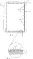
图1示出了多媒体电子设备,其包括设置有两个半壳体2和3的外壳,两个半壳体2和3被布置为通过它们的配合面4进行装配和固定,以限定容纳设备的功能元件的内部容积5。为了说明的清晰性,除了屏幕6以外,未示出设备1的功能部件。Figure 1 shows a multimedia electronic device comprising a housing provided with two half-
在下面的公开中还提到“前部2”和“后部3”,其参照半壳体还对应于设备的上面和下面。In the following disclosure there is also reference to "front 2" and "rear 3", which also correspond to the upper and lower sides of the device with reference to the half-shells.
根据本发明的实质方面,前部2和/或后部3中的至少一个包含了由第一材料生产的至少一个相应插入件7、8,该插入件通过包覆成型整合到由不同于第一材料的第二材料生产的相应框架9、10中。According to an essential aspect of the invention, at least one of the front part 2 and/or the
在接下来的描述中,所描述的实施方式使用由金属板生产的插入件和由塑性材料生产的框架。更宽泛地且仍在本发明范围内,插入件可由钢、或具有高熔点(例如,钢的熔点)的任意其它金属或金属合金生产。第二材料是有机材料,或者也可以是具有比第一材料的熔点低的金属或金属合金,例如,镁类金属或锌基压铸合金类合金的熔点。本发明的实质方面包括在低于插入件熔点的温度下将第二材料注入模具中。In the description that follows, the described embodiments use an insert produced from sheet metal and a frame produced from plastic material. More broadly, and still within the scope of the present invention, the insert may be produced from steel, or any other metal or metal alloy having a high melting point, such as that of steel. The second material is an organic material, or may also be a metal or a metal alloy having a melting point lower than that of the first material, for example, a melting point of a magnesium-based metal or a zinc-based die-casting alloy-based alloy. An essential aspect of the invention involves injecting the second material into the mold at a temperature below the melting point of the insert.
在图1所示的实施例中,前部2和后部3均包括整合到其各自的框架9、10内的插入件7、8。前部2的插入件7包括定出屏幕6的边界的中央窗11。后部3的插入件8是非中空的。在图4所示的、描述设备后部3的实施例中,插入件8具有对后部3下面的外表面主要部分进行覆盖的矩形。注意到,插入件形成设备外皮的一部分,并因此具有根据期望的外观和感觉功能而设计的外观和光泽(装饰、题字、哑光金属外观等)。In the embodiment shown in FIG. 1 , both the front part 2 and the
在它们位于设备外侧的接合区域中,插入件7、8和框架9、10具有相切的表面,以具有在插入件7、8和相应框架9、10之间完全平齐的连续外表面。因此,在设备1(图1)的上面和下面上的插入件7、8和框架9、10之间完全共面。In their junction areas outside the device, the
插入件由厚度小于0.5mm(例如,从0.1mm到0.5mm)的板状元件生产。这种大小的厚度能够使金属的材料成本最小。实际上,像这种薄的板状材料不必提供受欢迎的坚固特性。将外壳-屏幕系统构成为一个整体,是通过完美的平坦性提供了刚性和耐用性。粘合在板框架下面的外周处的屏幕模块提供了必要的刚性。因此所构成的外壳-屏幕系统在其整体上提供了期望的机械特性,例如在现代汽车底盘的情况下,在将玻璃表面粘合到板上之后获得了必要的刚性。The insert is produced from a plate-like element with a thickness of less than 0.5 mm (eg from 0.1 mm to 0.5 mm). Thicknesses of this size can minimize the material cost of the metal. In fact, sheet-like materials as thin as this don't have to offer the welcome robust properties. Forming the shell-screen system as a whole provides rigidity and durability through perfect flatness. A screen module glued at the periphery under the panel frame provides the necessary rigidity. The shell-screen system thus constituted provides in its entirety the desired mechanical properties, eg in the case of modern automobile chassis, the necessary rigidity is obtained after gluing the glass surface to the panel.
参照图3,注意到,每个插入件7、8包含边缘12,边缘12被折叠为与平坦中央区域13成近似90°角。通过少量材料对注入的金属-塑料合成外壳的尺寸特性进行控制的复杂性在于,施加到塑性材料的应力自然使金属板变形。为了减少收缩现象的影响,有必要为金属部件建立硬化能力。该硬化能力有利地由这些形成角度的边缘12提供。该方案尤其有利于仅占用非常少的外壳内部容积,该外壳因此几乎完全用于包含设备的功能元件(电子元件、蓄电池等)。因而本发明最大可能地使用外壳的内部容积。Referring to FIG. 3 , note that each
本发明提供了通过在包覆成型的过程中环绕/穿过/互连金属部件,从而增加插入件7、8与其框架9之间的附着点的数量。这能够最终防止塑料部件相对于金属部件的相对移动的可能性,并且增强了不同种类材料的装配的内聚性。如图3可见,提供了包覆成型的金属插入件8内的多个穿孔14,多个穿孔14优选地位于形成角度的边缘12内。确定穿孔的分布及其结合的开口表面,以避免可见缩痕的外观,该缩痕位于具有审美作用的外表面上的板内冲孔水平上。在包覆成型区域中,优选地,增加具有小结合表面的穿孔的数量,并且将它们均匀地分布在例如如图3所示的交错行中,以增强装配的内聚性。然而,必要的是,穿孔具有最小的结合表面,以使塑性材料很好地穿过这些开口。具有小结合表面的一些穿孔的均匀分布还提供了不减弱金属部件强度的优点。穿孔的最小结合表面取决于塑性材料的特性及其实现条件,例如,注入压力、材料温度、模具温度等。在本发明的实施方式中,结合的开口表面近似等于其直径在0.5mm到3mm之间的孔的表面。例如1mm数量级的直径是适当的。在不超出本发明范围的前提下,穿孔可具有任意形状,或者甚至仅包括简单的穿透孔。The present invention provides for increasing the number of attachment points between the
在实施方式变体中,穿孔可被凹口取代或补充。而且,如图3所示可看见几行穿孔,然而在变体中,还可提供单行穿孔。In an embodiment variant, the perforations can be replaced or supplemented by recesses. Also, several rows of perforations are visible as shown in FIG. 3 , however, in a variant, a single row of perforations may also be provided.
参照图2和5,还规定从边缘的外侧朝向外壳的内部容积5实现使塑性材料穿过穿孔,该穿过操作包括使塑性材料溢出到内部容积的尺寸d1小于边缘12外侧的塑性材料的厚度d2。尺寸d1和d2被认为垂直于边缘12的平面,而且示例性地,d1在0.2mm到0.5mm之间,d2在0.6mm到1.3mm之间。这些值的实例纯粹是为了说明具有相对小尺寸的产品(例如,便携式多媒体设备)。对于具有较大尺寸的产品,可在不超出本发明范围的前提下增大这些尺寸。With reference to Figures 2 and 5, it is also provided that from the outside of the edge towards the
不管分别用于插入件和框架的第一材料和第二材料,多个穿孔和凹口被布置和校准,以保证第二材料的注入完全穿过它们,从而产生有效的锚固和元件之间的交接区域的完美集成。Regardless of the first and second materials used for the insert and frame respectively, the plurality of perforations and notches are arranged and calibrated to ensure that the injection of the second material passes completely through them, thereby creating effective anchoring and inter-element bonding. Perfect integration in the handover area.
而且,通过例如螺钉和/或夹子的紧固装置提供前部2和后部3的装配和固定。例如,当这些紧固装置可被拧入紧固体或者还被拧入在由塑性材料生产的构件的一部分的足够厚部分内形成的孔内时,可使用螺钉固件。如果通过螺钉或者仅基于夹子将部件完全紧固在一起,那么没有超出本发明的范围。Furthermore, fitting and fixing of the front part 2 and the
夹子尤其有利的是它们能够在不产生过度费用的情况下增加数量。固定点数量的增加对于增强装配的刚性以及前部2和后部3(图1)之间的配合面4的平直度是有用的。在尤其有利的实施方式中,如图1和6所示,紧固件是基于将包含夹装配到由不同材料生产的容纳夹上。换句话说,通过夹紧使源自半壳体中的一个3的塑性框架10的凸耳15与源自另一半壳体2的插入件7的金属舌状物16(舌状物形成边缘的延伸部)协作,金属舌状物16包含开窗17,开窗17容纳凸耳15的凸出边缘。该实施例基于如下事实,即相对简单地模制由塑性材料制成的容积构件以及相对简单地在板中切割窗口。与将金属夹在金属上的方案相比,其优点是更好地控制尺寸链。比将塑料夹在塑料上的方案具有更好的可靠性和更少的干扰。Clips are particularly advantageous in that they allow for increased quantities without incurring undue expense. The increased number of fixing points is useful to increase the rigidity of the assembly and the straightness of the mating face 4 between the front part 2 and the rear part 3 (Fig. 1). In a particularly advantageous embodiment, as shown in FIGS. 1 and 6 , the fastener is based on fitting a containing clip to a receiving clip produced from a different material. In other words, the
在又一有利的实施方式中,面向其所抵靠的板状舌状物的切口18的边缘,塑性凸耳具有在由夹紧方案的两个部件中的一个和/或另一个的弹性引起的回复力作用下倾斜的表面,从而施加近似垂直的力,以保持配合面相接触。本发明的改进能够在制造的过程中或之后补偿构件的可能尺寸变化。在又一更优选实施方式中,如图7所示,提供了分阶段生产凸耳15′的倾斜表面19。另一构件的切口18的厚度中的每个阶梯的支撑表面平行于由夹紧方案的两个部件中的一个和/或另一个的弹性产生的力的方向。在装配这些构件的过程中,将压力施加到构件上,直到配合面在所有点上接触。当施加这个压力的时候,每个夹子会与相应的窗口接合,并且停靠在适当的台阶上,以在终止施加装配所需的力之后保持接合的装配。In yet another advantageous embodiment, facing the edge of the cutout 18 of the plate tongue against which it abuts, the plastic lug has a The restoring force acts on the inclined surface, thereby exerting an approximately vertical force to keep the mating surfaces in contact. The improvement of the invention makes it possible to compensate for possible dimensional variations of the components during or after manufacture. In yet another more preferred embodiment, as shown in Figure 7, an inclined surface 19 is provided for the staged production of lugs 15'. The bearing surface of each step in the thickness of the cutout 18 of the other member is parallel to the direction of the force generated by the elasticity of one and/or the other of the two parts of the clamping solution. During the assembly of these components, pressure is applied to the components until the mating surfaces touch at all points. When this pressure is applied, each clip engages the corresponding window and rests on the appropriate step to maintain the engaged assembly after termination of application of the force required for assembly.
在本发明未描述的实施方式变体中,第一部件和第二部件可被非直接而是通过一个或多个中间件装配和固定在一起。在这种情况下,紧固凸耳可以是这些中间件之一。In an embodiment variant not described in the invention, the first part and the second part can be fitted and fixed together not directly but via one or more intermediate pieces. In this case, the fastening lug can be one of these intermediate pieces.
有利地,可增加止动件和/或内肋20,以防止半壳体2、3的通常邻接且形成平角的边缘在紧固装置(图4)过紧的情况下打开或形成不平的角。这些肋20在装配半壳体9、10的过程中构成确定中心和/或标定的装置。这些肋构成越过半壳体9、10中的一个的塑性材料的配合面4的延伸部,并且至少部分地伸入另一半壳体9-10中。相对于插入件7、8,这些肋20位于壳体的内部容积5的侧部,并且具有作为底板的塑性材料,该塑性材料通过穿孔14或凹口凸出。因而插入件7、8局部地嵌入塑性材料中。Advantageously, stops and/or
规定半壳体之间的配合表面不一定要连续和/或共面。因此,一些实现变体提供了不连续的配合面,以给按钮和/或指示灯设置通道。It is specified that the mating surfaces between the half shells need not be continuous and/or coplanar. Therefore, some implementation variants provide discontinuous mating surfaces in order to provide passage for buttons and/or indicator lights.
可规定肋20沿着插入件的边缘12是连续的。然而,如图4所示,优选的实施方式包括提供塑性材料的周期性中断21,让金属插入件8局部暴露,以减小使金属变形的应力。It may be provided that the
规定了根据本发明的外壳包括直接与外壳相关的附加功能元件。It is provided that the housing according to the invention comprises additional functional elements directly associated with the housing.
-至少一个天线元件(金属子配件、印刷电路板等),这种类型的元件与根据本发明的外壳直接相关之处在于,至少一个天线元件的定位和/或特性考虑到由外壳的金属部件构成的地球平面和/或由塑性材料制成的部分中的元件的固定点;- at least one antenna element (metallic subassembly, printed circuit board, etc.), this type of element is directly related to the housing according to the invention in that the positioning and/or characteristics of the at least one antenna element take into account the metal parts of the housing Constituent earth planes and/or fixing points of elements in parts made of plastic material;
-光导器,用于传送光源发出的光,光源例如是定位在点处的LED,其优点在于技术和/或经济方面;定位在朝向转回点的印刷电路板上,其优点在于生物工程学和/或美学;定位在壳体上等等。- A light guide for transmitting the light emitted by a light source such as an LED positioned at a point, the advantage of which is technical and/or economical; a positioning on the printed circuit board towards the point of return, the advantage of which is bioengineering and/or aesthetics; positioning on the housing, etc.
在本发明尤其有利的实现变体中,这些功能元件可在模制过程中,以该方法的附加步骤的形式并入外壳中。In a particularly advantageous implementation variant of the invention, these functional elements can be incorporated into the housing as an additional step of the method during the molding process.
本发明还规定了考虑或成功使用插入件7、8的特定振动特性。The invention also provides for the specific vibration characteristics of the
事实上,根据本发明的外壳具有相对大表面积的背面,该背面由具有小厚度的板生产,从而不可避免地振动。因而,在本发明的第一实现变体规定了粘贴例如由弹性体或任意其它适当材料制成的阻尼衬垫22,处在设备1的固体内部部件23上(图8)。衬垫22可通过粘合泡沫或低粘合力胶粘剂被结合,以允许后续的拆卸。所述阻尼材料被布置为在背面的表面的至少一个点和固体内部部件23的表面处建立机械结合,固体内部部件23例如为蓄电池或硬盘类型的大存储容量子配件,从而当扬声器在壳体内部实现以再生声音数据时,防止不想要的背面干扰振动的开始。如果固体内部部件与背面的至少一个点之间不存在机械结合,那么在低频的再生过程中或者与外壳振动模式对应的特定频率的再生过程中,可能发生干扰的振动。添加适当的材料以在内部部件与背面之间建立连续性,并在适当的位置允许更好地排出热量和提高刚性,这产生用户拿来与质量相关的实心感觉。In fact, the housing according to the invention has a relatively large surface area back, produced from a plate of small thickness, so that vibrations are inevitable. Thus, in a first implementation variant of the invention it is provided to glue a damping
在本发明与声学相关的第二实现变体(图9)中,规定了根据本发明的外壳的背面用作隔膜,以再生声学数据。考虑到其薄度和表面,根据本发明的外壳的金属背面能够潜在地用作为电声换能器的隔膜。在根据本发明的外壳的背面的这种用途中,规定了在自由振动中产生电声换能器。为此,例如,规定了,将装配有用于形成板振动的适当电极的压电材料24结合至背面。压电方案的优点是其厚度小和不存在磁场,磁场可能造成与硬盘类型的文件存储器相近的问题。所提供的另一实施方式包括不再处于自由振动中,而是相对于固定的内部参照处于受控运动。在压电致动器的情况下,两个变体之间的不同之处可在于,将致动器的背部固定到固体部件23上的支撑件的至少一个点上,或者将其刚性地连接至外壳的其它刚性部分。当然,可在不超出本发明范围的前提下使用任何其它类型的致动器,例如,基于磁的致动器。本发明还提供了适当的信号处理,以提高感知到的声音质量。实际上,外壳背面的板8主要不是被设计为扬声器隔膜。响应曲线可能是强烈非线性的,振动的具体模式会产生不令人满意的声音质量。本发明所提出的这个问题的解决方案是,通过数字装置来处理信号,数字装置例如是通常在现代电子设备中实现且对以数字形式存储或接收的信号进行解码的数字信号处理器(DSP)。附加处理的参数专用于根据本发明的外壳模型,以补偿通过外壳背面重现的缺点。在具有麦克风的某些设备中,建议用户进行可选的组合线性处理,以完善重现质量。In a second acoustically related implementation variant of the invention ( FIG. 9 ), provision is made for the rear side of the housing according to the invention to be used as a diaphragm for reproducing acoustic data. Considering its thinness and surface, the metal back of the housing according to the invention can potentially be used as a diaphragm for an electro-acoustic transducer. In this use of the rear side of the housing according to the invention provision is made for the generation of electroacoustic transducers in free vibrations. For this purpose, for example, provision is made to bond to the back a
本发明的实现对减小计算机外壳的厚度尤其有效。在具有如图13所示的折叠屏幕的便携式计算机中,与均用于屏幕部分和用于包含键盘的底部的现有技术状态相比,本发明允许显著地节省厚度。根据本发明的金属插入件30的可视部分定出屏幕、键盘和触摸板的边界。该图还图示了与连续平面31不在一条线上的两个半壳体之间的配合面的实施例。Implementation of the present invention is particularly effective for reducing the thickness of computer housings. In a portable computer with a folding screen as shown in Figure 13, the invention allows a significant savings in thickness compared to the state of the art both for the screen part and for the bottom containing the keyboard. The visible part of the
图14图示了设备框架内的本发明实现,该设备具有“写字板”类型的形状因素。这些可以是所有类型和所有屏幕尺寸的设备,例如从用于便携式设备的几个对角英寸到“平板”电视设备情况下的40英寸。该图还图示了用于容易地定位按钮、连接器、报警灯32或需要与外部交互的所有其它装置的配合面中的不连续性的实施例。如果适当,这些可以是通风入口。Figure 14 illustrates an implementation of the invention within the framework of a device having a "tablet" type form factor. These can be devices of all types and screen sizes, for example from a few diagonal inches for portable devices to 40 inches in the case of "flat" TV devices. The figure also illustrates an embodiment of a discontinuity in the mating surface for easy positioning of buttons, connectors, warning lights 32 or any other device that requires interaction with the outside. These may be ventilation inlets, if appropriate.
制造根据本发明的电子设备的外壳的方法是基于在模具26中使用浮动模芯27。浮动模芯是指形成模具一部分的移动件,其主要功能是通过必要的力将金属插入件7钉在模具26底部处的支撑表面上,从而使该插入件7在塑形材料的注入和冷却周期内保持其位置。浮动模芯27可与模具的一部分成一体并且被引导为在沿着箭头F3施加金属件7的保持力的方向平移。这种保持力可通过一个或多个弹簧产生,弹簧抵靠在模具的、与浮动模芯成为一体的那部分上并且受益于所施加的力以关闭模具。该保持力还可通过一个或多个汽缸产生,汽缸尤其与浮动模芯的驱动相关联。The method of manufacturing the housing of an electronic device according to the invention is based on the use of floating
根据本发明的方法的步骤如下:The steps according to the method of the present invention are as follows:
-获得金属插入件7、8,尤其通过包含切割、牵拉、冲压、折叠等步骤的方法生产金属插入件7、8;- Obtaining metal inserts 7, 8, in particular producing
-将插入件7、8定位在打开的模具26中;- positioning of the
-使用浮动模芯27,以在插入件7、8上施加约束力,从而保持将插入件7、8压在模具26的支撑表面上;- use of floating
-关闭模具26;- close the
-将塑性材料注入模具26。- Injecting plastic material into the
当然,在冷却阶段之后、注入结束时,提供了射出完成件的后续步骤。Of course, after the cooling phase, at the end of the injection, a subsequent step of injection of the finished part is provided.
在厚度在0.1mm到0.5mm之间的金属箔或金属板内获得金属插入件。金属件可通过任何方法或者可包括例如切割、牵拉、冲压、折叠等步骤的方法的任意组合而生产。Metal inserts are obtained in metal foils or metal plates with a thickness between 0.1 mm and 0.5 mm. The metal piece may be produced by any method or any combination of methods that may include steps such as cutting, drawing, stamping, folding, and the like.
根据模芯27(图11)的第一实施方式变体,其设置在金属插入件7内,在与插入件7的平坦中央区域成近似90°角的、金属插入件7的边缘之间,模芯27在其边缘包括槽口28,槽口28在与插入件7的凸出部对应的槽口中限定了塑性材料。插入件7的边缘12在这种情况下是直的。根据另一实施方式变体(图12),模芯27′设置在金属插入件7′内,在形成近似90°角的插入件7′的边缘和槽口29的外轮廓之间,还在与插入件7′的凸出部对应的槽口内限定了塑性材料。浮动模芯27′在这种情况下具有直的边缘。According to a first embodiment variant of the core 27 ( FIG. 11 ), which is arranged inside the
注意到,因而能够:Note that it is thus possible to:
-在构件的可视边缘上具有厚度不变的塑料;- plastic with a constant thickness on the visible edges of the member;
-因缩回而减小了变形应力,在未示出的内壁上的塑性材料的连续性上产生周期性的断裂以减小应力(由于塑性材料冷却过程中的收缩);- reduction of deformation stresses due to retraction, periodic breaks in the continuity of the plastic material on the inner wall not shown to reduce stress (due to shrinkage of the plastic material during cooling);
-不管内侧的小厚度而将塑料保持在内壁上,以获得良好的“铆接”现象,这是需要用来获得材料之间的持久内聚性的。- Keeping the plastic on the inner wall despite the small thickness of the inner side to obtain a good "riveting" phenomenon, which is required to obtain a permanent cohesion between the materials.
对于实际的塑料注入,设备的温度例如在90℃的量级。其周期比模制不由塑性材料制成的构件的情况中的周期要长,这是因为根据本发明的方法需要:For the actual plastic injection, the temperature of the device is for example of the order of 90°C. The cycle time is longer than in the case of molding components not made of plastic material, because the method according to the invention requires:
-用于加热金属件的时间。因而能够形成良好的塑料-金属粘合并且能够获得不易破裂的塑料;- the time used to heat the metal piece. Thus a good plastic-metal bond can be formed and a plastic that is not easily broken can be obtained;
-在冷却过程中保持在压力下,以防止收缩。-Keep under pressure during cooling to prevent shrinkage.
模制参数(例如,不同的温度)和周期是折衷的结果并且具体根据塑性材料的特性而适用。通过相对于非限制性实施例方式给出的值修改任何具体参数,未超出本发明的范围。Molding parameters (eg, different temperatures) and cycles are a result of compromises and are adapted in particular according to the properties of the plastic material. It is not outside the scope of the invention by modifying any specific parameter relative to the values given by way of non-limiting examples.
该方法的进一步细节如下:Further details of the method are as follows:
-流体材料能够生产薄的壁并且能够进入表面积小的开口(穿孔、凹口),开口布置在将被包覆成型的插入件内,以获得不同类型材料的优良内聚性;- The fluid material enables the production of thin walls and access to openings (perforations, notches) of small surface area, which are arranged in the insert to be overmolded, in order to obtain a good cohesion of the different types of materials;
-浮动模芯能够保持压在设备上的板,并且防止材料在压力的作用下在板下通过。因而能够获得不同类型的表面的连续性,而没有焊瘤并且分割线在视觉上完美而不需要后续返工;- The floating mandrel is able to hold the plate pressed against the equipment and prevent the material from passing under the plate under pressure. Continuity of different types of surfaces can thus be obtained without weld flashes and visually perfect dividing lines without subsequent rework;
-由薄板制成的插入件的厚度小于0.5mm;- the thickness of inserts made of thin plates is less than 0.5 mm;
-穿孔或凹口分布在板的整个表面区域上,以具有良好的金属/塑料附着性。孔的直径为0.5mm到1.2mm的量级,例如1mm的量级,以避免在塑性材料中形成缩痕,缩痕尤其在为由塑性材料制成的部件选择镜面抛光时看得见。- Perforations or notches are distributed over the entire surface area of the plate for good metal/plastic adhesion. The diameter of the holes is of the order of 0.5 mm to 1.2 mm, for example of the order of 1 mm, in order to avoid the formation of sink marks in the plastic material, which are especially visible when a mirror finish is chosen for parts made of plastic material.
当然,如果取代能够在每个周期内生产根据本发明的一个壳体的模具,使用具有多个腔和浮动模芯的模具,从而在每个周期内生产根据本发明的多个壳体,那么这是未超出本发明范围的。Of course, if instead of a mold capable of producing one shell according to the invention per cycle, a mold with multiple cavities and floating cores is used to produce multiple shells according to the invention per cycle, then This is not beyond the scope of the present invention.
注意,根据本发明的电子设备在不超出本发明范围的前提下可以是多种类型,这是由于设备包括至少单个壳体或包括铰接至另一壳体的壳体,这些壳体中的一个包括至少一个前部或后部,前部或后部设置有根据先前描述的特性和修改、通过包覆成型的金属插入件。本发明的电子设备的非限制性实施例为:Note that the electronic device according to the invention may be of various types without exceeding the scope of the invention, since the device comprises at least a single housing or a housing hinged to another housing, one of these housings Comprising at least one front or rear part provided with a metal insert by overmolding according to the characteristics and modifications previously described. Non-limiting examples of electronic devices of the present invention are:
-单片翻盖或滑盖手机;- Monolithic flip or slider phones;
-多媒体播放器/录音机(单片的或具有可移动的部件);- multimedia players/recorders (monolithic or with removable parts);
-具有折叠屏幕的便携式计算机;- Laptop computers with folding screens;
-“写字板”类型的计算机;- Computers of the "WordPad" type;
-外部计算机屏幕;- external computer screen;
-电视机。-TV set.
根据设备的类型,能够例如仅具有前部或后部,即,由包覆成型的金属插入件构成的单面。作为一个变体,相同设备能够具有两面,每个面设置有包覆成型的金属插入件。作为一个变体,在设备包括几个可相互移动的部件(具有折叠屏幕的计算机或可根据相同原理使用的其它设备)的情况下,设备能够具有一个、两个、三个或四个面,每个面均设置有包覆成型的金属插入件。Depending on the type of device, it is possible, for example, to have only the front or the rear, ie a single side consisting of an overmoulded metal insert. As a variant, the same device can have two sides each provided with an overmolded metal insert. As a variant, the device can have one, two, three or four sides, in the case of a device comprising several mutually movable parts (a computer with a folding screen or other devices that can be used according to the same principle), Each face is provided with an overmolded metal insert.
而且,在先前的描述中,描述了包括第一插入件7和第二插入件8的设备,第一插入件7设置有用于屏幕的中央窗,第二插入件8形成设备的背面。不论单个设备上的插入件的形状或尺寸的组合,本发明均以相同的方式应用。插入件能够非常均匀地设置在屏幕、键盘(触摸或非触摸)、“写字板”类型的控制设备等的周围。Also, in the previous description, a device was described comprising a
当然,本发明不限于刚才描述的实施例,在不超出本发明范围的前提下,可对其添加多个改进,可进行特性和/或实现的组合的其它选择。而且,所提到的示例性方案或技术标准是提交本专利申请时的方案或技术标准。它们可能消失或由不一定使本发明自身废弃的其它方案或技术标准所取代。Of course, the present invention is not limited to the embodiments just described, and many improvements can be added thereto, and other combinations of characteristics and/or implementations can be selected without going beyond the scope of the present invention. Moreover, the mentioned exemplary scheme or technical standard is the scheme or technical standard at the time of filing this patent application. They may disappear or be replaced by other solutions or technical standards which do not necessarily render the invention itself obsolete.
例如,尽管使用厚度小于0.5mm的金属板在生产根据本发明、适用于小型设备的外壳的方法的实现的框架内是优选的,但是生产根据本发明、用于包含大尺寸屏幕(例如,电视机或计算机屏幕)的设备的外壳可能需要厚度大于0.5mm的板。这尤其对于具有大质量封装屏幕面板是真实的。在这种情况下,厚度在0.5mm到2mm之间的板是适当的。For example, although the use of metal sheets with a thickness of less than 0.5 mm is preferred within the framework of the implementation of the method for producing housings suitable for small devices according to the invention, the production of housings according to the invention for containing large-sized screens (for example, televisions) PCs or computer screens) may require boards with a thickness greater than 0.5mm for housings. This is especially true for encapsulating screen panels with high mass. In this case, a plate with a thickness between 0.5mm and 2mm is suitable.
Claims (17)
Applications Claiming Priority (2)
| Application Number | Priority Date | Filing Date | Title |
|---|---|---|---|
| WOPCT/FR2009/050773 | 2009-04-27 | ||
| PCT/FR2009/050773WO2010125250A1 (en) | 2009-04-27 | 2009-04-27 | Housing for electronic apparatus, apparatus including such housing and method for making such housing |
Publications (2)
| Publication Number | Publication Date |
|---|---|
| CN101877951Atrue CN101877951A (en) | 2010-11-03 |
| CN101877951B CN101877951B (en) | 2012-09-05 |
Family
ID=41429251
Family Applications (1)
| Application Number | Title | Priority Date | Filing Date |
|---|---|---|---|
| CN201010174636XAExpired - Fee RelatedCN101877951B (en) | 2009-04-27 | 2010-04-27 | Housing for an electronic device, device comprising such a housing and method for manufacturing such a housing |
Country Status (6)
| Country | Link |
|---|---|
| US (1) | US8338703B2 (en) |
| CN (1) | CN101877951B (en) |
| DE (1) | DE112009004704T5 (en) |
| FR (1) | FR2944944A1 (en) |
| GB (1) | GB2481928B (en) |
| WO (1) | WO2010125250A1 (en) |
Cited By (15)
| Publication number | Priority date | Publication date | Assignee | Title |
|---|---|---|---|---|
| CN102049838A (en)* | 2010-11-09 | 2011-05-11 | 深圳庆和胶粘制品有限公司 | Method for molding metal piece with view window and plastic molding product and application thereof |
| CN102189385A (en)* | 2011-05-19 | 2011-09-21 | 戴护民 | Composite manufacturing process for handy terminal exterior piece, and product thereof |
| CN102711003A (en)* | 2012-01-05 | 2012-10-03 | 瑞声声学科技(深圳)有限公司 | Loudspeaker, loudspeaker casing and manufacturing method of loudspeaker casing |
| CN103677088A (en)* | 2012-09-05 | 2014-03-26 | 上海优爱宝机器人技术有限公司 | Stacked tablet computer and processing method thereof |
| CN103874348A (en)* | 2012-12-10 | 2014-06-18 | 群光电能科技股份有限公司 | Manufacturing method and structure of power supply case group |
| CN105935896A (en)* | 2015-03-06 | 2016-09-14 | 苹果公司 | Co-finishing surfaces |
| CN107946505A (en)* | 2016-10-13 | 2018-04-20 | 罗伯特·博世有限公司 | Battery module housings |
| US10071539B2 (en) | 2014-09-30 | 2018-09-11 | Apple Inc. | Co-sintered ceramic for electronic devices |
| US10216233B2 (en) | 2015-09-02 | 2019-02-26 | Apple Inc. | Forming features in a ceramic component for an electronic device |
| US10335979B2 (en) | 2014-09-30 | 2019-07-02 | Apple Inc. | Machining features in a ceramic component for use in an electronic device |
| CN110641381A (en)* | 2018-06-27 | 2020-01-03 | 佛吉亚汽车内部设备工业公司 | Screen-equipped internal structure of vehicle and manufacturing method for manufacturing the same |
| US10542628B2 (en) | 2017-08-02 | 2020-01-21 | Apple Inc. | Enclosure for an electronic device having a shell and internal chassis |
| CN111068183A (en)* | 2019-12-31 | 2020-04-28 | 青岛温可微电子科技有限公司 | Manufacturing method of welding type heating device |
| CN113419600A (en)* | 2019-03-11 | 2021-09-21 | 三星电子株式会社 | Electronic device including foldable conductive plate |
| TWI772268B (en)* | 2015-08-31 | 2022-08-01 | 新加坡商統合實業有限公司 | Ir-compatible display frame for an ir-touch electronic device |
Families Citing this family (26)
| Publication number | Priority date | Publication date | Assignee | Title |
|---|---|---|---|---|
| TWI418281B (en)* | 2010-09-15 | 2013-12-01 | Quanta Comp Inc | Method for manufacturing shell of electronic device |
| FR2980906B1 (en)* | 2011-09-29 | 2013-10-11 | Archos | RIGID FINE LITTER HOUSING FOR ELECTRONIC APPARATUS |
| US20130098788A1 (en)* | 2011-10-19 | 2013-04-25 | Patrick McCarville | Cell Phone Case |
| FR2981814B1 (en)* | 2011-10-21 | 2013-12-27 | Continental Automotive France | RADIOFREQUENCY TRANSMITTER WITH HETEROGENEUS METAL / PLASTIC STRUCTURE |
| US8849437B2 (en)* | 2012-09-25 | 2014-09-30 | Apple Inc. | Adaptive machining for improving assembly fit of consumer electronics |
| US9555597B2 (en)* | 2012-12-27 | 2017-01-31 | Intel Corporation | Foam core chassis |
| FR3003963B1 (en)* | 2013-03-29 | 2016-12-30 | Dav | INTERFACE MODULE |
| US9616603B2 (en) | 2013-05-06 | 2017-04-11 | Google Technology Holdings LLC | Floating core for glass insert molding method and apparatuses therefrom |
| US9586351B2 (en)* | 2013-05-06 | 2017-03-07 | Google Technology Holdings LLC | Floating core for glass insert molding method and apparatuses therefrom |
| CN203423220U (en)* | 2013-06-17 | 2014-02-05 | 中兴通讯股份有限公司 | Battery casing assembly for electronic equipment, plastic metal assembly and plastic part |
| CN103335205B (en)* | 2013-06-26 | 2015-12-02 | 天津博信汽车零部件有限公司 | A kind of hydraulic press intelligent Safeguard |
| WO2014209410A1 (en)* | 2013-06-29 | 2014-12-31 | Intel Corporation | Enabling stiff plastic chassis with thin metal skins |
| JP6193743B2 (en)* | 2013-11-25 | 2017-09-06 | 京セラ株式会社 | Mobile device |
| JP6264905B2 (en)* | 2014-01-31 | 2018-01-24 | 住友電気工業株式会社 | Composite member and method of manufacturing composite member |
| WO2016014047A1 (en) | 2014-07-23 | 2016-01-28 | Apple Inc. | Adaptive processes for improving integrity of surfaces |
| US10649497B2 (en)* | 2014-07-23 | 2020-05-12 | Apple Inc. | Adaptive processes for improving integrity of surfaces |
| US9529389B1 (en)* | 2014-09-25 | 2016-12-27 | Amazon Technologies, Inc. | Variable plated device enclosure |
| CN205680039U (en) | 2015-05-20 | 2016-11-09 | 苹果公司 | Electronic device |
| GB201511715D0 (en)* | 2015-07-03 | 2015-08-19 | Aquaterra Ltd | Detachable multi-function rim for a portable electronic device |
| US10129375B1 (en) | 2017-05-11 | 2018-11-13 | Microsoft Technology Licensing, Llc | Thin section interlock geometry for molding plastic |
| CN107900619B (en)* | 2017-11-20 | 2020-02-28 | 珠海市魅族科技有限公司 | Terminal surface cover frame and manufacturing method thereof, and mold and manufacturing method thereof |
| CN109568968A (en)* | 2018-10-31 | 2019-04-05 | 努比亚技术有限公司 | A kind of game terminal |
| CN110640970B (en)* | 2019-08-26 | 2022-07-15 | 广东长盈精密技术有限公司 | Method for processing functional hole of electronic product shell and insert adopted by same |
| WO2021164941A1 (en) | 2020-02-20 | 2021-08-26 | Eaton Intelligent Power Limited | Enclosure for light fixture |
| EP3898165B1 (en) | 2020-03-05 | 2022-10-12 | Google LLC | Zero or low-draft angle injection molding method and system |
| EP4329442A4 (en)* | 2021-06-03 | 2024-10-09 | Samsung Electronics Co., Ltd. | Electronic device comprising housing, and housing manufacturing method |
Citations (3)
| Publication number | Priority date | Publication date | Assignee | Title |
|---|---|---|---|---|
| DE4322753A1 (en)* | 1993-07-08 | 1995-01-12 | Philips Patentverwaltung | Housing for electrical telecommunications appliances |
| CN1303578A (en)* | 1998-07-07 | 2001-07-11 | Trw车辆电气与零件有限两合公司 | Housings for electronic units, especially air bag controllers |
| CN1328909A (en)* | 2000-06-19 | 2002-01-02 | 株式会社日立制作所 | Metal plate and resin mixed structure shell |
Family Cites Families (7)
| Publication number | Priority date | Publication date | Assignee | Title |
|---|---|---|---|---|
| US5339222A (en)* | 1993-04-06 | 1994-08-16 | The Whitaker Corporation | Shielded printed circuit card holder |
| EP0633585B1 (en) | 1993-07-08 | 1997-11-05 | Philips Patentverwaltung GmbH | Housing for electric communication apparatus |
| US7711400B2 (en) | 2000-12-29 | 2010-05-04 | Vertu Limited | Casing |
| US8989823B2 (en)* | 2005-08-25 | 2015-03-24 | Nec Corporation | Casing for portable device |
| US7518880B1 (en)* | 2006-02-08 | 2009-04-14 | Bi-Link | Shielding arrangement for electronic device |
| JP5147492B2 (en)* | 2008-03-28 | 2013-02-20 | 矢崎総業株式会社 | Electrical junction box storage box |
| CN101616560B (en)* | 2008-06-27 | 2012-05-23 | 深圳富泰宏精密工业有限公司 | Metal shell and manufacturing method thereof |
- 2009
- 2009-04-27GBGB1115008.3Apatent/GB2481928B/ennot_activeExpired - Fee Related
- 2009-04-27WOPCT/FR2009/050773patent/WO2010125250A1/enactiveApplication Filing
- 2009-04-27DEDE112009004704Tpatent/DE112009004704T5/ennot_activeWithdrawn
- 2010
- 2010-04-26FRFR1053165Apatent/FR2944944A1/enactivePending
- 2010-04-27CNCN201010174636XApatent/CN101877951B/ennot_activeExpired - Fee Related
- 2010-04-27USUS12/767,980patent/US8338703B2/ennot_activeExpired - Fee Related
Patent Citations (3)
| Publication number | Priority date | Publication date | Assignee | Title |
|---|---|---|---|---|
| DE4322753A1 (en)* | 1993-07-08 | 1995-01-12 | Philips Patentverwaltung | Housing for electrical telecommunications appliances |
| CN1303578A (en)* | 1998-07-07 | 2001-07-11 | Trw车辆电气与零件有限两合公司 | Housings for electronic units, especially air bag controllers |
| CN1328909A (en)* | 2000-06-19 | 2002-01-02 | 株式会社日立制作所 | Metal plate and resin mixed structure shell |
Cited By (20)
| Publication number | Priority date | Publication date | Assignee | Title |
|---|---|---|---|---|
| CN102049838A (en)* | 2010-11-09 | 2011-05-11 | 深圳庆和胶粘制品有限公司 | Method for molding metal piece with view window and plastic molding product and application thereof |
| CN102189385A (en)* | 2011-05-19 | 2011-09-21 | 戴护民 | Composite manufacturing process for handy terminal exterior piece, and product thereof |
| CN102189385B (en)* | 2011-05-19 | 2014-06-04 | 戴护民 | Composite manufacturing process for handy terminal exterior piece, and product thereof |
| CN102711003A (en)* | 2012-01-05 | 2012-10-03 | 瑞声声学科技(深圳)有限公司 | Loudspeaker, loudspeaker casing and manufacturing method of loudspeaker casing |
| CN102711003B (en)* | 2012-01-05 | 2015-11-11 | 瑞声声学科技(深圳)有限公司 | Loud speaker, loudspeaker housing and preparation method thereof |
| CN103677088A (en)* | 2012-09-05 | 2014-03-26 | 上海优爱宝机器人技术有限公司 | Stacked tablet computer and processing method thereof |
| CN103874348A (en)* | 2012-12-10 | 2014-06-18 | 群光电能科技股份有限公司 | Manufacturing method and structure of power supply case group |
| US10071539B2 (en) | 2014-09-30 | 2018-09-11 | Apple Inc. | Co-sintered ceramic for electronic devices |
| US10335979B2 (en) | 2014-09-30 | 2019-07-02 | Apple Inc. | Machining features in a ceramic component for use in an electronic device |
| US10207387B2 (en) | 2015-03-06 | 2019-02-19 | Apple Inc. | Co-finishing surfaces |
| CN105935896A (en)* | 2015-03-06 | 2016-09-14 | 苹果公司 | Co-finishing surfaces |
| TWI772268B (en)* | 2015-08-31 | 2022-08-01 | 新加坡商統合實業有限公司 | Ir-compatible display frame for an ir-touch electronic device |
| US10216233B2 (en) | 2015-09-02 | 2019-02-26 | Apple Inc. | Forming features in a ceramic component for an electronic device |
| CN107946505A (en)* | 2016-10-13 | 2018-04-20 | 罗伯特·博世有限公司 | Battery module housings |
| US10542628B2 (en) | 2017-08-02 | 2020-01-21 | Apple Inc. | Enclosure for an electronic device having a shell and internal chassis |
| CN110641381A (en)* | 2018-06-27 | 2020-01-03 | 佛吉亚汽车内部设备工业公司 | Screen-equipped internal structure of vehicle and manufacturing method for manufacturing the same |
| CN113419600A (en)* | 2019-03-11 | 2021-09-21 | 三星电子株式会社 | Electronic device including foldable conductive plate |
| CN113419600B (en)* | 2019-03-11 | 2022-03-11 | 三星电子株式会社 | Electronic devices including foldable conductive plates |
| US11300996B2 (en) | 2019-03-11 | 2022-04-12 | Samsung Electronics Co., Ltd. | Electronic device including foldable conductive plate |
| CN111068183A (en)* | 2019-12-31 | 2020-04-28 | 青岛温可微电子科技有限公司 | Manufacturing method of welding type heating device |
Also Published As
| Publication number | Publication date |
|---|---|
| US8338703B2 (en) | 2012-12-25 |
| US20100270052A1 (en) | 2010-10-28 |
| GB2481928B (en) | 2014-05-14 |
| GB2481928A (en) | 2012-01-11 |
| GB201115008D0 (en) | 2011-10-12 |
| CN101877951B (en) | 2012-09-05 |
| FR2944944A1 (en) | 2010-10-29 |
| WO2010125250A1 (en) | 2010-11-04 |
| DE112009004704T5 (en) | 2012-09-20 |
Similar Documents
| Publication | Publication Date | Title |
|---|---|---|
| CN101877951A (en) | Case for electronic device, device including same, and method for manufacturing same | |
| KR101242849B1 (en) | Portable computing system | |
| US9779894B2 (en) | Button features of an electronic device | |
| JP6482477B2 (en) | Device housing including transparent lens having stepped flange and method of manufacturing the same | |
| US9829930B2 (en) | Portable computer electrical grounding and audio system architectures | |
| KR101819734B1 (en) | Shutter covered on sound hole of loudspeaker module and assembling method thereof, loudspeaker module | |
| US20180192202A1 (en) | Miniature speaker | |
| KR20120040274A (en) | Methods for integrally trapping a glass insert in a metal bezel and produced electronic device | |
| US8333862B2 (en) | Self fixturing assembly techniques | |
| WO2016174834A1 (en) | Electronic device with built-in acoustic electronic component | |
| CN105376930A (en) | Electronic product casing and manufacturing method thereof | |
| CN101895710A (en) | Panel shell of television and preparation method thereof | |
| CN106303862B (en) | Module shell subassembly, speaker module and electronic equipment | |
| JP2006311324A (en) | Resin molded product and resin molding method | |
| KR101972156B1 (en) | Lcd frame, mobile terminal comprising it and manufacturing method thereof | |
| CN202488627U (en) | Loudspeaker shell and loudspeaker utilizing same | |
| WO2013045977A1 (en) | Apparatus and methods of forming molded parts | |
| CN112104935A (en) | Loudspeaker box | |
| CN109831554B (en) | Mainboard upper cover of electronic equipment, manufacturing method thereof and electronic equipment | |
| CN205408147U (en) | Speaker shell and speaker module | |
| JP2001007574A (en) | Electronics | |
| TWI498069B (en) | Housing for electronic device and method for making the same | |
| CN110351649B (en) | Loudspeaker box and assembling method thereof | |
| JP3177440B2 (en) | Mobile phone | |
| CN119729292A (en) | Electronic equipment |
Legal Events
| Date | Code | Title | Description |
|---|---|---|---|
| C06 | Publication | ||
| PB01 | Publication | ||
| C10 | Entry into substantive examination | ||
| SE01 | Entry into force of request for substantive examination | ||
| C14 | Grant of patent or utility model | ||
| GR01 | Patent grant | ||
| CF01 | Termination of patent right due to non-payment of annual fee | ||
| CF01 | Termination of patent right due to non-payment of annual fee | Granted publication date:20120905 Termination date:20200427 |