CN101876753B - Hybrid illumination system for head-up display - Google Patents
Hybrid illumination system for head-up displayDownload PDFInfo
- Publication number
- CN101876753B CN101876753BCN2010102015323ACN201010201532ACN101876753BCN 101876753 BCN101876753 BCN 101876753BCN 2010102015323 ACN2010102015323 ACN 2010102015323ACN 201010201532 ACN201010201532 ACN 201010201532ACN 101876753 BCN101876753 BCN 101876753B
- Authority
- CN
- China
- Prior art keywords
- light
- display
- unit
- head
- lighting system
- Prior art date
- Legal status (The legal status is an assumption and is not a legal conclusion. Google has not performed a legal analysis and makes no representation as to the accuracy of the status listed.)
- Expired - Fee Related
Links
Images


Landscapes
- Instrument Panels (AREA)
Abstract
Description
Translated fromChinese【技术领域】【Technical field】
本发明通常涉及平视显示器(head-up display),特别涉及平视显示器的照明系统。This invention relates generally to head-up displays, and more particularly to lighting systems for head-up displays.
【背景技术】【Background technique】
平视显示器(HUD)是将图像投影在一个可见表面上的系统,该可见表面所在的位置允许观察者始终保持一个姿势,显示器或仪表板的高度大致与观察者的眼睛成水平,让观察者始终保持平视的姿态,而不需要低头观看。平视显示器可用于各种环境如机动车辆、航空器、头盔和其它观察者不能分散其注视的重要情况。A head-up display (HUD) is a system that projects an image onto a visible surface in a position that allows the observer to maintain a posture at all times. Maintain an eye-level posture without looking down. Head-up displays can be used in a variety of environments such as motor vehicles, aircraft, helmets, and other critical situations where the observer cannot distract their gaze.
尽管平视显示器适用于这种环境,但有时在明亮环境光条件下辨别图像会很困难。因此,需要能够在高环境光条件下容易观看的显示器。在这之前,在收集平视显示器的环境光方面已经有许多努力。WO 95/13557是这种平视显示器的一个例子,其在显示器里使用一个环境光光源,其投影图象在挡风玻璃上。同样,在美国专利4,997,263和美国专利7,430,349里,也是聚合环境光和另一个光源。尽管都是使用环境光和另一个光源,前者有较低的环境光收集效率,而后者涉及复杂的收集光纤。此外,这两个专利聚合这两个光源,却都没有提供一个均匀光源用于显示。While the HUD is fine for this environment, it can sometimes be difficult to discern the image in bright ambient light conditions. Accordingly, there is a need for displays that can be easily viewed under high ambient light conditions. There have been many efforts to collect ambient light for HUDs before this. WO 95/13557 is an example of such a head-up display which uses an ambient light source in the display which projects an image on the windshield. Likewise, in US Patent 4,997,263 and US Patent 7,430,349, ambient light and another light source are aggregated. Although both use ambient light and another light source, the former has low ambient light collection efficiency, while the latter involves complex collection fibers. Furthermore, both patents aggregate the two light sources, but neither provides a uniform light source for display.
因此,需要改进平视显示器的光源,使得其既能够提供足够显示亮度又能提供一个均匀光源用于显示,以便能够允许在高环境光条件下清楚地观看。Therefore, there is a need for an improved light source for a head-up display that can provide both sufficient display brightness and a uniform light source for display to allow clear viewing in high ambient light conditions.
【发明概述】【Summary of Invention】
本发明是一个平视显示器(HUD),其利用来自外界的环境光和来自电光源的可视光用于照明被投影的图像。其包括集光单元、第一光束成形光学单元、第二光束成形光学单元、混光单元、聚光单元、偏振分束器(PBS)、反射显示器单元、投影单元、散光膜和一个光源。根据各个组件的位置,可以选择性地使用反射镜来改变光路经。此外,其还可以包括一个亮度增强器和一个预偏器(pre-polarizer)。The present invention is a heads-up display (HUD) that utilizes ambient light from the outside world and visible light from an electric light source for illuminating the projected image. It includes a light collecting unit, a first beam shaping optical unit, a second beam shaping optical unit, a light mixing unit, a light collecting unit, a polarizing beam splitter (PBS), a reflective display unit, a projection unit, a diffuser film and a light source. Depending on the position of the individual components, mirrors can optionally be used to alter the light path. In addition, it may also include a brightness enhancer and a pre-polarizer.
集光单元从外界收集环境光,并将其重新导向至集光单元的轴,使得其落在一个预定锥角(cone angle)内。在本发明第一实施例里,其中集光单元的轴和第一光束成形光学器件的轴平衡且重合,由集光单元整合的光被直接导入到第一光束成形光学单元内。在本发明第二实施例里,其中集光单元的轴和第一光束成形光学器件的轴不是平衡的,由集光单元整合的光通过一个反射单元被导入到光束成形光学单元内。第一光束成形光学单元的功能是准直收集的环境光,并通过一个反射镜将其导向混光单元。The light collecting unit collects ambient light from the outside and redirects it to the axis of the light collecting unit such that it falls within a predetermined cone angle. In the first embodiment of the present invention, wherein the axes of the light collecting unit and the first beam shaping optical device are balanced and coincident, the light integrated by the light collecting unit is directly guided into the first beam shaping optical unit. In the second embodiment of the present invention, wherein the axis of the light collecting unit and the axis of the first beam shaping optics are not balanced, the light integrated by the light collecting unit is guided into the beam shaping optical unit through a reflective unit. The function of the first beam shaping optical unit is to collimate the collected ambient light and direct it to the light mixing unit through a mirror.
来自光源的可视光穿过光束成形光学单元用于准直。随后,光束成形光学单元的准直光通过一个反射镜被导向混光单元。Visible light from the light source is passed through the beam shaping optics for collimation. Subsequently, the collimated light from the beam shaping optics is directed to the light mixing unit via a mirror.
混光单元混合并均匀化混光单元内的所有光,并控制将被投影到反射显示器单元上的混光的散射角,使得反射显示器单元接收到均匀照明。接着,从混光单元出来的混合光被导入到聚光单元,然后其将光导向PBS。The light mixing unit mixes and homogenizes all the light within the light mixing unit, and controls the scattering angle of the mixed light to be projected onto the reflective display unit, so that the reflective display unit receives uniform illumination. Next, the mixed light from the light mixing unit is introduced into the light concentrating unit, which then directs the light to the PBS.
若包含一个预偏器,其安装的最佳位置应在聚光单元和PBS之间。预偏器的朝向会使得仅有PBS阻止偏振态的光被透过。因此,来自预偏器的透射光将在PBS上被反射到反射显示器单元。在PBS,具有特别偏振的光被完全反射,而正交偏振的光被透过。然后,被反射离开PBS的光到达反射显示器单元。反射显示器单元,在运行使用期间其有一个视频信号作为其输入,通过偏振旋转来调制入射光。反射光包括了PBS阻止偏振态和PBS通过偏振态的光。仅有PBS通过偏振态的光,如图像光,才会通过PBS被传输到投影镜头单元,结果,投影镜头单元从视频信号投影一个图像到扩散膜上,其然后形成一个真实图像并被反射到挡风玻璃上而进入观察者视野。If a prepolarizer is included, it should be installed optimally between the condenser unit and the PBS. The prepolarizer is oriented such that only the PBS prevents the polarization state from being transmitted. Thus, transmitted light from the prepolarizer will be reflected on the PBS to the reflective display unit. In PBS, light with a particular polarization is completely reflected, while light with an orthogonal polarization is transmitted. The light that is reflected off the PBS then reaches the reflective display unit. A reflective display unit, which has a video signal as its input during operational use, modulates the incident light by polarization rotation. Reflected light includes both the PBS-blocked polarization state and the PBS-passed polarization state. Only light that passes the polarization state of the PBS, such as image light, is transmitted to the projection lens unit through the PBS, and as a result, the projection lens unit projects an image from the video signal onto the diffuser film, which then forms a real image and is reflected to the into the viewer's field of view through the windshield.
【附图说明】【Description of drawings】
图1描述本发明一个实施例的一个合并环境光的平视显示器。Figure 1 depicts a head-up display incorporating ambient light according to one embodiment of the present invention.
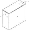
图2描述本发明一个实施例的一个合并环境光的平视显示器的外部示意图。FIG. 2 depicts an external schematic view of a head-up display incorporating ambient light according to an embodiment of the present invention.
图3描述本发明的一个平视显示器实施例内的光学器件示意图。Figure 3 depicts a schematic diagram of the optics within an embodiment of the head-up display of the present invention.
图4描述图2平视显示器的内部构造。FIG. 4 depicts the internal structure of the head-up display of FIG. 2 .
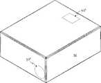
图5是本发明另一个实施例的一个合并环境光的平视显示器的外部示意图。FIG. 5 is an external schematic diagram of a head-up display incorporating ambient light according to another embodiment of the present invention.
图6描述图5平视显示器的内部构造。FIG. 6 depicts the internal structure of the head-up display of FIG. 5 .
【发明详述】【Detailed description of the invention】
附图中,在每个示意图里相同号码表示相同或类似的特征。图1描述本发明一个实施例的一个平视显示器10的示意图。如图1所示,本发明收集环境光以用来增强平视显示器里的显示亮度。环境光与一个电驱动光源如发光二极管(LED)或激光二极管的可视光聚合在一起,用来形成一幅具有增强亮度级的图像。In the drawings, like numbers indicate like or similar features throughout each illustration. FIG. 1 depicts a schematic diagram of a head-up
当本发明用于图1所述的车辆时,一个由平视显示器(HUD)单元10形成的图像20将被投影到扩散膜220上,并被反射到挡风玻璃30上,然后其让驾驶者看到。可选择地,HUD单元可以安装在仪表板的顶部,因为这样能够对驾驶者前端的视野构成最小的障碍。另外,HUD单元也可以安置在车辆的其它合适位置,如部分地或全部地安装在仪表板上,车厢顶部等。When the present invention is used in the vehicle shown in FIG. 1, an
如图2所示的HUD单元10的外部示意图。环境光通过窗口40进入单元10,投影光学器件的出口在投影仪窗口50。由于HUD单元10的紧凑设计,在车辆上的售后安装可以非常简容地完成。这种情况下,HUD 10可以形成部分导航/GPS系统,其可以简容地安装在任何车辆上。The external schematic diagram of the
用于本发明一个实施例的光学器件示意图在图3内描述。如图3所示,环境光和来自光源如一个或多个LED/激光的光,被聚合以形成一个单一的均匀光源用于HUD内。环境光100进入集光光学单元110,然后可选择地,由镜120反射,再由第一光束成形光学单元130进行整形。集光光学单元110收集环境光,并重新引导它使其落在一个指定的锥角内。集光光学单元110可以从各种光学装置中选择,如光导、非球面透镜、和菲涅耳透镜。但是,该列表并不是限制性的,任何能够有效地收集并传递环境光到HUD的光学装置都可以补充用于本发明。A schematic diagram of the optics used in one embodiment of the invention is depicted in FIG. 3 . As shown in Figure 3, ambient light and light from a light source, such as one or more LEDs/lasers, are combined to form a single uniform light source for use within the HUD. The ambient light 100 enters the light collecting
光束成形光学单元130可以包括一组共轭透镜(conjugated lenses)或TIR透镜。光束成形光学单元130的目的是在光被导向混光装置之前准直聚集的环境光。The beam shaping
另一个光源140用于发射光,以便与集光光学单元110收集的环境光聚合。光源140可以是一个单色LED、多色LED、激光、白炽灯、卤素灯、弧光灯、或任何其它足够照明液晶元件的发光器、或以上发光器的任何组合。Another
接着,光源140的光进入第二光束成形光学单元150。当使用一个可选的反馈控制系统时,光源的光强度是可以根据收集的环境光强度而进行调整的。第二光束成形光学单元的目的是在将光导向混光单元170之前准直光源的光。Then, the light of the
反射镜160的安置和朝向会使得光源140的光和收集的环境光被导向混光单元170。反射镜160可以包括平面镜、曲面镜、直角棱镜、或多个以上透镜和/或多个以上透镜组合。反射镜160可以是单个单元或作为两个或多个独立单元。反射镜也可以由直角棱镜或其它光学器件代替,只要其能够改变光的方向。The placement and orientation of the
对液晶元件而言,入射光的均匀度是非常重要的,混光单元170可以从各种装置中选择,只要其能够混合光源140的光和环境光,并输出一个充分均匀的光束。这类装置包括但不限于积分光棒(integrating rod)或宏焦距集光器(macrofocal concentrator)。宏焦距集光器的例子包括复合抛物面聚光器(CPC)、复合椭球面聚光器(CEC)和复合双曲面聚光器(CHC)。但是,任何能够均匀混合这两个光源并提供一个均匀输出的光学元件都可以补充作为本发明的混光单元170。为了进一步增强环境光和光源140的光的均匀化,利用混合器,混光单元的侧壁可以发散性地反射光。在混光单元内,聚集的和准直的环境光与来自光源140的准直光混合在一起。混光元件的功能是混合并均匀化在混光元件内的所有光,并控制将被投影到反射显示器单元上的混合光的扩散角。结果,从混光元件输出的光是被充分均匀化的。For the liquid crystal element, the uniformity of the incident light is very important, the
接着,从混光元件170出来的混合光进入到聚光单元180内。聚光单元180可以包括一组共轭透镜或一组自由曲面透镜。可选择地,如果有预偏器(pre-polarizer),聚光单元将混合光导向预偏器,否则,混合光一旦从聚光单元180中出来,被导向偏振分光器(PBS)190。Then, the mixed light from the
预偏器的安置和朝向会使得仅有PBS阻止偏振态(blockpolarization)的光被透过。因此,透过预偏器的光将在PBS上被反射到反射显示器单元200。The placement and orientation of the prepolarizer is such that only the PBS blocks polarization of light from being transmitted. Therefore, light transmitted through the prepolarizer will be reflected on the PBS to
在PBS 190上,具有特别偏振的光被完全反射,而具有正交偏振的光被透过。偏振可以是线型、圆型、或胆甾型(cholesteric)。线型偏振器的例子包括聚合物多层偏振膜(polymeric multiple layer polarizing film)或有线栅偏振器(wire grid polarizer)。将会注意到,使用胆甾型偏振器也可能需要引入四分波延迟器,以便在线型和圆型偏振之间转换光。例如,如果反射显示器单元在线型偏振光上运行,并且光源的光也是线性偏振,那么胆甾型偏振器可以在其前表面上有一个四分波延迟层,以便使光圆形偏振后再入射到胆甾型偏振器的表面。此外,四分波延迟器会使反射光线性偏振后再传播到反射图像显示器单元。如果来自光源的光是圆形偏振,那么在反射图像显示器单元输入上可以有一个四分波延迟器,从而使胆甾型偏振器反射的光线性偏振。此外,PBS 190可以在一个或多个方向上是平坦的或弯曲的。On
具有PBS的阻止偏振态(block polarization)的光将在PBS 190上被反射,并将行进到反射显示器单元200。反射显示器单元可以是一个液晶显示器(LCD)单元,如硅基液晶(LCoS)显示器、数字光处理(DLP)显示器、或任何其它合适的显示器单元。当本发明运行时,一个视频信号输入到反射显示器单元200,该视频信号可能是从一个GPS单元、一个导航单元、一个或多个仪表板装置(如速度计、测速计、油量表)、机载计算机、或任何能够产生合适视频信号用于反射显示器单元的装置产生的。反射显示器单元200通过偏振旋转,能够空间地调制入射光。反射光包括PBS阻止偏振态和PBS通过偏振态(pass polarizations)的光。仅PBS 190通过偏振态的光,如图像光,将通过PBS被传输到投影仪单元210。Light with block polarization of the PBS will be reflected on the
如图1所示,投影仪单元210投影图像光在扩散膜220上。扩散膜可以被连接到投影仪单元。一个真实的镜像将通过扩散膜形成,并且该真实镜像将被反射到在挡风玻璃上而进入观察者视野。可以理解,扩散膜220的使用是可选择性的,可以设置反射显示器200与投影光学器件以便直接将一个合适图像直接从投影仪单元210显示到挡风玻璃上。As shown in FIG. 1 , the
图4描述图2平视显示器10的光学元件的内部配置。图4元件类似于图3所示的那些元件,如对应的元件号码所示。FIG. 4 depicts the internal configuration of the optical components of the head-up
图5描述本发明平视显示器的一个卧式实施例10的外部示意图。如之前的实施例,环境光进入窗口40,图像光是从投影口50出来。图6描述在平视显示器10内部的光学元件配置。图6元件类似于图3所示的那些元件,如对应的元件号码所示。如图6所示,用于环境光的集光光学器件110的配置允许HUD高度低于图2HUD的高度。该实施例特别适用于售后安装在车辆仪表板上,因为其更能够提供更好的视野。FIG. 5 depicts an external schematic view of a
应该理解,本发明上述元件的实际位置和朝向可以调整以改变图像的尺寸、亮度和清晰度。It should be understood that the actual positions and orientations of the above elements of the present invention can be adjusted to change the size, brightness and clarity of the image.
尽管本发明已经在上下文里描述了专为机动车辆设计的用于显示相关驾驶信息如车辆速度、发动机速度(rpm)和全球定位系统(GPS)数据的平视显示器(HUD)单元,应该理解,本发明同样适用于其它交通工具涵义下的平视显示器,如航空器和船舶。此外,本发明同样适用于其它需要增强照明的情况,如头盔显示单元或微型投影仪。Although the present invention has been described in the context of a head-up display (HUD) unit designed for motor vehicles to display relevant driving information such as vehicle speed, engine speed (rpm) and global positioning system (GPS) data, it should be understood that the present invention The invention is also applicable to head-up displays within the meaning of other vehicles, such as aircraft and ships. In addition, the present invention is equally applicable to other situations that require enhanced lighting, such as helmet display units or micro-projectors.
尽管已经描述了本发明的特别实施例,应该理解,本发明不受限于在此所述的具体构造,从以上述描述可以明显地对其作出各种修改、改变和变化。这些修改、改变和变换被看作是所附权利要求内阐述的本发明范围的一部分。Although particular embodiments of the invention have been described, it is to be understood that the invention is not limited to the specific constructions described herein, and various modifications, changes and variations will be apparent from the foregoing description. Such modifications, changes and transformations are considered to be part of the scope of the present invention as set forth in the appended claims.
Claims (19)
Translated fromChinesePriority Applications (1)
| Application Number | Priority Date | Filing Date | Title |
|---|---|---|---|
| CN2010102015323ACN101876753B (en) | 2010-06-03 | 2010-06-03 | Hybrid illumination system for head-up display |
Applications Claiming Priority (1)
| Application Number | Priority Date | Filing Date | Title |
|---|---|---|---|
| CN2010102015323ACN101876753B (en) | 2010-06-03 | 2010-06-03 | Hybrid illumination system for head-up display |
Publications (2)
| Publication Number | Publication Date |
|---|---|
| CN101876753A CN101876753A (en) | 2010-11-03 |
| CN101876753Btrue CN101876753B (en) | 2012-06-27 |
Family
ID=43019352
Family Applications (1)
| Application Number | Title | Priority Date | Filing Date |
|---|---|---|---|
| CN2010102015323AExpired - Fee RelatedCN101876753B (en) | 2010-06-03 | 2010-06-03 | Hybrid illumination system for head-up display |
Country Status (1)
| Country | Link |
|---|---|
| CN (1) | CN101876753B (en) |
Families Citing this family (17)
| Publication number | Priority date | Publication date | Assignee | Title |
|---|---|---|---|---|
| JP5873707B2 (en)* | 2011-12-15 | 2016-03-01 | 矢崎総業株式会社 | Head-up display device |
| FR2995089B1 (en)* | 2012-08-30 | 2015-08-21 | Optinvent | OPTICAL DEVICE AND METHOD FOR MANUFACTURING SUCH A DEVICE |
| JP6107047B2 (en)* | 2012-10-24 | 2017-04-05 | 日本精機株式会社 | Head-up display device |
| TWI509287B (en)* | 2014-06-19 | 2015-11-21 | Lu Ho | Head up display |
| CN104199188A (en)* | 2014-09-01 | 2014-12-10 | 望新(上海)科技有限公司 | Vehicle HUD light source system |
| JP6550716B2 (en)* | 2014-10-16 | 2019-07-31 | 日本精機株式会社 | Head-up display device |
| FR3029648B1 (en)* | 2014-12-05 | 2018-02-02 | Valeo Comfort And Driving Assistance | HEAD-UP DISPLAY WITH ADJUSTABLE VIEW-WINDOW |
| CN105807847A (en)* | 2014-12-30 | 2016-07-27 | 中国舰船研究设计中心 | Ship navigation information display apparatus used for inwards tilted front wall of cab |
| JP6551068B2 (en)* | 2015-09-01 | 2019-07-31 | オムロン株式会社 | Display device |
| US10012836B2 (en)* | 2016-05-23 | 2018-07-03 | Lg Electronics Inc. | Head up display for vehicle |
| EP3505990B1 (en)* | 2016-08-29 | 2023-05-24 | Kyocera Corporation | Light source apparatus, display apparatus, and moving body |
| CN106547094A (en)* | 2016-11-25 | 2017-03-29 | 刘涛 | The equipment that new line shows is realized using shield glass |
| CN107085306B (en)* | 2017-06-15 | 2023-07-04 | 优奈柯恩(北京)科技有限公司 | Display device for augmented reality device, augmented reality device, and head-up display |
| CN109901295A (en)* | 2017-12-08 | 2019-06-18 | 苏州苏大维格光电科技股份有限公司 | Optical waveguide film, head-up display and head-up display system |
| JP2019174802A (en)* | 2018-03-28 | 2019-10-10 | 株式会社リコー | Control device, display device, display system, movable body, control method, and program |
| WO2021226772A1 (en)* | 2020-05-11 | 2021-11-18 | 上海欧菲智能车联科技有限公司 | Surround view display method and apparatus, computer device, and storage medium |
| CN116047845A (en)* | 2023-02-27 | 2023-05-02 | 深圳市瀚思通汽车电子有限公司 | Projection optical machine imaging system for automobile head-up display |
Family Cites Families (3)
| Publication number | Priority date | Publication date | Assignee | Title |
|---|---|---|---|---|
| CN101349833B (en)* | 2007-07-20 | 2011-11-23 | 奇美电子股份有限公司 | Apparatus and method for adjusting light ray and backlight module unit and LCD device using the same |
| CN101354494B (en)* | 2007-07-26 | 2010-06-02 | 和硕联合科技股份有限公司 | Electronic device |
| JP2009229752A (en)* | 2008-03-21 | 2009-10-08 | Toshiba Corp | Display device, display method and headup display |
- 2010
- 2010-06-03CNCN2010102015323Apatent/CN101876753B/ennot_activeExpired - Fee Related
Also Published As
| Publication number | Publication date |
|---|---|
| CN101876753A (en) | 2010-11-03 |
Similar Documents
| Publication | Publication Date | Title |
|---|---|---|
| CN101876753B (en) | Hybrid illumination system for head-up display | |
| US8436952B2 (en) | Hybrid illumination system for head-up display | |
| US20160147074A1 (en) | Image display apparatus | |
| CN106233185B (en) | Head-up display | |
| JP6027727B2 (en) | Vehicle display device | |
| US9400386B2 (en) | Head-up display having an image-generating device for generating an image and optical system for projecting the image | |
| EP3118667A1 (en) | Display device | |
| US20160231565A1 (en) | Image display device | |
| US9580015B2 (en) | Image display device | |
| US10793003B2 (en) | Head-up display device | |
| JP2019049581A (en) | Head-up display device and image projection unit | |
| JP2008068766A (en) | Vehicular display apparatus | |
| WO2017203916A1 (en) | Head-up display device | |
| CN104854500A (en) | Device and method for emitting a light beam intended to form an image, projection system, and display using said device | |
| WO2016189871A1 (en) | Light source unit and projection device | |
| WO2016121309A1 (en) | Polarization conversion element and optical device using same | |
| JP2018004673A (en) | Illumination device | |
| JP4984452B2 (en) | Spatial light modulation optical device, virtual image display device using the same, and projection type image display device | |
| JP6982816B2 (en) | Image display device, virtual image display device, moving object | |
| JP6330944B2 (en) | Intermediate image forming device | |
| JP2025116303A (en) | Head-up display device | |
| WO2024057971A1 (en) | Image projecting device | |
| JP2023057027A (en) | Image generation unit and head-up display device | |
| JP2024179345A (en) | Head-up display and vehicle | |
| JP2025129495A (en) | Head-up display device and control method for head-up display device |
Legal Events
| Date | Code | Title | Description |
|---|---|---|---|
| C06 | Publication | ||
| PB01 | Publication | ||
| C10 | Entry into substantive examination | ||
| SE01 | Entry into force of request for substantive examination | ||
| C14 | Grant of patent or utility model | ||
| GR01 | Patent grant | ||
| CF01 | Termination of patent right due to non-payment of annual fee | ||
| CF01 | Termination of patent right due to non-payment of annual fee | Granted publication date:20120627 |