CN101873885B - Thin film valve device and its controlling apparatus - Google Patents
Thin film valve device and its controlling apparatusDownload PDFInfo
- Publication number
- CN101873885B CN101873885BCN2008801175186ACN200880117518ACN101873885BCN 101873885 BCN101873885 BCN 101873885BCN 2008801175186 ACN2008801175186 ACN 2008801175186ACN 200880117518 ACN200880117518 ACN 200880117518ACN 101873885 BCN101873885 BCN 101873885B
- Authority
- CN
- China
- Prior art keywords
- membrane valve
- membrane
- valve device
- hole
- adhesive
- Prior art date
- Legal status (The legal status is an assumption and is not a legal conclusion. Google has not performed a legal analysis and makes no representation as to the accuracy of the status listed.)
- Expired - Fee Related
Links
Images


Classifications
- F—MECHANICAL ENGINEERING; LIGHTING; HEATING; WEAPONS; BLASTING
- F16—ENGINEERING ELEMENTS AND UNITS; GENERAL MEASURES FOR PRODUCING AND MAINTAINING EFFECTIVE FUNCTIONING OF MACHINES OR INSTALLATIONS; THERMAL INSULATION IN GENERAL
- F16K—VALVES; TAPS; COCKS; ACTUATING-FLOATS; DEVICES FOR VENTING OR AERATING
- F16K99/00—Subject matter not provided for in other groups of this subclass
- F16K99/0001—Microvalves
- G—PHYSICS
- G01—MEASURING; TESTING
- G01N—INVESTIGATING OR ANALYSING MATERIALS BY DETERMINING THEIR CHEMICAL OR PHYSICAL PROPERTIES
- G01N35/00—Automatic analysis not limited to methods or materials provided for in any single one of groups G01N1/00 - G01N33/00; Handling materials therefor
- G01N35/08—Automatic analysis not limited to methods or materials provided for in any single one of groups G01N1/00 - G01N33/00; Handling materials therefor using a stream of discrete samples flowing along a tube system, e.g. flow injection analysis
- B—PERFORMING OPERATIONS; TRANSPORTING
- B01—PHYSICAL OR CHEMICAL PROCESSES OR APPARATUS IN GENERAL
- B01L—CHEMICAL OR PHYSICAL LABORATORY APPARATUS FOR GENERAL USE
- B01L3/00—Containers or dishes for laboratory use, e.g. laboratory glassware; Droppers
- B01L3/50—Containers for the purpose of retaining a material to be analysed, e.g. test tubes
- B01L3/502—Containers for the purpose of retaining a material to be analysed, e.g. test tubes with fluid transport, e.g. in multi-compartment structures
- B01L3/5027—Containers for the purpose of retaining a material to be analysed, e.g. test tubes with fluid transport, e.g. in multi-compartment structures by integrated microfluidic structures, i.e. dimensions of channels and chambers are such that surface tension forces are important, e.g. lab-on-a-chip
- B01L3/502738—Containers for the purpose of retaining a material to be analysed, e.g. test tubes with fluid transport, e.g. in multi-compartment structures by integrated microfluidic structures, i.e. dimensions of channels and chambers are such that surface tension forces are important, e.g. lab-on-a-chip characterised by integrated valves
- B—PERFORMING OPERATIONS; TRANSPORTING
- B01—PHYSICAL OR CHEMICAL PROCESSES OR APPARATUS IN GENERAL
- B01L—CHEMICAL OR PHYSICAL LABORATORY APPARATUS FOR GENERAL USE
- B01L7/00—Heating or cooling apparatus; Heat insulating devices
- B—PERFORMING OPERATIONS; TRANSPORTING
- B81—MICROSTRUCTURAL TECHNOLOGY
- B81B—MICROSTRUCTURAL DEVICES OR SYSTEMS, e.g. MICROMECHANICAL DEVICES
- B81B3/00—Devices comprising flexible or deformable elements, e.g. comprising elastic tongues or membranes
- F—MECHANICAL ENGINEERING; LIGHTING; HEATING; WEAPONS; BLASTING
- F16—ENGINEERING ELEMENTS AND UNITS; GENERAL MEASURES FOR PRODUCING AND MAINTAINING EFFECTIVE FUNCTIONING OF MACHINES OR INSTALLATIONS; THERMAL INSULATION IN GENERAL
- F16K—VALVES; TAPS; COCKS; ACTUATING-FLOATS; DEVICES FOR VENTING OR AERATING
- F16K31/00—Actuating devices; Operating means; Releasing devices
- F—MECHANICAL ENGINEERING; LIGHTING; HEATING; WEAPONS; BLASTING
- F16—ENGINEERING ELEMENTS AND UNITS; GENERAL MEASURES FOR PRODUCING AND MAINTAINING EFFECTIVE FUNCTIONING OF MACHINES OR INSTALLATIONS; THERMAL INSULATION IN GENERAL
- F16K—VALVES; TAPS; COCKS; ACTUATING-FLOATS; DEVICES FOR VENTING OR AERATING
- F16K49/00—Means in or on valves for heating or cooling
- F—MECHANICAL ENGINEERING; LIGHTING; HEATING; WEAPONS; BLASTING
- F16—ENGINEERING ELEMENTS AND UNITS; GENERAL MEASURES FOR PRODUCING AND MAINTAINING EFFECTIVE FUNCTIONING OF MACHINES OR INSTALLATIONS; THERMAL INSULATION IN GENERAL
- F16K—VALVES; TAPS; COCKS; ACTUATING-FLOATS; DEVICES FOR VENTING OR AERATING
- F16K99/00—Subject matter not provided for in other groups of this subclass
- F16K99/0001—Microvalves
- F16K99/0003—Constructional types of microvalves; Details of the cutting-off member
- F16K99/0015—Diaphragm or membrane valves
- F—MECHANICAL ENGINEERING; LIGHTING; HEATING; WEAPONS; BLASTING
- F16—ENGINEERING ELEMENTS AND UNITS; GENERAL MEASURES FOR PRODUCING AND MAINTAINING EFFECTIVE FUNCTIONING OF MACHINES OR INSTALLATIONS; THERMAL INSULATION IN GENERAL
- F16K—VALVES; TAPS; COCKS; ACTUATING-FLOATS; DEVICES FOR VENTING OR AERATING
- F16K99/00—Subject matter not provided for in other groups of this subclass
- F16K99/0001—Microvalves
- F16K99/0034—Operating means specially adapted for microvalves
- F16K99/0042—Electric operating means therefor
- F16K99/0046—Electric operating means therefor using magnets
- G—PHYSICS
- G01—MEASURING; TESTING
- G01N—INVESTIGATING OR ANALYSING MATERIALS BY DETERMINING THEIR CHEMICAL OR PHYSICAL PROPERTIES
- G01N35/00—Automatic analysis not limited to methods or materials provided for in any single one of groups G01N1/00 - G01N33/00; Handling materials therefor
- G01N35/10—Devices for transferring samples or any liquids to, in, or from, the analysis apparatus, e.g. suction devices, injection devices
- G01N35/1009—Characterised by arrangements for controlling the aspiration or dispense of liquids
- B—PERFORMING OPERATIONS; TRANSPORTING
- B01—PHYSICAL OR CHEMICAL PROCESSES OR APPARATUS IN GENERAL
- B01L—CHEMICAL OR PHYSICAL LABORATORY APPARATUS FOR GENERAL USE
- B01L2300/00—Additional constructional details
- B01L2300/08—Geometry, shape and general structure
- B01L2300/0861—Configuration of multiple channels and/or chambers in a single devices
- B01L2300/087—Multiple sequential chambers
- B—PERFORMING OPERATIONS; TRANSPORTING
- B01—PHYSICAL OR CHEMICAL PROCESSES OR APPARATUS IN GENERAL
- B01L—CHEMICAL OR PHYSICAL LABORATORY APPARATUS FOR GENERAL USE
- B01L2300/00—Additional constructional details
- B01L2300/08—Geometry, shape and general structure
- B01L2300/0861—Configuration of multiple channels and/or chambers in a single devices
- B01L2300/0874—Three dimensional network
- B—PERFORMING OPERATIONS; TRANSPORTING
- B01—PHYSICAL OR CHEMICAL PROCESSES OR APPARATUS IN GENERAL
- B01L—CHEMICAL OR PHYSICAL LABORATORY APPARATUS FOR GENERAL USE
- B01L2300/00—Additional constructional details
- B01L2300/08—Geometry, shape and general structure
- B01L2300/0887—Laminated structure
- B—PERFORMING OPERATIONS; TRANSPORTING
- B01—PHYSICAL OR CHEMICAL PROCESSES OR APPARATUS IN GENERAL
- B01L—CHEMICAL OR PHYSICAL LABORATORY APPARATUS FOR GENERAL USE
- B01L2300/00—Additional constructional details
- B01L2300/18—Means for temperature control
- B01L2300/1805—Conductive heating, heat from thermostatted solids is conducted to receptacles, e.g. heating plates, blocks
- B01L2300/1827—Conductive heating, heat from thermostatted solids is conducted to receptacles, e.g. heating plates, blocks using resistive heater
- B—PERFORMING OPERATIONS; TRANSPORTING
- B01—PHYSICAL OR CHEMICAL PROCESSES OR APPARATUS IN GENERAL
- B01L—CHEMICAL OR PHYSICAL LABORATORY APPARATUS FOR GENERAL USE
- B01L2400/00—Moving or stopping fluids
- B01L2400/04—Moving fluids with specific forces or mechanical means
- B01L2400/0403—Moving fluids with specific forces or mechanical means specific forces
- B01L2400/0409—Moving fluids with specific forces or mechanical means specific forces centrifugal forces
- B—PERFORMING OPERATIONS; TRANSPORTING
- B01—PHYSICAL OR CHEMICAL PROCESSES OR APPARATUS IN GENERAL
- B01L—CHEMICAL OR PHYSICAL LABORATORY APPARATUS FOR GENERAL USE
- B01L2400/00—Moving or stopping fluids
- B01L2400/06—Valves, specific forms thereof
- B01L2400/0677—Valves, specific forms thereof phase change valves; Meltable, freezing, dissolvable plugs; Destructible barriers
- B01L2400/0683—Valves, specific forms thereof phase change valves; Meltable, freezing, dissolvable plugs; Destructible barriers mechanically breaking a wall or membrane within a channel or chamber
- F—MECHANICAL ENGINEERING; LIGHTING; HEATING; WEAPONS; BLASTING
- F16—ENGINEERING ELEMENTS AND UNITS; GENERAL MEASURES FOR PRODUCING AND MAINTAINING EFFECTIVE FUNCTIONING OF MACHINES OR INSTALLATIONS; THERMAL INSULATION IN GENERAL
- F16K—VALVES; TAPS; COCKS; ACTUATING-FLOATS; DEVICES FOR VENTING OR AERATING
- F16K99/00—Subject matter not provided for in other groups of this subclass
- F16K2099/0082—Microvalves adapted for a particular use
- F16K2099/0084—Chemistry or biology, e.g. "lab-on-a-chip" technology
- Y—GENERAL TAGGING OF NEW TECHNOLOGICAL DEVELOPMENTS; GENERAL TAGGING OF CROSS-SECTIONAL TECHNOLOGIES SPANNING OVER SEVERAL SECTIONS OF THE IPC; TECHNICAL SUBJECTS COVERED BY FORMER USPC CROSS-REFERENCE ART COLLECTIONS [XRACs] AND DIGESTS
- Y10—TECHNICAL SUBJECTS COVERED BY FORMER USPC
- Y10T—TECHNICAL SUBJECTS COVERED BY FORMER US CLASSIFICATION
- Y10T137/00—Fluid handling
- Y10T137/7722—Line condition change responsive valves
- Y10T137/7737—Thermal responsive
- Y—GENERAL TAGGING OF NEW TECHNOLOGICAL DEVELOPMENTS; GENERAL TAGGING OF CROSS-SECTIONAL TECHNOLOGIES SPANNING OVER SEVERAL SECTIONS OF THE IPC; TECHNICAL SUBJECTS COVERED BY FORMER USPC CROSS-REFERENCE ART COLLECTIONS [XRACs] AND DIGESTS
- Y10—TECHNICAL SUBJECTS COVERED BY FORMER USPC
- Y10T—TECHNICAL SUBJECTS COVERED BY FORMER US CLASSIFICATION
- Y10T436/00—Chemistry: analytical and immunological testing
- Y10T436/25—Chemistry: analytical and immunological testing including sample preparation
- Y10T436/2575—Volumetric liquid transfer
Landscapes
- Engineering & Computer Science (AREA)
- Chemical & Material Sciences (AREA)
- General Engineering & Computer Science (AREA)
- Dispersion Chemistry (AREA)
- Mechanical Engineering (AREA)
- Health & Medical Sciences (AREA)
- Analytical Chemistry (AREA)
- Clinical Laboratory Science (AREA)
- Chemical Kinetics & Catalysis (AREA)
- General Health & Medical Sciences (AREA)
- General Physics & Mathematics (AREA)
- Pathology (AREA)
- Physics & Mathematics (AREA)
- Biochemistry (AREA)
- Life Sciences & Earth Sciences (AREA)
- Hematology (AREA)
- Immunology (AREA)
- Microelectronics & Electronic Packaging (AREA)
- Computer Hardware Design (AREA)
- Apparatus Associated With Microorganisms And Enzymes (AREA)
- Temperature-Responsive Valves (AREA)
- Automatic Analysis And Handling Materials Therefor (AREA)
- Electrically Driven Valve-Operating Means (AREA)
- Micromachines (AREA)
- Details Of Valves (AREA)
- Magnetically Actuated Valves (AREA)
Abstract
Description
Translated fromChinese技术领域technical field
本发明构思涉及控制诊断化验器件(diagnostic assay device)中流体的流量和流速,该诊断化验器件能够检测流体中痕量(trace amount)的材料。The inventive concept relates to controlling the flow rate and flow rate of a fluid in a diagnostic assay device capable of detecting trace amounts of material in the fluid.
本发明构思涉及用于控制流体的流量和流速的薄膜阀器件(thin filmvalve)和薄膜阀控制装置,更具体地,本发明构思涉及一种薄膜阀器件以及一种薄膜阀控制装置,在该薄膜阀器件中孔(hole)和阀由于离心力和热产生器件产生的热而打开和关闭。The inventive concept relates to a thin film valve device (thin film valve) and a thin film valve control device for controlling the flow rate and flow velocity of a fluid, and more particularly, the inventive concept relates to a thin film valve device and a thin film valve control device in which the thin film A hole and a valve in the valve device are opened and closed due to centrifugal force and heat generated by the heat generating device.
根据本发明构思实施例的薄膜阀器件和薄膜阀控制装置可用于构造芯片上诊断实验室(diagnostic lab-on-a-chip)和可旋转生物盘(bio-disc)的阀及其控制装置,该芯片上诊断实验室能够检测流体中痕量的材料,诸如蛋白质芯片和DNA芯片的生物芯片集成在该生物盘中。例如,通过修改普通盘器件(common disc device)诸如CD-ROM和DVD,根据本发明构思实施例的薄膜阀器件和薄膜阀控制装置可应用于构造微阀器件,该微阀器件用于打开和关闭形成于主体中的沟道和孔,其中该主体形成为薄膜。The membrane valve device and the membrane valve control device according to embodiments of the present invention can be used to construct valves and control devices for diagnostic lab-on-a-chip and rotatable bio-discs on a chip, The diagnostic laboratory on a chip is capable of detecting trace amounts of materials in fluids, and biochips such as protein chips and DNA chips are integrated in the biodisc. For example, by modifying common disc devices (common disc devices) such as CD-ROM and DVD, the membrane valve device and the membrane valve control device according to the embodiment of the inventive concept can be applied to construct a microvalve device for opening and Channels and holes formed in a body formed as a thin film are closed.
背景技术Background technique
到此为止,对于用于检测流体中少量分析物的大多数诊断化验装置,已经设计了多样品制备和试剂自动添加装置,或者用于同时(并行或串行处理)识别大量样品的多样品化验装置,以提高效率并降低成本。该自动试剂制备器件和自动化验装置通常集成到单个薄膜型装置中。该薄膜型诊断化验装置能够利用痕量的样品和试剂在一个小时内自动或半自动地准确分析数百个分析物。该薄膜型化验装置需要用于自动供应样品或试剂(酶和缓冲剂)的阀。然而,设计这种用于薄膜型化验装置的阀是复杂的。因此,需要设计一种适于薄膜型化验装置的简单的薄膜阀。To date, multiple sample preparation and automated reagent addition devices have been designed for most diagnostic assays for the detection of small numbers of analytes in fluids, or for multiple sample assays that identify a large number of samples simultaneously (parallel or serial processing) devices to increase efficiency and reduce costs. The automated reagent preparation device and the automated assay device are usually integrated into a single thin-film type device. The thin-film diagnostic assay is capable of accurately analyzing hundreds of analytes within an hour, automatically or semi-automatically, using trace amounts of samples and reagents. The membrane-type assay device requires valves for automatically supplying samples or reagents (enzymes and buffers). However, designing such valves for membrane-type assay devices is complicated. Therefore, there is a need to design a simple membrane valve suitable for membrane-type assay devices.
对于作为薄膜基板的CD和DVD,标准的CD由例如12cm的聚碳酸酯基板、反射金属层和保护漆涂层(protective lacquer coating)形成。DVD、CD和CD-ROM的格式在ISO 9660中描述。聚碳酸酯基板是光学质量的透明聚碳酸酯基板。DVD和CD中的数据层可以是聚碳酸酯基板的一部分,数据能够在注射成型工艺中通过压模(stamper)雕刻为一连串凹坑(pit)的形式。冲压母盘(stamping master)主要是玻璃。该聚碳酸酯基板可以被修改为薄膜型诊断化验装置(诸如生物盘),其检测流体中痕量的材料。在此情形下,在注射成型工艺中,在盘的表面中,可以形成作为流体流动路径的沟道以及作为缓冲贮液器的腔室,而不形成凹坑。此外,需要一种能够平稳地控制流经形成于薄膜型盘中的通道的流体的流量和流速的薄膜型阀。For CDs and DVDs as film substrates, a standard CD is formed from, for example, a 12 cm polycarbonate substrate, a reflective metal layer and a protective lacquer coating. The format of DVD, CD and CD-ROM is described in ISO 9660. Polycarbonate Substrate is an optical quality clear polycarbonate substrate. The data layer in DVDs and CDs can be part of a polycarbonate substrate, and the data can be engraved as a series of pits by a stamper in an injection molding process. The stamping master is mainly glass. The polycarbonate substrate can be modified into a thin-film type diagnostic assay device such as a bio-disc that detects trace amounts of the material in a fluid. In this case, in the surface of the disc, channels as fluid flow paths and cavities as buffer reservoirs can be formed without forming dimples in the injection molding process. In addition, there is a need for a membrane type valve capable of smoothly controlling the flow rate and flow rate of fluid flowing through channels formed in the membrane type disk.
在下文中,检测流体中材料的痕量的芯片上诊断实验室、将薄膜阀与生物芯片(诸如蛋白质芯片和DNA芯片)集成在一起的盘以及其中集成薄膜阀并进行生物和化学处理以检测流体中痕量的材料的诊断盘被统称为“生物盘”或“薄膜阀器件”,其中这些器件通过修改普通盘诸如CD-ROM、DVD等制成。In the following, laboratory-on-a-chip diagnostics that detect trace amounts of materials in fluids, discs that integrate membrane valves with biochips such as protein chips and DNA chips, and in which membrane valves are integrated and processed biologically and chemically to detect fluids Diagnostic discs of materials in trace amounts are collectively referred to as "bio-discs" or "membrane valve devices", where these devices are made by modifying common discs such as CD-ROM, DVD, etc.
利用离心力使注入到盘的注入孔中的流体样品在盘表面中流动的器件以及利用离心力使注入到盘的注入孔中的流体样品流动到通道和腔室中以分离样品的器件是众所周知的。然而,这些器件不能克服构造薄膜型结构的困难,从而不能确保对流速的精确控制。Devices that use centrifugal force to flow a fluid sample injected into an injection hole of a disk in the surface of the disk and devices that use centrifugal force to flow a fluid sample injected into the injection hole of a disk into channels and chambers to separate the sample are well known. However, these devices cannot overcome the difficulty of constructing thin-film-type structures to ensure precise control of the flow rate.
利用电磁体的一般阀使用汽缸(cylinder)或活塞打开或关闭通道,其中汽缸或活塞由于磁力而移动。为了增强磁力以移动汽缸或活塞,需要适当尺寸的铁电芯(ferroelectric core)和缠绕在芯周围的多条线。此外,打开或关闭阀以及移动汽缸或活塞需要大量的电力。使用电磁体的阀由于电磁体的尺寸而不能构造为薄膜型阀。该阀由于消耗大量电力而产生过量热。因而,该阀不适于成为薄膜阀。A general valve using an electromagnet opens or closes a passage using a cylinder or piston that moves due to magnetic force. To enhance the magnetic force to move a cylinder or piston, an appropriately sized ferroelectric core and multiple wires wrapped around the core are required. Additionally, it takes a lot of power to open or close valves and move cylinders or pistons. Valves using electromagnets cannot be configured as membrane-type valves due to the size of the electromagnets. The valve generates excess heat due to the large amount of power consumed. Therefore, the valve is not suitable as a membrane valve.
为了解决这些问题,在本发明构思的实施例中,除了利用由热产生装置产生的热之外,利用薄膜阀器件旋转时产生的离心力来打开阀。因此,减少了外部磁体的体积,并确保了打开阀的可靠性。此外,在打开孔而不是通道时,流体不接触阀。因而,在产生热时,流体的性质不太可能被改变。In order to solve these problems, in an embodiment of the present inventive concept, in addition to using heat generated by the heat generating device, a centrifugal force generated when the membrane valve device is rotated is used to open the valve. Therefore, the volume of the external magnet is reduced and the reliability of opening the valve is ensured. Furthermore, fluid does not contact the valve when holes are opened instead of channels. Thus, the properties of the fluid are less likely to be altered when heat is generated.
要求生物盘将液相材料储存在腔室中以在整个循环周期(period ofcirculation)中都是稳定的。然而,对于长时间的循环,生物盘的主体由于环境因素诸如温度而收缩和膨胀,这会在阀中导致间隙。因此,存储在腔室中的流体通过阀中的间隙蒸发,这降低了阀密封的可靠性。为了解决该问题,本发明构思的实施例提供了一种如下所述关闭和打开孔的薄膜阀器件。涂覆有粘合剂(胶水试剂)的珠(球)塞、非磁性塞、磁性塞或热收缩塞或者薄膜胶带附接到孔以在循环期间紧密地封闭孔。此外,当打开孔时,粘合剂的粘接强度(粘合力)利用由热产生装置产生的热而降低,然后珠(球)塞、非磁性塞、磁性塞、热收缩塞或者薄膜胶带利用流体的液压力而与孔分离,该液压力由于离心力而产生。Bio-discs are required to store liquid phase materials in chambers to be stable throughout the period of circulation. However, for long cycles, the body of the bio-disc contracts and expands due to environmental factors such as temperature, which can cause gaps in the valve. Therefore, the fluid stored in the chamber evaporates through the gap in the valve, which reduces the reliability of the valve seal. To solve this problem, embodiments of the inventive concept provide a thin film valve device that closes and opens pores as described below. Bead (ball) plugs coated with adhesive (glue reagent), non-magnetic plugs, magnetic plugs or heat shrink plugs or film tape are attached to the wells to tightly seal the wells during cycling. In addition, when the hole is opened, the adhesive strength (cohesive force) of the adhesive is reduced by the heat generated by the heat generating device, and then the bead (ball) plug, non-magnetic plug, magnetic plug, heat shrinkable plug, or film tape The separation from the pores is achieved by the hydraulic force of the fluid, which is generated due to centrifugal force.
在下文中,用于打开和关闭孔的珠(球)塞、非磁性塞、磁性塞、热收缩塞以及由薄膜胶带形成的孔封闭膜被统称为薄膜阀。Hereinafter, bead (ball) plugs, non-magnetic plugs, magnetic plugs, heat-shrinkable plugs, and hole-closing films formed of film tapes for opening and closing holes are collectively referred to as film valves.
薄膜阀形成为薄膜。此外,用作薄膜阀的涂覆试剂的粘合剂是柔性的以适应薄膜阀器件的主体根据环境因素诸如温度的膨胀和收缩,从而在循环周期期间防止由于主体的膨胀和收缩而引起的密封问题。A membrane valve is formed as a membrane. In addition, the adhesive used as a coating agent for the membrane valve is flexible to accommodate the expansion and contraction of the body of the membrane valve device according to environmental factors such as temperature, thereby preventing sealing due to the expansion and contraction of the body during cycle cycles. question.
根据本发明构思实施例的薄膜阀器件包括薄膜形式的阀。此外,更大量的阀可以集成在单元区域中。因而,薄膜阀器件可应用于构造诸如芯片上实验室或DNA芯片的薄膜诊断器件的阀,该薄膜诊断器件能够检测流体中痕量的材料。例如,通过修改公共盘器件诸如CD-ROM、DVD等,薄膜阀器件可应用于构造阀器件,以打开和关闭薄膜阀器件的主体中的通道和孔或者控制流体的流速。A thin film valve device according to an embodiment of the inventive concept includes a valve in the form of a thin film. Furthermore, a greater number of valves can be integrated in the unit area. Thus, the thin-film valve device can be applied to the construction of valves for thin-film diagnostic devices such as lab-on-a-chip or DNA chips, which are capable of detecting trace amounts of materials in fluids. For example, by modifying common disk devices such as CD-ROM, DVD, etc., membrane valve devices can be applied to construct valve devices to open and close channels and holes in the body of the membrane valve device or to control the flow rate of fluids.
发明内容Contents of the invention
技术问题technical problem
根据本发明构思实施例的薄膜阀器件和薄膜阀控制装置可应用于构造芯片上诊断实验室和可旋转生物盘的阀及其控制装置,其中芯片上诊断实验室能够检测流体中痕量的材料,在可旋转生物盘中集成有生物芯片,诸如蛋白质芯片和DNA芯片。Membrane valve devices and membrane valve control devices according to embodiments of the present inventive concepts can be applied to construct valves and control devices for lab-on-chip and rotatable bio-discs, where lab-on-chip can detect trace amounts of materials in fluids , biochips, such as protein chips and DNA chips, are integrated in the rotatable bio-disc.
技术方案Technical solutions
本发明构思的实施例包括一种薄膜阀器件,该薄膜阀器件利用离心力和由热产生装置产生的热来打开由珠(球)塞、热收缩塞、非磁性塞或磁性塞封闭的孔。Embodiments of the inventive concept include a thin film valve device that uses centrifugal force and heat generated by a heat generating device to open a hole closed by a bead (ball) plug, a heat shrinkable plug, a non-magnetic plug, or a magnetic plug.
本发明构思的另一实施例包括一种薄膜阀器件,该薄膜阀器件利用由热产生装置产生的热、离心力和/或磁力来打开由磁性塞封闭的孔。Another embodiment of the inventive concept includes a membrane valve device that utilizes heat generated by a heat generating device, centrifugal force and/or magnetic force to open a hole closed by a magnetic plug.
本发明构思的另一实施例包括一种具有可逆的打开/封闭功能的薄膜阀器件,该可逆的打开/封闭功能包括:利用由热产生装置产生的热来弱化磁性塞的粘结强度以及然后利用位于主体下方的可移动永磁体来打开由磁性塞封闭的孔;以及利用由热产生装置产生的热来恢复磁性塞的粘结强度并同时利用设置在孔上方的永磁体与磁性塞之间的吸引力而再次封闭孔。Another embodiment of the inventive concept includes a membrane valve device having a reversible opening/closing function comprising: using heat generated by a heat generating device to weaken the adhesive strength of the magnetic plug and then The hole closed by the magnetic plug is opened by using a movable permanent magnet located below the main body; and the adhesive strength of the magnetic plug is restored by using heat generated by a heat generating device and at the same time by using between the permanent magnet and the magnetic plug disposed above the hole The attractive force closes the hole again.
本发明构思的另一实施例包括一种薄膜阀器件,该薄膜阀器件利用由热产生装置产生的热来打开被热收缩塞封闭的孔或通道。Another embodiment of the inventive concept includes a membrane valve device that utilizes heat generated by a heat generating device to open a hole or passage closed by a heat shrink plug.
根据本发明构思的另一实施例,珠(球)塞、热收缩塞、磁性塞和非磁性塞的表面可以用粘合剂涂覆。According to another embodiment of the present inventive concept, the surface of the bead (ball) plug, the heat shrinkable plug, the magnetic plug and the non-magnetic plug may be coated with an adhesive.
在下文,在本发明构思的整个说明书中,粘合剂、薄膜胶带和胶带可以互换地使用。Hereinafter, adhesive, film tape, and adhesive tape may be used interchangeably throughout the specification of the present inventive concept.
本发明构思的另一实施例包括一种薄膜阀器件,其中孔被由薄膜胶带形成的孔封闭膜封闭,并且在孔封闭膜由于流体自身的液压力(或水压力)而破裂时被打开,其中流体自身的液压力(或水压力)由于热产生装置产生的热以及离心力而产生。Another embodiment of the inventive concept comprises a membrane valve device in which the hole is closed by a hole closing membrane formed by film tape and is opened when the hole closing membrane is ruptured due to the hydraulic pressure (or water pressure) of the fluid itself, Wherein the hydraulic pressure (or water pressure) of the fluid itself is generated due to the heat generated by the heat generating device and the centrifugal force.
热产生装置可以包括局部的UV照射单元、UV光源和激光束产生装置。The heat generating means may include a localized UV irradiation unit, a UV light source, and a laser beam generating means.
珠(球)塞可以选自由铁磁珠、顺磁珠、抗磁珠、金属珠、涂覆金属的塑料珠和玻璃珠组成的组。珠塞可以具有1μm至1mm的直径。珠塞和热收缩塞可以具有球形颗粒或非球形颗粒。球形颗粒的示例包括薄膜圆柱形颗粒、圆柱形颗粒或薄膜四边形颗粒。The bead (ball) plug may be selected from the group consisting of ferromagnetic beads, paramagnetic beads, diamagnetic beads, metallic beads, metal coated plastic beads and glass beads. The bead plug may have a diameter of 1 μm to 1 mm. Bead plugs and heat shrink plugs can have spherical or non-spherical particles. Examples of spherical particles include thin-film cylindrical particles, cylindrical particles, or thin-film tetragonal particles.
薄膜胶带可以包含在任意胶带诸如单面胶带、双面胶带等中使用的粘合剂。粘合剂可以是诸如热熔粘合剂、硅粘合剂、橡胶基粘合剂、改性硅基粘合剂、丙烯酸粘合剂、聚酰胺粘合剂、聚烯烃粘合剂、聚四氟乙烯基粘合剂、环氧粘合剂、UV固化粘合剂、UV粘合剂、热塑性树脂、凝胶、蜡、等的材料。Film tapes may contain adhesives used in any tape such as single-sided tape, double-sided tape, and the like. Adhesives can be such as hot melt adhesives, silicone adhesives, rubber-based adhesives, modified silicone-based adhesives, acrylic adhesives, polyamide adhesives, polyolefin adhesives, polytetrafluoroethylene Fluorovinyl adhesives, epoxy adhesives, UV curing adhesives, UV adhesives, thermoplastic resins, gels, waxes, etc.
例如,粘合剂可以是热熔胶带、热固性胶带或热塑性胶带。凝胶可以是聚丙烯酰胺、聚丙烯酸酯、聚甲基丙烯酸酯或聚乙烯胺。热塑性树脂可以是COC、PMMA、PC、PS、POM、PFA、PVC、PP、PET、PEEK、PA、PSU或PVDF。蜡可以是石腊、合成蜡或微晶蜡。粘合剂可以由于热产生装置产生的热而熔化或失去其粘合强度。热熔胶带、热塑性胶带或UV固化粘合剂可以由于热产生装置产生的热而熔化并失去粘合强度。粘合剂还可以包括多个微尺寸热产生颗粒,该多个微尺寸热产生颗粒通过吸收由热产生装置产生的能量而产生热。由于来自热产生装置的辐射而产生热的多个微尺寸热产生颗粒可以促进粘合剂的熔化和膨胀,从而弱化粘合剂的粘结强度。微尺寸热产生颗粒可以是选自铁磁材料和金属氧化物之间的至少之一。铁磁材料可以是选自由Fe、Ni、Cr以及这些元素的氧化物组成的组的至少之一。金属氧化物可以选自由Al2O3、TiO2、Ta2O3、Fe2O3、Fe3O4和HfO2组成的组。单面胶带或双面胶带可以通过用特定的粘合剂(或胶粘剂)涂覆纸、乙烯基、聚酯膜、聚乙烯膜、聚对苯二甲酸乙二醇酯(PET)膜或合成衬垫(backing)的表面或两个表面而形成。可以根据需要选择使用具有高密封和缓冲性能、振动减轻(vibration relief)效应、冲击容限(shock tolerance)、耐热、吸收性能、粘结强度等的粘合剂材料。热收缩塞可以选自聚四氟乙烯基材料、硅基材料和聚烯烃基材料的材料。热收缩材料可以具有50%至350%的弹性。For example, the adhesive can be a hot melt tape, a thermoset tape, or a thermoplastic tape. The gel can be polyacrylamide, polyacrylate, polymethacrylate or polyvinylamine. The thermoplastic resin can be COC, PMMA, PC, PS, POM, PFA, PVC, PP, PET, PEEK, PA, PSU or PVDF. Waxes can be paraffin, synthetic or microcrystalline. The adhesive may melt or lose its adhesive strength due to the heat generated by the heat generating device. Hot-melt tapes, thermoplastic tapes, or UV-curable adhesives may melt and lose adhesive strength due to heat generated by a heat generating device. The adhesive may also include a plurality of micro-sized heat-generating particles that generate heat by absorbing energy generated by the heat-generating device. The plurality of micro-sized heat generating particles that generate heat due to radiation from the heat generating device may promote melting and expansion of the adhesive, thereby weakening the bonding strength of the adhesive. The micro-sized heat generating particles may be at least one selected from ferromagnetic materials and metal oxides. The ferromagnetic material may be at least one selected from the group consisting of Fe, Ni, Cr, and oxides of these elements. The metal oxide may be selected from the group consisting of Al2 O3 , TiO2 , Ta2 O3 , Fe2 O3 , Fe3 O4 and HfO2 . Single-sided or double-sided tapes can be made by coating paper, vinyl, polyester film, polyethylene film, polyethylene terephthalate (PET) film or synthetic liner with a specific adhesive (or adhesive). Pad (backing) surface or both surfaces. Adhesive materials having high sealing and cushioning performance, vibration relief effect, shock tolerance, heat resistance, absorption performance, bonding strength, etc. may be selectively used as required. The heat-shrinkable plug may be selected from materials such as polytetrafluoroethylene-based materials, silicon-based materials, and polyolefin-based materials. Heat shrinkable materials can have an elasticity of 50% to 350%.
本发明构思的另一实施例包括一种薄膜阀器件,该薄膜阀器件包括:至少一个腔室,存储需要用于生物、生物化学或化学化验的流体并在其中进行生物、化学或生物化学反应;通道,连接至少一个腔室;化验场所(assay site)或生物化学反应室,在该化验场所中样品经受生物、化学或生物化学反应;孔,位于通道的中部,并与通道互连;薄膜阀,打开和封闭孔;主体,在该主体中集成至少一个腔室、通道、化验场所、生物化学反应室、孔和薄膜阀。Another embodiment of the present inventive concept includes a membrane valve device comprising: at least one chamber storing a fluid required for a biological, biochemical or chemical assay and carrying out a biological, chemical or biochemical reaction therein ; channel, connecting at least one chamber; assay site (assay site) or biochemical reaction chamber, in which sample is subjected to biological, chemical or biochemical reaction; hole, located in the middle of the channel and interconnected with the channel; film valves, opening and closing the pores; a body, in which at least one chamber, channel, assay site, biochemical reaction chamber, well and membrane valve are integrated.
生物、化学或生物化学反应可以指特定的结合反应、配体受体反应、抗原抗体反应、免疫反应、杂交反应或两种生物材料之间的生物化学反应或者根据反应在三维结构中的变化。生物化学反应可以包括用于化验血液中的GOT、GPT、ALP、LDH、GGT、CPK、淀粉酶、T-蛋白质、白蛋白、葡萄糖、T-胆固醇、甘油三酸酯、T-胆红素、D-胆红素、BUN、肌酸酐、I-磷、钙、尿酸等的反应。A biological, chemical or biochemical reaction may refer to a specific binding reaction, a ligand-receptor reaction, an antigen-antibody reaction, an immune reaction, a hybridization reaction or a biochemical reaction between two biomaterials or a change in three-dimensional structure according to the reaction. Biochemical reactions may include assays for GOT, GPT, ALP, LDH, GGT, CPK, amylase, T-protein, albumin, glucose, T-cholesterol, triglycerides, T-bilirubin, Reaction of D-bilirubin, BUN, creatinine, I-phosphorus, calcium, uric acid, etc.
根据本发明构思当前实施例的薄膜阀器件可以应用于用于检测流体中痕量的生物或化学材料的诊断化验器件,例如,其中应用ELISA/CLISA化验方法的芯片上实验室;其中使用快速测试方法的芯片上实验室;或者用于检查食物中的毒细菌、残留抗菌素、残留农药、污染水中的重金属、转基因食品、食物过敏(food allergies)、污染材料、细菌诸如大肠菌和沙门氏菌,用于亲子鉴定、确定肉的类型以及识别起源(origin)的芯片上实验室。Membrane valve devices according to current embodiments of the present inventive concept can be applied to diagnostic assay devices for detecting trace amounts of biological or chemical materials in fluids, for example, lab-on-a-chip where ELISA/CLISA assay methods are applied; where rapid test lab-on-a-chip method; or for checking toxic bacteria in food, residual antibiotics, residual pesticides, heavy metals in polluted water, genetically modified foods, food allergies (food allergies), contaminated materials, bacteria such as coliform and salmonella, for A lab-on-a-chip for paternity testing, determining the type of meat, and identifying origin.
细菌检查包括检查大肠菌、铜绿假单胞菌(Pseudomonas aeruginosa)、葡萄球菌(staphylococcus)、弧菌和沙门氏菌。检查残留农药可以包括检查在用于蔬菜和水果的农药中广泛使用的有机磷酸酯和氨基甲酸盐杀虫剂。生物材料(样品)可以包括选自DNA、寡核苷酸(oligonucleotide)、RNA、PNA、配位体、受体、抗原、抗体、牛奶、尿、唾液、毛发、农作物和蔬菜样品、肉类样品、鱼类样品、鸟类样品、污染水、家畜样品、食物材料、食物样品、口腔细胞(mouth cell)、组织单元、精液、蛋白质和其它生物材料的一种或多种。食物材料可以包括用于制备食物的材料,可以包括例如用于炖肉的材料、用于面条的材料、用于朝鲜泡菜的材料、用于汤的材料以及包含液体的食物材料。当检查尿时,薄膜阀器件可以化验白细胞、血液、蛋白质、腈、pH、比重、葡萄糖、酮、抗坏血酸维生素C、尿胆素原(urobilinogen)和胆红素。在检查毛发时,相对于血液和尿化验,由人体中营养物和有毒材料(包括矿物质(mineral))的积累而得出的历史记录能够被更精确地测量。此外,无机材料的长期过量和缺乏能够被准确得知,它能用作查明有毒重金属的量的样品。Bacterial tests include tests for coliforms, Pseudomonas aeruginosa, staphylococcus, vibrio, and salmonella. Inspection of residual pesticides may include inspection of organophosphate and carbamate insecticides widely used in pesticides for vegetables and fruits. Biological material (sample) may include DNA, oligonucleotide (oligonucleotide), RNA, PNA, ligand, receptor, antigen, antibody, milk, urine, saliva, hair, crop and vegetable samples, meat samples , fish samples, bird samples, contaminated water, livestock samples, food material, food samples, mouth cells, tissue units, semen, proteins, and other biological material. The food material may include material for preparing food, and may include, for example, material for stew, material for noodles, material for kimchi, material for soup, and food material containing liquid. When examining urine, the membrane valve device can assay for leukocytes, blood, protein, nitrile, pH, specific gravity, glucose, ketones, vitamin C ascorbate, urobilinogen, and bilirubin. The history of accumulation of nutrients and toxic materials (including minerals) in the body can be measured more accurately when examining hair than blood and urine tests. In addition, the long-term excess and deficiency of inorganic materials can be accurately known, which can be used as a sample to ascertain the amount of toxic heavy metals.
薄膜阀器件的主体可以包括具有120mm、80mm、60mm或32mm的直径的圆盘。The body of the membrane valve device may comprise a circular disc with a diameter of 120mm, 80mm, 60mm or 32mm.
根据本发明构思的另一实施例,薄膜阀器件的主体可以通过依次地(upon one another)层叠两个或三个基板并将这些基板结合在一起而形成。According to another embodiment of the inventive concept, the body of the thin film valve device may be formed by laminating two or three substrates upon one another and bonding the substrates together.
根据本发明构思的另一实施例,主体可以通过依次地层叠上基板、中间基板和下基板并将这些基板结合在一起而形成,通道、孔和腔室可以形成在主体中。例如,一个腔室以及连接该腔室和孔的上通道可以形成为在上基板中凹入一深度,另一腔室以及连接该腔室和孔的下通道可以形成为在下基板中凹入一深度。该孔可以形成在中间基板中。According to another embodiment of the inventive concept, a body may be formed by sequentially stacking an upper substrate, a middle substrate, and a lower substrate and bonding the substrates together, and channels, holes, and cavities may be formed in the body. For example, one chamber and the upper channel connecting the chamber and the hole can be formed to be recessed to a certain depth in the upper substrate, and the other chamber and the lower channel connecting the chamber and the hole can be formed to be recessed in the lower substrate by a certain depth. depth. The hole may be formed in the intermediate substrate.
根据本发明构思的另一实施例,通道可以是薄膜通道。薄膜通道可以通过薄膜胶带形成,而不是凹入地形成。According to another embodiment of the inventive concept, the channel may be a membrane channel. Membrane channels may be formed by membrane tape instead of being recessed.
根据本发明构思的另一实施例,薄膜通道可以通过具有通道图案的薄膜胶带形成在基板的层之间。利用薄膜胶带将基板结合成一体。在该情形下,薄膜通道可以形成在基板之间没有附着薄膜胶带的区域中。薄膜通道可以形成为窄的,这可以导致使流体更易于流动的毛细现象。According to another embodiment of the inventive concept, a thin film channel may be formed between layers of a substrate by a thin film tape having a channel pattern. Use film tape to bond the substrates together. In this case, the thin film channel may be formed in a region where no thin film tape is attached between the substrates. Membrane channels can be formed to be narrow, which can lead to capillary phenomena that allow fluid to flow more easily.
根据本发明构思的另一实施例,主体还可以包括通风孔,空气通过该通风孔流通以使流体平稳的流动。在此情形下,通风孔可以沿与其中流体流动或施加离心力的方向相反的方向形成。According to another embodiment of the present inventive concept, the main body may further include a ventilation hole through which air circulates to allow fluid to flow smoothly. In this case, the ventilation hole may be formed in a direction opposite to a direction in which fluid flows or centrifugal force is applied.
根据本发明构思的另一实施例,主体还可以包括限制凹槽(confininggroove)或限制通道以防止珠塞、热收缩塞、非磁性塞或磁性塞自由地离开孔。According to another embodiment of the present inventive concept, the body may further include a confining groove or a confining channel to prevent the bead plug, the heat shrinkable plug, the non-magnetic plug or the magnetic plug from leaving the hole freely.
根据本发明构思的另一实施例,主体可以由选自硅、塑料、气凝胶、聚甲基丙烯酸甲酯(PMMA)、玻璃、聚丙烯、聚丙烯酸酯、聚乙烯醇、聚乙烯、环烯烃共聚物(COC)和聚碳酸酯组成的组的材料形成。According to another embodiment of the inventive concept, the main body may be made of silicon, plastic, aerogel, polymethyl methacrylate (PMMA), glass, polypropylene, polyacrylate, polyvinyl alcohol, polyethylene, ring Olefin copolymer (COC) and polycarbonate group materials are formed.
根据本发明构思的另一实施例,主体可以由硅、聚丙烯、COC或聚碳酸酯形成。此外,主体的表面可以用铝或铝片涂覆以防止存储在腔室中的流体蒸发。According to another embodiment of the inventive concept, the body may be formed of silicon, polypropylene, COC or polycarbonate. Additionally, the surface of the body may be coated with aluminum or aluminum flakes to prevent evaporation of the fluid stored in the chamber.
根据本发明构思的另一实施例,通道和孔可以形成在主体中相邻的腔室之间。孔可以被薄膜阀封闭,并且可以通过利用由热产生装置产生的热来弱化薄膜阀的粘结强度以及然后通过利用主体旋转时产生的离心力而被打开。According to another embodiment of the inventive concept, channels and holes may be formed between adjacent chambers in the body. The hole may be closed by the membrane valve, and may be opened by weakening the adhesive strength of the membrane valve by using heat generated by the heat generating device and then by using centrifugal force generated when the main body is rotated.
根据本发明构思的另一实施例,通道和孔可以形成在主体中相邻的腔室之间。孔可以被薄膜阀封闭,并且可通过利用主体旋转时产生的离心力和热产生装置产生的热来弱化薄膜阀的粘结强度而被打开。According to another embodiment of the inventive concept, channels and holes may be formed between adjacent chambers in the body. The hole may be closed by the membrane valve, and may be opened by weakening the bonding strength of the membrane valve using centrifugal force generated when the main body is rotated and heat generated by the heat generating device.
根据本发明构思的另一实施例,通道和孔可以形成在主体中相邻的腔室之间。孔可以被薄膜阀封闭,并可以通过利用热产生装置产生的热或利用热产生装置产生的热和离心力来弱化薄膜阀的粘结强度,以及然后通过利用磁性塞和位于主体下方的可移动永磁体之间的吸引力而被打开。磁性塞可以是永磁体。According to another embodiment of the inventive concept, channels and holes may be formed between adjacent chambers in the body. The hole can be closed by the membrane valve, and the bonding strength of the membrane valve can be weakened by using the heat generated by the heat generating device or by using the heat and the centrifugal force generated by the heat generating device, and then by using a magnetic plug and a movable permanent located below the main body. The attractive force between the magnets is opened. The magnetic plugs may be permanent magnets.
根据本发明构思的另一实施例,薄膜胶带可以通过将单面胶带(或双面胶带)附着在基板的表面上然后去除保护带而被涂覆为基板表面上的薄膜粘合剂。可选地,薄膜粘合剂可以通过利用分配器(dispenser)、喷射(spray)或丝网印刷来印刷粘合剂而被涂覆在基板的表面上。换言之,薄膜胶带指粘合剂自身(胶粘剂)并可以用该粘合剂涂覆在基板上。薄膜胶带可以包括孔封闭膜,使得孔封闭膜可以在去除保护带之后保留在孔周围。孔封闭膜形成在孔周围并在基板被结合成一体时封闭孔。According to another embodiment of the inventive concept, the film tape may be applied as a film adhesive on the surface of the substrate by attaching a single-sided tape (or double-sided tape) on the surface of the substrate and then removing the protective tape. Alternatively, a thin film adhesive may be applied to the surface of the substrate by printing the adhesive with a dispenser, spray or screen printing. In other words, film tape refers to the adhesive itself (adhesive) and can be coated on a substrate with this adhesive. The film tape may include a hole-blocking film such that the hole-blocking film may remain around the hole after removal of the protective tape. The hole closing film is formed around the holes and closes the holes when the substrates are integrated.
根据本发明构思的另一实施例,其上粘合剂被涂覆成薄膜的多个基板可以被结合成一体。According to another embodiment of the inventive concept, a plurality of substrates on which an adhesive is coated as a film may be integrated into one body.
根据本发明构思的另一实施例,多个热产生装置可以安装在主体中以分别对应于薄膜阀。安装在主体的孔附近的热产生装置可以是热线(hot-wire)或金属热产生元件,其基于材料的电阻特性制成。According to another embodiment of the inventive concept, a plurality of heat generating devices may be installed in the main body to respectively correspond to the membrane valves. The heat generating means installed near the hole of the body may be a hot-wire or a metal heat generating element, which is made based on the resistive properties of the material.
根据本发明构思的另一实施例,热收缩材料可以被成形为圆柱形式。热收缩材料会由于热产生装置产生的热而收缩,使得孔或通道被打开。According to another embodiment of the inventive concept, the heat shrinkable material may be shaped into a cylindrical form. The heat-shrinkable material shrinks due to the heat generated by the heat-generating device, causing the pores or channels to be opened.
本发明构思的另一实施例提供了一种薄膜阀控制装置,该薄膜阀控制装置利用离心力和由热产生装置产生的热来打开和关闭薄膜阀器件的阀。薄膜阀控制装置包括:主轴马达,旋转薄膜阀器件;滑块,空间性地移动热产生装置,该热产生装置安装在滑块上;以及滑块马达,控制滑块的移动。Another embodiment of the inventive concept provides a thin film valve control device that uses centrifugal force and heat generated by a heat generating device to open and close a valve of a thin film valve device. The membrane valve control device includes: a spindle motor to rotate the membrane valve device; a slider to spatially move a heat generating device mounted on the slider; and a slider motor to control the movement of the slider.
安装在滑块上的热产生装置可以是激光束产生装置或发光二极管(LED)光源。热产生装置安装在滑块上。热产生装置相对于薄膜阀沿径向方向的移动可以领先于沿其它方向的移动。其上利用磁性塞施加吸引力的永磁体还可以安装在滑块上。安装在滑块上的激光束产生装置可以沿径向方向空间移动,然后产生脉冲束或连续束以弱化粘合剂的粘结强度。安装在滑块上的激光束产生装置可以沿径向方向空间移动然后产生脉冲束或连续束以使热收缩塞收缩。安装在滑块上的激光束产生装置可以沿径向方向空间移动然后通过控制辐射激光束时脉冲束的负载(duty)、连续激光束的强度或薄膜阀器件的旋转速度来弱化粘合剂的粘结强度。当薄膜阀器件旋转且安装在滑块上的激光束产生装置对应于特定的薄膜阀时,激光束照射到薄膜阀上。照射到薄膜阀上的激光束的量是薄膜阀器件的旋转速度和激光束的强度的函数。在下文中,在薄膜阀器件旋转时将激光束周期性地照射到薄膜阀上的操作被称为“脉冲束”操作。当由于薄膜阀器件旋转时产生的离心力而使具有高粘度的流体移动到相应的腔室中时,可应用脉冲束操作。具有高粘度的流体(诸如血浆)即使在薄膜阀打开时也趋于几乎不流动。在该情形下,如果当旋转薄膜阀器件时孔被打开,则流体会由于离心力而易于移动。在薄膜阀器件停止的状态下,在安装于滑块上的激光束产生装置被对准以面对相应的薄膜阀之后,当辐射激光束到薄膜阀上时,辐射到薄膜阀上的激光束的量是激光束的强度和辐射持续时间的函数。在该情形下,激光束的强度可以通过控制激光束的焦点、激光束产生装置与薄膜阀之间的距离、激光束产生装置中的电流量或激光束的占空比(on-off duty)而变化。在下文中,在薄膜阀停止旋转的状态下,对准激光束产生装置和薄膜阀以及辐射激光束以弱化薄膜阀的粘结强度(结合力)的操作被称为“扫描束”操作。由热产生装置产生的热可以通过“脉冲束”或“扫描束”操作被供应到薄膜阀。The heat generating device mounted on the slider may be a laser beam generating device or a light emitting diode (LED) light source. The heat generating device is mounted on the slider. Movement of the heat generating means in a radial direction relative to the membrane valve may precede movement in other directions. A permanent magnet on which an attractive force is applied using a magnetic plug can also be mounted on the slider. The laser beam generating device installed on the slider can move spatially in the radial direction, and then generate a pulsed beam or a continuous beam to weaken the bonding strength of the adhesive. The laser beam generating device installed on the slider can move spatially in the radial direction and then generate a pulsed beam or a continuous beam to shrink the heat shrinkable plug. The laser beam generating device installed on the slider can move spatially in the radial direction and then weaken the adhesive force by controlling the duty of the pulse beam when irradiating the laser beam, the intensity of the continuous laser beam or the rotation speed of the membrane valve device. Bond strength. When the membrane valve device rotates and the laser beam generating device installed on the slider corresponds to a specific membrane valve, the laser beam is irradiated on the membrane valve. The amount of laser beam irradiated onto the membrane valve is a function of the rotational speed of the membrane valve device and the intensity of the laser beam. Hereinafter, an operation of periodically irradiating a laser beam onto a membrane valve while the membrane valve device is rotating is referred to as a "pulse beam" operation. Pulse beam operation can be applied when a fluid with high viscosity is moved into a corresponding chamber due to the centrifugal force generated when the membrane valve device is rotated. Fluids with high viscosity, such as blood plasma, tend to flow little even when the membrane valve is open. In this case, if the hole is opened when the membrane valve device is rotated, the fluid will tend to move due to centrifugal force. In the state where the membrane valve device is stopped, after the laser beam generating device installed on the slider is aligned to face the corresponding membrane valve, when the laser beam is irradiated onto the membrane valve, the laser beam irradiated onto the membrane valve The amount is a function of the intensity of the laser beam and the duration of the radiation. In this case, the intensity of the laser beam can be adjusted by controlling the focal point of the laser beam, the distance between the laser beam generating device and the membrane valve, the amount of current in the laser beam generating device, or the on-off duty of the laser beam. And change. Hereinafter, the operation of aligning the laser beam generating device and the membrane valve and irradiating the laser beam to weaken the adhesive strength (bonding force) of the membrane valve in a state where the membrane valve stops rotating is referred to as a "scanning beam" operation. The heat generated by the heat generating device can be supplied to the membrane valve by "pulsed beam" or "scanned beam" operation.
有利的效果beneficial effect
如上所述,本发明构思的一个或多个实施例提供了一种薄膜阀器件以及用于控制该薄膜阀器件的薄膜阀控制装置,其中薄膜阀器件使用涂覆有粘合剂、热收缩材料或薄膜胶带的塞来控制流体的流量或流速。在薄膜阀器件中,薄膜阀器件的主体中的孔和通道可以由于离心力和由热产生装置产生的热而被打开和关闭。例如,薄膜阀器件可以应用于用于检测流体中痕量的材料的芯片上诊断实验室、其中集成有诸如蛋白质芯片或DNA芯片的生物芯片的可旋转生物盘。例如,根据本发明构思实施例的薄膜阀器件和薄膜阀控制装置可以是通过修改普通盘器件诸如CD-ROM和DVD而制成的用于打开和关闭通道和孔的微阀器件及其控制装置。As described above, one or more embodiments of the present inventive concept provide a membrane valve device and a membrane valve control device for controlling the membrane valve device, wherein the membrane valve device is coated with an adhesive, heat shrinkable material or film tape plugs to control the flow or velocity of the fluid. In the membrane valve device, holes and channels in the body of the membrane valve device can be opened and closed due to centrifugal force and heat generated by the heat generating device. For example, membrane valve devices can be applied in laboratory-on-a-chip diagnostics for detecting trace amounts of materials in fluids, rotatable bio-discs in which biochips such as protein chips or DNA chips are integrated. For example, a thin film valve device and a thin film valve control device according to an embodiment of the inventive concept may be a microvalve device and its control device for opening and closing channels and holes made by modifying ordinary disk devices such as CD-ROM and DVD .
附图说明Description of drawings
图1至图3示出了使用薄膜胶带的薄膜阀器件的实施例;Figures 1 to 3 illustrate an embodiment of a membrane valve device using a membrane tape;
图4和图5示出了根据本发明构思实施例的使用热收缩塞的薄膜阀器件的操作状态;4 and 5 illustrate the operating states of a thin film valve device using a heat shrinkable plug according to an embodiment of the present inventive concept;
图6至图8示出了根据本发明构思实施例的使用非磁性塞的薄膜阀器件;6 to 8 illustrate a thin film valve device using a non-magnetic plug according to an embodiment of the inventive concept;
图9至图11示出了根据本发明构思实施例的使用磁性塞的薄膜阀器件;9 to 11 illustrate a thin film valve device using a magnetic plug according to an embodiment of the inventive concept;
图12至图16示出了根据本发明构思实施例的使用珠(球)塞的薄膜阀器件;12 to 16 illustrate a membrane valve device using a bead (ball) plug according to an embodiment of the present inventive concept;
图17至图20示出了用于控制薄膜阀器件的操作的薄膜阀控制装置的实施例。Figures 17 to 20 illustrate an embodiment of a membrane valve control device for controlling the operation of a membrane valve device.
附图中主要元件的简单解释A brief explanation of the main elements in the drawings
1:上基板;1a、1b、2a:薄膜胶带层1: upper substrate; 1a, 1b, 2a: film tape layer
2:中间基板;2a:薄膜胶带层2: intermediate substrate; 2a: film tape layer
3:下基板;4a、4b、4c、5a:永磁体3: lower substrate; 4a, 4b, 4c, 5a: permanent magnets
10、10a、10b:孔;10c:珠(球)塞;12:通风孔10, 10a, 10b: hole; 10c: bead (ball) plug; 12: ventilation hole
13a、13b:孔封闭膜;20、21:腔室;22:通道;23:辅助通道;60:珠(球)塞13a, 13b: pore sealing membrane; 20, 21: chamber; 22: channel; 23: auxiliary channel; 60: bead (ball) plug
61b:珠(球);70a:热收缩塞;70b:非磁性塞;70c:磁性塞;80:粘合剂61b: bead (ball); 70a: heat-shrinkable plug; 70b: non-magnetic plug; 70c: magnetic plug; 80: adhesive
81:非磁性或磁性材料;82:环形孔(donut-hole);98a:参考孔;98b:参考反射器81: non-magnetic or magnetic material; 82: donut-hole; 98a: reference hole; 98b: reference reflector
99:光检测器(或方位角检测器);99a、99b:光耦合器99: optical detector (or azimuth detector); 99a, 99b: optical coupler
100:薄膜阀器件的主体;100a:薄膜阀控制装置;101:中央控制单元100: the main body of the membrane valve device; 100a: the membrane valve control device; 101: the central control unit
102:主轴马达;101a、101b、101c:限制凹槽(confining groove);102a:压力钳(pressure jaw);103:上/下移动控制单元102: spindle motor; 101a, 101b, 101c: confining groove; 102a: pressure jaw; 103: up/down movement control unit
104:压缩元件;107:热产生装置(或激光束产生装置);108:照明单元;108a、108b:滑动臂;109:滑块马达;109a、109b:蜗轮连接单元104: compression element; 107: heat generating device (or laser beam generating device); 108: lighting unit; 108a, 108b: sliding arm; 109: slider motor; 109a, 109b: worm gear connection unit
110:射频产生单元;110a:针座或束(harness);110b:柔性电缆110: radio frequency generating unit; 110a: needle seat or harness; 110b: flexible cable
110a、110b、110c、110d:螺钉(110a、110b被设计用于不同的元件);111:输入/输出单元110a, 110b, 110c, 110d: screws (110a, 110b are designed for different elements); 111: input/output unit
121:样品注入孔;140:电路板;170:孔(aperture);181:转盘121: sample injection hole; 140: circuit board; 170: aperture; 181: turntable
130、131、132、133、140、141、142、143:腔室130, 131, 132, 133, 140, 141, 142, 143: chamber
188:具有内置存储器的无线RF IC;189:太阳能电池188: Wireless RF IC with built-in memory; 189: Solar cell
200a、200c:热固性粘合剂层;200d:热塑性粘合剂层;200b:PET衬垫(backing)200a, 200c: thermosetting adhesive layer; 200d: thermoplastic adhesive layer; 200b: PET backing
211:滑块(slider);V1、V2、V3、V4、V5、V6、V7:阀;211: slider (slider); V1, V2, V3, V4, V5, V6, V7: valves;
300:薄膜阀控制装置的主体300: The main body of the membrane valve control device
具体实施方式Detailed ways
在下文中,将参照附图更详细地描述本发明构思。Hereinafter, the inventive concept will be described in more detail with reference to the accompanying drawings.
图1至图3示出了使用薄膜胶带的薄膜阀器件的实施例。1 to 3 show an embodiment of a membrane valve device using a membrane tape.
图1是沿线a-b截取的截面图和分解图,其示出了在薄膜阀器件的主体100中的薄膜阀,其中薄膜阀由薄膜胶带形成。主体100可以包括上基板1、中间基板2和下基板3。当上基板1、中间基板2和下基板3通过注射成型形成时,可以形成作为流动路径的通道(channel)22、作为缓冲贮液器(bufferreservoir)的腔室20和22以及连接通道22的孔10。上基板1、中间基板2和下基板3可以使用薄胶带层结合在一起以形成单一主体100。例如,下基板3和中间基板2形成腔室20和21。在下基板3中,连接腔室20和21的通道22形成为凹进至一深度。连接腔室20和21的孔10可以形成在通道22的端部中。孔10可以被孔封闭膜13a封闭。当上基板1、中间基板2和下基板3在装配工艺中被结合在一起时,孔封闭膜13a可以通过薄膜胶带10形成在孔10周围。Fig. 1 is a sectional view and an exploded view taken along line a-b showing a membrane valve in a
在根据本发明构思当前实施例的薄膜阀器件中,孔封闭膜13a可以是热塑性粘合剂,每个基板的除了孔封闭膜13a之外的基板结合部分可以利用热固性粘合剂形成为薄膜胶带层。In the thin film valve device according to the present embodiment of the present inventive concept, the
在根据本发明构思当前实施例的薄膜阀器件中,孔封闭膜13a可以是由热熔性粘合剂形成的薄膜胶带层,每个基板的基板结合部分可以使用丙烯酸粘合剂形成为薄膜胶带层。In the thin film valve device according to the present embodiment of the present inventive concept, the
在根据本发明构思当前实施例的薄膜阀器件中,热固性粘合剂可以具有120度或更高的软化温度,热塑性粘合剂可以具有60至80度的软化温度。In the thin film valve device according to the current embodiment of the inventive concept, the thermosetting adhesive may have a softening temperature of 120 degrees or more, and the thermoplastic adhesive may have a softening temperature of 60 to 80 degrees.
在根据本发明构思当前实施例的薄膜阀器件中,形成孔封闭膜13a的粘合剂的软化点可以低于每个基板的其余基板结合部分的粘合剂的软化点。孔封闭膜13a可以是热塑性胶带,每个基板的其余基板结合部分可以使用热固性胶带材料形成为薄膜胶带层。因而,当将上基板1、中间基板2和下基板3结合在一起时,三个基板可以被整体加热或预加热至等于或高于热塑性胶带的软化温度的温度。在该情形下,由于热固性胶带的软化点远远高于热塑性胶带的软化点,所以可以使用热固性胶带来结合基板结合部分而不考虑加热(irrespective of heating)。由于从热产生装置产生的热,孔封闭膜13a可能易于变软,其粘接强度变弱,而其相邻的部分和其余基板结合部分被热固性胶带结合,因而它们的粘接强度不会由于从热产生装置产生的热而变弱。由于孔10被孔封闭膜13a封闭,所以孔10能够在整个循环期间被完全封闭。当使用薄膜阀器件时,由于从热产生装置产生的热、在主体100高速旋转时产生的离心力以及存储在腔室20中的流体的液压力,孔封闭膜13a破裂,使得孔10被打开并且流体能够移动到腔室21中。孔封闭膜13b是柔性的,因而能响应环境因素诸如温度而膨胀和收缩。因此,在循环周期期间不会发生诸如可能由于密封问题而导致的问题,诸如流体的蒸发。In the thin film valve device according to the current embodiment of the inventive concept, the softening point of the adhesive forming the hole-closing
在根据本发明构思当前实施例的薄膜阀器件中,当上基板1、中间基板2和下基板3在装配工艺中使用薄膜胶带层1a和2a结合时,孔封闭膜13b可以形成在孔10周围。In the thin film valve device according to the present embodiment of the present inventive concept, when the
图2示出了图1的薄膜胶带层1a和1b的示例。FIG. 2 shows an example of the film tape layers 1 a and 1 b of FIG. 1 .
在图2的示例中,通过用热固性粘合剂层200a和200c分别涂覆聚对苯二甲酸乙二醇酯(PET)膜或衬垫200b的上表面和下表面,可以形成薄膜胶带层1a和1b。附图标记200a表示涂覆在PET膜200b的上表面上的热固性粘合剂层,附图标记200c表示涂覆在PET膜200b的下表面上的热固性粘合剂层。通过在形成于PET膜200b的上表面上的热固性粘合剂层200d上额外地涂覆热塑性粘合剂层200d,可以形成孔封闭膜13a。In the example of FIG. 2, the
在根据本发明构思当前实施例的薄膜阀器件中,利用暴露将形成孔封闭层13a的部分的掩模图案,用于孔封闭膜13a的热塑性粘合剂层200d可通过丝网印刷、分散工艺或喷墨印刷形成。掩模图案可以具有仅暴露将成为孔封闭膜13a的部分的开口。附图标记63表示通过薄膜胶带形成的薄膜通道。In the thin film valve device according to the present embodiment of the present inventive concept, the thermoplastic adhesive layer 200d for the hole-sealing
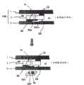
图3示出了一种状态,其中由于主体100旋转时产生的离心力、流体(未示出)自身的液压力以及由热产生装置产生的热,孔封闭膜13a破裂使得孔10被打开并且存储在腔室20中的流体移到腔室21中。图4和图5是示出根据本发明构思当前实施例的薄膜阀器件的操作状态的截面图。附图标记1、2和3表示构成主体100的基板。主体100可以包括上基板1、中间基板2和下基板3。当通过注射成型形成上基板1、中间基板2和下基板3时,可以形成作为流动路径的通道22、作为缓冲贮液器的腔室20和22以及连接通道22的孔10。上基板1、中间基板2和下基板3被结合在一起以形成单一主体100。3 shows a state in which the
图4示出了孔10被热收缩塞70a塞上从而阻挡通道22的状态。图5示出了热收缩塞70a由于从热产生装置产生的热而收缩使得孔10被打开的状态。在该情形下,相邻的腔室20和21可以通过通道22互连。此外,在根据本发明构思当前实施例的薄膜阀器件中,由于形成在主体100中的通道22是窄的,所以通风孔12形成在上基板1中以允许流体不受阻力地平稳地流过通道22。此外,可以形成限制凹槽101a以在孔10被打开时限制热收缩塞70a被推动而接触下基板3。限制凹槽101a可以向热收缩塞70a提供可移动的空间以防止已经被打开的孔10被热收缩塞70a封闭。FIG. 4 shows a state where the
在本发明构思的当前实施例中,限制凹槽101a可以具有比已经收缩的热收缩塞70a的直径大20%-70%的直径。In the current embodiment of the present inventive concept, the
在本发明构思的当前实施例中,限制凹槽101a还可以包括沿限制凹槽101a的边缘(rim)的压力钳(pressure jaw)102a,压力钳102a的直径小于没有收缩的热收缩塞70a的原始直径。当装配主体100时,热收缩塞70a由于形成在下基板3中的压力钳102a而被推到外部孔10a中,使得热收缩塞70a封闭孔10a。附图标记10表示热收缩塞70a和中间基板2彼此接触的区域。这个接触区域被成形为对应于热收缩塞70a的形状,从而在孔10被封闭时防止流体泄露。因而,在制造薄膜阀器件的工艺中,当施加外部压力时,孔10能够由于压力钳102而被封闭。In the current embodiment of the present inventive concept, the
附图标记10a表示在热收缩塞70a与中间基板2之间的接触区域的外边界(外部孔),附图标记10b表示接触区域的内边界(“内部孔”)。当外部孔10b与热收缩塞70a之间的接触区域更大时,更可能防止流体泄露。随着外部孔10b和内部孔10a的直径之间的差异越大,热收缩塞70a与中间基板2之间的接触区域变大,从而能够防止流体泄露。
在本发明构思的另一实施例中,热收缩塞70a可以具有0.1mm至5mm的直径以及0.5mm至2mm的厚度。此外,为了在热收缩塞70a封闭孔10时增强热收缩塞70a的密封能力,热收缩塞70a可以涂覆有粘合剂。In another embodiment of the present inventive concept, the
图6至图8示出了根据本发明构思实施例的薄膜阀器件,其使用非磁性塞70b。附图标记1、2和3分别表示形成主体100的上基板、中间基板和下基板。图8是非磁性塞70b或磁性塞70c的详细视图。根据由附图标记81表示的元件的材料,在图8中示出的塞可以是非磁性塞70b或磁性塞70c。非磁性塞70b或磁性塞70c的表面可以涂覆有粘合剂80。涂覆有粘合剂80的表面可以接触中间基板20中的孔10以封闭孔10。粘合剂80可以是热塑性粘合剂。图6示出了当孔10被非磁性塞70b封闭时通道22被阻挡的状态。图7示出了当非磁性塞70b由于热产生装置产生的热和主体100旋转时产生的离心力而与孔10分离时孔10被打开的状态。在该情形下,相邻的腔室20和21可以通过通道22互连。此外,限定凹槽101b可以形成在下基板3中以当孔10被打开时将非磁性塞70b稳定地限定在下基板3中。限定凹槽101b可以防止与孔10分离的非磁性塞70b远离孔自由地移动。在本发明构思的当前实施例中,限定凹槽101b的直径可以比非磁性塞70b的直径大20%-70%。非磁性元件或磁性元件81可以是圆柱形薄膜或环形(donut-shaped)薄膜形式的金属材料。6 to 8 illustrate a thin film valve device using a
图8是非磁性塞70b或磁性塞70c的详细视图。图8示出了非磁性塞70b或磁性塞70c的实施例,其包括环形薄膜形式的金属元件。对于包括环形薄膜形式的金属元件的磁性塞70c,激光束可以穿过金属元件的环形孔82照射,使得磁性塞70能够被保护而不被激光束去磁。FIG. 8 is a detailed view of the
在根据本发明构思当前实施例的薄膜阀器件中,磁性元件81可以由磁性材料形成,该磁性材料的居里点(居里温度)远高于粘合剂80的软化点。In the thin film valve device according to the present embodiment of the inventive concept, the
图9至图11示出了根据本发明构思实施例的薄膜阀器件,其使用磁性塞70c。附图标记1、2和3分别表示形成主体100的上基板、中间基板和下基板。磁性塞70c在图8中详细地示出。磁性元件81可以是圆柱形薄膜或环形薄膜形式的金属材料或永磁体。9 to 11 illustrate a thin film valve device using a
图9示出了根据本发明构思实施例的薄膜阀器件,其中通道22和孔10形成在薄膜阀器件的主体100中的相邻腔室20与21之间。在图9中,还示出了孔10被磁性塞70c封闭,以及通过使用由热产生装置107产生的热然后使用位于主体100下方的永磁体5a来弱化磁性塞70的粘接强度而打开孔20,使得相邻腔室20和22的通道22互连。图9中的上图示出了当孔10被磁性塞70c封闭时通道22被阻挡。图9中的下图示出当磁性塞70c由于(i)离心力以及热产生装置产生的热,(ii)由热产生装置107产生的热以及在永磁体5a和磁性塞70c之间的吸引力,或(iii)由热产生装置107产生的热、离心力以及永磁体5a与磁性塞70c之间的吸引力而使磁性塞70c与孔10分离时,孔10被打开。在该情形下,相邻腔室20和21可以通过通道22互连。FIG. 9 illustrates a thin film valve device according to an embodiment of the inventive concept, wherein a
在根据本发明构思当前实施例的薄膜阀器件中,永磁体5a和热产生装置107可以安装在可移动的滑块(slider)211上,使得永磁体5a和热产生装置107能够在空间上朝向孔10移动。In the thin film valve device according to the present embodiment of the present inventive concept, the
图10示出了根据本发明构思实施例的薄膜阀器件,其具有可逆的打开/封闭功能。FIG. 10 illustrates a membrane valve device having a reversible opening/closing function according to an embodiment of the inventive concept.
在图10的薄膜阀器件中,通道22和孔10形成在薄膜阀器件的主体100中的相邻通道20和21之间。图10的薄膜阀器件的可逆的打开/封闭功能包括:使用磁性塞70c封闭孔10;通过使用由热产生装置107产生的热以及然后使用位于主体100下方的永磁体5a弱化磁性塞70的粘接强度而打开孔10,使得相邻腔室20和22的通道22互连;以及通过使用由热产生装置107产生的热恢复磁性塞70c的粘接强度然后通过移动永磁体5c远离孔10的中心,使得设置在主体100的上部上的永磁体4a(在下文中,称为上永磁体4a)吸引磁性塞70c而再次封闭孔10。In the membrane valve device of Fig. 10, the
从图10上部数的第一个图示出了当孔10被磁性塞70c封闭时通道22被阻挡。从图10上部数的第二个图示出了由于(i)离心力以及热产生装置产生的热,(ii)由热产生装置107产生的热以及在永磁体5a和磁性塞70c之间的吸引力,或(iii)由热产生装置107产生的热、离心力以及永磁体5a与磁性塞70c之间的吸引力而使得磁性塞70c与孔10分离时,孔10打开。在该情形下,相邻腔室20和21可以通过通道22互连。从图10的上部数的第三图示出了由于由热产生装置107产生的热以及上永磁体4a与磁性塞70c之间的吸引力而使得孔10被磁性塞70c再次封闭。换言之,一旦粘性剂80的粘接强度由于从热产生装置107产生的热而恢复,则关闭热产生装置107并使滑块211远离孔10的中心移动,使得上永磁体4a能够吸引磁性塞70c以通过施加在上永磁体4a与磁性塞70c之间的吸引力而封闭孔10。然后,随着粘合剂80硬化,磁性塞70c紧密地封闭孔10。The first figure from the top of Figure 10 shows that the
图11示出了根据本发明构思另一实施例的薄膜阀器件,其具有可逆的打开/封闭功能。在图11的薄膜阀器件中,通道22和孔10形成在薄膜阀器件的主体100中的相邻腔室20与21之间。孔10可以在循环期间被磁性塞70c封闭。当使用薄膜阀器件时,通过使用由热产生装置107产生的热来弱化磁性塞70的粘接强度然后使用位于主体100下方的永磁体5a,可以打开孔20,使得相邻腔室20和22的通道22互连。通过远离孔10的中心移动永磁体5a使得设置在主体100的上部分上的永磁体4a能够吸引磁性塞70c,孔10可以被再次封闭。孔10能够由于上永磁体4a与磁性塞70c之间的吸引力而被再次封闭。通过使位于主体100下方的永磁体5a朝向孔10的中心移动,孔10可以被再次打开。薄膜阀器件的可逆的打开/封闭功能如上所述。换言之,当自从循环期间第一次打开孔10时,使用由热产生装置107产生的热以及磁性塞70c与下永磁体5a之间的吸引力。然而,一旦已经第一次打开孔10,则可以仅使用磁性塞70c与上永磁体4a或者下永磁体5a之间的吸引力而再次打开孔10,而不需要热产生装置107的帮助。孔10需要被粘合剂紧密地密封以防止循环期间在腔室中存储的流体蒸发。为了第一次打开具有被紧密地密封的孔10的薄膜阀器件,可能需要从热产生装置107产生的热。FIG. 11 illustrates a membrane valve device having a reversible opening/closing function according to another embodiment of the present inventive concept. In the membrane valve device of Fig. 11, the
从图11的上部数的第一图示出了在循环期间当孔10被磁性塞70c封闭时通道22被阻挡。从图10的上部数的第二图示出当磁性塞70c由于(i)离心力以及热产生装置产生的热,(ii)由热产生装置107产生的热、离心力以及在永磁体5a和磁性塞70c之间的吸引力,或(iii)由热产生装置107产生的热、离心力以及永磁体5a与磁性塞70c之间的吸引力而与孔10分离时,孔10被第一次打开。在该情形下,相邻腔室20和21可以通过通道22互连。从图11的上部数的第三图示出了孔10由于上永磁体4a与磁性塞70c之间的吸引力而被磁性塞70c再次封闭。从图11的上部数的第四图示出了当磁性塞70c由于下永磁体5a与磁性塞70c之间的吸引力而与孔10分离时孔10被再次打开。在下文中,薄膜阀器件的可逆的打开和封闭操作如图11的第三图和第四图所示。The first figure from the top of Fig. 11 shows that the
为了封闭孔10以阻挡通道22,如图11的第三图所示,下永磁体5a远离孔10的中心移动,使得磁性塞70c能够由于上永磁体4a的磁力而被向上吸引并封闭孔10。换言之,孔10可以由于在上永磁体4a与磁性塞70c之间施加的吸引力而被封闭。同时,为了打开孔10,如图11的第二图和第四图所示,下永磁体5a朝向孔10的中心移动,使得磁性塞70c能够被永磁体5a向下吸引。换言之,当下永磁体5a与磁性塞70c之间的吸引力变得比上永磁体4a与磁性塞70c之间的吸引力强时,孔10能够被打开。这可以通过降下永磁体5a设计为具有比上永磁体4a强的磁力或者通过将下永磁体5a设置得比上永磁体4a更靠近磁性塞70c而实现。In order to close the
参照图9至图11,限制凹槽101c可以形成在下基板3中以当孔10被打开时将磁性塞70c稳定地限制在下基板3中。限制凹槽101c可以防止与孔10分离的磁性塞70c远离孔自由地移动。在本发明构思的当前实施例中,限制凹槽101c的直径可以比磁性塞70c的直径大20%-200%。Referring to FIGS. 9 to 11 , a restricting
图12和图16示出了根据本发明构思当前实施例的使用珠(球)塞的薄膜阀器件。12 and 16 illustrate a thin film valve device using a bead (ball) plug according to the current embodiment of the inventive concept.
具体地,图12和图13示出了使用圆柱形珠(球)塞的薄膜阀器件,图14至图16示出了使用球形珠(球)塞的薄膜阀器件。主体100可以包括上基板1、中间基板2和下基板3。当通过注射成型形成上基板1、中间基板2和下基板3时,可以形成作为流动路径的通道22、作为缓冲贮液器的腔室20和22以及连接通道22的孔10。上基板1、中间基板2和下基板3被结合在一起以形成薄膜阀器件的单一主体100。孔10在循环期间被插在孔10附近的珠(球)塞60完全封闭。此外,当使用薄膜阀器件时,珠(球)塞60由于离心力和从热产生装置产生的热而朝向辅助通道23移动,使得孔10被打开。Specifically, FIGS. 12 and 13 show a thin film valve device using a cylindrical bead (ball) plug, and FIGS. 14 to 16 show a thin film valve device using a spherical bead (ball) plug. The
图13示出了图12的薄膜阀器件的操作。FIG. 13 illustrates the operation of the membrane valve device of FIG. 12 .
图13中的左图示出了当孔10被珠(球)塞60封闭时通道22被阻挡的状态。图13中的右图示出了当珠(球)塞60由于主体100旋转时产生的离心力以及由热产生装置产生的热而与孔10分离时孔10被打开的状态。The left diagram in FIG. 13 shows a state where the
图14和图15示出了根据本发明构思实施例的薄膜阀器件,其使用球形珠(球)塞60。在孔10被珠(球)塞封闭的状态下,珠(球)塞60与孔10分离然后由于离心力以及从热产生装置产生的热而朝向辅助通道23移动。在该情形下,为了使珠(球)塞60易于从孔10分离,与珠(球)塞60的曲率一致的珠(球)通道10c可以形成在辅助通道23中。辅助通道23和珠(球)通道10c可以用于容纳或移动与孔10分离的珠(球)塞60。图14和图15中的左图示出了当孔10被珠(球)塞60封闭时通道22被阻挡的状态。图14和图15中的右图示出了当珠(球)塞60由于主体100旋转时产生的离心力以及从热产生装置产生的热而与孔10分离并朝向辅助通道23移动时孔10被打开的状态。14 and 15 illustrate a thin film valve device using a spherical bead (ball) plug 60 according to an embodiment of the inventive concept. In a state where the
图16示出了珠(球)通道10c。附图标记10a表示在珠(球)塞60与中间基板2之间的接触区域的外边界(“外部孔”),附图标记10b表示接触区域的内边界(“内部孔”)。随着外部孔10a和内部孔10b的直径之间的差异变大,珠(球)塞60与中间基板2之间的接触区域变大,从而能够防止流体泄露。附图标记61a表示涂覆在珠(球)61b上的粘合剂。Figure 16 shows a bead (ball)
在根据本发明构思当前实施例的薄膜阀器件中,用于薄膜阀器件的粘合剂可以是热塑性粘合剂,用于结合基板的薄膜胶带层可以是热固性粘合剂。在该情形下,薄膜阀上的热塑性粘合剂很可能由于从热产生装置产生的热而易于软化,其粘接强度变弱,而其相邻的部分和其余基板结合部分被热固性粘合剂结合,因而它们的粘接强度不会由于从热产生装置产生的热而变弱。In the thin film valve device according to the current embodiment of the inventive concept, the adhesive for the thin film valve device may be a thermoplastic adhesive, and the thin film tape layer for bonding the substrate may be a thermosetting adhesive. In this case, the thermoplastic adhesive on the film valve is likely to be easily softened due to the heat generated from the heat generating device, and its bonding strength becomes weak, while its adjacent portion and the remaining substrate bonding portion are replaced by the thermosetting adhesive. bonded so that their bonding strength is not weakened by the heat generated from the heat generating means.
在根据本发明构思当前实施例的薄膜阀器件中,热塑性粘合剂(胶带)可以是热熔性粘合剂,热固性粘合剂(胶带)可以是丙烯酸粘合剂。In the thin film valve device according to the current embodiment of the inventive concept, the thermoplastic adhesive (tape) may be a hot melt adhesive, and the thermosetting adhesive (tape) may be an acrylic adhesive.
在根据本发明构思当前实施例的薄膜阀器件中,热固性胶带(粘合剂)可以具有120度或更高的软化温度,热塑性胶带(粘合剂)可以具有60至80度的软化温度。薄膜阀上的粘合剂是热塑性粘合剂,基板的基板结合部分形成为包含热固性粘合剂的薄膜胶带层。因而,薄膜阀被预加热至等于或高于热塑性粘合剂的软化温度的温度,然后接触中间基板2中的孔10。然后,上基板1和下基板3结合在一起。由于热固性胶带的软化点高于热塑性胶带的软化点,所以可以对基板的形成为热固性胶带的部分进行结合,而不考虑加热。In the thin film valve device according to the current embodiment of the inventive concept, the thermosetting tape (adhesive) may have a softening temperature of 120 degrees or more, and the thermoplastic tape (adhesive) may have a softening temperature of 60 to 80 degrees. The adhesive on the membrane valve is a thermoplastic adhesive and the substrate bonding portion of the substrate is formed as a layer of membrane tape containing a thermosetting adhesive. Thus, the membrane valve is preheated to a temperature equal to or higher than the softening temperature of the thermoplastic adhesive, and then contacts the
图17至图20示出了薄膜阀控制装置的实施例,其用于控制上述根据本发明构思的一个实施例的薄膜阀器件的操作。17 to 20 illustrate an embodiment of a membrane valve control device for controlling the operation of the above-described membrane valve device according to an embodiment of the present inventive concept.
图17示出了本发明构思的实施例,其中激光束产生装置用作热产生装置。FIG. 17 shows an embodiment of the present inventive concept in which a laser beam generating device is used as a heat generating device.
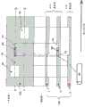
图17示出了用于控制薄膜阀器件100的薄膜阀控制装置100a的实施例,腔室、通道和薄膜阀集成在薄膜阀器件100中,其中腔室储存用于化验的各种缓冲溶液并用作各种化学反应的空间,通道是流体和缓冲溶液的流动路径,薄膜阀打开和关闭通道和孔。薄膜阀控制装置100a控制薄膜阀器件100的旋转以及永磁体5a和激光束产生装置107的空间移动以选择性地打开和关闭多个薄膜阀。附图标记100表示薄膜阀器件的主体,其通过依次层叠上基板1、中间基板2和下基板3而形成。当通过注射成型形成上基板1、中间基板2和下基板3时,形成作为流动路径的通道、作为缓冲贮液器的腔室以及连接通道的多个孔。上基板1、中间基板2和下基板3被结合在一起以形成单一主体100。腔室130、131、132、133、140、141、142和143的阀操作可以通过薄膜阀V1、V2、V3、V4、V5、V6和V7来进行,其中在上述的其它类型的薄膜阀中薄膜阀V1、V2、V3、V4、V5、V6和V7使用图11的磁性塞70c。薄膜阀V1、V2、V3、V4、V5、V6和V7可以被分别地控制以通过上永磁体4a、4b和4c以及可移动永磁体5a的磁力打开或关闭。附图标记120表示样品注入元件,诸如分配器、吸液管(pipette)、注射器(syringe)或柳叶刀(lancet)。附图标记121表示样品注入孔,附图标记170表示圆盘孔。附图标记130表示用于由将被化验的化验材料(生物材料)制备样品的制备室,附图标记131表示用于扩增样品、稀释或混合样品或者标注样品的缓冲室,附图标记132表示用于生物、化学或生物化学反应的腔室,其是化验场所(site),在该化验场所处用于化验缓冲室中的样品的捕获探针通过固定元件附着到或固定在基板上,附图标记133表示用于收集由清洗工艺产生的废弃物(waste)的废料室。捕获探针可以被附着或固定成阵列以从单个化验材料或样品检测多个分析物。DNA芯片、蛋白质芯片、多孔膜(porous membrane)或96孔板可以集成在化验场所132中。多孔膜的示例包括引起样品扩散的硝化纤维(NC)膜、尼龙膜或碳纳米管。96孔板、384孔板或1536孔板可以用于生物化学和分子生物化验以筛选新的药物或材料。制备室130可以用于从血液提取DNA,以在主体100高速旋转时通过离心分离而从血液提取血清或血浆,或者从农产品提取农药、细菌或重金属成分。扩增工艺(amplification process)可以包括扩增DNA的聚合酶链反应(PCR)工艺或在富集培养基(enrichment culture medium)中繁殖细菌的工艺。附图标记140、141、142和143可以储存用于从化验材料提取样品的萃取溶液、包括用于扩增工艺的聚合酶和引物(primer)的酶、用于杂交的酶、用于稀释样品的稀释溶液、标记材料和用于生物化学反应的生物化学材料、清洗溶液等。附图标记102表示用于旋转薄膜阀器件100的主轴马达。附图标记211表示安装有可移动的永磁体和激光束产生装置107的滑块,可移动的永磁体和激光束产生装置107的操作可以通过滑块马达109以及蜗轮连接单元109a和109b来控制。在每个工艺(制备工艺、扩增工艺、混合工艺、稀释工艺、标记工艺、生物、化学或生物化学反应工艺或清洗工艺)的起点和终点,薄膜阀的打开和关闭可以由于安装在滑块211上的永磁体5a和激光束产生装置107相对于相应的薄膜阀的空间移动以及由于主体100旋转时产生的离心力而被控制。Fig. 17 shows an embodiment of a membrane
根据本发明构思的另一实施例,当打开或关闭薄膜阀时,可以先进行相对于薄膜阀沿径向和方位角方向的空间移动(空间寻址)。空间寻址(spatialaddressing)包括相对于薄膜阀的径向和方位角寻址(azimuthal addressing)。According to another embodiment of the inventive concept, when opening or closing the membrane valve, spatial movement in radial and azimuthal directions relative to the membrane valve may be performed first (spatial addressing). Spatial addressing (spatial addressing) includes radial and azimuthal addressing (azimuthal addressing) relative to the membrane valve.
相对于薄膜阀沿径向方向的空间移动可以通过滑块马达109执行,滑块马达109沿径向方向双向地移动滑块。滑块211可以通过滑块马达109沿径向方向从主体100的中心向外移动或者从外部向主体100的中心移动。The spatial movement in the radial direction relative to the membrane valve can be performed by a
根据本发明构思的另一实施例,一旦完成沿径向方向的空间移动,通过将从激光束产生装置107输出的脉冲束或连续束辐射到旋转主体100上,可以执行相对于薄膜阀沿方位角方向的空间移动。在激光束产生装置107在相应的薄膜阀的方位位置被周期性地打开时,可以产生脉冲束,其中方位位置基于由方位角检测器99获得的参考触发信号来计算。参考触发信号表示主体100的参考方位角。According to another embodiment of the inventive concept, once the spatial movement in the radial direction is completed, by irradiating the pulsed beam or continuous beam output from the laser
根据本发明构思的另一实施例,脉冲束或连续束的温度可以类似于热塑性粘合剂的软化温度。脉冲束或连续束可以加热用于结合基板的粘合剂以及在孔周围的粘合剂,并弱化粘合剂的粘接强度。然而,实际上,由于热固性粘合剂的软化温度高于孔周围的热塑性粘合剂的软化温度,所以脉冲束或连续束不太可能弱化结合基板的热固性粘合剂的粘接强度。According to another embodiment of the inventive concept, the temperature of the pulsed beam or the continuous beam may be similar to the softening temperature of a thermoplastic adhesive. The pulsed or continuous beam can heat the adhesive used to bond the substrates and the adhesive around the holes and weaken the bond strength of the adhesive. In practice, however, pulsed or continuous beams are less likely to weaken the bond strength of the thermoset adhesive bonded to the substrate since the softening temperature of the thermoset adhesive is higher than that of the thermoplastic adhesive surrounding the hole.
根据本发明构思的另一实施例,方位角检测器99可以实施为光耦合器。According to another embodiment of the inventive concept, the
根据本发明构思的另一实施例,方位角检测器99可以是反射或透射光检测器。According to another embodiment of the inventive concept, the
根据本发明构思的另一实施例,当用于打开或关闭薄膜阀的激光束产生装置107和永磁体5a安装在滑块211上时,滑块211沿径向和方位方向空间地移动以选择性地(单独地)或独立地控制多个薄膜阀的打开和关闭。According to another embodiment of the inventive concept, when the laser
根据本发明构思的另一实施例,永磁体5a可以通过上/下移动控制元件103而向上和向下移动,从而控制主体100与永磁体5a之间的间隙。上/下移动控制元件103可以通过控制齿轮的旋转和流经电磁体的电流量来控制永磁体5a向上和向下移动。附图标记110b表示柔性电缆,用于传输安装在滑块211上的上/下移动控制元件103和激光束产生装置107需要的各种控制信号。柔性电缆110b可以通过针座(wafer)或束(harness)110a连接到中央控制单元101。附图标记181表示其上将放置薄膜阀器件100的转盘。薄膜阀器件100能够通过圆盘孔(disc aperture)170前装载(front-loaded)或顶装载(top-loaded)在转盘181上。附图标记188表示具有内置存储器的无线射频集成电路(RFIC),其可以包括用于薄膜阀器件100的协议、化验算法、参考控制值、化验场所的位置信息、生物信息学信息和自诊断相关的信息。此外,可以存储薄膜阀器件的个人加密信息和ID信息以防止未经授权的使用。无线RFIC 188可以是智能IC卡。存储在无线RFIC 188中的信息可以被无线地提供到中央控制单元101,并可以用于加密(encrypt)个人数据。附图标记110表示用于供应电力到无线RFIC 188的射频产生单元。根据弗莱明法则,当无线RFIC 188中的感应线圈响应由射频产生单元110产生的波时,产生足够量的电,并且该足够量的电可以被供应到无线RFIC 188。According to another embodiment of the present inventive concept, the
根据本发明构思的另一实施例,薄膜阀控制装置还可以包括供应电力到无线RFIC 188的太阳能电池189。According to another embodiment of the present inventive concept, the thin film valve control device may further include a
根据本发明构思的另一实施例,薄膜阀控制装置还可以包括用于供应光能到薄膜阀器件100中的太阳能电池189的照明单元108。照明单元108可以包括灯或集成有多个高亮度LED的高亮度发光二极管(LED)模块。According to another embodiment of the inventive concept, the membrane valve control device may further include a
根据本发明构思的另一实施例,当薄膜阀器件100装载到薄膜阀控制装置100a上时,薄膜阀器件100的ID可以通过无线RFIC 188被无线地传输到中央控制单元101,使得中央控制单元101能够将当前装载的圆盘识别为薄膜阀器件。According to another embodiment of the present invention concept, when the
根据本发明构思的另一实施例,薄膜阀控制装置还可以包括输入/输出单元111。According to another embodiment of the present inventive concept, the membrane valve control device may further include an input/
根据本发明构思的另一实施例,输入/输出器件111可以遵守通用串行总线(USB)、IEEE1394、ATAPI、SCSI、IDE或有线/无线互联网连接的通信标准。According to another embodiment of the inventive concept, the input/
图18示出了光检测器99的实施例。如果光检测器99是透射式光检测器,则光检测器99可以在旋转主体100的参考孔98a经过光耦合器99a和99b之间时产生参考触发信号,并将参考触发信号提供到中央控制单元101。如果光检测器99是反射式光检测器,则当旋转主体100上的参考反射器98b经过光耦合器99a和99b上方时,光检测器99可以产生参考触发信号,并将该参考触发信号提供到中央控制单元101。仅当特定的薄膜阀对应于激光束产生装置100设置使得在主体100旋转时相应的薄膜阀被选择性地加热时,中央控制单元101可以与参考触发信号同步地开启激光束产生装置107。FIG. 18 shows an embodiment of a
图19示出了滑块211的实施例,激光束产生装置107、永磁体5a和上/下移动控制元件103安装在滑块211上。滑块211的移动可以由涡轮连接单元109a和109a来控制,涡轮连接单元109a和109a连接到滑块马达109的轴(shaft)。滑块211能够利用滑动臂108a和108b作为引导(guide)而平稳地移动。滑动臂108a和108b可以通过螺钉110a、110b、110c和110d耦接到薄膜阀控制装置100a的主体。附图标记100b表示柔性电缆,其能够通过与针座或束110a的连接而连接到中央控制单元101。附图标记181表示被主轴马达102旋转的转盘。FIG. 19 shows an embodiment of a
图20示出了薄膜阀控制装置100a的实施例,用于控制如上所述的根据本发明构思的一个实施例的薄膜阀器件的薄膜阀的打开和关闭。附图标记300表示支撑薄膜阀控制装置100a的主体。电路板140(其形成薄膜阀控制装置100a的底部)结合到薄膜阀控制装置100a的主体300。用于控制薄膜阀控制装置1001的中央控制单元101、射频产生单元110、照明单元108以及输入/输出单元111可以布置在电路板140上。中央控制单元101可以控制主轴马达102以旋转或停止薄膜阀器件100,可以控制滑块马达109以空间地移动激光束产生装置107,并可以在薄膜阀位于方位角位置时控制激光束产生装置107以周期性地输出脉冲束,其中该方位角位置基于由方位角检测器99获得的参考触发信号而计算。FIG. 20 shows an embodiment of a membrane
根据本发明构思的另一实施例,中央控制单元101还可以包括声音合成元件,以根据装载在薄膜阀控制装置100a上的薄膜阀器件的类型而向用户提供用户指南和每个工艺的额外解释。附图标记104表示压缩装载在圆盘孔周围的薄膜阀器件100的压缩元件。压缩元件104可以被设计成对转盘181施加磁性吸引力的空闲转盘,使得薄膜阀器件100能够由于该磁性吸引力而被压缩,并允许薄膜阀器件100的垂直移动和空转。According to another embodiment of the present inventive concept, the
Claims (48)
Translated fromChineseApplications Claiming Priority (3)
| Application Number | Priority Date | Filing Date | Title |
|---|---|---|---|
| KR20070120586 | 2007-11-22 | ||
| KR10-2007-0120586 | 2007-11-22 | ||
| PCT/KR2008/006631WO2009066897A2 (en) | 2007-11-22 | 2008-11-11 | Thin film valve device and its controlling apparatus |
Publications (2)
| Publication Number | Publication Date |
|---|---|
| CN101873885A CN101873885A (en) | 2010-10-27 |
| CN101873885Btrue CN101873885B (en) | 2013-07-31 |
Family
ID=40667964
Family Applications (1)
| Application Number | Title | Priority Date | Filing Date |
|---|---|---|---|
| CN2008801175186AExpired - Fee RelatedCN101873885B (en) | 2007-11-22 | 2008-11-11 | Thin film valve device and its controlling apparatus |
Country Status (6)
| Country | Link |
|---|---|
| US (1) | US8658113B2 (en) |
| EP (1) | EP2214801A4 (en) |
| JP (1) | JP2011505548A (en) |
| KR (1) | KR20110073381A (en) |
| CN (1) | CN101873885B (en) |
| WO (1) | WO2009066897A2 (en) |
Families Citing this family (23)
| Publication number | Priority date | Publication date | Assignee | Title |
|---|---|---|---|---|
| ES2842969T3 (en)* | 2008-01-21 | 2021-07-15 | Nexus Dx Inc | Thin film layer centrifuge device and analysis method using the same |
| JP2011155921A (en)* | 2010-02-02 | 2011-08-18 | Seiko Epson Corp | Biochip, specimen reactor, and method for specimen reaction |
| US20110312078A1 (en) | 2010-06-17 | 2011-12-22 | Geneasys Pty Ltd | Microfluidic device for detecting target nucleic acid sequences in mitochondrial dna |
| KR101439483B1 (en) | 2012-12-05 | 2014-09-15 | 매쓰파워 주식회사 | A thin film valve apparatus using a hole closing membrane |
| US9857370B2 (en) | 2013-07-22 | 2018-01-02 | National Technology & Engineering Solutions Of Sandia, Llc | Amplification of biological targets via on-chip culture for biosensing |
| JP6662776B2 (en)* | 2013-08-12 | 2020-03-11 | コーニンクレッカ フィリップス エヌ ヴェKoninklijke Philips N.V. | Microfluidic device using valve |
| DE102014117976B4 (en)* | 2014-12-05 | 2018-10-11 | Biflow Systems Gmbh | Fluidic device and method of operating the same |
| EP3245283B1 (en)* | 2015-01-16 | 2020-09-23 | The Regents of The University of California | Led driven plasmonic heating apparatus for nucleic acids amplification |
| KR101530935B1 (en)* | 2015-01-26 | 2015-06-25 | 한양대학교 산학협력단 | Valve for Porous Materials |
| US10737261B1 (en)* | 2016-09-29 | 2020-08-11 | Triad National Security, Llc | Reversibly bonded devices and methods of making and using the same |
| JP6421159B2 (en)* | 2016-10-28 | 2018-11-07 | シスメックス株式会社 | Liquid sealed cartridge and liquid feeding method |
| WO2018173390A1 (en)* | 2017-03-21 | 2018-09-27 | ソニー株式会社 | Microwell-sealing cover plate and microchip |
| KR102182239B1 (en)* | 2017-12-15 | 2020-11-25 | 프리시젼바이오 주식회사 | Diagnostic Cartridge |
| KR20200009859A (en)* | 2018-07-20 | 2020-01-30 | 재단법인대구경북과학기술원 | An apparatus to control centrifugal valves |
| JP7448908B2 (en) | 2019-05-31 | 2024-03-13 | ゴビ テクノロジーズ インコーポレイテッド | thermal regulation system |
| US11236846B1 (en)* | 2019-07-11 | 2022-02-01 | Facebook Technologies, Llc | Fluidic control: using exhaust as a control mechanism |
| JP7445403B2 (en) | 2019-09-27 | 2024-03-07 | シスメックス株式会社 | Liquid sealed cartridge and liquid delivery method |
| CN112452362B (en)* | 2020-09-25 | 2021-09-21 | 中山大学 | Pump-free fixed zebra fish microfluidic chip system and preparation method and application thereof |
| KR102331145B1 (en)* | 2020-11-12 | 2021-12-01 | 주식회사 파라텍 | Fire extinguishing device for battery module of magnetic holder type |
| KR102639815B1 (en)* | 2021-06-01 | 2024-02-23 | 김박미 | Fire extinguisher with improved function |
| WO2023019447A1 (en)* | 2021-08-17 | 2023-02-23 | 京东方科技集团股份有限公司 | Control valve structure and usage method therefor, microfluidic chip, and nucleic acid extraction device |
| CN114768895A (en)* | 2022-03-12 | 2022-07-22 | 北京化工大学 | A laser bonding method suitable for thermoplastic polymer material microfluidic chips |
| KR102505026B1 (en)* | 2022-07-11 | 2023-02-28 | 성균관대학교산학협력단 | Pcr disc apparatus using micro-needle tunnelling channel and analysis method using the same |
Citations (3)
| Publication number | Priority date | Publication date | Assignee | Title |
|---|---|---|---|---|
| WO2003080868A1 (en)* | 2002-03-27 | 2003-10-02 | Jae-Chern Yoo | Bio-disc, bio-driver apparatus, and assay method using the same |
| US6869671B1 (en)* | 2002-06-03 | 2005-03-22 | University Of Notre Dame | Enabling nanostructured materials via multilayer thin film precursor and applications to biosensors |
| CN1666103A (en)* | 2002-07-05 | 2005-09-07 | 奥麦迪可斯株式会社 | Device for quantitative analysis of biological materials |
Family Cites Families (21)
| Publication number | Priority date | Publication date | Assignee | Title |
|---|---|---|---|---|
| US20010055812A1 (en)* | 1995-12-05 | 2001-12-27 | Alec Mian | Devices and method for using centripetal acceleration to drive fluid movement in a microfluidics system with on-board informatics |
| JP3469585B2 (en)* | 1997-05-23 | 2003-11-25 | ガメラ バイオサイエンス コーポレイション | Apparatus and method for using centripetal acceleration to drive flow motion in microfluidics systems |
| AU739563B2 (en)* | 1998-03-11 | 2001-10-18 | Boehringer Ingelheim Microparts Gmbh | Sample support |
| GB9808836D0 (en)* | 1998-04-27 | 1998-06-24 | Amersham Pharm Biotech Uk Ltd | Microfabricated apparatus for cell based assays |
| WO2001087486A2 (en)* | 2000-05-15 | 2001-11-22 | Tecan Trading Ag | Microfluidics devices and methods for performing cell based assays |
| JP4773035B2 (en)* | 2000-06-28 | 2011-09-14 | スリーエム イノベイティブ プロパティズ カンパニー | Enhanced sample processing apparatus, system and method |
| DK200100281A (en)* | 2001-02-21 | 2002-08-22 | Flowcon Int As | Diaphragm valve with regulator |
| US20020155010A1 (en)* | 2001-04-24 | 2002-10-24 | Karp Christoph D. | Microfluidic valve with partially restrained element |
| KR100552078B1 (en)* | 2001-05-31 | 2006-02-20 | 유재천 | Micro valve device using micro bead and its control method |
| US6919058B2 (en)* | 2001-08-28 | 2005-07-19 | Gyros Ab | Retaining microfluidic microcavity and other microfluidic structures |
| JP2003083965A (en)* | 2001-09-10 | 2003-03-19 | Adgene Co Ltd | Protein/nucleic acid analyzing chip |
| US20050026301A1 (en)* | 2002-03-25 | 2005-02-03 | Henry Petithory | Method and apparatus for controlling fluid movement in a microfluidic system |
| TW590982B (en)* | 2002-09-27 | 2004-06-11 | Agnitio Science & Technology I | Micro-fluid driving device |
| CN100380034C (en)* | 2002-12-04 | 2008-04-09 | 斯宾克斯公司 | Apparatus and method for programmable microscale manipulation of fluids |
| JP3927968B2 (en)* | 2003-06-13 | 2007-06-13 | キヤノン株式会社 | Fluid control mechanism |
| US7238269B2 (en)* | 2003-07-01 | 2007-07-03 | 3M Innovative Properties Company | Sample processing device with unvented channel |
| US7596073B2 (en)* | 2005-05-09 | 2009-09-29 | Searete Llc | Method and system for fluid mediated disk activation and deactivation |
| JP4940446B2 (en)* | 2005-06-28 | 2012-05-30 | サムスン エレクトロニクス カンパニー リミテッド | Biodrive device and analysis method using the same |
| US7527763B2 (en)* | 2005-07-05 | 2009-05-05 | 3M Innovative Properties Company | Valve control system for a rotating multiplex fluorescence detection device |
| JP2007170469A (en)* | 2005-12-20 | 2007-07-05 | Kawamura Inst Of Chem Res | Temperature responsive valve and its manufacturing method |
| KR101292536B1 (en)* | 2005-12-21 | 2013-08-07 | 삼성전자주식회사 | Bio memory disc and bio memory disc drive apparatus, and assay method using the same |
- 2008
- 2008-11-11CNCN2008801175186Apatent/CN101873885B/ennot_activeExpired - Fee Related
- 2008-11-11USUS12/743,933patent/US8658113B2/ennot_activeExpired - Fee Related
- 2008-11-11JPJP2010534879Apatent/JP2011505548A/enactivePending
- 2008-11-11KRKR1020107008024Apatent/KR20110073381A/ennot_activeAbandoned
- 2008-11-11EPEP08851751.1Apatent/EP2214801A4/ennot_activeWithdrawn
- 2008-11-11WOPCT/KR2008/006631patent/WO2009066897A2/enactiveApplication Filing
Patent Citations (3)
| Publication number | Priority date | Publication date | Assignee | Title |
|---|---|---|---|---|
| WO2003080868A1 (en)* | 2002-03-27 | 2003-10-02 | Jae-Chern Yoo | Bio-disc, bio-driver apparatus, and assay method using the same |
| US6869671B1 (en)* | 2002-06-03 | 2005-03-22 | University Of Notre Dame | Enabling nanostructured materials via multilayer thin film precursor and applications to biosensors |
| CN1666103A (en)* | 2002-07-05 | 2005-09-07 | 奥麦迪可斯株式会社 | Device for quantitative analysis of biological materials |
Also Published As
| Publication number | Publication date |
|---|---|
| JP2011505548A (en) | 2011-02-24 |
| WO2009066897A3 (en) | 2009-08-13 |
| EP2214801A2 (en) | 2010-08-11 |
| US8658113B2 (en) | 2014-02-25 |
| WO2009066897A2 (en) | 2009-05-28 |
| US20100243078A1 (en) | 2010-09-30 |
| KR20110073381A (en) | 2011-06-29 |
| EP2214801A4 (en) | 2016-12-21 |
| CN101873885A (en) | 2010-10-27 |
Similar Documents
| Publication | Publication Date | Title |
|---|---|---|
| CN101873885B (en) | Thin film valve device and its controlling apparatus | |
| US10682646B2 (en) | Thin film valve apparatus using a fluid hole closing membrane | |
| CN105378103B (en) | Nucleic Acid Amplification Disc Device Using Temperature-Sensitive Polymer Synthetic Body and Analysis Method Using It | |
| US7988915B2 (en) | Microfluidic device using microfluidic chip and microfluidic device using biomolecule microarray chip | |
| KR101555476B1 (en) | A thin film bio valve device and its controlling apparatus | |
| US7776267B2 (en) | Centrifugal force-based microfluidic device for protein detection and microfluidic system including the same | |
| US7635585B2 (en) | Micro valve apparatus using micro bead and method for controlling the same | |
| EP1905515A2 (en) | Centrifugal Force Based Microfluidic Device Having Thermal Activation Unit, Microfluidic System Including the Same and Method of Operating the Microfluidic System | |
| US8834812B2 (en) | Microfluidic device | |
| TWI758537B (en) | An injection molded microfluidic/fluidic cartridge integrated with silicon-based sensor | |
| US20110014094A1 (en) | Disk type microfluidic device and blood testing apparatus using the same | |
| US20120261026A1 (en) | Microfluidic device | |
| EP1885883A1 (en) | Bio-disc, bio-driver apparatus, and assay method using the same | |
| CN102004145A (en) | Disk type microfluidic device and blood testing apparatus using the same | |
| Mauk et al. | Microfluidic “Pouch” chips for immunoassays and nucleic acid amplification tests |
Legal Events
| Date | Code | Title | Description |
|---|---|---|---|
| C06 | Publication | ||
| PB01 | Publication | ||
| C10 | Entry into substantive examination | ||
| SE01 | Entry into force of request for substantive examination | ||
| C14 | Grant of patent or utility model | ||
| GR01 | Patent grant | ||
| CF01 | Termination of patent right due to non-payment of annual fee | Granted publication date:20130731 Termination date:20191111 | |
| CF01 | Termination of patent right due to non-payment of annual fee |