CN101873831A - Small-caliber laparoscopic surgical instrument - Google Patents
Small-caliber laparoscopic surgical instrumentDownload PDFInfo
- Publication number
- CN101873831A CN101873831ACN200880117758ACN200880117758ACN101873831ACN 101873831 ACN101873831 ACN 101873831ACN 200880117758 ACN200880117758 ACN 200880117758ACN 200880117758 ACN200880117758 ACN 200880117758ACN 101873831 ACN101873831 ACN 101873831A
- Authority
- CN
- China
- Prior art keywords
- pliers
- head
- driving
- flexible joint
- surgical apparatus
- Prior art date
- Legal status (The legal status is an assumption and is not a legal conclusion. Google has not performed a legal analysis and makes no representation as to the accuracy of the status listed.)
- Granted
Links
Images


Classifications
- A—HUMAN NECESSITIES
- A61—MEDICAL OR VETERINARY SCIENCE; HYGIENE
- A61B—DIAGNOSIS; SURGERY; IDENTIFICATION
- A61B34/00—Computer-aided surgery; Manipulators or robots specially adapted for use in surgery
- A61B34/70—Manipulators specially adapted for use in surgery
- A—HUMAN NECESSITIES
- A61—MEDICAL OR VETERINARY SCIENCE; HYGIENE
- A61B—DIAGNOSIS; SURGERY; IDENTIFICATION
- A61B17/00—Surgical instruments, devices or methods
- A—HUMAN NECESSITIES
- A61—MEDICAL OR VETERINARY SCIENCE; HYGIENE
- A61B—DIAGNOSIS; SURGERY; IDENTIFICATION
- A61B17/00—Surgical instruments, devices or methods
- A61B17/12—Surgical instruments, devices or methods for ligaturing or otherwise compressing tubular parts of the body, e.g. blood vessels or umbilical cord
- A—HUMAN NECESSITIES
- A61—MEDICAL OR VETERINARY SCIENCE; HYGIENE
- A61B—DIAGNOSIS; SURGERY; IDENTIFICATION
- A61B17/00—Surgical instruments, devices or methods
- A61B17/22—Implements for squeezing-off ulcers or the like on inner organs of the body; Implements for scraping-out cavities of body organs, e.g. bones; for invasive removal or destruction of calculus using mechanical vibrations; for removing obstructions in blood vessels, not otherwise provided for
- A—HUMAN NECESSITIES
- A61—MEDICAL OR VETERINARY SCIENCE; HYGIENE
- A61B—DIAGNOSIS; SURGERY; IDENTIFICATION
- A61B17/00—Surgical instruments, devices or methods
- A61B17/32—Surgical cutting instruments
- A—HUMAN NECESSITIES
- A61—MEDICAL OR VETERINARY SCIENCE; HYGIENE
- A61B—DIAGNOSIS; SURGERY; IDENTIFICATION
- A61B34/00—Computer-aided surgery; Manipulators or robots specially adapted for use in surgery
- A61B34/70—Manipulators specially adapted for use in surgery
- A61B34/71—Manipulators operated by drive cable mechanisms
- A—HUMAN NECESSITIES
- A61—MEDICAL OR VETERINARY SCIENCE; HYGIENE
- A61B—DIAGNOSIS; SURGERY; IDENTIFICATION
- A61B34/00—Computer-aided surgery; Manipulators or robots specially adapted for use in surgery
- A61B34/70—Manipulators specially adapted for use in surgery
- A61B34/72—Micromanipulators
- A—HUMAN NECESSITIES
- A61—MEDICAL OR VETERINARY SCIENCE; HYGIENE
- A61B—DIAGNOSIS; SURGERY; IDENTIFICATION
- A61B17/00—Surgical instruments, devices or methods
- A61B2017/00367—Details of actuation of instruments, e.g. relations between pushing buttons, or the like, and activation of the tool, working tip, or the like
- A61B2017/00398—Details of actuation of instruments, e.g. relations between pushing buttons, or the like, and activation of the tool, working tip, or the like using powered actuators, e.g. stepper motors, solenoids
- A—HUMAN NECESSITIES
- A61—MEDICAL OR VETERINARY SCIENCE; HYGIENE
- A61B—DIAGNOSIS; SURGERY; IDENTIFICATION
- A61B17/00—Surgical instruments, devices or methods
- A61B17/28—Surgical forceps
- A61B17/29—Forceps for use in minimally invasive surgery
- A61B2017/2901—Details of shaft
- A61B2017/2902—Details of shaft characterized by features of the actuating rod
- A—HUMAN NECESSITIES
- A61—MEDICAL OR VETERINARY SCIENCE; HYGIENE
- A61B—DIAGNOSIS; SURGERY; IDENTIFICATION
- A61B17/00—Surgical instruments, devices or methods
- A61B17/28—Surgical forceps
- A61B17/29—Forceps for use in minimally invasive surgery
- A61B2017/2901—Details of shaft
- A61B2017/2905—Details of shaft flexible
- A—HUMAN NECESSITIES
- A61—MEDICAL OR VETERINARY SCIENCE; HYGIENE
- A61B—DIAGNOSIS; SURGERY; IDENTIFICATION
- A61B17/00—Surgical instruments, devices or methods
- A61B17/28—Surgical forceps
- A61B17/29—Forceps for use in minimally invasive surgery
- A61B2017/2926—Details of heads or jaws
- A61B2017/2932—Transmission of forces to jaw members
- A61B2017/2933—Transmission of forces to jaw members camming or guiding means
- A61B2017/2936—Pins in guiding slots
Landscapes
- Health & Medical Sciences (AREA)
- Surgery (AREA)
- Life Sciences & Earth Sciences (AREA)
- Engineering & Computer Science (AREA)
- Heart & Thoracic Surgery (AREA)
- Veterinary Medicine (AREA)
- Nuclear Medicine, Radiotherapy & Molecular Imaging (AREA)
- Biomedical Technology (AREA)
- Public Health (AREA)
- Medical Informatics (AREA)
- Molecular Biology (AREA)
- Animal Behavior & Ethology (AREA)
- General Health & Medical Sciences (AREA)
- Robotics (AREA)
- Vascular Medicine (AREA)
- Reproductive Health (AREA)
- Orthopedic Medicine & Surgery (AREA)
- Surgical Instruments (AREA)
- Manipulator (AREA)
Abstract
Description
Translated fromChinese【技术领域】【Technical field】
本发明涉及用于腹腔镜手术的腹腔镜手术仪器,并且更具体地涉及具有小直径轴的腹腔镜手术仪器,其中柔性接头被安装在腹腔镜手术仪器的轴和头之间,由此自由地旋转所述头。The present invention relates to laparoscopic surgical instruments for laparoscopic surgery, and more particularly to laparoscopic surgical instruments having a small diameter shaft, wherein a flexible joint is mounted between the shaft and the head of the laparoscopic surgical instrument, thereby freely Rotate the head.
【背景技术】【Background technique】
腹腔镜手术是这样的手术过程,其中在肚脐周围开大约一厘米的小切口,通过该切口插入内窥镜(腹腔镜)和几个手术仪器进行手术过程。与开腹手术相反,腹腔镜手术通常涉及较少的疼痛、较少的瘢痕形成以及手术后减少的恢复时间,因为腹腔镜手术只需要在腹部中产生一个或多个小切口。由于这些优点,腹腔镜手术作为各种疾病的通用诊断和治疗工具的应用得以增加。Laparoscopic surgery is a surgical procedure in which a small incision of about one centimeter is made around the belly button through which an endoscope (laparoscope) and several surgical instruments are inserted to perform the procedure. In contrast to open surgery, laparoscopic surgery typically involves less pain, less scarring, and reduced recovery time after surgery because laparoscopic surgery requires only one or more small incisions in the abdomen. Due to these advantages, the application of laparoscopic surgery as a general diagnostic and therapeutic tool for various diseases has increased.
腹腔镜手术可以由外科医生借助手术仪器直接进行或者借助小型机器臂进行。机器人辅助的腹腔镜手术的实例被公开在韩国专利号10-0585458中,并且外科医生通过操纵主机器人指导从动机器臂和手术仪器的运动。Laparoscopic surgery can be performed directly by the surgeon with the aid of surgical instruments or with the aid of a small robotic arm. An example of robot-assisted laparoscopic surgery is disclosed in Korean Patent No. 10-0585458, and a surgeon directs the movement of slave robotic arms and surgical instruments by manipulating a master robot.
在机器人辅助的腹腔镜手术期间,外科医生可在距离患者几英尺的控制台上进行手术。此外,即使外科医生不在操作台,机器人辅助的腹腔镜手术也能够以与经验丰富的外科医生相同的方式进行。During robotic-assisted laparoscopic surgery, surgeons operate from a console a few feet away from the patient. In addition, robot-assisted laparoscopic surgery can be performed in the same manner as an experienced surgeon, even when the surgeon is not at the operating table.
因为手术操作期间,相比开腹手术,外科医生在腹腔镜手术期间经历较少的身体和精神疲劳,他们因此可照料更多的患者。Because surgeons experience less physical and mental fatigue during laparoscopic surgery than open surgery, they can therefore care for more patients.
在腹腔镜手术中,主要使用内窥镜(腹腔镜)和两个以上的手术仪器。内窥镜被用于提供内部器官的图像给外科医生看。因为手术仪器是为手术操作提供的专用工具和装置,紧握钳通常被固定到器械的头,并且被用于阻断血管和缝合组织。In laparoscopic surgery, an endoscope (laparoscope) and two or more surgical instruments are mainly used. Endoscopes are used to provide images of internal organs to the surgeon. Because surgical instruments are specialized tools and devices provided for surgical operations, gripping forceps are usually fixed to the heads of the instruments and used to block blood vessels and suture tissues.
为了使对患者身体的侵入性损伤最小化,需要制备最小尺寸的手术仪器。为了对内部器官进行准确的手术操作,可以在手术仪器的轴和头部之间形成接头,以便头部可在一定角度内旋转。形成有接头的手术仪器的实例被被公开在韩国专利号10-2006-0056238中。在该现有技术中,齿轮驱动的接头被安装在头和轴之间。In order to minimize invasive damage to the patient's body, surgical instruments need to be prepared with minimal dimensions. For accurate surgical manipulation of internal organs, a joint may be formed between the shaft of the surgical instrument and the head so that the head can be rotated within a certain angle. An example of a surgical instrument formed with a joint is disclosed in Korean Patent No. 10-2006-0056238. In this prior art, a gear driven joint is mounted between the head and the shaft.
在头和轴之间具有齿轮驱动的接头的手术仪器中,由于齿轮的尺寸的缘故在使轴和头的直径更小方面具有限制。此外,由于用于操纵和开动接头中的齿轮的复杂驱动工具,在开发和生产这样的器械方面存在问题。In surgical instruments with a gear driven joint between the head and shaft, there is a limit in making the diameter of the shaft and head smaller due to the size of the gears. Furthermore, there are problems in developing and producing such instruments due to the complex drive tools used to manipulate and actuate the gears in the joint.
在用轴和头之间具有接头的手术仪器进行的腹腔镜手术中,可以在腹部中以最小的切口进行手术操作。然而,随着轴和头的尺寸由于接头的尺寸而变大,切口需要变大,以便轴可插入到患者的腹部中。In laparoscopic surgery with surgical instruments having a joint between the shaft and the head, surgical manipulations can be performed with minimal incisions in the abdomen. However, as the size of the shaft and head becomes larger due to the size of the joint, the incision needs to be larger so that the shaft can be inserted into the patient's abdomen.
此外,齿轮驱动的接头可根据齿轮比例在定期间隔使头旋转一定角度,并且因此头不可能旋转如临床医生想要的那么大。In addition, the gear-driven joint may rotate the head by an angle at regular intervals according to the gear ratio, and thus the head may not be able to rotate as much as the clinician would like.
此外,仅仅一个由齿轮驱动的接头不足以使头全方位地旋转,并且需要两个以上的接头来解决该问题。在该情况下,为了移动接头,装置变得复杂并且轴的直径需要更大,因此提高了制备手术仪器的成本。Furthermore, just one gear-driven joint is not enough to allow the head to rotate in all directions, and more than two joints are required to solve the problem. In this case, in order to move the joint, the device becomes complicated and the diameter of the shaft needs to be larger, thus increasing the cost of manufacturing the surgical instrument.
【发明内容】【Content of invention】
【技术问题】【technical problem】
已经提出本发明以解决上述问题,并且为了改善头的旋转范围,本发明的实施方式提供了在腹腔镜手术仪器的轴和头之间自由地多角度旋转的接头。The present invention has been proposed to solve the above-mentioned problems, and in order to improve the rotation range of the head, an embodiment of the present invention provides a joint freely multi-angle rotatable between the shaft of the laparoscopic surgical instrument and the head.
本发明的实施方式还提供了具有小直径轴的腹腔镜手术仪器,以便使手术期间产生的患者身体上的切口最小。Embodiments of the present invention also provide laparoscopic surgical instruments with small diameter shafts in order to minimize the incisions made on the patient's body during surgery.
【技术方案】【Technical solutions】
在本发明的示例性实施方式中,腹腔镜手术仪器包括轴和具有远端的头,各种手术仪器连接到所述远端上。腹腔镜手术仪器可包括安装在轴和头之间的柔性接头;纵向驱动部件,其包括与头的两纵向末端连接的纵向驱动金属丝,以及转动所述纵向驱动金属丝的纵向驱动辊,其中所述纵向驱动部件在纵向方向上转动所述柔性接头;以及横向驱动部件,其包括与头的两横向末端连接的横向驱动金属丝,以及转动所述横向驱动金属丝的横向驱动辊,其中所述横向驱动部件在横向方向上转动所述柔性接头,其中所述轴具有小的直径。In an exemplary embodiment of the invention, a laparoscopic surgical instrument includes a shaft and a head having a distal end to which various surgical instruments are attached. The laparoscopic surgical instrument may include a flexible joint mounted between the shaft and the head; a longitudinal drive member comprising a longitudinal drive wire connected to both longitudinal ends of the head, and a longitudinal drive roller rotating the longitudinal drive wire, wherein said longitudinal drive member rotates said flexible joint in a longitudinal direction; and a transverse drive member comprising transverse drive wires connected to both transverse ends of the head, and transverse drive rollers rotating said transverse drive wires, wherein said The lateral drive member rotates the flexible joint in a lateral direction, wherein the shaft has a small diameter.
纵向驱动部件的纵向驱动金属丝被部分缠绕在纵向驱动辊上,横向驱动部件的横向驱动金属丝被部分缠绕在横向驱动辊上,并且纵向驱动金属丝和横向驱动金属丝的两末端被插入到轴中并且延伸穿到柔性接头的外部以便与头连接。The longitudinal drive wire of the longitudinal drive part is partially wound on the longitudinal drive roller, the transverse drive wire of the transverse drive part is partially wound on the transverse drive roller, and both ends of the longitudinal drive wire and the transverse drive wire are inserted into the into the shaft and extend through the outside of the flexible joint for connection to the head.
柔性接头包括安排在一排中的多个环。The flexible joint includes a plurality of rings arranged in a row.
多个环包括安排在一排中的小环和大环,以重复地相互交叉。The plurality of rings includes small rings and large rings arranged in a row to repeatedly cross each other.
小环和大环是由弹性材料制成的。The small and large rings are made of elastic material.
每个大环在其外部具有导槽,从而纵向驱动金属丝和横向驱动金属丝被线性地插入到导槽中。Each large ring has a guide groove on its exterior, so that the longitudinal drive wire and the transverse drive wire are linearly inserted into the guide groove.
导槽以90度间隔被安排在大环的外周部分。Guide grooves are arranged at 90-degree intervals on the outer peripheral portion of the large ring.
腹腔镜手术仪器还可包括外盖,其被连接到柔性接头外部,以防止纵向驱动金属丝和横向驱动金属丝移动出大环的导槽。The laparoscopic surgical instrument may also include an outer cover attached to the exterior of the flexible joint to prevent the longitudinal and lateral drive wires from moving out of the channels of the large ring.
腹腔镜手术仪器还可包括钢丝,其被重复缠绕成具有相等直径的线圈形状。The laparoscopic surgical instrument may also include a wire that is repeatedly wound into the shape of a coil of equal diameter.
腹腔镜手术仪器还可包括被包括或连接到头上的钳子。钳子包括2个钳爪,其被分成顶侧和底侧并且被旋转连接到头;旋转钳子的驱动辊;和钳子驱动部件,其启动驱动辊以转动钳子。Laparoscopic surgical instruments may also include forceps included or attached to the head. The pliers include 2 jaws that are divided into top and bottom sides and are rotatably connected to the head; a drive roller that rotates the pliers; and a pliers drive member that activates the drive rollers to turn the pliers.
每个嵌爪在其内部形成有导缝。驱动辊与主体旋转偶联,所述主体与头相连,并且驱动辊在两侧形成有驱动销,每个驱动销与每个嵌爪的导缝相连。Each prong has a guide slot formed therein. The driving roller is rotationally coupled to the main body, which is connected to the head, and the driving roller is formed with driving pins on both sides, each driving pin being connected to the guide slot of each claw.
钳子驱动部件包括钳子驱动金属丝,其穿过轴、柔性接头和头的通孔插入,并且具有缠绕在驱动辊外周上的折叠部分;钳子驱动辊,其被提供在轴的上部以便钳子驱动金属丝的末端部分被缠绕在其上;和钳子驱动马达,其转动钳子驱动辊。The pliers driving part includes a pliers driving metal wire, which is inserted through the shaft, the flexible joint and the through hole of the head, and has a folded part wound on the outer periphery of the driving roller; a pliers driving roller, which is provided on the upper part of the shaft so that the pliers drives the metal an end portion of the wire is wound thereon; and a tong drive motor which turns the tong drive roller.
【有利效果】【Beneficial effect】
在本发明的示例性实施方式中,提供了腹腔镜手术仪器,其具有在轴和头之间的柔性接头——一种相比现有技术中的齿轮型接头可以在较低的生产成本下制得更小且更简单的柔性接头,以及轴和头——其可以以小的直径制备。In an exemplary embodiment of the invention, a laparoscopic surgical instrument is provided that has a flexible joint between the shaft and the head - a type that can be produced at a lower cost than prior art gear-type joints Smaller and simpler flexible joints are made, as well as shafts and heads - which can be made in small diameters.
相比现有技术中由齿轮启动的齿轮型接头,根据本发明所述的具有小直径轴的腹腔镜手术仪器的柔性接头可以被更精确地控制。The flexible joint of a laparoscopic surgical instrument having a small diameter shaft according to the present invention can be controlled more precisely than the prior art gear-activated joint.
此外,因为本发明的腹腔镜手术仪器被装备有具有小直径的轴和头,所以对患者身体的侵入性损伤可以被最小化,由此减少了术后恢复时间。Furthermore, since the laparoscopic surgical instrument of the present invention is equipped with a shaft and a head having a small diameter, invasive damage to a patient's body can be minimized, thereby reducing postoperative recovery time.
【附图说明】【Description of drawings】
图1是透视图,其图解根据本发明的实施方式具有小直径轴的腹腔镜手术仪器;Figure 1 is a perspective view illustrating a laparoscopic surgical instrument having a small diameter shaft according to an embodiment of the present invention;
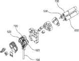
图2是分解透视图,其图解图1的腹腔镜手术仪器的驱动部件;FIG. 2 is an exploded perspective view illustrating drive components of the laparoscopic surgical instrument of FIG. 1;
图3是分解透视图,其图解图1的腹腔镜手术仪器的柔性接头、头和钳子;Figure 3 is an exploded perspective view illustrating the flexible joint, head and forceps of the laparoscopic surgical instrument of Figure 1;
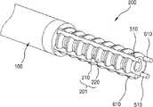
图4是图1的柔性接头的放大透视图;Figure 4 is an enlarged perspective view of the flexible joint of Figure 1;
图5是横截面图,其详细地图解了图4的柔性接头的小环和大环;Figure 5 is a cross-sectional view illustrating in detail the small and large rings of the flexible joint of Figure 4;
图6是图5的大环的放大透视图;Figure 6 is an enlarged perspective view of the macroring of Figure 5;
图7是图4的柔性接头的外盖的放大透视图;Figure 7 is an enlarged perspective view of the outer cover of the flexible joint of Figure 4;
图8是根据本发明的实施方式具有小直径轴的腹腔镜手术仪器的纵向驱动部件的放大透视图;Figure 8 is an enlarged perspective view of a longitudinal drive component of a laparoscopic surgical instrument having a small diameter shaft according to an embodiment of the present invention;
图9是具有小直径轴的腹腔镜手术仪器的横向驱动部件的放大透视图;Figure 9 is an enlarged perspective view of a lateral drive component of a laparoscopic surgical instrument having a small diameter shaft;
图10是放大透视图,其图解带有柔性接头、纵向驱动金属丝和横向驱动金属丝的图3的头的组装状态;10 is an enlarged perspective view illustrating the assembled state of the head of FIG. 3 with flexible joints, longitudinal drive wires, and transverse drive wires;
图11和12是分解透视图,其图解图10的钳子;Figures 11 and 12 are exploded perspective views illustrating the pliers of Figure 10;
图13是透视图,其显示根据本发明的实施方式具有小直径轴的腹腔镜手术仪器的钳子驱动部件的细节;Figure 13 is a perspective view showing details of a forceps drive component of a laparoscopic surgical instrument having a small diameter shaft according to an embodiment of the present invention;
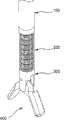
图14是透视图,其显示根据本发明的实施方式具有小直径轴的腹腔镜手术仪器的操作状态,其中头由纵向驱动部件纵向驱动;14 is a perspective view showing the operating state of a laparoscopic surgical instrument with a small diameter shaft according to an embodiment of the present invention, wherein the head is longitudinally driven by a longitudinal drive member;
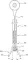
图15是透视图,其显示根据本发明的实施方式具有小直径轴的腹腔镜手术仪器的操作状态,其中头由横向驱动部件横向驱动;15 is a perspective view showing the operating state of a laparoscopic surgical instrument with a small diameter shaft according to an embodiment of the present invention, wherein the head is laterally driven by a lateral drive member;
图16是俯视平面图,其显示在根据本发明的实施方式具有小直径轴的腹腔镜手术仪器中头在轴周围的旋转状态;和16 is a top plan view showing the state of rotation of the head around the shaft in a laparoscopic surgical instrument having a small diameter shaft according to an embodiment of the present invention; and
图17是透视图,其显示在根据本发明的实施方式具有小直径轴的腹腔镜手术仪器中钳子的操作状态。Fig. 17 is a perspective view showing an operational state of forceps in a laparoscopic surgical instrument having a small-diameter shaft according to an embodiment of the present invention.
【具体实施方式】【Detailed ways】
从下面的详述结合附图,本发明的特征和其它优点将能被更清楚地理解。在下文中,具有小直径轴的腹腔镜手术仪器将根据本发明的优选实施方式参考附图进行更详细地描述。The features and other advantages of the present invention will be more clearly understood from the following detailed description taken in conjunction with the accompanying drawings. Hereinafter, a laparoscopic surgical instrument having a small-diameter shaft will be described in more detail with reference to the accompanying drawings according to preferred embodiments of the present invention.
参考图1至3,具有小直径轴的腹腔镜手术仪器包括长轴100,其被插入到腹部切口中;柔性接头200,其与轴100的远端部分连接;头300,其与柔性接头200的底部连接;钳子400(手术仪器),其被安装在头300的底部;和驱动部分500、600和700,其每一个驱动柔性接头200和钳子400的各自部分。1 to 3, a laparoscopic surgical instrument with a small diameter shaft includes a
轴100在手术操作期间被插入到操作区域,其被形成为内部带有空管的细长形状,并且轴100的两端是开放的。The
参考图4至6,柔性接头200被构造成具有安排在一排中的多个环201。每个环201由小环210和大环220组成。小环210和大环220具有相同的内径“D”。原因是可以在柔性接头200内部形成具有均匀直径的狭窄洞,从而金属丝或电力线可穿过直的洞。每个大环220被提供有导槽221,用于在其外周的四部分插入将在下面描述的纵向驱动金属丝510和横向驱动金属丝610。导槽221以90度间隔形成于大环的外周中。大环220可优选地被制备得比小环210大导槽221的深度“L”。Referring to Figures 4 to 6, the flexible joint 200 is configured with a plurality of
柔性接头200的环201可由硬物质诸如钢或具有弹性的软物质诸如橡胶制成。The
如上述配制的柔性接头200分别地在其顶部与轴100相连接,并且在其底部与头300相连接。The flexible joint 200 configured as above is connected to the
参考图4和7,柔性接头200被覆盖有圈形外盖230,其通过以相同直径重复缠绕钢丝而制成。外盖230防止当柔性接头200弯曲时纵向驱动金属丝510和横向驱动金属丝610移动出大环220的导槽221。4 and 7, the flexible joint 200 is covered with a ring-shaped outer cover 230, which is made by repeatedly winding a steel wire with the same diameter. The outer cover 230 prevents the
外盖230被图解和描述成如上的圈形形状。然而,本发明不限于上述形状,并且外盖230可由软管制成,所述软管在环向上不能膨胀和收缩,而在纵向上膨胀和收缩。对于这种软管,可以使用褶状软管或柔性的管。The outer cover 230 is illustrated and described as being in the shape of a ring as above. However, the present invention is not limited to the above-mentioned shape, and the outer cover 230 may be made of a hose that cannot expand and contract in a hoop direction but expands and contracts in a longitudinal direction. For such a hose, a pleated hose or a flexible tube can be used.
参考图8和14,纵向驱动部件500驱动柔性接头200在头300的纵向方向上折叠,并且包括纵向驱动金属丝510、纵向驱动辊520和纵向驱动马达530。Referring to FIGS. 8 and 14 , the
纵向驱动金属丝510被供给一条金属丝。纵向驱动金属丝510以这样的方式弯曲,以致于相对端部分511在一个方向上结合,然后其末端部分511定位的远端被插入到轴100的远端。插入到轴100中的纵向驱动金属丝510被线性插入到柔性接头200中大环220的导槽221的两纵向槽组(参见图6)中,并且两末端部分511与头300的两纵向连接端相连。纵向驱动金属丝510的连接部分512位于轴100的顶部(近端部分)并且被缠绕在与纵向驱动马达530相连的纵向驱动辊520上。优选地,纵向驱动金属丝510可被缠绕以便可在纵向驱动辊520的两个方向上转动。The
缠绕在纵向驱动辊520上的纵向驱动金属丝510在纵向驱动辊520旋转的方向上运动。当纵向驱动辊520在右方向上旋转时,纵向驱动金属丝510的右侧末端部分511出来并且相对的左侧末端部分511被插入到其中。The
参考图9和15,横向驱动部件600驱动柔性接头200在头300的横向方向上折叠,并且包括横向驱动金属丝610、横向驱动辊620和横向驱动马达630。Referring to FIGS. 9 and 15 , the
参考如上配置的横向驱动部分600,横向驱动金属丝610被供给象纵向驱动金属丝510一样的一条金属丝(参见图8)。横向驱动金属丝610以这样的方式弯曲,以致于相对端部分611在一个方向上结合,然后其末端部分611定位的远端被插入到轴100的远端。插入到轴100中的横向驱动金属丝610被线性插入到柔性接头200中大环220的导槽221中的两横向导槽(参考图6的221)中,并且两末端部分611与头300的两横向连接端相连。横向驱动金属丝610的连接部分612位于轴100的顶部(近端部分)并且被缠绕在与横向驱动马达630相连的纵向驱动辊620上。Referring to the
缠绕在横向驱动辊620上的横向驱动金属丝610在横向驱动辊520旋转的方向上运动。当横向驱动辊620基于轴100在右方向上旋转时,横向驱动金属丝610的右侧末端部分611出来并且相对的左侧末端部分611被插入到其中。The
参考图10,头300具有与轴相同的外径(参考图1的100)并且被连接到柔性接头200的远侧底端。纵向驱动金属丝510的两末端部分511和横向驱动金属丝610的两末端部分611被分别连接到纵向方向的连接面的两侧以及横向方向的连接面的两侧。在头300的远侧底端,各种手术仪器被连接或构造成一体。Referring to FIG. 10 , the
参考图11至13,钳子400包括被连接到主体310上的一对钳爪410,其与头300、驱动辊420和钳子驱动部件700连接。Referring to FIGS. 11 to 13 , the
钳爪410在其顶端部分形成有刺穿枢轴插入开口411,以及沿着爪410内的倾角延伸的导缝412。驱动辊420被旋转安装在主体310上并且在两侧形成有偏心突出的驱动销421。钳子驱动部件700包括钳子驱动金属丝710、钳子驱动辊720和钳子驱动马达730。The
对于如上构造的钳子400的装配顺序,经由头300中的通孔插入的钳子驱动金属丝710的折叠部分712被缠绕在驱动辊420的外周上。驱动辊420与主体310旋转连接。两侧上的钳爪410以这样的方式相互连接,以致于装配在主体310上的驱动辊420的驱动销421被分别插入到导缝412。最后,主体310和钳爪410被插入到头300中,并且固定轴311被插入到主体310和钳爪410的枢轴插入开口411中。For the assembly sequence of the
参考图13和17,如上配置的钳子400由钳子驱动部件700驱动,钳子驱动部件700包括钳子驱动金属丝710、钳子驱动辊720和钳子驱动马达730。Referring to FIGS. 13 and 17 , the
钳子驱动金属丝710以这样的方式被折叠成两半,以致于折叠部分712穿过轴100和柔性接头200的中空开放部分并且围绕啮合在头300的主体310上的驱动辊420的外周。这里,钳子驱动金属丝710的相对末端与安装在轴100的近侧顶端上的钳子驱动辊720连接。钳子驱动辊720可通过钳子驱动马达730转动,由此使得钳子驱动金属丝710在一个方向上旋转。The forceps drive
在本发明的示例性实施方式中,具有小直径轴的腹腔镜手术仪器可与机器人辅助的腹腔镜手术的从动机器人(未显示)连接而使用。然而,本发明并不限于此,并且对于单独操作和操纵的腹腔镜手术来说,可被用作带有固定于其上的分开的操纵工具的腹腔镜手术仪器。In an exemplary embodiment of the invention, a laparoscopic surgical instrument having a small diameter shaft may be used in connection with a slave robot (not shown) for robot-assisted laparoscopic surgery. However, the present invention is not limited thereto, and may be used as a laparoscopic surgical instrument with a separate manipulation tool fixed thereto for laparoscopic surgery that is operated and manipulated alone.
将详细地更多描述根据本发明的具有小直径轴的腹腔镜手术仪器——其被制成具有上述外形——的操作。The operation of the laparoscopic surgical instrument having a small-diameter shaft according to the present invention, which is made to have the above-mentioned shape, will be described more in detail.
参考图8和14,与纵向驱动辊520连接的纵向驱动马达530需要进行旋转以便通过纵向地弯曲柔性接头200在纵向上转动头300。与纵向驱动马达530连接的纵向驱动辊520可通过纵向驱动马达530的旋转力朝一个方向旋转一定度数的角度。当纵向驱动辊520顺时针方向旋转时,在纵向驱动辊520周围缠绕的纵向驱动金属丝510的左侧可被缠绕在纵向驱动辊520周围,并且其右侧可从纵向驱动辊520上松开。当以这样的方式纵向驱动金属丝510的左侧收缩并且纵向驱动金属丝510的右侧延伸时,柔性接头200被压缩以减少头300——与纵向驱动金属丝510的左侧连接——和轴100之间的空间。形成柔性接头200的小环210和大环220由于上述向下的压力弯曲而同时作圆周运动。当柔性接头200被弯曲而同时作圆周运动时,头300在轴的100周围旋转向纵向的左侧。Referring to FIGS. 8 and 14 , the
与上述运动相反,为了使头300在纵向的右侧旋转,纵向驱动马达530需要逆时针方向旋转。当纵向驱动马达530逆时针方向旋转时,与纵向驱动马达530相连的纵向驱动辊520逆时针方向旋转,并且缠绕在纵向驱动辊520周围的纵向驱动金属丝510的左侧延伸并且纵向驱动金属丝510的右侧收缩。当纵向驱动金属丝510的长度基于上述纵向驱动辊变化时,柔性接头200通过纵向驱动金属丝510在轴100周围向纵向的右侧弯曲,并且头300转向右侧。Contrary to the above movement, in order to rotate the
能使柔性接头200纵向弯曲的纵向驱动部件500可使头300在纵向上向上和向下旋转90度。The
参考图9和15,开动横向驱动部件600的横向驱动马达630以便使柔性接头200横向弯曲。当横向驱动马达630旋转时,横向驱动辊620可朝一个方向转动一定度数的角度并且横向驱动金属丝610被缠绕在横向驱动辊620周围。当横向驱动辊620顺时针方向转动时,横向驱动金属丝610的左侧可被缠绕在横向驱动辊620周围,并且横向驱动金属丝610的右侧可被松开。因此,横向驱动金属丝610的左侧可以收缩并且横向驱动金属丝610的右侧可在横向驱动辊620周围延伸,并且柔性接头200被压缩以在头300——与横向驱动金属丝610的左末端部分611连接——和轴100之间左向上减少。此时,形成柔性接头200的小环210和大环220由于向下的压力左向上弯曲而同时作圆周运动。柔性接头200如上左向上被弯曲,并且头300在轴的100周围旋转向横向的左侧。Referring to FIGS. 9 and 15 , the
与上述运动相反,为了使头300转向横向的右侧,横向驱动马达630逆时针方向旋转。当横向驱动马达630逆时针方向旋转时,缠绕在横向驱动辊620周围的横向驱动金属丝610的左侧延伸并且横向驱动金属丝610的右侧收缩。当横向驱动金属丝610的长度变化时,柔性接头200向右侧弯曲,并且头300可在轴100周围向横向的右侧旋转。Contrary to the above movement, in order to turn the
如上弯曲的柔性接头200可在所述轴的长轴周围横向的左/右侧使头300旋转90度。Flex joint 200 bent as above allows
参考图16,分别在纵向和横向90度内弯曲的柔性接头200可与纵向驱动部件500和横向驱动部件600一起使用,并且当纵向驱动部件500和横向驱动部件600同时操作时,头300可绕轴100全方位地旋转360度。Referring to FIG. 16 , the flexible joint 200 bent within 90 degrees longitudinally and laterally respectively can be used together with the
参考图17,在头300上形成的钳子400可以经由通过旋转钳子驱动马达730转动钳子驱动辊720而开动。当钳子驱动辊720转动时,钳子驱动金属丝710的一侧被缠绕在钳子驱动辊720周围,并且钳子驱动金属丝710的另一侧被松开。此时,钳子驱动金属丝710的折叠部分712在驱动辊420周围旋转,并且驱动辊420在钳子驱动金属丝710的旋转方向上转动。当钳子驱动辊720通过借助钳子驱动马达730顺时针方向转动时,钳子驱动金属丝710与钳子驱动辊720一起顺时针方向旋转。此时,与钳子驱动金属丝710的折叠部分712旋转连接的驱动辊420可与钳子驱动金属丝710一起顺时针方向旋转。当驱动辊420如上顺时针方向转动时,两钳爪410——其中导缝412与驱动销421连接——可通过驱动辊420的旋转向上闭合,直至相对侧相互形成接触。Referring to FIG. 17 , the
为了打开钳爪410,钳子驱动辊720逆时针方向转动。当钳子驱动辊720逆时针方向转动时,钳子驱动金属丝710也逆时针方向旋转并且与钳子驱动金属丝710相连的驱动辊420也逆时针方向旋转,并且两钳爪410,其中导缝412与驱动辊420的驱动销421连接,通过向两个方向移动而打开。To open the
如上所示,应当理解,本领域技术人员可以在没有背离本发明的范围和精神的情况下进行替换、变化或将实施方式修改成各种形式。因此,前述实施方式应当被看作示例性的,而不是限制性的。本发明的范围不受上述详述限定,而是受本发明所附的权利要求限定。还应当理解,源自权利要求的定义和范围的所有变化或修饰及其等同形式都落入本发明的范围内。As above, it should be understood that those skilled in the art may substitute, change or modify the embodiments into various forms without departing from the scope and spirit of the present invention. Therefore, the foregoing embodiments should be considered as illustrative, not restrictive. The scope of the invention is not defined by the above detailed description, but is defined by the claims appended hereto. It should also be understood that all changes or modifications derived from the definition and scope of the claims and their equivalents fall within the scope of the present invention.
Claims (12)
Applications Claiming Priority (3)
| Application Number | Priority Date | Filing Date | Title |
|---|---|---|---|
| KR10-2007-0104642 | 2007-10-17 | ||
| KR1020070104642AKR100911248B1 (en) | 2007-10-17 | 2007-10-17 | Small laparoscopic surgical instruments |
| PCT/KR2008/006112WO2009051418A2 (en) | 2007-10-17 | 2008-10-16 | Small caliber laparoscope surgical apparatus |
Publications (2)
| Publication Number | Publication Date |
|---|---|
| CN101873831Atrue CN101873831A (en) | 2010-10-27 |
| CN101873831B CN101873831B (en) | 2012-09-26 |
Family
ID=40567964
Family Applications (1)
| Application Number | Title | Priority Date | Filing Date |
|---|---|---|---|
| CN2008801177586AExpired - Fee RelatedCN101873831B (en) | 2007-10-17 | 2008-10-16 | Small Bore Laparoscopic Surgical Instruments |
Country Status (6)
| Country | Link |
|---|---|
| US (1) | US8702748B2 (en) |
| EP (1) | EP2200516B1 (en) |
| JP (1) | JP5111612B2 (en) |
| KR (1) | KR100911248B1 (en) |
| CN (1) | CN101873831B (en) |
| WO (1) | WO2009051418A2 (en) |
Cited By (4)
| Publication number | Priority date | Publication date | Assignee | Title |
|---|---|---|---|---|
| CN103732161A (en)* | 2011-08-15 | 2014-04-16 | 直观外科手术操作公司 | Medical devices with soft jaws and/or flexible wrist mechanisms |
| CN111184557A (en)* | 2020-03-01 | 2020-05-22 | 杨红伟 | Neurosurgery robot driving piece |
| CN113951948A (en)* | 2021-11-26 | 2022-01-21 | 杭州华匠医学机器人有限公司 | Surgical instrument control unit |
| CN115645067A (en)* | 2022-11-15 | 2023-01-31 | 电子科技大学 | Spiral flexible single-hole surgical robot structure based on twisted pair line driving |
Families Citing this family (16)
| Publication number | Priority date | Publication date | Assignee | Title |
|---|---|---|---|---|
| KR101126288B1 (en) | 2010-07-02 | 2012-03-20 | 한국과학기술원 | Surgery tools with rolling of end effector for minimally invasive surgery |
| KR101684863B1 (en)* | 2010-11-16 | 2016-12-12 | (주)미래컴퍼니 | Instrument of surgical apparatus having multi-function |
| US10219869B2 (en) | 2014-02-12 | 2019-03-05 | Covidien Lp | Surgical end effectors and pulley assemblies thereof |
| EP3104791B1 (en)* | 2014-02-12 | 2022-04-27 | Covidien LP | Surgical end effectors and pulley assemblies thereof |
| CN105979901B (en)* | 2014-02-12 | 2019-03-26 | 柯惠Lp公司 | Surgical end effector and its pulley assembly |
| US9872722B2 (en) | 2014-05-05 | 2018-01-23 | Covidien Lp | Wake-up system and method for powered surgical instruments |
| CN106659538B (en) | 2014-08-13 | 2019-05-10 | 柯惠Lp公司 | Robot-controlled gripping with mechanical advantages |
| EP3179952B1 (en) | 2014-08-13 | 2019-03-20 | Covidien LP | Robotically controlled mechanical advantage gripper |
| KR101726083B1 (en) | 2015-12-15 | 2017-04-11 | (주)선메딕스 | Device of tissue and blood vessel sealing and cutting |
| CN105796138B (en)* | 2016-05-11 | 2018-04-10 | 天津大学 | Flexible Minimally Invasive Surgery apparatus based on natural cavity |
| CN105943095B (en)* | 2016-05-11 | 2018-04-10 | 天津大学 | A kind of Minimally Invasive Surgery apparatus with flexible wrist |
| CA3103224A1 (en)* | 2018-06-17 | 2019-12-26 | Memic Innovative Surgery Ltd. | Surgical articulated arm |
| KR102043627B1 (en)* | 2019-03-18 | 2019-11-12 | 맥스폴 주식회사 | Flexible dissection apparatus |
| CN112545612B (en)* | 2020-12-04 | 2022-11-01 | 哈尔滨工业大学 | A clamp head mechanism of a single-hole surgical robotic arm |
| GB2603929B (en)* | 2021-02-19 | 2023-06-14 | Prec Robotics Limited | An actuation mechanism |
| KR102573523B1 (en)* | 2021-06-11 | 2023-09-06 | 한국기계연구원 | Flexible surgical instrument capable of steering a tip |
Family Cites Families (24)
| Publication number | Priority date | Publication date | Assignee | Title |
|---|---|---|---|---|
| JPS5878639A (en) | 1981-11-04 | 1983-05-12 | オリンパス光学工業株式会社 | Endoscope |
| JPH045126Y2 (en) | 1987-09-03 | 1992-02-14 | ||
| DE9106506U1 (en)* | 1991-05-27 | 1991-07-25 | Storz, Karl, Dr.med.h.c., 7200 Tuttlingen | Surgical forceps |
| JPH0838495A (en)* | 1994-07-29 | 1996-02-13 | Olympus Optical Co Ltd | Endoscopec processing tool |
| US5752973A (en)* | 1994-10-18 | 1998-05-19 | Archimedes Surgical, Inc. | Endoscopic surgical gripping instrument with universal joint jaw coupler |
| JPH08224241A (en) | 1995-02-22 | 1996-09-03 | Olympus Optical Co Ltd | Medical manipulator |
| JPH09276283A (en) | 1996-04-09 | 1997-10-28 | Olympus Optical Co Ltd | Forceps for endoscope |
| US5904702A (en)* | 1997-08-14 | 1999-05-18 | University Of Massachusetts | Instrument for thoracic surgical procedures |
| US6206903B1 (en)* | 1999-10-08 | 2001-03-27 | Intuitive Surgical, Inc. | Surgical tool with mechanical advantage |
| US20030135204A1 (en)* | 2001-02-15 | 2003-07-17 | Endo Via Medical, Inc. | Robotically controlled medical instrument with a flexible section |
| US6544274B2 (en) | 2001-05-02 | 2003-04-08 | Novare Surgical Systems, Inc. | Clamp having bendable shaft |
| US6817974B2 (en)* | 2001-06-29 | 2004-11-16 | Intuitive Surgical, Inc. | Surgical tool having positively positionable tendon-actuated multi-disk wrist joint |
| JP3631450B2 (en) | 2001-08-22 | 2005-03-23 | 株式会社東芝 | manipulator |
| JP3912251B2 (en)* | 2002-10-02 | 2007-05-09 | 株式会社日立製作所 | manipulator |
| US7090637B2 (en)* | 2003-05-23 | 2006-08-15 | Novare Surgical Systems, Inc. | Articulating mechanism for remote manipulation of a surgical or diagnostic tool |
| US7686826B2 (en)* | 2003-10-30 | 2010-03-30 | Cambridge Endoscopic Devices, Inc. | Surgical instrument |
| KR100585458B1 (en) | 2004-04-13 | 2006-06-07 | 국립암센터 | Laparoscopic Surgery Robot System |
| KR100617974B1 (en)* | 2004-04-22 | 2006-08-31 | 한국과학기술원 | Laparoscopic device capable of command following |
| JP4373879B2 (en) | 2004-08-26 | 2009-11-25 | 株式会社日立製作所 | Surgical instruments |
| US20060289602A1 (en) | 2005-06-23 | 2006-12-28 | Ethicon Endo-Surgery, Inc. | Surgical instrument with articulating shaft with double pivot closure and single pivot frame ground |
| US7575144B2 (en)* | 2006-01-31 | 2009-08-18 | Ethicon Endo-Surgery, Inc. | Surgical fastener and cutter with single cable actuator |
| US8721630B2 (en) | 2006-03-23 | 2014-05-13 | Ethicon Endo-Surgery, Inc. | Methods and devices for controlling articulation |
| AU2007201204B2 (en)* | 2006-03-23 | 2012-07-12 | Ethicon Endo-Surgery, Inc. | Articulating endoscopic accessory channel |
| JP5128904B2 (en)* | 2007-10-31 | 2013-01-23 | 株式会社東芝 | manipulator |
- 2007
- 2007-10-17KRKR1020070104642Apatent/KR100911248B1/ennot_activeExpired - Fee Related
- 2008
- 2008-10-16JPJP2010529868Apatent/JP5111612B2/ennot_activeExpired - Fee Related
- 2008-10-16WOPCT/KR2008/006112patent/WO2009051418A2/enactiveApplication Filing
- 2008-10-16USUS12/738,478patent/US8702748B2/ennot_activeExpired - Fee Related
- 2008-10-16EPEP08839041.4Apatent/EP2200516B1/ennot_activeNot-in-force
- 2008-10-16CNCN2008801177586Apatent/CN101873831B/ennot_activeExpired - Fee Related
Cited By (4)
| Publication number | Priority date | Publication date | Assignee | Title |
|---|---|---|---|---|
| CN103732161A (en)* | 2011-08-15 | 2014-04-16 | 直观外科手术操作公司 | Medical devices with soft jaws and/or flexible wrist mechanisms |
| CN111184557A (en)* | 2020-03-01 | 2020-05-22 | 杨红伟 | Neurosurgery robot driving piece |
| CN113951948A (en)* | 2021-11-26 | 2022-01-21 | 杭州华匠医学机器人有限公司 | Surgical instrument control unit |
| CN115645067A (en)* | 2022-11-15 | 2023-01-31 | 电子科技大学 | Spiral flexible single-hole surgical robot structure based on twisted pair line driving |
Also Published As
| Publication number | Publication date |
|---|---|
| JP5111612B2 (en) | 2013-01-09 |
| JP2011500202A (en) | 2011-01-06 |
| EP2200516A2 (en) | 2010-06-30 |
| KR20090039163A (en) | 2009-04-22 |
| WO2009051418A2 (en) | 2009-04-23 |
| US20100280543A1 (en) | 2010-11-04 |
| CN101873831B (en) | 2012-09-26 |
| EP2200516A4 (en) | 2010-12-01 |
| WO2009051418A3 (en) | 2009-07-23 |
| EP2200516B1 (en) | 2013-08-14 |
| US8702748B2 (en) | 2014-04-22 |
| KR100911248B1 (en) | 2009-08-07 |
Similar Documents
| Publication | Publication Date | Title |
|---|---|---|
| CN101873831A (en) | Small-caliber laparoscopic surgical instrument | |
| JP7073600B2 (en) | Surgical instruments with nail boxes and nail boxes | |
| CN104188710B (en) | Medical manipulator | |
| US9186050B2 (en) | Medical treatment endoscope with a positioning mechanism | |
| US20110238084A1 (en) | Surgical instrument | |
| JP4354216B2 (en) | LINKING DEVICE FOR TREATMENT TOOL AND TREATMENT TOOL | |
| CN101351236B (en) | An active sleeve for biosensing and surgery | |
| KR102347945B1 (en) | Surgical instrument equipment appropriate for mini-invasive surgery | |
| JP2012522553A (en) | Surgical instruments | |
| CN102448386B (en) | Disposal equipment | |
| CN111970985B (en) | Low-friction small medical tool with easy-to-assemble components | |
| JP6709928B1 (en) | Minimally invasive surgical equipment | |
| JP5200055B2 (en) | Endoscopic surgical forceps | |
| JP2025515328A (en) | Method and system for robotic single port laparoscopic access - Patents.com | |
| Li et al. | A novel endoscope design using spiral technique for robotic-assisted endoscopy insertion | |
| WO2022212261A1 (en) | Devices, systems, and methods for performing suturing procedures | |
| JP3539124B2 (en) | Trocar with angle mechanism | |
| WO2017119108A1 (en) | Endoscope treatment device | |
| KR100995776B1 (en) | Surgical Instruments, Master Interface of Surgical Robot for Operating It and Driving Method of Surgical Robot | |
| JP2024531680A (en) | Surgical Instruments End Tools | |
| KR20110012822A (en) | Surgical Robot | |
| CN219289608U (en) | Bending surgical instrument | |
| KR20130025923A (en) | Instrument for minimally invasive surgery having shaft including inner torque transmission member |
Legal Events
| Date | Code | Title | Description |
|---|---|---|---|
| C06 | Publication | ||
| PB01 | Publication | ||
| C10 | Entry into substantive examination | ||
| SE01 | Entry into force of request for substantive examination | ||
| C14 | Grant of patent or utility model | ||
| GR01 | Patent grant | ||
| C17 | Cessation of patent right | ||
| CF01 | Termination of patent right due to non-payment of annual fee | Granted publication date:20120926 Termination date:20131016 |