CN101872911A - Rotary selection push-out type multinational power supply adapter - Google Patents
Rotary selection push-out type multinational power supply adapterDownload PDFInfo
- Publication number
- CN101872911A CN101872911ACN 201010183801CN201010183801ACN101872911ACN 101872911 ACN101872911 ACN 101872911ACN 201010183801CN201010183801CN 201010183801CN 201010183801 ACN201010183801 ACN 201010183801ACN 101872911 ACN101872911 ACN 101872911A
- Authority
- CN
- China
- Prior art keywords
- pin
- pins
- upper cover
- base
- positioning
- Prior art date
- Legal status (The legal status is an assumption and is not a legal conclusion. Google has not performed a legal analysis and makes no representation as to the accuracy of the status listed.)
- Granted
Links
Images


Landscapes
- Connector Housings Or Holding Contact Members (AREA)
- Details Of Connecting Devices For Male And Female Coupling (AREA)
- Coupling Device And Connection With Printed Circuit (AREA)
Abstract
Translated fromChinese
Description
Translated fromChinese技术领域technical field
本发明涉及适用于电器与电源连接的电源插头领域技术,尤其是指一种旋转选择推出式多国电源转接器。The invention relates to the technology in the field of power plugs suitable for connecting electrical appliances to power sources, in particular to a rotary selection push-out multi-country power adapter.
背景技术Background technique
多国用电源转接器系一种集多国标准之插头和插座功能于一身的电器产品,其主要用于需要经常出国经商或出国旅游的人士携带使用,通过该多国电源转接器可提供人们出国时随身携带之电器产品(如笔记本电脑、手机、MP3、MP4、摄像机等)的电源转接之便利。The multi-country power adapter is an electrical product that integrates the functions of multi-national standard plugs and sockets. It is mainly used by people who often go abroad for business or travel. The multi-country power adapter can provide people with It is convenient for power transfer of electrical products (such as notebook computers, mobile phones, MP3, MP4, video cameras, etc.) that are always carried with you.
目前,市面上出现有一些多国用电源转接器,其大多数是由多个不同国家的转接头组合而成,当人们选用其一组插头插置于相应外部插座时,其余各组插头常常会发生凸伸外露状况,极易有触电或短路现象之危险;因此,为解决此类问题,很多人提出相关的专利申请,如参阅台湾专利公告号TW541768、中国专利公告号CN539187A等公开之个应多国插头之内容。At present, there are some multi-country power adapters on the market, most of which are composed of adapters from different countries. There will be a protruding and exposed situation, and there is a risk of electric shock or short circuit; therefore, in order to solve this problem, many people have filed related patent applications, such as referring to Taiwan Patent No. TW541768, China Patent No. CN539187A, etc. Respond to the content of multi-country plugs.
如台湾专利TW541768所公开一种多国型转接插座,其通过内侧对应电源插脚动作之位置组设有保险装置及相应的安全遮板,令其控制杆及定位块得以推钮连动而呈左、右位移之状态,以强制限制各线电源插脚保持定位,惟仅能使单一组电源插脚不受限制而可外伸导插之作用,使转接插座可具有强制性之防护功效,藉此以增进使用时之安全性;但是,对于目前产品追求轻、薄、短、小之设计理念,需要内部增设此类保险装置及相应安全遮板,其空间有限,不利于组装;特别是其结构复杂,在操作按扭时常常会遇到卡死或失灵等现象,给使用带来局限性。For example, Taiwan patent TW541768 discloses a multi-country adapter socket, which is equipped with a safety device and a corresponding safety shield through the position corresponding to the action of the power pin on the inner side, so that the control rod and the positioning block can be pushed to the left. , The state of right displacement is to forcefully restrict the positioning of the power pins of each line, but it can only make a single set of power pins unrestricted and can be extended and inserted, so that the adapter socket can have a mandatory protective effect, thereby In order to improve the safety during use; however, for the current design concept of light, thin, short and small, it is necessary to add such safety devices and corresponding safety shutters inside, and its space is limited, which is not conducive to assembly; especially its structure It is complicated, and often encounters phenomena such as stuck or malfunctioning when operating the buttons, which brings limitations to the use.
再参阅中国专利CN1539187A所公开一种电源插头,其且一个外壳和在外壳中可移动地支承的至少两个不同标准化的插头接点,所述插头接点分别具有两个导电触针,这些触针可以沿着滑移行程从外壳移出到一个有效位置中,以及移入到外壳中的一个无效位置中,其重点在于还至少一个制动体,它相对于外壳和插头接头是活动,并通过一个插头接点固定在无效位置外部的一个位置上,在这个位置上所述制动体设置在其余插头接点的滑移行程上并由此防止另一插头接点从无效位置移进有效位置中;该技术方案是利用在滑移行程间设置之制动体来限制其余插头接点位移,由于制动体呈活动结构,操作时会因其松动、晃动而发生卡死、失灵现象,本专利还公开了结合利用保险体等结构来实现本功能,而单纯使用这些结构来达到限制作用会在操作方便存在插头位移顺畅之现象,所以还需结合一操作钮之结构不共同作用才能保证操作时插头位移顺畅,如此结构十分复杂,操作时必须一手按住操作钮,同时另一手拔动所需插头才能使插头伸出,故操作起来比较麻烦,长期使用状态下亦会产生失灵现象;本申请人鉴于技术方案作进一步研究,特提出本申请。Referring again to a power plug disclosed in Chinese patent CN1539187A, it has a housing and at least two different standardized plug contacts movably supported in the housing, and the plug contacts respectively have two conductive contact pins, and these contact pins can Moving out of the housing along the sliding path into an active position and into an inactive position in the housing, it is essential that there is also at least one braking body, which is movable relative to the housing and the plug connection and passes through a plug contact fixed in a position outside the ineffective position, in which the braking body is arranged on the sliding travel of the remaining plug contacts and thus prevents the other plug contact from moving from the inactive position into the active position; the technical solution is The brake body installed between the sliding strokes is used to limit the displacement of the remaining plug contacts. Since the brake body is in a movable structure, it will be stuck and malfunction due to looseness and shaking during operation. This patent also discloses the combined use of insurance Body and other structures to achieve this function, but simply using these structures to achieve the restrictive effect will cause smooth plug displacement in the convenience of operation, so it is necessary to combine the structure of an operation button to ensure smooth plug displacement during operation, such a structure It is very complicated. It is necessary to press the operation button with one hand and pull the required plug with the other hand to make the plug stretch out. Therefore, it is cumbersome to operate, and malfunctions will also occur under long-term use; research, this application is proposed.
发明内容Contents of the invention
本发明针对现有技术存在之缺失,其主要目的是提供一种旋转选择推出式多国电源转接器,其运用简单的结构设计及简易的构件组合,具有结构简单、操作方便且插头伸缩活动顺畅之特点;同时,其可选择性伸出单一之规格插脚使用,其余插脚隐藏于壳体内,使用更为安全可靠。The present invention aims at the deficiencies existing in the prior art, and its main purpose is to provide a rotary selectable push-out multi-country power adapter, which uses a simple structural design and simple component combination, and has the advantages of simple structure, convenient operation, and smooth plug expansion and contraction. At the same time, it can selectively extend a single standard pin for use, and the rest of the pins are hidden in the housing, which is safer and more reliable.
为实现上述目的,本发明采用如下之技术方案:To achieve the above object, the present invention adopts the following technical solutions:
一种旋转选择推出式多国电源转接器,包括有壳体和设置于壳体中的插座、至少两种不同规格的插脚,该壳体包括上盖和底座,该底座相对一中心转轴可转动地组接于上盖上,该插座安装于该上盖中,该不同规格的插脚安装于该底座中并随底座同步转动,且该不同规格的插脚围绕该中心转轴周向分布,同时,各插脚相对于该中心转轴可平行滑动的设置,使各插脚具有一滑移伸出壳体外的工作位置和滑移缩回于壳体内的隐藏位置;该上盖的侧壁上设置有一平行于插脚伸出方向延伸的定位滑槽,对应该定位滑槽设置有可沿定位滑槽自由滑动的滑移组件,当其中一插脚旋转至该滑移组件的功能区时,由该滑移组件推动该插脚伸出壳体外之其工作位置。A rotary selective push-out multi-country power adapter, including a housing, a socket set in the housing, and pins of at least two different specifications. The housing includes an upper cover and a base, and the base is rotatable relative to a central rotating shaft. The ground is assembled on the upper cover, the socket is installed in the upper cover, the pins of different specifications are installed in the base and rotate synchronously with the base, and the pins of different specifications are circumferentially distributed around the central rotating shaft, and at the same time, each The pins can slide parallel to the central shaft, so that each pin has a working position that slides out of the housing and a hidden position that slides back into the housing; the side wall of the upper cover is provided with a The positioning chute extending in the extending direction is provided with a sliding assembly that can slide freely along the positioning chute. When one of the pins rotates to the functional area of the sliding assembly, the sliding assembly pushes the sliding assembly. The prongs extend out of the housing to their working position.
作为一种优选方案,所述插脚的外侧设置有两导电触点,在靠近定位滑槽内侧设置有两长条导电触片,该长条导电触片的上端与插座电连接,长条导电触片的下端沿插脚伸出方向延伸;当插脚旋转至该滑移组件的功能区时,该插脚上的两导电触点分别与该两长条导电触片抵触电连接,并在插脚滑移伸出壳体的过程中,该两导电触点亦始终与该两长条导电触片抵触电连接。As a preferred solution, two conductive contacts are arranged on the outside of the pin, and two long conductive contacts are arranged on the inner side of the positioning chute. The upper ends of the long conductive contacts are electrically connected to the socket, and the long conductive contacts The lower end of the piece extends along the extension direction of the pin; when the pin rotates to the functional area of the sliding component, the two conductive contacts on the pin respectively resist and electrically connect with the two long conductive contact pieces, and when the pin slides and extends During the process of exiting the housing, the two conductive contacts are always electrically connected to the two long conductive contact pieces.
作为一种优选方案,所述上盖内壁面靠近定位滑槽两侧的位置分别设置有一容置槽,前述长条导电触片嵌装于该容置槽中。As a preferred solution, an accommodating groove is respectively provided on the inner wall of the upper cover close to both sides of the positioning chute, and the aforementioned long conductive contact piece is embedded in the accommodating groove.
作为一种优选方案,所述底座内沿插脚伸出方向一体延伸出有多个导柱,所述插脚包括有绝缘座和固装于该绝缘座上的触脚,各插脚的绝缘座分别套装于前述对应的导柱上,使各插脚可沿其导柱自由滑动伸缩,对应于底座的底板上设置有供各插脚伸出的通孔。As a preferred solution, a plurality of guide posts extend integrally in the base along the protruding direction of the pins, the pins include an insulating seat and contacts fixed on the insulating seat, and the insulating seats of each pin are respectively set On the above-mentioned corresponding guide post, each pin can freely slide and expand along its guide post, and the bottom plate corresponding to the base is provided with a through hole for each pin to extend out.
作为一种优选方案,所述各插脚之绝缘座的外侧分别配装有一弹性定位块,上盖之内壁面对应设置有沿插脚之伸出方向延伸的定位槽,插脚随底座旋转至该滑移组件的下方时,前述弹性定位块嵌伸于该定位槽内,实现该插脚的旋转定位。As a preferred solution, the outer sides of the insulating seats of the pins are respectively equipped with an elastic positioning block, and the inner wall of the upper cover is correspondingly provided with positioning grooves extending along the protruding direction of the pins, and the pins rotate with the base to this sliding position. When the assembly is below, the aforementioned elastic positioning block is embedded in the positioning groove to realize the rotational positioning of the pin.
作为一种优选方案,所述壳体为一空心圆筒体,该底座包括有圆形底板和于底板的周缘向上延伸形成的第一侧壁板组成,并由该底板和第一侧壁板围合形成向上开口的第一容置腔;该上盖包括有圆形顶板和于顶板的周缘向下延伸形成的第二侧壁板组成,并由该顶板和第二侧壁板围合形成向下开口的第二容置腔;底座与上盖彼此上下开口对接,并利用其开口周缘的内外台阶配合限位;同时,所述底座内沿插脚伸出方向延伸有多个连接柱,于该连接柱的顶端通过螺钉锁固有一第一连接板,该第一连接板垂直于前述中心转轴横向放置;对应于前述第二容置腔之内底面上还进一步设置有第二连接板,该第二连接板亦垂直于前述中心转轴横向放置,并该第二连接板锁勾于前述第一连接板的底面,限制底座与上盖的纵向位移。As a preferred solution, the housing is a hollow cylinder, the base includes a circular bottom plate and a first side wall plate extending upward from the periphery of the bottom plate, and consists of the bottom plate and the first side wall plate Enclosing and forming a first accommodating cavity that opens upward; the upper cover is composed of a circular top plate and a second side wall plate extending downward from the periphery of the top plate, and is formed by the top plate and the second side wall plate The second accommodating cavity opening downward; the base and the upper cover are butted up and down with each other, and the inner and outer steps on the periphery of the opening are used to cooperate with the limit; at the same time, there are a plurality of connecting columns extending in the base along the protruding direction of the pins. The top of the connecting column is locked with a first connecting plate by screws, and the first connecting plate is placed transversely perpendicular to the aforementioned central axis of rotation; a second connecting plate is further provided on the inner bottom surface corresponding to the aforementioned second accommodating cavity, the second connecting plate is The second connecting plate is also horizontally placed perpendicular to the central rotating shaft, and the second connecting plate is hooked on the bottom surface of the first connecting plate to limit the longitudinal displacement of the base and the upper cover.
作为一种优选方案,所述上盖之顶板的上表面内凹形成有第三容置腔,该插座模块可拆换地嵌装于该第三容置腔中。As a preferred solution, a third accommodating cavity is concavely formed on the upper surface of the top plate of the upper cover, and the socket module is detachably embedded in the third accommodating cavity.
作为一种优选方案,所述滑移组件包括有推块、控制按键和压缩弹簧,其中,该推块位于前述定位滑槽的内侧,推块的两横向侧端分别设置有一扣部,对应于上盖之内壁面上设置有两沿插脚伸出方向延伸的勾槽,该扣部卡入勾槽中,使推块可沿勾槽纵向自由滑动;该控制按键横向嵌装于前述定位滑槽中,控制按键的内侧端抵推于该压缩弹簧上并与推块配合连接,使推块与控制按键同步移动,控制按键的外侧端伸出壳体外,方便人们操作该控制按键以带动推块于定位滑槽中纵向滑动;前述定位滑槽上纵向间距设置有至少两加宽槽,对应于控制按键上设置有分别与定位滑槽和加宽槽的宽度相适配的第一颈部和第二颈部,控制按键在纵向滑动的过程中,其第一颈部于定位滑槽中滑动,当其滑动到位时,其第二颈部对应可卡入前述加宽槽中,以实现控制按键与推块的滑动定位,使插脚定位保持在其工作位置或隐藏位置。As a preferred solution, the sliding assembly includes a push block, a control button and a compression spring, wherein the push block is located inside the aforementioned positioning chute, and two lateral ends of the push block are respectively provided with a buckle, corresponding to There are two hook grooves extending along the protruding direction of the pin on the inner wall surface of the upper cover. The buckle is snapped into the hook grooves, so that the push block can slide freely along the hook groove longitudinally; the control button is horizontally embedded in the aforementioned positioning chute Among them, the inner end of the control button pushes against the compression spring and is connected with the push block, so that the push block and the control button move synchronously, and the outer end of the control button protrudes out of the casing, which is convenient for people to operate the control button to drive the push block Sliding longitudinally in the positioning chute; the longitudinal spacing on the aforementioned positioning chute is provided with at least two widening grooves, corresponding to the first neck and the first neck that are respectively adapted to the width of the positioning chute and the widening groove on the control button. The second neck, during the longitudinal sliding of the control button, its first neck slides in the positioning chute, when it slides in place, its second neck can be snapped into the aforementioned widened groove to realize control The sliding positioning of the button and the push block keeps the pin positioning in its working position or hidden position.
作为一种优选方案,对应各插脚还配设有用于促使插脚缩回其隐藏位置的复位压缩弹簧,该复位弹簧安装于壳体内,其两端分别抵推于底座与插脚之间。As a preferred solution, each pin is also equipped with a return compression spring for urging the pin to retract to its hidden position. The return spring is installed in the housing, and its two ends are respectively pushed between the base and the pin.
本发明与现有技术相比具有明显的优点和有益效果,具体而言,由上述技术方案可知,其主要系通过将各插脚设置为可相对插座转动的底座中,然后于上盖上设置可将其中一插脚推出的滑移组件,因此用户通过转动底座即可选择性将所需要之规格的插脚旋移至滑移组件的功能区,然后利用该滑移组件沿定位滑槽的滑动来将所选择的插脚伸出进行插接使用,实现一种旋转选择推出式多国电源转接器,操作简便,且各插脚伸出十分顺畅,带来使用上的便利性。而且,其只有在插脚旋移至滑移组件的功能区时,该插脚上的导电触点才与长条导电触片导通连接进行导电,其余插脚均隐藏于壳体内并处于非导电状态,因此其仅能使单一插脚独自伸出导电,使用更为安全可靠。Compared with the prior art, the present invention has obvious advantages and beneficial effects. Specifically, it can be seen from the above-mentioned technical solution that it is mainly by setting each pin in a base that can rotate relative to the socket, and then setting a movable socket on the upper cover. One of the pins is pushed out of the sliding component, so the user can selectively rotate the pin of the required specification to the functional area of the sliding component by rotating the base, and then use the sliding component to slide along the positioning chute. The selected pins are stretched out for plugging use, realizing a rotary selection push-out multi-country power adapter, which is easy to operate, and each pin stretches out very smoothly, bringing convenience in use. Moreover, only when the pin is rotated to the functional area of the sliding component, the conductive contact on the pin is conductively connected with the long conductive contact piece for conduction, and the rest of the pins are hidden in the housing and are in a non-conductive state. Therefore, only a single pin can be extended to conduct electricity independently, which is safer and more reliable in use.
为更清楚地阐述本发明的结构特征和功效,下面结合附图与具体实施例来对本发明进行详细说明:In order to set forth the structural features and effects of the present invention more clearly, the present invention will be described in detail below in conjunction with the accompanying drawings and specific embodiments:
附图说明Description of drawings
图1是本发明之实施例的组装立体示图;Fig. 1 is the perspective view of the assembly of the embodiment of the present invention;
图2是本发明之实施例的部分分解示图;Figure 2 is a partially exploded view of an embodiment of the present invention;
图3是本发明之实施例的整体分解示图;Figure 3 is an overall exploded view of an embodiment of the present invention;
图4是本发明之实施例的一使用状态示图;Fig. 4 is a diagram of a usage state of an embodiment of the present invention;
图5是本发明之实施例的纵向截面示图;Figure 5 is a longitudinal sectional view of an embodiment of the present invention;
图6是图5的分解示图;Figure 6 is an exploded view of Figure 5;
图7是本发明之实施例的横向截面示图;Figure 7 is a transverse sectional view of an embodiment of the present invention;
图8是本发明之实施例的再一横向截面示图;Figure 8 is another transverse sectional view of an embodiment of the present invention;
图9是本发明之实施例中插脚的分解示图;Figure 9 is an exploded view of pins in an embodiment of the present invention;
图10是本发明之实施例中上盖的仰视立体示图。Fig. 10 is a bottom perspective view of the upper cover in the embodiment of the present invention.
附图标识说明:Explanation of the accompanying drawings:
10、壳体 121、底板10.
101、中心转轴 122、第一侧壁板101.
11、上盖 123、第一容置腔11.
111、顶板 124、导柱111.
112、第二侧壁板 125、连接柱112. Second
113、第二容置腔 126、第一连接板113. The
114、第三容置腔 20、插座114. The
115、第二连接板 30、插脚115. The
116、定位槽 301、US美式插脚116.
117、定位滑槽 302、EU欧式插脚117. Positioning
118、加宽槽 303、UK英式插脚118. Widening
119、勾槽 304、AU澳式插脚119.
110、容置槽 31、绝缘座110. Accommodating
12、底座 32、触脚12.
33、导电触点 421、第一颈部33.
34、弹性定位块 422、第二颈部34.
40、滑移组件 43、压缩弹簧40. Sliding
41、推块 50、复位弹簧41. Push
411、扣部 60、长条导电触片411.
42、控制按键42. Control buttons
具体实施方式:Detailed ways:
请参照图1至图7所示,其显示出了本发明之较佳实施例的具体结构,包括有壳体10和设置于壳体10中的插座20和多个不同规格的插脚30,本实施例之插座20为一可拆换的插座模块,该插脚30则选用了US美式插脚301、EU欧式插脚302、UK英式插脚303和AU澳式插脚304共四种规格的插脚。Please refer to Figures 1 to 7, which show the specific structure of a preferred embodiment of the present invention, including a
其中,该壳体10为一空心圆筒体,包括有上盖11和底座12,本实施例之上盖11包括有圆形顶板111和于顶板111的周缘向下延伸形成的第二侧壁板112组成,并由该顶板111和第二侧壁板112围合形成向下开口的第二容置腔113。以及,于其顶板111的上表面内凹形成有第三容置腔114,该第三容置腔114用于收纳插座模块20。该底座12包括有圆形底板121和于底板121的周缘向上延伸形成的第一侧壁板122组成,并由该底板121和第一侧壁板122围合形成向上开口的第一容置腔123;于其第一容置腔123内平行于其中心转轴101纵向延伸有多个导柱124和连接柱125,本实施例中设置有五个导柱124和三个连接柱125,这些导柱124分别用于导引和控制前述各插脚301、302、303、304的滑动方向。Wherein, the
尤其是,该底座12可转动地组接于上盖11上,圆筒体的中心轴为其中心转轴101,且底座12与上盖11彼此上下开口对接,并利用其开口周缘的内外台阶配合限位;同时,该前述三个连接柱125的顶端通过螺钉锁固有一第一连接板126,该第一连接板126垂直于前述中心转轴101横向放置;对应于前述第二容置腔113之内底面上还进一步设置有第二连接板115,该第二连接板115亦垂直于前述中心转轴101横向放置,并该第二连接板115锁勾于前述第一连接板126的底面,限制底座12与上盖11的纵向位移。相对的,前述第二侧壁板112具有第一侧壁板122较大的长度,且该上盖11和底座12具有相同尺寸的外径,而获得美观的直筒状产品外形。In particular, the
该插座模块20系以可拆换之结构嵌装于前述第三容置腔114中,至于其可拆换式连接结构乃习知之现有技术,亦非本发明所诉求之要点,因此,本实施例在此不作赘述。The
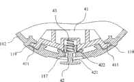
本实施例之四种插脚301、302、303、304的结构基本相同,如图9,均包括有绝缘座31和固装于该绝缘座31上的触脚32。结合图2,这些插脚30的绝缘座31分别套装于前述对应的导柱124上,使各插脚30可沿其导柱124自由纵向滑动伸缩,对应于底座12的底板121上设置有供各插脚伸出的通孔。同时,这些插脚30亦围绕前述中心转轴101周向分布,并随底座12同步转动。各插脚30的外侧面均设置有两导电触点33,利用该导电触点33可对应与插座模块20电连接。此外,于该插脚30的外侧面还设置有一弹性定位块34,该弹性定位块34位于前述两导电触点33之间,弹性定位块34的外侧端伸出绝缘座31外,弹性定位块34的内侧端抵于一压缩弹簧上,由该压缩弹簧提供其向外伸出的弹性作用力。结合图10和图7,对应于前述第二侧壁板112的内壁面上设置有沿插脚之伸出方向延伸的定位槽116,前述弹性定位块34嵌伸于该定位槽116内,实现该插脚30的旋转定位。The structures of the four
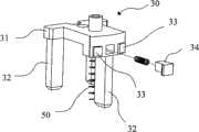
为实现将插脚30伸出壳体10外之工作位置的操作,如图3和图4,本实施例于上盖11之第二侧壁板112上设置有一定位滑槽117,该定位滑槽117平行于前述中心转轴101纵向延伸设置,并定位滑槽117横向贯穿第二侧壁板112,以及,于定位滑槽117上还纵向间距设置有加宽槽118。In order to realize the operation of protruding the
结合图3和图8,对应该定位滑槽117设置有可沿定位滑槽117自由滑动的滑移组件40,该滑移组件40包括有推块41、控制按键42和压缩弹簧45。该推块41紧贴于前述第二容置腔113之内壁面,并位于前述定位滑槽117的内侧,推块41的两横向侧端分别设置有一扣部411,对应于第二容置腔113之内壁面上设置有两纵向延伸的勾槽119,该扣部411卡入勾槽119中,使推块41可沿勾槽119纵向自由滑动。推块41滑动的过程中,由该推块41作用于插脚30之绝缘座31的顶面,以向下按压插脚30而将插脚30从壳体10中推出至其工作位置。该控制按键42横向嵌装于前述定位滑槽117中,控制按键117的内侧端抵推于该压缩弹簧43上并与推块41配合连接,使推块41与控制按键42同步移动,控制按键42的外侧端伸出壳体10外,方便人们操作该控制按键42以带动推块41于定位滑槽117中纵向滑动。以及,于控制按键42上设置有分别与定位滑槽117和加宽槽118的宽度相适配的第一颈部421和第二颈部422。控制按键42在纵向滑动的过程中,其第一颈部421于定位滑槽117上滑动,当其滑动到位时,其第二颈部422对应可卡入前述加宽槽118中,以实现控制按键42与推块41的滑动定位,使插脚30定位保持在其工作位置或隐藏位置。Referring to FIG. 3 and FIG. 8 , corresponding to the
相应的,为实现将插脚30缩回于壳体10内隐藏位置之操作,对应各插脚30需要配设有用于促使插脚30缩回其隐藏位置的复位机构,如图9,本实施例之复位机构采用压缩弹簧50,该复位弹簧50抵于插脚30之绝缘座31的底面,用于向上提供插脚30缩回壳体10内之隐藏位置的自动复位作用力。Correspondingly, in order to realize the operation of retracting the
藉此,由该推块41的滑动工作位置形成其可推出插脚30的功能区,结合图3和图10,该功能区内进一步设置有两平行间距设置的长条导电触片60,用于与插脚30上的两导电触点33导通电连接。该长条导电触片60嵌装于上盖11内壁面上的两条容置槽110中,同时,该两长条导电触片60的上端与插座模块20之间为常电连接。当其中一插脚30旋转至推块41下方的功能区时,该两导电触点33才分别与两长条导电触片60电连接,进而将该插脚30与插座模块20导通电连接,使该插脚30成为导电的有效插脚,其它插脚30则与插座模块断开电连接而处于断电安全模式。该两长条导电触片60的下端沿插脚30伸出方向延伸,在插脚30向外伸出滑动的整个过程中,插脚30上的两导电触点33可始终与长条导电触片60保持电接触。In this way, the sliding working position of the
详述本实施例的使用方法和工作原理如下:The usage method and working principle of this embodiment are described in detail as follows:
初始状态,如图1,该滑移组件10的推块41系位于定位滑槽117的最顶端之加宽槽118中,该四个插脚301、302、303、304均在复位弹簧50的作用下缩回于壳体10内之隐藏位置。这样电源转接器具有最小之空间体积,而便于携带和运输。In the initial state, as shown in Figure 1, the
使用时,用户需要轻轻地转动该底座12,带动所有插脚301、302、303、304一起随底座12同步转动,在转动的过程中选择所需要之规格插脚,当该需要使用之插脚旋转至推块41的功能区时,该插脚30上的弹性定位块34恰恰滑移至定位槽116中,使该插脚30获得在该功能区的旋转位移定位,以便下一步的操作。与此同时,该插脚30外侧设置的两导电触点33亦恰与该位置的两长条触片60抵触导通,进而使位于该功能区中的插脚30与插座20电连接。When in use, the user needs to turn the
接下来,用户可横向按压该控制按键42,使控制按键42的第一颈部421脱出加宽槽118后使第二颈部422沿定位滑槽117纵向向下滑动,在控制按键42向下滑动的过程中,随控制按键42同步移动的推块41便作用于该插脚30的上表面,而带动插脚30向下伸出,直至该控制按键42向下滑移至下方的加宽槽118时,如图4,用户可松开对控制按键42的按压,而使第一颈部421卡入加宽槽118中,将控制按键42定位在该档位,此时,该插脚30已伸出壳体10外处于其工作位置,可用于与适配之插座插接使用。Next, the user can press the
使用完后,用户同样按压该控制按键42后促使其沿定位滑槽117反向朝上滑动,推块41解除对插脚30的按压作用,此时在复位弹簧50的推力作用下,该插脚30会自动回缩于壳体内隐藏。After use, the user also presses the
综上所述,本发明的设计重点在于,其主要系通过将各插脚设置为可相对插座转动的底座中,然后于上盖上设置可将其中一插脚推出的滑移组件,因此用户通过转动底座即可选择性将所需要之规格的插脚旋移至滑移组件的功能区,然后利用该滑移组件沿定位滑槽的滑动来将所选择的插脚伸出进行插接使用,实现一种旋转选择推出式多国电源转接器,操作简便,且各插脚伸出十分顺畅,带来使用上的便利性。而且,其只有在插脚旋移至滑移组件的功能区时,该插脚上的导电触点才与长条导电触片导通连接进行导电,其余插脚均隐藏于壳体内并处于非导电状态,因此其仅能使单一插脚独自伸出导电,使用更为安全可靠。To sum up, the key point of the design of the present invention is that it mainly sets each pin in a base that can rotate relative to the socket, and then sets a sliding component on the upper cover that can push one of the pins out, so that the user can rotate The base can selectively rotate the pins of the required specifications to the functional area of the sliding component, and then use the sliding component to slide along the positioning chute to extend the selected pins for plugging, realizing a Rotate to select the push-out multi-country power adapter, which is easy to operate, and the prongs extend smoothly, bringing convenience to use. Moreover, only when the pin is rotated to the functional area of the sliding component, the conductive contact on the pin is conductively connected with the long conductive contact piece for conduction, and the rest of the pins are hidden in the housing and are in a non-conductive state. Therefore, only a single pin can be extended to conduct electricity independently, which is safer and more reliable in use.
以上所述,仅是本发明的较佳实施例而已,并非对本发明的技术范围作任何限制,故凡是依据本发明的技术实质对以上实施例所作的任何细微修改、等同变化与修饰,均仍属于本发明技术方案的范围内。The above descriptions are only preferred embodiments of the present invention, and do not limit the technical scope of the present invention in any way, so any minor modifications, equivalent changes and modifications made to the above embodiments according to the technical essence of the present invention are still valid. It belongs to the scope of the technical solutions of the present invention.
Claims (9)
Translated fromChinesePriority Applications (1)
| Application Number | Priority Date | Filing Date | Title |
|---|---|---|---|
| CN2010101838018ACN101872911B (en) | 2010-05-18 | 2010-05-18 | Rotary selection push-out type multinational power supply adapter |
Applications Claiming Priority (1)
| Application Number | Priority Date | Filing Date | Title |
|---|---|---|---|
| CN2010101838018ACN101872911B (en) | 2010-05-18 | 2010-05-18 | Rotary selection push-out type multinational power supply adapter |
Publications (2)
| Publication Number | Publication Date |
|---|---|
| CN101872911Atrue CN101872911A (en) | 2010-10-27 |
| CN101872911B CN101872911B (en) | 2012-11-07 |
Family
ID=42997647
Family Applications (1)
| Application Number | Title | Priority Date | Filing Date |
|---|---|---|---|
| CN2010101838018AExpired - Fee RelatedCN101872911B (en) | 2010-05-18 | 2010-05-18 | Rotary selection push-out type multinational power supply adapter |
Country Status (1)
| Country | Link |
|---|---|
| CN (1) | CN101872911B (en) |
Cited By (28)
| Publication number | Priority date | Publication date | Assignee | Title |
|---|---|---|---|---|
| WO2017080508A1 (en)* | 2015-11-11 | 2017-05-18 | 公牛集团有限公司 | Travel adapter |
| WO2017092214A1 (en)* | 2015-12-04 | 2017-06-08 | 深圳市和宏实业股份有限公司 | Portable converter |
| WO2017198770A1 (en) | 2016-05-20 | 2017-11-23 | Travel Blue Ltd. | Safe travel plug adapter |
| WO2017198798A1 (en) | 2016-05-20 | 2017-11-23 | Travel Blue Ltd. | Travel plug adapter that is easy to operate |
| EP3252884A1 (en) | 2016-06-01 | 2017-12-06 | Travel Blue Limited | Compact travelling plug |
| EP3316414A1 (en) | 2016-11-01 | 2018-05-02 | Travel Blue Limited | Travel adapter which can be securely grounded |
| EP3316422A1 (en) | 2016-11-01 | 2018-05-02 | Travel Blue Limited | Comfortable to operate travel adapter |
| EP3316419A1 (en) | 2016-10-31 | 2018-05-02 | Travel Blue Ltd. | Secure travel connector adapter |
| EP3316423A1 (en) | 2016-11-01 | 2018-05-02 | Travel Blue Limited | Transportable travel adapter |
| EP3316420A1 (en) | 2016-10-31 | 2018-05-02 | Travel Blue Ltd. | Easily operable travel connector adapter |
| EP3316421A1 (en) | 2016-11-01 | 2018-05-02 | Travel Blue Limited | Compact, groundable travel adapter |
| CN108206445A (en)* | 2018-01-19 | 2018-06-26 | 东莞欧陆电子有限公司 | A kind of more specification plug converters |
| TWI639283B (en) | 2017-08-08 | 2018-10-21 | 碩天科技股份有限公司 | Adapter and using method thereof |
| WO2018214591A1 (en)* | 2017-05-26 | 2018-11-29 | 广东百事泰电子商务股份有限公司 | Power socket capable of free replacement of plug |
| CN109390825A (en)* | 2017-08-08 | 2019-02-26 | 宁远县硕宁电子有限公司 | Adapter and its application method |
| EP3467964A1 (en)* | 2017-10-06 | 2019-04-10 | Powertech Industrial Co., Ltd. | Retractable plug device |
| EP3618200A1 (en) | 2018-09-01 | 2020-03-04 | Travel Blue Limited | Robust travel plug adapter |
| EP3618201A1 (en) | 2018-09-01 | 2020-03-04 | Travel Blue Limited | Universal connector |
| US10739323B2 (en) | 2017-10-17 | 2020-08-11 | Pierre Desjardins | Interconnecting detector |
| CN111682334A (en)* | 2019-09-17 | 2020-09-18 | 曾广莉 | A multi-way sliding small plug |
| WO2021009265A1 (en)* | 2019-07-15 | 2021-01-21 | Hyphenate Inc. | Multi-plug adapter |
| CN113161805A (en)* | 2020-04-13 | 2021-07-23 | 东莞市佳旅电器有限公司 | Telescopic mechanism of European-style plug of power converter with grounding pin |
| CN113196592A (en)* | 2018-12-21 | 2021-07-30 | 世界连接股份公司 | Travel adapter and kit including the same |
| CN114784551A (en)* | 2022-03-01 | 2022-07-22 | 浙江宏恩装饰工程有限公司 | Interior decoration inserts with hiding |
| CN114865413A (en)* | 2022-06-02 | 2022-08-05 | 杭州绿辉照明科技有限公司 | Battery package interface conversion adapter |
| CN114914750A (en)* | 2020-10-29 | 2022-08-16 | Oppo广东移动通信有限公司 | Power adapter |
| CN116706631A (en)* | 2023-07-31 | 2023-09-05 | 珠海市钛芯动力科技有限公司 | Conversion plug |
| WO2024120392A1 (en)* | 2022-12-06 | 2024-06-13 | 品威电子国际股份有限公司 | Adapter head, adapter base and adapter assembly |
Citations (5)
| Publication number | Priority date | Publication date | Assignee | Title |
|---|---|---|---|---|
| US20070293072A1 (en)* | 2005-04-28 | 2007-12-20 | Sze Hung To Honton | 4 in 1 travel adaptor |
| CN201112759Y (en)* | 2007-07-13 | 2008-09-10 | 英嘉国际有限公司 | Power supply converter with safe protecting cover |
| US7445513B1 (en)* | 2007-10-13 | 2008-11-04 | Dongguan Ahoku Electronic Company | Power adaptor equipped with multi-plug and multi-outlet |
| CN201153181Y (en)* | 2007-10-19 | 2008-11-19 | 郎跃辉 | Universal power supply adapter |
| CN201327936Y (en)* | 2008-12-17 | 2009-10-14 | 英嘉国际有限公司 | Rotary single push handle power supply converter |
- 2010
- 2010-05-18CNCN2010101838018Apatent/CN101872911B/ennot_activeExpired - Fee Related
Patent Citations (5)
| Publication number | Priority date | Publication date | Assignee | Title |
|---|---|---|---|---|
| US20070293072A1 (en)* | 2005-04-28 | 2007-12-20 | Sze Hung To Honton | 4 in 1 travel adaptor |
| CN201112759Y (en)* | 2007-07-13 | 2008-09-10 | 英嘉国际有限公司 | Power supply converter with safe protecting cover |
| US7445513B1 (en)* | 2007-10-13 | 2008-11-04 | Dongguan Ahoku Electronic Company | Power adaptor equipped with multi-plug and multi-outlet |
| CN201153181Y (en)* | 2007-10-19 | 2008-11-19 | 郎跃辉 | Universal power supply adapter |
| CN201327936Y (en)* | 2008-12-17 | 2009-10-14 | 英嘉国际有限公司 | Rotary single push handle power supply converter |
Cited By (55)
| Publication number | Priority date | Publication date | Assignee | Title |
|---|---|---|---|---|
| US10686285B2 (en) | 2015-11-11 | 2020-06-16 | Gongniu Group Co., Ltd. | Travel adapter with integrated plugs meeting different plug standards |
| WO2017080508A1 (en)* | 2015-11-11 | 2017-05-18 | 公牛集团有限公司 | Travel adapter |
| WO2017092214A1 (en)* | 2015-12-04 | 2017-06-08 | 深圳市和宏实业股份有限公司 | Portable converter |
| WO2017198770A1 (en) | 2016-05-20 | 2017-11-23 | Travel Blue Ltd. | Safe travel plug adapter |
| WO2017198798A1 (en) | 2016-05-20 | 2017-11-23 | Travel Blue Ltd. | Travel plug adapter that is easy to operate |
| EP3252884A1 (en) | 2016-06-01 | 2017-12-06 | Travel Blue Limited | Compact travelling plug |
| WO2017207096A1 (en) | 2016-06-01 | 2017-12-07 | Travel Blue Ltd., Magnolia House | Compact travel plug |
| CN109314356B (en)* | 2016-06-01 | 2021-02-12 | 蓝旅有限公司 | Simple conversion plug |
| EP3252884B1 (en)* | 2016-06-01 | 2023-07-26 | Travel Blue Limited | Compact travelling plug |
| CN109314356A (en)* | 2016-06-01 | 2019-02-05 | 蓝旅有限公司 | Succinct changeover plug |
| EP3316419A1 (en) | 2016-10-31 | 2018-05-02 | Travel Blue Ltd. | Secure travel connector adapter |
| EP3316420A1 (en) | 2016-10-31 | 2018-05-02 | Travel Blue Ltd. | Easily operable travel connector adapter |
| WO2018083125A1 (en) | 2016-11-01 | 2018-05-11 | Travel Blue Ltd. | Compact, groundable travel plug adapter |
| EP3316421A1 (en) | 2016-11-01 | 2018-05-02 | Travel Blue Limited | Compact, groundable travel adapter |
| WO2018083131A1 (en) | 2016-11-01 | 2018-05-11 | Travel Blue Ltd. | Transport-safe travel plug adapter |
| WO2018083129A1 (en) | 2016-11-01 | 2018-05-11 | Travel Blue Ltd. | Conveniently operable travel plu adapter |
| WO2018083134A1 (en) | 2016-11-01 | 2018-05-11 | Travel Blue Ltd. | Travel plug adapter that can be safely grounded |
| EP3316414A1 (en) | 2016-11-01 | 2018-05-02 | Travel Blue Limited | Travel adapter which can be securely grounded |
| EP3316422A1 (en) | 2016-11-01 | 2018-05-02 | Travel Blue Limited | Comfortable to operate travel adapter |
| EP3316423A1 (en) | 2016-11-01 | 2018-05-02 | Travel Blue Limited | Transportable travel adapter |
| WO2018214591A1 (en)* | 2017-05-26 | 2018-11-29 | 广东百事泰电子商务股份有限公司 | Power socket capable of free replacement of plug |
| CN109390825A (en)* | 2017-08-08 | 2019-02-26 | 宁远县硕宁电子有限公司 | Adapter and its application method |
| CN109390825B (en)* | 2017-08-08 | 2020-04-10 | 宁远县硕宁电子有限公司 | Adapter and method of use |
| TWI639283B (en) | 2017-08-08 | 2018-10-21 | 碩天科技股份有限公司 | Adapter and using method thereof |
| EP3467964A1 (en)* | 2017-10-06 | 2019-04-10 | Powertech Industrial Co., Ltd. | Retractable plug device |
| US10739323B2 (en) | 2017-10-17 | 2020-08-11 | Pierre Desjardins | Interconnecting detector |
| CN108206445A (en)* | 2018-01-19 | 2018-06-26 | 东莞欧陆电子有限公司 | A kind of more specification plug converters |
| CN108206445B (en)* | 2018-01-19 | 2024-01-30 | 东莞欧陆电子有限公司 | Multi-specification plug converter |
| CN110875560A (en)* | 2018-09-01 | 2020-03-10 | 蓝旅有限公司 | Universal connector |
| EP3618201A1 (en) | 2018-09-01 | 2020-03-04 | Travel Blue Limited | Universal connector |
| DE102018006922A1 (en)* | 2018-09-01 | 2020-03-05 | Travel Blue Limited | Robust travel plug adapter |
| DE102018006922B4 (en)* | 2018-09-01 | 2020-04-09 | Travel Blue Limited | Robust travel plug adapter |
| CN110875560B (en)* | 2018-09-01 | 2021-11-16 | 蓝旅有限公司 | Universal connector |
| EP3618200A1 (en) | 2018-09-01 | 2020-03-04 | Travel Blue Limited | Robust travel plug adapter |
| CN113196592B (en)* | 2018-12-21 | 2023-11-17 | 世界连接股份公司 | Travel adapters and kits including travel adapters |
| CN113196592A (en)* | 2018-12-21 | 2021-07-30 | 世界连接股份公司 | Travel adapter and kit including the same |
| US12255426B2 (en) | 2019-07-15 | 2025-03-18 | Hyphenate Inc. | Adapter for travel with multi-plug functionality featuring reduced dimension |
| WO2021009265A1 (en)* | 2019-07-15 | 2021-01-21 | Hyphenate Inc. | Multi-plug adapter |
| US20220320809A1 (en)* | 2019-07-15 | 2022-10-06 | Hyphenate Inc. | Multi-plug adapter |
| WO2021052093A1 (en)* | 2019-09-17 | 2021-03-25 | 曾广莉 | Multi-path sliding small plug |
| CN111682334B (en)* | 2019-09-17 | 2022-05-31 | 东莞市佳旅电器有限公司 | Multi-way sliding type small plug |
| KR200498016Y1 (en)* | 2019-09-17 | 2024-05-22 | 둥관 베스트 트래블 일렉트로닉스 컴퍼니 리미티드 | Multipass sliding small plug |
| KR20220000642U (en)* | 2019-09-17 | 2022-03-17 | 둥관 베스트 트래블 일렉트로닉스 컴퍼니 리미티드 | Multipass Sliding Small Plug |
| WO2021051470A1 (en)* | 2019-09-17 | 2021-03-25 | 东莞市佳旅电器有限公司 | Multi-path sliding small plug |
| CN111682334A (en)* | 2019-09-17 | 2020-09-18 | 曾广莉 | A multi-way sliding small plug |
| EP4020720A4 (en)* | 2019-09-17 | 2023-08-30 | Zeng, Guangli | MULTIPLE SLIDING SMALL PLUG |
| AU2020348701B2 (en)* | 2019-09-17 | 2023-12-14 | Guangli ZENG | Small sliding multiple plug |
| CN113161805A (en)* | 2020-04-13 | 2021-07-23 | 东莞市佳旅电器有限公司 | Telescopic mechanism of European-style plug of power converter with grounding pin |
| CN114914750A (en)* | 2020-10-29 | 2022-08-16 | Oppo广东移动通信有限公司 | Power adapter |
| CN114914750B (en)* | 2020-10-29 | 2024-12-17 | Oppo广东移动通信有限公司 | Power adapter |
| CN114784551A (en)* | 2022-03-01 | 2022-07-22 | 浙江宏恩装饰工程有限公司 | Interior decoration inserts with hiding |
| CN114865413A (en)* | 2022-06-02 | 2022-08-05 | 杭州绿辉照明科技有限公司 | Battery package interface conversion adapter |
| WO2024120392A1 (en)* | 2022-12-06 | 2024-06-13 | 品威电子国际股份有限公司 | Adapter head, adapter base and adapter assembly |
| CN116706631A (en)* | 2023-07-31 | 2023-09-05 | 珠海市钛芯动力科技有限公司 | Conversion plug |
| CN116706631B (en)* | 2023-07-31 | 2023-12-22 | 珠海市钛芯动力科技有限公司 | Conversion plug |
Also Published As
| Publication number | Publication date |
|---|---|
| CN101872911B (en) | 2012-11-07 |
Similar Documents
| Publication | Publication Date | Title |
|---|---|---|
| CN101872911A (en) | Rotary selection push-out type multinational power supply adapter | |
| CN110289532B (en) | Adapter joint | |
| CN105206993B (en) | The converter of the scalable storage of plug | |
| CN203056216U (en) | Pop-up wall socket | |
| CN105576408B (en) | Converter with button selection function | |
| CN111355089B (en) | Waterproof and anti-electric shock socket and plug | |
| CN100433470C (en) | Multi-country universal electric adaptor | |
| CN208336645U (en) | Automatic scalable multinational intelligent charger | |
| CN105261907B (en) | A kind of telescopic earth polar latch converter | |
| CN201061054Y (en) | Multinational electricity adapter plug | |
| CN204966838U (en) | Scalable converter of accomodating of plug | |
| CN110011147A (en) | A plug-in convertible plug | |
| CN204966897U (en) | Telescopic terrestrial pole bolt converter | |
| CN111628346B (en) | Power strip and plug | |
| CN116706631B (en) | Conversion plug | |
| CN201153181Y (en) | Universal power supply adapter | |
| CN202352919U (en) | Pop-up power supply socket | |
| CN211508054U (en) | Charger for multinational plug | |
| CN209516159U (en) | A kind of folding plug | |
| CN211952955U (en) | Electric heater | |
| CN210517252U (en) | Adapter | |
| CN209516255U (en) | A kind of foldable changeover plug of pin | |
| GB2484145A (en) | Universal electric adapter | |
| CN204441656U (en) | Attaching plug | |
| CN203747195U (en) | Two-in-one card holder |
Legal Events
| Date | Code | Title | Description |
|---|---|---|---|
| C06 | Publication | ||
| PB01 | Publication | ||
| C10 | Entry into substantive examination | ||
| SE01 | Entry into force of request for substantive examination | ||
| C14 | Grant of patent or utility model | ||
| GR01 | Patent grant | ||
| C17 | Cessation of patent right | ||
| CF01 | Termination of patent right due to non-payment of annual fee | Granted publication date:20121107 Termination date:20130518 |