CN101872044B - Fiber optic distribution cables and structures therefor - Google Patents
Fiber optic distribution cables and structures thereforDownload PDFInfo
- Publication number
- CN101872044B CN101872044BCN2010101532318ACN201010153231ACN101872044BCN 101872044 BCN101872044 BCN 101872044BCN 2010101532318 ACN2010101532318 ACN 2010101532318ACN 201010153231 ACN201010153231 ACN 201010153231ACN 101872044 BCN101872044 BCN 101872044B
- Authority
- CN
- China
- Prior art keywords
- distribution
- fiber optic
- fiber
- optical fibers
- optic distribution
- Prior art date
- Legal status (The legal status is an assumption and is not a legal conclusion. Google has not performed a legal analysis and makes no representation as to the accuracy of the status listed.)
- Expired - Fee Related
Links
- 238000009826distributionMethods0.000titleclaimsabstractdescription456
- 239000000835fiberSubstances0.000titleclaimsabstractdescription314
- 239000013307optical fiberSubstances0.000claimsabstractdescription139
- 230000001681protective effectEffects0.000claimsabstract7
- 230000007704transitionEffects0.000claimsdescription35
- 238000007789sealingMethods0.000claimsdescription25
- XLYOFNOQVPJJNP-UHFFFAOYSA-NwaterSubstancesOXLYOFNOQVPJJNP-UHFFFAOYSA-N0.000claimsdescription6
- 238000000926separation methodMethods0.000claimsdescription2
- 230000008961swellingEffects0.000claims4
- 238000001035dryingMethods0.000claims2
- 238000000034methodMethods0.000abstractdescription48
- 238000004519manufacturing processMethods0.000abstractdescription14
- 238000010276constructionMethods0.000abstractdescription2
- 230000002401inhibitory effectEffects0.000abstract1
- 239000011241protective layerSubstances0.000description45
- 239000000463materialSubstances0.000description38
- 238000005520cutting processMethods0.000description37
- 230000003287optical effectEffects0.000description21
- 230000008569processEffects0.000description14
- 239000010410layerSubstances0.000description11
- 238000005452bendingMethods0.000description9
- 238000013461designMethods0.000description9
- 230000000712assemblyEffects0.000description7
- 238000000429assemblyMethods0.000description7
- 238000004891communicationMethods0.000description7
- RYGMFSIKBFXOCR-UHFFFAOYSA-NCopperChemical compound[Cu]RYGMFSIKBFXOCR-UHFFFAOYSA-N0.000description6
- 230000004323axial lengthEffects0.000description6
- 239000006260foamSubstances0.000description6
- 238000003306harvestingMethods0.000description6
- 230000006835compressionEffects0.000description5
- 238000007906compressionMethods0.000description5
- 229910052802copperInorganic materials0.000description5
- 239000010949copperSubstances0.000description5
- 230000008878couplingEffects0.000description5
- 238000010168coupling processMethods0.000description5
- 238000005859coupling reactionMethods0.000description5
- 230000001012protectorEffects0.000description5
- 239000003566sealing materialSubstances0.000description5
- 239000004831Hot glueSubstances0.000description4
- 238000007796conventional methodMethods0.000description4
- -1fishing lineSubstances0.000description4
- 238000004078waterproofingMethods0.000description4
- 239000004519greaseSubstances0.000description3
- 238000009434installationMethods0.000description3
- 239000002184metalSubstances0.000description3
- 229910052751metalInorganic materials0.000description3
- 230000007935neutral effectEffects0.000description3
- 229920001296polysiloxanePolymers0.000description3
- 239000004810polytetrafluoroethyleneSubstances0.000description3
- 229920001343polytetrafluoroethylenePolymers0.000description3
- 239000000243solutionSubstances0.000description3
- 239000000853adhesiveSubstances0.000description2
- 230000001070adhesive effectEffects0.000description2
- 239000002131composite materialSubstances0.000description2
- 239000003292glueSubstances0.000description2
- 238000002347injectionMethods0.000description2
- 239000007924injectionSubstances0.000description2
- 238000012986modificationMethods0.000description2
- 230000004048modificationEffects0.000description2
- 239000011253protective coatingSubstances0.000description2
- 230000008439repair processEffects0.000description2
- 238000003466weldingMethods0.000description2
- 229920000742CottonPolymers0.000description1
- 229920000271Kevlar®Polymers0.000description1
- 239000004677NylonSubstances0.000description1
- 229920005830Polyurethane FoamPolymers0.000description1
- 229910000831SteelInorganic materials0.000description1
- 238000013459approachMethods0.000description1
- 239000004760aramidSubstances0.000description1
- 229920003235aromatic polyamidePolymers0.000description1
- 230000009286beneficial effectEffects0.000description1
- 230000008901benefitEffects0.000description1
- 230000005540biological transmissionEffects0.000description1
- 230000015572biosynthetic processEffects0.000description1
- 230000005465channelingEffects0.000description1
- 238000005253claddingMethods0.000description1
- 239000004020conductorSubstances0.000description1
- KAATUXNTWXVJKI-UHFFFAOYSA-NcypermethrinChemical compoundCC1(C)C(C=C(Cl)Cl)C1C(=O)OC(C#N)C1=CC=CC(OC=2C=CC=CC=2)=C1KAATUXNTWXVJKI-UHFFFAOYSA-N0.000description1
- 238000006073displacement reactionMethods0.000description1
- 230000000694effectsEffects0.000description1
- 230000007613environmental effectEffects0.000description1
- 238000001125extrusionMethods0.000description1
- 239000011152fibreglassSubstances0.000description1
- 238000013023gasketingMethods0.000description1
- 238000010438heat treatmentMethods0.000description1
- 238000003780insertionMethods0.000description1
- 230000037431insertionEffects0.000description1
- 238000011900installation processMethods0.000description1
- 230000001788irregularEffects0.000description1
- 239000012948isocyanateSubstances0.000description1
- 150000002513isocyanatesChemical class0.000description1
- 239000004761kevlarSubstances0.000description1
- 239000003550markerSubstances0.000description1
- 239000007769metal materialSubstances0.000description1
- 229920001778nylonPolymers0.000description1
- 239000004033plasticSubstances0.000description1
- 229920003023plasticPolymers0.000description1
- 239000002985plastic filmSubstances0.000description1
- 229920000728polyesterPolymers0.000description1
- 239000004848polyfunctional curativeSubstances0.000description1
- 229920000642polymerPolymers0.000description1
- 229920005862polyolPolymers0.000description1
- 150000003077polyolsChemical class0.000description1
- 239000011496polyurethane foamSubstances0.000description1
- 238000012545processingMethods0.000description1
- 230000000644propagated effectEffects0.000description1
- 230000000246remedial effectEffects0.000description1
- 239000011347resinSubstances0.000description1
- 229920005989resinPolymers0.000description1
- 238000010008shearingMethods0.000description1
- 239000010959steelSubstances0.000description1
- 238000003860storageMethods0.000description1
- 238000012360testing methodMethods0.000description1
- 238000011144upstream manufacturingMethods0.000description1
Images


Classifications
- G—PHYSICS
- G02—OPTICS
- G02B—OPTICAL ELEMENTS, SYSTEMS OR APPARATUS
- G02B6/00—Light guides; Structural details of arrangements comprising light guides and other optical elements, e.g. couplings
- G02B6/44—Mechanical structures for providing tensile strength and external protection for fibres, e.g. optical transmission cables
- G02B6/4439—Auxiliary devices
- G02B6/4471—Terminating devices ; Cable clamps
- G02B6/4472—Manifolds
- G02B6/4475—Manifolds with provision for lateral branching
- G—PHYSICS
- G02—OPTICS
- G02B—OPTICAL ELEMENTS, SYSTEMS OR APPARATUS
- G02B6/00—Light guides; Structural details of arrangements comprising light guides and other optical elements, e.g. couplings
- G02B6/44—Mechanical structures for providing tensile strength and external protection for fibres, e.g. optical transmission cables
- G02B6/4439—Auxiliary devices
- G02B6/444—Systems or boxes with surplus lengths
- G02B6/4441—Boxes
- G02B6/44515—Fibre drop terminals with surplus length
Landscapes
- Physics & Mathematics (AREA)
- General Physics & Mathematics (AREA)
- Optics & Photonics (AREA)
- Light Guides In General And Applications Therefor (AREA)
Abstract
Description
Translated fromChinese技术领域technical field
本发明总的来说涉及一种光纤分配缆线,该光纤分配缆线的制造方法,及用于它的工具和成套工具。更具体地说,本发明涉及一种用于在例如光纤到户或街头应用(FTTx)中向用户分配光纤的光纤分配缆线,该光纤分配缆线的制造方法,及工具和成套工具。The present invention generally relates to a fiber optic distribution cable, a method of making the fiber optic distribution cable, and tools and kits therefor. More particularly, the present invention relates to a fiber optic distribution cable for distributing fiber to subscribers in, for example, fiber to the home or street applications (FTTx), a method of manufacturing the fiber optic distribution cable, and tools and kits.
背景技术Background technique
通信网络用于传输诸如声音、视频、数据传输等的各种信号。传统的通信网络利用铜线电缆传输信息和数据。但是,铜质电缆具有缺点,因为它们大,重并且合理的电缆直径只能传输相对有限的数据量。因此,在长距离通信网络线路中光缆取代了大部分铜质电缆,从而为长距离线路提供较大带宽的容量。但是,大多数通信网路在中心局的用户侧仍然使用铜质电缆用于分配目的和/或分出线路。换句话说,由于通信网络中铜质电缆的原因,用户只能获得有限的可用带宽量。换句话说,铜质电缆是阻止用户充分地利用长距离线路光纤的相对高带宽容量的瓶颈。Communication networks are used to transmit various signals such as voice, video, data transmission, and the like. Traditional communication networks use copper wire cables to transmit information and data. However, copper cables have disadvantages in that they are large, heavy and with reasonable cable diameters can only transmit relatively limited amounts of data. Therefore, optical cables replace most copper cables in long-distance communication network lines, thereby providing larger bandwidth capacity for long-distance lines. However, most communication networks still use copper cables for distribution purposes and/or drop lines at the customer side of the central office. In other words, users only get a limited amount of available bandwidth due to the copper cables in the communication network. In other words, copper cables are the bottleneck that prevents users from taking full advantage of the relatively high bandwidth capacity of fiber optics on long-distance lines.
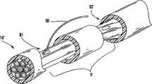
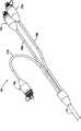
当光纤更深入地用于通信网络中时,用户将能够获得增加的带宽。但是,从光缆向用户分配光纤存在的确切障碍是其是困难和昂贵的。例如,一种获取从光缆中分配的光纤的传统方法需要在缆线外壳中设置相对长的裂口以获取适当长度的光纤。图1描述的是在光纤外壳中具有裂口长度BL的裂口B的光缆10。裂口长度BL取决于用于获取工序的工艺所需的光纤OF的长度。例如,如果技术工人需要30厘米的分配光纤OF用于获取工序,则裂口长度BL具有稍长的长度,例如,35厘米,以在缆线外壳外侧提供30厘米的光纤OF。更特别地,选择分配所需的光纤并将其在裂口B的下游附近切断,然后配置将其从裂口B的上游附近的光缆引出,从而给技术工人提供所需的长度的光纤OF。这种方法的一个缺点是裂口长度BL相对较长并且破坏了缆线外壳所提供的保护。换句话说,裂口B必须被关闭和/或密封以便提供适当的保护,这需要相对大的保护层,该保护层是大体积、笨重和/或僵硬的。因此,分配光缆在分配位置太大和/或僵硬,从而即使可能,但在安装期间难以通过套、管等设置光缆分配的有效路径。As fiber optics are used deeper into communication networks, users will be able to obtain increased bandwidth. However, a definite obstacle to distributing fiber from cable to subscribers is that it is difficult and expensive. For example, one conventional method of accessing optical fiber dispensed from a fiber optic cable requires relatively long slits in the cable jacket to access the appropriate length of optical fiber. Figure 1 depicts a fiber
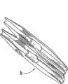
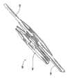
另一种获取从光缆中分配的光纤的传统方法需要在两个位置裂开缆线外壳,如图2所示。图2描述的光缆10’具有分开有效距离D的第一缆线外壳裂口B1和第二(即下游的)缆线外壳裂口B2。例如,缆线外壳裂口B1和B2之间的通常距离D大约为30厘米。然后,选择向用户分配所需的光纤OF并将其在第二缆线外壳裂口B2的位置切断。接下来,在第二缆线外壳裂口B2位置处将被切断的光纤OF定位在第一缆线外壳裂口B 1处并且然后将其拉向第一缆线外壳裂口B1直到从那儿突出,如图所示。简单地说,用于分配的光纤OF必须被定位两次(在每个外壳裂口B1和B2各一次)并且从第一缆线外壳裂口B1伸出的光纤OF的长度取决于缆线外壳裂口B1和B2之间的距离D。通常,例如通过过模制模制或利用热缩管闭合缆线外壳裂口B1和B2以提供环境保护。因此,这种获取和提供用于分配的光纤的传统工序是费时的,可能损害光纤,和/或在密封缆线外壳裂口之后产生相对大的突起。Another traditional method of accessing the fiber dispensed from the cable requires splitting the cable jacket at two locations, as shown in Figure 2. Figure 2 depicts a fiber optic cable 10' having a first cable jacket breach B1 and a second (i.e., downstream) cable jacket breach B2 separated by an effective distance D. For example, a typical distance D between the cable jacket breaches B1 and B2 is about 30 centimeters. Then, select and distribute the required optical fiber OF to the user and cut it at the position of the second cable jacket breach B2. Next, the severed optical fiber OF is positioned at the first cable jacket breach B1 at the position of the second cable jacket breach B2 and then pulled toward the first cable jacket breach B1 until it protrudes therefrom, as shown in FIG. shown. Briefly, the optical fiber OF for distribution must be positioned twice (once in each housing breach B1 and B2) and the length of the optical fiber OF protruding from the first cable housing breach B1 depends on the cable housing breach B1 and the distance D between B2. Typically, the cable jacket breaches B1 and B2 are closed to provide environmental protection, eg by overmolding or with heat shrink tubing. Thus, such conventional procedures for obtaining and providing optical fibers for distribution are time consuming, can damage the optical fibers, and/or create relatively large protrusions after sealing the cable jacket breach.
因此,希望获得一种具有顺利的安装工艺的分配光缆的低成本解决方法。此外,解决方法同样需要提供相对小的印记,灵活的分配位置,容易的维修/修理,和/或连接的多样性。另外,分配光缆组件的可靠性和坚固性需要抵挡严酷的外部环境。本发明提供一种可靠和低成本的解决方法,该解决方法能够工艺顺利地以相对小和灵活的分配位置从光缆向用户分配光纤。Therefore, a low-cost solution for distribution cables with a smooth installation process is desired. In addition, solutions also need to provide relatively small footprint, flexible distribution locations, easy servicing/repair, and/or connectivity versatility. Additionally, the reliability and robustness of distribution cable assemblies needs to withstand harsh external environments. The present invention provides a reliable and low-cost solution that enables the smooth distribution of optical fibers from optical cables to subscribers at relatively small and flexible distribution locations.
发明内容Contents of the invention
本发明的一个方面涉及一种向用户引导光纤的光纤分配缆线。该光线分配缆线包括保护层内的多根光纤和分配光纤。该分配光纤是光纤分配缆线的多个光纤中的一个,并且该分配光纤在保护层的用于向用户分配的获取位置处向外呈现。该获取位置具有长度AL并且从光纤分配缆线移出的分配光纤具有分配光纤长度DOFL,其中该分配光纤长度是大约5/4AL或更长。One aspect of the invention relates to a fiber optic distribution cable that guides fiber to a user. The optical distribution cable includes a plurality of optical fibers and distribution optical fibers within a protective layer. The distribution optical fiber is one of the plurality of optical fibers of the fiber optic distribution cable, and the distribution optical fiber is presented outwardly at an access location of the protective layer for distribution to users. The access location has a length AL and the distribution fiber removed from the fiber optic distribution cable has a distribution fiber length DOFL, wherein the distribution fiber length is about 5/4 AL or longer.
本发明的另一个方面涉及一种光纤分配缆线,包括多根光纤,保护层,分配光纤和分界点。该分配光纤是光纤分配缆线的多个光纤中的一个,并且该分配光纤在保护层的获取位置处向外呈现。分界点大约被设置在该分配光纤的一部分周围以阻止该分配光纤的运动。换句话说,该分界点阻止该分配光纤以活塞方式进入或离开光纤分配缆线。Another aspect of the invention relates to an optical fiber distribution cable comprising a plurality of optical fibers, a protective layer, distribution optical fibers and a demarcation point. The distribution optical fiber is one of the plurality of optical fibers of the fiber optic distribution cable, and the distribution optical fiber presents outwardly at the access location of the protective layer. A demarcation point is positioned about a portion of the distribution fiber to prevent movement of the distribution fiber. In other words, the demarcation point prevents the distribution fiber from pistonically entering or exiting the fiber optic distribution cable.
本发明的再一个实施例涉及一种光纤分配缆线,包括多根光纤,保护层,至少一根分配光纤,指引管(indexing tube)和限度管(tether tube)。该至少一根分配光纤选自该光纤分配光缆的一根光纤并从保护层的获取位置突出。该限度管大约被设置在该至少一根分配光纤的一部分上以保护该至少一根分配光纤。同样,该限度管相对于指引管被附着在预定位置上,从而在分配光纤上获取光纤长度。另外,通过工艺能够在光纤分配缆线上执行其它可能或可能不需要其它部件的步骤。例如,过渡管(transition tube)可以在分配光纤上滑行以保护该分配光纤。Yet another embodiment of the present invention relates to an optical fiber distribution cable comprising a plurality of optical fibers, a protective layer, at least one distribution optical fiber, an indexing tube and a tether tube. The at least one distribution optical fiber is selected from one optical fiber of the fiber optic distribution cable and protrudes from the access location of the protective layer. The confinement tube is disposed approximately over a portion of the at least one distribution optical fiber to protect the at least one distribution optical fiber. Also, the confinement tube is attached at a predetermined position relative to the guide tube to obtain fiber lengths on the distribution fiber. Additionally, other steps that may or may not require other components can be performed on the fiber optic distribution cable by the process. For example, a transition tube can be slid over the distribution fiber to protect the distribution fiber.
应该理解的是上述对本发明的实施例的一般性描述和下述对本发明的实施例的详细描述都旨在提供一种理解本发明所要求的本质和特征的综述或框架。包括附图以提供对本发明的进一步理解,而且将其结合到本说明书中并构成本说明书的一部分。附图说明本发明的不同实施例,并且和说明书一起来解释本发明的原理和工作。It should be understood that both the above general description of the embodiments of the invention and the following detailed description of the embodiments of the invention are intended to provide an overview or framework for understanding the nature and characteristics of the invention. The accompanying drawings are included to provide a further understanding of the invention, and are incorporated into and constitute a part of this specification. The drawings illustrate various embodiments of the invention, and together with the description serve to explain the principles and operation of the invention.
附图说明Description of drawings
图1是在光缆的相对大的长度上开口以获取用于光纤分配的合适长度的光纤的一种传统方法的透视图。Figure 1 is a perspective view of one conventional method of opening a relatively large length of fiber optic cable to obtain a suitable length of fiber for fiber distribution.
图2是在光缆的两个位置上开口以获取用于光纤分配的合适长度的光纤的另一种传统方法的透视图。Fig. 2 is a perspective view of another conventional method of opening a fiber optic cable at two locations to obtain a suitable length of fiber for fiber distribution.
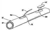
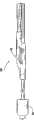
图3是根据本发明的一般光纤分配缆线的透视图,其示出了在光纤分配缆线之内的切断位置切断分配光纤之后,从该光纤分配缆线的第一获取位置突出的分配光纤。3 is a perspective view of a typical fiber optic distribution cable according to the present invention showing the distribution fiber protruding from a first access location of the fiber optic distribution cable after the distribution fiber has been severed at a cut location within the fiber optic distribution cable .
图3a-3g是图3的一般光纤分配缆线代表的优选光纤分配缆线的截面图。3a-3g are cross-sectional views of a preferred fiber optic distribution cable represented by the general fiber optic distribution cable of FIG.
图4是根据本发明用于制造图3的光纤分配缆线的方法的步骤的流程图。4 is a flowchart of the steps of a method for manufacturing the fiber optic distribution cable of FIG. 3 in accordance with the present invention.
图5和5a-5f分别是根据本发明的用于切断光纤分配缆线之内的光纤的说明性工具(explanatory tool)及其变型的透视图。5 and 5a-5f are perspective views, respectively, of an explanatory tool and variations thereof for severing optical fibers within a fiber optic distribution cable according to the present invention.
图6a描述的是图5工具,该工具具有在图3的光纤分配缆线切断之前的多个分配光纤周围成环形的切断元件。Fig. 6a depicts the tool of Fig. 5 having a cutting element looped around a plurality of distribution fibers prior to cutting of the fiber optic distribution cable of Fig. 3 .
图6b描述的是图5的工具,该工具被插入到图3的光纤分配缆线之内,用于在光纤分配缆线之内的切断位置切断分配光纤。Figure 6b depicts the tool of Figure 5 inserted into the fiber optic distribution cable of Figure 3 for severing the distribution fiber at a cut location within the fiber optic distribution cable.
图6c描述的是图3的光纤分配光缆以及根据本发明的一套零件的分解图。Figure 6c depicts an exploded view of the fiber optic distribution cable of Figure 3 and a set of parts according to the present invention.
图6d是图6c的帽的截面图。Figure 6d is a cross-sectional view of the cap of Figure 6c.
图6e是图3的光纤分配缆线以及根据本发明组装在其上的图6c的一套零件的透视图。Figure 6e is a perspective view of the fiber optic distribution cable of Figure 3 and the kit of parts of Figure 6c assembled thereon in accordance with the present invention.
图6f描述的是在利用合适的材料将帽保护好之后的图6e的组件。Figure 6f depicts the assembly of Figure 6e after the cap has been protected with a suitable material.
图6g描述的是图5中的工具,该工具在切断位置切断分配光纤之前被定位在一部分光纤带周围以沿着该光纤带的长度劈开该光纤带。Figure 6g depicts the tool of Figure 5 positioned around a portion of the fiber ribbon to cleave the fiber ribbon along its length prior to severing the distribution fiber at the cut position.
图6h是图3的具有根据本发明的可替换的帽构造的光纤分配缆线的透视图;Figure 6h is a perspective view of the fiber optic distribution cable of Figure 3 having an alternative cap configuration according to the present invention;
图6i是根据本发明的具有设置在分配光纤上的分界点的另一个光纤分配缆线。Figure 6i is another fiber optic distribution cable having a demarcation point disposed on a distribution fiber in accordance with the present invention.
图7是根据本发明的光纤分配缆线组件的侧视图。Figure 7 is a side view of a fiber optic distribution cable assembly in accordance with the present invention.
图8是根据本发明的图7的光纤分配缆线组件的分解图。Figure 8 is an exploded view of the fiber optic distribution cable assembly of Figure 7 in accordance with the present invention.
图9是沿着线9-9的图7的光纤分配缆线组件的截面图。9 is a cross-sectional view of the fiber optic distribution cable assembly of FIG. 7 along line 9-9.
图10是沿着线10-10的图7的光纤分配缆线组件的另一个截面图,而图10a是图10的截面图的一部分视图。10 is another cross-sectional view of the fiber optic distribution cable assembly of FIG. 7 along line 10-10, and FIG. 10a is a partial view of the cross-sectional view of FIG.
图11是沿着线11-11的图7的光纤分配缆线组件的另一个截面图。11 is another cross-sectional view of the fiber optic distribution cable assembly of FIG. 7 along line 11-11.
图12-16是示出不同阶段的图7的分配缆线组件的部分结构的透视图。12-16 are perspective views showing portions of the distribution cable assembly of Fig. 7 in various stages.
图17是根据本发明的包括套圈的另一种光纤分配缆线的透视图。Figure 17 is a perspective view of another fiber optic distribution cable including ferrules according to the present invention.
图18是为了清楚而除去一部分过模制的图17的分配缆线的透视图。Figure 18 is a perspective view of the distribution cable of Figure 17 with a portion of the overmolding removed for clarity.
图19是根据本发明的具有附着于其的前连接插销以实现即插即用连接的限度管的透视图。19 is a perspective view of a restraint tube with a front connection pin attached thereto for a plug and play connection in accordance with the present invention.
图19a是根据本发明的附着到分配光纤的套圈的透视图。Figure 19a is a perspective view of a ferrule attached to a distribution fiber according to the present invention.
图19b-19e是根据本发明的实现插栓和连接性的组件的透视图。19b-19e are perspective views of an assembly enabling plugging and connectivity according to the present invention.
图20是根据本发明的可替换密封部分的透视图。Figure 20 is a perspective view of an alternative seal in accordance with the present invention.
图20a-20c是根据本发明的可替换光纤分配缆线的透视图。20a-20c are perspective views of alternative fiber optic distribution cables according to the present invention.
图21是根据本发明的具有安全引出装置的光纤分配缆线的侧视图。Figure 21 is a side view of a fiber optic distribution cable with a safety exit in accordance with the present invention.
具体实施方式Detailed ways
下面将详细描述本发明的优选实施例,附图中示出了本发明的例子。在一切可能的地方,在附图中相同的附图标记表述相同和相似的部件。本发明公开分配光缆及其制造方法,其中在诸如光缆外壳的保护层外侧呈现光缆的一根或多根光纤以用于分配。此外,本发明同样公开了可用于制造分配光缆的工具的方法。在一实施例中,在光缆的获取位置处形成相对小的开口以在光缆上留下相对小的获取印记(即,除去保护层和/或其它缆线部件的一小部分)。虽然在获取位置形成相对小的开口(例如,缆线外壳裂口),但是本方法有利地提供了比获取位置的开口长的从获取位置突出的分配光纤长度。例如,如果缆线外壳上的开口大约为2厘米,则在分配缆线之内切断分配光纤并且其具有大约2.5厘米或更长的长度。换句话说,虽然在保护层的每个获取位置上必须处理相对小的开口或裂口,但是该工艺具有合适的分配光纤长度以用于分配。不像传统的获取方法,本发明的本实施例不需要:(1)单个获取位置的多个缆线裂口;或(2)大约与分配光纤的长度相当的相对长的缆线裂口或开口。因此,传统的获取方法在再封闭和密封该获取位置以进行保护之后,将导致僵硬的,体积大和相对大的分配印记。然而,本发明的光纤分配缆线的获取位置的长度和/或截面面积都相对较小和灵活,从而克服了传统方法的获取光缆以提供从保护层向外的合适长度的分配光纤的问题。但是,本发明的某些情况可能以多于一个裂口或传统方法的其它情况实施。Reference will now be made in detail to the preferred embodiments of the present invention, examples of which are illustrated in the accompanying drawings. Wherever possible, the same reference numbers will be used throughout the drawings to refer to the same and like parts. Disclosed is a distribution cable and method of manufacture wherein one or more optical fibers of the cable are presented outside a protective layer, such as a cable jacket, for distribution. In addition, the present invention also discloses a method that can be used to manufacture a tool for distributing optical cables. In one embodiment, a relatively small opening is formed at the access location of the cable to leave a relatively small access imprint on the cable (ie, remove a small portion of the protective layer and/or other cable components). Although a relatively small opening (eg, a cable jacket breach) is formed at the access location, the method advantageously provides a length of distribution fiber protruding from the access location that is longer than the access location opening. For example, if the opening in the cable housing is about 2 centimeters, the distribution fiber is cut within the distribution cable and has a length of about 2.5 centimeters or more. In other words, the process has a suitable distribution fiber length for distribution, although a relatively small opening or breach must be dealt with at each access location of the protective layer. Unlike conventional access methods, this embodiment of the invention does not require: (1) multiple cable breaks at a single access location; or (2) relatively long cable breaks or openings approximately the length of the distribution fiber. Thus, conventional access methods result in a rigid, bulky and relatively large dispensing footprint after reclosing and sealing the access location for protection. However, the length and/or cross-sectional area of the access location of the optical fiber distribution cable of the present invention is relatively small and flexible, thereby overcoming the problem of the traditional method of accessing the optical fiber cable to provide a suitable length of distribution optical fiber outward from the protective layer. However, some aspects of the invention may be practiced with more than one breach or otherwise with conventional methods.
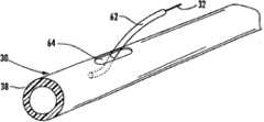
图3是根据本发明的一般分配光缆30(下文中称为分配缆线30)的透视图。分配缆线30描述从诸如缆线外壳的保护层38上的第一获取位置38a突出的分配光纤32。如上所述,第一获取位置38a具有获取长度AL,该长度AL为保护层38上的开口或裂口的长度。此外,分配光纤32具有分配光纤长度DOFL,该分配光纤长度DOFL是获取长度AL的大约5/4倍或更长,且更为优选地,是获取长度AL的大约3/2倍或更长。换句话说,在分配光缆30内的切断位置CL将分配光纤32切断或割断。举例来说,如果获取长度AL(即第一获取位置38a处的保护层38的开口或裂口)为5厘米,则分配光纤32具有大约为6厘米或更长的分配光纤长度DOFL,更优选地,分配光纤长度DOFL为大约7.5厘米或更长。简单地说,分配光纤长度DOFL大于第一获取位置38a的获取长度AL,因为分配光纤是从光缆内切断的。因此,本发明利用保护层上相对小的开口或裂口为该工艺提供合适长度的分配光纤,从而允许用于所选择的分配构造的相对小的印记。当然,缆线30可以具有从第一获取位置38a突出的任何合适数量的分配光纤32。同样地,如果需要,光纤分配缆线能够具有沿着缆线设置的任何数量的获取位置。本发明的光纤分配缆线也可以根据所选择的光缆类型和所需的连接类型利用一种或多种不同的方法和/或部件来构成光纤分配缆线。Figure 3 is a perspective view of a general distribution cable 30 (hereinafter referred to as distribution cable 30) according to the present invention. The
分配缆线30是总称,因为其表示的是根据本发明的允许切断保护层内的分配光纤的光缆。举例来说,图3a-3g描述了根据本发明的有用的光缆结构的样品。图3a-3g分别描述的是:绞合松套管光缆(图3a);有槽铁心光缆(图3b);单管光缆(图3c);扁平带状光缆(图3d);室内光缆(图3e);具有捆绑在一起的多个管的光缆(图3f);具有束的光缆(图3g)。简单地说,分配缆线30能够具有任何合适的结构。此外,本发明也适用于诸如多个光纤带、松散光纤、缓冲光纤、光纤束等的不同缆线类型的光纤。The
图4描述的是利用本发明的原理制造分配缆线的方法的流程图40。首先,步骤41,需要提供诸如具有多根光纤(不可见)和诸如缆线外壳的保护层的分配缆线30的分配缆线。接着,步骤43,执行在分配缆线的第一获取位置上开口(保护层上的开口或裂口)的制造以获取在该分配缆线内的一根或多根光纤。更特别地,保护层被在第一获取位置开口成具有足够实施这里所公开的方法的获取长度AL。本发明的这种方法优于以前的分配方法的一个原因是在每个获取位置只需要一个相对小的开口。此外,根据所选择的分配缆线的结构,其它缆线部件或其部分需要被切断、开口和/或除去以获取在分配缆线内所需要的光纤。例如,技术工人可能必须除去或切掉可水膨胀带,铠装,强度元件等等以开槽获取(gaining access)分配缆线内的多个光纤。此后,方法40需要步骤45选择分配缆线的多根光纤中的至少一根作为分配光纤。Figure 4 depicts a flowchart 40 of a method of manufacturing distribution cables using the principles of the present invention. First, step 41 , a distribution cable such as
然后,工艺执行在下游位置在分配缆线内的切断位置切断该分配光纤32的步骤47(即,割断)。如此所使用的,分配缆线内的切断位置指的是沿着其中保护层未被裂开的分配缆线上的位置。最好地如图6a和6b所示,通过在分配缆线内定位或插入合适的切断工具,从而允许工具在分配缆线内的切断位置切断一根或多根分配光纤来执行该切断步骤。此后,执行引导该分配光纤通过第一获取位置上的开口以便该分配光纤的一部分被设置在保护层的外部的步骤49。在分配光纤被提供到保护层的外部之后,其它可选的步骤也是可能的。例如,分配缆线能够可选地包括诸如提供分界点、过渡管或适于光连接的部件的其它步骤和/或部件。The process then performs a step 47 of severing (ie, cleaving) the distribution
由于其简单、可靠性和工艺顺利,流程40的方法可用于工厂应用和现场应用。举例来说,流程40的方法在每个分配位置只需要一个获取位置开口并且获取位置处提供的分配光纤长度DOFL大于光缆裂口或开口的长度。其它方法可以包括诸如提供其它部件和/或其它步骤的一个或多个可选步骤。更特别地,该方法还可以包括一个或多个步骤,例如:提供过渡管以引导该分配光纤(图6c);提供帽以闭合该第一获取位置(图6c);提供关于分配光纤的分界点(图6i);提供关于分配光纤的限度管(图10);提供用于指引管和/或限度管的插头(图10a);密封第一获取位置(图14);提供指引管以在一个或多个分配光纤中创造过量的光纤长度或带长度(图15);和/或附着套圈、连接器本体等(图17和18)。此外,这里所公开的一组部件可用于实施本发明的方法和/或构造本发明的分配缆线。Due to its simplicity, reliability, and smooth process, the method of Process 40 can be used in factory applications as well as in field applications. For example, the method of process 40 requires only one access location opening per distribution location and the distribution fiber length DOFL provided at the access location is greater than the length of the cable break or opening. Other methods may include one or more optional steps such as providing other components and/or other steps. More particularly, the method may further comprise one or more steps, such as: providing a transition tube to guide the distribution fiber (FIG. 6c); providing a cap to close the first access position (FIG. 6c); providing a demarcation for the distribution fiber point (FIG. 6i); provide confining tubes for dispensing fibers (FIG. 10); provide plugs for indexing tubes and/or confining tubes (FIG. 10a); seal first access position (FIG. 14); Creation of excess fiber length or ribbon length in one or more distribution fibers (FIG. 15); and/or attachment ferrules, connector bodies, etc. (FIGS. 17 and 18). Additionally, the set of components disclosed herein can be used to practice the methods of the invention and/or construct the distribution cables of the invention.
图5描述的是根据本发明的用于割断分配缆线内的一根或多根分配光纤的说明性工具50。工具50具有拉长的本体52,该本体52具有具有开口56和切断元件58的第一端54。切断元件58柔性地匹配在开口56中并且当被拉时能够通过开口56运动,从而在分配缆线内的切断位置割断或切断一根或多根光纤。更特别地,拉动切断元件58导致光纤被切断元件58捕获以向远离它们最终的弯曲半径弯曲以便被割断或切断。最好如图6a所示,切断元件58关于一根或多根分配光纤是松散的并且切断元件58的两端58a和58b被引导通过开口56而且被向着工具50的朝上弯曲的第二端定位,从而形成操作者使用的把手。此后,将工具50滑进分配缆线到所需的切断位置(即切断元件中的环接近切断位置),然后拉动切断元件58的两端58a,58b直到分配缆线内的一根或多根分配光纤被割断。因此,分配光纤长度DOFL的长度大于保护层中裂口的长度,因为分配光纤是在分配缆线内被切断的。Figure 5 depicts an
切断元件58需要某些特征以切断或割断一根或多根分配光纤。例如,切断元件58必须具有必要的强度以便在被拉动时割断分配光纤而不断裂,且具有柔性以便当被拉动移动通过至少一个开口时环形进入拉伸本体的至少一个开口。切断元件58能够使用任何合适的结构、尺寸、形状和/或材料以满足这些要求。例子包括诸如一个或多个细丝、细线、粗纱或纱线的结构,并且形状的例子包括圆形、矩形等。在一实施例中,切断元件58是诸如具有大约2450丹尼尔的凯夫拉尔(Kevlar)的芳族聚酰胺材料。但是,切断元件58可以由其它合适的材料形成,例如,诸如聚酯或尼龙的聚合材料,钓鱼线,诸如钢丝的金属材料,棉花材料等等。例如,一实施例利用例如商标为
同样地,拉长本体52可以由诸如金属或塑料的任何合适材料形成,该材料允许合适的尺寸以匹配在所选择的分配缆线内并且在具有必要强度的同时同样保持一定的柔性。如图5a所示,拉长本体52由具有大约2毫米或更少的工具高度TH以及大约8毫米或更少的工具宽度TW的金属带形成,从而获得一个方向上的柔性。如图所示,开口56是大约5毫米长和大约2毫米宽的普通的矩形形状,但是开口56可以具有其它合适的尺寸和/或形状。当然,可以根据分配缆线的空间尺寸和形状来剪裁拉长的本体的尺寸和形状,因此工具必须匹配在这种矩形或圆形内。例如,具有弓形或棒形的工具可能更好地适于滑进圆形缓冲管。此外,工具50的其它变型也被本发明预期。Likewise, the
图5b-5f描述的是根据本发明的说明性工具的变型。图5b描述了在靠近第一端具有多个开口56b的工具50b的一部分。如图所示,工具50b具有三个开口56b,所以切断元件58的位置可以横跨工具50b的宽度变化。图5c描述了具有开口56c的工具50c的一部分,该开口56c是非圆的并且较大以便当其被拉时容易地使切断元件的端部从其穿过并且引导切断元件。同样地,工具的开口没有必要是自身闭合的。图5d和5e分别描述了工具50d和50e的一部分,其中开口56d和56e都与工具的外边缘相连通,从而使得切断元件58被更容易地插入工具。图5f描述的工具50f具有具有用于拉动切断元件58的可移动部分59f以便割断一根或多根分配光纤的把手57f。如图所示,切断元件58的两个端部58a和58b缠绕在把手57f的可移动部分59f的突出(未标记)上以便在箭头所示的方向拉动可移动部分59时,致动切断元件58的两个端部58a和58b,从而拉动切断元件58的两端58a和58b以切断分配光纤。当然,其它工具变形也能够用于拉动、缠绕、引导和安装,或者以其它方式改变所公开的工具以割断分配光纤。Figures 5b-5f depict a variation of an illustrative tool according to the invention. Figure 5b depicts a portion of a tool 50b having a plurality of openings 56b near the first end. As shown, the tool 50b has three openings 56b, so the position of the cutting
图6a和6b描述的是利用工具50处理图3的分配缆线30。更特别地,图6a示出的是在开口被制造在第一获取位置并且一根或多根光纤被选作分配光纤之后的分配缆线30。如图进一步所示,工具50的切断元件58在被选择的多根分配光纤32上打成环。换句话说,工具50及其切断元件58被定位以切断被该切断元件58的环捕获的多根光纤。此外,切断元件58的两端部58a和58b向工具50的第二端55移动并且切断元件58关于分配光纤32隐蔽(snugged-up)。此后,工具50插入分配缆线30之内并且向下游位置滑动(例如,远离分配缆线的头部)。图6b说明工具50插入分配缆线30内以在切断位置CL割断多根分配光纤。此后,切断元件58的端部58a和58b被足够大的力拉动以割断设置在切断元件58的环和拉长的本体52之间的分配光纤32。在工具50从分配缆线30内移出之后,在分配缆线30内被割断的分配光纤32被引导穿过第一获取位置38a处的开口以便分配光纤的一部分被引导到保护层38a的外部,如图3所示。根据这一点,本发明的分配缆线还可以包括其它制造步骤和/或其它部件以制造本发明的其它组件,例如拼接该分配光纤和/或附着套圈到该分配光纤。Figures 6a and 6b illustrate the use of a
例如,图6c示出了图3的分配缆线30和用于闭合第一获取位置38a和引导分配光纤32到保护层38的外部的一套零件60。更特别地,一套零件60包括引导和保护保护层38外部的分配光纤32的过渡管62以及闭合第一获取位置38a并屏蔽分配缆线内的其它光纤的帽64。在本实施例中,当过渡管被弯曲时,其允许分配光纤进入和离开分配缆线的有限运动(即,允许活塞运动)。一般来说,利用过渡管作为穿过导管时,过渡管允许分配光纤具有允许其有限运动的穿过结构。在另一实施例中,关于在获取位置上或其附近的分配光纤设置分界点,从而一般地阻止其活塞进入或离开分配缆线。穿过结构或分界点结构的使用可以取决于诸如缆线内的光纤耦合度的分配缆线结构和/或缆线特征。换句话说,一些缆线设计更适于自由穿过,而其它缆线构造更适于分界点。此外,如果分配光纤一般材料固定,则可以以分界点的方式使用过渡管,从而创造分界点。For example, FIG. 6c shows the
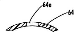
如上所述,帽64包括诸如圆形、矩形等的开口64a,其尺寸适于接收穿过其的过渡管62。在分配光纤32被引导穿过第一获取位置38a并向保护层38外伸出之后,过渡管62在分配光纤32之上滑动并被推进分配缆线30的一部分,如图6e所示。换句话说,过渡管62保护并引导分配光纤,因为当允许一些运动时,它们从分配缆线内的位置向分配缆线外的位置过渡。然后,过渡管62的暴露端被引导穿过帽64的开口64a以便过渡管62从那儿伸出,如图6c中的虚线所示。过渡管62由柔性的合适的材料形成,但是其也可以由相对刚性的材料形成。例如,过渡管62是PTFE管(即
如图6e所示,帽64大于获取位置AL的开口(即,较长)并且被设置以便其一部分从下面的保护层38伸出。此外,帽64可以是相对薄和柔性的以便通过工艺容易地将其在保护层38之下打摺。例如,设定帽64的大小以便在端部有大约5毫米长的帽64被设置在保护层38的下面且帽64具有大约0.3毫米的厚度。在帽64被定位之后,可以执行利用材料66对帽64的固定步骤,如图6f所示。在本实施例中,材料66是可以从Loctite得到的商标为Hysol83245-232的热溶性粘接剂,但是任何其它合适的材料或方法可以用于固定帽,例如胶水、粘接剂、硅树脂、声音焊接等等,只要所使用的材料与其可能接触的光纤、带、保护层、和/或其它部件兼容。此外,帽64和/或材料66同样可以起到阻止诸如过模制密封材料的任何可选密封材料进入分配缆线的作用。此外,能够施加材料66到帽64之下。As shown in Figure 6e, the
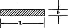
当然,帽64能够具有其它合适的构造并且能够根据分配缆线而改变。例如,帽64能够被成形或剪裁以匹配从分配缆线除去的部分保护层38的形状。换句话说,帽具有匹配第一获取位置的开口的长度和宽度的长度和宽度,以及具有匹配除去部分的保护层的形状的内外形状。因此,帽利用一般平坦的表面闭合第一获取位置。作为例子,一般的圆形分配缆线外壳将利用具有相似的内外径的帽作为具有合适的弧长、轴向长度和宽度的缆线外壳以匹配获取位置开口。图6d示出了帽64的截面图,该帽64被成形成闭合一般圆形的分配缆线的获取位置,但是帽的其它形状、剖面、和/或长度也能够剪裁该帽以配合其它光缆和/或开口。有利地,可以利用诸如粘接剂、胶水、声音焊接等合适的材料或方法将帽64固定到第一获取位置38a。Of course, the
如上所述,流程40的方法需要选择分配缆线的多根光纤中的至少一根光纤作为分配光纤。分配缆线内能够具有任何配置和/或类型的光纤并且本发明的原理可以用于不同配置和/或类型的光纤。例如,本发明适于具有赤裸光纤的缆线(例如,图3a的绞合松套管缆线)和具有一个或多个带的缆线(例如,图3b的有槽铁心缆线,图3c的单管缆线或图3d的扁平带状缆线)。还有其它的分配缆线可具有缓冲光纤(图3e)和光纤束等等。具有缓冲光纤的分配缆线可能需要在切断元件上施加更多的力以割断缓冲层和光纤,但是也在本发明的范围内。在选择用于分配的光纤之后,可以在获取位置利用诸如薄金属或塑料片的分割工具(未示出)分离分配缆线的剩余部分和所选择的光纤。As mentioned above, the method of process 40 needs to select at least one optical fiber among the plurality of optical fibers of the distribution cable as the distribution optical fiber. Any configuration and/or type of optical fiber can be present within the distribution cable and the principles of the present invention can be used with different configurations and/or types of optical fiber. For example, the invention is applicable to cables with bare optical fibers (e.g., the stranded loose-tube cable of FIG. 3a) and cables with one or more ribbons (e.g., the slotted core cable of FIG. 3b, FIG. 3c single tube cable or the flat ribbon cable of Figure 3d). Still other distribution cables may have buffered optical fibers (FIG. 3e), fiber bundles, and the like. Distribution cables with buffered optical fibers may require more force on the severing element to sever the buffer and optical fibers, but are within the scope of the present invention. After selecting the optical fibers for distribution, the remaining portion of the distribution cable and the selected optical fibers may be separated at the access location using a severing tool (not shown), such as a thin metal or plastic sheet.
在利用带的缆线中,可能需要选择少于带中的所有光纤作为分配光纤。例如,在获取位置需要四根分配光纤而分配光缆的每个带具有十二根光纤。如图6g所示,带R具有通过工艺在接近获取位置的较短距离处的带R的第四和第五根光纤之间形成的裂口S。因此,所需要的用于分配的光纤被分离以在将它们切断之前沿着它们轴向长度将带R劈开。更特别地,图6示出了工具50的切断元件58然后在劈开带R的四根分离的光纤周围打成环,并且工具50在此之前被定位。此后,带中的裂口S被在分配光缆内通过工具沿着其轴向长度传播。换句话说,如上所述当工具50在分配光缆内滑到切断位置CL之前,切断元件58沿着其轴向长度通过剪切所需要的光纤之间的带的粘结材料来劈开带,随着工具50滑进位置到切断位置。此后,如上所述利用工具割断一个或多个所选择的分配光纤。In cables utilizing ribbons, it may be necessary to select less than all of the fibers in the ribbon as distribution fibers. For example, four distribution fibers are required at the acquisition location and each ribbon of the distribution cable has twelve fibers. As shown in Figure 6g, the ribbon R has a split S between the fourth and fifth optical fibers of the ribbon R that is formed by the process at a short distance near the take-off location. Accordingly, the optical fibers required for distribution are separated to cleave the ribbons R along their axial length before cutting them. More particularly, FIG. 6 shows that the cutting
如上所述,通常固定分配光纤以阻止运动。图6i描述了具有用于通常地阻止获取位置处或获取位置附近的分配光纤32’的运动的分界点80的分配缆线30’。一般来说,分界点80将分配光纤固定在获取位置附近来阻止分配光纤的运动以便在弯曲时减少分配光纤上不适当的应力,从而保持光学性能。一种用于提供分界点80的方法是通过在获取位置的分配光纤32’周围应用或注入合适的材料。例如,分界材料可以被施加和/或注入分配光纤周围的分配光缆,从而阻止分配光纤的运动。任何合适的材料可被用来作为设置在分配光纤周围的分界点,例如,热溶性粘接剂,硅树脂,等等。但是,用作分界的材料应该与其可能接触的光纤、带、保护层和/或其它部件兼容。此外,分界点80可以和帽64’一起使用,或者不和帽64’一起使用,并且如果使用了帽,该分界点80可以向帽内设置也可以向帽外设置。如果帽被省略,分界点80也可以起到阻止诸如过模制密封材料的任何可选密封材料进入到分配缆线的作用。As mentioned above, the distribution fiber is usually fixed to prevent movement. Figure 6i depicts a distribution cable 30' having a
另外,本发明的原理可以被实施而不切断来自分配缆线内的分配光纤。例如,图6i描述了在保护层38’内具有第一和第二开口38a’和38b’的一般分配缆线30’。换句话说,以传统的获取方法应用分界点80,其中将缆线在两个位置38a’和38b’开口以获得所需要长度的分配光纤。另外,一个或多个开口38a’和38b’可被所描述的合适帽64’闭合。同样地,可执行下述的通过指引为分配光纤提供过量光纤长度的方法而不切断来自分配缆线内的分配光纤。Additionally, the principles of the present invention can be implemented without cutting distribution fibers from within the distribution cable. For example, Figure 6i depicts a generic distribution cable 30' having first and
图7和8分别描述了根据本发明的特殊的说明性光纤分配缆线组件100(下文中称为缆线组件100)的透视图和分解图。最好如图8所示,分配缆线组件100包括分配缆线110,分配光纤抽头115’,用于获取位置AL的帽120,过渡管130,限度管140,指引管150,指引管插头160,接头保护器170,热收缩管180和密封部分190。图9-11分别是组件100沿着线9-9、10-10和11-11的截面图。另外,为了清楚的目的,图10和10a只示出了分配缆线的空腔。缆线组件100包括指引管150以便过量带长度(ERL)或过量光纤长度(EFL)的预定量可被载入分配光纤,下面将描述。装载ERL或EFL到分配光纤中将在缆线组件的弯曲期间抑制分配光纤上的应力。另外,缆线组件100是根据本发明的许多不同分配缆线中的一个例子,其可以包括更少或更多的部件,具有不同构造,不同部件配置等。7 and 8 depict perspective and exploded views, respectively, of a particular illustrative fiber optic distribution cable assembly 100 (hereinafter cable assembly 100 ) in accordance with the present invention. As best shown in FIG. 8, the
图9描述的两种分配光缆110和限度管140具有诸如一般平板形状的一般非圆界面,从而允许组件100的相对小的全部截面尺寸。换句话说,分配缆线110和限度管140的平板部分通常被对准以便和利用两个圆形光缆相比允许小的印记。例如,分配缆线组件100和其它相似的组件能够具有如图11所示的截面最大尺寸MD,其是沿着对角线的。截面最大尺寸MD可以根据所使用的部件的尺寸而变化,但是在实施例中,对于管的特殊应用有利的是截面最大尺寸是大约30毫米或更少,更优选地,是大约28毫米或更少,并且最优选地,是大约25毫米或更少,从而允许缆线组件被拉进入管。当然,对于给定的应用,其它实施例能够具有其它更大或更小的截面最大尺寸。Both
分配缆线110是有利的有几个方面的原因,但是,其它分配缆线的使用是可能的。首先,分配缆线110和其它相似分配缆线是有利的,因为它们具有相对高的光波导数和相对小的截面印记。例如,分配缆线110具有四个带,每个带具有二十四根光纤,总的光纤数为九十六根。由于带具有二十四根光纤数,分配缆线110具有大约15毫米或更小的主缆线尺寸W和大约8毫米或更小的辅缆线尺寸H。其次,容易地从缆线的一般的平板表面的一个(例如,上表面或下表面)获取分配缆线110以便工艺能够获取所需的用于分配的任何光纤。第三,分配缆线110允许快速和可靠地获取,同时在获取工序期间阻止破坏光纤或强度元件。换句话说,技术工人能够简单地切入保护层,从而开槽进入其内具有光纤的光缆腔。同样,在本实施例中,分配缆线110具有干燥的结构(即,光缆不包括阻挡水的油脂或凝胶),因此,技术工人不需要从光纤、带、工具等中清除或移去油脂或凝胶。
当然,根据本发明特定的应用的分配光缆可以具有任何合适的尺寸、结构和/或光纤数。例如,其它分配缆线能够包括其它用于防水的部件和/或结构,例如油脂、凝胶、挤压泡沫、硅树脂或其它合适的防水部件。另外,也可以沿着分配缆线间歇性地设置合适的防水结构。同样地,其它分配缆线能够具有其它合适的缆线部件,例如,铠装、开伞索或管。例如,分配缆线的另一个实施例可以具有可调色部分以定位在埋入式应用中的缆线。Of course, distribution cables may have any suitable size, configuration, and/or fiber count according to a particular application of the present invention. For example, other distribution cables can include other components and/or structures for waterproofing, such as grease, gel, extruded foam, silicone, or other suitable waterproofing components. In addition, suitable waterproofing structures may also be provided intermittently along the distribution cables. Likewise, other distribution cables can have other suitable cable components, such as armor, ripcords, or tubes. For example, another embodiment of a distribution cable may have a tunable portion to position the cable in submerged applications.
如图9所示,分配缆线110包括多根光纤112和保护层118。在本实施例中,分配缆线110是具有用于容纳多根光纤112的腔111的无内胎设计,该多根光纤112构造成以非绞合堆叠式配置的多个带113(以水平线表示)。分配光缆110还包括强度元件114和可水膨胀部件116。如上所述,强度元件114被设置在腔111的相对侧并且给予分配缆线110优先的弯曲特征。强度元件114提供张力和/或抗弯曲强度给分配缆线并且可由诸如电介质、导体、复合物等任何合适的材料形成。举例说明,强度元件114是具有大约2.3毫米直径的圆形玻璃钢(grp),其直径小于腔111的高度。当然,强度元件114能够具有除了圆形之外的形状,例如,椭圆形强度元件。As shown in FIG. 9 , the
利用可水膨胀部件116用作分配光缆110的干燥结构。可水膨胀部件116能够具有任何合适形式,例如,防水纱线、细丝、带等等。在这种情况下,分配缆线110利用两个构造成纺线卷拉长带的可水膨胀部件116。如上所述,可水膨胀部件116的主(例如,平面的)表面(未标记)一般对准腔111的主(例如,水平的)表面(未标记),从而在允许紧凑和有效的构造的同时通常抑制角落光纤接触设置在圆管中的带堆叠的发生。此外,带通常在顶部和底部对准腔111的主表面(即水平表面)并且也通常对准可水膨胀部件116的宽度(即主表面),从而形成腔111内的带/可水膨胀部件复合堆叠。因此,矩形(或正方形)带堆叠被固定到相应的通常为矩形(或正方形)的腔并且避免与在圆形缓冲管内放置矩形(或正方形)带堆叠相关的问题(即,圆形缓冲管中的带堆叠的角落光纤上的应力能够导致缆线不具有诸如弯曲的光学性能要求)。A water-
更特别地,可水膨胀部件116被设置在带堆叠(未标记)的顶部和底部并且包括可压缩层116a和可水膨胀层116b。换句话说,可水膨胀层116夹在非绞合堆叠的多个带113之间,从而形成缆线芯。因此,一个或多个带113,可水膨胀部件116的主表面和腔111的主(水平的)表面通常被对准(即通常是平行的)以产生紧凑结构。另外,可水膨胀部件116接触相应的顶部或底部带的至少一部分。在其它实施例中,一个或多个拉长带可包围在光纤的周围或被设置在光纤的一个或多个侧面。例如,可压缩层116a是诸如开空的聚氨酯泡沫层而可水膨胀层116b是可水膨胀带。但是,其它合适的材料也能够用于可压缩层和/或可水膨胀层或其部分。如图所示,可压缩层116a和可水膨胀层116b附着在一起,但是,它们也可以作为单独部件使用。一般来说,可水膨胀部件116是多功能的,因为其提供带113的耦合度,抑制水沿着腔111的移动,为带/光纤加衬垫,并且能够使带(或光纤)适应分配缆线110的弯曲而运动和分开。在另一实施例中,分配缆线可以使用设置在腔111内的用于耦合光纤,为光纤加衬垫和/或防水的其它缆线部件。例如,分配缆线可以使用不包括防水特征的泡沫带或挤压泡沫。More particularly, water-
如上所示,腔111具有具有固定方向以适应非绞合带堆叠的一般的矩形形状,但是,其它形状或配置的腔也是可能的,例如,一般正方形、圆形或椭圆形。例如,腔可以是以任何合适的方式沿着其轴向长度旋转或绞合的。腔也能够是通过特定角度部分振动的,例如,腔能够在小于全旋转的顺时针角度之间旋转,且然后以小于全旋转的逆时针角度旋转。此外,腔111可以向分配缆线110的一个平面表面偏置,从而允许方便地从一侧开口和获取。As shown above,
用在分配缆线110中的带113能够具有任何合适的设计或带数。例如,通过利用本领域公知的一个或多个子单元或应力集中,带113能够具有可劈开的结构,从而允许将带分割成较小的光纤组。例如,带可以利用子单元,每一个子单元具有四根光纤;但是,没有子单元的带也是可能的并且子单元可以具有不同的光纤数。在沿着其长度利用工具50将其劈开之前,子单元允许光纤带变成可预测的较小光纤数单元的预定劈开。在一实施例中,所描述的每个带113包括六个四光纤子单元,并且总共为二十四根光纤。当然,每个带的其它光纤数目,带数目,和/或其它合适子单元构造也是可能的,例如,取决于网络构造需要的两个十二光纤单元,三个八光纤单元,或六个四光纤单元。合适的光纤配置的例子包括具有或不具有子单元的带,具有紧密缓冲层的加强带,紧密缓冲或有色光纤,管中的松散光纤,模块中的光纤,或成束设置的光纤。The
另外,分配缆线110的本说明性实施例的带113具有大约0.5%或更大,例如在大约0.6%到大约0.8%范围内的过量带长度(ERL)以适应分配光缆110的弯曲和/或卷绕,但是所使用的ERL量可以根据特殊的缆线设计而变化。带113的ERL与缆线内的带的ERL相关并且不同于利用上面简要描述的指引管装载在分配光纤中的ERL。分配缆线110的最小弯曲半径是大约125毫米,其允许光缆以用于松弛存储的相对小的直径卷绕。当然,具有其它合适光纤/带数目的分配缆线可以具有其它ERL值和/或光缆尺寸。举例来说,类似于分配缆线110的缆线能够具有四个具有不同光纤数的带,例如:(1)具有大约12毫米或更小的主缆线尺寸W的十二根光纤带,总数为四十八根光纤;(2)具有大约18毫米或更小的主缆线尺寸W的三十六根光纤带,总数为一百四十四根光纤;(3)具有大约21毫米或更小的主缆线尺寸W的四十八根光纤带,总数为二百一十六根光纤。Additionally, the
另外,腔111具有适于光纤、带等所需的配置的腔高度CH和腔宽度CW。例如,每个带113具有大约0.3毫米的高度和大约1.2毫米(4倍的0.3毫米)的总带高度,并且腔111的腔高度CH是大约5.5毫米。腔宽度CW通常是由为缆线设计的带的宽度(或光纤数)确定并且对于二十四光纤带将是大约7.5毫米。在本实施例中,每个可水膨胀部件116具有大约1.8毫米的未压缩高度,但是,其它合适的未压缩高度也是可能的。如果光缆包括正ERL(即,带在腔内是卷曲的),缆线中的可水膨胀部件116的压缩是其局部最大压缩并且发生在带或带堆叠具有偏离中性轴的最大位移的地方。In addition, the
举例来说,说明性实施例对于未压缩的可水膨胀部件116和带113具有大约4.8毫米的总高度,其小于5.5毫米的腔高度CH。因此,正常的带拉出力通常由由于ERL和/或摩擦力导致可水膨胀部件116的局部最大压缩的卷曲带堆叠导致。例如,当干燥插入的综合未压缩高度是腔高度CH的大约40%或更多时,例如通过在具有大约5毫米的腔高度CH的腔内利用两个1毫米可水膨胀部件116,可以实现带堆叠(或带或光纤)的适当耦合。当然,其它合适比例也是可能的,只要可以保护光学性能。在说明性的实施例中,可水膨胀部件116的综合压缩高度(2倍的1.8毫米等于3.6毫米)是腔高度CH(5.5毫米)的大约65%,其大于腔高度CH的50%。当然,只要依然能够提供合适的性能,腔、带和/或可水膨胀部件116可以具有其它合适的尺寸。例如,可以使用较薄的带和/或水膨胀部件。虽然所描述的腔111是矩形的,可能难于制造所示的矩形腔,即,挤压过程可能产生具有某些不规则矩形形状的腔。同样地,腔除了通常的矩形之外能够具有其它合适的形状,例如,椭圆形,圆形等等,其可能通常改变干燥插入、带和/或腔之间的相对关系(对准)。For example, the illustrative embodiment has an overall height for the uncompressed water-
一般来说,将可水膨胀部件116定位在带堆叠(或单个带或松散的光纤)的相对侧有助于在不同的条件期间影响和维持沿着分配缆线110上的通常均匀的ERL分配,从而有助于保护光学性能。此外,带和光缆的耦合对于例如在通常允许小的缆线弯曲半径的弯曲期间影响沿着缆线的相对连贯的ERL分布是有益的。诸如腔的尺寸和/或一个或多个干燥插入的压缩的其它因素也可以影响沿着缆线的ERL/EFL分配。In general, positioning the water-
具有非绞合带堆叠的一般平板形状的分配缆线的另一个光学性能方面是合适缆线性能所需的ERL的总量。用于适当的缆线性能的ERL总量通常取决于诸如带数的缆线设计。一般来说,通过额定缆线负载上所需的允许光纤应变水平确定用于具有单带缆线的最小ERL;然而,用于多带缆线的最小ERL通常受到弯曲性能的影响。更特别地,当根据缆线设计选择最小ERL限制时,应该考虑强度元件的几何形状和材料(即,截面面积和杨式模量)以计算缆线设计的额定张力负载处所需的光纤应变水平。另外,弯曲所需的ERL量一般随着堆叠中带的数目的增加而增加,因为带堆叠中的外部带更远离光缆的中性轴。但是,ERL的上端对合适的光学性能有限制(即太多ERL能够使光学性能恶化)。此外,具有诸如0.6%到1.5%范围的相对高ERL级的分配缆线可以适于诸如NESC重装载的自立安装,但是用于特定设计的部分ERL应该具有所需要的缆线性能。另一方面,类似于具有松散光纤的分配缆线110的分配缆线可能具有低值的过量光纤长度(EFL),例如,大约0.2%EFL,因为所有光纤都位于光缆的中性轴的附近。Another optical performance aspect of a distribution cable having a generally planar shape of a non-stranded ribbon stack is the total amount of ERL required for proper cable performance. The total amount of ERL for proper cable performance typically depends on cable design such as ribbon count. In general, the minimum ERL for a cable with a single ribbon is determined by the required level of allowable fiber strain on the rated cable load; however, the minimum ERL for a multi-ribbon cable is usually affected by the bending properties. More specifically, when selecting the minimum ERL limit based on the cable design, the geometry and material of the strength element (ie, cross-sectional area and Young's modulus) should be considered to calculate the required fiber strain level at the rated tensile load of the cable design. Additionally, the amount of ERL required for bending generally increases with the number of ribbons in the stack as the outer ribbons in the ribbon stack are further from the neutral axis of the cable. However, the upper end of the ERL has a limit on suitable optical performance (ie too much ERL can degrade the optical performance). Furthermore, distribution cables with relatively high ERL ratings such as in the range of 0.6% to 1.5% may be suitable for self-supporting installations such as NESC heavy loads, but a portion of the ERL for a particular design should have the required cable performance. On the other hand, a distribution cable like
现在回到缆线组件100,图12-16描述的是用于解释制造缆线组件100的方法的不同结构级(即子组件)中的分配缆线110的一部分的透视图。图12描述的是在获取位置AL被制造在保护层118中以及分配光纤115被在分配缆线110内切断并引导通过获取位置AL处具有帽120的开口并且过渡管130被安装之后的分配缆线110,从而形成缆线组件100的子组件102。根据子组件102,可以构造不同的分配缆线,例如,图7和8所示的缆线组件100以及图17和18所示的缆线组件200。此外,子组件102或其它子组件结构都适于现场使用。简单地说,在现场,技术工人将子组件102的分配光纤提供到分配缆线的外部以便使用。如果以这种方式使用,带或其它包层可被设置在分配光纤和/或获取位置的周围以保护它们直到在现场需要获取。Returning now to the
下面将描述子组件102的形成。首先,通过槽形结构和/或火焰创面电灼术使获取位置AL周围的分配光缆110的保护层118变粗糙。变粗糙的保护层118提高了密封部分190与保护层的粘接并且在开口保护层之前更容易和安全地实现。此后,在保护层118中制造获取位置AL的开口118a。开口118a可以是任何合适的长度,并且在本情况下,其是大约25毫米长。任何合适的缆线进入工具都可以用于对保护层118开口,例如,实用刀等。在对保护层118开口之后,分配缆线110的上部可水膨胀部件116的一部分被暴露在获取位置AL。可水膨胀部件116的该暴露部分被除去,例如,利用剪刀切断,从而允许容易地获取分配缆线110内的光纤。此后,选择所需要的用于分配的光纤以便在分配缆线内部将其切断并且可以使用诸如分割工具的特殊的工具。在该例子中,选择少于顶部带中的全部光纤来分配,所以该顶部带包括光纤之间的裂口S,如图6f所示。特别地,选择在获取位置AL的顶部带的四根光纤以成为分配光纤。当然,也可以选择堆叠中的其它带的光纤来分配。另外,如果被获取的带上部的带已经被使用,则所使用的带可以被除去以获取所需要的用于分配的光纤。技术工人利用合适的工具和/或他们的手指在顶部带上制造裂口S。此后,工具50的切断元件58被定位在裂口S周围,如图6f所示。然后,切断元件58的松弛被拉紧并且工具50滑进分配缆线110的腔111中,从而随着工具50移动到位置沿着其轴向长度劈开光纤间的带。在工具50定位在分配光缆110内的切断位置CL之后,切断元件58被足够大的力拉动以切断分配缆线110内的分配光纤115。The formation of
在这种情况下,插入工具50以便切断获取位置AL下游175毫米处的分配光纤115。因此,分配光纤长度DOFL比获取长度AL长大约7倍。在将工具50从分配光缆110移出之后,分配光纤115被拉出腔111并且出现在保护层118的外部。接下来,安装根据具有获取位置AL的分配光缆110设置大小和形状的帽120(类似于帽64)和过渡管130(类似于过渡管62),类似于图6e所示。更特别地,过渡管130具有大约65毫米的长度和通常矩形的形状以在从光纤带113劈开的光纤上滑动,并且帽120通常是平板的并且具有稍微大于获取位置AL的长度以便一部分可以匹配在分配光缆110的腔111内。过渡管130在分配光纤115上滑动以便大约35毫米被设置在分配光缆110的腔111内。然后,过渡管130的暴露端被引导通过帽120的开口120a并且定位帽120以便其一部分被塞入分配光缆110的腔111。在此之前,帽120闭合获取位置AL并且过渡管130保护分配光纤115,因为将它们从分配光缆110引导出来。此后,诸如热溶粘接剂的材料(未示出)被施加在帽120上面和过渡管130周围以固定获取位置开口处的帽120和过渡管130,类似于图6f所示。In this case, the
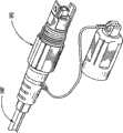
图13描述了用于解释制造方法的缆线组件100的另一个子组件104的透视图。更特别地,图13示出了在拼接具有分配光纤抽头115’的分配光纤115和利用接头保护器170保护拼接位置之后的图12的子组件102。对于本实施例和光缆组件110的获取位置,分配光纤抽头115’是全部熔合地与从顶部带劈出来的分配光纤115拼接的四根光纤带。换句话说,分配光纤抽头115’与分配光纤115光通信并且变成其一部分。此外,这一步骤基于诸如限度管长度的所需要连接构造或其它构造增加了分配光纤的长度。接头保护器170被用来保护和固定接头(不可见)并且在拼接之前可被推到分配光纤抽头115’上并且然后在其被制造之后被定位在接头之上。同样地,根据本实施例的构造,其它部件也可以在分配光纤抽头115’上滑动。类似于子组件102,根据子组件104或其它类似的子组件可以构造不同的分配缆线。缆线组件100包括具有用于光连接的分配光纤的轴端(分配光纤抽头115’的第二端)的限度管140,但是,也可以使用其它构造。例如,分配光纤抽头115’的第二端能够具有附着在其上的一个或多个套圈并且套圈可以是用于即插即用连接的插座,插头等的一部分。作为例子,图19描述了具有附着到套圈上的分配光纤的限度管140’的第二端,该套圈是本领域熟知的插头195的一部分。当然,限度管140’的第二端能够具有用于连接的任何合适的构造,例如,接头就绪光纤、具有套圈的连接器或收容器,多端口等等,从而为技术工人的下游连接提供灵活性。举例来说,图19a描述的是附着到套圈196的分配光纤115’。套圈196是多光纤套圈,但是,单根光纤套圈也可以被附着到一根或多根分配光纤。图19b描述的是具有附着到限度管140的端部的多个插座198a的多端口198。同样地,图19c描述的是具有附着到限度管140的端部的多个插座199a的另一个多端口199。图19d和19e描述的是利用用于即插即用连接分叉腿的限度管分支。更特别地,图19d示出的是具有设置在多个分叉腿193b的端部上的多个插头193a的组件193,而图19e示出的是具有设置在多个分叉腿194b的端部上的多个插座194a的组件194。当然,其它类型和/或结构也能够用于光连接,例如,单个插座等。如下所解释的,光缆组件100具有设置在指引管150的腔内的接头,其将被在下面解释用于保护接头并且装载ERL或EFL到分配光纤中。FIG. 13 depicts a perspective view of another subassembly 104 of the
最好如图10a所示,拼接指引管150在一部分分配光纤115和一部分过渡管130之上滑动。因此,接头保护器170被设置在指引管150的腔150a内并且光纤抽头115’从指引管150的第二端伸出。此外,接头170能够具有诸如设置在其周围的泡沫板的可选的缓冲元件(未示出)。例如,泡沫可被设置在接头170周围,例如,在指引管150在接头170上滑动之前,泡沫在接头170上折叠。如图进一步所示,指引管插头160然后被推入指引管150的下游端部。指引管160被用来在随后的加工过程中阻止密封部分190被注入指引管150。指引管插头160可以由任何合适的材料形成,例如,泡沫、软质高分子等,并且设置其大小以沿着过渡管130通过轻摩擦配合将其匹配在指引管150的腔内。然后,如果需要,指引管150可用带子捆或固定到分配缆线110以将其折叠到合适的位置。在本实施例中,指引管150是分配缆线110的具有空腔的一部分,最好如图11所示。换句话说,指引管150是带113和水膨胀部件116从腔111移出的分配缆线110的一部分(即,只有具有强度元件114的保护层118被嵌入在其内)。当然,具有其它尺寸和/或诸如圆形、正方形等形状的其它合适的指引管的使用也是可能的。As best shown in FIG. 10 a ,
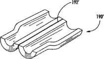
图14描述的是注入可矫正材料以形成密封部分190之前,设置在假想线所示的模块192内的缆线组件100的子组件106的透视图。子组件106还包括施加诸如热溶粘接剂的材料106a以将组件的部件密封和/或固定到一起的步骤,例如,固定过渡管130的位置。施加材料106a阻止注入材料进入指引管,获取位置的开口,和/或在过模制过程期间阻止移动部件,从而保护光学性能。另外,其有助于在其周围形成密封部分190之前更快地加热一部分子组件106以促进密封部分190和子组件106的接合。此后,子组件106被放入如图14所示的铸模192并且通过在压力下注入密封材料到铸模内形成密封部分190。密封部分190提供对于获取位置AL的外部保护并且能够提供结构整体性。在本实施例中,密封部分190是从Loctite获得的异氰酸酯树脂和多羟基硬化剂形成的2部分材料。在本实施例中,密封部分190具有大约3-5毫米的通常均匀的最小壁厚,但是,其它尺寸也是可能的。用于制造密封部分190的其它方法和/或材料也是可能的,只要它们符合所需应用的要求。密封部分190可通过除注入可矫正材料到铸模内之外的技术或制造方法形成。例如,图20描述了一种密封部分190’,其是预先形成的外壳,该外壳匹配子组件106并且然后被加热(或其它反应)以部分或全部熔融和/或形成外壳,从而密封获取位置。更特别地,密封部分190’具有铰合线192’以允许它们关于子组件106折叠。在其它的实施例中,密封部分190’能够是两个或多个分开的部分。诸如密封部分190’的密封部分可以和任何合适的分配缆线一起使用。例如,图20a-20c描述的是可替换密封部分190”和分配缆线110’以及具有圆形截面的限度管140’的使用,从而形成缆线组件100’。在再一个实施例中,加固管(未示出)可被放置在获取位置的周围且然后被注入合适的材料以密封加强管的端部或整个加强管。如果应用允许,也可以利用设置在获取位置周围的热缩管形成密封部分190。FIG. 14 depicts a perspective view of
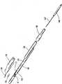
图15描述的是关于指引管150指引限度管140之前的缆线组件100的子组件108的透视图。更特别地,指引限度管140进入指引管150并与其相关能够装载预定量的ERL进入分配光纤115和/或分配光纤抽头115’。因此,分配光纤的ERL和EFL阻止导致可靠性和/或光损耗发生的力被施加到分配光纤。最好如图10所示,设置指引管150的腔150a的大小以便限度管140匹配在指引管150中。图9描述的限度管140包括设置在腔141的相对侧上的多个强度元件142并将一部分分配光纤115’容纳在其内。限度管140具有一般的平板形状,但是,其它尺寸和/或形状的限度管也可以用于本发明的原理。图15描述的是设置在一部分指引管150内并且被拉紧以移出以标记M1表示的过量带长度的限度管140。此后,限度管140被推进(即指引)指引管150由标记M2表示的预定距离D。在本缆线组件中,距离D是大约5毫米,因此大约5毫米的ERL被引入分配光纤,一般来说即是累积在指引管150内。当然,其它合适的距离D也可以用来装载所需要的ERL或EFL。在指引发生之后,限度管140需要被固定在维持ERL或EFL的位置。如图7所示,热缩管180被施加到一部分限度管140和一部分指引管150之上以维持相对位置,但是其它方法也能够用来维持相对位置,例如,过模制等等。另外,需要理解的是可以使用利用第二管指引第一管以提供ERL或EFL的方法而不切断分配缆线内的分配光纤的步骤。当然,缆线组件100的其它变化也是可能的。例如,图16描述的是具有可选的缆线拉杆196以固定分配缆线110和下游端部附近的密封部分190的缆线组件100,从而阻止两者之间的分离力。FIG. 15 depicts a perspective view of the
如上所述,本发明的子组件可以被构造成其它缆线组件结构。例如,图17和18描述的缆线组件200包括具有拼接在其上并由接头保护器270保护的的分配光纤抽头115’的子组件102。最好如图18所示,分配光纤抽头115’保护附着在其上的套圈(不可见)。在本实施例中,套圈是多光纤套圈。此外,套圈是连接器本体220的一部分,从而代替限度管的端部在获取位置提供即插即用光连接。As noted above, the subassemblies of the present invention may be configured into other cable assembly configurations. For example, FIGS. 17 and 18 depict a
当然,缆线组件100和200是根据所公开的原理制造的多管分配缆线的例子。如上所述,其它组件能够利用其它缆线截面或具有更少,更多,和/或不同部件。例如,分配缆线100的密封部分190可以包括如图7中的假想线所示的分段端部190a。分段端部190a允许分配位置的前端的某些应变消除。另外,本发明的缆线组件能够包括其它部件以帮助缆线组件安装到导管中。例如,图21描述的分配缆线300具有设置在获取位置前部的拉动安全装置302,如图所示。更特别地,拉动安全装置302允许技术工人探测导管中的堵塞和/或压缩以便技术工人在试图拉动分配光缆通过导管中的堵塞或压缩时不损坏获取位置。在本实施例中,安全拉动装置的大小被设置得稍微大于密封部分190,从而在到达获取位置之前允许技术工人感觉增加的力和/或损坏拉动安全装置302。当然,安全拉动装置能够具有与密封部分相似或相同的大小和/或形状。因此,技术工人能够在损坏分配缆线之前将分配缆线拉出导管并且在试图重新安装分配缆线之前修复和清理导管。在另一实施例中,安全拉动装置可以被成形以促进分配光缆的扭曲或对准来配合通过堵塞或压缩。Of course,
本领域技术人员将意识到在不脱离本发明的精神和范围下可以做出各种改进和改变。例如,这里所描述的原理可以适应于任何合适的光纤缆线设计。同样地,光纤缆线可包括其它合适的诸如开伞索等的缆线部件或用于光学连接性的其它部件。因此,本发明旨在覆盖落在所附权利要求及其等价物的范围内的本发明的改进和改变。Those skilled in the art will appreciate that various modifications and changes can be made without departing from the spirit and scope of the invention. For example, the principles described herein can be adapted to any suitable fiber optic cable design. Likewise, the fiber optic cable may include other suitable cable components such as ripcord or other components for optical connectivity. Thus, it is intended that the present invention covers the modifications and variations of this invention that come within the scope of the appended claims and their equivalents.
Claims (33)
Applications Claiming Priority (8)
| Application Number | Priority Date | Filing Date | Title |
|---|---|---|---|
| US43265406A | 2006-05-11 | 2006-05-11 | |
| US11/432,311US7346243B2 (en) | 2006-05-11 | 2006-05-11 | Methods for manufacturing fiber optic distribution cables |
| US11/432,654 | 2006-05-11 | ||
| US11/432,579 | 2006-05-11 | ||
| US11/432,579US8582938B2 (en) | 2006-05-11 | 2006-05-11 | Fiber optic distribution cables and structures therefore |
| US11/432,311 | 2006-05-11 | ||
| US11/432,637US7693374B2 (en) | 2006-05-11 | 2006-05-11 | Tools and methods for manufacturing fiber optic distribution cables |
| US11/432,637 | 2006-05-11 |
Related Parent Applications (1)
| Application Number | Title | Priority Date | Filing Date |
|---|---|---|---|
| CN2007800171111ADivisionCN101443684B (en) | 2006-05-11 | 2007-05-11 | Optical distribution cable and its structure |
Publications (2)
| Publication Number | Publication Date |
|---|---|
| CN101872044A CN101872044A (en) | 2010-10-27 |
| CN101872044Btrue CN101872044B (en) | 2013-04-10 |
Family
ID=38923726
Family Applications (1)
| Application Number | Title | Priority Date | Filing Date |
|---|---|---|---|
| CN2010101532318AExpired - Fee RelatedCN101872044B (en) | 2006-05-11 | 2007-05-11 | Fiber optic distribution cables and structures therefor |
Country Status (6)
| Country | Link |
|---|---|
| EP (2) | EP2016453B1 (en) |
| CN (1) | CN101872044B (en) |
| AU (1) | AU2007273241B2 (en) |
| ES (1) | ES2761811T3 (en) |
| PL (2) | PL2016453T3 (en) |
| WO (1) | WO2008008115A2 (en) |
Families Citing this family (5)
| Publication number | Priority date | Publication date | Assignee | Title |
|---|---|---|---|---|
| ES2394717T3 (en) | 2008-03-14 | 2013-02-05 | Prysmian S.P.A. | Procedure for connecting user devices to fiber optic units contained in an optical cable |
| ES2391486T3 (en)* | 2008-11-25 | 2012-11-27 | Ccs Technology Inc. | Hybrid connector |
| FR2956219B1 (en) | 2010-02-05 | 2012-08-17 | Draka Comteq France | CUTTING TOOL AND METHOD FOR DERIVING AT LEAST ONE OPTICAL FIBER FROM A TELECOMMUNICATION CABLE |
| CN103874949B (en)* | 2011-10-11 | 2017-08-25 | 康宁光电通信有限责任公司 | Suppress fiber optic cables boundary of the optical fiber relative to the movement of strength member and related assembly and method |
| CN108732700B (en)* | 2018-05-30 | 2019-12-31 | 烽火海洋网络设备有限公司 | Submarine optical cable branch unit |
Citations (4)
| Publication number | Priority date | Publication date | Assignee | Title |
|---|---|---|---|---|
| US5210812A (en)* | 1991-04-05 | 1993-05-11 | Alcatel Na Cable Systems, Inc. | Optical fiber cable having spliced fiber branch and method of making the same |
| JP2001116968A (en)* | 1999-08-11 | 2001-04-27 | Toyokuni Electric Cable Co Ltd | Optical communication trunk cable and branching tool for optical communication trunk cable |
| US20050111800A1 (en)* | 2003-11-26 | 2005-05-26 | Cooke Terry L. | Pre-connectorized fiber optic distribution cable having multifiber connector |
| US20050259928A1 (en)* | 2004-05-24 | 2005-11-24 | Elkins Robert B Ii | Distribution cable assembly having overmolded mid-span access location |
Family Cites Families (9)
| Publication number | Priority date | Publication date | Assignee | Title |
|---|---|---|---|---|
| JPS6254204A (en)* | 1985-08-10 | 1987-03-09 | Fujikura Ltd | Optical cable branch connection method |
| JP2830032B2 (en)* | 1989-04-20 | 1998-12-02 | 住友電気工業株式会社 | Optical fiber cable branching method and optical fiber cable |
| US6173090B1 (en)* | 1998-10-29 | 2001-01-09 | The United States Of America As Represented By The Secretary Of The Navy | Apparatus for ingress and egress of fiber optic sensor leads from the surface of composite parts and a method for the manufacture thereof |
| US6181857B1 (en)* | 1999-05-12 | 2001-01-30 | Alcatel | Method for accessing optical fibers contained in a sheath |
| US6466725B2 (en)* | 2000-11-29 | 2002-10-15 | Corning Cable Systems Llc | Apparatus and method for splitting optical fibers |
| JP2004037970A (en)* | 2002-07-05 | 2004-02-05 | Toshiba Corp | Optical fiber cable, optical fiber cable branching method |
| US7155093B2 (en)* | 2004-05-24 | 2006-12-26 | Corning Cable Systems Llc | Distribution cable having overmolded mid-span access location with preferential bending |
| US7266274B2 (en)* | 2004-11-03 | 2007-09-04 | Corning Cable Systems Llc | Pre-connectorized fiber optic distribution cable having overmolded access location |
| US20090259928A1 (en)* | 2008-04-03 | 2009-10-15 | Lillie Terrance L | Systems and methods for employee compensation planning |
- 2007
- 2007-05-11ESES16157145Tpatent/ES2761811T3/enactiveActive
- 2007-05-11WOPCT/US2007/011471patent/WO2008008115A2/enactiveApplication Filing
- 2007-05-11PLPL07835759.7Tpatent/PL2016453T3/enunknown
- 2007-05-11PLPL16157145Tpatent/PL3067726T3/enunknown
- 2007-05-11EPEP07835759.7Apatent/EP2016453B1/enactiveActive
- 2007-05-11EPEP16157145.0Apatent/EP3067726B1/enactiveActive
- 2007-05-11AUAU2007273241Apatent/AU2007273241B2/enactiveActive
- 2007-05-11CNCN2010101532318Apatent/CN101872044B/ennot_activeExpired - Fee Related
Patent Citations (4)
| Publication number | Priority date | Publication date | Assignee | Title |
|---|---|---|---|---|
| US5210812A (en)* | 1991-04-05 | 1993-05-11 | Alcatel Na Cable Systems, Inc. | Optical fiber cable having spliced fiber branch and method of making the same |
| JP2001116968A (en)* | 1999-08-11 | 2001-04-27 | Toyokuni Electric Cable Co Ltd | Optical communication trunk cable and branching tool for optical communication trunk cable |
| US20050111800A1 (en)* | 2003-11-26 | 2005-05-26 | Cooke Terry L. | Pre-connectorized fiber optic distribution cable having multifiber connector |
| US20050259928A1 (en)* | 2004-05-24 | 2005-11-24 | Elkins Robert B Ii | Distribution cable assembly having overmolded mid-span access location |
Also Published As
| Publication number | Publication date |
|---|---|
| WO2008008115A3 (en) | 2008-04-17 |
| WO2008008115A2 (en) | 2008-01-17 |
| PL3067726T3 (en) | 2020-06-01 |
| EP3067726B1 (en) | 2019-10-02 |
| CN101872044A (en) | 2010-10-27 |
| PL2016453T3 (en) | 2016-11-30 |
| ES2761811T3 (en) | 2020-05-21 |
| AU2007273241B2 (en) | 2012-04-19 |
| HK1150076A1 (en) | 2011-10-28 |
| EP3067726A1 (en) | 2016-09-14 |
| AU2007273241A1 (en) | 2008-01-17 |
| EP2016453A2 (en) | 2009-01-21 |
| EP2016453B1 (en) | 2016-04-20 |
Similar Documents
| Publication | Publication Date | Title |
|---|---|---|
| US9494764B2 (en) | Fiber optic distribution cables and structures therefor | |
| JP4547367B2 (en) | Manufacturing method of optical fiber wiring cable | |
| US7346243B2 (en) | Methods for manufacturing fiber optic distribution cables | |
| US7272282B1 (en) | Fiber optic cables and assemblies suitable for distribution | |
| US7729583B2 (en) | Flexible optical closure and other flexible optical assemblies | |
| EP1831746B1 (en) | Distribution cable having overmolded mid-span access location with preferential bending | |
| DK2278372T3 (en) | Fiber-optic cables and methods of making them | |
| US7403685B2 (en) | Overmold zip strip | |
| US7941021B2 (en) | Distribution cable assembly having mid-span access location | |
| CN101128764A (en) | Distributed fiber optic cable having at least one access location and method of making same | |
| CN101872044B (en) | Fiber optic distribution cables and structures therefor | |
| JP2007304552A (en) | Parts kit for manufacturing fiber optic distribution cable | |
| HK1150076B (en) | Fiber optic distribution cables and structures therefor |
Legal Events
| Date | Code | Title | Description |
|---|---|---|---|
| C06 | Publication | ||
| PB01 | Publication | ||
| C10 | Entry into substantive examination | ||
| SE01 | Entry into force of request for substantive examination | ||
| REG | Reference to a national code | Ref country code:HK Ref legal event code:DE Ref document number:1150076 Country of ref document:HK | |
| C14 | Grant of patent or utility model | ||
| GR01 | Patent grant | ||
| REG | Reference to a national code | Ref country code:HK Ref legal event code:GR Ref document number:1150076 Country of ref document:HK | |
| CF01 | Termination of patent right due to non-payment of annual fee | ||
| CF01 | Termination of patent right due to non-payment of annual fee | Granted publication date:20130410 Termination date:20200511 |