CN101865413B - Electronic light-emitting device for simulating real fire and method for simulating real fire - Google Patents
Electronic light-emitting device for simulating real fire and method for simulating real fireDownload PDFInfo
- Publication number
- CN101865413B CN101865413BCN2010102114028ACN201010211402ACN101865413BCN 101865413 BCN101865413 BCN 101865413BCN 2010102114028 ACN2010102114028 ACN 2010102114028ACN 201010211402 ACN201010211402 ACN 201010211402ACN 101865413 BCN101865413 BCN 101865413B
- Authority
- CN
- China
- Prior art keywords
- flame
- sheet
- flame sheet
- light
- casing
- Prior art date
- Legal status (The legal status is an assumption and is not a legal conclusion. Google has not performed a legal analysis and makes no representation as to the accuracy of the status listed.)
- Active
Links
Images


Classifications
- F—MECHANICAL ENGINEERING; LIGHTING; HEATING; WEAPONS; BLASTING
- F21—LIGHTING
- F21S—NON-PORTABLE LIGHTING DEVICES; SYSTEMS THEREOF; VEHICLE LIGHTING DEVICES SPECIALLY ADAPTED FOR VEHICLE EXTERIORS
- F21S10/00—Lighting devices or systems producing a varying lighting effect
- F21S10/04—Lighting devices or systems producing a varying lighting effect simulating flames
- F21S10/046—Lighting devices or systems producing a varying lighting effect simulating flames by movement of parts, e.g. by movement of reflectors or light sources
- F—MECHANICAL ENGINEERING; LIGHTING; HEATING; WEAPONS; BLASTING
- F21—LIGHTING
- F21K—NON-ELECTRIC LIGHT SOURCES USING LUMINESCENCE; LIGHT SOURCES USING ELECTROCHEMILUMINESCENCE; LIGHT SOURCES USING CHARGES OF COMBUSTIBLE MATERIAL; LIGHT SOURCES USING SEMICONDUCTOR DEVICES AS LIGHT-GENERATING ELEMENTS; LIGHT SOURCES NOT OTHERWISE PROVIDED FOR
- F21K9/00—Light sources using semiconductor devices as light-generating elements, e.g. using light-emitting diodes [LED] or lasers
- F—MECHANICAL ENGINEERING; LIGHTING; HEATING; WEAPONS; BLASTING
- F21—LIGHTING
- F21S—NON-PORTABLE LIGHTING DEVICES; SYSTEMS THEREOF; VEHICLE LIGHTING DEVICES SPECIALLY ADAPTED FOR VEHICLE EXTERIORS
- F21S10/00—Lighting devices or systems producing a varying lighting effect
- F21S10/04—Lighting devices or systems producing a varying lighting effect simulating flames
- F21S10/043—Lighting devices or systems producing a varying lighting effect simulating flames by selectively switching fixed light sources
- F—MECHANICAL ENGINEERING; LIGHTING; HEATING; WEAPONS; BLASTING
- F21—LIGHTING
- F21S—NON-PORTABLE LIGHTING DEVICES; SYSTEMS THEREOF; VEHICLE LIGHTING DEVICES SPECIALLY ADAPTED FOR VEHICLE EXTERIORS
- F21S6/00—Lighting devices intended to be free-standing
- F21S6/001—Lighting devices intended to be free-standing candle-shaped
- F—MECHANICAL ENGINEERING; LIGHTING; HEATING; WEAPONS; BLASTING
- F21—LIGHTING
- F21S—NON-PORTABLE LIGHTING DEVICES; SYSTEMS THEREOF; VEHICLE LIGHTING DEVICES SPECIALLY ADAPTED FOR VEHICLE EXTERIORS
- F21S9/00—Lighting devices with a built-in power supply; Systems employing lighting devices with a built-in power supply
- F21S9/02—Lighting devices with a built-in power supply; Systems employing lighting devices with a built-in power supply the power supply being a battery or accumulator
- F—MECHANICAL ENGINEERING; LIGHTING; HEATING; WEAPONS; BLASTING
- F21—LIGHTING
- F21V—FUNCTIONAL FEATURES OR DETAILS OF LIGHTING DEVICES OR SYSTEMS THEREOF; STRUCTURAL COMBINATIONS OF LIGHTING DEVICES WITH OTHER ARTICLES, NOT OTHERWISE PROVIDED FOR
- F21V23/00—Arrangement of electric circuit elements in or on lighting devices
- F21V23/001—Arrangement of electric circuit elements in or on lighting devices the elements being electrical wires or cables
- F—MECHANICAL ENGINEERING; LIGHTING; HEATING; WEAPONS; BLASTING
- F21—LIGHTING
- F21V—FUNCTIONAL FEATURES OR DETAILS OF LIGHTING DEVICES OR SYSTEMS THEREOF; STRUCTURAL COMBINATIONS OF LIGHTING DEVICES WITH OTHER ARTICLES, NOT OTHERWISE PROVIDED FOR
- F21V23/00—Arrangement of electric circuit elements in or on lighting devices
- F21V23/003—Arrangement of electric circuit elements in or on lighting devices the elements being electronics drivers or controllers for operating the light source, e.g. for a LED array
- F21V23/007—Arrangement of electric circuit elements in or on lighting devices the elements being electronics drivers or controllers for operating the light source, e.g. for a LED array enclosed in a casing
- F21V23/009—Arrangement of electric circuit elements in or on lighting devices the elements being electronics drivers or controllers for operating the light source, e.g. for a LED array enclosed in a casing the casing being inside the housing of the lighting device
- F—MECHANICAL ENGINEERING; LIGHTING; HEATING; WEAPONS; BLASTING
- F21—LIGHTING
- F21V—FUNCTIONAL FEATURES OR DETAILS OF LIGHTING DEVICES OR SYSTEMS THEREOF; STRUCTURAL COMBINATIONS OF LIGHTING DEVICES WITH OTHER ARTICLES, NOT OTHERWISE PROVIDED FOR
- F21V23/00—Arrangement of electric circuit elements in or on lighting devices
- F21V23/04—Arrangement of electric circuit elements in or on lighting devices the elements being switches
- F21V23/0407—Arrangement of electric circuit elements in or on lighting devices the elements being switches for flashing
- F—MECHANICAL ENGINEERING; LIGHTING; HEATING; WEAPONS; BLASTING
- F21—LIGHTING
- F21V—FUNCTIONAL FEATURES OR DETAILS OF LIGHTING DEVICES OR SYSTEMS THEREOF; STRUCTURAL COMBINATIONS OF LIGHTING DEVICES WITH OTHER ARTICLES, NOT OTHERWISE PROVIDED FOR
- F21V9/00—Elements for modifying spectral properties, polarisation or intensity of the light emitted, e.g. filters
- F21V9/30—Elements containing photoluminescent material distinct from or spaced from the light source
- H—ELECTRICITY
- H01—ELECTRIC ELEMENTS
- H01F—MAGNETS; INDUCTANCES; TRANSFORMERS; SELECTION OF MATERIALS FOR THEIR MAGNETIC PROPERTIES
- H01F7/00—Magnets
- H01F7/06—Electromagnets; Actuators including electromagnets
- H01F7/064—Circuit arrangements for actuating electromagnets
- H—ELECTRICITY
- H05—ELECTRIC TECHNIQUES NOT OTHERWISE PROVIDED FOR
- H05B—ELECTRIC HEATING; ELECTRIC LIGHT SOURCES NOT OTHERWISE PROVIDED FOR; CIRCUIT ARRANGEMENTS FOR ELECTRIC LIGHT SOURCES, IN GENERAL
- H05B45/00—Circuit arrangements for operating light-emitting diodes [LED]
- H05B45/10—Controlling the intensity of the light
- H—ELECTRICITY
- H05—ELECTRIC TECHNIQUES NOT OTHERWISE PROVIDED FOR
- H05B—ELECTRIC HEATING; ELECTRIC LIGHT SOURCES NOT OTHERWISE PROVIDED FOR; CIRCUIT ARRANGEMENTS FOR ELECTRIC LIGHT SOURCES, IN GENERAL
- H05B45/00—Circuit arrangements for operating light-emitting diodes [LED]
- H05B45/30—Driver circuits
- H05B45/37—Converter circuits
- H05B45/3725—Switched mode power supply [SMPS]
- H05B45/385—Switched mode power supply [SMPS] using flyback topology
- H—ELECTRICITY
- H05—ELECTRIC TECHNIQUES NOT OTHERWISE PROVIDED FOR
- H05B—ELECTRIC HEATING; ELECTRIC LIGHT SOURCES NOT OTHERWISE PROVIDED FOR; CIRCUIT ARRANGEMENTS FOR ELECTRIC LIGHT SOURCES, IN GENERAL
- H05B47/00—Circuit arrangements for operating light sources in general, i.e. where the type of light source is not relevant
- H05B47/10—Controlling the light source
- H05B47/16—Controlling the light source by timing means
- F—MECHANICAL ENGINEERING; LIGHTING; HEATING; WEAPONS; BLASTING
- F21—LIGHTING
- F21W—INDEXING SCHEME ASSOCIATED WITH SUBCLASSES F21K, F21L, F21S and F21V, RELATING TO USES OR APPLICATIONS OF LIGHTING DEVICES OR SYSTEMS
- F21W2121/00—Use or application of lighting devices or systems for decorative purposes, not provided for in codes F21W2102/00 – F21W2107/00
- F—MECHANICAL ENGINEERING; LIGHTING; HEATING; WEAPONS; BLASTING
- F21—LIGHTING
- F21Y—INDEXING SCHEME ASSOCIATED WITH SUBCLASSES F21K, F21L, F21S and F21V, RELATING TO THE FORM OR THE KIND OF THE LIGHT SOURCES OR OF THE COLOUR OF THE LIGHT EMITTED
- F21Y2115/00—Light-generating elements of semiconductor light sources
- F21Y2115/10—Light-emitting diodes [LED]
- Y—GENERAL TAGGING OF NEW TECHNOLOGICAL DEVELOPMENTS; GENERAL TAGGING OF CROSS-SECTIONAL TECHNOLOGIES SPANNING OVER SEVERAL SECTIONS OF THE IPC; TECHNICAL SUBJECTS COVERED BY FORMER USPC CROSS-REFERENCE ART COLLECTIONS [XRACs] AND DIGESTS
- Y02—TECHNOLOGIES OR APPLICATIONS FOR MITIGATION OR ADAPTATION AGAINST CLIMATE CHANGE
- Y02B—CLIMATE CHANGE MITIGATION TECHNOLOGIES RELATED TO BUILDINGS, e.g. HOUSING, HOUSE APPLIANCES OR RELATED END-USER APPLICATIONS
- Y02B20/00—Energy efficient lighting technologies, e.g. halogen lamps or gas discharge lamps
- Y02B20/40—Control techniques providing energy savings, e.g. smart controller or presence detection
- Y—GENERAL TAGGING OF NEW TECHNOLOGICAL DEVELOPMENTS; GENERAL TAGGING OF CROSS-SECTIONAL TECHNOLOGIES SPANNING OVER SEVERAL SECTIONS OF THE IPC; TECHNICAL SUBJECTS COVERED BY FORMER USPC CROSS-REFERENCE ART COLLECTIONS [XRACs] AND DIGESTS
- Y10—TECHNICAL SUBJECTS COVERED BY FORMER USPC
- Y10S—TECHNICAL SUBJECTS COVERED BY FORMER USPC CROSS-REFERENCE ART COLLECTIONS [XRACs] AND DIGESTS
- Y10S362/00—Illumination
- Y10S362/806—Ornamental or decorative
- Y10S362/81—Imitation candle
- Y—GENERAL TAGGING OF NEW TECHNOLOGICAL DEVELOPMENTS; GENERAL TAGGING OF CROSS-SECTIONAL TECHNOLOGIES SPANNING OVER SEVERAL SECTIONS OF THE IPC; TECHNICAL SUBJECTS COVERED BY FORMER USPC CROSS-REFERENCE ART COLLECTIONS [XRACs] AND DIGESTS
- Y10—TECHNICAL SUBJECTS COVERED BY FORMER USPC
- Y10T—TECHNICAL SUBJECTS COVERED BY FORMER US CLASSIFICATION
- Y10T29/00—Metal working
- Y10T29/49—Method of mechanical manufacture
- Y10T29/49002—Electrical device making
- Y10T29/4902—Electromagnet, transformer or inductor
Landscapes
- Engineering & Computer Science (AREA)
- General Engineering & Computer Science (AREA)
- Physics & Mathematics (AREA)
- Electromagnetism (AREA)
- Microelectronics & Electronic Packaging (AREA)
- Power Engineering (AREA)
- Optics & Photonics (AREA)
- Spectroscopy & Molecular Physics (AREA)
- Non-Portable Lighting Devices Or Systems Thereof (AREA)
- Catching Or Destruction (AREA)
Abstract
Description
Translated fromChinese技术领域technical field
本发明涉及一种电子发光装置。The invention relates to an electronic light emitting device.
背景技术Background technique
日常生活中,各种电子发光装置被广泛应用于玩具、家居装饰用品、礼品中。例如,人们原本是把蜡烛、煤油灯等当成一种照明灯具,但随着电光源的普遍使用,其照明功能逐渐淡化,人们对蜡烛、煤油灯等的需求也由实用性转为观赏性或情趣性,于是电子闪光蜡烛、电子蜡烛、仿真蜡烛和仿真煤油灯等各种电子发光装置也应运而生。这类电子发光装置的发光部分试图模拟蜡烛或煤油灯的发光形态,模拟其灯光闪烁、忽明忽暗等情景,但与真实的蜡烛或煤油灯点燃的真火焰相比,区别较大,视觉体验尚不够真实。In daily life, various electronic light-emitting devices are widely used in toys, home decoration products, and gifts. For example, people originally regarded candles, kerosene lamps, etc. as lighting fixtures, but with the widespread use of electric light sources, their lighting functions have gradually faded, and people's demand for candles, kerosene lamps, etc. has also changed from practicality to ornamental or Interesting, so various electronic lighting devices such as electronic flashing candles, electronic candles, simulation candles and simulation kerosene lamps have also emerged at the historic moment. The light-emitting part of this type of electronic light-emitting device tries to simulate the light-emitting form of a candle or kerosene lamp, simulating the flickering, flickering and dimming of the light, but compared with the real flame lit by a real candle or kerosene lamp, there is a big difference. The experience is not real enough.
比如在专利号为200520035772.5、名称为《电子模拟闪光蜡烛》的中国专利中,采用一个形状模拟为真实火焰的火焰壳,内置LED发光元件,控制电路控制LED发光元件的点亮时序,使LED发光元件时亮时灭,视觉效果表现出光线忽明忽暗、闪动跳跃;以增强装置的趣味性和观赏性。For example, in the Chinese patent with the patent number 200520035772.5 and the name "Electronic Simulation Flashing Candle", a flame shell whose shape is simulated as a real flame is used, and a built-in LED light-emitting element is used. The control circuit controls the lighting timing of the LED light-emitting element to make the LED emit light. The components are on and off, and the visual effect shows that the light is flickering, flickering and jumping; to enhance the fun and appreciation of the device.
发明内容Contents of the invention
本发明的主要目的是,提供一种视觉体验更加逼真的发光装置和方法。The main purpose of the present invention is to provide a lighting device and method with more realistic visual experience.
为解决上述技术问题,本发明提出了一种模拟真火的电子发光装置,包括机芯,所述机芯包括机壳、发光元件、火焰片和摆动机构;所述机壳顶部开设有一机壳通孔;所述火焰片活动支设或悬挂于所述机壳上,该火焰片包括模拟为火焰形状的上片,该上片通过通孔被显露于所述机壳外;所述发光元件安装于所述机壳上或机壳内,该发光元件的光线出射方向与所述上片表面相交,使发光元件的光线投射在上片表面;所述摆动机构设于所述火焰片下面,用于在受电后对该火焰片施加作用力,使该火焰片晃动或摆动。In order to solve the above-mentioned technical problems, the present invention proposes an electronic light-emitting device that simulates a real fire, including a movement, and the movement includes a casing, a light-emitting element, a flame sheet and a swing mechanism; a casing is arranged on the top of the casing A through hole; the flame sheet is movably supported or suspended on the casing, and the flame sheet includes an upper piece simulated as a flame shape, and the upper piece is exposed outside the casing through the through hole; the light-emitting element Installed on the casing or in the casing, the light emitting direction of the light-emitting element intersects with the surface of the upper sheet, so that the light of the light-emitting element is projected on the surface of the upper sheet; the swing mechanism is arranged under the flame sheet, It is used to apply force to the flame sheet after receiving electricity, so that the flame sheet shakes or swings.
上述的模拟真火的电子发光装置,其中的实施例中,还包括用于控制所述摆动机构和发光元件的PCB主板,与所述发光元件和摆动机构电连接。The above-mentioned electronic lighting device for simulating a real fire, in an embodiment thereof, further includes a PCB main board for controlling the swing mechanism and the light-emitting element, and is electrically connected with the light-emitting element and the swing mechanism.
上述的模拟真火的电子发光装置,其中的实施例中,所述摆动机构包括磁铁组、联动片和线圈;所述磁铁组包括第一磁铁、第二磁铁和第三磁铁;所述联动片于中部位置具有一支撑点,通过该支撑点活动支设或悬挂于所述机壳内,在自重的作用下所述联动片垂挂于所述机壳内;所述第一磁铁安装于所述火焰片下端部,所述第二磁铁安装于所述联动片的上端部,所述第一磁铁与第二磁铁相对,所述第三磁铁安装于所述联动片的下端部,所述线圈位于所述第三磁铁的下方,所述第三磁铁与所述线圈相对。In the above-mentioned electronic light-emitting device for simulating real fire, in the embodiment, the swing mechanism includes a magnet group, a link piece and a coil; the magnet set includes a first magnet, a second magnet and a third magnet; the link piece There is a supporting point in the middle, through which the supporting point is movably supported or suspended in the casing, and the linkage piece hangs in the casing under the action of its own weight; the first magnet is installed on the The lower end of the flame sheet, the second magnet is installed on the upper end of the linkage piece, the first magnet is opposite to the second magnet, the third magnet is installed on the lower end of the linkage piece, and the coil is located at Below the third magnet, the third magnet is opposite to the coil.
上述的模拟真火的电子发光装置,其中的实施例中,还包括壳体和机座;所述壳体设置有一壳体通孔,所述机芯安装于该壳体内;所述火焰片的上片由所述壳体通孔伸出于所述壳体顶部;所述机座安装于该机芯下部,并与所述机芯相接;所述PCB主板安装于该机座上。The above-mentioned electronic light-emitting device for simulating a real fire, in the embodiment, also includes a casing and a base; the casing is provided with a casing through hole, and the core is installed in the casing; the flame sheet The upper piece protrudes from the through hole of the housing on the top of the housing; the base is installed at the lower part of the movement and connected to the movement; the PCB main board is installed on the base.
上述的模拟真火的电子发光装置,其中的实施例中,所述机芯还包括一火焰片支杆所述火焰片支杆支设或架设于所述机壳的所述通孔近端;所述火焰片中部设有一火焰片通孔,所述火焰片通孔的上部为所述上片,所述火焰片支杆穿过所述火焰片通孔,将所述火焰片活动支设或悬挂于所述火焰片支杆;所述机芯还包括一联动片支杆,支设或架设所述机壳内,所述联动片中部设有一联动片通孔,所述联动片支杆穿过所述联动片通孔,将所述联动片活动支设或悬挂于所述联动片支杆。In the above-mentioned electronic lighting device for simulating a real fire, in the embodiment, the movement further includes a flame sheet support rod, and the flame sheet support rod is supported or erected on the near end of the through hole of the casing; The middle part of the flame sheet is provided with a flame sheet through hole, and the upper part of the flame sheet through hole is the upper sheet, and the flame sheet rod passes through the flame sheet through hole, and the flame sheet is movably supported or hanging on the flame piece rod; the movement also includes a linkage piece pole, which is supported or erected in the casing, and a linkage piece through hole is provided in the middle of the linkage piece, and the linkage piece pole passes through Through the through hole of the linkage piece, the linkage piece is movably supported or suspended on the linkage piece rod.
其中的实施例中,所述PCB主板设置有控制电路,该控制电路包括微控制器和MOS管或三极管,该微控制器通过输出PWM信号至该MOS管或三极管,产生振荡信号给所述线圈,使该线圈间歇性产生磁场。In one of the embodiments, the PCB main board is provided with a control circuit, the control circuit includes a microcontroller and a MOS tube or a triode, and the microcontroller generates an oscillation signal to the coil by outputting a PWM signal to the MOS tube or the triode , causing the coil to generate a magnetic field intermittently.
其中的实施例中,所述发光元件的光线出射方向与该火焰片上片的夹角选择在30-40度间,使投射在该上片的光斑形状模拟真实火焰的形状。In one of the embodiments, the included angle between the light emitting direction of the light-emitting element and the upper sheet of the flame sheet is selected to be between 30-40 degrees, so that the shape of the light spot projected on the upper sheet simulates the shape of a real flame.
其中的实施例中,所述摆动机构包括磁铁和线圈;所述磁铁安装于所述火焰片的下端部,所述线圈与火焰片下端部的磁铁相对;通过线圈产生与火焰片的下端部处的磁铁极性相异的磁场,使二者产生相斥。In one of the embodiments, the swing mechanism includes a magnet and a coil; the magnet is installed on the lower end of the flame sheet, and the coil is opposite to the magnet at the lower end of the flame sheet; The magnetic field of different polarities of the magnets makes the two repel each other.
其中的实施例中,所述摆动机构包括挂绳、摆动块、旋转块和马达;该挂绳上端挂设于火焰片31下端部,该挂绳下端连接该摆动块,该马达被固定于所述机壳内,该旋转块与马达的输出轴固接;自然状态下,该摆动块依靠自身的重量垂挂在该挂绳上,该摆动块的下端部接触该旋转块;当该马达驱动时,该旋转块碰撞该摆动块带动该火焰片晃动或摆动。In one of the embodiments, the swing mechanism includes a hanging rope, a swinging block, a rotating block and a motor; the upper end of the hanging rope is hung on the lower end of the
其中的实施例中,所述摆动机构包括连杆、转动块和马达;该连杆上端连接于所述火焰片,该连杆未端与该转动块的外壁相接触;该转动块设有一挡块,自然状态下该挡块与火焰片的下端部相接触;马达固定于所述机壳内,该转动块与该马达的输出轴固接;当马达驱动时,转动块被带动并碰撞该连杆未端,该挡块碰撞该火焰片下端部,使火焰片晃动或摆动。In one of the embodiments, the swing mechanism includes a connecting rod, a rotating block and a motor; the upper end of the connecting rod is connected to the flame sheet, and the end of the connecting rod is in contact with the outer wall of the rotating block; the rotating block is provided with a stop Block, the block is in contact with the lower end of the flame sheet in a natural state; the motor is fixed in the casing, and the rotating block is fixedly connected to the output shaft of the motor; when the motor is driven, the rotating block is driven and hits the At the end of the connecting rod, the block collides with the lower end of the flame sheet, causing the flame sheet to shake or swing.
其中的实施例中,所述摆动机构包括一风扇,固定于所述机壳底部,出风方向朝向所述机壳通孔;所述火焰片的下端部设为面迎出风方向的挡板;当该风扇启动时,该火焰片的挡板正面迎风,使火焰片在风力作用下不停晃动。In one of the embodiments, the oscillating mechanism includes a fan, which is fixed on the bottom of the casing, and the air outlet direction faces the through hole of the casing; the lower end of the flame sheet is set as a baffle facing the air outlet direction ; When the fan is started, the baffle plate of the flame sheet is facing the wind, so that the flame sheet is constantly shaking under the action of the wind.
其中的实施例中,所述火焰片支杆二端分别架设于所述机壳上,中间下凹,整体呈V型。In one of the embodiments, the two ends of the flame sheet support rod are erected on the casing respectively, the middle is concave, and the whole is V-shaped.
其中的实施例中,所述联动片支杆二端分别架设于所述机壳上,中间下凹,整体呈V型;在自由状态下,所述联动片垂直悬挂于所述联动片支杆上。In one of the embodiments, the two ends of the link rod are respectively erected on the casing, the middle is concave, and the overall shape is V-shaped; in the free state, the link is vertically suspended from the link rod superior.
其中的实施例中,以所述火焰片通孔的下部为下片,所述火焰片的上片自重轻于火焰片的下片,在自由状态下,所述火焰片垂直悬挂于所述火焰片支杆上。Among the embodiments, the lower part of the through hole of the flame sheet is used as the lower sheet, and the weight of the upper sheet of the flame sheet is lighter than that of the lower sheet of the flame sheet. In a free state, the flame sheet hangs vertically on the flame piece on the pole.
其中的实施例中,所述机座包括电池弹片、电池座和电池盖,所述PCB主板安装于该机座上,并与所述电池弹片电连接。In one of the embodiments, the base includes a battery elastic piece, a battery seat and a battery cover, and the PCB main board is installed on the base and is electrically connected with the battery elastic piece.
其中的实施例中,还包括外壳;套设于所述壳体外,该外壳包括围合成管状的侧壁和横隔板,该横隔板与该侧壁的轴向相交,该横隔板的中间开设有一横隔板通孔;所述火焰片的上片由该横隔板通孔伸出显现于所述外壳顶部;该侧壁位于所述横隔板之上的部分高度不规则变化,并形成一个缺口。Among the embodiments, it also includes a casing; sleeved outside the casing, the casing includes a tubular side wall and a diaphragm, the diaphragm intersects with the axial direction of the side wall, and the diaphragm of the diaphragm There is a through hole of the diaphragm in the middle; the upper piece of the flame sheet protrudes from the through hole of the diaphragm and appears on the top of the shell; the height of the part of the side wall above the diaphragm varies irregularly, and form a gap.
同时,本发明提出了一种模拟真火的方法,采用火焰片,悬挂于机壳上,该火焰片包括模拟为火焰形状的上片,该上片被显露于机壳顶部;采用发光元件安装于机壳,该发光元件的光线出射方向与所述上片相交,使发光元件的光线投射在上片表面;采用摆动机构设于所述火焰片下面,该摆动机构通电时对该火焰片施加作用力,使该火焰片晃动或摆动。At the same time, the present invention proposes a method for simulating a real fire, which uses a flame sheet and hangs it on the casing. In the casing, the light emission direction of the light-emitting element intersects with the upper sheet, so that the light of the light-emitting element is projected on the surface of the upper sheet; a swing mechanism is used to set it under the flame sheet, and when the swing mechanism is energized, the flame sheet is applied. A force is applied to shake or swing the flame sheet.
上述的模拟真火的方法,其中的实施例中,于火焰片下端部加设磁铁;所述摆动机构采用磁力机构,利用脉冲信号通过三极管或MOS管产生振荡,使线圈产生磁场,利用磁场的相吸或相斥作用,从而使火焰片晃动或摆动。The above-mentioned method for simulating a real fire, in the embodiment, a magnet is added at the lower end of the flame sheet; the swing mechanism adopts a magnetic mechanism, and a pulse signal is used to generate oscillation through a triode or a MOS tube, so that the coil generates a magnetic field. Attract or repel each other, so that the flame sheet shakes or swings.
上述的模拟真火的方法,其中的实施例中,所述摆动机构采用风扇,设于所述火焰片下面;该火焰片的下端设置成一个迎风的挡板,与风扇的出风方向相对;用风扇产生的风力使该火焰片保持晃动或摆动。In the above method for simulating a real fire, in the embodiment, the swing mechanism adopts a fan, which is arranged under the flame sheet; the lower end of the flame sheet is set as a windward baffle, opposite to the wind outlet direction of the fan; The flame sheet is kept shaking or swinging by the wind force generated by the fan.
上述的模拟真火的方法,其中的实施例中,所述摆动机构采用马达和连接件,该马达驱动该连接件,该连接件间歇碰撞该火焰片,使该火焰片晃动或摆动。In the above-mentioned method for simulating real fire, in the embodiment, the swing mechanism adopts a motor and a connecting piece, the motor drives the connecting piece, and the connecting piece hits the flame piece intermittently, causing the flame piece to vibrate or swing.
上述的模拟真火的方法,其中的实施例中,发光元件的光线出射方向与该火焰片上片的夹角选择在30-40度间,使投射在该上片的光斑形状模拟真实火焰的形状。In the above method for simulating real fire, in the embodiment, the angle between the light emitting direction of the light-emitting element and the upper sheet of the flame sheet is selected between 30-40 degrees, so that the shape of the spot projected on the upper sheet simulates the shape of a real flame .
其中的实施例中,发光元件选择LED灯,该LED灯的光线出射角度选择在7-10度之间,使出射光线集中投射于该火焰片的上片表面。In one of the embodiments, the light-emitting element is an LED lamp, and the light emission angle of the LED light is selected between 7-10 degrees, so that the outgoing light is concentrated and projected on the upper surface of the flame sheet.
其中的实施例中,设置控制电路,该控制电路包括微控制器和MOS管或三极管,该微控制器通过输出PWM信号至该MOS管或三极管,产生振荡信号给所述线圈,使该线圈间歇性产生磁场。In one of the embodiments, a control circuit is set, the control circuit includes a microcontroller and a MOS tube or a triode, and the microcontroller generates an oscillating signal to the coil by outputting a PWM signal to the MOS tube or the triode, so that the coil is intermittently Sex produces a magnetic field.
本发明与现有技术相比较的有益效果是:The beneficial effect that the present invention compares with prior art is:
本发明中,通过火焰片与投射光线的配合,火焰片会在摆动机构和自身重力的作用下晃动,而发光元件发出的光线投影在火焰片上,看上去有如一团真正的火焰摇曳不定、忽明忽暗,使得发光装置模拟的火焰更加接近于真实蜡烛、煤油灯等传统照明装置的灯芯火焰,本发明的装置应用于电子蜡烛、仿真煤油灯等电子产品中,进一步提升产品的视觉体验,使得产品模拟真火的效果更为逼真,更具趣味性与观赏性。In the present invention, through the cooperation of the flame sheet and the projected light, the flame sheet will shake under the action of the swing mechanism and its own gravity, and the light emitted by the light-emitting element is projected on the flame sheet, which looks like a real flame flickering and flickering. Brightness and darkness make the flame simulated by the light-emitting device closer to the wick flame of traditional lighting devices such as real candles and kerosene lamps. The device of the present invention is applied to electronic products such as electronic candles and simulated kerosene lamps to further improve the visual experience of the products. It makes the effect of product simulating real fire more realistic, more interesting and ornamental.
在其中的一些实施例中,本发明的装置中的摆动机构,采用磁力机构,保证使用过程中火焰片保持随机或有序的晃动,从而使投射到火焰片上的光线一直保持摇曳不定,看上去相当逼真。In some of the embodiments, the oscillating mechanism in the device of the present invention adopts a magnetic mechanism to ensure that the flame sheet keeps shaking randomly or orderly during use, so that the light projected on the flame sheet remains swaying all the time. Pretty realistic.
在其中的一些实施例中,本发明的装置,发光元件发出光线的投射角度选择在一定的范围内,可以保证投射光线落在火焰片上,从而保证模拟真火的视觉效果。In some of the embodiments, in the device of the present invention, the projection angle of the light emitted by the light-emitting element is selected within a certain range, which can ensure that the projected light falls on the flame sheet, thereby ensuring the visual effect of simulating real fire.
在其中的一些实施例中,本发明的装置,火焰片的结构是上轻下重,在外力的作用下更为容易晃动,从而保证模拟真火的视觉效果。In some of the embodiments, in the device of the present invention, the structure of the flame sheet is light at the top and heavy at the bottom, which is easier to shake under the action of external force, thereby ensuring the visual effect of simulating real fire.
附图说明Description of drawings
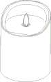
图1为本发明实施例一的电子蜡烛外观示意图;Figure 1 is a schematic diagram of the appearance of an electronic candle according to
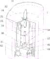
图2为本发明实施例一的电子蜡烛结构剖示图;Fig. 2 is a schematic sectional view of the structure of an electronic candle according to
图3为本发明实施例一的电子蜡烛结构分解示意图;Fig. 3 is a schematic exploded view of the structure of an electronic candle according to
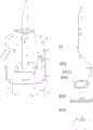
图4为本发明实施例一的电子蜡烛的机芯结构示意图;Fig. 4 is a schematic diagram of the movement structure of the electronic candle according to
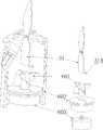
图5是本发明实施例一的电子蜡烛机芯结构分解示意图;Fig. 5 is an exploded schematic diagram of the structure of the electronic candle movement according to
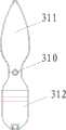
图6是本发明实施例一的电子蜡烛的火焰片的结构示意图;6 is a schematic structural view of the flame sheet of the electronic candle according to
图7是本发明实施例一的电子蜡烛的电路部分原理图;Fig. 7 is a schematic diagram of the circuit part of the electronic candle according to
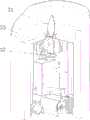
图8是本发明实施例二的电子蜡烛结构剖示图;Fig. 8 is a sectional view of the structure of an electronic candle according to
图9是本发明实施例三的电子蜡烛机芯结构分解示意图;Fig. 9 is an exploded schematic diagram of the structure of the electronic candle movement according to
图10是本发明实施例三的电子蜡烛的电路部分原理图;Fig. 10 is a schematic diagram of the circuit part of the electronic candle according to the third embodiment of the present invention;
图11是本发明实施例四的电子蜡烛机芯结构分解示意图;Fig. 11 is an exploded schematic diagram of the structure of the electronic candle movement according to
图12是本发明实施例五的电子蜡烛机芯结构分解示意图;Fig. 12 is an exploded schematic diagram of the structure of the electronic candle movement according to Embodiment 5 of the present invention;
图13是本发明实施例六的电子蜡烛机芯结构分解示意图;Fig. 13 is an exploded schematic diagram of the structure of the electronic candle movement according to Embodiment 6 of the present invention;
具体实施方式Detailed ways
下面通过具体的实施例并结合附图对本发明作进一步详细描述。The present invention will be described in further detail below through specific embodiments and in conjunction with the accompanying drawings.
实施例一:Embodiment one:
本实施例具体产品为一个电子蜡烛,请结合图1、图2、图3、图4和图5所示,图1为本例电子蜡烛的外观示意图,整体模拟蜡烛的形状,包括:外壳1;壳体2,套装于外壳1内;机芯3和机座4,安装于该壳体2内。壳体2的顶部中间开设有一壳体通孔,一火焰片设于其中,火焰片伸出该壳体通孔的部分形状模拟为蜡烛点燃时的蜡焰,机芯上的发光元件发出的光线以一定的角度投射在该火焰片伸出通孔的部分,且该火焰片可以在自然风或设于机芯内的摆动机构的作用下自由晃动,如此,在一定的距离外看来起有如真正的蜡烛火焰摇曳跳动,非常逼真,几乎可以以假乱真。The specific product of this embodiment is an electronic candle, please refer to Fig. 1, Fig. 2, Fig. 3, Fig. 4 and Fig. 5. Fig. 1 is a schematic diagram of the appearance of the electronic candle in this example, which simulates the shape of the candle as a whole, including:
如图2、图3、图4和图5所示,机芯3包括机壳、火焰片31、LED灯33和摆动机构等;机壳包括左盖38和右盖38′,二者形状对称,围合成一个大致为柱状的腔体,左盖38和右盖38′的顶部各有一个半圆的缺口,围合后,腔体顶部形式一个圆形的开口380;在左盖38和右盖38′侧壁上部各设计有一个内凹的、相对于侧壁倾斜一定角度的左缺口381和右缺口381′,左盖38和右盖38′围合后,形成一个向开口380倾斜、并与开口380相通的LED灯安装位;LED灯33安装于该安装位,LED灯33的纵向中心轴与腔体纵向中心轴成35度左右的夹角,同时LED灯33选择出射光线集中、出射角度较窄(7-10度)的LED发光元件,结合火焰片31的上片311的合适面积,这样可以保证LED灯33出射的光线保持投射在火焰片31表面,使光束亮度更高,且投射的光线在火焰片31表面成椭圆状,更接近真实的蜡焰形状。As shown in Fig. 2, Fig. 3, Fig. 4 and Fig. 5, the
请结合图6所示,火焰片31为片状,中间开设有一火焰片通孔310,以该火焰片通孔310为界,火焰片31的上片311形状模拟为蜡烛点燃时的蜡焰,下片312的配重比上片311略重,在自由状态下(自身重力作用于,非受外力作用时),垂直悬挂;火焰片支杆32穿过火焰片31的火焰片通孔310,架设于机芯腔体的开口380处,火焰片支杆32呈V型,中间略凹,加之下片312的配重比上片311略重,可以保证火焰片31稳定地悬挂于该火焰片支杆32的最低点,在自由状态下(仅自身重力作用下,非受外力作用时),火焰片处于垂直悬挂状态;同时,也使火焰片31更易在外力的作用下晃动,如此,火焰片支杆32被架设于机芯腔体的开口380处,且可以在外力如自然风的作用于任意晃动,但又能使火焰片31的上片311与LED灯33的光线出射方向保持相对固定的位置关系,以保证LED灯33的光线能够投射在火焰片31的上片311表面。火焰片31采用半透明材料制作,光线投射后,其背面也能透出部分光线,为提高仿真真实蜡烛火焰的效果,于火焰片31的上片311根部埋设一条铁丝,以模拟蜡烛的棉芯,在LED灯33投射在上片311表面的光线照射下,看起来有如一根蜡烛棉芯,使整体的视觉效果上更接近真实的蜡烛在燃烧。另外,火焰片支杆32在LED灯33的照射下,投射在火焰片31上片表面上,也会形成一条类似棉芯的黑影。As shown in Fig. 6, the
外壳1采用PVC等透明或半透明材料制作成管状,包括围合成管状的侧壁和横隔板10,横隔板10与管状侧壁的轴向相交,中间开设一横隔板通孔,用于从中伸出火焰片31的上片310;为了模拟蜡烛燃烧时蜡熔化的不规则变化,横隔板10以上部分的外壳侧壁制作成不规则的端面,前低后高,形成一个缺口;外壳1侧壁表面、横隔板表面涂覆烛蜡,使其效果上更接近真正的蜡烛。火焰片31的上片310由横隔板10的通孔伸出,并且其正面(光线的投射面)迎向缺口的低点,其反面被后面较高的外壳侧壁挡住,如此可以引导使用者摆放在一个较佳的角度来欣赏“蜡光”,即由火焰片31的上片310的正面、缺口的低点来欣赏,以保证本例的电子蜡烛的逼真效果。The
为了保证火焰片的晃动效果,机芯设有一摆动机构,通过间接或直接对火焰片保持一个作用力,使其保持晃动或摆动。如图4、图5所示,本例中的摆动机构采用一磁力机构,包括磁铁组39、联动片35、联动支杆34和线圈37等,该磁铁组39包括第一磁铁、第二磁铁和第三磁铁;联动片35活动穿设于联动支杆34中,联动支杆34架设于机芯腔体内,联动支杆34呈V型,中间略凹,使联动片35被定位于联动支杆34中间的最低点中;在不受外力的情况下,可以自由垂直悬挂在机芯腔体内;联动片35的上下端部分别粘接或嵌接第二磁铁和第三磁铁;火焰片31的下端部粘接或嵌接第一磁铁,与联动片35的上端部处的第二磁铁相对的极性可以相异或相同,即二者会产生相吸或排斥的力;线圈37被通过卡环36扣接于一PCB副板上,并置于联动片35的下端,与联动片35的下端部处的第三磁铁相对。In order to ensure the swaying effect of the flame sheet, the movement is equipped with a swing mechanism, which maintains a force on the flame sheet indirectly or directly to keep it shaking or swinging. As shown in Figure 4 and Figure 5, the swing mechanism in this example adopts a magnetic force mechanism, including a magnet group 39, a linkage piece 35, a linkage pole 34 and a coil 37, etc., and the magnet group 39 includes a first magnet, a second magnet and the third magnet; the linkage piece 35 is movably installed in the linkage pole 34, and the linkage pole 34 is erected in the movement cavity, the linkage pole 34 is V-shaped, and the middle is slightly concave, so that the linkage piece 35 is positioned on the linkage pole In the lowest point in the middle of the rod 34; under the condition of no external force, it can be freely and vertically suspended in the movement cavity; the upper and lower ends of the linkage piece 35 are respectively bonded or embedded with the second magnet and the third magnet; the flame piece 31 The lower end of the lower end is bonded or embedded with the first magnet, and the polarity opposite to the second magnet at the upper end of the linkage piece 35 can be different or the same, that is, the two will generate a force of attraction or repulsion; the coil 37 is passed through The snap ring 36 is buckled on a PCB sub-board, and placed at the lower end of the linkage piece 35 , opposite to the third magnet at the lower end of the linkage piece 35 .
火焰片31产生晃动或摆动的工作原理是:通过控制电路输出振荡,该线圈37在通电时产生与联动片35的下端部处的第三磁铁极性相异的磁场,使二者产生相斥,联动片35因此而向任意侧边摆动;再通过联动片35上端部处的第二磁铁与火焰片31下端部处的第一磁铁的相吸或相斥作用,使火焰片31摆动;在该线圈37断电的时间段内,火焰片31又在自身重力作用下自由下落,并在惯性势能作用下,向另一方向继续摆动,至到线圈37再次通电,线圈37的磁场力再通过联动片35改变火焰片31的惯性运动,再重复下一次晃动循环。The working principle of the
如图3、图4所示,机座4包括电池座41、电池盖42、PCB主板43和电池弹片44等;电池弹片44装于电池座41形成电池室,用于安装电池45;PCB主板43安装于电池座41上,位于电池室一侧,PCB主板43上布设有控制电路和电源开关,PCB主板通过导线与LED灯33、安装线圈37的PCB副板以及与电池弹片电连接;电池盖42活动盖设于电池座41底部,可以取下更换电池室内的电池。机芯3安装于机座4之上,其中的安装有线圈的PCB副板与PCB主板43电连接;电池座41的周缘可以和壳体2的底部扣合,也可以通过螺栓与壳体2螺接。壳体2为空心圆柱状,其外径大致与外壳1的内径相当或略大,可以和外壳1紧配合;其顶部开设有一个用于与机芯3配合的通孔,机芯3被收纳于壳体2的腔体内,其中的火焰片31的上片311由该通孔上伸显露出来。As shown in Fig. 3 and Fig. 4, the
如图7所示为本例的电路原理图,下面结合图7对本例的工作原理作说明。Figure 7 is the schematic circuit diagram of this example, and the working principle of this example will be described below in conjunction with Figure 7 .
电源部分:电池提供的能量经过开关SW1送到升压变换器U1输入脚,由第五电容C5、第二电感L2、升压变换器U1、第三电容C3和第八电阻R8等元器件组成的升压电路,从升压变换器U1的第5脚输出一个3.3V稳定的电压供给微控制器U2、LED灯LED1(在上述的结构说明中被表述为LED灯33,采用类似真火颜色的暖白灯)和线圈L1等。Power supply part: the energy provided by the battery is sent to the input pin of the boost converter U1 through the switch SW1, which is composed of the fifth capacitor C5, the second inductor L2, the boost converter U1, the third capacitor C3 and the eighth resistor R8 and other components The step-up circuit of the step-up converter U1 outputs a stable voltage of 3.3V from the 5th pin of the step-up converter U1 to supply the microcontroller U2 and the LED lamp LED1 (expressed as
开关SW1接通为电路供电时:当微控制器U2得到3.3V电压后开始工作,当微控制器U2第5脚(PB1)的电压高于1.82V时,微控制器U2控制第8脚(PWM/PCO)输出开40ms、关630ms的脉冲方波,该方波控制MOS管Q1与线圈L1振荡产生磁场,联动片35的下端部处的磁铁产生的磁场与线圈产生的磁场方向相同(同为N极或同为S极),使线圈排斥磁铁,然后磁铁带动联动片35做左右摇摆的动作,联动片35的上端部处的磁铁产生的磁场与火焰片31的下端部处的磁铁产生的磁场方向相反,因为联动片35与火焰片31控制在一定距离,使联动片35带动火焰片31做左右摇摆的动作;同时微控制器U2控制第3脚(PB3)输出高电平,经过第十电阻R10给三极管Q2基极提供大约0.6V电压,三极管Q2导通后使LED灯LED1点亮;然后将光斑以35度的角度投影在火焰片,在线圈的带动下,从远处观看此火焰片,与实际蜡烛点亮的火焰很相似,非常逼真。最佳观看距离大于1米,角度小于120度。When the switch SW1 is turned on to supply power to the circuit: when the microcontroller U2 gets 3.3V voltage and starts to work, when the voltage of the fifth pin (PB1) of the microcontroller U2 is higher than 1.82V, the microcontroller U2 controls the eighth pin ( PWM/PCO) output open 40ms, close the pulse square wave of 630ms, this square wave controls MOS transistor Q1 and coil L1 to oscillate to generate a magnetic field, the magnetic field produced by the magnet at the lower end of the linkage plate 35 is in the same direction as the magnetic field produced by the coil (same as be the N pole or the same as the S pole), so that the coil repels the magnet, and then the magnet drives the linkage piece 35 to swing from side to side, and the magnetic field generated by the magnet at the upper end of the linkage piece 35 and the magnet at the lower end of the flame piece 31 generate The direction of the magnetic field is opposite, because the linkage piece 35 and the flame piece 31 are controlled at a certain distance, so that the linkage piece 35 drives the flame piece 31 to swing left and right; at the same time, the microcontroller U2 controls the third pin (PB3) to output a high level. The tenth resistor R10 provides about 0.6V voltage to the base of the triode Q2. After the triode Q2 is turned on, the LED light LED1 is turned on; then the light spot is projected on the flame sheet at an angle of 35 degrees, and driven by the coil, it can be viewed from a distance. This flame piece, is very similar to the flame lit by an actual candle, very realistic. The best viewing distance is greater than 1 meter, and the angle is less than 120 degrees.
开关推到定时功能档时:当微控制器U2第1脚(PA3)为低电平时,一部分微控制器U2控制第8脚(PWM/PCO)停止500ms后又输出开40ms、关630ms的脉冲方波,控制MOS管Q1与线圈L1振荡产生磁场,联动片上的下部分磁铁产生的磁场与线圈产生的磁场方向相同(同为N极或同为S极),使线圈排斥磁铁,然后磁铁带动联动片35做左右摇摆的动作,联动片35的上端部处的磁铁产生的磁场与火焰片31的下端部处的磁铁产生的磁场方向相反,因为联动片35与火焰片31控制在一定距离,使联动片35带动火焰片31做左右摇摆的动作;同时微控制器U2控制第3脚PB3停止500ms后(即LED1闪烁一次)又输出高电平,经过第十电阻R10给三极管Q2基极提供大约0.6V电压,三极管Q2导通后使LED灯LED1点亮;另一部分由晶振X1、第一电容C1和第二电容C2组成的振荡电路,给微控制器U2提供标准时钟信息,从LED灯LED1闪烁一次后微控制器U2计时器开始计时,经过5小时后,微控制器U2将控制第8脚(PWM/PCO)与第3脚(PB3)输出低电平,使火焰片停止摆动,LED灯LED1熄灭。再经过19小时后微控制器U2将控制第8脚(PWM/PCO)开40ms,关630ms的方波与PB3输出高电平,使火焰片开始摆动,LED灯LED1点亮。完成一个周期时间为24小时,以这种方式一直循环工作。直到电池能量耗尽或拨动开关SW1为止。When the switch is pushed to the timing function position: when the first pin (PA3) of the microcontroller U2 is at low level, a part of the microcontroller U2 controls the eighth pin (PWM/PCO) to stop for 500ms and then output a pulse of 40ms on and 630ms off Square wave, control MOS tube Q1 and coil L1 to oscillate to generate a magnetic field, the magnetic field generated by the lower part of the magnet on the linkage piece is in the same direction as the magnetic field generated by the coil (both are N poles or both are S poles), so that the coil repels the magnet, and then the magnet drives Linkage piece 35 does the action of swinging from side to side, and the magnetic field that the magnet at the upper end place of linkage piece 35 produces is opposite to the magnetic field direction that the magnet at the lower end place of flame piece 31 produces, because linkage piece 35 and flame piece 31 are controlled at a certain distance, Make the linkage piece 35 drive the flame piece 31 to swing left and right; at the same time, the microcontroller U2 controls the third pin PB3 to stop for 500ms (that is, LED1 flashes once) and then outputs a high level, which is provided to the base of the triode Q2 through the tenth resistor R10. About 0.6V voltage, after the transistor Q2 is turned on, the LED lamp LED1 is lit; the other part is an oscillation circuit composed of the crystal oscillator X1, the first capacitor C1 and the second capacitor C2, which provides standard clock information for the microcontroller U2, from the LED lamp After LED1 flickers once, the microcontroller U2 timer starts counting. After 5 hours, the microcontroller U2 will control pin 8 (PWM/PCO) and pin 3 (PB3) to output a low level, so that the flame sheet stops swinging. The LED light LED1 goes out. After another 19 hours, the microcontroller U2 will control the 8th pin (PWM/PCO) to turn on for 40ms, turn off the square wave for 630ms and PB3 to output a high level, so that the flame sheet starts to swing, and the LED light LED1 lights up. It takes 24 hours to complete a cycle, and it works in this way always. Until the battery energy is exhausted or toggle switch SW1.
当电池电压低于1.62V时,无论在开关SW1“接通档”或在“定时档”LED灯都会熄灭,同时火焰片停止摆动,控制电路进入睡眠状态。直到更换新电池后才会恢复工作。When the battery voltage is lower than 1.62V, the LED light will go out no matter whether the switch SW1 is in the "on gear" or in the "timing gear", and the flame sheet stops swinging at the same time, and the control circuit enters a sleep state. It will not resume working until a new battery is replaced.
将开关推至断开档,升压变换器U1、微控制器U2没有得到电池提供的能量而停止工作。LED灯会熄灭,同时火焰片31停止摆动。When the switch is pushed to the off position, the boost converter U1 and the microcontroller U2 stop working without receiving the energy provided by the battery. LED lamp can be extinguished, and
实施例二:Embodiment two:
请参考图8所示,本例中,对实施例一的摆动机构作减法,取消中间的联动片35部分,线圈37靠近火焰片31下端部,通过线圈37产生与火焰片31的下端部处的磁铁极性相异的磁场,使二者产生相斥,火焰片31也可保持晃动状态。Please refer to Fig. 8, in this example, subtraction is made to the swinging mechanism of embodiment one, cancels the
实施例三:Embodiment three:
本例中,对实施例一中的机芯3其中的摆动机构,采用本例的结构,请参考图9所示,包括挂绳301、摆动块302、旋转块303、马达固定块304和马达305;挂绳301上端挂设于火焰片31的下端部,挂绳301下端连接摆动块302,马达305被马达固定块304固定于机芯的机壳内,旋转块303与马达305的输出轴固接;自然状态下(仅自身重力作用下,非受外力作用时),摆动块302依靠自身的重量垂挂在挂绳301上,摆动块302的下端部接触旋转块303;当马达305驱动时,旋转块303会不断碰撞到摆动块302,摆动块302的不停晃动带动火焰片31作无序的晃动。In this example, the swing mechanism of the
请参考图10所示,为本例的电路原理图,由微控制器U2第8脚(PWM/PCO)控制马达M1转动,实现整个摆动机构的运作。Please refer to FIG. 10 , which is the schematic circuit diagram of this example. The rotation of the motor M1 is controlled by the pin 8 (PWM/PCO) of the microcontroller U2 to realize the operation of the entire swing mechanism.
实施例四:Embodiment four:
本例中,对实施例一中的机芯3其中的摆动机构,采用本例的结构,请参考图11所示,包括连杆401、转动块402、马达固定块403和马达404;火焰片31的中部开设有一个卡位,连杆401上端卡接于火焰片31的该卡位中,连杆401未端与转动块402的外壁相接触;转动块402的高度不规则,中间设有盆腔,在盆腔侧壁设有一挡块4021,火焰片31的下端部伸入盆腔中,自然状态下该挡块4021与火焰片31的下端部相接触;马达404被马达固定块403固定于机芯的机壳内,转动块402与马达404的输出轴固接;当马达404驱动时,转动块402被带动,其外壁会不断碰撞到连杆401未端,挡块4021也会不断地(间歇)碰撞火焰片31下端部,使火焰片31作无序的晃动或摆动。In this example, the swing mechanism of the
实施例五:Embodiment five:
本例中,对实施例一中的机芯3其中的摆动机构,采用本例的结构,请参考图12所示,包括连接块501、旋转块502、马达固定块503和马达504;火焰片31的下端部设有一个卡扣313,与连接块501的扣位5010相扣接;连接块501为L型,其远离扣位5010的一端设有一卡扣5011,与旋转块502上的扣位5020相扣接;马达504被马达固定块503固定于机芯的机壳内,旋转块502与马达504的输出轴固接;当马达504驱动时,旋转块502带动连接块501转动,连接块501带动火焰片31晃动。In this example, the swing mechanism of the
实施例六:Embodiment six:
本例中,对实施例一中的机芯3其中的摆动机构,采用本例的风扇结构,请参考图13所示,一风扇固定于机芯的机壳内,位于腔体底部,包括风轮601、马达固定块602和马达603,风轮601出风方向朝上;火焰片31的下端部折起一个角度,形成一个面迎风轮601出风方向的挡板314;当风扇启动时,火焰片31的挡板314正面迎风,使火焰片31在风力作用下不停晃动。In this example, the swing mechanism of the
以上各例,均可以采用可充电电池供电,并于机座PCB主板上增设一充电控制电路,使本发明中的电子蜡烛能够采用插接充电器或充电座进行充电。以上内容是结合具体的优选实施方式对本发明所作的进一步详细说明,不能认定本发明的具体实施只局限于这些说明。对于本发明所属技术领域的普通技术人员来说,在不脱离本发明构思的前提下,还可以做出若干简单推演或替换,都应当视为属于本发明的保护范围。Above each example, all can adopt rechargeable battery to supply power, and set up a charging control circuit on the PCB main board of machine base, make the electronic candle among the present invention can adopt plug-in charger or charging stand to charge. The above content is a further detailed description of the present invention in conjunction with specific preferred embodiments, and it cannot be assumed that the specific implementation of the present invention is limited to these descriptions. For those of ordinary skill in the technical field of the present invention, without departing from the concept of the present invention, some simple deduction or replacement can be made, which should be regarded as belonging to the protection scope of the present invention.
Claims (15)
Priority Applications (29)
| Application Number | Priority Date | Filing Date | Title |
|---|---|---|---|
| CN2010102114028ACN101865413B (en) | 2010-06-28 | 2010-06-28 | Electronic light-emitting device for simulating real fire and method for simulating real fire |
| DE212011100014UDE212011100014U1 (en) | 2010-06-28 | 2011-06-27 | Electronic lighting device for simulating real fire |
| CA2886665ACA2886665C (en) | 2010-06-28 | 2011-06-27 | Electronic lighting device for simulating true fire and method for simulating true fire by same |
| PT118001635TPT2587127T (en) | 2010-06-28 | 2011-06-27 | Electronic light emitting device and method for simulating real flame |
| ES11800163.5TES2624283T3 (en) | 2010-06-28 | 2011-06-27 | Electronic light emitting device and method to simulate a real flame |
| DK11800163.5TDK2587127T3 (en) | 2010-06-28 | 2011-06-27 | Electronic light emitting device and method for simulating a real flame |
| EP11800163.5AEP2587127B1 (en) | 2010-06-28 | 2011-06-27 | Electronic light emitting device and method for simulating real flame |
| PCT/CN2011/076449WO2012000418A1 (en) | 2010-06-28 | 2011-06-27 | Electronic light emitting device and method for simulating real flame |
| CA2779978ACA2779978C (en) | 2010-06-28 | 2011-06-27 | Electronic lighting device for simulating true fire and method for simulating true fire by same |
| US13/325,754US8789986B2 (en) | 2010-06-28 | 2011-12-14 | Electronic lighting device and method for manufacturing same |
| US14/161,143US8926137B2 (en) | 2010-06-28 | 2014-01-22 | Electronic lighting device and method for manufacturing same |
| US14/588,507US9366402B2 (en) | 2010-06-28 | 2015-01-02 | Electronic lighting device and method for manufacturing same |
| US14/925,893US9447938B2 (en) | 2010-06-28 | 2015-10-28 | Electronic lighting device and method for manufacturing same |
| US14/925,899US9512971B2 (en) | 2010-06-28 | 2015-10-28 | Electronic lighting device and method for manufacturing same |
| US14/927,213US9371973B2 (en) | 2010-06-28 | 2015-10-29 | Electronic lighting device and method for manufacturing same |
| US15/061,648US9523471B2 (en) | 2010-06-28 | 2016-03-04 | Electronic lighting device and method for manufacturing same |
| US15/187,640US10060585B2 (en) | 2010-06-28 | 2016-06-20 | Imitation candle device with a gravity held swing piece attached to the flame sheet |
| US15/371,103US9709231B2 (en) | 2010-06-28 | 2016-12-06 | Electronic lighting device |
| US15/901,130US10648631B2 (en) | 2010-06-28 | 2018-02-21 | Electronic lighting device and method for manufacturing same |
| US15/947,648US10794556B2 (en) | 2010-06-28 | 2018-04-06 | Electronic lighting device and method for manufacturing same |
| US16/395,124US10533718B2 (en) | 2010-06-28 | 2019-04-25 | Electronic lighting device |
| US16/442,289US10948146B2 (en) | 2010-06-28 | 2019-06-14 | Electronic lighting device and method for manufacturing same |
| US16/442,263US10539283B2 (en) | 2010-06-28 | 2019-06-14 | Electronic lighting device |
| US16/442,211US10415778B1 (en) | 2010-06-28 | 2019-06-14 | Electronic lighting device and method for manufacturing same |
| US16/442,177US10533720B2 (en) | 2010-06-28 | 2019-08-01 | Electronic lighting device and method for manufacturing same |
| US29/707,155USD999410S1 (en) | 2010-06-28 | 2019-09-26 | Rounded top electronic candle |
| US16/942,419US10969074B2 (en) | 2010-06-28 | 2020-07-29 | Electronic lighting device and method for manufacturing same |
| US17/118,290US11105480B2 (en) | 2010-06-28 | 2020-12-10 | Electronic lighting device and method for manufacturing same |
| US17/459,110US11828426B2 (en) | 2010-06-28 | 2021-08-27 | Electronic lighting device and method for manufacturing same |
Applications Claiming Priority (1)
| Application Number | Priority Date | Filing Date | Title |
|---|---|---|---|
| CN2010102114028ACN101865413B (en) | 2010-06-28 | 2010-06-28 | Electronic light-emitting device for simulating real fire and method for simulating real fire |
Related Child Applications (2)
| Application Number | Title | Priority Date | Filing Date |
|---|---|---|---|
| CN201210170423.9ADivisionCN102721002B (en) | 2010-06-28 | 2010-06-28 | Electronic illuminating apparatus for simulating real fire |
| CN2012101711995ADivisionCN102734740A (en) | 2010-06-28 | 2010-06-28 | Electronic light emitting device capable of simulating real flame |
Publications (2)
| Publication Number | Publication Date |
|---|---|
| CN101865413A CN101865413A (en) | 2010-10-20 |
| CN101865413Btrue CN101865413B (en) | 2012-08-01 |
Family
ID=42957242
Family Applications (1)
| Application Number | Title | Priority Date | Filing Date |
|---|---|---|---|
| CN2010102114028AActiveCN101865413B (en) | 2010-06-28 | 2010-06-28 | Electronic light-emitting device for simulating real fire and method for simulating real fire |
Country Status (9)
| Country | Link |
|---|---|
| US (7) | US8789986B2 (en) |
| EP (1) | EP2587127B1 (en) |
| CN (1) | CN101865413B (en) |
| CA (2) | CA2886665C (en) |
| DE (1) | DE212011100014U1 (en) |
| DK (1) | DK2587127T3 (en) |
| ES (1) | ES2624283T3 (en) |
| PT (1) | PT2587127T (en) |
| WO (1) | WO2012000418A1 (en) |
Cited By (17)
| Publication number | Priority date | Publication date | Assignee | Title |
|---|---|---|---|---|
| USD739573S1 (en) | 2012-07-25 | 2015-09-22 | Xiaofeng Li | Flame with wick for electric candle |
| USD744128S1 (en) | 2014-06-16 | 2015-11-24 | Xiaofeng Li | Electronic taper candle having a flame-shaped element illuminated on two sides thereof |
| USD748298S1 (en) | 2014-06-16 | 2016-01-26 | Xiaofeng Li | Electronic taper candle having a flame-shaped element illuminated from two sides thereof |
| USD757336S1 (en) | 2015-02-16 | 2016-05-24 | Xiaofeng Li | Electronic tealight candle |
| US9366402B2 (en) | 2010-06-28 | 2016-06-14 | Shenzhen Liown Electronics Company Ltd. | Electronic lighting device and method for manufacturing same |
| USD759879S1 (en) | 2014-06-16 | 2016-06-21 | Xiaofeng Li | Electronic pillar candle having a flame-shaped element illuminated on two sides thereof |
| USD759858S1 (en) | 2014-12-11 | 2016-06-21 | Xiaofeng Li | Electronic light bulb with a movable flame |
| USD760424S1 (en) | 2014-06-16 | 2016-06-28 | Xiaofeng Li | Electronic pillar candle having a flame-shaped element illuminated from two sides thereof |
| US9574748B2 (en) | 2013-07-30 | 2017-02-21 | Shenzhen Yameite Technology Co. Ltd. | Illumination devices |
| USD781488S1 (en) | 2015-09-16 | 2017-03-14 | Luminara Worldwide, Llc | Electric pillar candle |
| US9709230B2 (en) | 2015-12-14 | 2017-07-18 | Luminara Worldwide, Llc | Electric candle having flickering effect |
| US9752742B2 (en) | 2014-01-15 | 2017-09-05 | Luminara Worldwide, Llc | Electric lighting devices |
| US9909728B2 (en) | 2013-07-30 | 2018-03-06 | Shenzhen Yameite Technology Co. Ltd. | Illumination devices |
| US9915402B2 (en) | 2013-07-30 | 2018-03-13 | Shenzhen Yameite Technology Co. Ltd. | Illumination devices |
| US10948146B2 (en) | 2010-06-28 | 2021-03-16 | L&L Candle Company, Llc | Electronic lighting device and method for manufacturing same |
| US10976020B2 (en) | 2008-09-30 | 2021-04-13 | L&L Candle Company, Llc | Kinetic flame device |
| US12222076B1 (en) | 2023-12-12 | 2025-02-11 | Dongguan Shuiquanzi Industrial Co., Ltd. | Electronic candle with highly simulated flame effect |
Families Citing this family (142)
| Publication number | Priority date | Publication date | Assignee | Title |
|---|---|---|---|---|
| US6719443B2 (en)* | 2002-02-27 | 2004-04-13 | Robert A. Gutstein | Electrically illuminated flame simulator |
| AU2009305576A1 (en)* | 2008-10-16 | 2010-04-22 | Radio Systems Corporation | Light projecting pet toy |
| US8210708B2 (en) | 2008-11-18 | 2012-07-03 | Smart Candle, Llc | Induction rechargeable electronic candle system |
| CN102155709B (en)* | 2011-01-28 | 2013-01-02 | 皮尔·维汀 | Flame simulator |
| CN102352966B (en) | 2011-08-29 | 2013-04-10 | 郭可颂 | Electronic simulation candle |
| CN102563510A (en)* | 2011-12-27 | 2012-07-11 | 盛光润 | Emulational candle |
| DK2823229T3 (en)* | 2012-03-07 | 2017-03-06 | Nii Northern Int Inc | ELECTRONIC LIGHTING DEVICE WITH SIMULATED FLAME |
| US9068706B2 (en) | 2012-03-07 | 2015-06-30 | Winvic Sales Inc. | Electronic luminary device with simulated flame |
| US20140098536A1 (en)* | 2012-05-04 | 2014-04-10 | Candella Llc | Electric Lighting Devices |
| WO2013189187A1 (en)* | 2012-06-21 | 2013-12-27 | Sheng Guangrun | Simulation candle |
| AU2013296470B2 (en) | 2012-08-02 | 2016-03-17 | Merck Sharp & Dohme Corp. | Antidiabetic tricyclic compounds |
| WO2014026148A1 (en) | 2012-08-09 | 2014-02-13 | Candella, Llc | Charging station for electric candles and other devices |
| CN202719539U (en)* | 2012-09-08 | 2013-02-06 | 伍尚强 | Electronic light-emitting device imitating true fire |
| US9341342B2 (en) | 2012-10-09 | 2016-05-17 | Young March Co., Ltd. | Colored lens LED simulated wick flameless candle |
| CN103196094B (en)* | 2012-10-11 | 2016-01-13 | 翁清转 | The Simulated electrical candle of windproof protection against the tide |
| EP2909530B1 (en)* | 2012-10-16 | 2018-08-01 | Luminara Worldwide, LLC | Electric lighting devices using air flow to generate a flickering flame effect |
| CN102966919A (en)* | 2012-11-26 | 2013-03-13 | 广州市大业工业设计有限公司 | Swinging structure for illumination product |
| DE202012104687U1 (en) | 2012-12-03 | 2013-01-08 | Jürgen Stellwag | Electric candle |
| US9074759B2 (en)* | 2013-01-28 | 2015-07-07 | Wen-Cheng Lai | Candle stand with faux flame |
| WO2014120818A1 (en) | 2013-01-30 | 2014-08-07 | Candella Llc | Systems and methods for controlling a plurality of electric candles |
| US9360181B2 (en) | 2013-03-15 | 2016-06-07 | Xiaofeng Li | Electronic flameless candle |
| US9371972B2 (en) | 2013-03-15 | 2016-06-21 | Xiaofeng Li | Electronic flameless candle |
| WO2014165932A1 (en)* | 2013-04-12 | 2014-10-16 | Dusk Australasia Pty Ltd | An apparatus for simulating a flame |
| CN203273669U (en)* | 2013-04-16 | 2013-11-06 | 盛光润 | Electronic simulation candle |
| USD729424S1 (en)* | 2013-05-20 | 2015-05-12 | Xiaofeng Li | Electronic lighting device |
| CN203571618U (en)* | 2013-05-20 | 2014-04-30 | 凯羿贸易(深圳)有限公司 | Electronic simulation candle |
| US20140340881A1 (en)* | 2013-05-20 | 2014-11-20 | Kayee Trading (Shenzhen) Co., Ltd. | Electronic simulation candle |
| CN103322500B (en)* | 2013-06-28 | 2015-04-15 | 伍尚强 | Electronic light-emitting device capable of simulating true fire |
| CN103388793A (en)* | 2013-07-16 | 2013-11-13 | 金坛市美蒂进出口贸易有限公司 | Simulation candle for simulating flame effect |
| CN105765297A (en)* | 2013-08-05 | 2016-07-13 | 卢米娜拉全球有限责任公司 | Electric lighting devices |
| US20150049472A1 (en)* | 2013-08-16 | 2015-02-19 | Wen-Cheng Lai | Lamp stand with faux flame |
| US20150055331A1 (en)* | 2013-08-23 | 2015-02-26 | Wen-Cheng Lai | Lamp stand with faux flame |
| CN103471028B (en)* | 2013-09-30 | 2014-12-24 | 戴寿朋 | Candlelight-simulation electronic candle |
| WO2015061623A1 (en)* | 2013-10-23 | 2015-04-30 | Luminara Worldwide, Llc | Multi-flame electric candles |
| USD739069S1 (en)* | 2013-10-30 | 2015-09-15 | Smart Solar Inc. | Candle array |
| USD735399S1 (en)* | 2013-11-05 | 2015-07-28 | Jerry Lee | Candle light holder |
| CN103574484A (en)* | 2013-11-06 | 2014-02-12 | 南通亚泰蜡业工艺品有限公司 | Simulated dynamic electronic candle |
| WO2015080664A1 (en)* | 2013-11-21 | 2015-06-04 | Hoong Suet Lee | Water and dust resistant artificial candle apparatus |
| US11262040B2 (en)* | 2014-04-04 | 2022-03-01 | Morgan Electronic Technology Co., Ltd. | Electronic simulation candle |
| CN103900021B (en)* | 2014-04-10 | 2015-06-10 | 伍尚强 | Simulation flame electronic light emitting device |
| US9523470B2 (en)* | 2014-04-14 | 2016-12-20 | Wen-Cheng Lai | Simulated flame structure |
| DE202014003246U1 (en) | 2014-04-16 | 2014-04-29 | Ying-Chih Huang | Electronic light device |
| CN105329037A (en)* | 2014-05-27 | 2016-02-17 | 陈昭宏 | A swinging device without track frequency conversion swing |
| USD760423S1 (en)* | 2014-06-16 | 2016-06-28 | Xiaofeng Li | Electronic pillar candle |
| USD760422S1 (en)* | 2014-06-16 | 2016-06-28 | Xiaofeng Li | Electronic pillar candle |
| CN203940345U (en) | 2014-06-24 | 2014-11-12 | 李晓锋 | A kind ofly simulate kidney-yang luminous lighting device |
| CN203980132U (en)* | 2014-07-01 | 2014-12-03 | 宁波屹科进出口有限公司 | A kind of Simulated electrical candle |
| USD748843S1 (en)* | 2014-07-14 | 2016-02-02 | Luminara Worldwide, Llc | Step top flameless wax candle |
| WO2016015248A1 (en)* | 2014-07-30 | 2016-02-04 | 高卓然 | Simulation electronic candle |
| CA2956682C (en)* | 2014-08-05 | 2018-09-11 | Luminara Worldwide, Llc | Electric lighting devices |
| CN104180288A (en)* | 2014-08-13 | 2014-12-03 | 好事达(福建)股份有限公司 | Wall-mounted type simulation candle device |
| US9388954B2 (en)* | 2014-08-21 | 2016-07-12 | Wen-Cheng Lai | Dynamic flame simulating device |
| US9897270B2 (en)* | 2014-08-25 | 2018-02-20 | Shenzhen Xingrisheng Industrial Co., Ltd. | Method and device for realizing electric candle flame with dynamic visual effect |
| USD798488S1 (en)* | 2014-10-24 | 2017-09-26 | LightScapes Universal LLC | Electronic faux candle |
| US9593816B2 (en)* | 2014-10-28 | 2017-03-14 | Spalero Limited | Flameless candle with simulated flame movement |
| USD752276S1 (en) | 2014-11-26 | 2016-03-22 | Luminara Worldwide, Llc | Pendulum piece |
| US10625135B2 (en) | 2014-12-06 | 2020-04-21 | Radio Systems Corporation | Automatic ball launcher |
| USD848082S1 (en) | 2014-12-06 | 2019-05-07 | Radio Systems Corporation | Automatic ball launcher |
| CN105841024A (en)* | 2015-01-12 | 2016-08-10 | 芋头科技(杭州)有限公司 | Self-luminous suspension lamp |
| CN204513249U (en)* | 2015-02-06 | 2015-07-29 | 欧塑五金塑胶制品(深圳)有限公司 | A kind of flame simulating assembly |
| US10477837B1 (en) | 2015-02-06 | 2019-11-19 | Radio Systems Corporation | Cat activity toy |
| USD757337S1 (en)* | 2015-02-24 | 2016-05-24 | Xiaofeng Li | Electronic candle |
| US10655806B2 (en) | 2015-02-25 | 2020-05-19 | L&L Candle Company, Llc | Systems and methods for generating a realistic flame effect |
| US10647943B2 (en) | 2015-04-10 | 2020-05-12 | Luminara Worldwide, Llc | Systems and methods for forming wax or wax-like candles or shells |
| CN104728762B (en)* | 2015-05-05 | 2016-10-12 | 广州漫美帝灯光设备有限公司 | 360 degree of LED luminous flame lamps |
| US9689544B2 (en) | 2015-05-05 | 2017-06-27 | MJ Products, Inc. | Light engine for and method of simulating a flame |
| USD748322S1 (en) | 2015-07-06 | 2016-01-26 | Luminara Worldwide, Llc | Pendulum piece |
| USD743096S1 (en) | 2015-07-22 | 2015-11-10 | Luminara Worldwide, Llc | Electric, taper candle |
| CN106090819B (en)* | 2016-07-28 | 2020-07-21 | 深圳市里阳电子有限公司 | Flame piece swing mechanism and electronic candle |
| US11674651B2 (en) | 2015-07-22 | 2023-06-13 | L&L Candle Company, Llc | Mounting mechanisms for electronic lighting devices |
| US10161584B2 (en) | 2015-09-03 | 2018-12-25 | Luminara Worldwide, Llc | Electric lighting device with scent cartridge |
| CN105135353B (en)* | 2015-09-30 | 2016-11-02 | 深圳市凝锐电子科技有限公司 | electronic candle |
| CN105180076A (en)* | 2015-10-17 | 2015-12-23 | 李陈 | Automobile decoration tail lamp assembly |
| CN105258070B (en)* | 2015-11-02 | 2018-03-16 | 深圳市莱卡斯电子有限公司 | 3D waves Simulated electrical candle lamp |
| WO2017120489A1 (en)* | 2016-01-06 | 2017-07-13 | Luminara Worldwide, Llc | Electric lighting device |
| USD788971S1 (en) | 2016-01-08 | 2017-06-06 | Luminara Worldwide, Llc | Taper candle |
| USD798489S1 (en) | 2016-01-08 | 2017-09-26 | Luminara Worldwide, Llc | Taper candle |
| CN109073174A (en) | 2016-01-25 | 2018-12-21 | 劳氏公司 | Flame simulator with movable beam |
| US9739432B2 (en) | 2016-01-27 | 2017-08-22 | Xiaofeng Li | Imitation candle and flame simulation assembly thereof |
| CA2975680C (en) | 2016-01-27 | 2018-05-01 | Xiaofeng Li | Imitation candle and flame simulation assembly thereof |
| USD787734S1 (en) | 2016-03-28 | 2017-05-23 | Luminara Worldwide, Llc | Window taper candle |
| USD793614S1 (en) | 2016-03-28 | 2017-08-01 | Luminara Worldwide, Llc | Window taper candle |
| CN105757602A (en) | 2016-04-07 | 2016-07-13 | 宁波永贸工艺品有限公司 | Swing candle |
| US9869439B2 (en) | 2016-04-25 | 2018-01-16 | Xiaofeng Li | Advanced control of imitation candle devices |
| US9860953B2 (en) | 2016-04-25 | 2018-01-02 | Xiaofeng Li | Control features of imitation candle devices |
| US9605824B1 (en) | 2016-05-03 | 2017-03-28 | Xiaofeng Li | Imitation candle device with enhanced control features |
| USD786484S1 (en) | 2016-05-05 | 2017-05-09 | Luminara Worldwide, Llc | Electric tea light candle |
| USD797983S1 (en) | 2016-05-11 | 2017-09-19 | Luminara Worldwide Llc | Electric taper candle |
| USD788352S1 (en) | 2016-05-12 | 2017-05-30 | Luminara Worldwide, Llc | Electric candle |
| ITUA20163607A1 (en)* | 2016-05-19 | 2017-11-19 | Patrizio Pisani | SYSTEM FOR THE MANUAL AND RITUAL IGNITION OF ELECTRIC OR ELECTRONIC LIGHT SOURCES. |
| US9719643B1 (en) | 2016-05-31 | 2017-08-01 | Universal Candle Company Limited | System for resembling an open candle flame |
| CN107514597A (en) | 2016-06-17 | 2017-12-26 | 李晓锋 | System and method for remotely controlling a simulated candle device |
| CN111350998A (en) | 2016-06-27 | 2020-06-30 | 李晓锋 | Fragrant electronic candle device |
| USD824936S1 (en)* | 2016-07-22 | 2018-08-07 | Xiaofeng Li | Display screen with graphical user interface for operating an electronic candle |
| USD848459S1 (en) | 2016-07-11 | 2019-05-14 | Xiaofeng Li | Display screen with graphical user interface for controlling an electronic candle |
| USD793615S1 (en) | 2016-08-05 | 2017-08-01 | Luminara Worldwide, Llc | Electric candle |
| CN106369542A (en)* | 2016-08-19 | 2017-02-01 | 李晓锋 | Electronic candle |
| WO2018035841A1 (en) | 2016-08-26 | 2018-03-01 | Xiaofeng Li | Imitation candle and flame simulation assembly with multi-color illumination |
| CN206410036U (en) | 2016-11-16 | 2017-08-15 | 谭志明 | electronic candle |
| USD824576S1 (en) | 2016-11-30 | 2018-07-31 | Luminara Worldwide, Llc | Electric candle |
| USD823524S1 (en) | 2016-11-30 | 2018-07-17 | Luminara Worldwide, Llc | Electric candle |
| USD823525S1 (en) | 2016-11-30 | 2018-07-17 | Luminara Worldwide, Llc | Electric candle |
| WO2018104788A1 (en)* | 2016-12-09 | 2018-06-14 | Ganz | Candle with simulated flame |
| USD844861S1 (en)* | 2016-12-13 | 2019-04-02 | Michael Johannes Frankenhauser | Lamp |
| CN108224348A (en)* | 2016-12-21 | 2018-06-29 | 宇宙烛业制品厂有限公司 | A system for simulating an open candle flame |
| WO2018183541A1 (en) | 2017-03-28 | 2018-10-04 | MerchSource, LLC | Flameless electronic candle |
| CN108653785B (en) | 2017-04-01 | 2024-11-29 | 深圳市里阳电子有限公司 | Fragrance generating device, fragrance device and electronic candle |
| DE202017101940U1 (en) | 2017-04-03 | 2017-04-28 | Tao Ting Lin | Electric candle |
| WO2018187994A1 (en)* | 2017-04-12 | 2018-10-18 | Shenzhen Liown Electronics Co., Ltd | Levitation mechanism for imitation candle devices |
| USD837362S1 (en)* | 2017-04-19 | 2019-01-01 | Glen Dimplex Americas Limited | Forked paddle element for an electric fireplace |
| US10393332B2 (en) | 2017-04-20 | 2019-08-27 | L & L Candle Company, LLC | Electric candle having flickering effect |
| CN106949434A (en)* | 2017-04-21 | 2017-07-14 | 黄国增 | Simulated candle lamp |
| EP3406964B1 (en)* | 2017-05-26 | 2020-05-06 | Megapower Product Company Limited | Swinging led lamp with wireless charging function |
| USD838404S1 (en)* | 2017-06-07 | 2019-01-15 | MerchSource, LLC | LED string light candle |
| CN207006035U (en) | 2017-06-12 | 2018-02-13 | 深圳市里阳电子有限公司 | Electric candle |
| CN109140367B (en) | 2017-06-17 | 2025-06-27 | 深圳市里阳电子有限公司 | Electronic scented candles and fragrance containers |
| USD825821S1 (en) | 2017-06-27 | 2018-08-14 | MerchSource, LLC | Flicker candle |
| CN107461712A (en)* | 2017-08-01 | 2017-12-12 | 方舰 | Wax pond and candle |
| CN107504381A (en)* | 2017-08-29 | 2017-12-22 | 佛山市龙远科技有限公司 | A kind of palm flame lamp |
| US10352517B2 (en) | 2017-09-07 | 2019-07-16 | Sterno Home Inc. | Artificial candle with moveable projection screen position |
| US10651673B2 (en) | 2017-10-19 | 2020-05-12 | Hollowick Inc. | Flameless candle, magnetic resonance charging system, and associated methods |
| US11198073B2 (en) | 2017-11-13 | 2021-12-14 | Technifex Products, Llc | Apparatus for producing a fire special effect |
| CA3023890C (en) | 2017-11-13 | 2021-10-26 | Technifex, Inc. | Simulated fire effect using steam |
| EP3730834A4 (en)* | 2017-12-21 | 2021-08-25 | Guangdong Lighting Silk Roads Cultural Development Co., Ltd. | Electronic simulation candle |
| CN108224349B (en)* | 2018-03-03 | 2024-06-18 | 燕军波 | Swing electronic candle |
| CN108286696B (en)* | 2018-03-16 | 2025-07-18 | 胡伟 | Magnetic suspension simulated flame device and simulated flame lamp |
| CN109084261B (en)* | 2018-09-17 | 2024-03-19 | 深圳市浩景实业有限公司 | Swinging simulated flame lamp |
| CN109469866A (en)* | 2018-10-16 | 2019-03-15 | 深圳市莱卡斯电子有限公司 | A kind of 3D flame waves Banana candle lamp |
| US11168855B2 (en) | 2018-10-18 | 2021-11-09 | Marche International Llc | Light engine and method of simulating a flame |
| CN109340658B (en)* | 2018-10-29 | 2023-10-27 | 深圳市浩景实业有限公司 | Magnetic suspension simulated flame device and simulated flame lamp |
| CN109945122A (en)* | 2019-04-01 | 2019-06-28 | 镇江市汉德森国际工贸有限公司 | A simulation flame head structure for an electronic candle lamp and a method of using the same |
| US10675553B1 (en) | 2019-04-04 | 2020-06-09 | Wkdesigns Inc. | Device for visually simulating sparks and methods of using the same |
| CN110319364A (en)* | 2019-05-16 | 2019-10-11 | 东莞嘉盛照明科技有限公司 | Simulated Flame Portable Oil Kettle Audio Lamp |
| US11714153B2 (en) | 2019-05-29 | 2023-08-01 | Nvision Solutions, Inc. | Remote controlled navigation/locator beacon system |
| CN210241429U (en)* | 2019-08-16 | 2020-04-03 | 广东亚一半导体应用科技有限公司 | Simulation flame head |
| JP7153805B2 (en)* | 2019-09-27 | 2022-10-14 | 株式会社Fuji | Simulation device and simulation method |
| US11009195B2 (en)* | 2019-10-03 | 2021-05-18 | Universal Candle Company Limited | Apparatus for simulating an open candle flame |
| CN110953613A (en)* | 2019-12-27 | 2020-04-03 | 中山市商贤电器科技有限公司 | Electric fireplace capable of simulating 3D (three-dimensional) combustion flame |
| CN113130167B (en)* | 2021-04-15 | 2023-05-05 | 西安邮电大学 | Electromagnetic adjusting equipment and using method thereof |
| CN113503501B (en)* | 2021-07-13 | 2023-01-24 | 金陵科技学院 | A new type of wind energy street lamp |
| US12203611B1 (en) | 2022-07-20 | 2025-01-21 | CS Tech Holdings LLC | Light engine and method of simulating a burning wax candle |
| US11680692B1 (en) | 2022-07-20 | 2023-06-20 | CS Tech Holdings LLC | Light engine and method of simulating a burning wax candle |
Citations (2)
| Publication number | Priority date | Publication date | Assignee | Title |
|---|---|---|---|---|
| CN2906310Y (en)* | 2006-05-10 | 2007-05-30 | 星隆电器照明股份有限公司 | Flame display base |
| CN201103952Y (en)* | 2007-05-22 | 2008-08-20 | 广东亿龙电器股份有限公司 | Electric fireplace |
Family Cites Families (248)
| Publication number | Priority date | Publication date | Assignee | Title |
|---|---|---|---|---|
| US1507371A (en) | 1924-09-02 | A cokpobatiow | ||
| US782156A (en) | 1904-06-06 | 1905-02-07 | Charles E Meeker | Dancing toy or figure. |
| US817772A (en) | 1905-09-21 | 1906-04-17 | Robert Helmer | Dancing toy. |
| US1842167A (en) | 1929-09-09 | 1932-01-19 | Westinghouse Lamp Co | Candle lamp |
| US1955042A (en) | 1933-03-20 | 1934-04-17 | Shirley A Work | Light structure |
| GB499745A (en) | 1937-06-22 | 1939-01-23 | Sidney Charles Leddra Bartlett | Improvements in electric or other imitation candle or other flame lamps |
| US2435811A (en) | 1945-03-30 | 1948-02-10 | Harry E Waters | Artificial candle |
| US2976450A (en) | 1957-08-22 | 1961-03-21 | Osmond D Benoliel | Flickering electric candle |
| US2932351A (en) | 1958-06-02 | 1960-04-12 | Julien A Bried | Vertical slat blind suspension |
| US2984032A (en) | 1958-09-15 | 1961-05-16 | Cornell Frederick Stuart | Artificial fireplace apparatus |
| US3166863A (en) | 1961-12-26 | 1965-01-26 | Solaray Ind Inc | Reflecting device for displays |
| US3233093A (en) | 1963-09-25 | 1966-02-01 | Matthew E Gerlat | Processional candle |
| US3384774A (en) | 1965-07-09 | 1968-05-21 | Gen Electric | Decorative pulsating flame incandescent lamp |
| US3373274A (en) | 1965-10-22 | 1968-03-12 | Skott Ind Inc | Electrical candle apparatus |
| DE1489617A1 (en) | 1965-11-20 | 1969-05-14 | Witte & Sutor Gmbh | Electric candle with flame effect |
| US3425157A (en) | 1966-04-01 | 1969-02-04 | William H Hartsock | Magnetic toy or similar apparatus |
| US3479561A (en) | 1967-09-25 | 1969-11-18 | John L Janning | Breath operated device |
| SE310630B (en) | 1968-01-10 | 1969-05-12 | B Beckman | |
| GB1186655A (en) | 1968-02-06 | 1970-04-02 | Frost & Company Ltd H | Electric Illumination Devices |
| US3514660A (en) | 1968-07-10 | 1970-05-26 | Sylvania Electric Prod | Electric discharge flicker lamp |
| US3681588A (en) | 1970-11-16 | 1972-08-01 | Carolina Enterprises | Candelabrum and light transmitting means therefor |
| US3890085A (en) | 1971-12-27 | 1975-06-17 | Frits J Andeweg | Illuminated candle structure |
| US3814973A (en) | 1972-09-05 | 1974-06-04 | Duro Test Corp | Electric lamps of the vibrating filament type having a conductive coating |
| CA1061557A (en) | 1975-05-12 | 1979-09-04 | Thomas E. Truitt | Pendulum device |
| US4026544A (en) | 1976-05-05 | 1977-05-31 | Plambeck H Robert | Burning logs simulator |
| US4187532A (en) | 1978-06-22 | 1980-02-05 | Naffier Vernon H | Electronic candle |
| JPS5640089Y2 (en) | 1979-10-08 | 1981-09-18 | ||
| AT370230B (en) | 1981-01-29 | 1983-03-10 | Constator Ab | ARTIFICIAL CANDLE |
| US4477249A (en) | 1983-04-29 | 1984-10-16 | Zdenka Ruzek | Flame-producing sound-emitting device |
| JPH0652709B2 (en) | 1983-09-02 | 1994-07-06 | 株式会社日立製作所 | Substrate baking device |
| SE8305082L (en) | 1983-09-21 | 1985-03-22 | Sven Sandell | DEVICE IN AN ELECTRIC LIGHT LAMP |
| SE442052B (en) | 1983-09-21 | 1985-11-25 | Sven Sandell | IMITATED LIVING LIGHT WITH LONG-TERM LIGHT BODY |
| SE435420B (en) | 1984-01-31 | 1984-09-24 | Bengt Erling Beckman | MECHANISM OF LIGHT IMITATIONS WITH EASYLY FITTED GLOVES |
| US4617614A (en) | 1985-09-16 | 1986-10-14 | Gabor Lederer | Electric light fixture |
| US4728871A (en) | 1985-11-01 | 1988-03-01 | Andrews Roger W | Novelty electric motor |
| SE451400B (en) | 1986-01-23 | 1987-10-05 | Rolf Berg | IMITATE LIVING LIGHT |
| US4777571A (en) | 1987-05-18 | 1988-10-11 | Morgan Clint E | Christmas tree lighting utilizing fiber optics |
| US4764853A (en) | 1987-06-09 | 1988-08-16 | Thomas Stephen E | Rechargeable battery cafe table lamp |
| CN1030823A (en) | 1987-07-22 | 1989-02-01 | 罗尔夫·伯格 | Artificial lighting candle |
| US4866580A (en) | 1988-04-25 | 1989-09-12 | Carol Blackerby | Ornamental lighting device |
| GB8902992D0 (en) | 1989-02-10 | 1989-03-30 | Basic Engineering Ltd | Apparatus for simulating flames |
| US5072208A (en) | 1990-07-02 | 1991-12-10 | Christensen John J | Electromechanical chaotic chiming mechanism |
| US5097180A (en) | 1990-09-14 | 1992-03-17 | Roger Ignon | Flickering candle lamp |
| CN1030823C (en) | 1990-11-28 | 1996-01-31 | 徐五亨 | Method and device for separating and recycling waste plastic skins |
| US5174645A (en) | 1992-01-29 | 1992-12-29 | Martin Chung | Electric candle with sound producing means |
| US5152602A (en) | 1992-01-30 | 1992-10-06 | Andrew Boschetto | Electric candle |
| JPH0652709A (en) | 1992-06-05 | 1994-02-25 | Hiroshi Otani | Ornamental lighting fixture |
| US5381325A (en) | 1993-02-19 | 1995-01-10 | Messana; Joseph | Self-positioning lamp fixture with stabilizing base |
| JP3409145B2 (en) | 1993-07-26 | 2003-05-26 | 任天堂株式会社 | Small electrical equipment |
| US5582478A (en) | 1993-10-29 | 1996-12-10 | Ambrosino; Donald J. | Food covering system with illuminating and/or moving decorations |
| SE504864C2 (en) | 1995-02-15 | 1997-05-20 | Rolf Berg | Battery light and lamp unit for imitation of candles |
| US5924784A (en) | 1995-08-21 | 1999-07-20 | Chliwnyj; Alex | Microprocessor based simulated electronic flame |
| GB2309838A (en) | 1996-02-01 | 1997-08-06 | Kevin Mccloud | Light source controlled by air motion sensor; naked flame simulator |
| US5707282A (en) | 1996-02-28 | 1998-01-13 | Hewlett-Packard Company | Fan diffuser |
| JPH1057464A (en) | 1996-08-26 | 1998-03-03 | Chihiro Asakura | Electric aromatization device for popli |
| EP0855189A3 (en) | 1997-01-13 | 2000-08-16 | Mutsuo Hirano | Diffuser |
| GB2323159B (en) | 1997-02-21 | 1999-12-29 | Paul Alan Harrison | Simulated flame device |
| GB2325733B (en) | 1997-05-31 | 2000-11-29 | Burley Appliances Ltd | Apparatus for simulating flames |
| US6257755B1 (en) | 1998-12-10 | 2001-07-10 | Taja Sevelle | Compact butter maker |
| US6511219B2 (en) | 1997-12-10 | 2003-01-28 | Taja Sevelle | Compact butter maker |
| US5936521A (en) | 1998-07-02 | 1999-08-10 | T.J. Wiseman, Ltd. | Piezo film sensor switch responsive to blowing forces |
| US6393207B1 (en) | 1999-01-14 | 2002-05-21 | Cfm Majestic Inc. | Electric fireplace with light randomizer, filter and diffuser screen |
| GB2346686B (en) | 1999-02-15 | 2002-11-13 | Unique Flame Light Company Ltd | Simulated flame device |
| JP2000284730A (en) | 1999-03-30 | 2000-10-13 | Seiko Clock Inc | Pendulum drive |
| US6491516B1 (en) | 1999-05-28 | 2002-12-10 | Guy Tal | Active Hanukkah candelabrum |
| US20040165374A1 (en) | 1999-07-07 | 2004-08-26 | Glyn Robinson | Simulated flame device |
| US6241362B1 (en) | 1999-07-19 | 2001-06-05 | David J. Morrison | Lighted display emitting variable colors |
| CA2335401A1 (en) | 2000-02-14 | 2001-08-14 | Alex Chliwnyj | Electronic flame |
| KR200248825Y1 (en) | 2000-05-30 | 2001-11-16 | 뉴 필링스 프레임 아베 | Electrical candles |
| US6312137B1 (en) | 2000-10-12 | 2001-11-06 | Hua Lung Hsieh | Structure of the ornament lamp |
| CN2483103Y (en) | 2000-11-21 | 2002-03-27 | 董建屏 | Candlelight fountain |
| DE20021826U1 (en) | 2000-12-22 | 2001-04-26 | Meltzer, Otto Wilhelm, 47906 Kempen | Device for simulating an open fire |
| US7083315B2 (en) | 2001-03-26 | 2006-08-01 | Siemens Airfield Solutions | Elevated airfield runway and taxiway edge-lights utilizing light emitting diodes |
| US20020167236A1 (en) | 2001-05-09 | 2002-11-14 | Harmonic Drive, Inc. | Linear magnetic harmonic motion converter |
| US6880275B2 (en) | 2001-05-16 | 2005-04-19 | Hon Technology Inc. | Lenticular fireplace |
| US20020174579A1 (en) | 2001-05-22 | 2002-11-28 | Corry Arthur A. | Artificial log burning fireplace assembly |
| GB2376292B (en) | 2001-06-06 | 2003-08-20 | Focal Point Fires Plc | Flame simulation apparatus |
| US6819080B2 (en) | 2001-06-20 | 2004-11-16 | Vessel Inc. | Autoilluminating lamp system |
| US6454425B1 (en)* | 2001-07-10 | 2002-09-24 | Superstar Lighting Co., Ltd. | Candle simulating device having lighting device |
| EP1281406A1 (en) | 2001-08-01 | 2003-02-05 | Givaudan SA | Electronic candle air freshener |
| US20030041491A1 (en) | 2001-08-28 | 2003-03-06 | Mix Devin Eugene | Flame simulation apparatus and methods |
| US20030053305A1 (en)* | 2001-09-14 | 2003-03-20 | Lin Yu Chuan | Torch simulating device |
| GB0122347D0 (en) | 2001-09-15 | 2001-11-07 | Bridgman Albert D | Flame simulation device |
| US6688752B2 (en) | 2001-10-11 | 2004-02-10 | Wayne T. Moore | Electronically simulated flame |
| GB2385413B (en) | 2002-02-19 | 2005-10-26 | Robert John Stockwell | Flame effect for electric fire |
| US6719443B2 (en) | 2002-02-27 | 2004-04-13 | Robert A. Gutstein | Electrically illuminated flame simulator |
| US6712493B2 (en) | 2002-04-03 | 2004-03-30 | Tell Design | Method and apparatus for producing an illuminated animation effect |
| US6953401B2 (en) | 2002-04-04 | 2005-10-11 | Technifex Products, Llc | Apparatus for producing a fire special effect |
| US7046919B2 (en) | 2002-04-18 | 2006-05-16 | Matsushite Electric Industrial Co., Ltd. | Aroma diffuser |
| US7029146B2 (en) | 2002-04-22 | 2006-04-18 | Edward F. Kitchen | Flameless candle |
| CN2551859Y (en)* | 2002-04-30 | 2003-05-21 | 安特威电子(东莞)有限公司 | A LED decorative fire lamp |
| CN2562059Y (en)* | 2002-04-30 | 2003-07-23 | 安特威电子(东莞)有限公司 | Color Changing Smoke Flame Lamp |
| US6944982B2 (en) | 2002-09-27 | 2005-09-20 | Napoloen Systems And Developments Inc. | Flame simulating apparatus |
| USD486924S1 (en) | 2002-10-18 | 2004-02-17 | Lumenworks Lighting Products, Inc. | Candles flame simulating light |
| US7093949B2 (en) | 2003-01-29 | 2006-08-22 | Givaudan Sa | Imitation flame air freshener |
| CN1530142A (en)* | 2003-03-10 | 2004-09-22 | 北京亚都科技股份有限公司 | Fragrance releaser |
| CN1530141A (en) | 2003-03-11 | 2004-09-22 | 伍成柏 | Object surface rapid and high-efficient sterilizing method and sterilizing light thereof |
| US7695171B2 (en) | 2005-10-20 | 2010-04-13 | Gabor Lederer | Customized electronic candle |
| US7125142B2 (en) | 2003-05-06 | 2006-10-24 | Harry Lee Wainwright | Flame simulating device |
| US6966665B2 (en) | 2003-06-27 | 2005-11-22 | S. C. Johnson & Son, Inc. | Flameless candle with air intake chamber and air outflow chamber |
| US7520635B2 (en) | 2003-07-02 | 2009-04-21 | S.C. Johnson & Son, Inc. | Structures for color changing light devices |
| JP4381741B2 (en) | 2003-07-07 | 2009-12-09 | 有限会社カオスおもちゃ工房 | Simulated flame generating apparatus and generating method thereof |
| US6955440B2 (en) | 2003-08-15 | 2005-10-18 | Will Niskanen | Decorative light defusing novelty lamp |
| US20050097792A1 (en) | 2003-11-06 | 2005-05-12 | Damir Naden | Apparatus and method for simulation of combustion effects in a fireplace |
| US7723899B2 (en) | 2004-02-03 | 2010-05-25 | S.C. Johnson & Son, Inc. | Active material and light emitting device |
| WO2005074999A1 (en) | 2004-02-03 | 2005-08-18 | S.C. Johnson & Son, Inc. | Device providing coordinated emission of light and volatile active |
| US20060120080A1 (en) | 2004-02-03 | 2006-06-08 | Gene Sipinski | Control and an integrated circuit for a multisensory apparatus |
| US7350720B2 (en) | 2004-02-03 | 2008-04-01 | S.C. Johnson & Son, Inc. | Active material emitting device |
| US7824627B2 (en) | 2004-02-03 | 2010-11-02 | S.C. Johnson & Son, Inc. | Active material and light emitting device |
| US20050196716A1 (en) | 2004-03-03 | 2005-09-08 | Haab Dan B. | Artificial flame |
| US7118243B2 (en) | 2004-03-16 | 2006-10-10 | Jenesis International, Inc. | Wax shell imitation candle with improved resistance to cracking |
| GB2412720A (en) | 2004-04-02 | 2005-10-05 | Henry Oliver Theobald | An electrical light source sensitive to changes in air pressure |
| US20050254248A1 (en) | 2004-05-17 | 2005-11-17 | Gabor Lederer | Candle light emulation |
| US7261455B2 (en) | 2004-08-10 | 2007-08-28 | Disney Enterprises, Inc. | System and method for generating a flickering flame effect |
| US7159994B2 (en) | 2004-08-10 | 2007-01-09 | Disney Enterprises, Inc. | System and method for generating a flickering flame effect |
| US20060101681A1 (en) | 2004-11-17 | 2006-05-18 | Dimplex North America Limited | Flame simulating assembly |
| US20060146544A1 (en) | 2005-01-05 | 2006-07-06 | Leung Moses K | LED candle |
| US7824051B2 (en) | 2005-01-06 | 2010-11-02 | S.C. Johnson & Son, Inc. | Color changing light object and user interface for same |
| US7360918B2 (en) | 2005-02-28 | 2008-04-22 | Vince Trombetta | High-efficiency solar-charging LED window candle |
| US7360935B2 (en) | 2005-03-31 | 2008-04-22 | Winvic Sales, Inc. | Imitation candle with simulated lighted wick |
| US7924425B2 (en) | 2005-06-27 | 2011-04-12 | The United States Of America As Represented By The Department Of Health And Human Services | Spatially selective fixed-optics multicolor fluorescence detection system for a multichannel microfluidic device, and method for detection |
| CN2829000Y (en) | 2005-07-18 | 2006-10-18 | 王竹宏 | Manufacturing device for simulation flame of electric fireplace |
| US20070053174A1 (en) | 2005-09-07 | 2007-03-08 | Lin Chung-Kuei | Fountain |
| CN2854329Y (en) | 2005-10-11 | 2007-01-03 | 李晓锋 | Electronic analogue flash candle |
| US20070127249A1 (en) | 2005-12-06 | 2007-06-07 | Mark Medley | Candle emulation device with fragrance release mechanism |
| KR20070072238A (en) | 2005-12-31 | 2007-07-04 | 조영국 | Melody Glow Candles |
| CN2888274Y (en) | 2006-03-17 | 2007-04-11 | 李晓锋 | Electronic acousto-optic device |
| US20070223217A1 (en) | 2006-03-21 | 2007-09-27 | Wan-Chang Hsu | Magnetic induction charged candle |
| USD545458S1 (en) | 2006-03-22 | 2007-06-26 | The Lamson & Sessions Co. | Artificial candle |
| DE602006012932D1 (en) | 2006-03-24 | 2010-04-29 | Flap Co Ltd | Three-dimensional image display apparatus, system and method |
| USD576317S1 (en) | 2006-03-27 | 2008-09-02 | The Lamson & Sessions Co. | Glowing artificial candle flame |
| US7828462B2 (en) | 2006-04-10 | 2010-11-09 | Jensen Bradford B | Imitation candle with simulated lighted wick using external light source |
| CN200940808Y (en) | 2006-05-11 | 2007-08-29 | 李晓锋 | Electronic acousto-optic device |
| CN201011621Y (en) | 2006-05-11 | 2008-01-23 | 李晓锋 | MP3 electronic acousto-optic device |
| US7410269B2 (en) | 2006-06-06 | 2008-08-12 | S.C. Johnson & Son, Inc. | Decorative light system |
| CN2924266Y (en) | 2006-06-12 | 2007-07-18 | 文德承 | Swinging candle lamp |
| US7850346B1 (en) | 2006-08-24 | 2010-12-14 | Lauer Mark A | Artificial candles with realistic flames |
| US7677753B1 (en) | 2006-10-18 | 2010-03-16 | Wills Michael H | Programmable remote control electrical light operating system |
| US7686471B2 (en)* | 2006-11-10 | 2010-03-30 | Disney Enterprises, Inc. | Standalone flame simulator |
| US7633232B2 (en) | 2006-11-16 | 2009-12-15 | Sap Products Limited | Electronic candle and method of use |
| USD567993S1 (en) | 2006-12-02 | 2008-04-29 | Gold Coral International Limited | Rechargeable candle light combination |
| US20080129226A1 (en) | 2006-12-05 | 2008-06-05 | Innovative Instruments, Inc. | Simulated Open Flame Illumination |
| US20080130266A1 (en) | 2006-12-05 | 2008-06-05 | Innovative Instruments, Inc. | Fragrancer |
| TWM312629U (en) | 2006-12-21 | 2007-05-21 | Nature Candle Corp | Electronic candle for decoration |
| TWM311849U (en) | 2006-12-21 | 2007-05-11 | Nature Candle Corp | Touch-control electric candle for ornament |
| US7300179B1 (en) | 2007-01-04 | 2007-11-27 | Disney Enterprises, Inc. | Light sheet display using light strips with adjustable positions and orientations |
| JP2008180755A (en) | 2007-01-23 | 2008-08-07 | Kosaku Ueda | Pendulum type display apparatus |
| GB2446165B (en) | 2007-01-30 | 2009-12-23 | Basic Holdings | Flame effect generator for electric fire |
| CN201059432Y (en) | 2007-08-07 | 2008-05-14 | 王祖凡 | Multifunctional wax lamp based on using common candles |
| CN201093300Y (en) | 2007-10-08 | 2008-07-30 | 唐炳隆 | Electric candle lamp |
| GB0722915D0 (en) | 2007-11-22 | 2008-01-02 | Widney Leisure Ltd | Improvements in or relating to fires, heating apparatus and the like |
| TWM340000U (en) | 2007-11-22 | 2008-09-11 | Jin-Sheng Yang | Structure of swirling type water lamp candle |
| CN201159425Y (en)* | 2007-12-29 | 2008-12-03 | 程明 | A simulated electronic candle |
| US20100001662A1 (en) | 2008-02-27 | 2010-01-07 | Nelkin Allan R | Led candelabra fixture and lamp |
| WO2009114913A1 (en) | 2008-03-19 | 2009-09-24 | VALE SOLUςόES EM ENERGIA S.A. | Vitiated steam generator |
| CN201235095Y (en) | 2008-07-18 | 2009-05-13 | 宁波宁兴国贸实业有限公司 | Electric heating incense device |
| WO2010009575A1 (en) | 2008-07-24 | 2010-01-28 | Lite-On It Corporation | Lighting system |
| US8132936B2 (en)* | 2008-09-30 | 2012-03-13 | Disney Enterprises, Inc. | Kinetic flame device |
| US8342712B2 (en) | 2008-09-30 | 2013-01-01 | Disney Enterprises, Inc. | Kinetic flame device |
| US8070319B2 (en)* | 2008-09-30 | 2011-12-06 | Disney Enterprises, Inc. | Kinetic flame device |
| US7837355B2 (en)* | 2008-09-30 | 2010-11-23 | Disney Enterprises, Inc. | Kinetic flame device |
| USD589176S1 (en) | 2008-10-16 | 2009-03-24 | Osram Sylvania, Inc. | Light emitting diode-based lamp |
| CN101408284B (en) | 2008-11-17 | 2010-06-09 | 朱福龙 | Remote control electric candle |
| US8210708B2 (en) | 2008-11-18 | 2012-07-03 | Smart Candle, Llc | Induction rechargeable electronic candle system |
| US20100207538A1 (en) | 2009-02-13 | 2010-08-19 | Nature Candle Corporation | Electronic candle structure |
| USD599491S1 (en) | 2009-02-18 | 2009-09-01 | Osram Sylvania Inc. | LED lamp |
| CN201418887Y (en) | 2009-06-17 | 2010-03-10 | 李晓锋 | Aromatherapy device |
| US8256935B1 (en) | 2009-08-03 | 2012-09-04 | Cullimore Jay N | Simulated electronic flame apparatus and method |
| CN201533921U (en) | 2009-09-23 | 2010-07-28 | 林宇光 | Clock-controlled timing scent dispersing device |
| US20110204828A1 (en) | 2009-12-21 | 2011-08-25 | Brett Robert Moody | Light assembly |
| US8083592B2 (en) | 2010-02-10 | 2011-12-27 | Leap Forward Gaming | Apparatus and method for retrofitting candle devices on a gaming machine |
| CN201643048U (en) | 2010-04-15 | 2010-11-24 | 曲曾蕃 | Incense pot with improved structure |
| US8579461B2 (en) | 2010-04-29 | 2013-11-12 | Winvic Sales Inc. | Rechargeable flameless candle systems and methods |
| US8733986B2 (en) | 2011-05-25 | 2014-05-27 | Wm. B. Coleman Co., Inc. | Systems, components, and methods for electronic candles with moving flames |
| US9371973B2 (en)* | 2010-06-28 | 2016-06-21 | Shenzhen Liown Electronics Company Ltd. | Electronic lighting device and method for manufacturing same |
| CN101865413B (en)* | 2010-06-28 | 2012-08-01 | 李晓锋 | Electronic light-emitting device for simulating real fire and method for simulating real fire |
| CN102734740A (en) | 2010-06-28 | 2012-10-17 | 李晓锋 | Electronic light emitting device capable of simulating real flame |
| US8878442B2 (en) | 2010-08-31 | 2014-11-04 | Sun Lu | Chandelier lamp system |
| JP5283195B2 (en) | 2010-09-07 | 2013-09-04 | シーシーエス株式会社 | LED wiring board and light irradiation device |
| US8412029B2 (en) | 2011-01-19 | 2013-04-02 | Idc Enchanted Lighting Company, Llc | Fragrance producing lighting device |
| US8866708B2 (en) | 2011-01-21 | 2014-10-21 | Peter Sui Lun Fong | Light emitting diode switch device and array |
| CN202708962U (en) | 2011-03-23 | 2013-01-30 | 坎德拉有限责任公司 | Flameless candle |
| CN102147095A (en) | 2011-04-19 | 2011-08-10 | 广东亚一照明科技有限公司 | LED candle lamp |
| WO2013020260A1 (en) | 2011-08-05 | 2013-02-14 | Cheng Hon Kwok | Remote control candle lamp |
| CN204050418U (en) | 2011-08-05 | 2014-12-31 | 李晓锋 | Electronic aromatherapy device |
| CN102352966B (en)* | 2011-08-29 | 2013-04-10 | 郭可颂 | Electronic simulation candle |
| KR101174246B1 (en)* | 2011-12-12 | 2012-08-14 | 이종걸 | Portable electric candle having lamp for pendulum and rotation movement |
| CN102563510A (en) | 2011-12-27 | 2012-07-11 | 盛光润 | Emulational candle |
| US9080762B2 (en) | 2012-02-23 | 2015-07-14 | Brian Ray | Flameless candle with integrated fountain |
| US9241405B2 (en)* | 2012-03-06 | 2016-01-19 | Texas Instruments Incorporated | Interposer with extruded feed-through vias |
| US9068706B2 (en) | 2012-03-07 | 2015-06-30 | Winvic Sales Inc. | Electronic luminary device with simulated flame |
| DE102012206988A1 (en) | 2012-04-26 | 2013-10-31 | Ingo Maurer Gmbh | Lamp has controller that is provided to selectively operate one of LEDs in LED array, such that moving candle flame is represented |
| US20140035483A1 (en) | 2012-08-06 | 2014-02-06 | LightScapes Universal LLC | Two ended faux candle |
| CN202791780U (en) | 2012-08-28 | 2013-03-13 | 辜悯 | Electronic candle |
| US9341342B2 (en) | 2012-10-09 | 2016-05-17 | Young March Co., Ltd. | Colored lens LED simulated wick flameless candle |
| US9322523B2 (en) | 2012-10-16 | 2016-04-26 | Luminara Worldwide, Llc | Electric candle having a plurality of lights for simulation of a flickering flame |
| US20140140042A1 (en) | 2012-11-20 | 2014-05-22 | Daniel Schreiber | Imitation candle |
| US20140211499A1 (en) | 2013-01-25 | 2014-07-31 | Peter Sui Lun Fong | Device with simulated flame |
| WO2014120818A1 (en) | 2013-01-30 | 2014-08-07 | Candella Llc | Systems and methods for controlling a plurality of electric candles |
| US8894261B2 (en) | 2013-02-26 | 2014-11-25 | Tse Min Chen | LED candle lamp with flame lighting effects |
| US9185199B2 (en) | 2013-03-12 | 2015-11-10 | Google Technology Holdings LLC | Method and apparatus for acoustically characterizing an environment in which an electronic device resides |
| US8960975B2 (en) | 2013-03-14 | 2015-02-24 | Chin-Sheng Yang | Light-transmitting candle structure |
| US9360181B2 (en) | 2013-03-15 | 2016-06-07 | Xiaofeng Li | Electronic flameless candle |
| US9371972B2 (en) | 2013-03-15 | 2016-06-21 | Xiaofeng Li | Electronic flameless candle |
| CN203131550U (en) | 2013-04-12 | 2013-08-14 | 林景明 | candle light |
| CN203273669U (en) | 2013-04-16 | 2013-11-06 | 盛光润 | Electronic simulation candle |
| CN203273670U (en) | 2013-05-13 | 2013-11-06 | 丁金助 | Candle lamp |
| US20140340881A1 (en)* | 2013-05-20 | 2014-11-20 | Kayee Trading (Shenzhen) Co., Ltd. | Electronic simulation candle |
| CN203571618U (en) | 2013-05-20 | 2014-04-30 | 凯羿贸易(深圳)有限公司 | Electronic simulation candle |
| TW201500775A (en) | 2013-06-26 | 2015-01-01 | Hon Hai Prec Ind Co Ltd | Lens and light source device with the same |
| CN103322500B (en) | 2013-06-28 | 2015-04-15 | 伍尚强 | Electronic light-emitting device capable of simulating true fire |
| KR102152643B1 (en) | 2013-07-04 | 2020-09-08 | 엘지이노텍 주식회사 | The light system using the mobile device |
| CN203431703U (en) | 2013-07-26 | 2014-02-12 | 伍尚强 | Electronic light-emitting device for simulating true fire |
| WO2015015346A2 (en) | 2013-07-30 | 2015-02-05 | Shenzhen Yameite Technology Co. Ltd. | Illumination devices |
| CN203442498U (en) | 2013-08-28 | 2014-02-19 | 深圳市亚美特科技有限公司 | Electronic candle with flame front swinging |
| CN105765297A (en) | 2013-08-05 | 2016-07-13 | 卢米娜拉全球有限责任公司 | Electric lighting devices |
| DE202013012047U1 (en) | 2013-08-22 | 2015-02-23 | Jintan Matti Import & Export Trading Company Ltd. | LED candle with flickering flame |
| US20150070874A1 (en) | 2013-09-06 | 2015-03-12 | Brian Beesley | Flameless fragrance warming apparatus and methods |
| CN203517611U (en) | 2013-10-22 | 2014-04-02 | 佛山东本半导体照明科技有限公司 | Light-emitting diode (LED) candle lamp |
| WO2015061623A1 (en) | 2013-10-23 | 2015-04-30 | Luminara Worldwide, Llc | Multi-flame electric candles |
| CN103574485B (en) | 2013-11-06 | 2015-07-01 | 南通亚泰蜡业工艺品有限公司 | Colorful electronic swing candle |
| US20150319828A1 (en) | 2014-03-12 | 2015-11-05 | Nuwave LLC | Light emitting diode apparatus, system, and method |
| US11262040B2 (en) | 2014-04-04 | 2022-03-01 | Morgan Electronic Technology Co., Ltd. | Electronic simulation candle |
| US20150308643A1 (en) | 2014-04-25 | 2015-10-29 | Ying-Chih Huang | Electronic light-emitting device |
| US9909748B2 (en) | 2014-05-02 | 2018-03-06 | Clear-Vu Lighting Llc | LED light fixture for use in public transportation facilities |
| CN104048246B (en) | 2014-05-22 | 2016-02-24 | 南通亚泰蜡业工艺品有限公司 | A kind of music fountain electric candle |
| US20160057829A1 (en) | 2014-06-24 | 2016-02-25 | Xiaofeng Li | Electric candle with illuminating panel |
| US20150369432A1 (en) | 2014-06-24 | 2015-12-24 | Xiaofeng Li | Electric candle with illuminating panel |
| WO2015196617A1 (en) | 2014-06-24 | 2015-12-30 | 李晓锋 | Lighting device simulating real firelight |
| CN203940345U (en) | 2014-06-24 | 2014-11-12 | 李晓锋 | A kind ofly simulate kidney-yang luminous lighting device |
| CN203940346U (en) | 2014-06-25 | 2014-11-12 | 李晓锋 | Electronic fountain candle |
| CN104089241A (en) | 2014-06-25 | 2014-10-08 | 李晓锋 | Electronic fountain candle |
| CN203980132U (en) | 2014-07-01 | 2014-12-03 | 宁波屹科进出口有限公司 | A kind of Simulated electrical candle |
| USD748843S1 (en) | 2014-07-14 | 2016-02-02 | Luminara Worldwide, Llc | Step top flameless wax candle |
| USD740460S1 (en) | 2014-07-14 | 2015-10-06 | Luminara Worldwide, Llc | Flameless candle |
| KR101527328B1 (en) | 2014-07-23 | 2015-06-09 | 엘지전자 주식회사 | Lighting apparatus and Method for controlling thereof |
| CA2956682C (en) | 2014-08-05 | 2018-09-11 | Luminara Worldwide, Llc | Electric lighting devices |
| USD779707S1 (en) | 2014-10-21 | 2017-02-21 | Luminara Worldwide, Llc | Tapered flameless candle |
| USD752276S1 (en) | 2014-11-26 | 2016-03-22 | Luminara Worldwide, Llc | Pendulum piece |
| CN204268356U (en) | 2014-12-30 | 2015-04-15 | 宁波永贸工艺品有限公司 | Touch-control electronic candle |
| DE202015000490U1 (en) | 2015-01-26 | 2015-03-12 | Vitko Bogdanov | Flameless LED candle (s) with a wireless radio connection using a smartphone or tablet PC and an app |
| DE202015102274U1 (en) | 2015-05-05 | 2015-05-18 | Ningbo Kwung's Home Interior&Gift Co.,Ltd | Electronic candle with simulated flame movement, in particular with simulation of a blowing out of the candle flame |
| USD748322S1 (en) | 2015-07-06 | 2016-01-26 | Luminara Worldwide, Llc | Pendulum piece |
| USD743096S1 (en) | 2015-07-22 | 2015-11-10 | Luminara Worldwide, Llc | Electric, taper candle |
| US11674651B2 (en) | 2015-07-22 | 2023-06-13 | L&L Candle Company, Llc | Mounting mechanisms for electronic lighting devices |
| USD781488S1 (en) | 2015-09-16 | 2017-03-14 | Luminara Worldwide, Llc | Electric pillar candle |
| US9605824B1 (en) | 2016-05-03 | 2017-03-28 | Xiaofeng Li | Imitation candle device with enhanced control features |
| CN111350998A (en) | 2016-06-27 | 2020-06-30 | 李晓锋 | Fragrant electronic candle device |
- 2010
- 2010-06-28CNCN2010102114028Apatent/CN101865413B/enactiveActive
- 2011
- 2011-06-27EPEP11800163.5Apatent/EP2587127B1/enactiveActive
- 2011-06-27ESES11800163.5Tpatent/ES2624283T3/enactiveActive
- 2011-06-27DEDE212011100014Upatent/DE212011100014U1/ennot_activeExpired - Lifetime
- 2011-06-27WOPCT/CN2011/076449patent/WO2012000418A1/enactiveApplication Filing
- 2011-06-27CACA2886665Apatent/CA2886665C/enactiveActive
- 2011-06-27DKDK11800163.5Tpatent/DK2587127T3/enactive
- 2011-06-27PTPT118001635Tpatent/PT2587127T/enunknown
- 2011-06-27CACA2779978Apatent/CA2779978C/enactiveActive
- 2011-12-14USUS13/325,754patent/US8789986B2/enactiveActive
- 2014
- 2014-01-22USUS14/161,143patent/US8926137B2/enactiveActive
- 2015
- 2015-01-02USUS14/588,507patent/US9366402B2/enactiveActive
- 2015-10-28USUS14/925,893patent/US9447938B2/enactiveActive
- 2015-10-28USUS14/925,899patent/US9512971B2/enactiveActive
- 2016
- 2016-03-04USUS15/061,648patent/US9523471B2/enactiveActive
- 2016-12-06USUS15/371,103patent/US9709231B2/enactiveActive
Patent Citations (2)
| Publication number | Priority date | Publication date | Assignee | Title |
|---|---|---|---|---|
| CN2906310Y (en)* | 2006-05-10 | 2007-05-30 | 星隆电器照明股份有限公司 | Flame display base |
| CN201103952Y (en)* | 2007-05-22 | 2008-08-20 | 广东亿龙电器股份有限公司 | Electric fireplace |
Cited By (34)
| Publication number | Priority date | Publication date | Assignee | Title |
|---|---|---|---|---|
| US11885467B2 (en) | 2008-09-30 | 2024-01-30 | L&L Candle Company, Llc | Kinetic flame device |
| US12359784B2 (en) | 2008-09-30 | 2025-07-15 | L&L Candle Company, Llc | Kinetic flame device |
| US11105481B2 (en) | 2008-09-30 | 2021-08-31 | L&L Candle Company, Llc | Kinetic flame device |
| US10976020B2 (en) | 2008-09-30 | 2021-04-13 | L&L Candle Company, Llc | Kinetic flame device |
| US11105480B2 (en) | 2010-06-28 | 2021-08-31 | L&L Candle Company, Llc | Electronic lighting device and method for manufacturing same |
| US9366402B2 (en) | 2010-06-28 | 2016-06-14 | Shenzhen Liown Electronics Company Ltd. | Electronic lighting device and method for manufacturing same |
| US11828426B2 (en) | 2010-06-28 | 2023-11-28 | L&L Candle Company, Llc | Electronic lighting device and method for manufacturing same |
| US10969074B2 (en) | 2010-06-28 | 2021-04-06 | L&L Candle Company, Llc | Electronic lighting device and method for manufacturing same |
| US10948146B2 (en) | 2010-06-28 | 2021-03-16 | L&L Candle Company, Llc | Electronic lighting device and method for manufacturing same |
| USD739573S1 (en) | 2012-07-25 | 2015-09-22 | Xiaofeng Li | Flame with wick for electric candle |
| USD757306S1 (en) | 2012-07-25 | 2016-05-24 | Xiaofeng Li | Electronic candle |
| US11396997B2 (en) | 2013-07-30 | 2022-07-26 | Haisong Dong | Illumination devices |
| US11085612B2 (en) | 2013-07-30 | 2021-08-10 | Haisong Dong | Illumination devices |
| US9909728B2 (en) | 2013-07-30 | 2018-03-06 | Shenzhen Yameite Technology Co. Ltd. | Illumination devices |
| US9915402B2 (en) | 2013-07-30 | 2018-03-13 | Shenzhen Yameite Technology Co. Ltd. | Illumination devices |
| US10082274B2 (en) | 2013-07-30 | 2018-09-25 | Haisong Dong | Illumination devices |
| US9574748B2 (en) | 2013-07-30 | 2017-02-21 | Shenzhen Yameite Technology Co. Ltd. | Illumination devices |
| US10578281B2 (en) | 2013-07-30 | 2020-03-03 | Haisong Dong | Illumination devices |
| US11608963B2 (en) | 2013-07-30 | 2023-03-21 | Haisong Dong | Illumination devices |
| US9752742B2 (en) | 2014-01-15 | 2017-09-05 | Luminara Worldwide, Llc | Electric lighting devices |
| US10788178B2 (en) | 2014-01-15 | 2020-09-29 | Luminara Worldwide, Llc | Electric lighting devices |
| US11105479B2 (en) | 2014-01-15 | 2021-08-31 | L&L Candle Company, Llc | Electric lighting devices |
| US11493182B2 (en) | 2014-01-15 | 2022-11-08 | L&L Candle Company, Llc | Electric lighting devices |
| US11988346B2 (en) | 2014-01-15 | 2024-05-21 | L&L Candle Company, Llc | Electric lighting devices |
| USD760424S1 (en) | 2014-06-16 | 2016-06-28 | Xiaofeng Li | Electronic pillar candle having a flame-shaped element illuminated from two sides thereof |
| USD759879S1 (en) | 2014-06-16 | 2016-06-21 | Xiaofeng Li | Electronic pillar candle having a flame-shaped element illuminated on two sides thereof |
| USD748298S1 (en) | 2014-06-16 | 2016-01-26 | Xiaofeng Li | Electronic taper candle having a flame-shaped element illuminated from two sides thereof |
| USD744128S1 (en) | 2014-06-16 | 2015-11-24 | Xiaofeng Li | Electronic taper candle having a flame-shaped element illuminated on two sides thereof |
| USD759858S1 (en) | 2014-12-11 | 2016-06-21 | Xiaofeng Li | Electronic light bulb with a movable flame |
| USD757336S1 (en) | 2015-02-16 | 2016-05-24 | Xiaofeng Li | Electronic tealight candle |
| USD781488S1 (en) | 2015-09-16 | 2017-03-14 | Luminara Worldwide, Llc | Electric pillar candle |
| US10281099B2 (en) | 2015-12-14 | 2019-05-07 | Luminara Worldwide, Llc | Electric candle having flickering effect |
| US9709230B2 (en) | 2015-12-14 | 2017-07-18 | Luminara Worldwide, Llc | Electric candle having flickering effect |
| US12222076B1 (en) | 2023-12-12 | 2025-02-11 | Dongguan Shuiquanzi Industrial Co., Ltd. | Electronic candle with highly simulated flame effect |
Also Published As
| Publication number | Publication date |
|---|---|
| CA2779978A1 (en) | 2012-01-05 |
| CA2886665C (en) | 2016-08-16 |
| US9366402B2 (en) | 2016-06-14 |
| US20160186947A1 (en) | 2016-06-30 |
| DE212011100014U1 (en) | 2012-04-02 |
| US9512971B2 (en) | 2016-12-06 |
| US20120134157A1 (en) | 2012-05-31 |
| EP2587127A1 (en) | 2013-05-01 |
| WO2012000418A1 (en) | 2012-01-05 |
| US20170082256A1 (en) | 2017-03-23 |
| US9709231B2 (en) | 2017-07-18 |
| CA2886665A1 (en) | 2012-01-05 |
| CN101865413A (en) | 2010-10-20 |
| CA2779978C (en) | 2016-01-19 |
| US20160047517A1 (en) | 2016-02-18 |
| US20160109082A1 (en) | 2016-04-21 |
| US20140177212A1 (en) | 2014-06-26 |
| PT2587127T (en) | 2017-05-17 |
| US8926137B2 (en) | 2015-01-06 |
| US9447938B2 (en) | 2016-09-20 |
| EP2587127B1 (en) | 2017-02-01 |
| US9523471B2 (en) | 2016-12-20 |
| EP2587127A4 (en) | 2015-04-08 |
| US8789986B2 (en) | 2014-07-29 |
| DK2587127T3 (en) | 2017-05-08 |
| US20150109786A1 (en) | 2015-04-23 |
| ES2624283T3 (en) | 2017-07-13 |
Similar Documents
| Publication | Publication Date | Title |
|---|---|---|
| CN101865413B (en) | Electronic light-emitting device for simulating real fire and method for simulating real fire | |
| US11828426B2 (en) | Electronic lighting device and method for manufacturing same | |
| CN102721002B (en) | Electronic illuminating apparatus for simulating real fire | |
| CN201724143U (en) | Electronic light emitter simulating true fire | |
| CN102734740A (en) | Electronic light emitting device capable of simulating real flame | |
| US20170023196A1 (en) | Mounting mechanisms for electronic lighting devices |
Legal Events
| Date | Code | Title | Description |
|---|---|---|---|
| C06 | Publication | ||
| PB01 | Publication | ||
| C10 | Entry into substantive examination | ||
| SE01 | Entry into force of request for substantive examination | ||
| C14 | Grant of patent or utility model | ||
| GR01 | Patent grant | ||
| DD01 | Delivery of document by public notice | Addressee:Ma Qianying Document name:Notification of Oral Hearing for Request for Invalidation | |
| DD01 | Delivery of document by public notice | Addressee:Ma Qianying Document name:Invalidation case notification | |
| IP01 | Partial invalidation of patent right | Commission number:4W107742 Conclusion of examination:Declare that claims 1-8, 11-15 of invention 2010 0211 402.8 and claim 10 of claim 5-8 are null and void, and maintain the patent validity on the basis of claim 9 and claim 10 of claim 9. Decision date of declaring invalidation:20181225 Decision number of declaring invalidation:38349 Denomination of invention:Electronic luminescent device for simulating true fire and method for simulating true fire by same Granted publication date:20120801 Patentee:Li Xiaofeng | |
| IP01 | Partial invalidation of patent right | ||
| IP01 | Partial invalidation of patent right | Commission number:4W107744 Conclusion of examination:Declare that claims 1-8, 11-15 of invention 2010 0211 402.8 and claim 10 of claim 5-8 are null and void, and maintain the patent validity on the basis of claim 9 and claim 10 of claim 9. Decision date of declaring invalidation:20190109 Decision number of declaring invalidation:38551 Denomination of invention:Electronic luminescent device for simulating true fire and method for simulating true fire by same Granted publication date:20120801 Patentee:Li Xiaofeng | |
| IP01 | Partial invalidation of patent right | ||
| IP01 | Partial invalidation of patent right | ||
| IP01 | Partial invalidation of patent right | Commission number:4W107743 Conclusion of examination:Claims 1-8, 11-15 and claim 10 referring to any one of claims 5-8 of invention 201010211402.8 are declared invalid, and the patent is maintained valid on the basis of claim 9 and claim 10 referring to claim 9. Decision date of declaring invalidation:20190103 Decision number of declaring invalidation:38497 Denomination of invention:Electronic luminescent device for simulating true fire and method for simulating true fire by same Granted publication date:20120801 Patentee:Li Xiaofeng |