CN101863035A - A flexible wrist for robots - Google Patents
A flexible wrist for robotsDownload PDFInfo
- Publication number
- CN101863035A CN101863035ACN 201010215314CN201010215314ACN101863035ACN 101863035 ACN101863035 ACN 101863035ACN 201010215314CN201010215314CN 201010215314CN 201010215314 ACN201010215314 ACN 201010215314ACN 101863035 ACN101863035 ACN 101863035A
- Authority
- CN
- China
- Prior art keywords
- connecting plate
- support cover
- fixed
- lower support
- swing
- Prior art date
- Legal status (The legal status is an assumption and is not a legal conclusion. Google has not performed a legal analysis and makes no representation as to the accuracy of the status listed.)
- Granted
Links
- 210000000707wristAnatomy0.000titleclaimsabstractdescription52
- 230000033001locomotionEffects0.000claimsabstractdescription16
- 238000006073displacement reactionMethods0.000claimsabstractdescription13
- 238000009434installationMethods0.000claimsdescription3
- 210000001624hipAnatomy0.000claims9
- 238000005259measurementMethods0.000claims2
- 238000005498polishingMethods0.000abstractdescription6
- 239000000203mixtureSubstances0.000abstract1
- 238000010586diagramMethods0.000description3
- 230000005489elastic deformationEffects0.000description2
- 238000004519manufacturing processMethods0.000description2
- 230000005540biological transmissionEffects0.000description1
- 230000006835compressionEffects0.000description1
- 238000007906compressionMethods0.000description1
- 238000001514detection methodMethods0.000description1
- 239000012636effectorSubstances0.000description1
- 238000000034methodMethods0.000description1
- 235000001968nicotinic acidNutrition0.000description1
- 238000010422paintingMethods0.000description1
- 238000003466weldingMethods0.000description1
Images
Landscapes
- Manipulator (AREA)
Abstract
Translated fromChinese
Description
Translated fromChinese技术领域technical field
本发明涉及一种机器人用柔性手腕,特别涉及一种对异型曲面进行打磨、抛光的机器人用柔性手腕。The invention relates to a flexible wrist for a robot, in particular to a flexible wrist for a robot that can grind and polish special-shaped curved surfaces.
背景技术Background technique
传统的机器人手腕是连接机器人手臂与末端执行器的部件,其作用是调整和改变机器人手臂末端在空间的姿态和位置以配合手臂运动来完成各种复杂的作业。手腕的自由度及姿态范围直接影响着机器人的灵活性和通用性。当前工业机器人结构中应用较多的手腕有:三轴相互垂直手腕、Trallfa手腕、球齿轮手腕、可连续转动的锥齿轮组合手腕等,这些手腕都是在三个驱动源的驱动下,使作业工具完成任意姿态的变化,由于可以达到任意姿态,通常也称之为柔性手腕。但是,它们的传动结构是刚性的,受机械结构限制,自由度数(2~3个)较少,运动不灵活,可控制性差,不能实现力/位置混合控制,不能适应多变的作业环境,因此这些机器人的作业功能受到限制,目前,多用于搬运、上下料、喷漆、焊接等作业,不适用于打磨、抛光、轴孔装配等作业。The traditional robot wrist is a part that connects the robot arm and the end effector. Its function is to adjust and change the posture and position of the end of the robot arm in space to cooperate with the arm movement to complete various complex tasks. The degree of freedom and posture range of the wrist directly affect the flexibility and versatility of the robot. The wrists that are widely used in the current industrial robot structure include: three-axis perpendicular wrists, Trallfa wrists, ball gear wrists, continuous rotating bevel gear combined wrists, etc. These wrists are all driven by three driving sources. The tool completes any posture change, and because it can achieve any posture, it is usually called a flexible wrist. However, their transmission structure is rigid, limited by the mechanical structure, the number of degrees of freedom (2 to 3) is small, the movement is not flexible, the controllability is poor, the force/position hybrid control cannot be realized, and it cannot adapt to the changing working environment. Therefore, the operating functions of these robots are limited. At present, they are mostly used for handling, loading and unloading, painting, welding, etc., but not for grinding, polishing, shaft hole assembly, etc.
如果,在现有的工业机器人由刚性驱动的手腕上再安装一个柔性手腕(作为附件),则可以增加作业工具的灵活性,更好地适应作业环境的变化,依据手腕上的位置传感器及角度传感器的信号实现力/位置的混合控制,因此可扩大工业机器人的作业功能。If a flexible wrist (as an accessory) is installed on the rigidly driven wrist of the existing industrial robot, the flexibility of the working tool can be increased, and the change of the working environment can be better adapted. According to the position sensor on the wrist and the angle The signal from the sensor realizes the hybrid control of force/position, so the working function of the industrial robot can be expanded.
机器人的作业工具依据设定的空间轨迹进行位置控制趋近作业对象。如果作业工具与作业对象两者刚性都很大,不允许发生碰撞,两者的表面不能连续地接触,这时就需要力控制。此外,在作业工具与对象相互接触那一瞬间只靠位置控制很难实现无碰撞的接触,这时要求机器人具有一定柔软性,使作业工具与作业对象逐渐实现柔性接触或称“软着陆”。The operating tool of the robot performs position control to approach the operating object according to the set spatial trajectory. If both the work tool and the work object are so rigid that collisions are not allowed, and the surfaces of the two cannot be in continuous contact, then force control is required. In addition, it is difficult to achieve collision-free contact only by position control at the moment when the working tool and the object touch each other. At this time, the robot is required to have a certain flexibility, so that the working tool and the working object can gradually achieve flexible contact or "soft landing".
本柔性手腕安装在机器人本体上后,可以使它的某些自由度具有柔性,与对象相接触可实现“软着陆”,允许手腕有弹性变形。由传感器检测它的弹性变形量,由此可以识别作业物体的特征,感知作业工具与作业对象的接触状态,控制和调整机器人的运动轨迹。After the flexible wrist is installed on the robot body, some of its degrees of freedom can be made flexible, and a "soft landing" can be achieved when it comes into contact with an object, allowing elastic deformation of the wrist. Its elastic deformation is detected by the sensor, so that the characteristics of the working object can be identified, the contact state between the working tool and the working object can be sensed, and the trajectory of the robot can be controlled and adjusted.
发明内容Contents of the invention
本发明的目的是为现有的工业机器人提供一种性手腕,使它能够完成工业上对异型曲面的打磨、抛光工作。这种手腕尺寸小,重量轻,结构简单,制造容易,不需要电机来驱动,具有自动复位功能,控制性好,与机器人配合使用可实现对异型曲面的打磨、抛光,避免员工在恶劣的环境下工作,同时能大大提高生产效率。The purpose of the present invention is to provide a flexible wrist for the existing industrial robot, so that it can complete industrial grinding and polishing of special-shaped curved surfaces. This kind of wrist is small in size, light in weight, simple in structure, easy to manufacture, does not need a motor to drive, has an automatic reset function, and has good controllability. It can be used in conjunction with a robot to achieve grinding and polishing of special-shaped surfaces, preventing employees from working in harsh environments. work, and can greatly improve production efficiency.
该柔性手腕是在仿生学的思路指导下设计的,类似于人的一个手掌。此手腕作为工业机器人的一个附件,安装在工业机器人本体的末端组成冗余度机器人,增加了它的灵活性。该柔性手腕具有两个偏转和一个移动共三个自由度,对此三个自由度没有独立的驱动装置。将该柔性手腕安装在通用的四--六个自由度的机器人末端,组成欠驱动冗余度机器人。当安装柔性手腕上的作业工具与外界环境(物体)接触时,柔性手腕会依被接触物体的形状产生偏转和移动,离开与外界物体的接触后,在自身弹簧力作用下柔性手腕自行恢复到初始位姿,并保持不变。柔性手腕的三个关节上装有角度传感器和位移传感器用来检测偏转角和移动量的大小,可以实现力/位置混合控制。The flexible wrist is designed under the guidance of bionics, similar to a human palm. As an accessory of the industrial robot, the wrist is installed at the end of the industrial robot body to form a redundant robot, increasing its flexibility. The flexible wrist has three degrees of freedom, two deflections and one movement, for which there is no independent driving device. The flexible wrist is installed on the end of a general-purpose four-to-six-degree-of-freedom robot to form an underactuated redundant robot. When the work tool installed on the flexible wrist comes into contact with the external environment (object), the flexible wrist will deflect and move according to the shape of the contacted object. After leaving the contact with the external object, the flexible wrist will automatically return to its original state under the action of its own spring force. The initial pose remains unchanged. The three joints of the flexible wrist are equipped with angle sensors and displacement sensors to detect the deflection angle and the amount of movement, which can realize force/position hybrid control.
采用的具体技术方案如下:The specific technical scheme adopted is as follows:
一种机器人用柔性手腕,包括移动部分、摆动部分以及固定板、连接板和安装板,所述固定板固定于机器人本体末端,所述移动部分和摆动部分其中之一固定在该固定板上,另一部分上固定有所述安装板,两部分中间通过连接板连接为一体,所述安装板位于手腕末端,用于安装作业工具,所述移动部分和所述摆动部分能够分别实现直线移动和实现两方向的摆动,当所述作业工具接触待加工物件时,所述柔性手腕可根据物件表面轮廓形状自动调整自身姿态,实现平稳加工。A flexible wrist for a robot, comprising a moving part, a swinging part, a fixed plate, a connecting plate and a mounting plate, the fixed plate is fixed at the end of the robot body, and one of the moving part and the swinging part is fixed on the fixed plate, The other part is fixed with the mounting plate, and the two parts are connected as a whole through the connecting plate. The mounting plate is located at the end of the wrist and is used to install the working tool. The moving part and the swinging part can respectively realize linear movement and realization. Swinging in two directions, when the operating tool touches the object to be processed, the flexible wrist can automatically adjust its posture according to the surface contour of the object to achieve smooth processing.
作为本发明的进一步改进,所述的移动部分具有支承套结构,该支承套结构包括上支承套、下支承套、直线轴承、两调整螺塞和弹簧,上支承套通过一调整螺塞固定在固定板上,下支承套通过调整螺塞固定在连接板上,直线轴承装在下支承套内,上支承套通过直线轴承与下支承套能够实现相对直线运动,所述弹簧设置在两调整螺塞之间,用于限制上下支承套的相对移动幅度,并在无外力作用时使连接板复位。As a further improvement of the present invention, the moving part has a supporting sleeve structure, which includes an upper supporting sleeve, a lower supporting sleeve, a linear bearing, two adjusting screw plugs and a spring, and the upper supporting sleeve is fixed on the On the fixed plate, the lower supporting sleeve is fixed on the connecting plate through the adjusting screw plug, the linear bearing is installed in the lower supporting sleeve, the upper supporting sleeve can realize relative linear motion through the linear bearing and the lower supporting sleeve, and the spring is arranged on the two adjusting screw plugs. Between, it is used to limit the relative movement range of the upper and lower support sleeves, and reset the connecting plate when there is no external force.
作为本发明的进一步改进,所述的摆动部分包括十字摆环、四个小支架和四个斜置弹簧,所述四个小支架两两成对分别固定在连接板和安装板上,所述十字摆环的四端分别与各小支架上的孔可转动地配合,从而通过四个小支架与连接板及安装联接,四个斜置弹簧均布地倾斜设置在连接板及安装板之间,限制十字摆环的摆动幅度,并在无外力作用时使安装板及十字摆环自动复位。As a further improvement of the present invention, the swing part includes an Oldham pendulum ring, four small brackets and four oblique springs, and the four small brackets are fixed in pairs on the connecting plate and the mounting plate respectively. The four ends of the cross pendulum ring are rotatably matched with the holes on the small brackets, so as to connect with the connecting plate and the installation through the four small brackets, and the four oblique springs are evenly distributed and obliquely arranged between the connecting plate and the mounting plate. Limit the swing range of the cross pendulum ring, and automatically reset the mounting plate and the cross pendulum ring when there is no external force.
作为本发明的进一步改进,所述的移动部分具有支承套结构,该支承套结构包括上支承套、下支承套、直线轴承、两调整螺塞和弹簧,上支承套通过调整螺塞固定在连接板上,下支承套通过调整螺塞固定在安装板上,直线轴承装在下支承套内,上支承套通过直线轴承与下支承套能够相对直线运动,所述弹簧设置在两调整螺塞之间,用于限制上下支承套的移动幅度,并在无外力作用时使安装板复位。As a further improvement of the present invention, the moving part has a support sleeve structure, the support sleeve structure includes an upper support sleeve, a lower support sleeve, a linear bearing, two adjustment screw plugs and a spring, and the upper support sleeve is fixed on the connection by the adjustment screw plug. On the plate, the lower supporting sleeve is fixed on the mounting plate through the adjusting screw plug, the linear bearing is installed in the lower supporting sleeve, the upper supporting sleeve can move relatively linearly with the lower supporting sleeve through the linear bearing, and the spring is arranged between the two adjusting screw plugs , used to limit the range of movement of the upper and lower support sleeves, and reset the mounting plate when there is no external force.
作为本发明的进一步改进,所述的摆动部分包括十字摆环、四个小支架和四个斜置弹簧,四个小支架两两成对分别固定在固定板及连接板上,十字摆环的四端分别与各小支上的孔可转动地配合,从而通过四个小支架与固定板及连接板联接,四个斜置弹簧均布地倾斜安装在固定板及连接板之间,限制十字摆环在两个方向上的摆动幅度,并在无外力作用时使连接板及十字摆环自动复位。As a further improvement of the present invention, the swing part includes a cross pendulum ring, four small brackets and four oblique springs, and the four small brackets are fixed in pairs on the fixing plate and the connecting plate respectively. The four ends are rotatably matched with the holes on the small branches respectively, so that they are connected with the fixed plate and the connecting plate through four small brackets, and the four oblique springs are evenly distributed and obliquely installed between the fixed plate and the connecting plate to limit the cross pendulum The swing range of the ring in two directions, and automatically reset the connecting plate and the cross pendulum ring when there is no external force.
作为本发明的进一步改进,所述支承套结构为一个或多个。As a further improvement of the present invention, there are one or more supporting sleeve structures.
作为本发明的进一步改进,所述的移动部分和摆动部分上均设置有位移传感器,分别用于测量移动部分的移动量和摆动部分的摆动幅度。As a further improvement of the present invention, both the moving part and the swinging part are provided with displacement sensors for measuring the movement amount of the moving part and the swinging amplitude of the swinging part respectively.
作为本发明的进一步改进,所述的摆动部分上设置的位移传感器装在十字摆环相互垂直的两端上,通过测量十字摆环分别绕其两轴线所摆动的角度,实现对摆动部分的摆动幅度的测量。As a further improvement of the present invention, the displacement sensor provided on the swing part is installed on the two ends of the cross pendulum ring perpendicular to each other, and the swing of the swing part is realized by measuring the angles at which the cross pendulum ring swings around its two axes respectively. A measure of magnitude.
在通用的三--六个自由度的机器人上安装柔性手腕后,可以扩大作业范围,如抛光、打磨、插孔装配、识别物体轮廓等。After installing a flexible wrist on a general-purpose three- to six-degree-of-freedom robot, the scope of work can be expanded, such as polishing, grinding, socket assembly, and object contour recognition.
柔性手腕特点:Flexible Wrist Features:
1.具有柔顺性 该柔性手腕的特点是具有柔顺性,此柔顺性可以保证作业工具的位姿与作业环境(物体)相适应;1. Flexibility The flexible wrist is characterized by its flexibility, which can ensure that the posture and posture of the working tool adapt to the working environment (object);
2.自动复位功能 该柔性手腕具有自行恢复初始位姿的功能,当作业工具离开作业环境(物体)后,在弹簧力的作用下作业工具自行恢复到设定的已知位置,便于控制和计算;2. Automatic reset function The flexible wrist has the function of restoring the initial posture by itself. When the working tool leaves the working environment (object), the working tool will automatically return to the set known position under the action of the spring force, which is convenient for control and calculation ;
3.装有传感器 该柔性手腕内装有角度传感器和位移传感器,可以用来改进机器人的控制质量;3. Equipped with sensors The flexible wrist is equipped with angle sensors and displacement sensors, which can be used to improve the control quality of the robot;
4.是一个附件 此柔性手腕是机器人或机械手臂的一个附件,与机器人配合使用后,增加了机器人或机械手臂的自由度,扩大了机器人的作业功能。4. It is an accessory The flexible wrist is an accessory of the robot or the mechanical arm. After being used in conjunction with the robot, the degree of freedom of the robot or the mechanical arm is increased, and the working function of the robot is expanded.
附图说明Description of drawings
图1为本发明一实施例结构图;Fig. 1 is a structural diagram of an embodiment of the present invention;
图2为本发明另一实施例结构图;Fig. 2 is a structural diagram of another embodiment of the present invention;
图3为本发明又一实施例结构图;Fig. 3 is a structural diagram of another embodiment of the present invention;
具体实施方式Detailed ways
下面结合附图和具体实施例对本发明作进一步说明。The present invention will be further described below in conjunction with the accompanying drawings and specific embodiments.
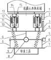
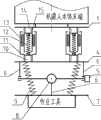
本发明所述的手腕包括摆动部分、移动部分、固定板、连接板、安装板、位移传感器和角度传感器,其具有三个自由度,其中所述的移动部分能够实现在一个方向上的移动,所述的摆动部分能够实现在两个方向上的摆动,具体结构如图1、图2所示,图1与图2分别为手腕在主视图与左视图上的剖视简图。The wrist of the present invention includes a swing part, a moving part, a fixed plate, a connecting plate, a mounting plate, a displacement sensor and an angle sensor, and it has three degrees of freedom, wherein the moving part can move in one direction, The swing part can swing in two directions, and its specific structure is shown in Fig. 1 and Fig. 2. Fig. 1 and Fig. 2 are schematic cross-sectional views of the wrist in front view and left view respectively.
所述的移动部分具有支承套结构,该支承套结构具有上支承套15、下支承套11、直线轴承13、调整螺塞14、10和弹簧12。固定板1固定在机器人本体末端,上支承套15通过调整螺塞14与固定板1联接,下支承套11通过调整螺塞10与连接板4联接起来,直线轴承13装在下支承套11内,上支承套15与直线轴承13可以作相对直线运动,调整螺塞14固定在固定板1上,又通过螺纹与上支承套15联接,调整螺塞10固定在连接板4上,又通过螺纹与下支承套11联接,弹簧12的两端分别固定在调整螺塞14、10上。当弹簧受拉力或压力时会伸长或缩短,从而带动下支承套11,进一步带动连接板4移动,当无外力作用时弹簧12使下支承套11及连接板4自动复位。一共有多对支承套结构来实现手腕的移动动作,图1、图2中是以4对支承套结构为例的。整个移动部分实现手腕沿一个方向移动及在无外力作用时自动复位的功能。位移传感器2安装在固定板1上,通过测量到安装在连接板4上的检测物3的距离获得手腕的移动量。The moving part has a supporting sleeve structure, and the supporting sleeve structure has an upper supporting
所述的摆动部分包括十字摆环8、四个小支架6、安装板7、四个斜置弹簧9。四个小支架6两两成对分别固定在连接板4及安装板7上,十字摆环8的四端分别与四个小支架6上的孔配合,两者可以相对转动,这样十字摆环8通过四个小支架6与连接板4及安装板7联接起来。四个斜置弹簧9均布地倾斜安装在连接板4及安装板7之间,限制十字摆环8在两个方向上的摆动幅度,并在无外力作用时使安装板7及十字摆环8自动复位,作业工具则安装在安装板7上。整个摆动部分实现手腕在两个方向上的摆动及无外力作用时自动复位的功能。两个角度传感器5分别安装在十字摆环8的相互垂直的两端上,用来测量十字摆环8绕其两轴线所摆动的角度。The swing part includes an
当安装在手腕上的作业工具碰到待加工的曲面时,手腕上的十字摆环8会绕其一轴线转动一定角度,安装板7会绕十字摆环8的另一轴线转动一定角度,装在十字摆环8上的两个角度传感器5会测量出十字摆环8分别绕其两轴线所摆动的角度,同时,安装板7受到作业对象轮廓朝外的力,迫使弹簧12压缩或拉伸,安装在固定板1上的位移传感器2会测量出弹簧压缩或拉伸所产生的位移量。将这些摆动角度和位移量反馈给机器人控制系统,系统会根据这些测量值自动调整机器人位姿使柔性手腕尽量恢复成平衡状态,这样可使柔性手腕处于工作平稳的状态,同时可以使角度偏转量与位移量控制在手腕允许的工作范围内。When the operating tool installed on the wrist touches the curved surface to be processed, the
根据作业的需要,手腕的移动部分和摆动部分可以调换位置,如图3所示,此时摆动部分安装在固定板1与连接板4之间,移动部分安装在连接板4与安装板7之间,固定板1安装在机器人本体上,安装板7上安装有作业工具。According to the needs of the work, the moving part and the swinging part of the wrist can be exchanged, as shown in Figure 3, at this time the swinging part is installed between the
Claims (8)
Priority Applications (1)
| Application Number | Priority Date | Filing Date | Title |
|---|---|---|---|
| CN2010102153145ACN101863035B (en) | 2010-07-02 | 2010-07-02 | Flexible waist for robot |
Applications Claiming Priority (1)
| Application Number | Priority Date | Filing Date | Title |
|---|---|---|---|
| CN2010102153145ACN101863035B (en) | 2010-07-02 | 2010-07-02 | Flexible waist for robot |
Publications (2)
| Publication Number | Publication Date |
|---|---|
| CN101863035Atrue CN101863035A (en) | 2010-10-20 |
| CN101863035B CN101863035B (en) | 2012-05-09 |
Family
ID=42955056
Family Applications (1)
| Application Number | Title | Priority Date | Filing Date |
|---|---|---|---|
| CN2010102153145AExpired - Fee RelatedCN101863035B (en) | 2010-07-02 | 2010-07-02 | Flexible waist for robot |
Country Status (1)
| Country | Link |
|---|---|
| CN (1) | CN101863035B (en) |
Cited By (29)
| Publication number | Priority date | Publication date | Assignee | Title |
|---|---|---|---|---|
| CN102107384A (en)* | 2010-12-21 | 2011-06-29 | 席文飞 | Automatic sanding and polishing device for industrial robot |
| CN102689312A (en)* | 2012-06-08 | 2012-09-26 | 常州大学 | Polishing robot mechanism |
| CN103028874A (en)* | 2013-01-10 | 2013-04-10 | 成都环龙智能系统设备有限公司 | Anti-collision mechanism |
| CN103128732A (en)* | 2013-01-28 | 2013-06-05 | 常州大学 | Parallel type adaptive surface processing operating arm mechanism |
| CN103203378A (en)* | 2012-01-11 | 2013-07-17 | 昆山允升吉光电科技有限公司 | Ultralimit-controllable linear stretching apparatus |
| CN103252777A (en)* | 2013-05-29 | 2013-08-21 | 金石机器人常州有限公司 | Manipulator capable of achieving automatic fine adjustment |
| CN103286791A (en)* | 2013-07-07 | 2013-09-11 | 林佳杰 | Robot joint structure |
| WO2014130353A1 (en)* | 2013-02-25 | 2014-08-28 | LuxVue Technology Corporation | Mass transfer tool manipulator assembly and micro pick up array mount with integrated displacement sensor |
| CN104385294A (en)* | 2014-11-17 | 2015-03-04 | 河北工业大学 | Flexible joint for joint robot |
| CN104626196A (en)* | 2014-12-12 | 2015-05-20 | 华北电力大学 | Changeable rigidity flexibility actuator |
| CN104772768A (en)* | 2015-02-11 | 2015-07-15 | 江南大学 | Bionic flexible wrist hand |
| US9095980B2 (en) | 2013-02-25 | 2015-08-04 | LuxVue Technology Corporation | Micro pick up array mount with integrated displacement sensor |
| US9308649B2 (en) | 2013-02-25 | 2016-04-12 | LuxVue Techonology Corporation | Mass transfer tool manipulator assembly |
| US9314930B2 (en) | 2012-12-14 | 2016-04-19 | LuxVue Technology Corporation | Micro pick up array with integrated pivot mount |
| US9391042B2 (en) | 2012-12-14 | 2016-07-12 | Apple Inc. | Micro device transfer system with pivot mount |
| CN106041917A (en)* | 2016-06-27 | 2016-10-26 | 武汉大学 | Planar self-adaptive locating mechanism for manipulator |
| US9624100B2 (en) | 2014-06-12 | 2017-04-18 | Apple Inc. | Micro pick up array pivot mount with integrated strain sensing elements |
| CN107150354A (en)* | 2017-05-24 | 2017-09-12 | 成都众智优学教育咨询有限公司 | A kind of wire spring compliant wrist |
| CN107186750A (en)* | 2017-05-24 | 2017-09-22 | 成都众智优学教育咨询有限公司 | The flat spring compliant wrist of manipulator |
| CN107618019A (en)* | 2017-08-04 | 2018-01-23 | 国网山东省电力公司电力科学研究院 | Mobile robot elastic component self-adapting flexible bindiny mechanism and detecting system |
| CN108673473A (en)* | 2018-06-06 | 2018-10-19 | 大连理工大学 | A kind of flexible mechanical arm configuration |
| CN109605338A (en)* | 2019-01-23 | 2019-04-12 | 北华大学 | Flexible Robot Arm Based on Ball Gear Transmission |
| CN109623868A (en)* | 2018-11-29 | 2019-04-16 | 清华大学 | Flexible adaptive device and mechanical arm |
| CN110549326A (en)* | 2018-05-30 | 2019-12-10 | 中国科学院沈阳自动化研究所 | robot grinding and polishing processing pose adjusting method based on multiple active compliant controllers |
| CN110919691A (en)* | 2019-12-31 | 2020-03-27 | 中国科学院沈阳自动化研究所 | A woodpecker-like underactuated joint and pecking device |
| CN112171700A (en)* | 2020-09-25 | 2021-01-05 | 江苏科技大学 | An adaptive manipulator for surface lamination of flexible materials |
| CN113910289A (en)* | 2021-09-02 | 2022-01-11 | 宁波巾山微型精密机器人有限公司 | a ring joint |
| CN113977626A (en)* | 2021-12-24 | 2022-01-28 | 季华实验室 | A tendon-driven bionic wrist joint based on tension structure |
| DE102020133102A1 (en) | 2020-12-11 | 2022-06-15 | Schaeffler Technologies AG & Co. KG | Impact protection safety device for robots |
Citations (10)
| Publication number | Priority date | Publication date | Assignee | Title |
|---|---|---|---|---|
| JPS6171282U (en)* | 1984-10-15 | 1986-05-15 | ||
| DE3716688A1 (en)* | 1986-06-04 | 1987-12-10 | Skoda Kp | Apparatus for performing three-dimensional movements |
| FR2619043A1 (en)* | 1987-08-05 | 1989-02-10 | Electricite De France | Grinding machine carrier with a pneumatic thrust cylinder for robot |
| JPH0994789A (en)* | 1995-09-29 | 1997-04-08 | Sekisui Chem Co Ltd | Compliance joint |
| CN2548766Y (en)* | 2002-06-27 | 2003-05-07 | 济南大学 | Polishing robot |
| US20040128850A1 (en)* | 2003-01-08 | 2004-07-08 | Sang-Wan Joo | Remote center compliance device |
| US20050194985A1 (en)* | 2004-02-20 | 2005-09-08 | Dr. Helmuth Heigl | Compliance module, particularly for a manipulator for positioning a test head, and one such manipulator |
| CN201033413Y (en)* | 2007-01-25 | 2008-03-12 | 江南大学 | Adaptive flexible polishing device for CNC milling machine with pressure regulation |
| CN101644610A (en)* | 2009-08-31 | 2010-02-10 | 内蒙古工业大学 | Pressure sensor |
| WO2010024794A1 (en)* | 2008-08-29 | 2010-03-04 | Abb Research Ltd. | Compliant apparatus for the tool at the end of an arm of an industrial robot |
- 2010
- 2010-07-02CNCN2010102153145Apatent/CN101863035B/ennot_activeExpired - Fee Related
Patent Citations (10)
| Publication number | Priority date | Publication date | Assignee | Title |
|---|---|---|---|---|
| JPS6171282U (en)* | 1984-10-15 | 1986-05-15 | ||
| DE3716688A1 (en)* | 1986-06-04 | 1987-12-10 | Skoda Kp | Apparatus for performing three-dimensional movements |
| FR2619043A1 (en)* | 1987-08-05 | 1989-02-10 | Electricite De France | Grinding machine carrier with a pneumatic thrust cylinder for robot |
| JPH0994789A (en)* | 1995-09-29 | 1997-04-08 | Sekisui Chem Co Ltd | Compliance joint |
| CN2548766Y (en)* | 2002-06-27 | 2003-05-07 | 济南大学 | Polishing robot |
| US20040128850A1 (en)* | 2003-01-08 | 2004-07-08 | Sang-Wan Joo | Remote center compliance device |
| US20050194985A1 (en)* | 2004-02-20 | 2005-09-08 | Dr. Helmuth Heigl | Compliance module, particularly for a manipulator for positioning a test head, and one such manipulator |
| CN201033413Y (en)* | 2007-01-25 | 2008-03-12 | 江南大学 | Adaptive flexible polishing device for CNC milling machine with pressure regulation |
| WO2010024794A1 (en)* | 2008-08-29 | 2010-03-04 | Abb Research Ltd. | Compliant apparatus for the tool at the end of an arm of an industrial robot |
| CN101644610A (en)* | 2009-08-31 | 2010-02-10 | 内蒙古工业大学 | Pressure sensor |
Cited By (45)
| Publication number | Priority date | Publication date | Assignee | Title |
|---|---|---|---|---|
| CN102107384A (en)* | 2010-12-21 | 2011-06-29 | 席文飞 | Automatic sanding and polishing device for industrial robot |
| CN102107384B (en)* | 2010-12-21 | 2013-06-26 | 席文飞 | Automatic sanding and polishing device for industrial robot |
| CN103203378A (en)* | 2012-01-11 | 2013-07-17 | 昆山允升吉光电科技有限公司 | Ultralimit-controllable linear stretching apparatus |
| CN103203378B (en)* | 2012-01-11 | 2015-09-23 | 昆山允升吉光电科技有限公司 | One transfinites controlled linear stretch device |
| CN102689312A (en)* | 2012-06-08 | 2012-09-26 | 常州大学 | Polishing robot mechanism |
| US9391042B2 (en) | 2012-12-14 | 2016-07-12 | Apple Inc. | Micro device transfer system with pivot mount |
| US9314930B2 (en) | 2012-12-14 | 2016-04-19 | LuxVue Technology Corporation | Micro pick up array with integrated pivot mount |
| US10043776B2 (en) | 2012-12-14 | 2018-08-07 | Apple Inc. | Micro device transfer system with pivot mount |
| CN103028874A (en)* | 2013-01-10 | 2013-04-10 | 成都环龙智能系统设备有限公司 | Anti-collision mechanism |
| CN103128732A (en)* | 2013-01-28 | 2013-06-05 | 常州大学 | Parallel type adaptive surface processing operating arm mechanism |
| CN105074899A (en)* | 2013-02-25 | 2015-11-18 | 勒克斯维科技公司 | Mass transfer tool manipulator assembly and micro pick up array mount with integrated displacement sensor |
| US9095980B2 (en) | 2013-02-25 | 2015-08-04 | LuxVue Technology Corporation | Micro pick up array mount with integrated displacement sensor |
| CN105074899B (en)* | 2013-02-25 | 2017-06-09 | 苹果公司 | Mass transfer tool manipulator assembly and micropickup array mount with integrated displacement sensors |
| WO2014130353A1 (en)* | 2013-02-25 | 2014-08-28 | LuxVue Technology Corporation | Mass transfer tool manipulator assembly and micro pick up array mount with integrated displacement sensor |
| US9308649B2 (en) | 2013-02-25 | 2016-04-12 | LuxVue Techonology Corporation | Mass transfer tool manipulator assembly |
| US10022859B2 (en) | 2013-02-25 | 2018-07-17 | Apple Inc. | Mass transfer tool manipulator assembly |
| CN103252777B (en)* | 2013-05-29 | 2015-02-04 | 金石机器人常州有限公司 | Manipulator capable of achieving automatic fine adjustment |
| CN103252777A (en)* | 2013-05-29 | 2013-08-21 | 金石机器人常州有限公司 | Manipulator capable of achieving automatic fine adjustment |
| CN103286791A (en)* | 2013-07-07 | 2013-09-11 | 林佳杰 | Robot joint structure |
| US10150669B2 (en) | 2014-06-12 | 2018-12-11 | Apple Inc. | Micro pick up array pivot mount |
| US9624100B2 (en) | 2014-06-12 | 2017-04-18 | Apple Inc. | Micro pick up array pivot mount with integrated strain sensing elements |
| CN104385294A (en)* | 2014-11-17 | 2015-03-04 | 河北工业大学 | Flexible joint for joint robot |
| CN104385294B (en)* | 2014-11-17 | 2016-02-03 | 河北工业大学 | A kind of flexible joint for revolute robot |
| CN104626196A (en)* | 2014-12-12 | 2015-05-20 | 华北电力大学 | Changeable rigidity flexibility actuator |
| CN104626196B (en)* | 2014-12-12 | 2015-12-09 | 华北电力大学 | A Variable Stiffness Flexible Actuator |
| CN104772768A (en)* | 2015-02-11 | 2015-07-15 | 江南大学 | Bionic flexible wrist hand |
| CN106041917A (en)* | 2016-06-27 | 2016-10-26 | 武汉大学 | Planar self-adaptive locating mechanism for manipulator |
| CN107186750A (en)* | 2017-05-24 | 2017-09-22 | 成都众智优学教育咨询有限公司 | The flat spring compliant wrist of manipulator |
| CN107150354A (en)* | 2017-05-24 | 2017-09-12 | 成都众智优学教育咨询有限公司 | A kind of wire spring compliant wrist |
| CN107618019A (en)* | 2017-08-04 | 2018-01-23 | 国网山东省电力公司电力科学研究院 | Mobile robot elastic component self-adapting flexible bindiny mechanism and detecting system |
| CN110549326A (en)* | 2018-05-30 | 2019-12-10 | 中国科学院沈阳自动化研究所 | robot grinding and polishing processing pose adjusting method based on multiple active compliant controllers |
| CN110549326B (en)* | 2018-05-30 | 2022-08-02 | 中国科学院沈阳自动化研究所 | Robotic grinding and polishing processing pose adjustment method based on multi-active compliance controller |
| CN108673473B (en)* | 2018-06-06 | 2021-03-26 | 大连理工大学 | Flexible mechanical arm structure |
| CN108673473A (en)* | 2018-06-06 | 2018-10-19 | 大连理工大学 | A kind of flexible mechanical arm configuration |
| CN109623868A (en)* | 2018-11-29 | 2019-04-16 | 清华大学 | Flexible adaptive device and mechanical arm |
| CN109605338A (en)* | 2019-01-23 | 2019-04-12 | 北华大学 | Flexible Robot Arm Based on Ball Gear Transmission |
| CN110919691A (en)* | 2019-12-31 | 2020-03-27 | 中国科学院沈阳自动化研究所 | A woodpecker-like underactuated joint and pecking device |
| CN110919691B (en)* | 2019-12-31 | 2023-07-28 | 中国科学院沈阳自动化研究所 | Under-actuated joint imitating woodpecker and pecking device |
| CN112171700B (en)* | 2020-09-25 | 2022-03-08 | 江苏科技大学 | Self-adaptive manipulator for curved surface laminating of flexible material |
| CN112171700A (en)* | 2020-09-25 | 2021-01-05 | 江苏科技大学 | An adaptive manipulator for surface lamination of flexible materials |
| DE102020133102A1 (en) | 2020-12-11 | 2022-06-15 | Schaeffler Technologies AG & Co. KG | Impact protection safety device for robots |
| CN113910289A (en)* | 2021-09-02 | 2022-01-11 | 宁波巾山微型精密机器人有限公司 | a ring joint |
| CN113910289B (en)* | 2021-09-02 | 2023-09-12 | 宁波巾山微型精密机器人有限公司 | a ring joint |
| CN113977626A (en)* | 2021-12-24 | 2022-01-28 | 季华实验室 | A tendon-driven bionic wrist joint based on tension structure |
| CN113977626B (en)* | 2021-12-24 | 2022-03-08 | 季华实验室 | A tendon-driven bionic wrist joint based on tension structure |
Also Published As
| Publication number | Publication date |
|---|---|
| CN101863035B (en) | 2012-05-09 |
Similar Documents
| Publication | Publication Date | Title |
|---|---|---|
| CN101863035B (en) | Flexible waist for robot | |
| US9829878B2 (en) | Robot, robot system, and robot control device | |
| JP6756166B2 (en) | Force sensor unit and robot | |
| CN106625653B (en) | Flexible docking method for industrial robot-assisted assembly based on force feedback | |
| CN105583824B (en) | Force control traction and swinging multi-degree-of-freedom mechanical arm control device and method | |
| KR101992149B1 (en) | Wearable Apparatus for measuring position and action of Arm | |
| CN207606868U (en) | A kind of simple activation lacking mechanical finger | |
| JP6996113B2 (en) | Robot control methods, robot systems and controls | |
| CN109986542A (en) | A rigid-flexible hybrid force-controlled end-effector driven by a gas-electric hybrid | |
| US9827670B1 (en) | Coaxial finger face and base encoding | |
| CN201824359U (en) | Flexible wrist for a robot | |
| JP5093498B2 (en) | Manipulator system | |
| TWI689389B (en) | Multiaxial robot | |
| KR101876676B1 (en) | 6-axis compliance device with force/torque sensing capability | |
| CN212218476U (en) | Torque controllable rotary drives and robotic systems | |
| US10773391B2 (en) | Control device and robot system | |
| KR101691941B1 (en) | Robot joint driving apparatus and joint torque measuring method of the same | |
| TWI765085B (en) | Robot hand, robot device, and manufacturing method of electronic machine | |
| JP2011062788A (en) | Manipulator device and method for controlling the same | |
| CN108714887B (en) | Spatial parallel mechanism with three degrees of freedom | |
| JP6136337B2 (en) | Attitude detection control apparatus, polishing apparatus, and attitude detection control method | |
| Garant et al. | Noncollocated proprioceptive sensing for lightweight flexible robotic manipulators | |
| CN104551468A (en) | Controllable mechanism-type mobile welding robot with five degrees of freedom | |
| CN208117874U (en) | A mechanical arm positioning device | |
| CN105673792B (en) | It is a kind of to measure the flexible gearing of output torque |
Legal Events
| Date | Code | Title | Description |
|---|---|---|---|
| C06 | Publication | ||
| PB01 | Publication | ||
| C10 | Entry into substantive examination | ||
| SE01 | Entry into force of request for substantive examination | ||
| C14 | Grant of patent or utility model | ||
| GR01 | Patent grant | ||
| CF01 | Termination of patent right due to non-payment of annual fee | Granted publication date:20120509 Termination date:20140702 | |
| EXPY | Termination of patent right or utility model |