CN101862543A - toy car - Google Patents
toy carDownload PDFInfo
- Publication number
- CN101862543A CN101862543ACN200910301557ACN200910301557ACN101862543ACN 101862543 ACN101862543 ACN 101862543ACN 200910301557 ACN200910301557 ACN 200910301557ACN 200910301557 ACN200910301557 ACN 200910301557ACN 101862543 ACN101862543 ACN 101862543A
- Authority
- CN
- China
- Prior art keywords
- toy car
- connecting portion
- hole
- projection
- roof
- Prior art date
- Legal status (The legal status is an assumption and is not a legal conclusion. Google has not performed a legal analysis and makes no representation as to the accuracy of the status listed.)
- Pending
Links
Images


Classifications
- A—HUMAN NECESSITIES
- A63—SPORTS; GAMES; AMUSEMENTS
- A63H—TOYS, e.g. TOPS, DOLLS, HOOPS OR BUILDING BLOCKS
- A63H17/00—Toy vehicles, e.g. with self-drive; ; Cranes, winches or the like; Accessories therefor
- A63H17/26—Details; Accessories
- A63H17/262—Chassis; Wheel mountings; Wheels; Axles; Suspensions; Fitting body portions to chassis
- A—HUMAN NECESSITIES
- A63—SPORTS; GAMES; AMUSEMENTS
- A63H—TOYS, e.g. TOPS, DOLLS, HOOPS OR BUILDING BLOCKS
- A63H17/00—Toy vehicles, e.g. with self-drive; ; Cranes, winches or the like; Accessories therefor
- A63H17/26—Details; Accessories
- A63H17/36—Steering-mechanisms for toy vehicles
Landscapes
- Toys (AREA)
Abstract
Translated fromChinese
Description
Translated fromChinese技术领域technical field
本发明涉及玩具领域,尤其涉及一种玩具车。The invention relates to the field of toys, in particular to a toy car.
背景技术Background technique
随着生活水平的提高,人们对儿童玩具,例如玩具车的品质要求越来越高,而行动的稳定性是衡量玩具车的品质的标准之一。通常地,玩具车包括车身,位于车身下方的底盘,以及装设于底盘上的车轮。对于底盘内仅装设有两个车轮的玩具车而言,由于玩具车与行动面之间仅有两个车轮作为触地点,玩具车行动时车身很难保持平衡,从而导致两轮玩具车的稳定性不高。With the improvement of living standards, people have higher and higher requirements on the quality of children's toys, such as toy cars, and the stability of movement is one of the criteria for measuring the quality of toy cars. Generally, a toy car includes a body, a chassis below the body, and wheels mounted on the chassis. For a toy car with only two wheels installed in the chassis, because there are only two wheels between the toy car and the action surface as the contact point, it is difficult for the body to maintain balance when the toy car is in action, resulting in a two-wheeled toy car. The stability is not high.
发明内容Contents of the invention
有鉴于此,有必要提供一种能够保持平衡且稳定性高的玩具车。In view of this, it is necessary to provide a toy car capable of maintaining balance and high stability.
一种玩具车,其包括一个底盘,一个位于该底盘上的车身,一个装设于该底盘上的车轮组件以及两个平衡组件。该低盘包括相对的第一面及第二面,该底盘开设有两个通孔。该车身位于第一面上。该车轮组件包括两个对称设置于该底盘上的车轮,以及两个分别驱动该车轮转动以使该玩具车行走的驱动件。所述两个平衡组件分别与所述两个通孔相对应。各平衡组件均包括一个导引件,一个触地件以及至少一个弹性件。该导引件固设于该第一面上且与该通孔相对应。该触地件穿设于该通孔且相对于该第二面突出,该触地件与该导引件相对应且滑动连接于该导引件。该至少一个弹性件位于该导引件与该触地件之间,且该至少一个弹性件的一端与该导引件抵触,另一端与该触地件抵触。A toy car comprises a chassis, a body on the chassis, a wheel assembly mounted on the chassis and two balance assemblies. The low plate includes opposite first and second faces, and the bottom plate is opened with two through holes. The body is located on the first side. The wheel assembly includes two wheels symmetrically arranged on the chassis, and two driving parts respectively driving the wheels to rotate to make the toy car walk. The two balance components correspond to the two through holes respectively. Each balance assembly includes a guide piece, a ground contact piece and at least one elastic piece. The guide is fixed on the first surface and corresponds to the through hole. The ground contact piece is passed through the through hole and protrudes relative to the second surface. The ground contact piece corresponds to the guide piece and is slidably connected to the guide piece. The at least one elastic member is located between the guide member and the ground contact member, and one end of the at least one elastic member interferes with the guide member, and the other end of the at least one elastic member interferes with the ground contact member.
与现有技术相比,本发明的玩具车的两个车轮及两个平衡组件作为该玩具车的四个触地点,使该玩具车在行走过程中底盘和车身保持平衡,提高了玩具车的稳定性。Compared with the prior art, the two wheels and two balance components of the toy car of the present invention are used as the four contact points of the toy car, so that the chassis and the body of the toy car are kept in balance during the walking process, and the stability of the toy car is improved. stability.
附图说明Description of drawings
图1是本发明第一实施方式提供的玩具车的立体组装图。Fig. 1 is a perspective assembly view of the toy car provided by the first embodiment of the present invention.
图2是图1的玩具车的部分立体分解图。FIG. 2 is a partially exploded perspective view of the toy vehicle of FIG. 1 .
图3是图1的玩具车的平衡组件的立体分解图。FIG. 3 is an exploded perspective view of a balance assembly of the toy vehicle of FIG. 1 .
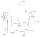
图4是图1的玩具车的导引件的立体放大图。Fig. 4 is an enlarged perspective view of the guide of the toy vehicle of Fig. 1 .
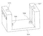
图5是本发明第二实施方式提供的玩具车的部分立体分解图。Fig. 5 is a partial perspective exploded view of the toy car provided by the second embodiment of the present invention.
图6是图5的玩具车的平衡组件的立体分解图。FIG. 6 is an exploded perspective view of the balance assembly of the toy vehicle of FIG. 5 .
图7是图6的玩具车的导引件的立体放大图。Fig. 7 is an enlarged perspective view of the guide of the toy car of Fig. 6 .
具体实施方式Detailed ways
下面将结合附图,对本发明作进一步的详细说明。The present invention will be further described in detail below in conjunction with the accompanying drawings.
请参阅图1及图2,为本发明第一实施方式提供的玩具车1。该玩具车1包括一个底盘10、一个位于该底盘10上的车身20、一个装设于该底盘10上的车轮组件30以及两个平衡组件40。Please refer to Fig. 1 and Fig. 2, which are the
请结合图3,该底盘10包括一个第一面12以及与该第一面12相对的第二面14。该底盘10开设有两个通孔16。该第一面12于该通孔16的周缘处凸设有三个第一卡合部122,三个与该第一卡合部122相对的第二卡合部124,两个相对且分设于所述三个第一卡合部122外侧的第一限位部126,以及两个相对且分设于所述三个第二卡合部124外侧的第二限位部128。该第一卡合部122与该第二卡合部124相对于该通孔16对称设置。Please refer to FIG. 3 , the
该车轮组件30包括两个对称设置于该底盘10上的车轮32,以及两个驱动件34。所述两个驱动件34分别驱动所述两个车轮32转动以使该玩具车1在行动面(图未示)上行走。The
所述两个平衡组件40分别与所述两个通孔16相对应,每个平衡组件40均包括一个固设于该第一面12上且与该通孔16相对应的导引件42,一个穿设于该通孔16且相对于该第二面14突出的触地件44,以及一个位于该导引件42与该触地件44之间的弹性件46。The two
请结合图4,该导引件42包括相对设置的第一侧壁420及第二侧壁422,以及垂直连接该第一侧壁420及该第二侧壁422并与该通孔16相对的顶壁424。该第一侧壁420远离该通孔16的一侧面开设有三个与该第一卡合部122相配合的第一卡槽421,该第一侧壁420接近该通孔16的一侧面开设有第一滑动槽423。该第二侧壁422远离该通孔16的一侧面开设有三个与该第二卡合部124相配合的第二卡槽425,该第二侧壁422接近该通孔16的一侧面开设有与该第一滑动槽423相对应的第二滑动槽427。该第一侧壁420抵触设置于所述两个第一限位部126之间且该第一卡合部122与该第一卡槽421卡合,以及该第二侧壁422抵触设置于所述两个第二限位部128之间且该第二卡合部124与该第二卡槽425卡合,从而使该导引件42固设于该第一面12上。该顶壁424朝向该触地件44的方向延伸有第一凸柱426。Please refer to FIG. 4 , the
可以理解,该导引件42固设于该第一面12上并不局限于本实施方式中的卡合方式,该导引件42还可以通过胶合方式、螺合方式或者焊接方式固设于该第一面12上。It can be understood that the fixing of the
请一并参阅图3及图4,该触地件44包括一个触地部440、一个支撑部442以及一个连接部444。该触地部440为一个半球体,其朝向该顶壁424的方向开设有一个收容腔441。该支撑部442开设有一个U形的凹槽443,该支撑部442固设于该收容腔441的底部。该连接部444包括相对设置的第一连接端444a及第二连接端444b。该连接部444朝向该顶壁424的方向延伸有第二凸柱446。该连接部444通过胶合方式固定连接于该凹槽443内。该第一连接端444a滑动设置于该第一滑动槽423内且与该第一面12抵触。该第二连接端444b滑动设置于该第二滑动槽427内且与该第一面12抵触。Please refer to FIG. 3 and FIG. 4 together, the
可以理解,该连接部444固定连接于该凹槽443内并不局限于本实施方式中的胶合方式,该连接部444还可以通过卡合方式或者焊接方式固定连接于该凹槽443内。It can be understood that the fixed connection of the connecting
该弹性件46为弹簧,其一端套设于该第一凸柱426且与该顶壁424抵触,另一端套设于该第二凸柱446且与该连接部444抵触。The
该驱动件34驱动该车轮32转动以使该玩具车1在行动面(图未示)上行走时,该车轮32及该平衡组件40均与地面接触以平衡底盘10和车身20。若该平衡组件40遇到障碍物,该连接部444挤压该弹性件46,该第一连接端444a沿着该第一滑动槽423滑动,该第二连接端444b沿着该第二滑动槽427滑动,从而使该触地件44朝接近该导引件42的顶壁424的方向运动以躲过障碍物。The driving
本发明的玩具车1的所述两个车轮32及所述两个平衡组件40作为该玩具车1的四个触地点,使该玩具车1在行走过程中底盘10和车身20保持平衡,提高了玩具车1的稳定性。The two
请参阅图5,为本发明第二实施方式提供的玩具车2。本实施方式的玩具车2与第一实施方式的玩具车1相比不同之处在于:Please refer to FIG. 5 , which shows the
请结合图7,该顶壁524朝向该触地件54延伸有一个第一凸柱526及一个第二凸柱528。Referring to FIG. 7 , the
请一并参阅图5及图6,该触地件54包括一个触地部540、一个第一支撑部542,一个第二支撑部544、一个第一连接部546以及一个第二连接部548。Please refer to FIG. 5 and FIG. 6 together, the ground-contacting member 54 includes a ground-contacting portion 540 , a first supporting portion 542 , a second supporting portion 544 , a first connecting portion 546 and a second connecting portion 548 .
该触地部540为一个半球体,其朝向该顶壁524的方向开设有一个收容腔541。该第一支撑部542及该第二支撑部544固设于该收容腔541的底部,该第一支撑部542开设有一个U形的第一凹槽543,该第二支撑部544开设有一个U形的第二凹槽545。该第一连接部546朝向该顶壁524的方向延伸有一个第三凸柱547,该第一连接部546的一端通过胶合方式固定连接于该第一凹槽543内,该第一连接部546的另一端滑动设置于该第一滑动槽523内且与该第一面12抵触。该第二连接部548朝向该顶壁524的方向延伸有一个第四凸柱549,该第二连接部548的一端通过胶合方式固定连接于该第二凹槽545内,该第二连接部548的另一端滑动设置于该第二滑动槽527内且与该第一面12抵触。The ground contact portion 540 is a hemisphere, and a receiving cavity 541 is opened toward the
该平衡组件50包括一个第一弹性件56及一个第二弹性件58。该第一弹性件56的一端套设于该第一凸柱526(图7示)且与该顶壁524抵触,另一端套设于该第三凸柱547且与该第一连接部546抵触。该第二弹性件58的一端套设于该第二凸柱528(图7示)且与该顶壁524抵触,另一端套设于该第四凸柱549且与该第二连接部548抵触。The balancing
该驱动件34驱动该车轮32转动以使该玩具车2在行动面(图未示)上行走时,该车轮32及该平衡组件50均与地面接触以平衡底盘10和车身20。若该平衡组件50遇到障碍物,该第一连接部546及该第二连接部548分别挤压该第一弹性件56及该第二弹性件58,该第一连接部546沿着该第一滑动槽523滑动,该第二连接部548沿着该第二滑动槽527(图7示)滑动,从而使该触地件54朝接近该顶壁524的方向运动以躲过障碍物。The driving
本发明的玩具车2的所述两个车轮32及所述两个平衡组件50作为该玩具车2的四个触地点,使该玩具车2在行走过程中底盘10和车身20保持平衡,提高了玩具车2的稳定性。The two
可以理解的是,对于本领域的普通技术人员来说,可以根据本发明的技术构思做出其它各种相应的改变与变形,而所有这些改变与变形都应属于本发明权利要求的保护范围。It can be understood that those skilled in the art can make various other corresponding changes and modifications according to the technical concept of the present invention, and all these changes and modifications should belong to the protection scope of the claims of the present invention.
Claims (12)
Priority Applications (2)
| Application Number | Priority Date | Filing Date | Title |
|---|---|---|---|
| CN200910301557ACN101862543A (en) | 2009-04-14 | 2009-04-14 | toy car |
| US12/491,250US8298039B2 (en) | 2009-04-14 | 2009-06-25 | Two-wheel toy car |
Applications Claiming Priority (1)
| Application Number | Priority Date | Filing Date | Title |
|---|---|---|---|
| CN200910301557ACN101862543A (en) | 2009-04-14 | 2009-04-14 | toy car |
Publications (1)
| Publication Number | Publication Date |
|---|---|
| CN101862543Atrue CN101862543A (en) | 2010-10-20 |
Family
ID=42934773
Family Applications (1)
| Application Number | Title | Priority Date | Filing Date |
|---|---|---|---|
| CN200910301557APendingCN101862543A (en) | 2009-04-14 | 2009-04-14 | toy car |
Country Status (2)
| Country | Link |
|---|---|
| US (1) | US8298039B2 (en) |
| CN (1) | CN101862543A (en) |
Families Citing this family (7)
| Publication number | Priority date | Publication date | Assignee | Title |
|---|---|---|---|---|
| US8814629B2 (en)* | 2011-06-21 | 2014-08-26 | Andrew Lewis Johnston | Non-rollable to rollable transforming toy |
| US20130307393A1 (en)* | 2012-05-21 | 2013-11-21 | Christopher Keith Bridges | Wheeled coaster |
| US9669322B2 (en)* | 2014-04-15 | 2017-06-06 | Tomy Company, Ltd. | Toy top |
| CN104841135B (en)* | 2015-05-12 | 2018-08-03 | 奥飞娱乐股份有限公司 | A kind of battle type gyro |
| FR3065208B1 (en)* | 2017-04-14 | 2021-04-16 | Exotec Solutions | AUTOMATIC GUIDING TROLLEY FOR TRANSPORTING AND / OR HANDLING A LOAD |
| USD922502S1 (en)* | 2017-07-05 | 2021-06-15 | Skip Hop, Inc. | Children's toy |
| KR20220067627A (en) | 2020-11-17 | 2022-05-25 | 삼성전자주식회사 | Moving robot apparatus and controlling method thereof |
Family Cites Families (46)
| Publication number | Priority date | Publication date | Assignee | Title |
|---|---|---|---|---|
| US2096333A (en)* | 1935-06-29 | 1937-10-19 | Marx Louis | Toy |
| US2121355A (en)* | 1937-04-28 | 1938-06-21 | Krupp Herman | Mechanical toy |
| US2770074A (en)* | 1953-09-03 | 1956-11-13 | Jones | Self propelled toy which circumvents obstructions |
| IT978377B (en)* | 1973-01-23 | 1974-09-20 | Folco Z | MOBILE STRUCTURE WITH ZERO CURVATURE RADIUS |
| US4161793A (en)* | 1975-11-03 | 1979-07-24 | Mercedes Merchan | Combination bathroom stool and toilet |
| US4034502A (en)* | 1976-09-07 | 1977-07-12 | Marvin Glass & Associates | Wheeled toy |
| US4223753A (en)* | 1977-12-19 | 1980-09-23 | Bradbury Harold M | Omni-directional transport device |
| GB2038615B (en)* | 1978-12-31 | 1983-04-13 | Nintendo Co Ltd | Self-moving type vacuum cleaner |
| US4290228A (en)* | 1980-02-13 | 1981-09-22 | Adolph E. Goldfarb | Toy vehicles with automatic banking |
| US4515235A (en)* | 1982-05-25 | 1985-05-07 | Shinko Electric Co., Ltd. | Driverless guided vehicle |
| JPS59105198U (en)* | 1982-12-28 | 1984-07-14 | 株式会社マツシロ | radio control lurk |
| US4702718A (en)* | 1986-02-05 | 1987-10-27 | Kaho Musen Limited | Controlled-drive toy |
| US4846758A (en)* | 1988-01-25 | 1989-07-11 | Chou Jin Long | Erratic toy vehicle with body tilt mechanism |
| US5019009A (en)* | 1990-03-12 | 1991-05-28 | Regency, Inc. | Toy car chassis intermittent tilt and steering structure |
| WO1993009018A1 (en)* | 1991-11-05 | 1993-05-13 | Seiko Epson Corporation | Micro-robot |
| JPH0838746A (en)* | 1994-07-27 | 1996-02-13 | Taiyo Kogyo Kk | Direction control device for radio control motorcycle toy |
| US5542872A (en)* | 1995-01-26 | 1996-08-06 | Ho; Tsai W. | Transmission mechanism of a toy motorcycle |
| US5549501A (en)* | 1995-06-07 | 1996-08-27 | Chain Fong Toys Co., Ltd. | Toy car with a liftable steering wheel assembly |
| US5618219A (en)* | 1995-12-22 | 1997-04-08 | Hasbro, Inc. | Remote control toy vehicle with driven jumper |
| GB2316013B (en)* | 1996-08-05 | 2000-03-15 | Wong T K Ass Ltd | Toy |
| JPH10260727A (en)* | 1997-03-21 | 1998-09-29 | Minolta Co Ltd | Automatic traveling working vehicle |
| US5868600A (en)* | 1997-04-21 | 1999-02-09 | Asahi Corporation | Toy car |
| US5839941A (en)* | 1997-08-26 | 1998-11-24 | Chen; Hwa-Lo | Toy car with a swinging unit which swings while the car is in motion |
| US5862703A (en)* | 1997-09-16 | 1999-01-26 | Tsai; Wen-Ho | Transmission mechanism for outward turning wheel set of toy car |
| US6152801A (en)* | 1999-07-07 | 2000-11-28 | Tsai; Wen-Ho | Toy car structure |
| AU1775401A (en)* | 1999-11-18 | 2001-05-30 | Procter & Gamble Company, The | Home cleaning robot |
| US8412377B2 (en)* | 2000-01-24 | 2013-04-02 | Irobot Corporation | Obstacle following sensor scheme for a mobile robot |
| US6481515B1 (en)* | 2000-05-30 | 2002-11-19 | The Procter & Gamble Company | Autonomous mobile surface treating apparatus |
| WO2002010000A1 (en)* | 2000-07-31 | 2002-02-07 | Hammonds Technical Services, Inc. | Omni direction vehicle |
| US7712556B2 (en)* | 2000-07-31 | 2010-05-11 | Hammonds Technical Services, Inc. | Omni direction vehicle |
| US7571511B2 (en)* | 2002-01-03 | 2009-08-11 | Irobot Corporation | Autonomous floor-cleaning robot |
| US6883201B2 (en)* | 2002-01-03 | 2005-04-26 | Irobot Corporation | Autonomous floor-cleaning robot |
| JP2003063462A (en)* | 2001-08-24 | 2003-03-05 | Kyosho Corp | Travel body |
| US6641457B1 (en)* | 2002-07-23 | 2003-11-04 | Aling Lai | Chassis of remotely controllable car |
| US7320149B1 (en)* | 2002-11-22 | 2008-01-22 | Bissell Homecare, Inc. | Robotic extraction cleaner with dusting pad |
| US7346428B1 (en)* | 2002-11-22 | 2008-03-18 | Bissell Homecare, Inc. | Robotic sweeper cleaner with dusting pad |
| AU2003900861A0 (en)* | 2003-02-26 | 2003-03-13 | Silverbrook Research Pty Ltd | Methods,systems and apparatus (NPS042) |
| CN1713939A (en)* | 2003-05-23 | 2005-12-28 | 尼科株式会社 | Radio-controlled toy two-wheeled vehicle |
| KR100507926B1 (en)* | 2003-06-30 | 2005-08-17 | 삼성광주전자 주식회사 | Device for driving of robot cleaner |
| US6988929B2 (en)* | 2004-01-12 | 2006-01-24 | Che Ming King Wong | Speed wheel |
| US7581611B1 (en)* | 2005-06-03 | 2009-09-01 | Rehco, Llc | Two-wheel vehicle with a tilt mechanism and stability mechanism |
| JP4417902B2 (en)* | 2005-10-31 | 2010-02-17 | 株式会社東芝 | Wheel moving robot |
| US8025551B2 (en)* | 2006-09-20 | 2011-09-27 | Mattel, Inc. | Multi-mode three wheeled toy vehicle |
| CN101618281B (en)* | 2008-06-30 | 2013-04-24 | 鸿富锦精密工业(深圳)有限公司 | Electronic toy |
| CN101664603A (en)* | 2008-09-05 | 2010-03-10 | 鸿富锦精密工业(深圳)有限公司 | Electronic toy |
| US8142254B1 (en)* | 2009-08-26 | 2012-03-27 | G2 Inventions, Llc | Toy vehicle |
- 2009
- 2009-04-14CNCN200910301557Apatent/CN101862543A/enactivePending
- 2009-06-25USUS12/491,250patent/US8298039B2/ennot_activeExpired - Fee Related
Also Published As
| Publication number | Publication date |
|---|---|
| US8298039B2 (en) | 2012-10-30 |
| US20100261407A1 (en) | 2010-10-14 |
Similar Documents
| Publication | Publication Date | Title |
|---|---|---|
| CN101862543A (en) | toy car | |
| US9795892B2 (en) | Toy car apparatus | |
| US20080242193A1 (en) | Toy Vehicle Booster and Track Set | |
| CN105730553A (en) | AGV chassis structure capable of adapting to ground deformation | |
| WO2007131207A3 (en) | Wheeled toy vehicles and playsets for use therewith | |
| CA2908596A1 (en) | Connected running toy | |
| KR101588555B1 (en) | Slide Type blackboard | |
| CN111989249A (en) | Force finger | |
| CN216562240U (en) | Elevator sedan-chair door linkage teaching device | |
| KR20150069315A (en) | Improved transform toy car | |
| JP3148376U (en) | Casters used for suitcases | |
| CN102518349B (en) | Concealed type guide device for door body | |
| CN108284909A (en) | A kind of perambulator | |
| CN113747957B (en) | Clearance compensation device for model automobile | |
| CN102343926B (en) | Hand-clamping prevention mechanism of baby carriage | |
| CN106697034A (en) | Shock-absorbing mechanism for children's vehicles | |
| KR101563467B1 (en) | Improved transform toy car | |
| EP1704076B8 (en) | Light vehicle comprising a swing axle | |
| CN207274814U (en) | A kind of new driving wheel damping and its automatic guided vehicle | |
| DE10327966A1 (en) | Wheeled undercarriage for toy top has wheels connected together by axle running in bush with stub axle engaging socket in bottom of top and one wheel is in frictional contact with surface on top | |
| CN210363200U (en) | Universal wheel for light AGV trolley | |
| CN206954291U (en) | Wheel body shock-proof structure of handcart | |
| CN208130113U (en) | A kind of shockproof vehicle body micro-adjusting mechanism of electric wheel-chair vehicle front-wheel | |
| CN223144113U (en) | Moving Toys | |
| CN204391953U (en) | A kind of electric machine casing |
Legal Events
| Date | Code | Title | Description |
|---|---|---|---|
| C06 | Publication | ||
| PB01 | Publication | ||
| C02 | Deemed withdrawal of patent application after publication (patent law 2001) | ||
| WD01 | Invention patent application deemed withdrawn after publication | Application publication date:20101020 |