CN101861124B - Puncture device - Google Patents
Puncture deviceDownload PDFInfo
- Publication number
- CN101861124B CN101861124BCN2008801162862ACN200880116286ACN101861124BCN 101861124 BCN101861124 BCN 101861124BCN 2008801162862 ACN2008801162862 ACN 2008801162862ACN 200880116286 ACN200880116286 ACN 200880116286ACN 101861124 BCN101861124 BCN 101861124B
- Authority
- CN
- China
- Prior art keywords
- mentioned
- puncture body
- puncture
- holding section
- reset components
- Prior art date
- Legal status (The legal status is an assumption and is not a legal conclusion. Google has not performed a legal analysis and makes no representation as to the accuracy of the status listed.)
- Active
Links
Images


Classifications
- A—HUMAN NECESSITIES
- A61—MEDICAL OR VETERINARY SCIENCE; HYGIENE
- A61B—DIAGNOSIS; SURGERY; IDENTIFICATION
- A61B5/00—Measuring for diagnostic purposes; Identification of persons
- A61B5/15—Devices for taking samples of blood
- A61B5/150007—Details
- A61B5/150175—Adjustment of penetration depth
- A61B5/150198—Depth adjustment mechanism at the proximal end of the carrier of the piercing element
- A—HUMAN NECESSITIES
- A61—MEDICAL OR VETERINARY SCIENCE; HYGIENE
- A61B—DIAGNOSIS; SURGERY; IDENTIFICATION
- A61B5/00—Measuring for diagnostic purposes; Identification of persons
- A61B5/15—Devices for taking samples of blood
- A61B5/150007—Details
- A61B5/150015—Source of blood
- A61B5/150022—Source of blood for capillary blood or interstitial fluid
- A—HUMAN NECESSITIES
- A61—MEDICAL OR VETERINARY SCIENCE; HYGIENE
- A61B—DIAGNOSIS; SURGERY; IDENTIFICATION
- A61B5/00—Measuring for diagnostic purposes; Identification of persons
- A61B5/15—Devices for taking samples of blood
- A61B5/150007—Details
- A61B5/150374—Details of piercing elements or protective means for preventing accidental injuries by such piercing elements
- A61B5/150381—Design of piercing elements
- A61B5/150412—Pointed piercing elements, e.g. needles, lancets for piercing the skin
- A—HUMAN NECESSITIES
- A61—MEDICAL OR VETERINARY SCIENCE; HYGIENE
- A61B—DIAGNOSIS; SURGERY; IDENTIFICATION
- A61B5/00—Measuring for diagnostic purposes; Identification of persons
- A61B5/15—Devices for taking samples of blood
- A61B5/150007—Details
- A61B5/150374—Details of piercing elements or protective means for preventing accidental injuries by such piercing elements
- A61B5/150381—Design of piercing elements
- A61B5/150503—Single-ended needles
- A—HUMAN NECESSITIES
- A61—MEDICAL OR VETERINARY SCIENCE; HYGIENE
- A61B—DIAGNOSIS; SURGERY; IDENTIFICATION
- A61B5/00—Measuring for diagnostic purposes; Identification of persons
- A61B5/15—Devices for taking samples of blood
- A61B5/150007—Details
- A61B5/150374—Details of piercing elements or protective means for preventing accidental injuries by such piercing elements
- A61B5/150534—Design of protective means for piercing elements for preventing accidental needle sticks, e.g. shields, caps, protectors, axially extensible sleeves, pivotable protective sleeves
- A61B5/150541—Breakable protectors, e.g. caps, shields or sleeves, i.e. protectors separated destructively, e.g. by breaking a connecting area
- A61B5/150549—Protectors removed by rotational movement, e.g. torsion or screwing
- A—HUMAN NECESSITIES
- A61—MEDICAL OR VETERINARY SCIENCE; HYGIENE
- A61B—DIAGNOSIS; SURGERY; IDENTIFICATION
- A61B5/00—Measuring for diagnostic purposes; Identification of persons
- A61B5/15—Devices for taking samples of blood
- A61B5/150007—Details
- A61B5/150374—Details of piercing elements or protective means for preventing accidental injuries by such piercing elements
- A61B5/150534—Design of protective means for piercing elements for preventing accidental needle sticks, e.g. shields, caps, protectors, axially extensible sleeves, pivotable protective sleeves
- A61B5/15058—Joining techniques used for protective means
- A61B5/150618—Integrally moulded protectors, e.g. protectors simultaneously moulded together with a further component, e.g. a hub, of the piercing element
- A—HUMAN NECESSITIES
- A61—MEDICAL OR VETERINARY SCIENCE; HYGIENE
- A61B—DIAGNOSIS; SURGERY; IDENTIFICATION
- A61B5/00—Measuring for diagnostic purposes; Identification of persons
- A61B5/15—Devices for taking samples of blood
- A61B5/150007—Details
- A61B5/150374—Details of piercing elements or protective means for preventing accidental injuries by such piercing elements
- A61B5/150534—Design of protective means for piercing elements for preventing accidental needle sticks, e.g. shields, caps, protectors, axially extensible sleeves, pivotable protective sleeves
- A61B5/150694—Procedure for removing protection means at the time of piercing
- A61B5/150717—Procedure for removing protection means at the time of piercing manually removed
- A—HUMAN NECESSITIES
- A61—MEDICAL OR VETERINARY SCIENCE; HYGIENE
- A61B—DIAGNOSIS; SURGERY; IDENTIFICATION
- A61B5/00—Measuring for diagnostic purposes; Identification of persons
- A61B5/15—Devices for taking samples of blood
- A61B5/151—Devices specially adapted for taking samples of capillary blood, e.g. by lancets, needles or blades
- A61B5/15101—Details
- A61B5/15103—Piercing procedure
- A61B5/15107—Piercing being assisted by a triggering mechanism
- A61B5/15113—Manually triggered, i.e. the triggering requires a deliberate action by the user such as pressing a drive button
- A—HUMAN NECESSITIES
- A61—MEDICAL OR VETERINARY SCIENCE; HYGIENE
- A61B—DIAGNOSIS; SURGERY; IDENTIFICATION
- A61B5/00—Measuring for diagnostic purposes; Identification of persons
- A61B5/15—Devices for taking samples of blood
- A61B5/151—Devices specially adapted for taking samples of capillary blood, e.g. by lancets, needles or blades
- A61B5/15101—Details
- A61B5/15115—Driving means for propelling the piercing element to pierce the skin, e.g. comprising mechanisms based on shape memory alloys, magnetism, solenoids, piezoelectric effect, biased elements, resilient elements, vacuum or compressed fluids
- A61B5/15117—Driving means for propelling the piercing element to pierce the skin, e.g. comprising mechanisms based on shape memory alloys, magnetism, solenoids, piezoelectric effect, biased elements, resilient elements, vacuum or compressed fluids comprising biased elements, resilient elements or a spring, e.g. a helical spring, leaf spring, or elastic strap
- A—HUMAN NECESSITIES
- A61—MEDICAL OR VETERINARY SCIENCE; HYGIENE
- A61B—DIAGNOSIS; SURGERY; IDENTIFICATION
- A61B5/00—Measuring for diagnostic purposes; Identification of persons
- A61B5/15—Devices for taking samples of blood
- A61B5/151—Devices specially adapted for taking samples of capillary blood, e.g. by lancets, needles or blades
- A61B5/15186—Devices loaded with a single lancet, i.e. a single lancet with or without a casing is loaded into a reusable drive device and then discarded after use; drive devices reloadable for multiple use
- A61B5/15188—Constructional features of reusable driving devices
- A61B5/1519—Constructional features of reusable driving devices comprising driving means, e.g. a spring, for propelling the piercing unit
- A—HUMAN NECESSITIES
- A61—MEDICAL OR VETERINARY SCIENCE; HYGIENE
- A61B—DIAGNOSIS; SURGERY; IDENTIFICATION
- A61B5/00—Measuring for diagnostic purposes; Identification of persons
- A61B5/15—Devices for taking samples of blood
- A61B5/151—Devices specially adapted for taking samples of capillary blood, e.g. by lancets, needles or blades
- A61B5/15186—Devices loaded with a single lancet, i.e. a single lancet with or without a casing is loaded into a reusable drive device and then discarded after use; drive devices reloadable for multiple use
- A61B5/15188—Constructional features of reusable driving devices
- A61B5/15192—Constructional features of reusable driving devices comprising driving means, e.g. a spring, for retracting the lancet unit into the driving device housing
- A61B5/15194—Constructional features of reusable driving devices comprising driving means, e.g. a spring, for retracting the lancet unit into the driving device housing fully automatically retracted, i.e. the retraction does not require a deliberate action by the user, e.g. by terminating the contact with the patient's skin
Landscapes
- Health & Medical Sciences (AREA)
- Life Sciences & Earth Sciences (AREA)
- Heart & Thoracic Surgery (AREA)
- Surgery (AREA)
- Biophysics (AREA)
- Pathology (AREA)
- Engineering & Computer Science (AREA)
- Biomedical Technology (AREA)
- Hematology (AREA)
- Medical Informatics (AREA)
- Molecular Biology (AREA)
- Physics & Mathematics (AREA)
- Animal Behavior & Ethology (AREA)
- General Health & Medical Sciences (AREA)
- Public Health (AREA)
- Veterinary Medicine (AREA)
- Dermatology (AREA)
- Measurement Of The Respiration, Hearing Ability, Form, And Blood Characteristics Of Living Organisms (AREA)
- Automatic Tool Replacement In Machine Tools (AREA)
Abstract
Description
Translated fromChinese技术领域technical field
本发明涉及在采集检查用的血液和其他的体液或组织的情况下,用于将穿刺体的顶端刺入皮肤的穿刺装置。 The present invention relates to a puncturing device for piercing the skin with the tip of a puncturing body when collecting blood and other body fluids or tissues for examination. the
背景技术Background technique
作为以往的穿刺装置的一个例子,在专利文献1中有所记载,表示于图12。在该图所示的穿刺装置B中,在壳体210内收容有穿刺体保持架220、前进用弹簧280、复位弹簧270和具有操作部230a的操作构件230。在操纵操作部230a使操作构件230朝箭头Rr方向后退时,穿刺体保持架220也后退,前进用弹簧280被压缩。因此,之后,利用前进用弹簧280的弹力,使穿刺体保持架220迅速地朝箭头Fr方向前进,能将穿刺体290的针290a刺入穿刺对象部位(省略图示)。由此,从上述穿刺对象部位产生出血,能够将该血液供于检查。在实施了上述的操作之后,复位弹簧270发挥使操作构件230回归至原先的待机位置的作用。此外,在壳体210的盖240被卸下的状态下,使操作构件230向前方移动时,该操作构件230的顶端部233向前方推压穿刺体290使该穿刺体290从穿刺体保持架220脱离。所以,卸下使用完的穿刺体290的作业变得容易。 An example of a conventional puncturing device is described in
不过,在上述的穿刺装置B中,在为了使使用完的穿刺体290从穿刺体保持架220脱离而使操作构件230前进的情况下,操作构件230之后不会自动回归成原先的待机位置。因此,使用者不得不通过操纵操作部230a使操作构件230回归成原先的待机位置,该操作较为麻烦。作为解决该问题的方法,一般认为另外设置追加的复位弹簧,用于在为了使穿刺体290从穿刺 体保持架220脱离而使操作构件230前进之后,使该操作构件230后退。可是,采用这样的方法会导致零件个数增加、构造变复杂、穿刺装置变大型和制造成本提高。 However, in the above-mentioned puncturing device B, when the
专利文献1:日本特开2000-262498号公报 Patent Document 1: Japanese Patent Laid-Open No. 2000-262498
发明内容Contents of the invention
本发明的目的在于提供一种能适当地防止或抑制上述这样的问题的穿刺装置。 An object of the present invention is to provide a puncturing device capable of appropriately preventing or suppressing the above-mentioned problems. the
为了解决上述的课题,本发明具有如下的技术方案。 In order to solve the above-mentioned problems, the present invention has the following means. the
由本发明提供的穿刺装置的特征在于,包括:壳体,其在顶端具有开口部;穿刺体保持架,其在该壳体内保持穿刺体,且能沿上述壳体的前后方向移动,以使该穿刺体能从远离上述开口部的后退位置朝向上述开口部前进;操作构件,其能够从规定的待机位置向第1方向和第2方向移动,且能够进行穿刺体后退用操作和穿刺体脱离用操作,该穿刺体后退用操作为了使上述穿刺体保持架后退而使上述穿刺体配置到上述后退位置,使该操作构件从上述待机位置向上述第2方向移动;该穿刺体脱离用操作为了将上述穿刺体推出到上述穿刺体保持架的前方,使该操作构件从上述待机位置向上述第1方向移动;复位构件,在实施了上述穿刺体后退用操作之后,使上述操作构件回归到上述待机位置,并且在实施了上述穿刺体脱离用操作之后,使上述操作构件回归到上述待机位置。 The puncturing device provided by the present invention is characterized in that it includes: a housing having an opening at the top; a puncturing body holder which holds the puncturing body in the housing and can move in the front-rear direction of the housing so that the The puncture body can advance toward the above-mentioned opening from a retracted position away from the above-mentioned opening; an operation member that can move from a predetermined standby position to a first direction and a second direction, and can perform an operation for retreating the puncture body and an operation for detaching the puncture body , the puncture body retracting operation is to move the puncture body holder backward to arrange the puncture body to the retreat position, and move the operating member from the standby position to the second direction; the puncture body detachment operation is to move the above The puncture body is pushed out to the front of the above-mentioned puncture body holder, so that the operation member is moved from the above-mentioned standby position to the above-mentioned first direction; the reset member is used to return the above-mentioned operation member to the above-mentioned standby position after the above-mentioned puncture body is retracted. , and after the operation for detaching the puncture body is performed, the operation member is returned to the standby position. the
优选上述复位构件还发挥在上述穿刺体前进而刺入穿刺对象部位之后、使上述穿刺体保持架后退的功能。 Preferably, the reset member also functions to retract the puncture body holder after the puncture body advances to puncture the puncture target site. the
优选上述复位构件具有弹性体。 Preferably, the return member has an elastic body. the
优选上述弹性体是压缩弹簧。 Preferably, the elastic body is a compression spring. the
优选本发明的该穿刺装置还包括:前侧和后侧的止挡件, 它们分别设于上述壳体的内部,且通过分别与上述复位构件的前端和后端抵接而限制该复位构件向前后方向移动;第1和第2卡合部,它们设于上述操作构件,且位于在上述前后方向上夹着上述复位构件的位置,在实施上述穿刺体后退用操作时,上述第1卡合部后退,上述复位构件在该第1卡合部和上述后侧的止挡件之间被压缩,从而在实施了上述穿刺体后退用操作之后,上述复位构件向前方推压上述第1卡合部,在实施上述穿刺体脱离用操作时,上述第2卡合部前进,上述复位构件在该第2卡合部和上述前侧的止挡件之间被压缩,从而在实施了上述穿刺体脱离用操作之后,上述复位构件向后方推压上述第2卡合部。 Preferably, the puncture device of the present invention further includes: front and rear stoppers, which are respectively arranged inside the above-mentioned casing, and limit the movement of the reset member by abutting against the front end and the rear end of the reset member respectively. Movement in the front-rear direction; the first and second engaging parts are provided on the above-mentioned operating member and are located at the position sandwiching the above-mentioned reset member in the above-mentioned front-rear direction. part retreats, and the reset member is compressed between the first engaging part and the rear stopper, so that after the operation for retracting the puncture body is performed, the reset member pushes the first engaging part forward. part, when performing the operation for disengaging the puncture body, the second engaging portion advances, and the reset member is compressed between the second engaging portion and the front stopper, so that the puncturing body is released. After the disengagement operation, the return member pushes the second engaging portion backward. the
优选的是,为了避免上述前侧的止挡件和上述第1卡合部中的一方和另一方产生干扰,在上述前侧的止挡件和上述第1卡合部中的一方上形成有在与上述前后方向交叉的方向上具有宽度的开口部,为了避免上述后侧的止挡件和上述第2卡合部中的一方和另一方产生干扰,在上述后侧的止挡件和上述第2卡合部中的一方上形成有在与上述前后方向交叉的方向上具有宽度的开口部。 Preferably, in order to avoid interference between one and the other of the above-mentioned front stopper and the above-mentioned first engaging portion, a There is an opening having a width in a direction intersecting with the front-rear direction. In order to avoid interference between the stopper on the rear side and the second engagement part, the stopper on the rear side and the An opening having a width in a direction intersecting the front-rear direction is formed in one of the second engaging portions. the
优选的是,上述第1和第2卡合部是从上述操作构件朝向上述复位构件突出的突起,上述穿刺体保持架的一部分位于上述操作构件和上述复位构件之间,在上述穿刺体保持架的上述一部分设有孔部,该孔部供上述第1和第2卡合部插入、且容许上述操作构件和上述穿刺体保持架彼此在上述前后方向上相对移动。 Preferably, the first and second engaging portions are protrusions protruding from the operating member toward the reset member, a part of the puncture body holder is located between the operation member and the reset member, and the puncture body holder The above-mentioned part of the puncture body is provided with a hole for inserting the first and second engaging parts and allowing the operation member and the puncture body holder to move relative to each other in the front-rear direction. the
优选的是,上述穿刺体保持架具有在上述穿刺体前进而刺入穿刺对象部位时、与上述复位构件的后端抵接而将上述复位构件压缩的抵接部,通过该抵接部将上述复位构件压缩,从而产生使上述穿刺体保持架后退的力。 Preferably, the puncture body holder has an abutment portion that abuts against the rear end of the reset member to compress the reset member when the puncture body advances to puncture the puncture target site, and the abutment portion compresses the reset member. The return member is compressed, thereby generating a force for retreating the above-mentioned puncture body holder. the
优选的是,为了避免上述抵接部与上述第2卡合部和上述后侧的止挡件产生干扰,上述抵接部相对于上述第2卡合部和上述后侧的止挡件在与上述前后方向交叉的方向上错开。 Preferably, in order to prevent the abutting portion from interfering with the second engaging portion and the rear stopper, the abutting portion is in contact with the second engaging portion and the rear stopper. The above-mentioned front and rear directions are shifted in a direction intersecting with each other. the
优选的是,上述壳体具有壳体主体和被安装在该壳体主体的顶端部上且形成有上述开口部的盖, Preferably, the housing has a housing main body and a cover that is attached to the top end of the housing main body and forms the opening,
在实施了上述穿刺体脱离用操作时,在上述穿刺体被从上述穿刺体保持架推出前,上述盖被上述操作构件推压而从上述壳体主体脱离。 When the operation for detaching the puncture body is performed, the cover is pushed by the operation member to be detached from the housing body before the puncture body is pushed out from the puncture body holder. the
为了防止上述盖从上述壳体主体脱离时落下,上述盖借助连结构件被连结在上述壳体主体上。 In order to prevent the cover from falling when detached from the case main body, the cover is connected to the case main body via a connecting member. the
本发明的其他的特征和优点,通过参照附图,说明以下的发明的实施方式,是更加显而易见的。 Other features and advantages of the present invention will become more apparent by describing the following embodiments of the invention with reference to the accompanying drawings. the
附图说明Description of drawings
图1是表示应用了本发明的穿刺装置的一个例子的外观图。 FIG. 1 is an external view showing an example of a puncturing device to which the present invention is applied. the
图2是图1所示的穿刺装置的分解立体图。 Fig. 2 is an exploded perspective view of the puncturing device shown in Fig. 1 . the
图3A是表示图1所示的穿刺装置的未使用时的状态的剖视图,图3B是示意性表示图3A的主要部分的俯视图。 3A is a cross-sectional view showing the puncturing device shown in FIG. 1 in an unused state, and FIG. 3B is a plan view schematically showing a main part of FIG. 3A . the
图4A和图4B是省略了图3A所示的穿刺装置的壳体的状态的立体图。 4A and 4B are perspective views of a state in which the housing of the puncturing device shown in FIG. 3A is omitted. the
图5是表示将穿刺体安装到图1所示的穿刺装置上的状态的剖视图。 Fig. 5 is a cross-sectional view showing a state in which the puncture body is attached to the puncture device shown in Fig. 1 . the
图6A是表示在图1所示的穿刺装置中,通过推压穿刺体使穿刺体配置在规定后退位置的状态的主要部分的剖视图,图6B是示意性表示图6A的主要部分的俯视图。 6A is a sectional view of main parts showing a state in which the puncture body is pushed to a predetermined retracted position in the puncture device shown in FIG. 1 , and FIG. 6B is a plan view schematically showing the main parts of FIG. 6A . the
图7A和图7B是省略了图6A所示的穿刺装置的壳体的状态的立体图。 7A and 7B are perspective views of a state in which the housing of the puncturing device shown in FIG. 6A is omitted. the
图8A是表示使穿刺体从图6A所示的状态朝向穿刺对象部位前进的状态的剖视图,图8B是示意性表示图8A的主要部分的俯视图。 8A is a cross-sectional view showing a state in which the puncture body is advanced from the state shown in FIG. 6A to the puncture target site, and FIG. 8B is a plan view schematically showing the main part of FIG. 8A . the
图9A是表示在图1所示的穿刺装置中,操纵操作构件而进行穿刺体后退用操作的情况的剖视图,图9B是示意性表示图9A的主要部分的俯视图。 9A is a cross-sectional view showing a state in which the puncture body is retracted by manipulating the operation member in the puncturing device shown in FIG. 1 , and FIG. 9B is a plan view schematically showing the main part of FIG. 9A . the
图10A是表示在图1所示的穿刺装置中,取出使用完的穿刺体的情况的剖视图,图10B是示意性表示图10A的主要部分的俯视图。 10A is a cross-sectional view showing a state in which a used puncture body is taken out of the puncture device shown in FIG. 1 , and FIG. 10B is a plan view schematically showing the main part of FIG. 10A . the
图11是示意性表示图1所示的穿刺装置的穿刺深度调整机构的主要部分说明图。 Fig. 11 is an explanatory view schematically showing a main part of a puncturing depth adjustment mechanism of the puncturing device shown in Fig. 1 . the
图12是表示以往技术的一个例子的剖视图。 Fig. 12 is a cross-sectional view showing an example of conventional technology. the
具体实施方式Detailed ways
以下,参照附图具体地说明本发明优选的实施方式。 Hereinafter, preferred embodiments of the present invention will be specifically described with reference to the drawings. the
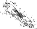
图1~图11表示应用有本发明的穿刺装置和与之相关的构成的一个例子。如图1所示,本实施方式的穿刺装置A具有在壳体1的外部设有操作部35、前进用按钮44、穿刺深度调整刻度盘5的结构。穿刺体9在树脂制的主体部90的顶端部设有金属制的针91,如后所述,穿刺体9被配置在壳体1内而使用。穿刺装置A是以从指尖、手臂等的皮肤S采集血液、测量该血液中的葡萄糖浓度为目的,用于将穿刺体9的针91刺入皮肤S(也参照图8A)。 1 to 11 show an example of a puncturing device to which the present invention is applied and its related configuration. As shown in FIG. 1 , the puncturing device A according to this embodiment has a structure in which an
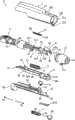
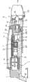
如图2所示,穿刺装置A除了壳体1之外,还包括辅助构件4、穿刺体保持架2、操作构件3、前进用弹簧8和复位构件7。在该穿刺装置A中,如后所述,在将穿刺体9保持在穿刺体保持架2上的状态下,使穿刺体保持架2向箭头N2所示方向后退后,按压前进用按钮44时,在前进用弹簧8的弹力作用下,穿刺体保持架2迅速地向箭头N1所示的方向前进,能够将穿刺体9的针91刺入使用者的皮肤S。操作构件3被利用在进行使穿刺体保持架2后退的操作和使穿刺动作结束之后使穿刺体9从穿刺体保持架2脱离的操作中。复位构件7发挥在操作构件3、穿刺体保持架2移动之后,使操作构件3、穿刺体保持架2回归到原先的待机位置的作用。以下,说明穿刺装置A的更加详细的构成。As shown in FIG. 2 , the puncturing device A includes, in addition to the
壳体1包括:大致筒状的壳体主体10;被安装在该壳体主体10的顶端部上的盖11。在盖11上形成有开口部11a。在壳体主体10的顶端的开口部102的内周形成有凸部104。相对于此,在盖11基端侧的筒部11b的外周形成有凹部11d。在将盖11的筒部11b嵌入开口部102时,通过凸部104和凹部11d卡合,能够防止盖11容易地从壳体主体10脱离。壳体主体10和盖11具有作为连结构件110的保持部103、11c,壳体主体10和盖11借助连结构件110互相连结。所以,如图5和图10A所示,能够防止盖11被从壳体主体10卸下时,盖11向下方落下。 The
如图2所示,辅助构件4包括:前进用按钮44;具有凹口43a的一对卡合部43;一对前侧的止挡件41A、41B;一对后侧的止挡件41C、41D。该辅助构件4设于壳体1内,且处于在前后方向上不能相对于壳体1移动的状态。但是,该辅助构件4当中的、设有前进用按钮44的靠近顶端的部分能在图2的上下方向位移。前进用按钮44经由设于壳体1的上壁部或侧壁部的开口部101露出到壳体1的外部,在按压该前进用按钮44时,一对卡合部43向图2的下方位移。如后所述,一对卡合部43是用于在穿刺体保持架2后退时、保持该后退的状态的部分。 As shown in FIG. 2 , the
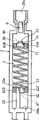
复位构件7是压缩弹簧,优选压缩螺旋弹簧。该复位构件7也可以代替压缩螺旋弹簧而使用橡胶或聚氨酯泡沫等弹性体构成。辅助构件4前侧和后侧的止挡件41A~41D呈向下的突起状,前侧的止挡件41A、41B和后侧的止挡件41C、41D之间的区域41为用于保持复位构件7的区域。前侧的止挡件41A、41B与复位构件7的前端71抵接,限制前端71向前方移动。后侧的止挡件41C、41D与复位构件7的后端72抵接,限制后端72向后方移动。在本发明中,也可以是前侧的止挡件41A、41B的侧面部和后侧的止挡件41C、41D的侧面部连接且一起构成为箱状。 The
穿刺体保持架2配置在辅助构件4和操作构件3之间,能够在壳体1的前后方向上移动。在该穿刺体保持架2上设有一对凸部23和用于保持穿刺体9的孔部26a。孔部26a设于穿刺体保持架2的顶端部,能使穿刺体9从该孔部26a的前方嵌入该孔部26a内。一对凸部23是在穿刺体保持架2后退时,通过与一对卡合部43卡合来用于保持穿刺体保持架2后退状态的部分(参照图5和图9A)。上述凸部23和卡合部43的卡合通过按压前进用按钮44而被解除。 The
前进用弹簧8是拉伸弹簧,其是在穿刺体保持架2后退的状态下、按压前进用按钮44时使该穿刺体保持架2朝向壳体1的前方迅速前进的构件。该前进用弹簧8的两端部81、82与设于辅助构件4和穿刺体保持架2上的卡合部45、24卡合(也参照图4A、图4B)。所以,在穿刺体保持架2相对于辅助构件4和壳体1向以箭头N2所示的方向后退时,前进用弹簧8伸长,处于能够发挥弹力的状态(也参照图6A、图7A、图7B)。 The advancing
在穿刺体保持架2的后部设有突起21,该突起21能与连续设置于穿刺深度调整刻度盘5的框架51抵接。更加详细地说,如图11所示,在框架51上形成有阶梯状排列的多个后面部51a,在穿刺体保持架2前进时,突起21与多个后面部51a中的某个抵 接,由此阻止穿刺体保持架2的前进。使穿刺深度调整刻度盘5旋转,使突起21与多个后面部51a中的某个抵接,从而能够调整穿刺体保持架2的前进行程,且能够调整穿刺体9相对于皮肤S的穿刺深度。 A
操作构件3具有凸状的操作部35,通过操纵该操作部35,能够使操作构件3沿壳体1的前后方向移动。作为利用了该操作构件3的操作,可以进行穿刺体后退用操作和穿刺体脱离用操作。上述穿刺体后退用操作是如下的操作,即,如图9A所示,使操作构件3从处于图3A所示的待机位置的状态向箭头N2的方向后退。在实施了该操作后,穿刺体保持架2也后退,能将穿刺体9配置到从盖11的开口部11a离开适当的距离的后退位置。上述穿刺体脱离用操作是如下的操作,即,如图10A所示,使操作构件3从位于图3A所示的待机位置的状态向箭头N1的方向前进。在实施了该操作后,盖11被从壳体主体10卸下,并且穿刺体9被从穿刺体保持架2推出。有关这些操作的详情如后所述。此外,使穿刺体9配置到上述后退位置的动作也可以不利用操作构件3,而利用穿刺体9推压穿刺体保持架2来进行,关于这一点也如后所述。 The
如图2所示,在操作构件3上设有作为朝上突起的第1和第2卡合部31、32。这些第1和第2卡合部31、32穿过形成于穿刺体保持架2的开口部28,在壳体1的前后方向上夹着复位构件7。更加具体来说,如图3B所示,第1和第2卡合部31、32位于复位构件7的前方和后方,能分别与复位构件7的前端71和后端72抵接。作为用于避免第1卡合部31和前侧的止挡件41A、41B干扰的方法,在前侧的止挡件41A、41B彼此之间形成有开口部46。同样,作为用于避免第2卡合部32和后侧的止挡件41C、41D的干扰的方法,在后侧的止挡件41C、41D彼此之间形成有开口部47。在操作构件3沿前后方向移动时,第1和第2卡合部31、32通过开口部46、47。 As shown in FIG. 2 , first and second engaging
在穿刺体保持架2上设有从开口部28的内壁的后面28a向前方突出的凸状部22。该凸状部22为了避免与后侧的止挡件41C、41D和第2卡合部32干扰,在壳体1的宽度方向上与止挡件41C、41D和第2卡合部32错开。该凸状部22的前端形成为能与复位构件7的后端72抵接的抵接部22a。如图8A和图8B所示,在使穿刺体保持架2和穿刺体9前进时,抵接部22a与复位构件7的后端72抵接,压缩复位构件7。 The
在穿刺体保持架2的靠近顶端的内部设有穿刺体推出用的可动构件6。如图10A和图10B所示,操纵操作构件3向箭头N1方向前进而使第1和第2卡合部31、32前进时,可动构件6被设于第1卡合部31的凸部33推向前方。结果,该可动构件6将穿刺体9从孔部26a向前方推出。优选可动构件6前进时,该可动构件6和穿刺体保持架2之间有适度的摩擦阻力,或将摩擦阻力设置成逐渐增加。采用这样的构成,能防止穿刺体9从孔部26a迅速飞出。 A
操作构件3的顶端部作为盖推出部34。该盖推出部34被设置成如下所述:在操纵操作构件3前进的情况下,在穿刺体9被从孔部26a推出的期间之前,该盖推出部34与盖11的后端面抵接,并且推压该后端面,从而使盖11从壳体主体10脱离。 The tip end portion of the
举出穿刺装置A的各部分的材质的具体例子,穿刺深度调整用刻度盘5、盖11和穿刺体保持架2是聚碳酸酯制品。辅助构件4、操作构件3和可动构件6是聚缩醛制品。壳体主体10是ABS树脂制品。当然,上述的各构件可以是聚乙烯、聚丙烯、聚苯乙烯等其他的树脂制品。连结构件110例如是热塑性弹性体制品,然而,也可以取而代之,使用天然橡胶、合成橡胶、聚碳酸酯、聚乙烯、聚丙烯、聚缩醛或聚苯乙烯等材质。穿刺体9的针91例如是不锈钢制品。主体部90的材质例如是聚乙烯、聚碳酸酯、聚丙烯、聚缩醛或聚苯乙烯。 As a specific example of the material of each part of the puncturing device A, the puncturing
接着,说明上述的穿刺装置A的使用例和作用。 Next, examples of use and functions of the above-mentioned puncturing device A will be described. the
首先,在图3A和图3B所示的未使用状态中,操作构件3存在于规定的待机位置。在该状态下,前进用弹簧8不伸长。复位构件7处于非压缩状态。随后,为了使用穿刺装置A,使穿刺体9保持在穿刺体保持架2上。如图5所示,该操作在从壳体主体10卸下了盖11的状态下通过使穿刺体9嵌入穿刺体保持架2的孔部26a来进行。优选在穿刺体9上设有覆盖针91的保护用的盖92。在使穿刺体9嵌入孔部26a的情况下,在将穿刺体9向箭头N2所示的后方推压时,能够使穿刺体保持架2克服前进用弹簧8的弹力向同方向后退。所以,在安装穿刺体9时,能不操纵操作构件3地将穿刺体9配置到规定的后退位置。此时,操作构件3仍停止在规定的待机位置。 First, in the unused state shown in FIGS. 3A and 3B , the
在进行了上述的操作之后,从穿刺体9卸下了盖92之后,将盖11安装在壳体主体10上。由此,如图6A所示,用于使穿刺体9和穿刺体保持架2前进的准备完成。在该状态下,前进用弹簧8伸长。此外,利用图5所示的凸部23和卡合部43的卡合,穿刺体保持架2的前进被阻止。如图6B所示,穿刺体保持架2相对于回归部件7、第1和第2卡合部31、32相对地后退,但是复位构件7仍为非压缩状态。 After the above-mentioned operations are performed, the
在图6A所示的状态下,操纵前进用按钮44时,如上所述的凸部23和卡合部43的卡合状态被解除,因此穿刺体保持架2在前进用弹簧8的弹力的作用下迅速前进。所以,如图8A所示,能够使穿刺体9的针91从盖11的开口部11a突出而刺入使用者的皮肤S。由此,能从皮肤S产生出血而采集血液。如上所述, 如图8B所示,在穿刺体保持架2前进时,抵接部22a与复位构件7的后端72抵接,使复位构件7压缩。所以,之后,穿刺体保持架2在复位构件7的弹力的作用下后退。结果,适当地避免针91仍从开口部11a突出的状态。 In the state shown in FIG. 6A , when the
在使穿刺体保持架2前进的情况下,有时因使用者的误操作等原因,无法适当地进行从皮肤S抽血,不得不再次进行穿刺动作。这样地进行第2次的穿刺动作的情况下,如图9A所示,操纵操作构件3的操作部35,使操作构件3向箭头N2的方向后退。在进行这样的操作时,如图9B所示,第2卡合部32与后面28a抵接,且将该部分向后方推压,穿刺体保持架2适当地后退。所以,前进用弹簧8伸长,且凸部23和卡合部43互相卡合,能使穿刺体9适当地配置到规定的后退位置。但是,在该情况下,第1卡合部31后退,将复位构件7的前端71朝向后方推压,因此复位构件7压缩。所以,在这样的状态下,按压前进用按钮44使穿刺体保持架2再次前进而进行穿刺动作时,之后,复位构件7将第1卡合部31向前方推压,发挥使操作构件3前进的弹力。结果,能够使操作构件3自动回归到原先的待机位置。 When advancing the puncturing
在能基于上述的穿刺动作适当地进行抽血之后,将穿刺体9取出到壳体1的外部。如图10A所示,该操作通过使操作构件3向箭头N1的方向前进来进行。这样地使操作构件3前进时,首先,操作构件3的顶端的盖推出部34与盖11的后端面抵接,将该盖11向壳体主体10的前方推出。盖11借助连结构件110与壳体主体10连结,所以适当地解决了盖11向下方落下而遗失这样的问题。随后,进一步使操作构件3前进时,如图10B所示,第1卡合部31借助可动构件6将穿刺体9的后端向前方推压。结果,穿刺体9被从穿刺体保持架2的孔部26a推出。在废弃穿刺体9时,预先使针91处于刺入保护用的盖92的侧部的状态。由此,能谋求防止误刺和防止感染。 After blood can be properly drawn based on the above-mentioned puncturing operation, the puncturing
如图10B所示,在上述的穿刺体9的推出动作时,第2卡合部32将复位构件7的后端72向前方推压,复位构件7压缩。因此,在上述的穿刺体9的推出动作后,复位构件7将第2卡合部32向后方推压,发挥使操作构件3后退的弹力。所以,操作构件3能自动回归到原先的待机位置。 As shown in FIG. 10B , during the push-out operation of the above-mentioned
这样,在该穿刺装置A中,在进行使操作构件3后退而将穿刺体9配置到规定的后退位置的操作、和使操作构件3前进而卸下穿刺体9的操作中的任一个的情况下,都能利用回归部构件7的弹力使操作构件3自动回归到原先的待机位置。所以,穿刺装置A便于使用。另一方面,在该穿刺装置A中,作为用于使操作构件3自动回归到原先的待机位置的复位构件而只使用了1个复位构件7,例如与设有该复位构件7和另外追加的复位弹簧的情况相比,能减少装置整体的零件个数,较佳地谋求构造的简化、小型化和制造成本的降低。特别是在该穿刺装置A中,穿刺体保持架2的一部分被安装在复位构件7和操作构件3之间,且设于操作构件3的第1和第2卡合部31、32在穿过穿刺体保持架2的开口部28的状态下与复位构件7的前端71和后端72抵接,因此能够空间利用率较高地配置这些构件。所以,对于促进穿刺装置A的小型化是更优选的。此外,在穿刺装置A中,使操作构件3前进时,除穿刺体9的卸下动作之外,也能进行盖11的卸下动作,所以使用更方便。 In this way, in this puncture device A, when either the operation of moving the
本发明不限定于上述的实施方式的内容。本发明的穿刺装置的各部分的具体构成能够进行各种设计变更。 The present invention is not limited to the contents of the above-mentioned embodiments. The specific configuration of each part of the puncturing device of the present invention can undergo various design changes. the
在本发明中所说的操作构件,也可以不作为单一构件而构成,例如可以是分开成用于使穿刺体保持架2后退的部分和用于推出穿刺体9的部分的这2个部分的构成。在本发明中所说的复位构件,如上述那样,也可以是利用压缩弹簧以外的弹性体。 The operating member mentioned in the present invention may not be constituted as a single member, for example, may be divided into two parts: a part for retreating the
Claims (8)
Applications Claiming Priority (3)
| Application Number | Priority Date | Filing Date | Title |
|---|---|---|---|
| JP2007297939 | 2007-11-16 | ||
| JP2007-297939 | 2007-11-16 | ||
| PCT/JP2008/070823WO2009063999A1 (en) | 2007-11-16 | 2008-11-15 | Puncture device |
Publications (2)
| Publication Number | Publication Date |
|---|---|
| CN101861124A CN101861124A (en) | 2010-10-13 |
| CN101861124Btrue CN101861124B (en) | 2012-05-30 |
Family
ID=40638845
Family Applications (1)
| Application Number | Title | Priority Date | Filing Date |
|---|---|---|---|
| CN2008801162862AActiveCN101861124B (en) | 2007-11-16 | 2008-11-15 | Puncture device |
Country Status (6)
| Country | Link |
|---|---|
| US (1) | US8323303B2 (en) |
| EP (1) | EP2220999B1 (en) |
| JP (1) | JP5190066B2 (en) |
| KR (1) | KR101147980B1 (en) |
| CN (1) | CN101861124B (en) |
| WO (1) | WO2009063999A1 (en) |
Families Citing this family (3)
| Publication number | Priority date | Publication date | Assignee | Title |
|---|---|---|---|---|
| JP5469397B2 (en)* | 2009-07-28 | 2014-04-16 | 泉株式会社 | Puncture device and lancet assembly and injector assembly constituting the same |
| PL234203B1 (en) | 2017-09-02 | 2020-01-31 | Htl Strefa Spolka Akcyjna | Device for puncturing of patient's skin |
| CN107854129B (en)* | 2017-10-23 | 2019-08-23 | 苏州施莱医疗器械有限公司 | A kind of blood collecting pen that paracentesis depth postposition is adjusted |
Citations (1)
| Publication number | Priority date | Publication date | Assignee | Title |
|---|---|---|---|---|
| CN1774209A (en)* | 2003-04-16 | 2006-05-17 | 爱科来株式会社 | Needle insertion device |
Family Cites Families (8)
| Publication number | Priority date | Publication date | Assignee | Title |
|---|---|---|---|---|
| US6197040B1 (en)* | 1999-02-23 | 2001-03-06 | Lifescan, Inc. | Lancing device having a releasable connector |
| EP1614382B1 (en)* | 2003-04-11 | 2012-07-11 | ARKRAY, Inc. | Needle insertion device |
| JP4500109B2 (en)* | 2004-06-04 | 2010-07-14 | パナソニック株式会社 | Puncture tool |
| KR100904106B1 (en) | 2005-04-28 | 2009-06-24 | 파나소닉 주식회사 | Needle insertion instrument and insertion needle cartridge |
| JP4536590B2 (en)* | 2005-05-16 | 2010-09-01 | パナソニック株式会社 | Puncture tool |
| US20060247670A1 (en)* | 2005-05-02 | 2006-11-02 | Levaughn Richard W | Lancing device with automatic lancet release |
| US20060247671A1 (en)* | 2005-05-02 | 2006-11-02 | Levaughn Richard W | Compact, multi-use micro-sampling device |
| JPWO2007088875A1 (en)* | 2006-02-01 | 2009-06-25 | アークレイ株式会社 | Lancet |
- 2008
- 2008-11-15WOPCT/JP2008/070823patent/WO2009063999A1/enactiveApplication Filing
- 2008-11-15JPJP2009541199Apatent/JP5190066B2/enactiveActive
- 2008-11-15KRKR1020107010612Apatent/KR101147980B1/enactiveActive
- 2008-11-15CNCN2008801162862Apatent/CN101861124B/enactiveActive
- 2008-11-15EPEP08849325Apatent/EP2220999B1/enactiveActive
- 2008-11-15USUS12/734,666patent/US8323303B2/enactiveActive
Patent Citations (1)
| Publication number | Priority date | Publication date | Assignee | Title |
|---|---|---|---|---|
| CN1774209A (en)* | 2003-04-16 | 2006-05-17 | 爱科来株式会社 | Needle insertion device |
Non-Patent Citations (3)
| Title |
|---|
| JP特开2000-262498A 2000.09.26 |
| JP特开2005-342324A 2005.12.15 |
| JP特开2006-314718A 2006.11.24 |
Also Published As
| Publication number | Publication date |
|---|---|
| US20100241149A1 (en) | 2010-09-23 |
| WO2009063999A1 (en) | 2009-05-22 |
| JPWO2009063999A1 (en) | 2011-03-31 |
| JP5190066B2 (en) | 2013-04-24 |
| KR101147980B1 (en) | 2012-05-24 |
| US8323303B2 (en) | 2012-12-04 |
| EP2220999A1 (en) | 2010-08-25 |
| KR20100072074A (en) | 2010-06-29 |
| CN101861124A (en) | 2010-10-13 |
| EP2220999B1 (en) | 2013-04-03 |
| EP2220999A4 (en) | 2012-01-11 |
Similar Documents
| Publication | Publication Date | Title |
|---|---|---|
| CN100443049C (en) | Lancet Components | |
| US7879059B2 (en) | Lancet assembly | |
| EP1913872A1 (en) | Needle insertion device, and lancet assembly and injector assembly that form the same | |
| CN102665551B (en) | Lancet pricking device | |
| JP2005111135A (en) | Lancet cassette and lancet projection device, and lancet assembly composed of these | |
| CN103169482A (en) | Lancet assembly and pricking device | |
| JPWO2007145204A1 (en) | Lancet assembly | |
| CN101861124B (en) | Puncture device | |
| JP5587721B2 (en) | Puncture device | |
| EP2601890A1 (en) | Lancet cartridge | |
| CN104510480B (en) | Sting device | |
| JP5469397B2 (en) | Puncture device and lancet assembly and injector assembly constituting the same | |
| CN111166349A (en) | Blood sampler | |
| JP4500109B2 (en) | Puncture tool | |
| HK1115521A (en) | Needle insertion device, and lancet assembly and injector assembly that form the same | |
| HK1096011A (en) | Lancet assembly | |
| HK1105854B (en) | Lancet assembly |
Legal Events
| Date | Code | Title | Description |
|---|---|---|---|
| C06 | Publication | ||
| PB01 | Publication | ||
| C10 | Entry into substantive examination | ||
| SE01 | Entry into force of request for substantive examination | ||
| C14 | Grant of patent or utility model | ||
| GR01 | Patent grant |