Movatterモバイル変換


[0]ホーム

URL:


CN101861024B - Centralized control dimming system of LED - Google Patents

Centralized control dimming system of LED
Download PDF

Info

Publication number
CN101861024B
CN101861024BCN2010101922022ACN201010192202ACN101861024BCN 101861024 BCN101861024 BCN 101861024BCN 2010101922022 ACN2010101922022 ACN 2010101922022ACN 201010192202 ACN201010192202 ACN 201010192202ACN 101861024 BCN101861024 BCN 101861024B
Authority
CN
China
Prior art keywords
output
converter
led
terminal
diode
Prior art date
Legal status (The legal status is an assumption and is not a legal conclusion. Google has not performed a legal analysis and makes no representation as to the accuracy of the status listed.)
Expired - Fee Related
Application number
CN2010101922022A
Other languages
Chinese (zh)
Other versions
CN101861024A (en
Inventor
葛良安
华桂潮
Current Assignee (The listed assignees may be inaccurate. Google has not performed a legal analysis and makes no representation or warranty as to the accuracy of the list.)
Huizhou Qianfeng Guangcai Technology Co ltd
Original Assignee
THINKLUX (Zhejiang) Lighting Tech Co Ltd
Priority date (The priority date is an assumption and is not a legal conclusion. Google has not performed a legal analysis and makes no representation as to the accuracy of the date listed.)
Filing date
Publication date
Application filed by THINKLUX (Zhejiang) Lighting Tech Co LtdfiledCriticalTHINKLUX (Zhejiang) Lighting Tech Co Ltd
Priority to CN2010101922022ApriorityCriticalpatent/CN101861024B/en
Publication of CN101861024ApublicationCriticalpatent/CN101861024A/en
Application grantedgrantedCritical
Publication of CN101861024BpublicationCriticalpatent/CN101861024B/en
Expired - Fee Relatedlegal-statusCriticalCurrent
Anticipated expirationlegal-statusCritical

Links

Images

Landscapes

Abstract

Translated fromChinese

本发明实施例提供一种LED的集中控制调光系统,包括:一AC-AC变换器,以及在AC-AC变换器与LED之间设置的AC-DC变换器;其中,所述AC-AC变换器的两个输入端连接交流电源,两个输出端分别与每路LED对应的AC-DC变换器的输入端连接,每个AC-DC变换器的输出端与对应的一路LED连接;所述AC-DC变换器根据所述AC-AC变换器输出的交流电压信号的特性参数值设置输出至对应至少一路的LED的驱动电流。由于该调光系统没有设置额外的调光信号线,所以整个系统的抗干扰能力较强,而且不受距离的限制,调光系统的可靠性更高。

Figure 201010192202

An embodiment of the present invention provides a centralized control dimming system for LEDs, including: an AC-AC converter, and an AC-DC converter arranged between the AC-AC converter and the LED; wherein, the AC-AC The two input terminals of the converter are connected to the AC power supply, the two output terminals are respectively connected to the input terminals of the AC-DC converter corresponding to each LED, and the output terminals of each AC-DC converter are connected to the corresponding LED; The AC-DC converter sets the driving current output to the corresponding at least one LED according to the characteristic parameter value of the AC voltage signal output by the AC-AC converter. Since the dimming system does not have an additional dimming signal line, the anti-interference ability of the whole system is strong, and it is not limited by distance, so the reliability of the dimming system is higher.

Figure 201010192202

Description

Translated fromChinese
一种LED的集中控制调光系统A centralized control dimming system for LED

技术领域technical field

本发明属于LED控制领域,尤其涉及一种LED的集中控制调光系统。The invention belongs to the field of LED control, in particular to a centralized control dimming system for LEDs.

背景技术Background technique

LED照明的突出优点在于节能和高光效,而且可以很容易地通过调节流过LED的电流实现调光的功能。The outstanding advantages of LED lighting are energy saving and high light efficiency, and the function of dimming can be easily realized by adjusting the current flowing through the LED.

图1示出了一种常用的通过外部调光器对LED进行调光的方案。其中,LED驱动器12上设置输入线11和输出线13,其中LED驱动器12通过输入线11连接电源,输出线13连接至LED,并为LED输出驱动电流。另外,LED驱动器12上还连接来自外部调光器的调光信号线,用户通过外部调光器可以调节输入到LED驱动器12中的调光信号,使得LED驱动器12根据调光信号输出至LED的驱动电流进行调节。Figure 1 shows a commonly used scheme for dimming LEDs through an external dimmer. Wherein, theLED driver 12 is provided with aninput line 11 and anoutput line 13, wherein theLED driver 12 is connected to a power supply through theinput line 11, and theoutput line 13 is connected to the LED, and outputs a driving current for the LED. In addition, the dimming signal line from the external dimmer is also connected to theLED driver 12, and the user can adjust the dimming signal input to theLED driver 12 through the external dimmer, so that theLED driver 12 outputs the dimming signal to the LED according to the dimming signal. The drive current is regulated.

但上述的调光方式需要为每个独立LED光源引入调光信号线14,不仅施工布线麻烦,而且当LED的距离较远需要延长调光信号线14的长度时,调光信号线也易受干扰,即随着调光信号线长度的延长,系统的可靠性也逐渐降低。However, the above-mentioned dimming method needs to introduce adimming signal line 14 for each independent LED light source, which is not only cumbersome for construction and wiring, but also when the distance between the LEDs is relatively long and the length of thedimming signal line 14 needs to be extended, the dimming signal line is also vulnerable. Interference, that is, with the extension of the length of the dimming signal line, the reliability of the system is gradually reduced.

发明内容Contents of the invention

有鉴于此,本发明的目的在于提供一种LED的集中控制调光系统,不需要额外的调光信号线,提高可靠性。In view of this, the object of the present invention is to provide a centralized control and dimming system for LEDs, which does not require additional dimming signal lines and improves reliability.

为实现上述目的,本发明提供一种LED的集中控制调光系统,包括:一AC-AC变换器,以及在AC-AC变换器与每路LED之间分别设置的AC-DC变换器;To achieve the above object, the present invention provides a centralized control dimming system for LEDs, comprising: an AC-AC converter, and an AC-DC converter respectively arranged between the AC-AC converter and each LED;

其中,所述AC-AC变换器的两个输入端连接交流电源,两个输出端分别与每路LED对应的AC-DC变换器的输入端连接,每个AC-DC变换器的输出端与对应的一路LED连接;Wherein, the two input terminals of the AC-AC converter are connected to the AC power supply, and the two output terminals are respectively connected to the input terminals of the AC-DC converter corresponding to each LED, and the output terminals of each AC-DC converter are connected to the AC power supply. Corresponding one LED connection;

所述AC-DC变换器根据所述AC-AC变换器输出的交流电压信号的特性参数值设置输出至对应一路的LED的驱动电流。The AC-DC converter sets the driving current output to a corresponding LED according to the characteristic parameter value of the AC voltage signal output by the AC-AC converter.

优选地,所述交流电压信号的特性参数值为交流电压信号的频率。Preferably, the characteristic parameter value of the AC voltage signal is the frequency of the AC voltage signal.

优选地,所述交流电压信号的特性参数值为交流电压信号的幅值。Preferably, the characteristic parameter value of the AC voltage signal is the amplitude of the AC voltage signal.

优选地,所述AC-AC变换器包括:驱动控制电路、第一开关管Q1和第二开关管Q2、第一二极管D1和第二二极管D2、第一电容C1和第二电容C2;Preferably, the AC-AC converter includes: a drive control circuit, a first switch tube Q1 and a second switch tube Q2, a first diode D1 and a second diode D2, a first capacitor C1 and a second capacitor C2;

其中,所述第一二极管D1的阳极和第二二极管D2的阴极连接交流电源的第一端,所述第一二极管D1的阴极连接所述第一电容C1的正端和所述第一开关管Q1的第一端,所述第二二极管D2的阳极连接所述第二电容C2的负端和第二开关管Q2的第二端,所述第一电容C1的负端和所述第二电容C2的正端相连,并连接交流电源的第二端和控制器输出电压的第二端;所述第一开关管Q1的第二端和所述第二开关管Q2的第一端相连,并连接控制器输出电压的第一端;所述驱动控制电路的两个信号输出端分别连接第一开关管Q1的第三端和第二开关管Q2的第三端。Wherein, the anode of the first diode D1 and the cathode of the second diode D2 are connected to the first terminal of the AC power supply, and the cathode of the first diode D1 is connected to the positive terminal of the first capacitor C1 and The first terminal of the first switching tube Q1, the anode of the second diode D2 are connected to the negative terminal of the second capacitor C2 and the second terminal of the second switching tube Q2, and the first terminal of the first capacitor C1 The negative terminal is connected to the positive terminal of the second capacitor C2, and is connected to the second terminal of the AC power supply and the second terminal of the output voltage of the controller; the second terminal of the first switching tube Q1 is connected to the second terminal of the second switching tube The first end of Q2 is connected to the first end of the output voltage of the controller; the two signal output ends of the drive control circuit are respectively connected to the third end of the first switching tube Q1 and the third end of the second switching tube Q2 .

优选地,所述AC-AC变换器包括:电感L、整流桥BD、第三开关管Q3、驱动控制电路、第一开关管Q1和第二开关管Q2、第一二极管D1和第二二极管D2、第一电容C1和第二电容C2;所述电感L的第一端连接交流电源的第一端,所述电感L的第二端连接第一二极管D1的阳极和第二二极管D2的阴极,所述第一二极管D1的阴极连接第一电容C1的正端和第一开关管Q1的第一端,所述第二二极管D2的阳极连接所述第二电容C2的负端和第二开关管Q2的第二端,所述第一电容C1的负端和第二电容C2的正端相连,并连接交流电源的第二端和控制器输出电压的第二端;所述第一开关管的第二端和第二开关管的第一端相连,并连接控制器输出电压的第一端;所述驱动控制电路的两个信号输出端分别连接第一开关管Q1的第三端和第二开关管Q2的第三端;Preferably, the AC-AC converter includes: an inductor L, a rectifier bridge BD, a third switch tube Q3, a drive control circuit, a first switch tube Q1 and a second switch tube Q2, a first diode D1 and a second switch tube Q3. Diode D2, first capacitor C1 and second capacitor C2; the first end of the inductor L is connected to the first end of the AC power supply, and the second end of the inductor L is connected to the anode of the first diode D1 and the second The cathode of the second diode D2, the cathode of the first diode D1 is connected to the positive end of the first capacitor C1 and the first end of the first switching tube Q1, and the anode of the second diode D2 is connected to the The negative terminal of the second capacitor C2 is connected to the second terminal of the second switching tube Q2, the negative terminal of the first capacitor C1 is connected to the positive terminal of the second capacitor C2, and is connected to the second terminal of the AC power supply and the output voltage of the controller the second end of the first switch tube; the second end of the first switch tube is connected to the first end of the second switch tube, and connected to the first end of the controller output voltage; the two signal output terminals of the drive control circuit are respectively connected to the third terminal of the first switching tube Q1 and the third terminal of the second switching tube Q2;

所述整流桥BD的两个交流输入端分别连接电感L的第二端和交流电源的第二端;所述整流桥BD的两个输出端分别连接第三开关管Q3的两端。The two AC input terminals of the rectifier bridge BD are respectively connected to the second terminal of the inductor L and the second terminal of the AC power supply; the two output terminals of the rectifier bridge BD are respectively connected to both ends of the third switching tube Q3.

优选地,所述AC-AC变换器包括:第三二极管D3和第四二极管D4、第一电感L1和第二电感L2、第一二极管D1和第二二极管D2、第一电容C1和第二电容C2,第一开关管Q1、第二开关管Q2、第四开关管Q4和第五开关管Q5、以及驱动控制电路;Preferably, the AC-AC converter includes: a third diode D3 and a fourth diode D4, a first inductor L1 and a second inductor L2, a first diode D1 and a second diode D2, The first capacitor C1 and the second capacitor C2, the first switching tube Q1, the second switching tube Q2, the fourth switching tube Q4 and the fifth switching tube Q5, and a drive control circuit;

其中,所述第三二极管D3的阳极和第四二极管D4的阴极与交流电源的第一端连接,所述第一电感L1的第一端与第三二极管D3的阴极连接,第二端与第四开关管Q4的第一端和第一二极管D1的阳极连接,所述第二电感L2的第一端连接第四二极管D4的阳极,第二端连接第四开关管Q4的第二端和第二二极管D2的阴极,第四开关管Q4的第二端与第五开关管Q5的第一端连接,并连接所述交流电源的第二端,所述第一二极管D1的阴极连接第一电容C1的正端和第一开关管Q1的第一端,所述第二二极管D2的阳极连接第二电容C2的负端和第二开关管Q2的第二端,第一电容C1的负端连接第二电容C2的正端,并连接所述交流电源的第二端和控制器输出电压的第二端,所述第一开关管Q1的第二端和第二开关管Q2的第一端连接,并连接控制器输出电压的第一端,所述驱动控制电路的两个信号输出端分别连接第一开关管Q1的第三端和第二开关管Q2的第三端。Wherein, the anode of the third diode D3 and the cathode of the fourth diode D4 are connected to the first end of the AC power supply, and the first end of the first inductor L1 is connected to the cathode of the third diode D3 , the second terminal is connected to the first terminal of the fourth switch tube Q4 and the anode of the first diode D1, the first terminal of the second inductor L2 is connected to the anode of the fourth diode D4, and the second terminal is connected to the anode of the first diode D4. The second end of the four switching tube Q4 is connected to the cathode of the second diode D2, the second end of the fourth switching tube Q4 is connected to the first end of the fifth switching tube Q5, and connected to the second end of the AC power supply, The cathode of the first diode D1 is connected to the positive terminal of the first capacitor C1 and the first terminal of the first switching tube Q1, and the anode of the second diode D2 is connected to the negative terminal of the second capacitor C2 and the second The second end of the switch tube Q2, the negative end of the first capacitor C1 is connected to the positive end of the second capacitor C2, and is connected to the second end of the AC power supply and the second end of the controller output voltage, the first switch tube The second terminal of Q1 is connected to the first terminal of the second switching tube Q2, and is connected to the first terminal of the output voltage of the controller, and the two signal output terminals of the drive control circuit are respectively connected to the third terminal of the first switching tube Q1 and the third terminal of the second switch tube Q2.

优选地,所述AC-DC变换器包括:Preferably, the AC-DC converter includes:

AC-DC变换主电路,用于将AC-AC变换器输出的交流电压信号进行变换,输出直流驱动电流;The AC-DC conversion main circuit is used to convert the AC voltage signal output by the AC-AC converter and output the DC drive current;

输入电压频率检测电路,用于检测所述AC-AC变换器输出的交流电压信号的频率,将检测的频率输出至第一输出电流控制电路;an input voltage frequency detection circuit, configured to detect the frequency of the AC voltage signal output by the AC-AC converter, and output the detected frequency to the first output current control circuit;

第一输出电流控制电路,用于根据接收到的频率值,向所述AC-DC变换主电路输出控制信号使其根据所述控制信号确定输出的驱动电流。The first output current control circuit is configured to output a control signal to the AC-DC conversion main circuit according to the received frequency value so that the output driving current can be determined according to the control signal.

优选地,所述AC-DC变换器包括:Preferably, the AC-DC converter includes:

AC-DC变换主电路,用于将从AC-AC变换器输出的交流电压信号进行变换,输出直流驱动电流;The AC-DC conversion main circuit is used to convert the AC voltage signal output from the AC-AC converter to output a DC drive current;

输入电压幅值检测电路,用于检测所述AC-AC变换器输出的交流电压信号的幅值,将检测的幅值输出至第二输出电流控制电路;The input voltage amplitude detection circuit is used to detect the amplitude of the AC voltage signal output by the AC-AC converter, and output the detected amplitude to the second output current control circuit;

第二输出电流控制电路,用于根据接收到的幅值,向所述AC-DC变换主电路输出控制信号使其根据控制信号确定输出的驱动电流。The second output current control circuit is configured to output a control signal to the AC-DC conversion main circuit so as to determine the output driving current according to the control signal according to the received amplitude.

由于本发明实施例中提供的LED的集中控制调光系统中调光信号是通过功率电压信号进行传递的,该功率电压信号不仅为系统中的各个部件提供电力,而且还可以由其得出调光控制信号,不需要另外设置由外部调光器输入驱动电路内的调光信号线。由于没有设置额外的调光信号线,所以整个系统的抗干扰能力较强,而且不受距离的限制,调光系统的可靠性更高。Since the dimming signal in the LED centralized control dimming system provided in the embodiment of the present invention is transmitted through the power voltage signal, the power voltage signal not only provides power for each component in the system, but also can obtain the dimming signal from it. The light control signal does not need to be additionally provided with a dimming signal line input into the drive circuit by an external dimmer. Since there is no additional dimming signal line, the anti-interference ability of the whole system is strong, and it is not limited by distance, so the reliability of the dimming system is higher.

本发明的AC-AC变换器和AC-DC变换器在整个灯具系统中可以分别独立放置。AC-AC变换器可作为集中式调光器,放置在灯具外面,AC-DC变换器可放置在灯具内部。由于大容量的电解电容只在AC-AC变换器中,而AC-AC变换器的位置可远离灯具热源,提高了大容量电解电容的寿命,从而大大提高系统可靠性。The AC-AC converter and the AC-DC converter of the present invention can be placed independently in the whole lighting system. The AC-AC converter can be used as a centralized dimmer and placed outside the luminaire, and the AC-DC converter can be placed inside the luminaire. Because the large-capacity electrolytic capacitor is only in the AC-AC converter, and the location of the AC-AC converter can be far away from the heat source of the lamp, the life of the large-capacity electrolytic capacitor is improved, thereby greatly improving system reliability.

附图说明Description of drawings

为了更清楚地说明本发明实施例或现有技术中的技术方案,下面将对实施例或现有技术描述中所需要使用的附图作简单地介绍,显而易见地,下面描述中的附图是本发明的一些实施例,对于本领域普通技术人员来讲,在不付出创造性劳动的前提下,还可以根据这些附图获得其他的附图。In order to more clearly illustrate the embodiments of the present invention or the technical solutions in the prior art, the following will briefly introduce the drawings that need to be used in the description of the embodiments or the prior art. Obviously, the accompanying drawings in the following description are For some embodiments of the present invention, those skilled in the art can also obtain other drawings based on these drawings without creative work.

图1是现有技术中通过外部调光器对LED进行调光的方案的示意图;FIG. 1 is a schematic diagram of a solution for dimming LEDs through an external dimmer in the prior art;

图2是本发明提供的LED的集中控制调光系统的一个实施例的示意图;Fig. 2 is the schematic diagram of an embodiment of the centralized control dimming system of LED provided by the present invention;

图3是图2中的AC-AC变换器输出的电压波形图;Fig. 3 is a voltage waveform diagram output by the AC-AC converter in Fig. 2;

图4是本发明提供的LED的集中控制调光系统的一个实施例中的AC-AC变换器的示意图;Fig. 4 is the schematic diagram of the AC-AC converter in one embodiment of the centralized control dimming system of LED provided by the present invention;

图5是本发明提供的LED的集中控制调光系统的另一个实施例中的AC-AC变换器的示意图;5 is a schematic diagram of an AC-AC converter in another embodiment of the centralized control and dimming system for LEDs provided by the present invention;

图6是本发明提供的LED的集中控制调光系统的另一个实施例中的AC-AC变换器的示意图;6 is a schematic diagram of an AC-AC converter in another embodiment of the centralized control and dimming system for LEDs provided by the present invention;

图7是本发明提供的LED的集中控制调光系统的另一个实施例中的AC-DC变换器的示意图;7 is a schematic diagram of an AC-DC converter in another embodiment of the centralized control dimming system for LEDs provided by the present invention;

图8是本发明提供的LED的集中控制调光系统的另一个实施例中的AC-DC变换器的示意图;8 is a schematic diagram of an AC-DC converter in another embodiment of the centralized control and dimming system of LEDs provided by the present invention;

图9是本发明提供的LED的集中控制调光系统的另一个实施例中的AC-DC变换器的示意图。Fig. 9 is a schematic diagram of an AC-DC converter in another embodiment of the LED centralized control dimming system provided by the present invention.

具体实施方式Detailed ways

为使本发明实施例的目的、技术方案和优点更加清楚,下面将结合本发明实施例中的附图,对本发明实施例中的技术方案进行清楚、完整地描述,显然,所描述的实施例是本发明一部分实施例,而不是全部的实施例。基于本发明中的实施例,本领域普通技术人员在没有做出创造性劳动前提下所获得的所有其他实施例,都属于本发明保护的范围。In order to make the purpose, technical solutions and advantages of the embodiments of the present invention clearer, the technical solutions in the embodiments of the present invention will be clearly and completely described below in conjunction with the drawings in the embodiments of the present invention. Obviously, the described embodiments It is a part of embodiments of the present invention, but not all embodiments. Based on the embodiments of the present invention, all other embodiments obtained by persons of ordinary skill in the art without making creative efforts belong to the protection scope of the present invention.

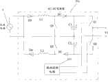
本发明的一个实施例提供一种LED的集中控制调光系统,如图2所示,该系统包括一AC-AC变换器21以及在AC-AC变换器21与每路LED4之间设置的AC-DC变换器22。其中,AC-AC变换器21的两个输入端连接交流电源3,两个输出端分别与每路LED4对应的AC-DC变换器22的输入端连接,每个AC-DC变换器22的输出端与对应的一路LED4连接。AC-AC变换器21的输出端输出如图3所示的方波交流电压,AC-DC变换器22用于根据该AC-AC变换器21输出的方波交流电压信号的特性参数值数值设置数值至对应一路的LED的驱动电流。One embodiment of the present invention provides a centralized control and dimming system for LEDs. As shown in FIG. -DC converter 22 . Wherein, the two input terminals of AC-AC converter 21 are connected withAC power supply 3, and the two output terminals are respectively connected with the input terminals of AC-DC converter 22 corresponding to each LED4, and the output of each AC-DC converter 22 The terminal is connected to the corresponding LED4. The output end of the AC-AC converter 21 outputs a square-wave AC voltage as shown in Figure 3, and the AC-DC converter 22 is used to set the characteristic parameter values of the square-wave AC voltage signal output according to the AC-AC converter 21 The value corresponds to the driving current of the LED of one channel.

本实施例中提供的LED的集中控制调光系统中传递的都是功率电压信号,而且根据功率电压信号本身即可对输出LED的驱动电流进行控制,不再另外设置外部调光器的调光信号,因此不易受干扰,并且不受距离的限制,可靠性高。另外,在AC-AC变换器和AC-DC变换器之间不需要防止复杂的信号发生装置和接收装置,结构简单,成本低。The LED centralized control dimming system provided in this embodiment transmits power and voltage signals, and the driving current of the output LED can be controlled according to the power voltage signal itself, and there is no need to additionally set the dimming of an external dimmer Signal, so it is not susceptible to interference, and is not limited by distance, with high reliability. In addition, there is no need to prevent complex signal generating devices and receiving devices between the AC-AC converter and the AC-DC converter, and the structure is simple and the cost is low.

上述方波交流电压信号的特性参数值可以为方波交流电压信号的频率,也可以是幅值。根据特性参数值选取的不同,相应的AC-AC变换器和AC-DC控制器也各不相同,以下以几个具体的实施例详细说明。The characteristic parameter value of the above-mentioned square-wave AC voltage signal may be the frequency or the amplitude of the square-wave AC voltage signal. Depending on the selection of characteristic parameter values, the corresponding AC-AC converters and AC-DC controllers are also different, and several specific embodiments are described in detail below.

图4示出了本发明提供的LED的集中控制系统的一个实施例中的AC-AC变换器的示意图。在本实施例中,AC-AC变换器21a包括驱动控制电路211、第一开关管Q1和第二开关管Q2、第一二极管D1和第二二极管d2、第一电容C1和第二电容C2,并且V1为控制器的输出电压。其中,第一二极管D1的阳极和第二二极管D2的阴极连接交流电源的第一端,第一二极管D1的阴极连接第一电容C1的正端和第一开关管Q1的第一端,第二二极管D2的阳极连接第二电容C2的负端和第二开关管Q2的第二端,第一电容C1的负端与第二电容C2的正端相连,并连接交流电源的第二端和控制器输出电压的第二端,第一开关管Q1的第二端与第二开关管Q2的第一端相连,并连接控制器输出电压的第一端;驱动控制电路211的两个信号输出端分别连接第一开关管Q1的第三端和第二开关管Q2的第三端。本实施例中的AC-AC变换器21a适用于方波交流电压信号的特性参数值取为频率的情形。Fig. 4 shows a schematic diagram of an AC-AC converter in an embodiment of the centralized LED control system provided by the present invention. In this embodiment, the AC-AC converter 21a includes adrive control circuit 211, a first switch tube Q1 and a second switch tube Q2, a first diode D1 and a second diode d2, a first capacitor C1 and a second capacitor C1. Two capacitors C2, and V1 is the output voltage of the controller. Wherein, the anode of the first diode D1 and the cathode of the second diode D2 are connected to the first terminal of the AC power supply, and the cathode of the first diode D1 is connected to the positive terminal of the first capacitor C1 and the terminal of the first switching tube Q1. The first terminal and the anode of the second diode D2 are connected to the negative terminal of the second capacitor C2 and the second terminal of the second switching tube Q2, the negative terminal of the first capacitor C1 is connected to the positive terminal of the second capacitor C2, and connected to The second end of the AC power supply and the second end of the controller output voltage, the second end of the first switching tube Q1 is connected to the first end of the second switching tube Q2, and connected to the first end of the controller output voltage; drive control The two signal output ends of thecircuit 211 are respectively connected to the third end of the first switching transistor Q1 and the third end of the second switching transistor Q2. The AC-AC converter 21a in this embodiment is suitable for the case where the characteristic parameter value of the square wave AC voltage signal is taken as the frequency.

在本实施例中,所述AC-AC变换器中,驱动控制电路控制第一开关管Q1和第二开关管Q2的开关状态。通过改变驱动控制的输出信号的周期,来改变开关管Q1和Q2的开关周期,从而改变输出电压V1的频率。图5示出了本发明提供的LED的集中控制调光系统的另一个实施例中的AC-AC变换器的示意图。该AC-AC变换器21b包括电感L、整流桥BD、第三开关管Q3、驱动控制电路211、第一开关管Q1和第二开关管Q2、第一二极管D1和第二二极管D2、第一电容C1和第二电容C2,控制器输出电压仍然为V1。其中,电感L的第一端连接交流电源3的第一端,电感L的第二端连接第一二极管D1的阳极和第二二极管D2的阴极,第一二极管D1的阴极连接第一电容C1的正端和第一开关管Q1的第一端,第二二极管D2的阳极连接第二电容C2的负端和第二开关管Q2的第二端;第一电容C1的负端与第二电容C2的正端相连,并连接交流电源3的第二端和控制器输出电压V1的第二端,第一开关管Q1的第二端和第二开关管Q2的第一端相连,并连接控制器输出电压V1的第一端,驱动控制电路211的两个信号输出端分别连接第一开关管Q1的第三端和第二开关管Q2的第三端。驱动控制电路,用于输出驱动信号,控制开关管Q1和Q2的通断。In this embodiment, in the AC-AC converter, the drive control circuit controls the switching states of the first switching tube Q1 and the second switching tube Q2. By changing the cycle of the output signal of the driving control, the switching cycle of the switching tubes Q1 and Q2 is changed, thereby changing the frequency of the output voltage V1. Fig. 5 shows a schematic diagram of an AC-AC converter in another embodiment of the LED centralized control dimming system provided by the present invention. The AC-AC converter 21b includes an inductor L, a rectifier bridge BD, a third switch tube Q3, adrive control circuit 211, a first switch tube Q1 and a second switch tube Q2, a first diode D1 and a second diode D2, the first capacitor C1 and the second capacitor C2, the output voltage of the controller is still V1. Wherein, the first end of the inductance L is connected to the first end of theAC power supply 3, the second end of the inductance L is connected to the anode of the first diode D1 and the cathode of the second diode D2, and the cathode of the first diode D1 The positive terminal of the first capacitor C1 is connected to the first terminal of the first switching tube Q1, and the anode of the second diode D2 is connected to the negative terminal of the second capacitor C2 and the second terminal of the second switching tube Q2; the first capacitor C1 The negative terminal of the second capacitor C2 is connected to the positive terminal of the second capacitor C2, and is connected to the second terminal of theAC power supply 3 and the second terminal of the controller output voltage V1, the second terminal of the first switching tube Q1 and the second terminal of the second switching tube Q2 One end is connected to the first end of the controller output voltage V1, and the two signal output ends of the drivingcontrol circuit 211 are respectively connected to the third end of the first switch Q1 and the third end of the second switch Q2. The driving control circuit is used for outputting driving signals to control the on-off of the switching tubes Q1 and Q2.

整流桥BD的两个交流输入端分别连接电感L的第二端和交流电源3的第二端,整流桥BD的两个输出端分别连接第三开关管Q3的两端。当第三开关管Q3导通时,输入交流电源通过整流桥BD为电感L储能,当第三开关管Q3关断时,输入交流电源通过二极管D1或二极管D2为后级电路输出能量,同时电感L释放能量;这样,通过控制开关管Q3的工作状态可控制输出电压V1的幅值。The two AC input terminals of the rectifier bridge BD are respectively connected to the second terminal of the inductor L and the second terminal of theAC power supply 3, and the two output terminals of the rectifier bridge BD are respectively connected to both ends of the third switching tube Q3. When the third switching tube Q3 is turned on, the input AC power stores energy for the inductor L through the rectifier bridge BD; when the third switching tube Q3 is turned off, the input AC power outputs energy for the subsequent circuit through the diode D1 or diode D2, and at the same time The inductor L releases energy; thus, the amplitude of the output voltage V1 can be controlled by controlling the working state of the switch tube Q3.

本实施例中的AC-AC变换器21b适用于方波交流电压信号的特性参数值取为频率或幅值的情形。在本实施例中,驱动控制电路通过控制开关管Q1和Q2的开关状态,来改变输出电压V1的方波交流电压的频率(与图4实施例所述的原理相同);通过控制第三开关管Q3的开关状态,控制电感L的储能能量,从而改变第一电容C1和第二电容C2上的电压幅值,即可改变输出电压V1的幅值。The AC-AC converter 21b in this embodiment is suitable for the case where the characteristic parameter value of the square wave AC voltage signal is frequency or amplitude. In this embodiment, the drive control circuit changes the frequency of the square wave AC voltage of the output voltage V1 by controlling the switching states of the switching tubes Q1 and Q2 (the principle is the same as that described in the embodiment of FIG. 4 ); by controlling the third switch The switch state of the tube Q3 controls the energy storage energy of the inductor L, thereby changing the voltage amplitudes on the first capacitor C1 and the second capacitor C2, thereby changing the amplitude of the output voltage V1.

图6示出了本发明提供的LED的集中控制调光系统的再一个实施例中的AC-AC变换器的示意图。该AC-AC变换器21c包括第三二极管D3和第四二极管D4、第一电感L1和第二电感L2、第一二极管D1和第二二极管D2、第一电容C1和第二电容C2、第一开关管Q1和第二开关管Q2、第四开关管Q4和第五开关管Q5、以及驱动控制电路211,控制器输出电压为V1。其中,第三二极管D3和阳极和第四二极管D4的阴极与交流电源3的第一端连接,第一电感L1的第一端与第三二极管D3的阴极相连,第二端与第一二极管D1的阳极和第四开关管Q4的第一端连接,第二电感L2的第一端连接第四二极管D4的阳极,第二电感L2的第二端与第四开关管Q4的第二端和第二二极管D2的阴极相连,第四开关管Q4的第二端和第五开关管Q5的第一端相连,并连接交流电源3的第二端,第一二极管D1的阴极连接第一电容C1的正端和第一开关管Q1的第一端,第二二极管D2的阳极连接第二电容C2的负端和第二开关管Q2的第二端,第一电容C1的负端与第二电容C2的正端相连,并连接交流电源3的第二端和控制器输出电压V1的第二端,第一开关管Q1的第二端与第二开关管Q2的第一端相连,并连接控制器输出电压V1的第一端。驱动控制电路211的两个信号输出端分别连接第一开关管Q1的第三端和第二开关管Q2的第三端。驱动控制电路,用于输出驱动信号,控制开关管Q1和Q2的通断。Fig. 6 shows a schematic diagram of an AC-AC converter in yet another embodiment of the LED centralized control dimming system provided by the present invention. The AC-AC converter 21c includes a third diode D3 and a fourth diode D4, a first inductor L1 and a second inductor L2, a first diode D1 and a second diode D2, and a first capacitor C1 And the second capacitor C2, the first switching tube Q1 and the second switching tube Q2, the fourth switching tube Q4 and the fifth switching tube Q5, and the drivingcontrol circuit 211, the output voltage of the controller is V1. Wherein, the anode of the third diode D3 and the cathode of the fourth diode D4 are connected to the first end of theAC power supply 3, the first end of the first inductance L1 is connected to the cathode of the third diode D3, and the second end is connected with the anode of the first diode D1 and the first end of the fourth switching tube Q4, the first end of the second inductance L2 is connected with the anode of the fourth diode D4, and the second end of the second inductance L2 is connected with the first end of the fourth switching tube Q4. The second end of the four switching tube Q4 is connected to the cathode of the second diode D2, the second end of the fourth switching tube Q4 is connected to the first end of the fifth switching tube Q5, and connected to the second end of theAC power supply 3, The cathode of the first diode D1 is connected to the positive terminal of the first capacitor C1 and the first terminal of the first switching tube Q1, and the anode of the second diode D2 is connected to the negative terminal of the second capacitor C2 and the terminal of the second switching tube Q2. The second terminal, the negative terminal of the first capacitor C1 is connected to the positive terminal of the second capacitor C2, and is connected to the second terminal of theAC power supply 3 and the second terminal of the controller output voltage V1, and the second terminal of the first switching tube Q1 It is connected with the first end of the second switch tube Q2 and connected with the first end of the controller output voltage V1. The two signal output terminals of thedrive control circuit 211 are respectively connected to the third terminal of the first switching transistor Q1 and the third terminal of the second switching transistor Q2. The driving control circuit is used for outputting driving signals to control the on-off of the switching tubes Q1 and Q2.

本实施例中的AC-AC变换器21c适用于方波交流电压信号的特性参数值取为频率或幅值的情形。在本实施例中,驱动控制电路通过控制开关管Q1和Q2的开关状态,来改变输出电压V1的方波交流电压的频率(与图4实施例所述的原理相同);通过控制第四开关管Q4和第五开关管Q5的开关状态,控制第一电感L1和第二电感L2的储能能量,从而改变第一电容C1和第二电容C2上的电压幅值,即可改变输出电压V1的幅值。The AC-AC converter 21c in this embodiment is suitable for the case where the characteristic parameter value of the square wave AC voltage signal is frequency or amplitude. In this embodiment, the drive control circuit changes the frequency of the square wave AC voltage of the output voltage V1 by controlling the switching states of the switching tubes Q1 and Q2 (the principle is the same as that described in the embodiment of FIG. 4 ); by controlling the fourth switch The switching states of the tube Q4 and the fifth switching tube Q5 control the energy storage energy of the first inductor L1 and the second inductor L2, thereby changing the voltage amplitudes on the first capacitor C1 and the second capacitor C2, thereby changing the output voltage V1 the magnitude of .

图7为本发明提供的LED的集中控制调光系统的另一个实施例中的AC-DC变换器的结构示意图。该AC-DC变换器22a适用于方波交流电压信号的特性参数取为频率的情形,具体地,包括:AC-DC变换主电路221、输入电压频率检测电路222和第一输出电流控制电路223。其中,AC-DC变换主电路221将AC-AC变换器输出的方波交流电压信号进行变换,输出直流驱动电流,输入电压频率检测电路222检测AC-AC变换器输出的方波交流电压信号的频率,并将检测到的频率输出至第一输出电流控制电路223,第一输出电流控制电路223根据接收到的频率值,向AC-DC变换主电路221输出控制信号,以使AC-DC变换主电路221根据该控制信号确定输出的驱动电流。FIG. 7 is a schematic structural diagram of an AC-DC converter in another embodiment of the centralized control and dimming system for LEDs provided by the present invention. The AC-DC converter 22a is suitable for the situation where the characteristic parameter of the square wave AC voltage signal is taken as the frequency, and specifically includes: an AC-DC conversionmain circuit 221, an input voltagefrequency detection circuit 222 and a first outputcurrent control circuit 223 . Among them, the AC-DC conversionmain circuit 221 converts the square-wave AC voltage signal output by the AC-AC converter to output a DC drive current, and the input voltagefrequency detection circuit 222 detects the square-wave AC voltage signal output by the AC-AC converter. frequency, and output the detected frequency to the first outputcurrent control circuit 223, and the first outputcurrent control circuit 223 outputs a control signal to the AC-DC conversionmain circuit 221 according to the received frequency value, so that the AC-DC conversion Themain circuit 221 determines the output driving current according to the control signal.

图8为本发明提供的LED的集中控制调光系统的另一个实施例中的AC-DC变换器的结构示意图。该AC-DC变换器22a适用于方波交流电压信号的特性参数取为幅值的情形,具体地,包括:AC-DC变换主电路221、输入电压幅值检测电路224和第二输出电流控制电路225。其中,AC-DC变换主电路221将AC-AC变换器输出的交流电压信号进行变换,输出直流驱动电流,输入电压幅值检测电路224检测AC-AC变换器输出的交流电压信号的幅值,将检测到的幅值输出至第二输出电流控制电路225,第二输出电流控制电路225根据接收到的幅值,向AC-DC变换主电路221输出控制器信号,以使AC-DC变换主电路221根据控制信号确定输出的驱动电流。FIG. 8 is a structural schematic diagram of an AC-DC converter in another embodiment of the LED centralized control dimming system provided by the present invention. The AC-DC converter 22a is suitable for the situation where the characteristic parameter of the square wave AC voltage signal is taken as the amplitude, and specifically includes: an AC-DC conversionmain circuit 221, an input voltageamplitude detection circuit 224 and a second output currentcontrol circuit Circuit 225. Wherein, the AC-DC conversionmain circuit 221 converts the AC voltage signal output by the AC-AC converter to output a DC drive current, and the input voltageamplitude detection circuit 224 detects the amplitude of the AC voltage signal output by the AC-AC converter, Output the detected amplitude to the second outputcurrent control circuit 225, and the second outputcurrent control circuit 225 outputs a controller signal to the AC-DC conversionmain circuit 221 according to the received amplitude, so that the AC-DC conversionmain circuit 221 Thecircuit 221 determines the output driving current according to the control signal.

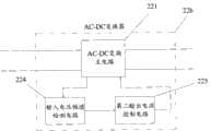
图9示出了本发明提供的LED的集中控制调光系统的另一个实施例中的AC-DC变换器的示意图,该AC-DC变换器包括AC-DC变换主电路221、并且同时包括输入电压频率检测电路222和输入电压幅值检测电路224,还包括与其对应的第一输出电流控制电路223和第二输出电流控制电路225。Fig. 9 shows the schematic diagram of the AC-DC converter in another embodiment of the centralized control and dimming system of LED provided by the present invention, the AC-DC converter includes the AC-DC conversionmain circuit 221, and at the same time includes the input The voltagefrequency detection circuit 222 and the input voltageamplitude detection circuit 224 also include a first outputcurrent control circuit 223 and a second outputcurrent control circuit 225 corresponding thereto.

其中,AC-DC变换主电路221将AC-AC变换器输出的方波交流电压信号进行变换,输出直流驱动电流,输入电压频率检测电路222检测AC-AC变换器输出的方波交流电压信号的频率,并将检测到的频率输出至第一输出电流控制电路223,第一输出电流控制电路223根据接收到的频率值,向AC-DC变换主电路221输出控制信号,以使AC-DC变换主电路221根据该控制信号确定输出的驱动电流。Among them, the AC-DC conversionmain circuit 221 converts the square-wave AC voltage signal output by the AC-AC converter to output a DC drive current, and the input voltagefrequency detection circuit 222 detects the square-wave AC voltage signal output by the AC-AC converter. frequency, and output the detected frequency to the first outputcurrent control circuit 223, and the first outputcurrent control circuit 223 outputs a control signal to the AC-DC conversionmain circuit 221 according to the received frequency value, so that the AC-DC conversion Themain circuit 221 determines the output driving current according to the control signal.

输入电压幅值检测电路224检测AC-AC变换器输出的交流电压信号的幅值,将检测到的幅值输出至第二输出电流控制电路225,第二输出电流控制电路225根据接收到的幅值,向AC-DC变换主电路221输出控制器信号,以使AC-DC变换主电路221根据控制信号确定输出的驱动电流。The input voltageamplitude detection circuit 224 detects the amplitude of the AC voltage signal output by the AC-AC converter, and outputs the detected amplitude to the second outputcurrent control circuit 225, and the second outputcurrent control circuit 225 value, and output a controller signal to the AC-DC conversionmain circuit 221, so that the AC-DC conversionmain circuit 221 determines the output driving current according to the control signal.

以上所述仅是本发明的优选实施方式,应当指出,对于本技术领域的普通技术人员来说,在不脱离本发明原理的前提下,还可以做出若干改进和润饰,这些改进和润饰也应视为本发明的保护范围。The above is only a preferred embodiment of the present invention, it should be pointed out that, for those of ordinary skill in the art, without departing from the principle of the present invention, some improvements and modifications can also be made, and these improvements and modifications can also be made. It should be regarded as the protection scope of the present invention.

Claims (17)

Translated fromChinese
1.一种LED的集中控制调光系统,其特征在于,包括:一AC-AC变换器,以及在AC-AC变换器与LED之间设置的AC-DC变换器;1. a centralized control dimming system of LED, is characterized in that, comprises: an AC-AC converter, and the AC-DC converter that is arranged between AC-AC converter and LED;其中,所述AC-AC变换器的两个输入端连接交流电源,两个输出端分别与每路LED对应的AC-DC变换器的输入端连接,每个AC-DC变换器的输出端与对应的一路LED连接;Wherein, the two input terminals of the AC-AC converter are connected to the AC power supply, and the two output terminals are respectively connected to the input terminals of the AC-DC converter corresponding to each LED, and the output terminals of each AC-DC converter are connected to the AC power supply. Corresponding one LED connection;所述AC-DC变换器根据所述AC-AC变换器输出的交流电压信号的频率或幅值设置输出至对应至少一路的LED的驱动电流;The AC-DC converter sets the drive current output to at least one LED corresponding to the frequency or amplitude of the AC voltage signal output by the AC-AC converter;所述AC-AC变换器输出可变频率或幅值的交流电压信号;所述AC-AC变换器包括:驱动控制电路、第一开关管Q1和第二开关管Q2、第一二极管D1和第二二极管D2、第一电容C1和第二电容C2;The AC-AC converter outputs an AC voltage signal with variable frequency or amplitude; the AC-AC converter includes: a drive control circuit, a first switching tube Q1 and a second switching tube Q2, and a first diode D1 And the second diode D2, the first capacitor C1 and the second capacitor C2;其中,所述第一二极管D1的阳极和第二二极管D2的阴极连接交流电源的第一端,所述第一二极管D1的阴极连接所述第一电容C1的正端和所述第一开关管Q1的第一端,所述第二二极管D2的阳极连接所述第二电容C2的负端和第二开关管Q2的第二端,所述第一电容C1的负端和所述第二电容C2的正端相连,并连接交流电源的第二端和控制器输出电压的第二端;所述第一开关管Q1的第二端和所述第二开关管Q2的第一端相连,并连接控制器输出电压的第一端;所述驱动控制电路的两个信号输出端分别连接第一开关管Q1的第三端和第二开关管Q2的第三端。Wherein, the anode of the first diode D1 and the cathode of the second diode D2 are connected to the first terminal of the AC power supply, and the cathode of the first diode D1 is connected to the positive terminal of the first capacitor C1 and The first terminal of the first switching tube Q1, the anode of the second diode D2 are connected to the negative terminal of the second capacitor C2 and the second terminal of the second switching tube Q2, and the first terminal of the first capacitor C1 The negative terminal is connected to the positive terminal of the second capacitor C2, and is connected to the second terminal of the AC power supply and the second terminal of the output voltage of the controller; the second terminal of the first switching tube Q1 is connected to the second terminal of the second switching tube The first end of Q2 is connected to the first end of the output voltage of the controller; the two signal output ends of the drive control circuit are respectively connected to the third end of the first switching tube Q1 and the third end of the second switching tube Q2 .2.根据权利要求1所述的LED的集中控制调光系统,其特征在于,所述AC-DC变换器包括:2. The centralized control dimming system of LED according to claim 1, wherein the AC-DC converter comprises:AC-DC变换主电路,用于将AC-AC变换器输出的交流电压信号进行变换,输出直流驱动电流;The AC-DC conversion main circuit is used to convert the AC voltage signal output by the AC-AC converter and output the DC drive current;输入电压频率检测电路,用于检测所述AC-AC变换器输出的交流电压信号的频率,将检测的频率输出至第一输出电流控制电路;an input voltage frequency detection circuit, configured to detect the frequency of the AC voltage signal output by the AC-AC converter, and output the detected frequency to the first output current control circuit;第一输出电流控制电路,用于根据接收到的频率值,向所述AC-DC变换主电路输出控制信号使其根据所述控制信号确定输出的驱动电流。The first output current control circuit is configured to output a control signal to the AC-DC conversion main circuit according to the received frequency value so that the output driving current can be determined according to the control signal.3.根据权利要求1所述的LED的集中控制调光系统,其特征在于,所述AC-DC变换器包括:3. The centralized control dimming system of LED according to claim 1, wherein the AC-DC converter comprises:AC-DC变换主电路,用于将从AC-AC变换器输出的交流电压信号进行变换,输出直流驱动电流;The AC-DC conversion main circuit is used to convert the AC voltage signal output from the AC-AC converter to output a DC drive current;输入电压幅值检测电路,用于检测所述AC-AC变换器输出的交流电压信号的幅值,将检测的幅值输出至第二输出电流控制电路;The input voltage amplitude detection circuit is used to detect the amplitude of the AC voltage signal output by the AC-AC converter, and output the detected amplitude to the second output current control circuit;第二输出电流控制电路,用于根据接收到的幅值,向所述AC-DC变换主电路输出控制信号使其根据控制信号确定输出的驱动电流。The second output current control circuit is configured to output a control signal to the AC-DC conversion main circuit so as to determine the output driving current according to the control signal according to the received amplitude.4.根据权利要求1所述的LED的集中控制调光系统,其特征在于,所述AC-DC变换器为至少一路输出的变换器。4. The LED centralized control and dimming system according to claim 1, wherein the AC-DC converter is a converter with at least one output.5.根据权利要求1所述的LED的集中控制调光系统,其特征在于,所述LED由一个或多个LED灯组成。5. The LED centralized control dimming system according to claim 1, characterized in that, the LED is composed of one or more LED lamps.6.一种LED的集中控制调光系统,其特征在于,包括:一AC-AC变换器,以及在AC-AC变换器与LED之间设置的AC-DC变换器;6. A centralized control dimming system for LEDs, comprising: an AC-AC converter, and an AC-DC converter arranged between the AC-AC converter and the LED;其中,所述AC-AC变换器的两个输入端连接交流电源,两个输出端分别与每路LED对应的AC-DC变换器的输入端连接,每个AC-DC变换器的输出端与对应的一路LED连接;Wherein, the two input terminals of the AC-AC converter are connected to the AC power supply, and the two output terminals are respectively connected to the input terminals of the AC-DC converter corresponding to each LED, and the output terminals of each AC-DC converter are connected to the AC power supply. Corresponding one LED connection;所述AC-DC变换器根据所述AC-AC变换器输出的交流电压信号的频率或幅值设置输出至对应至少一路的LED的驱动电流;The AC-DC converter sets the drive current output to at least one LED corresponding to the frequency or amplitude of the AC voltage signal output by the AC-AC converter;所述AC-AC变换器输出可变频率或幅值的交流电压信号;The AC-AC converter outputs an alternating voltage signal of variable frequency or amplitude;所述AC-AC变换器包括:电感L、整流桥BD、第三开关管Q3、驱动控制电路、第一开关管Q1和第二开关管Q2、第一二极管D1和第二二极管D2、第一电容C1和第二电容C2;所述电感L的第一端连接交流电源的第一端,所述电感L的第二端连接第一二极管D1的阳极和第二二极管D2的阴极,所述第一二极管D1的阴极连接第一电容C1的正端和第一开关管Q1的第一端,所述第二二极管D2的阳极连接所述第二电容C2的负端和第二开关管Q2的第二端,所述第一电容C1的负端和第二电容C2的正端相连,并连接交流电源的第二端和控制器输出电压的第二端;所述第一开关管的第二端和第二开关管的第一端相连,并连接控制器输出电压的第一端;所述驱动控制电路的两个信号输出端分别连接第一开关管Q1的第三端和第二开关管Q2的第三端;The AC-AC converter includes: an inductor L, a rectifier bridge BD, a third switch tube Q3, a drive control circuit, a first switch tube Q1 and a second switch tube Q2, a first diode D1 and a second diode D2, the first capacitor C1 and the second capacitor C2; the first end of the inductor L is connected to the first end of the AC power supply, and the second end of the inductor L is connected to the anode of the first diode D1 and the second diode The cathode of the tube D2, the cathode of the first diode D1 is connected to the positive end of the first capacitor C1 and the first end of the first switching tube Q1, and the anode of the second diode D2 is connected to the second capacitor The negative terminal of C2 is connected to the second terminal of the second switching tube Q2, the negative terminal of the first capacitor C1 is connected to the positive terminal of the second capacitor C2, and the second terminal of the AC power supply is connected to the second terminal of the output voltage of the controller. end; the second end of the first switch tube is connected to the first end of the second switch tube, and connected to the first end of the controller output voltage; the two signal output ends of the drive control circuit are respectively connected to the first switch The third end of the tube Q1 and the third end of the second switching tube Q2;所述整流桥BD的两个交流输入端分别连接电感L的第二端和交流电源的第二端;所述整流桥BD的两个输出端分别连接第三开关管Q3的两端。The two AC input terminals of the rectifier bridge BD are respectively connected to the second terminal of the inductor L and the second terminal of the AC power supply; the two output terminals of the rectifier bridge BD are respectively connected to both ends of the third switching tube Q3.7.根据权利要求6所述的LED的集中控制调光系统,其特征在于,所述AC-DC变换器包括:7. The centralized control dimming system of LED according to claim 6, wherein the AC-DC converter comprises:AC-DC变换主电路,用于将AC-AC变换器输出的交流电压信号进行变换,输出直流驱动电流;The AC-DC conversion main circuit is used to convert the AC voltage signal output by the AC-AC converter and output the DC drive current;输入电压频率检测电路,用于检测所述AC-AC变换器输出的交流电压信号的频率,将检测的频率输出至第一输出电流控制电路;an input voltage frequency detection circuit, configured to detect the frequency of the AC voltage signal output by the AC-AC converter, and output the detected frequency to the first output current control circuit;第一输出电流控制电路,用于根据接收到的频率值,向所述AC-DC变换主电路输出控制信号使其根据所述控制信号确定输出的驱动电流。The first output current control circuit is configured to output a control signal to the AC-DC conversion main circuit according to the received frequency value so that the output driving current can be determined according to the control signal.8.根据权利要求6所述的LED的集中控制调光系统,其特征在于,所述AC-DC变换器包括:8. The centralized control dimming system of LED according to claim 6, wherein the AC-DC converter comprises:AC-DC变换主电路,用于将从AC-AC变换器输出的交流电压信号进行变换,输出直流驱动电流;The AC-DC conversion main circuit is used to convert the AC voltage signal output from the AC-AC converter to output a DC drive current;输入电压幅值检测电路,用于检测所述AC-AC变换器输出的交流电压信号的幅值,将检测的幅值输出至第二输出电流控制电路;The input voltage amplitude detection circuit is used to detect the amplitude of the AC voltage signal output by the AC-AC converter, and output the detected amplitude to the second output current control circuit;第二输出电流控制电路,用于根据接收到的幅值,向所述AC-DC变换主电路输出控制信号使其根据控制信号确定输出的驱动电流。The second output current control circuit is configured to output a control signal to the AC-DC conversion main circuit so as to determine the output driving current according to the control signal according to the received amplitude.9.根据权利要求6所述的LED的集中控制调光系统,其特征在于,所述AC-DC变换器包括:9. The centralized control and dimming system of LED according to claim 6, wherein the AC-DC converter comprises:AC-DC变换主电路,用于将AC-AC变换器输出的交流电压信号进行变换,输出直流驱动电流;The AC-DC conversion main circuit is used to convert the AC voltage signal output by the AC-AC converter and output the DC drive current;输入电压频率检测电路,用于检测所述AC-AC变换器输出的交流电压信号的频率,将检测的频率输出至第一输出电流控制电路;an input voltage frequency detection circuit, configured to detect the frequency of the AC voltage signal output by the AC-AC converter, and output the detected frequency to the first output current control circuit;第一输出电流控制电路,用于根据接收到的频率值,向所述AC-DC变换主电路输出控制信号使其根据所述控制信号确定输出的驱动电流;The first output current control circuit is used to output a control signal to the AC-DC conversion main circuit according to the received frequency value so as to determine the output driving current according to the control signal;AC-DC变换主电路,用于将从AC-AC变换器输出的交流电压信号进行变换,输出直流驱动电流;The AC-DC conversion main circuit is used to convert the AC voltage signal output from the AC-AC converter to output a DC drive current;输入电压幅值检测电路,用于检测所述AC-AC变换器输出的交流电压信号的幅值,将检测的幅值输出至第二输出电流控制电路;The input voltage amplitude detection circuit is used to detect the amplitude of the AC voltage signal output by the AC-AC converter, and output the detected amplitude to the second output current control circuit;第二输出电流控制电路,用于根据接收到的幅值,向所述AC-DC变换主电路输出控制信号使其根据控制信号确定输出的驱动电流。The second output current control circuit is configured to output a control signal to the AC-DC conversion main circuit so as to determine the output driving current according to the control signal according to the received amplitude.10.根据权利要求6所述的LED的集中控制调光系统,其特征在于,所述AC-DC变换器为至少一路输出的变换器。10. The LED centralized control and dimming system according to claim 6, wherein the AC-DC converter is a converter with at least one output.11.根据权利要求6所述的LED的集中控制调光系统,其特征在于,所述LED由一个或多个LED灯组成。11. The LED centralized control dimming system according to claim 6, characterized in that, the LED is composed of one or more LED lamps.12.一种LED的集中控制调光系统,其特征在于,包括:一AC-AC变换器,以及在AC-AC变换器与LED之间设置的AC-DC变换器;12. A centralized control dimming system for LEDs, comprising: an AC-AC converter, and an AC-DC converter arranged between the AC-AC converter and the LED;其中,所述AC-AC变换器的两个输入端连接交流电源,两个输出端分别与每路LED对应的AC-DC变换器的输入端连接,每个AC-DC变换器的输出端与对应的一路LED连接;Wherein, the two input terminals of the AC-AC converter are connected to the AC power supply, and the two output terminals are respectively connected to the input terminals of the AC-DC converter corresponding to each LED, and the output terminals of each AC-DC converter are connected to the AC power supply. Corresponding one LED connection;所述AC-DC变换器根据所述AC-AC变换器输出的交流电压信号的频率或幅值设置输出至对应至少一路的LED的驱动电流;The AC-DC converter sets the drive current output to at least one LED corresponding to the frequency or amplitude of the AC voltage signal output by the AC-AC converter;所述AC-AC变换器输出可变频率或幅值的交流电压信号;The AC-AC converter outputs an alternating voltage signal of variable frequency or amplitude;所述AC-AC变换器包括:第三二极管D3和第四二极管D4、第一电感L1和第二电感L2、第一二极管D1和第二二极管D2、第一电容C1和第二电容C2,第一开关管Q1、第二开关管Q2、第四开关管Q4和第五开关管Q5、以及驱动控制电路;The AC-AC converter includes: a third diode D3 and a fourth diode D4, a first inductor L1 and a second inductor L2, a first diode D1 and a second diode D2, a first capacitor C1 and the second capacitor C2, the first switching tube Q1, the second switching tube Q2, the fourth switching tube Q4 and the fifth switching tube Q5, and the drive control circuit;其中,所述第三二极管D3的阳极和第四二极管D4的阴极与交流电源的第一端连接,所述第一电感L1的第一端与第三二极管D3的阴极连接,第二端与第四开关管Q4的第一端和第一二极管D1的阳极连接,所述第二电感L2的第一端连接第四二极管D4的阳极,第二端连接第四开关管Q4的第二端和第二二极管D2的阴极,第四开关管Q4的第二端与第五开关管Q5的第一端连接,并连接所述交流电源的第二端,所述第一二极管D1的阴极连接第一电容C1的正端和第一开关管Q1的第一端,所述第二二极管D2的阳极连接第二电容C2的负端和第二开关管Q2的第二端,第一电容C1的负端连接第二电容C2的正端,并连接所述交流电源的第二端和控制器输出电压的第二端,所述第一开关管Q1的第二端和第二开关管Q2的第一端连接,并连接控制器输出电压的第一端,所述驱动控制电路的两个信号输出端分别连接第一开关管Q1的第三端和第二开关管Q2的第三端。Wherein, the anode of the third diode D3 and the cathode of the fourth diode D4 are connected to the first end of the AC power supply, and the first end of the first inductor L1 is connected to the cathode of the third diode D3 , the second terminal is connected to the first terminal of the fourth switch tube Q4 and the anode of the first diode D1, the first terminal of the second inductor L2 is connected to the anode of the fourth diode D4, and the second terminal is connected to the anode of the first diode D4. The second end of the four switching tube Q4 is connected to the cathode of the second diode D2, the second end of the fourth switching tube Q4 is connected to the first end of the fifth switching tube Q5, and connected to the second end of the AC power supply, The cathode of the first diode D1 is connected to the positive terminal of the first capacitor C1 and the first terminal of the first switching tube Q1, and the anode of the second diode D2 is connected to the negative terminal of the second capacitor C2 and the second The second end of the switch tube Q2, the negative end of the first capacitor C1 is connected to the positive end of the second capacitor C2, and is connected to the second end of the AC power supply and the second end of the controller output voltage, the first switch tube The second terminal of Q1 is connected to the first terminal of the second switching tube Q2, and is connected to the first terminal of the output voltage of the controller, and the two signal output terminals of the drive control circuit are respectively connected to the third terminal of the first switching tube Q1 and the third terminal of the second switch tube Q2.13.根据权利要求12所述的LED的集中控制调光系统,其特征在于,所述AC-DC变换器包括:13. The centralized control dimming system of LED according to claim 12, wherein the AC-DC converter comprises:AC-DC变换主电路,用于将AC-AC变换器输出的交流电压信号进行变换,输出直流驱动电流;The AC-DC conversion main circuit is used to convert the AC voltage signal output by the AC-AC converter and output the DC drive current;输入电压频率检测电路,用于检测所述AC-AC变换器输出的交流电压信号的频率,将检测的频率输出至第一输出电流控制电路;an input voltage frequency detection circuit, configured to detect the frequency of the AC voltage signal output by the AC-AC converter, and output the detected frequency to the first output current control circuit;第一输出电流控制电路,用于根据接收到的频率值,向所述AC-DC变换主电路输出控制信号使其根据所述控制信号确定输出的驱动电流。The first output current control circuit is configured to output a control signal to the AC-DC conversion main circuit according to the received frequency value so that the output driving current can be determined according to the control signal.14.根据权利要求12所述的LED的集中控制调光系统,其特征在于,所述AC-DC变换器包括:14. The LED centralized control and dimming system according to claim 12, wherein the AC-DC converter comprises:AC-DC变换主电路,用于将从AC-AC变换器输出的交流电压信号进行变换,输出直流驱动电流;The AC-DC conversion main circuit is used to convert the AC voltage signal output from the AC-AC converter to output a DC drive current;输入电压幅值检测电路,用于检测所述AC-AC变换器输出的交流电压信号的幅值,将检测的幅值输出至第二输出电流控制电路;The input voltage amplitude detection circuit is used to detect the amplitude of the AC voltage signal output by the AC-AC converter, and output the detected amplitude to the second output current control circuit;第二输出电流控制电路,用于根据接收到的幅值,向所述AC-DC变换主电路输出控制信号使其根据控制信号确定输出的驱动电流。The second output current control circuit is configured to output a control signal to the AC-DC conversion main circuit so as to determine the output driving current according to the control signal according to the received amplitude.15.根据权利要求12所述的LED的集中控制调光系统,其特征在于,所述AC-DC变换器包括:15. The centralized control dimming system of LED according to claim 12, characterized in that, the AC-DC converter comprises:AC-DC变换主电路,用于将AC-AC变换器输出的交流电压信号进行变换,输出直流驱动电流;The AC-DC conversion main circuit is used to convert the AC voltage signal output by the AC-AC converter and output the DC drive current;输入电压频率检测电路,用于检测所述AC-AC变换器输出的交流电压信号的频率,将检测的频率输出至第一输出电流控制电路;an input voltage frequency detection circuit, configured to detect the frequency of the AC voltage signal output by the AC-AC converter, and output the detected frequency to the first output current control circuit;第一输出电流控制电路,用于根据接收到的频率值,向所述AC-DC变换主电路输出控制信号使其根据所述控制信号确定输出的驱动电流;The first output current control circuit is used to output a control signal to the AC-DC conversion main circuit according to the received frequency value so as to determine the output driving current according to the control signal;AC-DC变换主电路,用于将从AC-AC变换器输出的交流电压信号进行变换,输出直流驱动电流;The AC-DC conversion main circuit is used to convert the AC voltage signal output from the AC-AC converter to output a DC drive current;输入电压幅值检测电路,用于检测所述AC-AC变换器输出的交流电压信号的幅值,将检测的幅值输出至第二输出电流控制电路;The input voltage amplitude detection circuit is used to detect the amplitude of the AC voltage signal output by the AC-AC converter, and output the detected amplitude to the second output current control circuit;第二输出电流控制电路,用于根据接收到的幅值,向所述AC-DC变换主电路输出控制信号使其根据控制信号确定输出的驱动电流。The second output current control circuit is configured to output a control signal to the AC-DC conversion main circuit so as to determine the output driving current according to the control signal according to the received amplitude.16.根据权利要求12所述的LED的集中控制调光系统,其特征在于,所述AC-DC变换器为至少一路输出的变换器。16. The LED centralized control dimming system according to claim 12, wherein the AC-DC converter is a converter with at least one output.17.根据权利要求12所述的LED的集中控制调光系统,其特征在于,所述LED由一个或多个LED灯组成。17. The LED centralized control dimming system according to claim 12, characterized in that, the LED is composed of one or more LED lamps.
CN2010101922022A2010-06-022010-06-02Centralized control dimming system of LEDExpired - Fee RelatedCN101861024B (en)

Priority Applications (1)

Application NumberPriority DateFiling DateTitle
CN2010101922022ACN101861024B (en)2010-06-022010-06-02Centralized control dimming system of LED

Applications Claiming Priority (1)

Application NumberPriority DateFiling DateTitle
CN2010101922022ACN101861024B (en)2010-06-022010-06-02Centralized control dimming system of LED

Publications (2)

Publication NumberPublication Date
CN101861024A CN101861024A (en)2010-10-13
CN101861024Btrue CN101861024B (en)2013-12-11

Family

ID=42946583

Family Applications (1)

Application NumberTitlePriority DateFiling Date
CN2010101922022AExpired - Fee RelatedCN101861024B (en)2010-06-022010-06-02Centralized control dimming system of LED

Country Status (1)

CountryLink
CN (1)CN101861024B (en)

Families Citing this family (3)

* Cited by examiner, † Cited by third party
Publication numberPriority datePublication dateAssigneeTitle
CN102548101B (en)*2010-12-272014-05-28英飞特电子(杭州)股份有限公司LED dimming system
CN102548109B (en)*2010-12-302014-05-28英飞特电子(杭州)股份有限公司Load driving device and system
CN102280089A (en)*2011-08-182011-12-14深圳市华星光电技术有限公司Light emitting diode (LED) backlight driving method and circuit and liquid crystal display device

Citations (3)

* Cited by examiner, † Cited by third party
Publication numberPriority datePublication dateAssigneeTitle
CN101605413A (en)*2009-07-062009-12-16英飞特电子(杭州)有限公司Be applicable to the led drive circuit of controllable silicon light modulation
CN201438773U (en)*2009-07-312010-04-14深圳市通普科技有限公司LED dimming device
CN201830495U (en)*2010-06-022011-05-11艾迪光电(杭州)有限公司Light dimming system with centralized control for light emitting diodes (LEDs)

Family Cites Families (2)

* Cited by examiner, † Cited by third party
Publication numberPriority datePublication dateAssigneeTitle
JP2007080771A (en)*2005-09-162007-03-29Nec Lighting Ltd Low voltage power supply circuit for lighting, lighting device, and low voltage power supply output method for lighting
CN101630105B (en)*2008-07-152011-10-12比亚迪股份有限公司Liquid-crystal zoom lens and electronic device

Patent Citations (3)

* Cited by examiner, † Cited by third party
Publication numberPriority datePublication dateAssigneeTitle
CN101605413A (en)*2009-07-062009-12-16英飞特电子(杭州)有限公司Be applicable to the led drive circuit of controllable silicon light modulation
CN201438773U (en)*2009-07-312010-04-14深圳市通普科技有限公司LED dimming device
CN201830495U (en)*2010-06-022011-05-11艾迪光电(杭州)有限公司Light dimming system with centralized control for light emitting diodes (LEDs)

Also Published As

Publication numberPublication date
CN101861024A (en)2010-10-13

Similar Documents

PublicationPublication DateTitle
CN102612206B (en)LED driving apparatus and LED lighting apparatus
CN102300355B (en)Light emitting diode (LED) dimming system
CN102752940B (en)High-efficiency LED (light-emitting diode) drive circuit and drive method thereof
CN103139992B (en)With the LED dimming drive system of controllable silicon bypass light adjusting circuit
TWI586216B (en)Improvements relating to lighting systems
CN102510610A (en)Single-stage AC-DC (alternating current-direct current) high-power LED (light-emitting diode) lighting drive circuit
WO2017124748A1 (en)Switch power supply having active power factor correction
CN101917793B (en)Wireless driving system of light-emitting diode
CN103891405B (en) Drivers for connecting LEDs to electronic ballasts
CN201813599U (en)LED (Light-Emitting Diode) dimmer power
CN102458014A (en)Light source control method, device and system
CN102014557A (en)LED dimming power supply
CN201690655U (en)Flyback road lamp illuminating LED constant-current driving power supply with intelligent dimming function
CN203193980U (en)Drive circuit for multi-channel dimmable LED (light-emitting diode) lamp tube
TWI538564B (en) Integrated light-emitting diode driving circuit and operating method thereof
CN101861024B (en)Centralized control dimming system of LED
US9049763B1 (en)LED luminaire driving circuit with high power factor
CN201528447U (en)LED driving power supply circuit
CN203181303U (en)Light modulator used for voltage drop dimming light fixture
CN101938869B (en)Direct current (DC) control device in alternating current (AC) system
CN201690650U (en)Wireless control system used for LED dimming
CN201830495U (en)Light dimming system with centralized control for light emitting diodes (LEDs)
CN111565489A (en)LED drive circuit with independently controllable illumination and visible light communication
CN201967185U (en)Light source control device and system
CN202396071U (en) A HID electronic ballast based on wireless control of the Internet of Things

Legal Events

DateCodeTitleDescription
C06Publication
PB01Publication
C10Entry into substantive examination
SE01Entry into force of request for substantive examination
C53Correction of patent of invention or patent application
CB02Change of applicant information

Address after:Hangzhou City, Zhejiang province 310053 Binjiang District Dongxin Road No. 66 East communication B block 309

Applicant after:LED ONE (HANGZHOU) Co.,Ltd.

Address before:Hangzhou City, Zhejiang province 310053 Binjiang District Dongxin Road No. 66 East communication B block 309

Applicant before:LED ONE (HANGZHOU) Co.,Ltd.

CORChange of bibliographic data

Free format text:CORRECT: APPLICANT; FROM: LEDONE HANGZHOU CO., LTD. TO: LED ONE (HANGZHOU) CO., LTD.

ASSSuccession or assignment of patent right

Owner name:ZHEJIANG THINKLUX LIGHTING TECHNOLOGY CO., LTD.

Free format text:FORMER OWNER: INVENTRONICS (HANGZHOU), INC.

Effective date:20130328

C41Transfer of patent application or patent right or utility model
CORChange of bibliographic data

Free format text:CORRECT: ADDRESS; FROM: 310053 HANGZHOU, ZHEJIANG PROVINCE TO: 315002 HANGZHOU, ZHEJIANG PROVINCE

TA01Transfer of patent application right

Effective date of registration:20130328

Address after:Hangzhou City, Zhejiang province Binjiang District 315002 shore road 95 2 Building 3 layer

Applicant after:Zhejiang Silang Lighting Co.,Ltd.

Address before:Hangzhou City, Zhejiang province 310053 Binjiang District Dongxin Road No. 66 East communication B block 309

Applicant before:LED ONE (HANGZHOU) Co.,Ltd.

C14Grant of patent or utility model
GR01Patent grant
C41Transfer of patent application or patent right or utility model
TR01Transfer of patent right

Effective date of registration:20151112

Address after:528226, Guangdong Province, Nanhai District, Foshan province Luo village, Guangdong new light industry base A8 Building 5 floor

Patentee after:GUANGDONG SOLID STATE LIGHTING INDUSTRY INNOVATION CENTER

Address before:Hangzhou City, Zhejiang province Binjiang District 315002 shore road 95 2 Building 3 layer

Patentee before:Zhejiang Silang Lighting Co.,Ltd.

TR01Transfer of patent right

Effective date of registration:20191101

Address after:516001 room 2306, 23 / F, innovation building, No.106, Dongxin Avenue, Dongjiang Industrial Park, Zhongkai high tech Zone, Huizhou City, Guangdong Province

Patentee after:Huizhou Qianfeng Guangcai Technology Co.,Ltd.

Address before:528226, Guangdong Province, Nanhai District, Foshan province Luo village, Guangdong new light industry base A8 Building 5 floor

Patentee before:GUANGDONG SOLID STATE LIGHTING INDUSTRY INNOVATION CENTER

PP01Preservation of patent right

Effective date of registration:20220401

Granted publication date:20131211

PD01Discharge of preservation of patent

Date of cancellation:20250401

Granted publication date:20131211

CF01Termination of patent right due to non-payment of annual fee

Granted publication date:20131211


[8]ページ先頭

©2009-2025 Movatter.jp