CN101859738B - Large-area liquid-cooled heat dissipation device - Google Patents
Large-area liquid-cooled heat dissipation deviceDownload PDFInfo
- Publication number
- CN101859738B CN101859738BCN2009101283670ACN200910128367ACN101859738BCN 101859738 BCN101859738 BCN 101859738BCN 2009101283670 ACN2009101283670 ACN 2009101283670ACN 200910128367 ACN200910128367 ACN 200910128367ACN 101859738 BCN101859738 BCN 101859738B
- Authority
- CN
- China
- Prior art keywords
- heat
- absorbing
- liquid
- pipe
- pipes
- Prior art date
- Legal status (The legal status is an assumption and is not a legal conclusion. Google has not performed a legal analysis and makes no representation as to the accuracy of the status listed.)
- Expired - Fee Related
Links
- 230000017525heat dissipationEffects0.000titleclaimsabstractdescription38
- 239000000110cooling liquidSubstances0.000claimsabstractdescription49
- 239000007788liquidSubstances0.000claimsabstractdescription46
- 238000002347injectionMethods0.000claimsabstractdescription44
- 239000007924injectionSubstances0.000claimsabstractdescription44
- 238000009792diffusion processMethods0.000claimsabstractdescription40
- 238000010521absorption reactionMethods0.000claimsabstractdescription38
- XLYOFNOQVPJJNP-UHFFFAOYSA-NwaterSubstancesOXLYOFNOQVPJJNP-UHFFFAOYSA-N0.000claimsdescription38
- 238000003780insertionMethods0.000claimsdescription8
- 230000037431insertionEffects0.000claimsdescription8
- 239000002826coolantSubstances0.000claimsdescription6
- 230000000694effectsEffects0.000abstractdescription11
- 238000010438heat treatmentMethods0.000abstract4
- 238000001816coolingMethods0.000description4
- 238000013461designMethods0.000description4
- 239000002918waste heatSubstances0.000description3
- 239000012530fluidSubstances0.000description2
- 238000012546transferMethods0.000description2
- 239000006096absorbing agentSubstances0.000description1
- 238000005452bendingMethods0.000description1
- 238000009434installationMethods0.000description1
- 238000000034methodMethods0.000description1
- 238000012986modificationMethods0.000description1
- 230000004048modificationEffects0.000description1
- 239000004065semiconductorSubstances0.000description1
Images


Landscapes
- Cooling Or The Like Of Electrical Apparatus (AREA)
Abstract
Description
Translated fromChinese技术领域technical field
本发明涉及一种大面积液冷式散热装置,特别是涉及一种具针对不同位置的散热需求而提供不同散热效果的大面积液冷式散热装置。The invention relates to a large-area liquid-cooled heat dissipation device, in particular to a large-area liquid-cooled heat dissipation device that provides different heat dissipation effects according to heat dissipation requirements at different positions.
背景技术Background technique
目前一般计算机,例如个人计算机、伺服器等,其所要处理的运算工作日益繁杂,故芯片及半导体开关等多个电子元件工作时所产生的废热温度极高,为使该些电子元件降温,通常于电子元件上加装一风扇或液冷散热装置,以对电子元件进行散热。At present, general computers, such as personal computers, servers, etc., have to deal with increasingly complex computing tasks, so the waste heat generated by multiple electronic components such as chips and semiconductor switches is extremely high. In order to cool these electronic components, usually Install a fan or a liquid-cooled heat sink on the electronic components to dissipate heat from the electronic components.
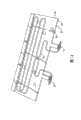
为有效地令多个发热电子元件散热,请参阅图11所示,一种现有应用于伺服器的大面积液冷式散热装置包括一热扩散板60及一具有单一管径的吸热管70,其中该热扩散板60具有一供与伺服器的电子元件80直接接触的吸热面61及一散热面62,而该吸热管70蜿蜒地设于该热扩散板60的散热面62上,以平均分布于该热扩散板60的散热面62上而构成热接触,又该吸热管70具有一入口端71及一出口端72,该入口端71供将冷却液注入该吸热管70中,借由冷却液流经吸热管70时,一并对热扩散板60自电子元件80吸取的废热进行热交换,以将堆积于热扩散板60上的废热带走,进而达到对电子元件80散热降温的效果。In order to effectively dissipate heat from multiple heat-generating electronic components, please refer to FIG. 11 . A conventional large-area liquid-cooled cooling device for servers includes a
但上述大面积液冷式散热装置具有以下缺点:However, the above-mentioned large-area liquid-cooled heat dissipation device has the following disadvantages:
1.为令该单一吸热管70可平均分布于该热扩散板60上,以对该热扩散板60的散热面62上各处吸热,势必要设计令该单一吸热管70具有多处弯折,才能使该单一吸热管70借由蜿蜒地来回延伸,而平均地分布设置于该热扩散板60上,然而过多的弯折,将造成冷却液于吸热管70中传递的阻碍,导致该大面积液冷式散热装置必须使用较强力的泵方可令冷却液顺畅地于该吸热管70中流动。1. In order to make the single heat-absorbing
2.为令该单一吸热管70可平均分布于该大面积液冷式散热装置的热扩散板60上,该单一吸热管70的长度必须够长,方可将该单一吸热管70以多处弯折的设计,蜿蜒地分布设置于该热扩散板60上,但蜿蜒设置必然造成吸热管70的长度较长,如此将造成流经入口端71及出口端72的冷却液之间具有过大的温差,导致该吸热管70上靠近该单一吸热管70出口端72处的热交换能力与靠近该单一吸热管70出口端72处的热交换能力有明显的差异,因此,伺服器主机板在设计时,也必须针对该大面积液冷式散热装置散热能力不均的缺点,而调整伺服器主机板上电子元件80的线路布局,例如发热温度较高的电子元件80必须设计在对应靠近吸热管70入口端71处,因而提高了线路布局的复杂度。2. In order to make the single heat-absorbing
发明内容Contents of the invention
本发明的目的在于提供一种大面积液冷式散热装置,其可针对不同位置的散热需求而提供不同散热效果,以解决现有大面积液冷式散热装置的散热效果不均的问题。The purpose of the present invention is to provide a large-area liquid-cooled heat dissipation device, which can provide different heat dissipation effects according to the heat dissipation requirements of different locations, so as to solve the problem of uneven heat dissipation effects of existing large-area liquid-cooled heat sinks.
为了实现上述目的,本发明提供了一种液冷式散热装置,包括:In order to achieve the above object, the present invention provides a liquid-cooled heat sink, comprising:
一热扩散板,具有一吸热面及一散热面,其中该吸热面供与多个发热源接触;A thermal diffusion plate has a heat-absorbing surface and a heat-dissipating surface, wherein the heat-absorbing surface is in contact with a plurality of heat sources;
一注液分布器,具有至少一入水口及多个送水口;A liquid injection distributor having at least one water inlet and multiple water delivery ports;
多个吸热管,分布设于该热扩散板的散热面上,且各吸热管具有一入口端及一出口端,其中该多个吸热管的入口端分别与该注液分布器的多个送水口连接,而与该注液分布器连通,又各吸热管内具有一冷却液通道,且该多个吸热管的冷却液通道的截面积均不相同,具有较大冷却液通道截面积的吸热管对应温度较高的发热源,其中,该多个吸热管呈环状回路,且具有不同的长度,较长吸热管的冷却液通道的截面积较大;一排液收集器,具有至少一出水口及多个进水口,其中该多个进水口分别与该多个吸热管的出口端连接,并通过该多个吸热管与该注液分布器连通。A plurality of heat-absorbing pipes are distributed on the heat dissipation surface of the heat diffusion plate, and each heat-absorbing pipe has an inlet end and an outlet end, wherein the inlet ends of the plurality of heat-absorbing pipes are respectively connected to the liquid injection distributor A plurality of water delivery ports are connected and communicated with the liquid injection distributor, and there is a cooling liquid channel in each heat absorbing tube, and the cross-sectional areas of the cooling liquid channels of the multiple heat absorbing tubes are all different, and there is a larger cooling liquid channel The heat-absorbing pipes with cross-sectional area correspond to the heat source with higher temperature, wherein, the multiple heat-absorbing pipes are in a circular loop and have different lengths, and the cooling liquid channel of the longer heat-absorbing pipe has a larger cross-sectional area; a row of The liquid collector has at least one water outlet and a plurality of water inlets, wherein the plurality of water inlets are respectively connected to the outlet ends of the plurality of heat-absorbing pipes, and communicate with the liquid injection distributor through the plurality of heat-absorbing pipes.
本发明还提出一种大面积液冷式散热装置,其包括:The present invention also proposes a large-area liquid-cooled heat sink, which includes:
一热扩散板,具有一吸热面及一散热面;该热扩散板包括一下盖板及一上盖板,其中:该下盖板的底面为该热扩散板的吸热面,而该下盖板的顶面上形成有一下注液分布器嵌槽、多个下吸热管嵌槽及一下排液收集器嵌槽;该上盖板以其底面盖设于该下盖板的顶面上,且该上盖板的顶面为该热扩散板的散热面,而该上盖板的底面形成有一上注液分布器嵌槽、多个上吸热管嵌槽及一上排液收集器嵌槽,其中该上注液分布器嵌槽、上吸热管嵌槽及上排液收集器嵌槽对应该下盖板的下注液分布器嵌槽、下吸热管嵌槽及下排液收集器嵌槽;A heat diffusion plate has a heat absorption surface and a heat dissipation surface; the heat diffusion plate includes a lower cover plate and an upper cover plate, wherein: the bottom surface of the lower cover plate is the heat absorption surface of the heat diffusion plate, and the lower cover plate The top surface of the cover plate is formed with a lower injection distributor slot, a plurality of lower heat absorption pipe slots and a lower drain collector slot; the upper cover plate is set on the top surface of the lower cover plate with its bottom surface and the top surface of the upper cover plate is the heat dissipation surface of the thermal diffusion plate, and the bottom surface of the upper cover plate is formed with an upper liquid injection distributor slot, a plurality of upper heat absorption pipe slots and an upper drain collection The slot of the upper injection distributor, the slot of the upper heat-absorbing pipe and the slot of the upper drain collector correspond to the slot of the lower injection distributor, the slot of the lower heat-absorbing tube and the slot of the lower cover plate. drain collector slot;
一注液分布器,由所述上、下注液分布器嵌槽构成,具有至少一入水口及多个送水口;多个吸热管,所述吸热管由所述上、下吸热管嵌槽构成,各吸热管具有一入口端及一出口端,其中入口端分别与该注液分布器的多个送水口连接,而与该注液分布器连通;各吸热管内具有一冷却液通道,且各吸热管的冷却液通道分属至少两种不同的截面积,各上、下吸热管嵌槽的深度决定吸热管的冷却液通道的截面积大小,其中,该多个吸热管呈环状回路,且具有不同的长度,较长吸热管的冷却液通道的截面积较大;一排液收集器,由所述上、下排液收集器嵌槽构成,该排液收集器具有至少一出水口及多个进水口,其中该多个进水口分别与该多个吸热管的出口端连接,并通过该多个吸热管与该注液分布器连通。A liquid injection distributor, which is composed of the upper and lower injection distributors, has at least one water inlet and a plurality of water delivery ports; a plurality of heat absorption pipes, the heat absorption pipes are formed by the upper and lower heat Each heat-absorbing tube has an inlet port and an outlet port, wherein the inlet ports are respectively connected to multiple water delivery ports of the liquid injection distributor, and communicated with the liquid injection distributor; each heat-absorbing tube has a Cooling liquid channels, and the cooling liquid channels of each heat-absorbing pipe belong to at least two different cross-sectional areas, and the depth of each upper and lower heat-absorbing pipe embedding groove determines the cross-sectional area of the cooling liquid channel of the heat-absorbing pipe, wherein, the A plurality of heat-absorbing pipes are annular loops with different lengths, and the cross-sectional area of the cooling liquid channel of the longer heat-absorbing pipes is larger; a drain collector is formed by the upper and lower drain collector grooves , the drain collector has at least one water outlet and a plurality of water inlets, wherein the plurality of water inlets are respectively connected to the outlet ends of the plurality of heat-absorbing pipes, and connected to the liquid injection distributor through the plurality of heat-absorbing pipes connected.
利用上述技术手段,由于本液冷式散热装置使用较多的吸热管,故各吸热管可设计以最少的弯管次数,分布设于该热扩散板上,借此减少冷却液于吸热管中传递时的阻碍;此外,再将具有较大截面积冷却液通道的吸热管与温度较高的发热源对应设置,可提高对温度较高发热源的吸热效果,故可由本散热装置配合线路布局,在设计上较有弹性,并可减少线路布局的负担。Utilizing the above-mentioned technical means, since the liquid-cooled heat dissipation device uses more heat-absorbing tubes, each heat-absorbing tube can be designed to be distributed on the thermal diffusion plate with the least number of pipe bends, thereby reducing the amount of cooling liquid on the heat-absorbing plate. In addition, the heat absorption pipe with a larger cross-sectional area of the cooling liquid channel is arranged correspondingly to the heat source with a higher temperature, which can improve the heat absorption effect on the heat source with a higher temperature, so the heat dissipation can be achieved by this The device is matched with the circuit layout, which is more flexible in design and can reduce the burden of circuit layout.
附图说明Description of drawings
图1为本发明第一实施例的外观图;Fig. 1 is the exterior view of the first embodiment of the present invention;
图2为本发明第一实施例的部分分解图;Figure 2 is a partial exploded view of the first embodiment of the present invention;
图3为本发明第一实施例的分解图;Figure 3 is an exploded view of the first embodiment of the present invention;
图4为本发明第一实施例的俯视图;Fig. 4 is the top view of the first embodiment of the present invention;
图5为本发明第二实施例的分解图;Figure 5 is an exploded view of the second embodiment of the present invention;
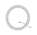
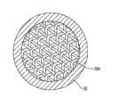
图6为本发明第三实施例的外观图;Fig. 6 is the exterior view of the third embodiment of the present invention;
图7为本发明第三实施例中最长吸热管的剖面图;Fig. 7 is a sectional view of the longest heat absorbing pipe in the third embodiment of the present invention;
图8为本发明第三实施例中次长吸热管的剖面图;Fig. 8 is a sectional view of the second long heat absorbing pipe in the third embodiment of the present invention;
图9为本发明第三实施例中次短吸热管的剖面图;Fig. 9 is a cross-sectional view of the second short heat absorbing pipe in the third embodiment of the present invention;
图10为本发明第三实施例中最短吸热管的剖面图;Fig. 10 is a sectional view of the shortest heat absorbing pipe in the third embodiment of the present invention;
图11为现有大面积液冷式散热装置的外观图。FIG. 11 is an appearance view of a conventional large-area liquid-cooled heat sink.
主要元件标号说明:Explanation of main component labels:
10热扩散板10 thermal diffusion plate
101 下盖板 101a 下注液分布器嵌槽101
101b 下吸热管嵌槽 101c 下排液收集器嵌槽101b Bottom heat-absorbing
102 上盖板 102a 上注液分布器嵌槽102
102b 上吸热管嵌槽 102c 上排液收集器嵌槽102b Insertion groove for upper
11 吸热面 12 散热面11 heat-absorbing
20 注液分布器 21 入水口20
22 送水口 30 吸热管22
301 平滑内壁 302 锯齿内壁301 smooth
303 一粗糙内壁 304 栅网303 a rough
31 入口端 32 出口端31
40 排液收集器 41 出水口40
42 进水口 50 发热源42 Water inlet 50 Heat source
60 热扩散板 61 吸热面60
62 散热面 70 吸热管62
71 入口端 72 出口端71
80 电子元件80 electronic components
具体实施方式Detailed ways
关于本发明的第一实施例,请参阅图1至图4所示,包括一热扩散板10、一注液分布器20、多个吸热管30及一排液收集器40。Regarding the first embodiment of the present invention, please refer to FIG. 1 to FIG. 4 , which includes a
上述热扩散板10具有一吸热面11及一散热面12,其中该吸热面11供与多个发热源50构成热接触,例如伺服器主机板上的电子元件;于本实施例中,该热扩散板10为一矩形片状板体。The above-mentioned
请进一步参阅图4所示,上述注液分布器20具有至少一入水口21及多个送水口22;于本实施例中,该注液分布器20焊接设于该热扩散板10的散热面12上,并邻近该矩形片状热扩散板10的其中一侧边,又该注液分布器20为一中空矩形立方体,其具有一顶壁、一底壁及多个侧壁,其中该顶壁和底壁相对设置,而该多个侧壁则与该顶壁及底壁垂直地邻接,又该入水口21设于其中一侧壁上,而该送水口22设于其他的侧壁上。Please refer further to FIG. 4, the
上述吸热管30分布设于该热扩散板10的散热面12上,又各吸热管30具有一入口端31及一出口端32,其中该多个吸热管30的入口端31分别与该注液分布器20的多个送水口22连接,而与该注液分布器20连通,又各吸热管30内具有一冷却液通道,且各吸热管30的冷却液通道分属至少两种不同的截面积,该冷却液通道的截面积种类可等于或不等于吸热管30的数量,例如:吸热管30为两支时,其冷却液通道分别为两种不同的截面积,三支吸热管30时,其冷却液通道可以分属两种或三种不同的截面积,四支吸热管30时则其冷却液通道可分别为二至四种不同的截面积,并可依此类推;其中:具有较大冷却液通道截面积的吸热管30对应温度较高的发热源50;于本实施例中,该多个吸热管30呈环状回路,且焊设于该热扩散板10的散热面12上,且较长的吸热管30具有较宽的管径,而以吸热管30管径的宽窄决定吸热管30的冷却液通道的截面积大小,又该多个吸热管30具有不同的长度,且本实施例中该吸热管30的长度与其内部冷却液通道的截面积大小成正比,即较长吸热管30的冷却液通道的截面积较大,因而具有较大的冷却液流量,故具有较佳的吸热效果,将之与温度较高的发热源50对应设置可充分地对温度较高的发热源50散热,而冷却液通道的截面积较小的吸热管30则因冷却液流量较小,故与温度较低的发热源50对应设置。The above-mentioned heat-absorbing
上述排液收集器40具有至少一出水口41及多个进水口42,其中该多个进水口42分别与该多个吸热管30的出口端32连接,而通过该多个吸热管30与该注液分布器20连通;于本实施例中,该排液收集器40焊接设于该热扩散板10的散热面12上,并与该注液分布器20设于该矩形片状热扩散板10的同一侧边,又该排液收集器40为一中空矩形立方体,其具有一顶壁、一底壁及多个侧壁,其中该顶壁和底壁相对设置,而该多个侧壁则与该顶壁及底壁垂直地邻接,又该出水口41设于其中一侧壁上,而该进水口42设于其他的侧壁上。The above-mentioned
关于本发明的第二实施例,请参阅图5所示,其与第一实施例大致相同,不同之处在于:该热扩散板10包括一下盖板101及一上盖板102,其中:Regarding the second embodiment of the present invention, please refer to FIG. 5, which is substantially the same as the first embodiment, except that the
该下盖板101的的底面为该热扩散板10的吸热面11,而该下盖板101的顶面上于对应该第一实施例中的注液分布器20、吸热管30及排液收集器40的设置位置处,形成有一下注液分布器嵌槽101a、多个下吸热管嵌槽101b及一下排液收集器嵌槽101c;The bottom surface of the
该上盖板102的顶面为该热扩散板10的散热面12,而该上盖板102的底面则形成有一上注液分布器嵌槽102a、多个上吸热管嵌槽102b及一上排液收集器嵌槽102c,其中该上注液分布器嵌槽102a、上吸热管嵌槽102b及上排液收集器嵌槽102c对应该下盖板101的下注液分布器嵌槽101a、下吸热管嵌槽101b及下排液收集器嵌槽101c,借由将上盖板102以其底面盖设于该下盖板101的顶面上,而由上、下注液分布器嵌槽102a、101a、上、下吸热管嵌槽102b、101b及上、下排液收集器嵌槽102c、101c构成第一实施例中的注液分布器20、吸热管30及排液收集器40,借由调整上、下吸热管嵌槽102b、101b的深度,即可改变吸热管中冷却液通道的截面积,故也可随需求让冷却液通道截面积较大的下吸热管嵌槽101b对应温度较高的发热源50处。The top surface of the
关于本发明的第三实施例,请进一步参阅图6所示,其与第一实施例大致相同,不同之处在于:本第三实施例并非以吸热管30管径的宽窄决定吸热管30的冷却液通道的截面积大小,而是以不同的管内壁设计达成,于本实施例中,使用四条吸热管30,其中:Regarding the third embodiment of the present invention, please refer to Fig. 6 for further reference. It is substantially the same as the first embodiment, except that the third embodiment is not determined by the width of the heat-absorbing
请参阅图7所示,最长吸热管30内具有一平滑内壁301;Please refer to FIG. 7, the longest
请参阅图8所示,次长吸热管30内具有一锯齿内壁302;Please refer to FIG. 8, the second long
请参阅图9所示,次短吸热管30内具有一粗糙内壁303;Please refer to FIG. 9, the second short
请参阅图10所示,最短吸热管30内设有多个栅网304;Please refer to Fig. 10, the shortest
如此,也可让吸热管30的冷却液通道截面积大小不同。In this way, the cross-sectional area of the cooling liquid channel of the
本液冷式散热装置具有以下优点:The liquid cooling heat sink has the following advantages:
1.由于本液冷式散热装置使用多个吸热管30,由该多个吸热管30共同地分布设于该热扩散板10上,因此可将每个吸热管30的弯管次数减至最少,如此一来,即可减少冷却液于吸热管30中传递所造成的压损,故毋须使用较强力的泵即可令冷却液顺畅地于该吸热管30中流动。1. Since the liquid-cooled radiator uses a plurality of heat-absorbing
2.由于冷却液通道截面积较大的吸热管30可让较多的冷却液流过,故根据热量计算公式


3.虽较长的吸热管30的入口端31及出口端32处的冷却液温差较大,导致较长的吸热管30的出口端32处吸热效果较差,然由于较长吸热管30的冷却液通道的截面积较大,因此可使较多的冷却液流过,故根据前述热量计算公式,较长吸热管30因其内冷却液流量较大而能于出口端32处维持足够的吸热效果。因此,可将各吸热管30从入口端31至出口端32的吸热效果差异减至最小,故本液冷式散热装置可提供稳定且平均的散热效果。3. Although the temperature difference between the
以上所述仅为本发明示意性的具体实施方式,并非用以限定本发明的范围。任何本领域的技术人员,在不脱离本发明的构思和原则的前提下所作出的等同变化与修改,均应属于本发明保护的范围。The above descriptions are only illustrative specific implementations of the present invention, and are not intended to limit the scope of the present invention. Any equivalent changes and modifications made by those skilled in the art without departing from the concept and principle of the present invention shall fall within the protection scope of the present invention.
Claims (9)
Translated fromChinesePriority Applications (1)
| Application Number | Priority Date | Filing Date | Title |
|---|---|---|---|
| CN2009101283670ACN101859738B (en) | 2009-04-07 | 2009-04-07 | Large-area liquid-cooled heat dissipation device |
Applications Claiming Priority (1)
| Application Number | Priority Date | Filing Date | Title |
|---|---|---|---|
| CN2009101283670ACN101859738B (en) | 2009-04-07 | 2009-04-07 | Large-area liquid-cooled heat dissipation device |
Publications (2)
| Publication Number | Publication Date |
|---|---|
| CN101859738A CN101859738A (en) | 2010-10-13 |
| CN101859738Btrue CN101859738B (en) | 2011-12-07 |
Family
ID=42945529
Family Applications (1)
| Application Number | Title | Priority Date | Filing Date |
|---|---|---|---|
| CN2009101283670AExpired - Fee RelatedCN101859738B (en) | 2009-04-07 | 2009-04-07 | Large-area liquid-cooled heat dissipation device |
Country Status (1)
| Country | Link |
|---|---|
| CN (1) | CN101859738B (en) |
Families Citing this family (11)
| Publication number | Priority date | Publication date | Assignee | Title |
|---|---|---|---|---|
| CN102478932A (en)* | 2010-11-23 | 2012-05-30 | 英业达股份有限公司 | Server cabinet |
| CN106610709A (en)* | 2015-10-22 | 2017-05-03 | 中南林业科技大学 | Novel heat dissipation device for computer |
| CN105744805A (en)* | 2016-04-15 | 2016-07-06 | 周哲明 | Multi-channel combined water-cooling plate |
| US10045466B1 (en)* | 2017-04-28 | 2018-08-07 | Quanta Computer Inc. | High performance server through improved hybrid cooling |
| EP3824697B1 (en)* | 2018-05-25 | 2022-10-12 | Miba Energy Holding GmbH | Power module with defined recharging path and production method |
| CN109065084A (en)* | 2018-10-12 | 2018-12-21 | 苏州普福斯信息科技有限公司 | A kind of mobile hard disk of high efficiency and heat radiation |
| CN110247295A (en)* | 2018-11-21 | 2019-09-17 | 中国科学院理化技术研究所 | A kind of heat sink structure and slab laser reducing slab laser wavefront distortion |
| CN109683691A (en)* | 2019-01-30 | 2019-04-26 | 深圳市研派科技有限公司 | A kind of servo-system with liquid cooling apparatus |
| CN110209255A (en)* | 2019-05-30 | 2019-09-06 | 北京比特大陆科技有限公司 | Radiator and calculating equipment with it |
| CN112796862A (en)* | 2021-04-14 | 2021-05-14 | 潍柴动力股份有限公司 | Control method, controller and cooling system for cooling urea nozzle |
| CN114967886A (en)* | 2022-06-13 | 2022-08-30 | 英业达科技有限公司 | Series liquid cooling plate system |
- 2009
- 2009-04-07CNCN2009101283670Apatent/CN101859738B/ennot_activeExpired - Fee Related
Also Published As
| Publication number | Publication date |
|---|---|
| CN101859738A (en) | 2010-10-13 |
Similar Documents
| Publication | Publication Date | Title |
|---|---|---|
| CN101859738B (en) | Large-area liquid-cooled heat dissipation device | |
| CN107567248B (en) | Liquid cooling heat radiator | |
| TWI817607B (en) | Liquid cooling device | |
| TWI632650B (en) | Liquid cooling system and liquid cooling sink | |
| CN100461995C (en) | Array Jet Micro Heat Exchanger | |
| TWM246988U (en) | Water-cooling apparatus for electronic devices | |
| TWI694325B (en) | Liquid cooling sink | |
| TWM612914U (en) | Liquid-cooling heat dissipation structure | |
| CN204650415U (en) | Heat abstractor | |
| TW202137865A (en) | Liquid cooling module and its liquid cooling head | |
| TW201504792A (en) | Cycling heat dissipation module | |
| CN112882983A (en) | Heat dissipation device and server with same | |
| TW201036527A (en) | Large-area liquid-cooled heat-dissipation device | |
| TWM493087U (en) | Closed circulation heat dissipation module | |
| TWI808795B (en) | Cooling system and server | |
| CN102036536B (en) | Heat sink device | |
| TWI765606B (en) | Liquid-cooling heat dissipation structure | |
| CN201476667U (en) | Heat pipe type radiating fin capable of increasing radiating area | |
| CN117241540A (en) | Cooling system and server | |
| CN217787721U (en) | Water-cooled heat abstractor | |
| TWI664524B (en) | Water-cooling radiator sturcture | |
| CN214409983U (en) | Heat dissipation device and server with same | |
| TW200741433A (en) | Liquid-cooling heat sink | |
| CN215582442U (en) | Heat radiator applied to high-power amplifier | |
| TWM581222U (en) | Liquid cooling sink |
Legal Events
| Date | Code | Title | Description |
|---|---|---|---|
| C06 | Publication | ||
| PB01 | Publication | ||
| C10 | Entry into substantive examination | ||
| SE01 | Entry into force of request for substantive examination | ||
| C14 | Grant of patent or utility model | ||
| GR01 | Patent grant | ||
| CF01 | Termination of patent right due to non-payment of annual fee | Granted publication date:20111207 Termination date:20180407 | |
| CF01 | Termination of patent right due to non-payment of annual fee |