CN101859168A - computer case - Google Patents
computer caseDownload PDFInfo
- Publication number
- CN101859168A CN101859168ACN200910301506ACN200910301506ACN101859168ACN 101859168 ACN101859168 ACN 101859168ACN 200910301506 ACN200910301506 ACN 200910301506ACN 200910301506 ACN200910301506 ACN 200910301506ACN 101859168 ACN101859168 ACN 101859168A
- Authority
- CN
- China
- Prior art keywords
- computer housing
- refrigerator
- absorber plate
- electric energy
- computer case
- Prior art date
- Legal status (The legal status is an assumption and is not a legal conclusion. Google has not performed a legal analysis and makes no representation as to the accuracy of the status listed.)
- Pending
Links
Images


Classifications
- G—PHYSICS
- G06—COMPUTING OR CALCULATING; COUNTING
- G06F—ELECTRIC DIGITAL DATA PROCESSING
- G06F1/00—Details not covered by groups G06F3/00 - G06F13/00 and G06F21/00
- G06F1/16—Constructional details or arrangements
- G06F1/20—Cooling means
Landscapes
- Engineering & Computer Science (AREA)
- Theoretical Computer Science (AREA)
- Human Computer Interaction (AREA)
- Physics & Mathematics (AREA)
- General Engineering & Computer Science (AREA)
- General Physics & Mathematics (AREA)
- Cooling Or The Like Of Electrical Apparatus (AREA)
- Devices That Are Associated With Refrigeration Equipment (AREA)
Abstract
Description
Translated fromChinese技术领域technical field
本发明涉及一种电脑机箱。The invention relates to a computer case.
背景技术Background technique
目前,在对电脑主机板上的中央处理器进行散热时,通常是在中央处理器上安装散热器及风扇来进行散热,但是这种传统的散热方式在中央处理器长时间或超负荷工作下不能满足散热要求,仍会出现电脑运行稳定性差或死机的现象。At present, when cooling the central processing unit on the computer motherboard, usually a heat sink and a fan are installed on the central processing unit to dissipate heat, but this traditional heat dissipation method cannot be used for a long time or when the central processing unit is overloaded. If the heat dissipation requirements cannot be met, the computer may still experience poor stability or crash.
发明内容Contents of the invention
鉴于上述内容,有必要提供一种可提高散热效率的电脑机箱。In view of the above, it is necessary to provide a computer case that can improve heat dissipation efficiency.
一种电脑机箱,其内部设有一吸热板、一热电转换模块及一制冷器,所述吸热板吸收所述电脑机箱内部元件所产生的热量,所述热电转换模块将所述吸热板吸收的热量转化为电能并提供给所述制冷器,所述制冷器接收所述电能后工作并产生冷空气,以对所述电脑机箱的内部进行散热。A computer case, which is provided with a heat absorption plate, a thermoelectric conversion module and a refrigerator inside, the heat absorption plate absorbs the heat generated by the internal components of the computer case, and the thermoelectric conversion module converts the heat absorption plate The absorbed heat is converted into electric energy and provided to the refrigerator, and the refrigerator works after receiving the electric energy to generate cold air to dissipate heat inside the computer case.
上述电脑机箱通过所述吸热板及所述热电转换模块将其内部产生的热量转化为电能,并驱动所述制冷器工作产生冷空气,以进一步为所述电脑机箱的内部进行散热,不但提高了散热效率,还将所述电脑机箱内部元件所产生的热量进行了回收利用,节省了能源的同时也保护了环境,并且成本较低,符合当今社会节能环保的要求。The above-mentioned computer case converts the heat generated inside it into electric energy through the heat-absorbing plate and the thermoelectric conversion module, and drives the refrigerator to work to generate cold air to further dissipate heat for the inside of the computer case, which not only improves The heat dissipation efficiency is improved, and the heat generated by the internal components of the computer case is recycled, which saves energy and protects the environment at the same time, and the cost is low, which meets the requirements of energy conservation and environmental protection in today's society.
附图说明Description of drawings
下面参照附图结合具体实施方式对本发明作进一步的描述。The present invention will be further described below in conjunction with specific embodiments with reference to the accompanying drawings.
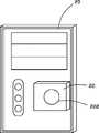
图1为本发明电脑机箱较佳实施方式的示意图。FIG. 1 is a schematic diagram of a preferred embodiment of a computer case of the present invention.
图2为本发明电脑机箱较佳实施方式的一侧面板的内部示意图。FIG. 2 is an internal schematic diagram of a side panel of a preferred embodiment of the computer case of the present invention.
图3为本发明电脑机箱较佳实施方式的前面板的内部示意图。FIG. 3 is an internal schematic view of the front panel of a preferred embodiment of the computer case of the present invention.
图4为本发明电脑机箱另一较佳实施方式的前面板的内部示意图。Fig. 4 is an internal schematic view of the front panel of another preferred embodiment of the computer case of the present invention.
具体实施方式Detailed ways
请共同参照图1至图3,本发明电脑机箱的较佳实施方式包括一大致呈长方体的壳体100,所述壳体100的一侧面板10的内壁上设有一吸热板12、一热电转换模块14及若干散热孔16,所述壳体100的前面板20的内壁上设有一制冷器22,所述制冷器22也可以根据实际散热需要设置在所述壳体100的后面板上。Please refer to Fig. 1 to Fig. 3 together, the preferred implementation mode of the computer case of the present invention comprises a substantially rectangular
其中,所述吸热板12大致为一矩形,其表面设有若干并排设置的波纹状凹槽122,所述吸热板12用于吸取放置于所述壳体100内部的主机板(未示出)上元件所产生的热量,之所以设置所述凹槽122,是为了更好的进行吸热。所述吸热板12的形状也可设计成其他形状,不拘泥于本实施方式。Wherein, the
所述热电转换模块14与所述吸热板12相接触设置,所述热电转换模块14用于将所述吸热板12吸收的热能转化为电能并输出。所述制冷器22通过电源线(未示出)接收所述热电转换模块14输出的电能,以在接收到电能后工作并产生冷空气,所述冷空气再通过其上的出风口222向外吹出,使所述壳体100内部的局域空间形成低温,所述壳体100内主机板上中央处理器的风扇运转会增加所述壳体100内的空气流动,把冷空气传递到整个壳体100的内部,如此反复循环,以此来达到对壳体100散热降温的目的。The
请参照图4,在另一实施方式中,也可以在所述前面板20的内壁上多设置一专门用于促进冷空气流通的鼓风机24,所述鼓风机24设于所述制冷器22的出风口222附近,直接对冷空气进行扩散处理,所述鼓风机24的电能可由所述热电转换模块14提供,也可由设在所述壳体100内部的电源提供,其他实施方式中,所述鼓风机24也可根据具体的散热需要设置于所述壳体100内部的其他位置。Please refer to FIG. 4 , in another embodiment, a
本发明电脑机箱通过所述吸热板12及所述热电转换模块14将其内部产生的热量转化为电能,并驱动所述制冷器22工作产生冷空气,以进一步为所述壳体100内部的主机板进行散热,不但提高了散热效率,还将所述电脑机箱内部元件所产生的热量进行了回收利用,节省了能源的同时也保护了环境,并且成本较低,符合当今社会节能环保的要求。The computer case of the present invention converts the heat generated inside it into electric energy through the
Claims (10)
Priority Applications (2)
| Application Number | Priority Date | Filing Date | Title |
|---|---|---|---|
| CN200910301506ACN101859168A (en) | 2009-04-13 | 2009-04-13 | computer case |
| US12/432,715US7848103B2 (en) | 2009-04-13 | 2009-04-29 | Computer enclosure |
Applications Claiming Priority (1)
| Application Number | Priority Date | Filing Date | Title |
|---|---|---|---|
| CN200910301506ACN101859168A (en) | 2009-04-13 | 2009-04-13 | computer case |
Publications (1)
| Publication Number | Publication Date |
|---|---|
| CN101859168Atrue CN101859168A (en) | 2010-10-13 |
Family
ID=42934205
Family Applications (1)
| Application Number | Title | Priority Date | Filing Date |
|---|---|---|---|
| CN200910301506APendingCN101859168A (en) | 2009-04-13 | 2009-04-13 | computer case |
Country Status (2)
| Country | Link |
|---|---|
| US (1) | US7848103B2 (en) |
| CN (1) | CN101859168A (en) |
Cited By (3)
| Publication number | Priority date | Publication date | Assignee | Title |
|---|---|---|---|---|
| CN110503989A (en)* | 2019-08-29 | 2019-11-26 | 杭州勤语智能科技有限公司 | A kind of solid-state hard disc equipment |
| CN113251846A (en)* | 2021-06-01 | 2021-08-13 | 中国石化集团胜利石油管理局有限公司胜利发电厂 | Thermal power generating unit heat recovery device |
| CN113890248A (en)* | 2021-09-06 | 2022-01-04 | 超音速智能技术(杭州)有限公司 | Protection component of mechanical conveyor belt running motor |
Families Citing this family (19)
| Publication number | Priority date | Publication date | Assignee | Title |
|---|---|---|---|---|
| US8478386B2 (en) | 2006-01-10 | 2013-07-02 | Accuvein Inc. | Practitioner-mounted micro vein enhancer |
| US9492117B2 (en) | 2006-01-10 | 2016-11-15 | Accuvein, Inc. | Practitioner-mounted micro vein enhancer |
| US12295744B2 (en) | 2006-01-10 | 2025-05-13 | Accuvein, Inc. | Micro vein enhancer with two lasers and two optical detectors configured for removing surface topology |
| US12408865B2 (en) | 2006-01-10 | 2025-09-09 | Accuvein Inc. | Vein imaging device with differential image resolution at the center and the extremities of the vein image |
| US10238294B2 (en) | 2006-06-29 | 2019-03-26 | Accuvein, Inc. | Scanned laser vein contrast enhancer using one laser |
| US9854977B2 (en) | 2006-01-10 | 2018-01-02 | Accuvein, Inc. | Scanned laser vein contrast enhancer using a single laser, and modulation circuitry |
| US8838210B2 (en) | 2006-06-29 | 2014-09-16 | AccuView, Inc. | Scanned laser vein contrast enhancer using a single laser |
| US11278240B2 (en) | 2006-01-10 | 2022-03-22 | Accuvein, Inc. | Trigger-actuated laser vein contrast enhancer |
| US12089951B2 (en) | 2006-01-10 | 2024-09-17 | AccuVeiw, Inc. | Scanned laser vein contrast enhancer with scanning correlated to target distance |
| US11253198B2 (en) | 2006-01-10 | 2022-02-22 | Accuvein, Inc. | Stand-mounted scanned laser vein contrast enhancer |
| US8489178B2 (en) | 2006-06-29 | 2013-07-16 | Accuvein Inc. | Enhanced laser vein contrast enhancer with projection of analyzed vein data |
| US10813588B2 (en) | 2006-01-10 | 2020-10-27 | Accuvein, Inc. | Micro vein enhancer |
| US8730321B2 (en) | 2007-06-28 | 2014-05-20 | Accuvein, Inc. | Automatic alignment of a contrast enhancement system |
| US8463364B2 (en) | 2009-07-22 | 2013-06-11 | Accuvein Inc. | Vein scanner |
| US8594770B2 (en) | 2006-06-29 | 2013-11-26 | Accuvein, Inc. | Multispectral detection and presentation of an object's characteristics |
| US20100242523A1 (en)* | 2009-03-31 | 2010-09-30 | Todd Rubright | Electric Cooling System for Electronic Equipment |
| US9061109B2 (en) | 2009-07-22 | 2015-06-23 | Accuvein, Inc. | Vein scanner with user interface |
| US9072426B2 (en) | 2012-08-02 | 2015-07-07 | AccuVein, Inc | Device for detecting and illuminating vasculature using an FPGA |
| US10517483B2 (en) | 2012-12-05 | 2019-12-31 | Accuvein, Inc. | System for detecting fluorescence and projecting a representative image |
Family Cites Families (10)
| Publication number | Priority date | Publication date | Assignee | Title |
|---|---|---|---|---|
| JPH10220909A (en)* | 1996-12-03 | 1998-08-21 | Komatsu Ltd | Fluid temperature control device |
| US5987890A (en)* | 1998-06-19 | 1999-11-23 | International Business Machines Company | Electronic component cooling using a heat transfer buffering capability |
| US6525934B1 (en)* | 1999-04-15 | 2003-02-25 | International Business Machines Corporation | Thermal controller for computer, thermal control method for computer and computer equipped with thermal controller |
| JP3753995B2 (en)* | 2002-03-13 | 2006-03-08 | インターナショナル・ビジネス・マシーンズ・コーポレーション | Cooling device and information processing device |
| TWI260196B (en)* | 2003-11-14 | 2006-08-11 | Qnx Cooling Systems Inc | Liquid cooling system |
| US6917522B1 (en)* | 2003-12-29 | 2005-07-12 | Intel Corporation | Apparatus and method for cooling integrated circuit devices |
| US7903409B2 (en)* | 2007-07-18 | 2011-03-08 | Hewlett-Packard Development Company, L.P. | System and method for cooling an electronic device |
| US8854595B2 (en)* | 2008-03-03 | 2014-10-07 | Manufacturing Resources International, Inc. | Constricted convection cooling system for an electronic display |
| US7764493B2 (en)* | 2008-01-04 | 2010-07-27 | Apple Inc. | Systems and methods for cooling electronic devices using airflow dividers |
| US20100050658A1 (en)* | 2008-08-29 | 2010-03-04 | Apple Inc. | Methods and apparatus for cooling electronic devices using thermoelectric cooling components |
- 2009
- 2009-04-13CNCN200910301506Apatent/CN101859168A/enactivePending
- 2009-04-29USUS12/432,715patent/US7848103B2/ennot_activeExpired - Fee Related
Cited By (4)
| Publication number | Priority date | Publication date | Assignee | Title |
|---|---|---|---|---|
| CN110503989A (en)* | 2019-08-29 | 2019-11-26 | 杭州勤语智能科技有限公司 | A kind of solid-state hard disc equipment |
| CN113251846A (en)* | 2021-06-01 | 2021-08-13 | 中国石化集团胜利石油管理局有限公司胜利发电厂 | Thermal power generating unit heat recovery device |
| CN113251846B (en)* | 2021-06-01 | 2021-09-10 | 中国石化集团胜利石油管理局有限公司胜利发电厂 | Thermal power generating unit heat recovery device |
| CN113890248A (en)* | 2021-09-06 | 2022-01-04 | 超音速智能技术(杭州)有限公司 | Protection component of mechanical conveyor belt running motor |
Also Published As
| Publication number | Publication date |
|---|---|
| US20100259887A1 (en) | 2010-10-14 |
| US7848103B2 (en) | 2010-12-07 |
Similar Documents
| Publication | Publication Date | Title |
|---|---|---|
| CN101859168A (en) | computer case | |
| TWI394524B (en) | Modularized heat dissipating apparatus | |
| CN201075884Y (en) | Radiating device and electronic equipment cabinet | |
| CN202887087U (en) | Semiconductor central processing unit (CPU) radiator having heat insulation protection | |
| CN104679175A (en) | Dustproof radiating machine case | |
| CN203433456U (en) | Water-cooling heat dissipation device for notebook computer | |
| CN210605614U (en) | Heat abstractor for computer machine case | |
| CN106774751B (en) | External surface heat abstractor | |
| CN105607717A (en) | Integrated type radiating system for computer | |
| CN201035493Y (en) | Non-noise liquid cooling computer cabinet | |
| CN201418228Y (en) | Heat sink | |
| CN104020829A (en) | Efficient cooling device for computer case | |
| CN201726609U (en) | Novel heat radiation casing | |
| CN207410664U (en) | A metal heat dissipation shell | |
| CN106855738A (en) | A kind of computer cabinet | |
| CN110955314A (en) | Computer GPU integral type water-cooling radiator | |
| CN105843349A (en) | Radiator | |
| CN206178631U (en) | High -efficient type CPU radiator | |
| CN221930486U (en) | A photovoltaic inverter | |
| CN222532043U (en) | Special-shaped heat pipe combined radiating device of bidirectional power converter | |
| TW201039736A (en) | Computer enclosure | |
| CN202734156U (en) | Electronic control component of air duct machine and air duct machine | |
| CN216252896U (en) | Big data intelligence image scanning device | |
| CN217213547U (en) | Electronic device | |
| CN101742882B (en) | Heat radiation module |
Legal Events
| Date | Code | Title | Description |
|---|---|---|---|
| C06 | Publication | ||
| PB01 | Publication | ||
| C10 | Entry into substantive examination | ||
| SE01 | Entry into force of request for substantive examination | ||
| C02 | Deemed withdrawal of patent application after publication (patent law 2001) | ||
| WD01 | Invention patent application deemed withdrawn after publication | Application publication date:20101013 |