CN101854850B - Imaging catheter with integrated reference reflector - Google Patents
Imaging catheter with integrated reference reflectorDownload PDFInfo
- Publication number
- CN101854850B CN101854850BCN2008801155924ACN200880115592ACN101854850BCN 101854850 BCN101854850 BCN 101854850BCN 2008801155924 ACN2008801155924 ACN 2008801155924ACN 200880115592 ACN200880115592 ACN 200880115592ACN 101854850 BCN101854850 BCN 101854850B
- Authority
- CN
- China
- Prior art keywords
- optical
- image
- oct
- light
- pet
- Prior art date
- Legal status (The legal status is an assumption and is not a legal conclusion. Google has not performed a legal analysis and makes no representation as to the accuracy of the status listed.)
- Active
Links
Images


Classifications
- G—PHYSICS
- G02—OPTICS
- G02B—OPTICAL ELEMENTS, SYSTEMS OR APPARATUS
- G02B23/00—Telescopes, e.g. binoculars; Periscopes; Instruments for viewing the inside of hollow bodies; Viewfinders; Optical aiming or sighting devices
- G02B23/24—Instruments or systems for viewing the inside of hollow bodies, e.g. fibrescopes
- G02B23/2407—Optical details
- G02B23/2423—Optical details of the distal end
- A—HUMAN NECESSITIES
- A61—MEDICAL OR VETERINARY SCIENCE; HYGIENE
- A61B—DIAGNOSIS; SURGERY; IDENTIFICATION
- A61B5/00—Measuring for diagnostic purposes; Identification of persons
- A61B5/0059—Measuring for diagnostic purposes; Identification of persons using light, e.g. diagnosis by transillumination, diascopy, fluorescence
- A61B5/0062—Arrangements for scanning
- A61B5/0066—Optical coherence imaging
- A—HUMAN NECESSITIES
- A61—MEDICAL OR VETERINARY SCIENCE; HYGIENE
- A61B—DIAGNOSIS; SURGERY; IDENTIFICATION
- A61B5/00—Measuring for diagnostic purposes; Identification of persons
- A61B5/68—Arrangements of detecting, measuring or recording means, e.g. sensors, in relation to patient
- A61B5/6846—Arrangements of detecting, measuring or recording means, e.g. sensors, in relation to patient specially adapted to be brought in contact with an internal body part, i.e. invasive
- A61B5/6847—Arrangements of detecting, measuring or recording means, e.g. sensors, in relation to patient specially adapted to be brought in contact with an internal body part, i.e. invasive mounted on an invasive device
- A61B5/6852—Catheters
- G—PHYSICS
- G02—OPTICS
- G02B—OPTICAL ELEMENTS, SYSTEMS OR APPARATUS
- G02B5/00—Optical elements other than lenses
- G02B5/08—Mirrors
Landscapes
- Health & Medical Sciences (AREA)
- Life Sciences & Earth Sciences (AREA)
- Physics & Mathematics (AREA)
- Surgery (AREA)
- General Health & Medical Sciences (AREA)
- Engineering & Computer Science (AREA)
- Biomedical Technology (AREA)
- Heart & Thoracic Surgery (AREA)
- Medical Informatics (AREA)
- Molecular Biology (AREA)
- Biophysics (AREA)
- Animal Behavior & Ethology (AREA)
- Pathology (AREA)
- Public Health (AREA)
- Veterinary Medicine (AREA)
- Astronomy & Astrophysics (AREA)
- General Physics & Mathematics (AREA)
- Optics & Photonics (AREA)
- Nuclear Medicine, Radiotherapy & Molecular Imaging (AREA)
- Radiology & Medical Imaging (AREA)
- Investigating Or Analysing Materials By Optical Means (AREA)
Abstract
Description
Translated fromChinese技术领域technical field
本发明涉及一种光学成像,并且更具体地涉及用于光学相干断层成像(optical coherence tomography)(OCT)的纤维光学探针的设计和相关的成像技术。The present invention relates to optical imaging, and more particularly to the design of fiber optic probes for optical coherence tomography (OCT) and related imaging techniques.
背景技术Background technique
光干涉是一种广泛用于整个科学界的现象。特别地,短相干(或“低相干”)干涉测量成像的使用已经成为许多领域中并且尤其是医疗应用中的一种重要成像模式。在干涉测量成像中,导致来自已知和受控光学路径(光程)(“参考路径”)的光干扰从未知路径返回的光使得关于该未知路径(“样品路径”)的信息可以通过分析所得到的干涉图来确定。Light interference is a phenomenon that is widely used throughout the scientific community. In particular, the use of short coherence (or "low coherence") interferometric imaging has become an important imaging modality in many fields and especially in medical applications. In interferometric imaging, light from a known and controlled optical path (optical path) (“reference path”) is caused to interfere with light returning from an unknown path such that information about that unknown path (“sample path”) can be analyzed The obtained interferogram is determined.
在短相干成像中,干涉图包含进行分析的样品中结构的深度位置信息。在样品体积上扫描短相干光以产生断层分析图像,这被称为光学相干断层成像,或OCT。近年来,具有20μm或更低的相干长度的基于实际激光的光源已经变得可用,促进OCT在包括眼科学、普通显微镜、心脏病学和肿瘤学的许多领域中的使用。In short-coherence imaging, the interferogram contains information about the depth location of structures in the sample under analysis. Scanning short coherent light across the sample volume to produce tomographic images is known as optical coherence tomography, or OCT. In recent years, practical laser-based light sources with coherence lengths of 20 μm or less have become available, facilitating the use of OCT in many fields including ophthalmology, general microscopy, cardiology and oncology.
OCT的一个特定优点是其与纤维光学的固有相容性,使得其成为对于非侵入性或最小侵入性医疗过程的接近理想的成像模式。A particular advantage of OCT is its inherent compatibility with fiber optics, making it a nearly ideal imaging modality for non-invasive or minimally invasive medical procedures.
所有OCT实现的中心问题(central)是要求为了确保干涉效应被记录而匹配的样品和参考路径的长度对应于样品中期望的扫描区域。在许多过程中所需的相对长的光学导管(通常为约1.5~2m)的情况下,对于匹配路径长度的该要求可能会变得难以实现,尤其是当许多实际的OCT实现要求在毫米级上匹配时。而且,在这些导管中使用的非常薄的纤维在使用期间可以容易地伸长或收缩几毫米。Central to all OCT implementations is the requirement that the lengths of the sample and reference paths be matched to the desired scan area in the sample in order to ensure that interference effects are recorded. With the relatively long optical conduits (typically about 1.5-2m) required in many processes, this requirement for matching path lengths can become difficult to achieve, especially when many practical OCT implementations require When matching. Also, the very thin fibers used in these catheters can easily stretch or shrink by a few millimeters during use.
当在任何应用中使用OCT时,光学“零点”是关键的。这定义了在成像空间中存在所谓的参考平面的地方。按照惯例,表面平面处于x-y平面,而深度沿着z-轴出现。在显微镜应用中,例如,在显微镜载玻片的表面上设置零点可能是有利的,这样试样可以相对于该已知表面进行测量。在插入体腔的导管中,最有用的参考平面是导管尖端自身的外表面,并且所有距离都从该位置向外测量。The optical "null point" is critical when using OCT in any application. This defines where in imaging space there exists a so-called reference plane. By convention, the surface plane is in the x-y plane, while depth occurs along the z-axis. In microscopy applications, for example, it may be advantageous to have a zero point on the surface of a microscope slide so that the specimen can be measured relative to this known surface. In a catheter inserted into a body lumen, the most useful reference plane is the outer surface of the catheter tip itself, and all distances are measured outward from this location.
对于旋转的导管,x-y-z空间最好以极坐标(角度和径向距离)表示。因此,z-轴变成距离中心的径向距离。实际上,设置匹配点是指距离样品中所选参考平面的光学长度等于参考臂(referencearm)中的主要光学长度。在扫描中参考臂长度的高速变化仅表示在主长度上的很小变化。因为OCT至多穿透组织仅几毫米,扫描实际上限于典型地1~5mm,而样品和参考臂的实际长度可能是几米。For a rotating catheter, the x-y-z space is best expressed in polar coordinates (angle and radial distance). Thus, the z-axis becomes the radial distance from the center. In practice, setting the matching point means that the optical length from the selected reference plane in the sample is equal to the principal optical length in the reference arm. High speed changes in the length of the reference arm in the scan represent only small changes in the main length. Because OCT penetrates tissue only a few millimeters at best, scanning is practically limited to typically 1-5 mm, while the actual length of the sample and reference arms can be several meters.
例如,在心脏病学中使用的光学导管的情况下,仪器自身将定位在患者周围的名义上的“无菌场所”外部,导管自身将处于该场所内部,并且脐带(umbilical)将用于连接这两者。样品臂(samplearm)的总光学长度(导管+脐带)可以容易地达到5米,这也将是参考臂的主长度。由于扫描将或许是5mm,因此这表示总长度的0.1%。在这种应用中测量精度要求为0.1mm或更好。因为将导管和脐带内的每一光学纤维的长度控制至亚毫米尺寸不是成本有效的,因此最好的设计方法在光学成像设备中使用可调的参考路径以按照每一导管的使用对其进行调节。For example, in the case of optical catheters used in cardiology, the instrumentation itself would be positioned outside a nominally "sterile field" around the patient, the catheter itself would be inside that field, and the umbilical would be used to connect Both. The total optical length (catheter + umbilical) of the sample arm can easily be up to 5 meters, which will also be the main length of the reference arm. Since the scan will be perhaps 5mm, this represents 0.1% of the total length. The measurement accuracy required in this application is 0.1mm or better. Because it is not cost-effective to control the length of each optical fiber within the catheter and umbilical to submillimeter dimensions, the best design approach uses adjustable reference paths in the optical imaging device to map it to each catheter usage. adjust.
然而,医疗应用每天可以使用许多一次性导管;所有都与相同的成像设备对接。因此,尽管主路径长度调节可以十分有效地工作,但是通常需要由理解光学反射模式或OCT将要记录的导管的“标记”的熟练操作者进行初始调节以确定如何调节参考路径从而与导管尖端的外表面相一致。此外,成像零点的调节,或参考平面定位通过调节参考臂的主要路径长度来进行。该调节经常称为参考臂的“z-补偿(z-offset)”并经由简称为z-补偿马达的马达控制。按照惯例,当样品臂长度(导管)按照设计进行精确制造时,仪器的z补偿是零;当导管太短时为负;而当导管太长时为正。However, medical applications use many disposable catheters every day; all interface with the same imaging equipment. Thus, while the main path length adjustment can work quite effectively, initial adjustments by a skilled operator who understands the optical reflectance pattern or the "signature" of the catheter that OCT will record are often required to determine how to adjust the reference path to match the appearance of the catheter tip. The faces are consistent. In addition, adjustment of the imaging zero point, or reference plane positioning, is performed by adjusting the main path length of the reference arm. This adjustment is often referred to as "z-offset" of the reference arm and is controlled via a motor referred to simply as a z-offset motor. By convention, the z-compensation of the instrument is zero when the sample arm length (catheter) is manufactured precisely as designed; negative when the catheter is too short; and positive when the catheter is too long.
这些光学导管典型地具有置于它们的远侧尖端的透镜和反射器结构,以聚焦并引导光用于扫描目的。光典型地通过一个或多个构成导管外结构的透明外壳进行传播。每一界面能够并将导致将由OCT检测的反射。因此,确定这些反射中的哪一个对应于系统期望的光学参考点(“零点”)可能具有挑战性。因为测量是基于该零点设置进行的,因此正确地设置该零点在医疗应用中可以具有显著的重要性。而且,因为可能存在许多间隔较近且类似强度的反射,因此使用检测适当零补偿(“z-补偿”)的软件具有极大问题并且是不可靠的。These optical catheters typically have lens and reflector structures placed at their distal tips to focus and direct light for scanning purposes. Light typically propagates through one or more transparent envelopes that form the outer structure of the catheter. Each interface can and will cause reflections to be detected by OCT. Therefore, it can be challenging to determine which of these reflections corresponds to the system's desired optical reference point ("null point"). Since measurements are made based on this zero point setting, setting this zero point correctly can be of significant importance in medical applications. Also, using software to detect proper zero compensation ("z-compensation") is extremely problematic and unreliable because there may be many closely spaced and similar intensity reflections.
如所提及的,当导管前进或缩回时,光学纤维可以在这些尺度内显著地伸长。例如,利用OCT中使用的标准光学纤维的已知屈服强度,以及导管长度,可以容易地表明在纤维断裂前可以发生10mm的伸长。在实际情况下遇到的典型力将仅导致1mm的伸长或更小,但是许多医疗测量要求1/4毫米或更好的精确度。As mentioned, the optical fiber can elongate significantly within these dimensions as the catheter is advanced or retracted. For example, using the known yield strength of standard optical fibers used in OCT, and the catheter length, it can easily be shown that an elongation of 10 mm can occur before the fiber breaks. Typical forces encountered in practical situations will result in only 1 mm of elongation or less, but many medical measurements require 1/4 mm or better accuracy.
因此,需要一种用于可靠地确定导管的光学匹配点(“零点”)的简单、成本有效的方法。而且,该方法应该与实时视频速率成像相容,使得零点可以随着导管被操纵,缩回或前进,而进行跟踪。本发明解决了这些问题。Therefore, there is a need for a simple, cost-effective method for reliably determining the optical matching point ("null point") of a catheter. Also, the method should be compatible with real-time video rate imaging so that the null point can be tracked as the catheter is maneuvered, retracted or advanced. The present invention solves these problems.
发明内容Contents of the invention
在一个方面,本发明涉及具有细长区段以及近端和远端的纤维光学成像探针,该探针包括施加于远端的薄的受控光学散射材料。In one aspect, the invention relates to a fiber optic imaging probe having an elongated section and a proximal end and a distal end, the probe comprising a thin controlled optical scattering material applied to the distal end.
在另一方面,本发明涉及一种光学元件。该光学元件包括具有第一表面和第二表面的膜。该膜包括聚合物和设置在其中的用于受控光学背散射(反向散射)的至少一个背散射元件。而且,该膜允许透射基本上无失真的成像光。In another aspect, the invention relates to an optical element. The optical element includes a film having a first surface and a second surface. The film includes a polymer and at least one backscattering element disposed therein for controlled optical backscattering (backscattering). Furthermore, the film allows for substantially distortion-free transmission of imaging light.
本文中所描述的本发明的方面可以进一步包括多种实施方式。例如,该光学元件可以进一步包括多个背散射元件,其中所述至少一个背散射元件和所述多个背散射元件中的每一个都是具有颗粒尺寸的颗粒,该多个背散射元件设置在聚合物内。在一个实施方式中,该膜被成形为形成适合于吞没、包围、密封或以其他方式覆盖光学纤维端面或微透镜的曲面。Aspects of the invention described herein may further include various embodiments. For example, the optical element may further comprise a plurality of backscattering elements, wherein each of the at least one backscattering element and the plurality of backscattering elements is a particle having a particle size, the plurality of backscattering elements are disposed on inside the polymer. In one embodiment, the film is shaped to form a curved surface suitable for engulfing, surrounding, sealing or otherwise covering an optical fiber end face or microlens.
在一些优选的实施方式中,颗粒尺寸低于约1.5μm。而且,该颗粒可以包括钛、锌、铝、和/或其他适合于散射光的材料。多个散射元件可以具有按体积计约0.1%掺杂浓度的浓度。光学元件可以进一步包括细长构件,其中该膜被成形以形成外壳,该细长构件设置在该外壳中以形成探针尖端的一部分。In some preferred embodiments, the particle size is below about 1.5 μm. Also, the particles may include titanium, zinc, aluminum, and/or other materials suitable for scattering light. The plurality of scattering elements may have a concentration of about 0.1% doping concentration by volume. The optical element may further comprise an elongate member, wherein the membrane is shaped to form a housing, the elongate member being disposed in the housing to form part of the probe tip.
在另一方面,本发明涉及一种成像探针。该探针包括具有第一端和第二端的细长区段;第二端形成能够腔内成像的探针尖端,该探针尖端包括散射材料,细长区段适于将由散射材料反射的光传送至细长区段的第一端。In another aspect, the invention relates to an imaging probe. The probe includes an elongated section having a first end and a second end; the second end forms a probe tip capable of intracavity imaging, the probe tip includes a scattering material, the elongated section is adapted to convert light reflected by the scattering material Delivered to the first end of the elongated section.
在一个实施方式中,该细长区段是一种光学纤维。细长区段可以是外壳。而且,该探针可以进一步包括设置在外壳中的光学纤维。散射材料可以包括多个分散在基质中的光散射颗粒。散射颗粒可以包括钛和/或其他已知散射光的材料。而且,该基质可以包括聚对苯二甲酸乙二醇酯和/或其他聚合物。In one embodiment, the elongated section is an optical fiber. The elongated section may be the housing. Also, the probe may further include an optical fiber disposed in the housing. The scattering material may comprise a plurality of light scattering particles dispersed in a matrix. The scattering particles may comprise titanium and/or other materials known to scatter light. Also, the matrix may comprise polyethylene terephthalate and/or other polymers.
在另一方面,本发明涉及一种透镜组件。该透镜组件包括微透镜;与该微透镜光学通信的光束引向器(beam director);以及基本上透明的膜。该基本上透明的膜能够双向透射光,并产生受控量的背散射。另外,该膜包围光束引向器的一部分。In another aspect, the invention relates to a lens assembly. The lens assembly includes a microlens; a beam director in optical communication with the microlens; and a substantially transparent film. The substantially transparent film is capable of bi-directionally transmitting light and producing a controlled amount of backscattering. Additionally, the film surrounds a portion of the beam director.
在本发明的一个方面的一个实施方式中,受控量的背散射是至少足以产生用于校准至少一个成像系统参数的成像系统中的参考点的光量。该基本上透明的膜也可以包括多个散射颗粒。该微透镜可以与光学纤维光学通信。而且,该基本上透明的膜可以被成形以形成成像探针尖端。而且,探针尖端可以用于光学相干断层成像(optical coherence tomography imaging)。In one embodiment of an aspect of the invention, the controlled amount of backscatter is at least an amount of light sufficient to create a reference point in the imaging system for calibrating at least one imaging system parameter. The substantially transparent film may also include a plurality of scattering particles. The microlens can be in fiber optic communication. Also, the substantially transparent film can be shaped to form an imaging probe tip. Furthermore, the probe tip can be used for optical coherence tomography imaging.
在又一个方面,本发明涉及一种校准光学相干断层成像系统的方法。该方法包括响应于由样品反射的光来产生扫描数据,该反射的光穿过双向的基本上透明的光学元件;响应于从设置在所述双向的基本上透明的光学元件中的散射元件反射的散射光来产生参考数据;以及响应于所述参考数据来校准所述光学相干断层成像系统以确定随后扫描的相对位置。In yet another aspect, the invention relates to a method of calibrating an optical coherence tomography system. The method includes generating scan data in response to light reflected by the sample, the reflected light passing through a bidirectional substantially transparent optical element; responsive to reflection from a scattering element disposed in the bidirectional substantially transparent optical element generating reference data; and calibrating the optical coherence tomography system in response to the reference data to determine relative positions for subsequent scans.
在本发明的一个方面的一个实施方式中,扫描数据包括一组角度和一组径向距离。而且,该参考数据可以包括一组角度和一组径向距离。校准步骤可以包括搜索参考数据中的环形模式(ringpattern)。In one embodiment of an aspect of the invention, the scan data includes a set of angles and a set of radial distances. Also, the reference data may include a set of angles and a set of radial distances. The calibration step may include searching for ring patterns in the reference data.
在又一个方面,本发明涉及一种制造光学元件的方法。该方法包括选择适合于在动物内腔内使用的膜材料;选择适合于在该膜材料中分散的掺杂剂,该掺杂剂适于响应于光源而散射光;确定掺杂剂体积浓度使得掺杂膜的径向扫描产生所定义的模式(或图案);用所选择的掺杂剂掺杂该膜以基本上获得确定的掺杂剂体积浓度;以及成形用于在动物体内腔内使用的膜。In yet another aspect, the invention relates to a method of manufacturing an optical element. The method includes selecting a membrane material suitable for use in an animal lumen; selecting a dopant suitable for dispersion in the membrane material, the dopant being adapted to scatter light in response to a light source; determining the dopant volume concentration such that radial scanning of the doped film to produce a defined pattern (or pattern); doping the film with a selected dopant to obtain substantially a defined dopant volume concentration; and shaping for use within an animal lumen membrane.
在一个实施方式中,该膜包括聚对苯二甲酸乙二醇酯。掺杂剂体积浓度可以包括按体积计约0.1%的掺杂浓度。所选的掺杂剂可以包括氧化物。而且,所定义的模式可以选自由环形和螺旋形组成的组。In one embodiment, the film comprises polyethylene terephthalate. The dopant volume concentration may include a doping concentration of about 0.1% by volume. Selected dopants may include oxides. Also, the defined pattern may be selected from the group consisting of circular and spiral.
附图说明Description of drawings
图1是适合用于本发明的光学探针的OCT系统的框图;Figure 1 is a block diagram of an OCT system suitable for use with the optical probe of the present invention;
图2是光学导管系统的示意图,适合用于冠状动脉中OCT成像;Figure 2 is a schematic diagram of an optical catheter system suitable for OCT imaging in coronary arteries;
图3是具有微透镜和保护罩的光学纤维尖端的示意图;Figure 3 is a schematic diagram of an optical fiber tip with a microlens and a protective cover;
图3a是在图3中示意性示出的探针的实施方式的显微照片;Figure 3a is a photomicrograph of an embodiment of the probe shown schematically in Figure 3;
图4a和图4b描述了分别采用掺杂塑胶透镜罩和未掺杂塑胶(例如PET)罩拍摄的图像;Fig. 4a and Fig. 4b have described the image that adopts doped plastic lens cover and undoped plastic (such as PET) cover to take respectively;
图4c示出了OCT图像,其中使用了过量浓度的掺杂剂TiO2并且所得的结块导致光学阴影;Figure 4c shows an OCT image where an excess concentration of the dopantTiO2 was used and the resulting agglomeration caused optical shadowing;
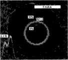
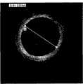
图5a示出了采用合适的扫描线取向和由指示的检测的PET反射的频率域OCT图像;Figure 5a shows that with a suitable scan line orientation and by Frequency-domain OCT images of the indicated detected PET reflections;
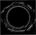
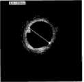
图5b示出了采用反向扫描线取向(或反转状态)和由
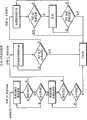
图6是用于检测PET环的算法的实施方式的流程图;Figure 6 is a flowchart of an embodiment of an algorithm for detecting PET rings;
图7是用于设置PET环位置的算法的实施方式的流程图;Figure 7 is a flowchart of an embodiment of an algorithm for setting the position of a PET ring;
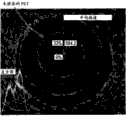
图8示出了使用图1和2中的部件制成的冠状动脉的图像,其中零点补偿被正确设置;Figure 8 shows an image of a coronary artery made using the components in Figures 1 and 2 with the zero point compensation properly set;
图9示出了使用图1和2中的部件制成的冠状动脉的图像,其中零点补偿被不正确地设置(零点太短并在光纤中移动,导致图像远离中心扩展);Figure 9 shows an image of a coronary artery made using the components in Figures 1 and 2, where the null point compensation was set incorrectly (the zero point was too short and moved in the fiber, causing the image to expand away from the center);
图10示出了使用图1和2中的部件制成的冠状动脉的图像,其中零点补偿被不正确地设置(零点太长并移动至光纤外面的点,导致图像朝向中心收缩);以及Figure 10 shows an image of a coronary artery made using the components in Figures 1 and 2, where the zero point compensation was incorrectly set (the zero point was too long and moved to a point outside the fiber, causing the image to shrink towards the center); and
图11示出了显示根据本发明的实施方式的特征性环反射的导管中心的放大OCT图像。Figure 11 shows a magnified OCT image of the center of the catheter showing the characteristic ring reflection according to an embodiment of the invention.
具体实施方式Detailed ways
简而概之并参照图1,示出了一般化的OCT干涉仪10,其适合用于本发明的导管成像系统。光源14(如二极管激光器)产生短相干长度光,该光通过光纤18进入光纤耦合器22。进入耦合器22的光沿着两个光纤路径26和30分裂。一个路径26终止于可移动反射器34,而另一路径进入探针38并朝向感兴趣的对象42发射。Briefly summarized and referring to FIG. 1 , a
由可移动反射器34反射的光沿着光纤26反向传播至耦合器22。类似地,由感兴趣的对象42反射的光沿着光纤30反向传播至耦合器22并与由可移动反射器34反射的光合并以形成干涉图样(interference pattern)。该合并的光传播通过光纤46并由检测器50检测。来自检测器50的输出信号通过电子设备54处理并在显示器58上形成图像。Light reflected by
适合用作图1中探针的成像导管的实例示于图2中。在该实施方式中,成像探针38是冠状血管成像导管的尖端。连接器62连接至图1的系统的光学耦合器22。光纤30进入连接至气囊导管70的y-体连接器66。该导管70包括冲洗端口(flushing port)74和气囊膨胀端口78以及冲洗出口82。An example of an imaging catheter suitable for use as the probe in FIG. 1 is shown in FIG. 2 . In this embodiment,
图3描述了探针38的图像导线尖端的实施方式。光纤30终止于微透镜组件86,该透镜组件聚焦离该微透镜组件86一定距离的光。从微透镜组件86发射的光被光束偏转器90反射,使得以基本上与光纤30的光轴呈直角地通过。整个纤维组件由如下讨论的在一端98处密封的保护性透明外壳94覆盖。FIG. 3 depicts an embodiment of an imaging wire tip of
如在以引用方式结合于本文的美国专利6,891,894中解释的,特别有利的纤维透镜设计从氧化硅-空气界面使用全内反射以通过简单地旋转光纤来提供腔,如动脉内部的所需径向扫描。因为全内反射取决于氧化硅与空气之间的折射率错配,因此在流体中的直接浸没将消除这种反射并且光将反而向前传播,破坏了采取有用径向扫描的能力。如在′894专利以及图3和图3a中所示,空气-氧化硅界面可以通过使用直接附着于光纤透镜组件的清晰保护罩94保护。这样的罩可以优选由热缩材料如聚酯(聚对苯二甲酸乙二醇酯,或PET)制成。PET广泛地用于工业和医疗装置中,并且具有良好的生物医疗相容性性质。As explained in U.S. Patent 6,891,894, incorporated herein by reference, a particularly advantageous fiber lens design uses total internal reflection from the silica-air interface to provide a lumen, such as the desired radial diameter inside an artery, by simply rotating the fiber optic. scanning. Since total internal reflection depends on the refractive index mismatch between silicon oxide and air, direct immersion in the fluid will eliminate this reflection and the light will instead propagate forward, destroying the ability to take a useful radial scan. As shown in the '894 patent and in Figures 3 and 3a, the air-silica interface can be protected by using a clear
这样的PET罩具有内在的低背反射,因此在其通常的形式中,其不适合于提供固定的参考反射的目的。然而,可以将掺杂剂小心地加入到粗PET材料中(在管形状形成前),增加天然的背反射。Such PET masks have inherently low back reflections and are therefore unsuitable for the purpose of providing a fixed reference reflection in their usual form. However, dopants can be carefully added to the crude PET material (before the tube shape is formed) to increase the natural back reflection.
作为合适的掺杂剂存在几种材料。尤其是,二氧化钛(TiO2)是有利的。由于其优异的光散射性能,TiO2被用于许多涂料制剂中。而且,其是惰性的并且可以散装制成。颗粒尺寸可以制作成比感兴趣的光学波长(标称1.3μm)更小,在本质上形成散射“瑞利(Rayleigh)”。因此,输出和返回光的波前并未明显受到干扰,由此以足够低浓度的掺杂剂使任何潜在的图像降级得到最小化。Several materials exist as suitable dopants. In particular, titanium dioxide (TiO2 ) is advantageous. Due to its excellent light scattering properties,TiO2 is used in many coating formulations. Also, it is inert and can be made in bulk. The particle size can be made smaller than the optical wavelength of interest (nominally 1.3 μm), creating a scattering "Rayleigh" in nature. Thus, the wavefronts of the output and return light are not significantly disturbed, thereby minimizing any potential image degradation at sufficiently low concentrations of dopants.
在形成材料中的关键步骤是在粗PET中均匀地混合TiO2颗粒,使得当将PET拉制成管时,以高的均匀性实现精确的浓度。另外,因为OCT成像具有极大的灵敏度和较大的动态范围(典型地为100dB的灵敏度和>60dB的动态范围可以在实际仪器中实现),因此必须小心计算才能在材料中实现最佳掺杂水平的TiO2。A critical step in forming the material is to uniformly mix theTiO2 particles in the crude PET so that when the PET is drawn into a tube, a precise concentration is achieved with high uniformity. In addition, because OCT imaging has extreme sensitivity and large dynamic range (typically 100dB sensitivity and >60dB dynamic range can be achieved in practical instruments), careful calculations must be made to achieve optimal doping in the material level of TiO2 .
基本散射理论可以用于达到材料中的掺杂浓度。在冠状动脉的典型OCT成像中,仪器中的最小噪声为约-100dB。即,约1个十亿分之十的光输出功率施加于感兴趣的对象,而典型的图像具有约40dB的有用动态范围。对于该范围优化图像处理电子设备和软件,因此探针反射器元件应该被优化以接近图像强度的最大可检测峰,其为约-60dB(-100+40)。这意味着探针反射器应该是图像中的最明亮的对象。Basic scattering theory can be used to arrive at doping concentrations in materials. In typical OCT imaging of coronary arteries, the minimum noise in the instrument is about -100 dB. That is, about 1 part per billion of optical output power is applied to the object of interest, while a typical image has a useful dynamic range of about 40 dB. The image processing electronics and software are optimized for this range, so the probe reflector element should be optimized to be close to the maximum detectable peak of the image intensity, which is about -6OdB (-100+40). This means that the probe reflector should be the brightest object in the image.
如本文中所描述的,探针反射器元件可以包括但不限于,膜、薄膜、盖、罩、或其他材料。在一些实施方式中,反射器元件是弯曲的或不可弯曲的。反射器元件可以被成形为各种几何形状,使得反射器的各部分是弯曲的、平坦的或基本上平坦的。As described herein, probe reflector elements may include, but are not limited to, films, films, covers, covers, or other materials. In some embodiments, the reflector element is curved or non-bendable. The reflector elements may be shaped in various geometries such that portions of the reflector are curved, flat or substantially flat.
颗粒的基本散射理论和经典的雷达截面理论估计,由单个TiO2颗粒反射的光分数由以下表达式给出:Estimated by the basic scattering theory of particles and the classical radar cross section theory, the fraction of light reflected by a singleTiO2 particle is given by the following expression:
其中LR是返回光分数,σb是散射截面(由标准MIE理论计算),Vi是颗粒的体积,lc是相互作用长度(来自雷达理论),在这种情况下,OCT光的相干长度,以及ΔΩ是微透镜的受光角(立体角)。因此,对于散射截面为约4.26×10⁻⁷μm2的大约45nm的颗粒尺寸,以及辐射颗粒通过立体角为~0.004微透镜的具有约15μm相干长度的光,反射光分数LR为约0.006,或-32dB。whereLR is the return light fraction,σb is the scattering cross section (calculated from standard MIE theory),V is the volume of the particle,lc is the interaction length (from radar theory), in this case the coherence of OCT light length, and ΔΩ is the acceptance angle (solid angle) of the microlens. Thus, for a particle size of about 45 nm with a scattering cross-section of about 4.26×10⁻⁷ μm, and light having a coherence length of about 15 μm irradiating the particle through a microlens with a solid angle of ∼0.004, the reflected light fractionLR is about 0.006, or -32dB.
因此,从探针参考反射器元件材料返回的总光应该等于单个颗粒光分数乘以体积分数(掺杂浓度)。由于这应该等于约-60dB(如上),因而需要-30dB(或0.001)的降低。因此,体积分数应该为按体积计约0.001,或约0.1%的掺杂浓度。这应导致由TiO2颗粒产生强的但并非太强的参考反射。Therefore, the total light return from the probe reference reflector element material should be equal to the individual particle light fraction multiplied by the volume fraction (doping concentration). Since this should equal about -60dB (as above), a -30dB (or 0.001) reduction is required. Therefore, the volume fraction should be about 0.001 by volume, or a doping concentration of about 0.1%. This should result in a strong but not too strong reference reflection from theTiO2 particles.
当零点补偿位置稳定时,与未掺杂的罩(图4b)相比,掺杂的PET材料在如图4a所示的图像中产生一致的明亮环。当零点补偿位置不稳定时,在正常使用期间通过有目的地改变参考路径长度或通过拉伸或压缩纤维,环形更似螺旋形。如果TiO2颗粒的浓度过高,则可以由于结块而产生颗粒投射阴影,如图4c所示。在一个实施方式中,探针反射器元件是能够透射基本上无失真的成像光的膜。术语“基本上无失真的成像光”是指适合于产生样品或样品元件的图像的光。When the zero compensation position is stable, the doped PET material produces a consistent bright ring in the image shown in Figure 4a compared to the undoped mask (Figure 4b). When the zero compensation position is unstable, the loop is more helical during normal use by purposefully changing the reference path length or by stretching or compressing the fiber. If the concentration ofTiO2 particles is too high, particle cast shadows can be produced due to agglomeration, as shown in Fig. 4c. In one embodiment, the probe reflector element is a film capable of transmitting imaged light substantially without distortion. The term "substantially distortion-free imaging light" refers to light suitable for producing an image of a sample or sample element.
以“原始”格式捕获的数据是一系列径向扫描,每一个都以均匀间隔的角度出现,极其像脚踏车轮中的辐条。原始数据简单地以传统矩阵记忆格式(储存格式)存储,其中列表示角度,而每行是特定的径向距离。因此,储存在内存中的完美圆形的图像将会对于每一列沿着相同行出现,即,具有零(平坦)斜率的直线。螺旋模式储存为具有一定斜率的直线,如果螺旋膨胀则为正,如果螺旋收缩则为负。Data captured in "raw" format is a series of radial scans, each at evenly spaced angles, much like the spokes in a bicycle wheel. The raw data is simply stored in a traditional matrix memory format (storage format), where the columns represent angles and each row is a specific radial distance. Thus, the perfectly circular image stored in memory will appear along the same row for each column, ie, a straight line with zero (flat) slope. The helical pattern is stored as a straight line with a slope that is positive if the helix expands and negative if the helix contracts.
因此,来自PET材料的信号在图像中产生可能具有平坦、正或负斜率的线,这取决于光路径长度是否是恒定的、增加的或减小的。于是斜率大小与在拉伸或收缩的方向上纤维路径长度变化的速率成比例。因为现在零点补偿位置是可检测的,因此可以通过利用其明亮反射、已知的厚度和内存中的期望直线表象,应用软件算法来分离PET环。Thus, the signal from the PET material produces a line in the image that may have a flat, positive or negative slope, depending on whether the optical path length is constant, increasing or decreasing. The magnitude of the slope is then proportional to the rate at which the fiber path length changes in the direction of stretching or shrinking. Since the zero compensation position is now detectable, a software algorithm can be applied to separate the PET rings by utilizing their bright reflection, known thickness and expected straight line appearance in memory.
在频率域OCT系统中,斜率符号也必须加以考虑。由于频率混叠效应,OCT图像可以在一定的z-补偿马达轨迹范围内反向出现。正确取向的图像在图5a中示出(其中检测的PET如短华线所示),而反向图像在图5b中示出。在反向图像中,扫描线反转,因此靠近原点的目标出现在外围,而在外围中的目标出现在原点附近。当图像倒置时,PET信号的斜率具有与取向正常时相反的符号(反转状态)。该事实可以用于确定图像的取向。In frequency-domain OCT systems, the sign of the slope must also be considered. Due to frequency aliasing effects, OCT images can appear inversely within a certain range of z-compensated motor trajectories. The correctly oriented image is shown in Figure 5a (where the detected PET is shown as a dashed line), while the reversed image is shown in Figure 5b. In a reversed image, the scan lines are reversed so objects near the origin appear in the periphery, and objects in the periphery appear near the origin. When the image is inverted, the slope of the PET signal has the opposite sign (inverted state) than when the orientation is normal. This fact can be used to determine the orientation of the image.
算法的基本步骤在图6中示出。获得OCT图像(步骤1)并在统计的基础上首先进行分析。该分析对于每一给定的强度值而计算像素数目。随后采用直方图来产生“全局阈值(Global Threshold)”值以从背景噪声中分离前景组织(步骤2)。因为图像强度将实际上下降到背景噪声水平,因此较大径向距离的强度可以用于估计系统的总“本底噪声(noise-floor)”。随后这个值用于产生二进制图像(步骤3)。阈值以上的强度值设置为1;低于阈值的那些强度值设为0。通过分析二进制图像而不是输出的OCT图像,最小化对掺杂PET反射绝对水平的依赖性。The basic steps of the algorithm are shown in FIG. 6 . OCT images are acquired (step 1) and first analyzed on a statistical basis. The analysis counts the number of pixels for each given intensity value. The histogram was then employed to generate a "Global Threshold" value to separate foreground tissue from background noise (step 2). Since the image intensity will actually drop down to the background noise level, the intensity at larger radial distances can be used to estimate the total "noise-floor" of the system. This value is then used to generate a binary image (step 3). Intensity values above the threshold are set to 1; those below the threshold are set to 0. The dependence on the absolute level of doped PET reflection is minimized by analyzing the binary image rather than the output OCT image.
一旦二进制图像可以利用,则采用设计为对于厚度类似于已知PET层厚度的信号和邻近黑空间具有峰值响应的一维空间滤波器滤波(步骤4)。如图中所示,组织的影响通过空间滤波器被大大最小化,而保存了PET环。Once the binary image is available, it is filtered with a one-dimensional spatial filter designed to have a peak response for signals of thickness similar to the known PET layer thickness and adjacent black space (step 4). As shown in the figure, the effect of tissue is greatly minimized by the spatial filter, while the PET ring is preserved.
关于时间域OCT系统,图像被假设为具有标准取向而省略步骤5。相反,关于频率域OCT系统,在处理过程中的下一步骤(步骤5)将会通过根据一起平均所有过滤图像的扫描线而计算整个过滤图像的代表性扫描线来确定图像的取向。这种平均处理将预计的斜率S考虑在内并相对于其邻近对扫描线位置进行线性调节,以使倾斜的PET信号横穿所有的这些线而构造性地添加。这种“斜率校正的”平均线也可以采用相反斜率-S计算以观察哪一结果产生最强的峰值信号。如果采用S校正产生最佳结果,则框架正确取向(图5a)并应该使用该框架。如果采用-S(或负S)校正产生最佳结果,则框架反转(图5b),并且应该弃之。因此,在某些校准或取向方法的实施方式中,负斜率值、反转状态,或关于或指示相同情况的某些模式可以在来自OCT扫描的某些原始数据中检测并且用于校准OCT系统(或其部件)。Regarding the time-domain OCT system, the images are assumed to have a standard orientation and step 5 is omitted. In contrast, with frequency domain OCT systems, the next step in the process (step 5) will determine the orientation of the image by computing a representative scanline of the entire filtered image from averaging the scanlines of all filtered images together. This averaging takes into account the expected slope S and linearly adjusts the scanline position relative to its neighbourhood, so that the sloped PET signal is constructively added across all of these lines. This "slope corrected" mean line can also be calculated with opposite slopes -S to see which results in the strongest peak signal. If applying the S correction yields the best results, then the frame is correctly oriented (Fig. 5a) and should be used. If applying -S (or negative S) correction yields the best results, the frame is inverted (Fig. 5b) and should be discarded. Thus, in certain calibration or orientation method embodiments, negative slope values, inversion states, or certain patterns related to or indicative of the same can be detected in certain raw data from OCT scans and used to calibrate the OCT system (or its parts).
在处理过程中的下一步(第6步)是在过滤的二进制图像的每一象限中一起平均所有的扫描线从而产生每个象限的一个代表性扫描线。这就意味着,在存储的内存中,列分成四个等组,而对于每组,所有的列都一起跨行平均从而对于初始图像的四个90度象限中的每一个都产生一个代表性列。该过程起到强调作为同心或近同心的图像内容的作用。在一个象限基础上进行平均,与全360度相反,使得来自移动参考路径的PET信号(其会是螺旋形的)并未在求和过程中丢失。所得的四个平均线每一个都用简单矩形窗滤波器(boxcar filter)进行平滑化,而在每个之上定位最明亮的三个峰。The next step in the process (step 6) is to average all the scanlines together in each quadrant of the filtered binary image to produce a representative scanline for each quadrant. This means that, in stored memory, the columns are divided into four equal groups, and for each group, all the columns are averaged together across the rows to produce a representative column for each of the four 90-degree quadrants of the original image . This process serves to emphasize image content that is concentric or nearly concentric. Averaging is done on a quadrant basis, as opposed to full 360 degrees, so that the PET signal (which would be spiral) from the moving reference path is not lost in the summation process. The resulting four mean lines were each smoothed with a simple boxcar filter, with the three brightest peaks located above each.
最后,在下一步骤(步骤7)中,选择来自每一象限平均线的峰值使得一起形成最佳环。采用递归算法通过首先计算四点总和并随后计算采用最小二乘拟合(least squares fit)算法拟合该点的线均方误差(MSE)来分析每一可能组。所得的MSE结合四点的总和以形成得分(score)。该得分起到强调明亮的(更大和)和平坦的(更小MSE)可能环的作用。具有最大得分的组选择作为优胜者,并且将其和与截止值相比以确定该结果是否有效。Finally, in the next step (step 7), the peaks from each quadrant mean line are chosen such that together they form the best ring. Each possible group was analyzed using a recursive algorithm by first computing the four-point sum and then computing the mean square error (MSE) of the line fitted to the point using the least squares fit algorithm. The resulting MSE combines the sum of the four points to form a score. This score serves to highlight bright (larger sum) and flat (smaller MSE) possible rings. The group with the largest score is selected as the winner, and its sum is compared to a cutoff value to determine if the result is valid.
在操作中,当新的成像导管连接到该系统时,初始粗略校准通过旋转纤维并调节参考路径控制马达来进行,如图7所示。在参考臂中的z-补偿马达开始在其界限之间高速扫过(步骤10),而同时搜索PET环。一旦发现该环,马达速率就减慢(步骤12),并且PET图像就靠近其所需位置(零点,本文中称之为“松弛范围”)移动。In operation, when a new imaging catheter is connected to the system, an initial coarse calibration is performed by rotating the fiber and adjusting the reference path control motor, as shown in FIG. 7 . The z-compensation motor in the reference arm begins to sweep between its limits at high speed (step 10), while simultaneously searching for the PET ring. Once the loop is found, the motor speed is slowed (step 12) and the PET image is moved closer to its desired location (zero point, referred to herein as the "relaxation range").
而且,一旦处于松弛范围内,马达就按步移动(步骤14)直至PET图像处于其最后容许的范围(“紧缩范围”)。在现场扫描期间,z-补偿可稍微漂移,导致PET向紧缩范围之外移动。当发生这种情况时,马达就再次启动而将PET按步移动回到紧缩范围。紧缩范围限额是通过所需的测定精度和恒定z-补偿马达移动最小化所设定的平衡值。Also, once in the relaxed range, the motor is moved in steps (step 14) until the PET image is in its last allowed range ("tight range"). During live scanning, the z-compensation can drift slightly, causing the PET to move out of the tight range. When this happens, the motor is turned on again to move the PET back into the tightening range in steps. The tight range limit is a balance set by the desired measurement accuracy and constant z-compensation motor movement minimization.
在实时成像期间,PET环,如通过优胜组的最小二乘拟合线定义的,在固定位置(半径)基于微透镜组件中PET的已知物理位置显示在显示屏上。每一图像框架的z补偿调进或调出以使PET环终结于所需位置。During real-time imaging, PET rings, as defined by the least-squares fitted lines of the winning set, were displayed on the display at fixed positions (radii) based on the known physical location of the PET in the microlens assembly. The z-compensation for each image frame is toggled in or out so that the PET loop ends up at the desired position.
最后的结果是z-补偿校正的图像显示在显示屏上并存储在保存图像文件中,容许校正按照直进模式实施的临床测定结果。图8是冠状动脉的OCT成像,其中z补偿正确设定。脉管直径由此正确测定为2.55mm。图9是冠状动脉的OCT成像,其中z补偿不正确设定使得z-补偿定位于透镜组件内。脉管直径由此不正确地测定为2.97mm。The final result is a z-compensated corrected image displayed on the display and stored in a save image file, allowing correction of clinical assay results performed in a straight-through mode. Figure 8 is an OCT image of a coronary artery with z compensation correctly set. The vessel diameter was thus correctly determined to be 2.55 mm. Figure 9 is an OCT image of a coronary artery where the z-compensation is incorrectly set such that the z-compensation is located within the lens assembly. The vessel diameter was thus incorrectly determined to be 2.97 mm.
图10是冠状动脉的OCT成像,其中z补偿不正确设定使得z-补偿定位在保护性PET罩之外。脉管直径由此不正确地测定为2.00mm。因此,本发明提供了一种用于确定OCT干涉仪中参考和样品路径均等化的方法,而由此提供了感兴趣的目标的精确测定。Figure 10 is an OCT image of a coronary artery where the z-compensation was incorrectly set such that the z-compensation was positioned outside the protective PET mask. The vessel diameter was thus incorrectly determined to be 2.00 mm. Accordingly, the present invention provides a method for determining the equalization of reference and sample paths in an OCT interferometer, thereby providing accurate determination of objects of interest.
图11是根据本发明各方面产生的另一OCT图像。具体地,其是显示由微透镜PET层(最里层)100和图像导线塑胶外壳(中间)102产生的特征环反射的导管中心的放大OCT图像。外环104对应于塑胶管的内壁边沿,图像导线插入其中以产生图11中所示图像。然而,由于管的厚度,外壁边沿在图像中并不可见。Fig. 11 is another OCT image produced in accordance with aspects of the present invention. Specifically, it is a magnified OCT image of the center of the catheter showing the characteristic ring reflection produced by the microlensed PET layer (innermost layer) 100 and the image lead plastic housing (middle) 102 . The
在图11中,PET环采用标准的未掺杂的PET产生。如所示出的,图像导线压在管的侧面上由此导致第三外环104变成非同心的。In Figure 11, the PET ring was produced using standard undoped PET. As shown, the image wires press against the sides of the tube thereby causing the third
应该理解到,以上描述的实施方式和以下的实施例通过举例说明而非限制性给出。本发明范围内的各种变化和修改对于本发明描述的领域内那些技术人员而言将是显而易见的。It should be understood that the embodiments described above and the examples below are given by way of illustration and not limitation. Various changes and modifications within the scope of the invention will become apparent to those skilled in the art to which the invention is described.
Claims (5)
Applications Claiming Priority (3)
| Application Number | Priority Date | Filing Date | Title |
|---|---|---|---|
| US11/983,526 | 2007-11-12 | ||
| US11/983,526US7813609B2 (en) | 2007-11-12 | 2007-11-12 | Imaging catheter with integrated reference reflector |
| PCT/US2008/012701WO2009064410A2 (en) | 2007-11-12 | 2008-11-12 | Imaging catheter with integrated reference reflector |
Related Child Applications (1)
| Application Number | Title | Priority Date | Filing Date |
|---|---|---|---|
| CN201210269037.5ADivisionCN102783937B (en) | 2007-11-12 | 2008-11-12 | Optical coherence tomography (OCT) and related imaging method |
Publications (2)
| Publication Number | Publication Date |
|---|---|
| CN101854850A CN101854850A (en) | 2010-10-06 |
| CN101854850Btrue CN101854850B (en) | 2012-09-05 |
Family
ID=40340624
Family Applications (2)
| Application Number | Title | Priority Date | Filing Date |
|---|---|---|---|
| CN201210269037.5AActiveCN102783937B (en) | 2007-11-12 | 2008-11-12 | Optical coherence tomography (OCT) and related imaging method |
| CN2008801155924AActiveCN101854850B (en) | 2007-11-12 | 2008-11-12 | Imaging catheter with integrated reference reflector |
Family Applications Before (1)
| Application Number | Title | Priority Date | Filing Date |
|---|---|---|---|
| CN201210269037.5AActiveCN102783937B (en) | 2007-11-12 | 2008-11-12 | Optical coherence tomography (OCT) and related imaging method |
Country Status (6)
| Country | Link |
|---|---|
| US (4) | US7813609B2 (en) |
| EP (2) | EP3045108B1 (en) |
| JP (2) | JP5093787B2 (en) |
| CN (2) | CN102783937B (en) |
| ES (1) | ES2748041T3 (en) |
| WO (1) | WO2009064410A2 (en) |
Families Citing this family (176)
| Publication number | Priority date | Publication date | Assignee | Title |
|---|---|---|---|---|
| US9867530B2 (en) | 2006-08-14 | 2018-01-16 | Volcano Corporation | Telescopic side port catheter device with imaging system and method for accessing side branch occlusions |
| US7935060B2 (en) | 2006-11-08 | 2011-05-03 | Lightlab Imaging, Inc. | Opto-acoustic imaging devices and methods |
| US9596993B2 (en)* | 2007-07-12 | 2017-03-21 | Volcano Corporation | Automatic calibration systems and methods of use |
| EP2178442B1 (en) | 2007-07-12 | 2017-09-06 | Volcano Corporation | Catheter for in vivo imaging |
| WO2009009802A1 (en) | 2007-07-12 | 2009-01-15 | Volcano Corporation | Oct-ivus catheter for concurrent luminal imaging |
| US7813609B2 (en) | 2007-11-12 | 2010-10-12 | Lightlab Imaging, Inc. | Imaging catheter with integrated reference reflector |
| US8582934B2 (en) | 2007-11-12 | 2013-11-12 | Lightlab Imaging, Inc. | Miniature optical elements for fiber-optic beam shaping |
| JP5069585B2 (en)* | 2008-02-25 | 2012-11-07 | 富士フイルム株式会社 | Optical tomographic imaging system using an optical probe |
| US8696695B2 (en) | 2009-04-28 | 2014-04-15 | Avinger, Inc. | Guidewire positioning catheter |
| US8062316B2 (en) | 2008-04-23 | 2011-11-22 | Avinger, Inc. | Catheter system and method for boring through blocked vascular passages |
| US9125562B2 (en) | 2009-07-01 | 2015-09-08 | Avinger, Inc. | Catheter-based off-axis optical coherence tomography imaging system |
| US9788790B2 (en) | 2009-05-28 | 2017-10-17 | Avinger, Inc. | Optical coherence tomography for biological imaging |
| DE102008045634A1 (en) | 2008-09-03 | 2010-03-04 | Ludwig-Maximilians-Universität München | Wavelength tunable light source |
| WO2011003006A2 (en) | 2009-07-01 | 2011-01-06 | Avinger, Inc. | Atherectomy catheter with laterally-displaceable tip |
| US8526472B2 (en) | 2009-09-03 | 2013-09-03 | Axsun Technologies, Inc. | ASE swept source with self-tracking filter for OCT medical imaging |
| US8670129B2 (en) | 2009-09-03 | 2014-03-11 | Axsun Technologies, Inc. | Filtered ASE swept source for OCT medical imaging |
| US12426789B2 (en) | 2009-09-23 | 2025-09-30 | Lightlab Imaging, Inc. | Blood vessel lumen morphology and minimum lumen area measurements data collection by intravascular imaging systems for stenosis or stent planning |
| EP2742858B1 (en) | 2009-09-23 | 2024-06-05 | Light-Lab Imaging Inc. | Lumen morphology and vascular resistance measurements data collection systems, apparatus and methods |
| CA2765410C (en)* | 2009-09-23 | 2015-05-05 | Lightlab Imaging, Inc. | Apparatus, systems, and methods of in-vivo blood clearing in a lumen |
| WO2011072068A2 (en) | 2009-12-08 | 2011-06-16 | Avinger, Inc. | Devices and methods for predicting and preventing restenosis |
| US8206377B2 (en)* | 2009-12-22 | 2012-06-26 | Lightlab Imaging, Inc. | Torque limiter for an OCT catheter |
| US8926590B2 (en) | 2009-12-22 | 2015-01-06 | Lightlab Imaging, Inc. | Torque limiter for an OCT catheter |
| WO2011084863A2 (en) | 2010-01-07 | 2011-07-14 | Cheetah Omni, Llc | Fiber lasers and mid-infrared light sources in methods and systems for selective biological tissue processing and spectroscopy |
| ES2645392T3 (en) | 2010-03-17 | 2017-12-05 | Lightlab Imaging, Inc. | Methods and apparatus for intensity noise reduction for interferometric detection and imaging systems |
| JP5485760B2 (en)* | 2010-03-26 | 2014-05-07 | テルモ株式会社 | Optical coherence tomographic image forming apparatus and control method thereof |
| US9345510B2 (en) | 2010-07-01 | 2016-05-24 | Avinger, Inc. | Atherectomy catheters with longitudinally displaceable drive shafts |
| US10548478B2 (en) | 2010-07-01 | 2020-02-04 | Avinger, Inc. | Balloon atherectomy catheters with imaging |
| WO2014039096A1 (en) | 2012-09-06 | 2014-03-13 | Avinger, Inc. | Re-entry stylet for catheter |
| US11382653B2 (en) | 2010-07-01 | 2022-07-12 | Avinger, Inc. | Atherectomy catheter |
| US11141063B2 (en) | 2010-12-23 | 2021-10-12 | Philips Image Guided Therapy Corporation | Integrated system architectures and methods of use |
| US11040140B2 (en) | 2010-12-31 | 2021-06-22 | Philips Image Guided Therapy Corporation | Deep vein thrombosis therapeutic methods |
| US8582619B2 (en) | 2011-03-15 | 2013-11-12 | Lightlab Imaging, Inc. | Methods, systems, and devices for timing control in electromagnetic radiation sources |
| EP2691038B1 (en) | 2011-03-28 | 2016-07-20 | Avinger, Inc. | Occlusion-crossing devices, imaging, and atherectomy devices |
| US9949754B2 (en) | 2011-03-28 | 2018-04-24 | Avinger, Inc. | Occlusion-crossing devices |
| US9164240B2 (en) | 2011-03-31 | 2015-10-20 | Lightlab Imaging, Inc. | Optical buffering methods, apparatus, and systems for increasing the repetition rate of tunable light sources |
| US20140094697A1 (en) | 2011-05-27 | 2014-04-03 | Lightlab Imaging, Inc. | Optical coherence tomography and pressure based systems and methods |
| CN103959043B (en) | 2011-05-31 | 2016-11-02 | 光学实验室成像公司 | Multimodal imaging systems, devices and methods |
| US8582109B1 (en) | 2011-08-01 | 2013-11-12 | Lightlab Imaging, Inc. | Swept mode-hopping laser system, methods, and devices for frequency-domain optical coherence tomography |
| US10648918B2 (en) | 2011-08-03 | 2020-05-12 | Lightlab Imaging, Inc. | Systems, methods and apparatus for determining a fractional flow reserve (FFR) based on the minimum lumen area (MLA) and the constant |
| US9360630B2 (en) | 2011-08-31 | 2016-06-07 | Volcano Corporation | Optical-electrical rotary joint and methods of use |
| EP3653151A1 (en) | 2011-10-17 | 2020-05-20 | Avinger, Inc. | Atherectomy catheters and non-contact actuation mechanism for catheters |
| US8953911B1 (en) | 2011-10-28 | 2015-02-10 | Lightlab Imaging, Inc. | Spectroscopic imaging probes, devices, and methods |
| US8831321B1 (en) | 2011-11-07 | 2014-09-09 | Lightlab Imaging, Inc. | Side branch detection methods, systems and devices |
| US9345406B2 (en) | 2011-11-11 | 2016-05-24 | Avinger, Inc. | Occlusion-crossing devices, atherectomy devices, and imaging |
| EP2849660B1 (en) | 2012-05-14 | 2021-08-25 | Avinger, Inc. | Atherectomy catheter drive assemblies |
| US9557156B2 (en) | 2012-05-14 | 2017-01-31 | Avinger, Inc. | Optical coherence tomography with graded index fiber for biological imaging |
| WO2013172970A1 (en) | 2012-05-14 | 2013-11-21 | Avinger, Inc. | Atherectomy catheters with imaging |
| US11284916B2 (en) | 2012-09-06 | 2022-03-29 | Avinger, Inc. | Atherectomy catheters and occlusion crossing devices |
| US9498247B2 (en) | 2014-02-06 | 2016-11-22 | Avinger, Inc. | Atherectomy catheters and occlusion crossing devices |
| US9286673B2 (en) | 2012-10-05 | 2016-03-15 | Volcano Corporation | Systems for correcting distortions in a medical image and methods of use thereof |
| US11272845B2 (en) | 2012-10-05 | 2022-03-15 | Philips Image Guided Therapy Corporation | System and method for instant and automatic border detection |
| US9858668B2 (en) | 2012-10-05 | 2018-01-02 | Volcano Corporation | Guidewire artifact removal in images |
| US9307926B2 (en) | 2012-10-05 | 2016-04-12 | Volcano Corporation | Automatic stent detection |
| US20140100454A1 (en) | 2012-10-05 | 2014-04-10 | Volcano Corporation | Methods and systems for establishing parameters for three-dimensional imaging |
| US10070827B2 (en) | 2012-10-05 | 2018-09-11 | Volcano Corporation | Automatic image playback |
| US10568586B2 (en) | 2012-10-05 | 2020-02-25 | Volcano Corporation | Systems for indicating parameters in an imaging data set and methods of use |
| US9324141B2 (en) | 2012-10-05 | 2016-04-26 | Volcano Corporation | Removal of A-scan streaking artifact |
| US9367965B2 (en) | 2012-10-05 | 2016-06-14 | Volcano Corporation | Systems and methods for generating images of tissue |
| US9292918B2 (en) | 2012-10-05 | 2016-03-22 | Volcano Corporation | Methods and systems for transforming luminal images |
| CA2887421A1 (en) | 2012-10-05 | 2014-04-10 | David Welford | Systems and methods for amplifying light |
| US9840734B2 (en) | 2012-10-22 | 2017-12-12 | Raindance Technologies, Inc. | Methods for analyzing DNA |
| JP6153721B2 (en)* | 2012-11-15 | 2017-06-28 | 医療法人社団清友会 | Guide jig |
| EP2919658B1 (en) | 2012-11-19 | 2024-03-20 | Lightlab Imaging, Inc. | Interface devices, systems and methods for multimodal probes |
| EP2929327B1 (en) | 2012-12-05 | 2019-08-14 | Perimeter Medical Imaging, Inc. | System and method for wide field oct imaging |
| EP2931115B1 (en) | 2012-12-12 | 2017-07-26 | Lightlab Imaging, Inc. | Apparatus for automated determination of a lumen contour of a blood vessel |
| EP2931132B1 (en) | 2012-12-13 | 2023-07-05 | Philips Image Guided Therapy Corporation | System for targeted cannulation |
| EP2934310A4 (en) | 2012-12-20 | 2016-10-12 | Nathaniel J Kemp | Optical coherence tomography system that is reconfigurable between different imaging modes |
| WO2014113188A2 (en) | 2012-12-20 | 2014-07-24 | Jeremy Stigall | Locating intravascular images |
| US10939826B2 (en) | 2012-12-20 | 2021-03-09 | Philips Image Guided Therapy Corporation | Aspirating and removing biological material |
| EP2934311B1 (en) | 2012-12-20 | 2020-04-15 | Volcano Corporation | Smooth transition catheters |
| US10942022B2 (en)* | 2012-12-20 | 2021-03-09 | Philips Image Guided Therapy Corporation | Manual calibration of imaging system |
| US11406498B2 (en) | 2012-12-20 | 2022-08-09 | Philips Image Guided Therapy Corporation | Implant delivery system and implants |
| US9486143B2 (en) | 2012-12-21 | 2016-11-08 | Volcano Corporation | Intravascular forward imaging device |
| EP2934323A4 (en) | 2012-12-21 | 2016-08-17 | Andrew Hancock | SYSTEM AND METHOD FOR MULTIPLE PROCESSING OF IMAGE SIGNALS |
| US10332228B2 (en) | 2012-12-21 | 2019-06-25 | Volcano Corporation | System and method for graphical processing of medical data |
| JP2016501625A (en) | 2012-12-21 | 2016-01-21 | ジェローム マイ, | Ultrasound imaging with variable line density |
| US10413317B2 (en) | 2012-12-21 | 2019-09-17 | Volcano Corporation | System and method for catheter steering and operation |
| US10058284B2 (en) | 2012-12-21 | 2018-08-28 | Volcano Corporation | Simultaneous imaging, monitoring, and therapy |
| EP2936241B1 (en) | 2012-12-21 | 2020-10-21 | Nathaniel J. Kemp | Power-efficient optical buffering using a polarisation-maintaining active optical switch |
| JP2016507892A (en) | 2012-12-21 | 2016-03-10 | デイビッド ウェルフォード, | System and method for narrowing the wavelength emission of light |
| CA2895769A1 (en) | 2012-12-21 | 2014-06-26 | Douglas Meyer | Rotational ultrasound imaging catheter with extended catheter body telescope |
| US9612105B2 (en) | 2012-12-21 | 2017-04-04 | Volcano Corporation | Polarization sensitive optical coherence tomography system |
| US10226597B2 (en) | 2013-03-07 | 2019-03-12 | Volcano Corporation | Guidewire with centering mechanism |
| WO2014138555A1 (en) | 2013-03-07 | 2014-09-12 | Bernhard Sturm | Multimodal segmentation in intravascular images |
| US9173591B2 (en) | 2013-03-08 | 2015-11-03 | Lightlab Imaging, Inc. | Stent visualization and malapposition detection systems, devices, and methods |
| WO2014163601A1 (en) | 2013-03-11 | 2014-10-09 | Lightlab Imaging, Inc. | Friction torque limiter for an imaging catheter |
| EP2967391A4 (en) | 2013-03-12 | 2016-11-02 | Donna Collins | SYSTEMS AND METHODS FOR DIAGNOSING CORONARY MICROVASCULAR DISEASE |
| US9351698B2 (en) | 2013-03-12 | 2016-05-31 | Lightlab Imaging, Inc. | Vascular data processing and image registration systems, methods, and apparatuses |
| US9069396B2 (en) | 2013-03-12 | 2015-06-30 | Lightlab Imaging, Inc. | Controller and user interface device, systems, and methods |
| US20140276923A1 (en) | 2013-03-12 | 2014-09-18 | Volcano Corporation | Vibrating catheter and methods of use |
| US11026591B2 (en) | 2013-03-13 | 2021-06-08 | Philips Image Guided Therapy Corporation | Intravascular pressure sensor calibration |
| WO2014159819A1 (en) | 2013-03-13 | 2014-10-02 | Jinhyoung Park | System and methods for producing an image from a rotational intravascular ultrasound device |
| US9301687B2 (en) | 2013-03-13 | 2016-04-05 | Volcano Corporation | System and method for OCT depth calibration |
| US20160030151A1 (en) | 2013-03-14 | 2016-02-04 | Volcano Corporation | Filters with echogenic characteristics |
| US10292677B2 (en) | 2013-03-14 | 2019-05-21 | Volcano Corporation | Endoluminal filter having enhanced echogenic properties |
| US10219887B2 (en) | 2013-03-14 | 2019-03-05 | Volcano Corporation | Filters with echogenic characteristics |
| US12343198B2 (en) | 2013-03-14 | 2025-07-01 | Philips Image Guided Therapy Corporation | Delivery catheter having imaging capabilities |
| US9833221B2 (en) | 2013-03-15 | 2017-12-05 | Lightlab Imaging, Inc. | Apparatus and method of image registration |
| CN105228514B (en) | 2013-03-15 | 2019-01-22 | 阿维格公司 | Optical Pressure Sensor Assembly |
| US11096717B2 (en) | 2013-03-15 | 2021-08-24 | Avinger, Inc. | Tissue collection device for catheter |
| WO2014143064A1 (en) | 2013-03-15 | 2014-09-18 | Avinger, Inc. | Chronic total occlusion crossing devices with imaging |
| US9702762B2 (en)* | 2013-03-15 | 2017-07-11 | Lightlab Imaging, Inc. | Calibration and image processing devices, methods, and systems |
| CN103239210A (en)* | 2013-05-07 | 2013-08-14 | 深圳市中科微光医疗器械技术有限公司 | Ultra-miniature optical coherence tomography probe for eliminating interference rings |
| JP5937141B2 (en) | 2013-05-29 | 2016-06-22 | 住友電気工業株式会社 | Method for manufacturing catheter for optical coherence tomography apparatus, and catheter for optical coherence tomography apparatus |
| EP3019096B1 (en) | 2013-07-08 | 2023-07-05 | Avinger, Inc. | System for identification of elastic lamina to guide interventional therapy |
| JP2015104582A (en)* | 2013-11-29 | 2015-06-08 | 株式会社ニデック | Optical tomographic imaging device and optical tomographic imaging program |
| WO2015117241A1 (en) | 2014-02-05 | 2015-08-13 | British Columbia Cancer Agency Branch | Systems for optical imaging of biological tissues |
| MX2016010141A (en) | 2014-02-06 | 2017-04-06 | Avinger Inc | Atherectomy catheters and occlusion crossing devices. |
| US10123835B2 (en)* | 2014-04-02 | 2018-11-13 | Covidien Lp | Electrosurgical devices including transverse electrode configurations and methods relating to the same |
| CN106456026B (en) | 2014-04-04 | 2020-09-18 | 圣犹达医疗系统公司 | Intravascular pressure and flow data diagnostic system, device and method |
| WO2015156945A1 (en) | 2014-04-11 | 2015-10-15 | Jeremy Stigall | Imaging and treatment device |
| JP5983676B2 (en) | 2014-05-16 | 2016-09-06 | 住友電気工業株式会社 | Optical probe |
| KR101609365B1 (en)* | 2014-05-27 | 2016-04-21 | 주식회사 고영테크놀러지 | Removable optical coherence tomography apparatus |
| US10357277B2 (en) | 2014-07-08 | 2019-07-23 | Avinger, Inc. | High speed chronic total occlusion crossing devices |
| JP6682526B2 (en) | 2014-07-24 | 2020-04-15 | ライトラボ・イメージング・インコーポレーテッド | Method of operating a processor-based automated system for assessing endovascular stent deployment and processor-based automated system for assessing intravascular stent deployment |
| US11311200B1 (en) | 2014-08-27 | 2022-04-26 | Lightlab Imaging, Inc. | Systems and methods to measure physiological flow in coronary arteries |
| ES2912027T3 (en) | 2014-08-27 | 2022-05-24 | St Jude Medical Systems Ab | System for evaluating a cardiac system by determining the minimum ratio of PD/PA (distal pressure/arterial pressure) |
| WO2016040528A1 (en) | 2014-09-10 | 2016-03-17 | Medical Instrument Development Laboratories, Inc. | Application of highly scattering materials to surgical illumination |
| US10499813B2 (en) | 2014-09-12 | 2019-12-10 | Lightlab Imaging, Inc. | Methods, systems and apparatus for temporal calibration of an intravascular imaging system |
| EP3229663B1 (en) | 2014-12-12 | 2021-02-24 | Lightlab Imaging, Inc. | Method to detect and display endovascular features |
| EP4035586A1 (en) | 2015-04-16 | 2022-08-03 | Gentuity LLC | Micro-optic probes for neurology |
| EP3285653B1 (en) | 2015-04-20 | 2019-12-18 | Koninklijke Philips N.V. | Dual lumen diagnostic catheter |
| CN104825118B (en)* | 2015-05-08 | 2017-04-26 | 南京微创医学科技股份有限公司 | Balloon catheter applied to OCT (optical coherence tomography) endoscopic scanning imaging, use method and OCT imaging system |
| US10109058B2 (en) | 2015-05-17 | 2018-10-23 | Lightlab Imaging, Inc. | Intravascular imaging system interfaces and stent detection methods |
| US10646198B2 (en) | 2015-05-17 | 2020-05-12 | Lightlab Imaging, Inc. | Intravascular imaging and guide catheter detection methods and systems |
| US10222956B2 (en) | 2015-05-17 | 2019-03-05 | Lightlab Imaging, Inc. | Intravascular imaging user interface systems and methods |
| US10140712B2 (en) | 2015-05-17 | 2018-11-27 | Lightlab Imaging, Inc. | Detection of stent struts relative to side branches |
| US9996921B2 (en) | 2015-05-17 | 2018-06-12 | LIGHTLAB IMAGING, lNC. | Detection of metal stent struts |
| KR101638016B1 (en)* | 2015-05-28 | 2016-07-08 | 광주과학기술원 | Endoscope |
| KR101766328B1 (en)* | 2015-05-28 | 2017-08-08 | 광주과학기술원 | Microscope |
| US10568520B2 (en) | 2015-07-13 | 2020-02-25 | Avinger, Inc. | Micro-molded anamorphic reflector lens for image guided therapeutic/diagnostic catheters |
| CN107920747B (en) | 2015-07-25 | 2021-08-20 | 光学实验室成像公司 | Guide wire detection system, method and device |
| EP3324830B1 (en) | 2015-07-25 | 2023-01-04 | Lightlab Imaging, Inc. | Intravascular data visualization method and device |
| US10631718B2 (en) | 2015-08-31 | 2020-04-28 | Gentuity, Llc | Imaging system includes imaging probe and delivery devices |
| JP6894896B2 (en) | 2015-11-18 | 2021-06-30 | ライトラボ・イメージング・インコーポレーテッド | X-ray image feature detection and alignment systems and methods |
| EP3871589B1 (en) | 2015-11-18 | 2025-03-05 | Lightlab Imaging, Inc. | Detection of stent struts relative to side branches |
| ES2851548T3 (en) | 2015-11-23 | 2021-09-07 | Lightlab Imaging Inc | Shadow detection and validation in intravascular images |
| JP6927986B2 (en) | 2016-01-25 | 2021-09-01 | アビンガー・インコーポレイテッドAvinger, Inc. | OCT imaging catheter with delay compensation |
| EP3435892B1 (en) | 2016-04-01 | 2024-04-03 | Avinger, Inc. | Atherectomy catheter with serrated cutter |
| JP7027331B2 (en) | 2016-04-14 | 2022-03-01 | ライトラボ・イメージング・インコーポレーテッド | Identification of blood vessel branches |
| US10631754B2 (en) | 2016-05-16 | 2020-04-28 | Lightlab Imaging, Inc. | Intravascular absorbable stent detection and diagnostic methods and systems |
| US11344327B2 (en) | 2016-06-03 | 2022-05-31 | Avinger, Inc. | Catheter device with detachable distal end |
| WO2018006041A1 (en) | 2016-06-30 | 2018-01-04 | Avinger, Inc. | Atherectomy catheter with shapeable distal tip |
| JP7431578B2 (en) | 2016-09-28 | 2024-02-15 | ライトラボ・イメージング・インコーポレーテッド | How to use the stent planning system and vessel representation |
| CN107121159A (en)* | 2016-12-23 | 2017-09-01 | 哈尔滨医科大学附属第二医院 | A kind of automatic light path calibration method recognized based on based endoscopic imaging and system |
| CN106691380A (en)* | 2016-12-23 | 2017-05-24 | 哈尔滨医科大学附属第二医院 | OCT probe used for optical path automatic calibration |
| WO2019014767A1 (en) | 2017-07-18 | 2019-01-24 | Perimeter Medical Imaging, Inc. | Sample container for stabilizing and aligning excised biological tissue samples for ex vivo analysis |
| CN107518877A (en)* | 2017-08-25 | 2017-12-29 | 广州永士达医疗科技有限责任公司 | A kind of calibrating installation and method of OCT conduits |
| US20190099237A1 (en) | 2017-10-02 | 2019-04-04 | Lightlab Imaging, Inc. | Intravascular Data Collection Probes and Related Assemblies |
| JP7160935B2 (en) | 2017-11-28 | 2022-10-25 | ジェンテュイティ・リミテッド・ライアビリティ・カンパニー | Imaging system |
| US20190200854A1 (en)* | 2018-01-03 | 2019-07-04 | Leica Microsystems Inc. | Model Eye Design for Calibrating Imaging Systems and Related Methods, Systems and Devices |
| US10816789B2 (en) | 2018-01-24 | 2020-10-27 | Canon U.S.A., Inc. | Optical probes that include optical-correction components for astigmatism correction |
| US10234676B1 (en) | 2018-01-24 | 2019-03-19 | Canon U.S.A., Inc. | Optical probes with reflecting components for astigmatism correction |
| US10561303B2 (en) | 2018-01-24 | 2020-02-18 | Canon U.S.A., Inc. | Optical probes with correction components for astigmatism correction |
| US10806329B2 (en) | 2018-01-24 | 2020-10-20 | Canon U.S.A., Inc. | Optical probes with optical-correction components |
| US10606064B2 (en) | 2018-01-24 | 2020-03-31 | Canon U.S.A., Inc. | Optical probes with astigmatism correction |
| CN111819417B (en)* | 2018-03-01 | 2022-03-22 | 爱尔康公司 | Common-path waveguide for stabilizing optical coherence tomography imaging |
| US12167867B2 (en) | 2018-04-19 | 2024-12-17 | Avinger, Inc. | Occlusion-crossing devices |
| JP7304367B2 (en) | 2018-05-29 | 2023-07-06 | ライトラボ・イメージング・インコーポレーテッド | Stent expansion display, system and method |
| JP2021182948A (en) | 2018-06-06 | 2021-12-02 | オリンパス株式会社 | Adhesion structure for endoscope |
| WO2020002179A1 (en) | 2018-06-28 | 2020-01-02 | Koninklijke Philips N.V. | External targeted delivery of active therapeutic agents |
| EP3813674A1 (en) | 2018-06-28 | 2021-05-05 | Koninklijke Philips N.V. | Internal ultrasound assisted local therapeutic delivery |
| WO2020061001A1 (en) | 2018-09-17 | 2020-03-26 | Gentuity, Llc | Imaging system with optical pathway |
| US10791923B2 (en) | 2018-09-24 | 2020-10-06 | Canon U.S.A., Inc. | Ball lens for optical probe and methods therefor |
| US12364385B2 (en) | 2019-04-30 | 2025-07-22 | Gentuity, Llc | Imaging probe with fluid pressurization element |
| US12239412B2 (en) | 2019-05-21 | 2025-03-04 | Spryte Medical, Inc. | Systems and methods for OCT-guided treatment of a patient |
| CN110487818B (en)* | 2019-08-27 | 2021-12-10 | 南京品兴科技有限公司 | Detection device, detection system and detection method |
| CN110749553A (en)* | 2019-10-09 | 2020-02-04 | 南京沃福曼医疗科技有限公司 | Method for improving demodulation effect of catheter polarization sensitive optical coherence tomography |
| CN114746033B (en) | 2019-10-18 | 2025-01-10 | 阿维格公司 | Blocking crossing device |
| CN113349737B (en)* | 2021-06-30 | 2023-05-26 | 深圳英美达医疗技术有限公司 | Calibration method of OCT (optical coherence tomography) image of intravascular dual-mode imaging system |
| US11980443B2 (en) | 2021-07-16 | 2024-05-14 | Canon U.S.A., Inc. | Devices, systems, and methods for image synchronization in intracoronary imaging |
| USD1083949S1 (en) | 2021-10-15 | 2025-07-15 | Lightlab Imaging, Inc. | Display screen or portion thereof with graphical user interface |
| CN114511615A (en)* | 2021-12-31 | 2022-05-17 | 深圳市中科微光医疗器械技术有限公司 | Method and device for calibrating image |
| US12121206B2 (en) | 2022-02-24 | 2024-10-22 | Canon U.S.A., Inc. | Accurate z-offset calibration for OCT system |
| CN117948883B (en)* | 2024-01-31 | 2024-08-23 | 江苏宇特光电科技股份有限公司 | Fusion power detection method for optical fiber end face |
| CN117958768B (en)* | 2024-03-05 | 2024-12-20 | 深圳大学 | Optical fiber OCT probe integrating distributed temperature sensing function |
Citations (2)
| Publication number | Priority date | Publication date | Assignee | Title |
|---|---|---|---|---|
| US4548473A (en)* | 1983-05-12 | 1985-10-22 | Honeywell Inc. | Optical filter |
| US6348960B1 (en)* | 1998-11-06 | 2002-02-19 | Kimotot Co., Ltd. | Front scattering film |
Family Cites Families (73)
| Publication number | Priority date | Publication date | Assignee | Title |
|---|---|---|---|---|
| JPS63127201A (en) | 1986-11-17 | 1988-05-31 | Matsushita Electric Ind Co Ltd | Color filter |
| US6485413B1 (en)* | 1991-04-29 | 2002-11-26 | The General Hospital Corporation | Methods and apparatus for forward-directed optical scanning instruments |
| US6501551B1 (en)* | 1991-04-29 | 2002-12-31 | Massachusetts Institute Of Technology | Fiber optic imaging endoscope interferometer with at least one faraday rotator |
| US5748598A (en) | 1995-12-22 | 1998-05-05 | Massachusetts Institute Of Technology | Apparatus and methods for reading multilayer storage media using short coherence length sources |
| JP3479069B2 (en)* | 1991-04-29 | 2003-12-15 | マサチューセッツ・インステチュート・オブ・テクノロジー | Method and apparatus for optical imaging and measurement |
| US6111645A (en)* | 1991-04-29 | 2000-08-29 | Massachusetts Institute Of Technology | Grating based phase control optical delay line |
| US5465147A (en)* | 1991-04-29 | 1995-11-07 | Massachusetts Institute Of Technology | Method and apparatus for acquiring images using a ccd detector array and no transverse scanner |
| US5956355A (en)* | 1991-04-29 | 1999-09-21 | Massachusetts Institute Of Technology | Method and apparatus for performing optical measurements using a rapidly frequency-tuned laser |
| US6564087B1 (en)* | 1991-04-29 | 2003-05-13 | Massachusetts Institute Of Technology | Fiber optic needle probes for optical coherence tomography imaging |
| US6134003A (en)* | 1991-04-29 | 2000-10-17 | Massachusetts Institute Of Technology | Method and apparatus for performing optical measurements using a fiber optic imaging guidewire, catheter or endoscope |
| ES2089356T3 (en)* | 1991-12-21 | 1996-10-01 | Roehm Gmbh | INFRARED REFLECTIVE BODY. |
| US5518810A (en)* | 1993-06-30 | 1996-05-21 | Mitsubishi Materials Corporation | Infrared ray cutoff material and infrared cutoff powder use for same |
| US5509093A (en) | 1993-10-13 | 1996-04-16 | Micron Optics, Inc. | Temperature compensated fiber fabry-perot filters |
| US5548598A (en)* | 1994-03-28 | 1996-08-20 | Motorola | In a data communications systems a method of forward error correction |
| US5908415A (en)* | 1994-09-09 | 1999-06-01 | Rare Earth Medical, Inc. | Phototherapy methods and apparatus |
| US5947959A (en)* | 1994-09-09 | 1999-09-07 | Rare Earth Medical, Inc. | Phototherapeutic apparatus with diffusive tip assembly |
| US5643253A (en)* | 1995-06-06 | 1997-07-01 | Rare Earth Medical, Inc. | Phototherapy apparatus with integral stopper device |
| US6572609B1 (en)* | 1999-07-14 | 2003-06-03 | Cardiofocus, Inc. | Phototherapeutic waveguide apparatus |
| US6270492B1 (en)* | 1994-09-09 | 2001-08-07 | Cardiofocus, Inc. | Phototherapeutic apparatus with diffusive tip assembly |
| US5632767A (en)* | 1994-09-09 | 1997-05-27 | Rare Earth Medical, Inc. | Loop diffusers for diffusion of optical radiation |
| US6069681A (en)* | 1994-11-08 | 2000-05-30 | Fuji Photo Film Co., Ltd. | Device for image shooting both sides of documents |
| US5619368A (en) | 1995-05-16 | 1997-04-08 | Massachusetts Inst. Of Technology | Optical frequency shifter |
| WO1997001167A1 (en)* | 1995-06-21 | 1997-01-09 | Massachusetts Institute Of Technology | Apparatus and method for accessing data on multilayered optical media |
| US20020161351A1 (en) | 1998-09-01 | 2002-10-31 | Samson Wilfred J. | Method and apparatus for treating acute myocardial infarction with selective hypothermic perfusion |
| US7180600B2 (en)* | 1998-09-21 | 2007-02-20 | Olympus Corporation | Optical imaging apparatus |
| US6191862B1 (en)* | 1999-01-20 | 2001-02-20 | Lightlab Imaging, Llc | Methods and apparatus for high speed longitudinal scanning in imaging systems |
| US6445939B1 (en)* | 1999-08-09 | 2002-09-03 | Lightlab Imaging, Llc | Ultra-small optical probes, imaging optics, and methods for using same |
| US6891894B1 (en) | 1999-11-18 | 2005-05-10 | Lg Electronics Inc. | Method for decoding and displaying digital broadcasting signals |
| US7231243B2 (en) | 2000-10-30 | 2007-06-12 | The General Hospital Corporation | Optical methods for tissue analysis |
| US6522806B1 (en)* | 2001-02-16 | 2003-02-18 | Ethicon Endo-Surgury, Inc. | Optical fiber including a diffuser portion and continuous sleeve for the transmission of light |
| US6760112B2 (en)* | 2001-02-17 | 2004-07-06 | Lucent Technologies Inc. | Grin-fiber lens based optical endoscopes |
| US6768756B2 (en) | 2001-03-12 | 2004-07-27 | Axsun Technologies, Inc. | MEMS membrane with integral mirror/lens |
| US6570659B2 (en)* | 2001-03-16 | 2003-05-27 | Lightlab Imaging, Llc | Broadband light source system and method and light source combiner |
| US6552796B2 (en)* | 2001-04-06 | 2003-04-22 | Lightlab Imaging, Llc | Apparatus and method for selective data collection and signal to noise ratio enhancement using optical coherence tomography |
| US6706004B2 (en) | 2001-05-31 | 2004-03-16 | Infraredx, Inc. | Balloon catheter |
| US6879851B2 (en)* | 2001-06-07 | 2005-04-12 | Lightlab Imaging, Llc | Fiber optic endoscopic gastrointestinal probe |
| US6974557B1 (en)* | 2001-12-18 | 2005-12-13 | Advanced Cardiovasculer Systems, Inc. | Methods for forming an optical window for an intracorporeal device and for joining parts |
| US6932809B2 (en)* | 2002-05-14 | 2005-08-23 | Cardiofocus, Inc. | Safety shut-off device for laser surgical instruments employing blackbody emitters |
| US6891984B2 (en)* | 2002-07-25 | 2005-05-10 | Lightlab Imaging, Llc | Scanning miniature optical probes with optical distortion correction and rotational control |
| US20100076320A1 (en) | 2003-04-25 | 2010-03-25 | Lightlab Imaging, Llc | Flush catheter with flow directing sheath |
| US7241286B2 (en)* | 2003-04-25 | 2007-07-10 | Lightlab Imaging, Llc | Flush catheter with flow directing sheath |
| US20060241493A1 (en)* | 2003-04-28 | 2006-10-26 | Feldman Marc D | Catheter imaging probe and method |
| US7298478B2 (en)* | 2003-08-14 | 2007-11-20 | Cytonome, Inc. | Optical detector for a particle sorting system |
| US20060095065A1 (en)* | 2004-09-24 | 2006-05-04 | Tetsuaki Tanimura | Fluid occluding devices and methods |
| US7274847B2 (en)* | 2004-11-16 | 2007-09-25 | Biotex, Inc. | Light diffusing tip |
| US8315282B2 (en) | 2005-01-20 | 2012-11-20 | Massachusetts Institute Of Technology | Fourier domain mode locking: method and apparatus for control and improved performance |
| EP2264841B1 (en) | 2005-01-20 | 2016-01-20 | Massachusetts Institute of Technology (MIT) | Mode locking methods and apparatus |
| WO2006086700A2 (en)* | 2005-02-10 | 2006-08-17 | Lightlab Imaging, Inc. | Optical coherence tomography apparatus and methods |
| US7415049B2 (en) | 2005-03-28 | 2008-08-19 | Axsun Technologies, Inc. | Laser with tilted multi spatial mode resonator tuning element |
| DE102005021061B4 (en) | 2005-05-06 | 2011-12-15 | Siemens Ag | Method for tomographic imaging of a cavity by optical coherence tomography (OCT) and an OCT device for carrying out the method |
| CN101247753A (en)* | 2005-06-06 | 2008-08-20 | 德州系统大学董事会 | Optical coherence tomography (OCT) using spectrally resolved bandwidth |
| AU2006304783A1 (en)* | 2005-10-20 | 2007-04-26 | Board Of Regents, The University Of Texas System | Rotating optical catheter tip for optical coherence tomography |
| JP5044126B2 (en) | 2006-02-23 | 2012-10-10 | オリンパス株式会社 | Endoscope observation apparatus and operation method of endoscope for image formation |
| US7935060B2 (en)* | 2006-11-08 | 2011-05-03 | Lightlab Imaging, Inc. | Opto-acoustic imaging devices and methods |
| EP3785615B1 (en) | 2007-01-10 | 2024-12-04 | Lightlab Imaging, Inc. | Methods and apparatus for swept-source optical coherence tomography |
| US9596993B2 (en) | 2007-07-12 | 2017-03-21 | Volcano Corporation | Automatic calibration systems and methods of use |
| US8395781B2 (en) | 2007-07-12 | 2013-03-12 | Volcano Corporation | Automatic calibration systems and methods of use |
| US8582934B2 (en) | 2007-11-12 | 2013-11-12 | Lightlab Imaging, Inc. | Miniature optical elements for fiber-optic beam shaping |
| US7813609B2 (en) | 2007-11-12 | 2010-10-12 | Lightlab Imaging, Inc. | Imaging catheter with integrated reference reflector |
| US20110190586A1 (en) | 2008-03-28 | 2011-08-04 | Volcano Corporation | Methods and systems for intravascular imaging and flushing |
| CN102046071B (en) | 2008-06-02 | 2013-11-06 | 光学实验室成像公司 | Quantitative methods for obtaining tissue characteristics from optical coherence tomography images |
| DE102008045634A1 (en) | 2008-09-03 | 2010-03-04 | Ludwig-Maximilians-Universität München | Wavelength tunable light source |
| AU2009305771B2 (en) | 2008-10-14 | 2013-08-15 | Lightlab Imaging, Inc. | Methods for stent strut detection and related measurement and display using optical coherence tomography |
| EP2742858B1 (en) | 2009-09-23 | 2024-06-05 | Light-Lab Imaging Inc. | Lumen morphology and vascular resistance measurements data collection systems, apparatus and methods |
| CA2765410C (en) | 2009-09-23 | 2015-05-05 | Lightlab Imaging, Inc. | Apparatus, systems, and methods of in-vivo blood clearing in a lumen |
| US8926590B2 (en) | 2009-12-22 | 2015-01-06 | Lightlab Imaging, Inc. | Torque limiter for an OCT catheter |
| US8206377B2 (en) | 2009-12-22 | 2012-06-26 | Lightlab Imaging, Inc. | Torque limiter for an OCT catheter |
| US8478384B2 (en) | 2010-01-19 | 2013-07-02 | Lightlab Imaging, Inc. | Intravascular optical coherence tomography system with pressure monitoring interface and accessories |
| ES2645392T3 (en) | 2010-03-17 | 2017-12-05 | Lightlab Imaging, Inc. | Methods and apparatus for intensity noise reduction for interferometric detection and imaging systems |
| US8582619B2 (en) | 2011-03-15 | 2013-11-12 | Lightlab Imaging, Inc. | Methods, systems, and devices for timing control in electromagnetic radiation sources |
| US9164240B2 (en) | 2011-03-31 | 2015-10-20 | Lightlab Imaging, Inc. | Optical buffering methods, apparatus, and systems for increasing the repetition rate of tunable light sources |
| CN103959043B (en) | 2011-05-31 | 2016-11-02 | 光学实验室成像公司 | Multimodal imaging systems, devices and methods |
| US20130051728A1 (en) | 2011-08-31 | 2013-02-28 | Lightlab Imaging, Inc. | Optical Imaging Probes and Related Methods |
- 2007
- 2007-11-12USUS11/983,526patent/US7813609B2/enactiveActive
- 2008
- 2008-11-12CNCN201210269037.5Apatent/CN102783937B/enactiveActive
- 2008-11-12EPEP16153232.0Apatent/EP3045108B1/enactiveActive
- 2008-11-12EPEP08849600Apatent/EP2211697A2/ennot_activeCeased
- 2008-11-12ESES16153232Tpatent/ES2748041T3/enactiveActive
- 2008-11-12CNCN2008801155924Apatent/CN101854850B/enactiveActive
- 2008-11-12JPJP2010533124Apatent/JP5093787B2/enactiveActive
- 2008-11-12WOPCT/US2008/012701patent/WO2009064410A2/enactiveApplication Filing
- 2010
- 2010-09-20USUS12/886,265patent/US8116605B2/enactiveActive
- 2011
- 2011-11-17USUS13/298,836patent/US8503844B2/enactiveActive
- 2012
- 2012-06-29JPJP2012146805Apatent/JP5622796B2/enactiveActive
- 2012-09-14USUS13/617,800patent/US9007696B2/enactiveActive
Patent Citations (2)
| Publication number | Priority date | Publication date | Assignee | Title |
|---|---|---|---|---|
| US4548473A (en)* | 1983-05-12 | 1985-10-22 | Honeywell Inc. | Optical filter |
| US6348960B1 (en)* | 1998-11-06 | 2002-02-19 | Kimotot Co., Ltd. | Front scattering film |
Also Published As
| Publication number | Publication date |
|---|---|
| CN101854850A (en) | 2010-10-06 |
| JP5622796B2 (en) | 2014-11-12 |
| US20090122320A1 (en) | 2009-05-14 |
| US20120057157A1 (en) | 2012-03-08 |
| US9007696B2 (en) | 2015-04-14 |
| JP5093787B2 (en) | 2012-12-12 |
| WO2009064410A2 (en) | 2009-05-22 |
| ES2748041T3 (en) | 2020-03-12 |
| EP3045108B1 (en) | 2019-09-25 |
| US20130010303A1 (en) | 2013-01-10 |
| EP2211697A2 (en) | 2010-08-04 |
| US8116605B2 (en) | 2012-02-14 |
| US7813609B2 (en) | 2010-10-12 |
| JP2012185182A (en) | 2012-09-27 |
| WO2009064410A3 (en) | 2009-07-09 |
| JP2011503575A (en) | 2011-01-27 |
| EP3045108A1 (en) | 2016-07-20 |
| CN102783937A (en) | 2012-11-21 |
| US8503844B2 (en) | 2013-08-06 |
| CN102783937B (en) | 2014-07-16 |
| US20110007315A1 (en) | 2011-01-13 |
Similar Documents
| Publication | Publication Date | Title |
|---|---|---|
| CN101854850B (en) | Imaging catheter with integrated reference reflector | |
| JP2023029452A (en) | Miniature optics for fiber optic beam shaping | |
| Tsai et al. | Endoscopic optical coherence tomography for clinical gastroenterology | |
| JP6860210B2 (en) | Terahertz endoscopy through a laser-driven terahertz source and detector | |
| US20070191682A1 (en) | Optical probes for imaging narrow vessels or lumens | |
| US12318149B2 (en) | Medical shape sensing devices and systems | |
| US10172561B2 (en) | Optical pressure measurement | |
| US20100191125A1 (en) | Apparatus and method for obtaining geometrical data relating to a cavity | |
| JP2016502882A (en) | Manual calibration of the imaging system | |
| US20200085345A1 (en) | Object information acquisition apparatus and method of controlling the same | |
| JP6207398B2 (en) | Reducing tip reflection of shape detection optical fiber | |
| JP2015070939A (en) | Measurement system | |
| CN110680281A (en) | Optical nondestructive detection system for scar blood vessel imaging | |
| González-Cerdas et al. | Preclinical-grade microendoscope for optical coherence tomography and angiography inside the bladder | |
| EP3569136A1 (en) | Probe with a grating arranged inside a drive cable and a method for alignment of optics in an endoscopic probe | |
| WO2011105962A1 (en) | Optical coherence imaging device, and method for forming an optical coherence imaging device | |
| Kinnunen et al. | Measuring changes in the scattering properties of Intralipid at different depths with optical coherence tomography | |
| He et al. | Optoacoustic endoscopy in curved scanning mode |
Legal Events
| Date | Code | Title | Description |
|---|---|---|---|
| C06 | Publication | ||
| PB01 | Publication | ||
| C10 | Entry into substantive examination | ||
| SE01 | Entry into force of request for substantive examination | ||
| C14 | Grant of patent or utility model | ||
| GR01 | Patent grant |