Movatterモバイル変換


[0]ホーム

URL:


CN101853060B - Power supply detection module and its computer peripheral equipment and its power supply detection method - Google Patents

Power supply detection module and its computer peripheral equipment and its power supply detection method
Download PDF

Info

Publication number
CN101853060B
CN101853060BCN2009101338423ACN200910133842ACN101853060BCN 101853060 BCN101853060 BCN 101853060BCN 2009101338423 ACN2009101338423 ACN 2009101338423ACN 200910133842 ACN200910133842 ACN 200910133842ACN 101853060 BCN101853060 BCN 101853060B
Authority
CN
China
Prior art keywords
power
power signal
main function
computer peripheral
control unit
Prior art date
Legal status (The legal status is an assumption and is not a legal conclusion. Google has not performed a legal analysis and makes no representation as to the accuracy of the status listed.)
Expired - Fee Related
Application number
CN2009101338423A
Other languages
Chinese (zh)
Other versions
CN101853060A (en
Inventor
花志雄
李英明
翁伟光
Current Assignee (The listed assignees may be inaccurate. Google has not performed a legal analysis and makes no representation or warranty as to the accuracy of the list.)
Lite On IT Corp
Original Assignee
Lite On IT Corp
Priority date (The priority date is an assumption and is not a legal conclusion. Google has not performed a legal analysis and makes no representation as to the accuracy of the date listed.)
Filing date
Publication date
Application filed by Lite On IT CorpfiledCriticalLite On IT Corp
Priority to CN2009101338423ApriorityCriticalpatent/CN101853060B/en
Priority to US12/554,267prioritypatent/US8205108B2/en
Publication of CN101853060ApublicationCriticalpatent/CN101853060A/en
Application grantedgrantedCritical
Publication of CN101853060BpublicationCriticalpatent/CN101853060B/en
Expired - Fee Relatedlegal-statusCriticalCurrent
Anticipated expirationlegal-statusCritical

Links

Images

Classifications

Landscapes

Abstract

A power supply detection method is suitable for computer peripheral equipment. The method comprises the following steps. First, a power signal of a data communication interface is received. Then, whether the power signal can drive the main function device of the computer peripheral equipment is judged. And then, selectively providing a power supply signal to the main function device according to the judgment result so as to drive the operation of the main function device.

Description

Translated fromChinese
电源检测模块及其计算机外设设备与其电源检测方法Power supply detection module and its computer peripheral equipment and its power supply detection method

技术领域technical field

本发明是有关于一种电源检测模块及其计算机外设设备与其所应用的电源检测方法,且特别是有关于一种可判断电源信号是否具备足够的驱动能力的电源检测模块及其计算机外设设备与其所应用的电源检测方法。The present invention relates to a power detection module and its computer peripheral equipment and its applied power detection method, and in particular to a power detection module capable of judging whether a power signal has sufficient driving capability and its computer peripherals The device and its applied power detection method.

背景技术Background technique

可携式信息处理设备例如笔记型计算机通常具有重量轻、体积小的特性,才能让使用者易于携带。因此,为了更进一步缩减笔记型计算机体积与重量,有些笔记型计算机,尤其是迷你笔记型计算机,已经不再内建一些输入/输出装置,例如光驱。为了让这种笔记型计算机能读写光盘,厂商推出外接式的光驱,例如薄型外接式光驱(external slim optical disc drive)。此外,厂商也额外推出一种外接式装置-外接式硬盘,其具有储存空间较大且携带方便的特性。Portable information processing devices such as notebook computers usually have the characteristics of light weight and small size, so that users can easily carry them. Therefore, in order to further reduce the size and weight of notebook computers, some notebook computers, especially mini notebook computers, no longer have built-in input/output devices, such as optical drives. In order to allow this type of notebook computer to read and write optical discs, manufacturers have introduced external optical disc drives, such as external slim optical disc drives. In addition, the manufacturer has also introduced an additional external device - an external hard disk, which has the characteristics of large storage space and portability.

当使用者在使用上述外接式装置时,传统上必须另外使用电源装置,例如电源适配器(AC adaptor),以供给此外接式装置足以操作的电源。但是,目前由于一些数据通信接口除了数据传输以外并可同时提供电源,例如通用串行总线(Universal Serial Bus,USB)的接口定义了5V及约为0.5安培的电源。故此,目前的外接式硬盘,除了使用USB传输线让计算机存取之外,也同时取用USB传输线提供的电源,从而免除额外电源适配器的需要。When the user is using the above-mentioned external device, traditionally, an additional power supply device, such as an AC adapter, must be used to supply the external device with sufficient power for operation. However, at present, some data communication interfaces can provide power at the same time in addition to data transmission, for example, the interface of Universal Serial Bus (USB) defines a power supply of 5V and about 0.5 ampere. Therefore, the current external hard disk, in addition to using the USB transmission cable for computer access, also uses the power provided by the USB transmission cable, thereby eliminating the need for an additional power adapter.

但是,对于一些耗电量较高的外接式装置,例如光驱而言,可能会需要汲取超过0.5安培以上的电流,例如是0.6~0.9安培。如此,若利用USB传输线直接供电给外接式光驱,将有可能无法确保外接式光驱是否能够稳定地且正常地动作。可见,上述利用USB传输线直接供电的方式,可能存在着数据读写不稳的风险,故并不适合于不同种类的外接式装置,尤其是耗电量较高的光驱。纵使应用此方式于外接式光驱,但其中风险却留给使用者,如此将造成使用者不可预期地损失数据或影响整体系统的运作。However, for some external devices with high power consumption, such as an optical drive, it may need to draw more than 0.5 ampere, for example, 0.6-0.9 ampere. In this way, if the USB transmission cable is used to directly supply power to the external optical drive, it may not be possible to ensure that the external optical drive can operate stably and normally. It can be seen that the above method of using the USB transmission line to directly supply power may have the risk of unstable data reading and writing, so it is not suitable for different types of external devices, especially optical drives with high power consumption. Even if this method is applied to an external optical drive, the risk is left to the user, which will cause the user to lose data unexpectedly or affect the operation of the overall system.

发明内容Contents of the invention

本发明是有关于一种电源检测模块及其计算机外设设备与其所应用的电源检测方法,可判断一电源信号是否足以驱动主功能装置,例如是从一数据通信接口所接受的电源信号,并依据判断结果选择性地提供电源信号给主功能装置以驱动主功能装置的运作。如此,将能避免主功能装置产生的不稳定动作,并能确保使用者可正常的使用主功能装置,而能避免造成使用者不可预期地损失数据或影响整体系统运作的情况。The present invention relates to a power detection module and its computer peripheral equipment and its applied power detection method, which can judge whether a power signal is sufficient to drive a main functional device, such as a power signal received from a data communication interface, and According to the judgment result, the power signal is selectively provided to the main function device to drive the operation of the main function device. In this way, the unstable action of the main functional device can be avoided, and the user can be guaranteed to use the main functional device normally, thereby avoiding unexpected loss of data or affecting the overall system operation.

根据本发明的一实施方式,提出一种电源检测方法,适用于计算机外设设备。计算机外设设备包括电源检测模块及主功能装置。电源检测模块连接至主功能装置。此方法包括下列步骤。首先,接收数据通信接口的电源信号。接着,判断电源信号是否能驱动计算机外设设备的主功能装置。之后,依据判断结果选择性地提供电源信号给主功能装置以驱动主功能装置的运作。According to an embodiment of the present invention, a power detection method is proposed, which is suitable for computer peripheral equipment. The computer peripheral equipment includes a power supply detection module and a main function device. The power detection module is connected to the main functional device. This method includes the following steps. First, receive the power signal of the data communication interface. Next, it is judged whether the power signal can drive the main function device of the computer peripheral equipment. Afterwards, according to the judgment result, a power signal is selectively provided to the main function device to drive the operation of the main function device.

根据本发明的另一实施方式,提出一种计算机外设设备,包括主功能装置与电源检测模块。电源检测模块用以接收数据通信接口的电源信号并判断电源信号是否能驱动主功能装置,并依据判断结果选择性地提供电源信号给主功能装置以驱动主功能装置的运作。According to another embodiment of the present invention, a computer peripheral device is provided, including a main function device and a power detection module. The power detection module is used to receive the power signal of the data communication interface and determine whether the power signal can drive the main function device, and selectively provide the power signal to the main function device according to the judgment result to drive the operation of the main function device.

根据本发明的另一实施方式,提出一种电源检测模块,适用于计算机外设设备中。电源检测模块包括负载仿真单元及检测控制单元。负载仿真单元用以汲取对应至数据通信接口的电源信号的预定电流。检测控制单元用以控制负载仿真单元汲取该预定电流,并判断对应至电源信号的供应电压是否小于预定电压,由此判断电源信号是否能驱动计算机外设设备的主功能装置。若检测控制单元判定供应电压小于预定电压,则检测控制单元判定电源信号不能驱动主功能装置而不提供电源信号给主功能装置。According to another embodiment of the present invention, a power detection module is proposed, which is suitable for computer peripheral equipment. The power detection module includes a load simulation unit and a detection control unit. The load emulation unit is used for drawing a predetermined current corresponding to the power signal of the data communication interface. The detection control unit is used to control the load simulation unit to draw the predetermined current, and judge whether the supply voltage corresponding to the power signal is lower than the predetermined voltage, thereby judging whether the power signal can drive the main function device of the computer peripheral device. If the detection control unit determines that the supply voltage is less than the predetermined voltage, the detection control unit determines that the power signal cannot drive the main function device and does not provide the power signal to the main function device.

附图说明Description of drawings

为让本发明的上述内容能更明显易懂,下文特举较佳实施例,并配合附图,作详细说明如下。In order to make the above content of the present invention more comprehensible, preferred embodiments will be described in detail below together with the accompanying drawings.

图1绘示本发明一实施例的电源检测方法的流程图。FIG. 1 is a flowchart of a power detection method according to an embodiment of the present invention.

图2绘示本发明一实施例的计算机外设设备的方块图。FIG. 2 is a block diagram of a computer peripheral device according to an embodiment of the present invention.

图3及图4分别绘示图2的产生固定电流与脉冲电流的负载仿真单元的示意图。3 and 4 are schematic diagrams of the load emulation unit generating a fixed current and a pulse current in FIG. 2 , respectively.

图5绘示图2的计算机外设设备所应用的电源检测方法的详细流程图。FIG. 5 is a detailed flowchart of a power detection method applied by the computer peripheral device of FIG. 2 .

图6A~图6D绘示图2的计算机外设设备的各种信号的波形图的一个示例。6A-6D illustrate an example of waveform diagrams of various signals of the computer peripheral device in FIG. 2 .

主要组件符号说明Explanation of main component symbols

200:计算机外设设备200: Computer peripherals

210:主功能装置210: main function device

220:电源检测模块220: Power detection module

222:负载仿真单元222: Load simulation unit

224:检测控制单元224: detection control unit

226:提示单元226: Prompt unit

300:信息处理装置300: information processing device

C1、C2:开关控制信号C1, C2: switch control signal

Cab1、Cab2:电缆Cab1, Cab2: cables

Ck:时钟产生器Ck: clock generator

Cs:定电流电路Cs: constant current circuit

Is:预定电流Is: predetermined current

Is1:固定电流Is1: fixed current

Is2:脉冲电流Is2: pulse current

L1、L2、L1’、L2’:电源线L1, L2, L1’, L2’: power cord

S1、S2:信号线S1, S2: signal line

S110~S130、S510~S540:流程步骤S110~S130, S510~S540: process steps

Vd:供应电压Vd: supply voltage

Vp:预定电压Vp: predetermined voltage

SW1、SW2:开关电路SW1, SW2: switch circuit

具体实施方式Detailed ways

请参照图1,其绘示本发明一实施例的电源检测方法的流程图。此电源检测方法适用于计算机外设设备。此方法包括下列步骤。首先,如步骤S110所示,接收数据通信接口的电源信号。接着,进入步骤S120,判断电源信号是否能驱动计算机外设设备的主功能装置。然后,如步骤S130,依据判断结果选择性地提供电源信号给主功能装置以驱动主功能装置的运作。Please refer to FIG. 1 , which is a flow chart of a power detection method according to an embodiment of the present invention. This power detection method is suitable for computer peripheral devices. This method includes the following steps. First, as shown in step S110, a power signal of the data communication interface is received. Next, enter step S120, and determine whether the power signal can drive the main function device of the computer peripheral device. Then, as in step S130 , selectively provide a power signal to the main function device according to the determination result to drive the operation of the main function device.

这里以计算机外设设备为例将其所应用的电源检测方法详细说明如下。请参照图2,其绘示本发明一实施例的计算机外设设备200的方块图。Here, taking the computer peripheral equipment as an example, the power detection method applied thereto will be described in detail as follows. Please refer to FIG. 2 , which shows a block diagram of a computerperipheral device 200 according to an embodiment of the present invention.

计算机外设设备200包括主功能装置210与电源检测模块220。在实际操作中,主功能装置210例如适用于外接式光驱(如薄型外接式光驱(externalslim optical disc drive))或外接式硬盘。电源检测模块220用以接收数据通信接口总线(BUS)的电源信号Spw。此电源信号Spw例如是来自信息处理装置300,如桌上型计算机或笔记型计算机,而数据通信接口BUS则例如为基于符合通用串行总线(Universal Serial Bus,USB)协议的接口,如USB 1.0或USB2.0的接口。The computerperipheral device 200 includes amain function device 210 and apower detection module 220 . In actual operation, themain function device 210 is suitable for an external optical disc drive (such as an external slim optical disc drive) or an external hard disk, for example. Thepower detection module 220 is used for receiving the power signal Spw of the data communication interface bus (BUS). The power signal Spw is, for example, from aninformation processing device 300, such as a desktop computer or a notebook computer, and the data communication interface BUS is, for example, an interface based on a Universal Serial Bus (USB) protocol, such as USB 1.0 Or USB2.0 interface.

在一实施例中,计算机外设设备200可还包括输入端口(未绘示),用以连接至少一电缆。此电缆设有数据通信接口BUS在其中。如图2所示,计算机外设设备200包括两电缆Cab1及Cab2。电缆Cab1例如具有一对电源线L1与L2及一对信号线S1与S2,而电缆Cab2则例如具有一对电源线L1’与L2’。如图2所示,此两对电源线L1与L2及L1’与L2’并联连接,其中,电源信号Spw通过电源线L1与L2(若电缆Cab1与电缆Cab2同时连接至信息处理装置300时,则通过两对电源线L1与L2及L1’与L2’)传送至计算机接口设备200。为符合USB协定,电源线L1与L2(或L1’与L2’)可分别为符合USB协议的火线VBUS(+5V)及地线GND(0V),而信号线S1与S2则可分别为USB D+信号线与USB D-信号线。在另一实施例中,电缆的一端可整合于计算机外设设备200之中。故知,计算机外设设备200所适用的电缆线可为可插拔的缆线,也可为直接整合于计算机外设设备200之中的缆线。In one embodiment, the computerperipheral device 200 may further include an input port (not shown) for connecting at least one cable. This cable is provided with a data communication interface BUS in it. As shown in FIG. 2 , the computerperipheral device 200 includes two cables Cab1 and Cab2 . The cable Cab1 has, for example, a pair of power lines L1 and L2 and a pair of signal lines S1 and S2, while the cable Cab2 has, for example, a pair of power lines L1' and L2'. As shown in FIG. 2, the two pairs of power lines L1 and L2 and L1' and L2' are connected in parallel, wherein the power signal Spw passes through the power lines L1 and L2 (if the cable Cab1 and the cable Cab2 are connected to theinformation processing device 300 at the same time, Then transmit to thecomputer interface device 200 through two pairs of power lines L1 and L2 and L1' and L2'). In order to comply with the USB protocol, the power lines L1 and L2 (or L1' and L2') can be respectively the fire wire VBUS (+5V) and the ground wire GND (0V) that conform to the USB protocol, while the signal lines S1 and S2 can be respectively USB D+ signal line and USB D- signal line. In another embodiment, one end of the cable can be integrated into the computerperipheral device 200 . It is known that the cables applicable to the computerperipheral device 200 may be pluggable cables, or cables directly integrated into the computerperipheral device 200 .

当计算机外设设备200接收数据通信接口BUS的电源信号Spw后,计算机外设设备200会判断电源信号Spw是否能驱动主功能装置210,也就是说,判断电源信号Spw是否能提供足够的电力来让主功能装置210依此装置的电压、电流或功率的要求规格下操作。故此,在不同例子中,计算机外设设备200可实施为依据主功能装置210的不同电气规格来作判断。After the computerperipheral device 200 receives the power signal Spw of the data communication interface BUS, the computerperipheral device 200 will judge whether the power signal Spw can drive themain function device 210, that is, judge whether the power signal Spw can provide enough power to Let themain function device 210 operate under the required specifications of the device's voltage, current or power. Therefore, in different examples, the computerperipheral device 200 may be implemented to make judgments based on different electrical specifications of the mainfunctional device 210 .

电源检测模块220例如包括负载仿真单元222及检测控制单元224。计算机外设设备200判断电源信号Spw是否能驱动主功能装置210的方式例如为,由负载仿真单元222在检测控制单元224的控制下汲取对应至电源信号Spw的预定电流Is。接着,由检测控制单元224判断对应至电源信号Spw的供应电压Vd是否小于一预定电压,由此判断电源信号Spw是否能驱动主功能装置210。Thepower detection module 220 includes, for example, aload simulation unit 222 and adetection control unit 224 . The method for the computerperipheral device 200 to determine whether the power signal Spw can drive themain function device 210 is, for example, that theload emulation unit 222 draws a predetermined current Is corresponding to the power signal Spw under the control of thedetection control unit 224 . Next, thedetection control unit 224 judges whether the supply voltage Vd corresponding to the power signal Spw is less than a predetermined voltage, thereby judging whether the power signal Spw can drive themain function device 210 .

一般而言,主功能装置210在运作时通常都会从信息处理装置300汲取对应其的电源信号Spw的负载电流Id。而本案的申请人发现,信息处理装置300在提供此负载电流Id时,会因信息处理装置300在提供电源信号Spw仅能具有一定的供电能力(亦作额定功率),而使供应电压Vd的电平受到负载电流Id的影响。在严重的情况下,供应电压Vd的电平可能会受到高负载电流Id影响,而降低至无法使主功能装置210正常动作的电平。此时,将会造成主功能装置210产生不稳定的动作。Generally speaking, the mainfunctional device 210 usually draws a load current Id corresponding to its power signal Spw from theinformation processing device 300 during operation. However, the applicant of this case found that when theinformation processing device 300 provides the load current Id, theinformation processing device 300 can only have a certain power supply capacity (also referred to as rated power) when theinformation processing device 300 provides the power signal Spw, so that the supply voltage Vd The level is affected by the load current Id. In severe cases, the level of the supply voltage Vd may be affected by the high load current Id, and be reduced to a level where the mainfunctional device 210 cannot operate normally. At this time, it will cause themain function device 210 to produce unstable actions.

在本实施例中,负载仿真单元222所汲取的预定电流Is例如是相关于主功能装置210的电流。换言之,预定电流Is的电流值是可视不同主功能装置210所汲取的负载电流Id,或主功能装置210在操作于不同的功能下时所汲取的负载电流Id,来予以对应地设计。相仿地,预定电压的数值也为视不同的主功能装置210来予以设计。举例来说,预定电流Is可设计为主功能装置210在额定功率下所汲取的电流,也可以是主功能装置210在进行其所具有的各种操作时所需的平均电流或峰值电流。而在决定预定电压时,则例如能以实验的方式来找出可让主功能装置210正常工作的最低电压值。但是本实施例应不限制于此。预定电流与预定电压的决定方式可视不同的主功能装置及不同需求来予以设计。In this embodiment, the predetermined current Is drawn by theload emulation unit 222 is, for example, a current related to the mainfunctional device 210 . In other words, the current value of the predetermined current Is can be designed correspondingly according to the load current Id drawn by differentmain function devices 210 or the load current Id drawn by themain function device 210 when operating under different functions. Similarly, the value of the predetermined voltage is also designed according to different mainfunctional devices 210 . For example, the predetermined current Is can be designed as the current drawn by themain function device 210 under rated power, and can also be the average current or peak current required by themain function device 210 when it performs various operations it has. When determining the predetermined voltage, for example, the lowest voltage value that allows themain function device 210 to work normally can be found out through experiments. But this embodiment should not be limited thereto. The way of determining the preset current and the preset voltage can be designed according to different main functional devices and different requirements.

由于本实施是通过负载仿真单元222汲取此预定电流Is,以让信息处理装置300所能提供的供应电压Vd受到影响而降低。如此,便能让检测控制单元224在判断电源信号Spw是否能驱动主功能装置210的过程中,以检测电压的方式来判断供应电压Vd是否小于让主功能装置210无法正常工作的预定电压,而能判断出电源信号Spw是否能驱动主功能装置210。In this implementation, theload emulation unit 222 draws the predetermined current Is, so that the supply voltage Vd provided by theinformation processing device 300 is affected and reduced. In this way, in the process of judging whether the power supply signal Spw can drive themain function device 210, thedetection control unit 224 can judge whether the supply voltage Vd is lower than the predetermined voltage that makes themain function device 210 unable to work normally by means of voltage detection. Whether the power signal Spw can drive themain function device 210 can be judged.

例如,若检测控制单元224判定供应电压Vd小于预定电压,则检测控制单元224便会判定电源信号Spw不能驱动主功能装置210而不提供电源信号Spw至主功能装置210。如此,本实施例便不会在所使用的供应电压Vd已经降低至无法让主功能装置210正常工作的情况下,还让此主功能装置210接收电源信号Spw来运作,故能避免造成主功能装置210的不稳定动作。For example, if thedetection control unit 224 determines that the supply voltage Vd is lower than the predetermined voltage, thedetection control unit 224 determines that the power signal Spw cannot drive themain function device 210 and does not provide the power signal Spw to themain function device 210 . In this way, in this embodiment, themain function device 210 will not be allowed to receive the power signal Spw to operate when the used supply voltage Vd has been reduced to the point where themain function device 210 cannot work normally, so it can avoid causing themain function device 210 to operate normally. Erratic behavior ofdevice 210.

再者,若检测控制单元224判定供应电压Vd大于预定电压,则检测控制单元224便会判定电源信号Spw能驱动主功能装置210而提供电源信号Spw至主功能装置210,并停止汲取预定电流Is。此时,由于主功能装置210所使用的供应电压Vd的电平已经通过审核而判定其具有可使主功能装置210正常工作的电平(如大于预定电压的电平),故能确保使用者可正常的使用主功能装置210。故知,本实施例将可确保主功能装置210能正常稳定的运作。Furthermore, if thedetection control unit 224 determines that the supply voltage Vd is greater than the predetermined voltage, thedetection control unit 224 will determine that the power signal Spw can drive themain function device 210 and provide the power signal Spw to themain function device 210, and stop drawing the predetermined current Is . At this time, because the level of the supply voltage Vd used by themain function device 210 has been checked and judged to have a level that can make themain function device 210 work normally (such as a level greater than a predetermined voltage), it can ensure that the user Themain function device 210 can be used normally. Therefore, this embodiment can ensure the normal and stable operation of the mainfunctional device 210 .

此外,为了让使用者能方便地知悉上述在判断电源信号Spw是否能驱动主功能装置210的判断结果,在一实施例中,电源检测模块220还包括提示单元226。提示单元226用以在检测控制单元224的控制下提供对应的提示信息。如此,使用者便能依据提示信息来决定应对方式。在实际操作中,提示单元226例如但不受限地可由发光二极管与蜂鸣器的至少其中之一来实现。In addition, in order to allow the user to conveniently know the result of judging whether the power signal Spw can drive themain function device 210 , in one embodiment, thepower detection module 220 further includes aprompt unit 226 . Theprompt unit 226 is configured to provide corresponding prompt information under the control of thedetection control unit 224 . In this way, the user can decide a response method according to the prompt information. In actual operation, theprompt unit 226 may be realized by at least one of a light emitting diode and a buzzer, for example but without limitation.

举例来说,当提示单元226由发光二极管来实现时,若检测控制单元224判定供应电压Vd小于预定电压,提示单元226在检测控制单元224的控制下会通过发光二极管来呈现第一提示信息(例如是闪烁红灯),以指示目前的计算机外设设备200出现异常状况(例如是主功能装置210无法通电的状况)。对应地,若检测控制单元224判定供应电压Vd大于预定电压,则提示单元226在检测控制单元224的控制下会通过发光二极管来呈现第二提示信息(例如是绿灯),以指示目前的计算机外设设备200处于正常状况(例如是主功能装置210可正常通电的状况)。For example, when theprompt unit 226 is implemented by a light emitting diode, if thedetection control unit 224 determines that the supply voltage Vd is less than a predetermined voltage, theprompt unit 226 will present the first prompt information ( For example, a flashing red light) to indicate that the current computerperipheral device 200 has an abnormal situation (for example, the mainfunctional device 210 cannot be powered on). Correspondingly, if thedetection control unit 224 determines that the supply voltage Vd is greater than the predetermined voltage, theprompt unit 226 will present a second prompt message (for example, a green light) through the light-emitting diode under the control of thedetection control unit 224 to indicate that the current external computer Assume that thedevice 200 is in a normal state (for example, the mainfunctional device 210 can be powered on normally).

上述是以发光二极管为例做说明,然而本实施例的提示单元226应不限制于此。当提示单元226是由蜂鸣器来实现时,也可通过此蜂鸣器来产生对应的提示声音。但是也不限于此。只要能通过提示单元226来产生对应于判断结果的提示信息,都在本发明的保护范围中。The above is described by taking the light emitting diode as an example, but theprompt unit 226 of this embodiment should not be limited thereto. When theprompt unit 226 is implemented by a buzzer, the buzzer can also be used to generate a corresponding prompt sound. But it is not limited to this. As long as prompt information corresponding to the judgment result can be generated through theprompt unit 226, it is within the protection scope of the present invention.

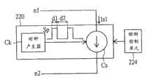
这里以两个例子说明负载仿真单元222所汲取的预定电流Is。在实际操作中,预定电流Is例如为固定(continuous)电流Is1或脉冲(pulse)电流Is2。而负载仿真单元222也可对应地予以设计。举例来说,请参照图3及图4,其分别绘示图2的产生固定电流与脉冲电流的负载仿真单元的一个示例的示意图。在此两个例子中,是以负载仿真单元222具有两端点n1及n2为例所绘示,且此两端点n1及n2是经由开关电路SW1分别连接至电源线L1与L2,用以接收电源信号Spw。Here, two examples are used to illustrate the predetermined current Is drawn by theload emulation unit 222 . In actual operation, the predetermined current Is is, for example, a constant (continuous) current Is1 or a pulse (pulse) current Is2 . Theload simulation unit 222 can also be designed accordingly. For example, please refer to FIG. 3 and FIG. 4 , which respectively show schematic diagrams of an example of the load emulation unit generating a fixed current and a pulse current in FIG. 2 . In these two examples, theload emulation unit 222 has two terminals n1 and n2 as an example, and the two terminals n1 and n2 are respectively connected to the power lines L1 and L2 through the switch circuit SW1 for receiving power Signal Spw.

在图3中,负载仿真单元222包括定电流电路Cs。定电流电路Cs用以汲取固定电流Is1。在实际操作中,定电流电路Cs例如为电流源电路,其在检测控制单元224的控制下所流经的电流实质上为固定电流Is1。In FIG. 3 , theload emulation unit 222 includes a constant current circuit Cs. The constant current circuit Cs is used to draw a fixed current Is1. In actual operation, the constant current circuit Cs is, for example, a current source circuit, and the current flowing through it under the control of thedetection control unit 224 is substantially the constant current Is1 .

在图4中,负载仿真单元222包括定电流电路Cs及时钟产生器Ck。时钟产生器Ck用以提供脉冲信号Sp来触发定电流电路Cs。由于受脉冲信号Sp触发的定电流电路Cs在检测控制单元224的控制下所流经的电流实质上为脉冲电流Is2。再者,此电流Is2具有以微秒(ms)为等级的脉冲宽度,例如是具有50微秒的脉冲宽度(如时段d1)。而电流Is2为低电平的时间(如时段d2)则例如为200微秒。In FIG. 4 , theload emulation unit 222 includes a constant current circuit Cs and a clock generator Ck. The clock generator Ck is used to provide the pulse signal Sp to trigger the constant current circuit Cs. The current flowing through the constant current circuit Cs triggered by the pulse signal Sp under the control of thedetection control unit 224 is substantially the pulse current Is2. Furthermore, the current Is2 has a pulse width in the order of microseconds (ms), for example, a pulse width of 50 microseconds (such as the period d1). The time during which the current Is2 is at a low level (such as the period d2 ) is, for example, 200 microseconds.

此外,请继续参照图2。在本实施例中,电源检测模块220可还包括开关电路SW1。开关电路SW1用以在检测控制单元224的控制下选择性地启动,而使负载仿真单元222经由连接开关电路SW1汲取预定电流Is。In addition, please continue to refer to FIG. 2 . In this embodiment, thepower detection module 220 may further include a switch circuit SW1. The switch circuit SW1 is used to selectively activate under the control of thedetection control unit 224 , so that theload emulation unit 222 draws a predetermined current Is through the connection switch circuit SW1 .

再者,在本实施例中,电源检测模块220还可包括开关电路SW2。开关电路SW2用以在检测控制单元224的控制下选择性地提供电源信号Spw至主功能装置210。详言之,若检测控制单元224判定电源信号Spw能驱动主功能装置210,则检测控制单元224连接开关电路SW2以提供电源信号Spw至主功能装置210。而若检测控制单元224判定电源信号Spw不能驱动主功能装置210,则检测控制单元224中断开关电路SW2而不提供电源信号Spw至主功能装置210。如此,通过控制此开关电路SW2,便能将电源信号Spw选择性地提供至主功能装置210。Furthermore, in this embodiment, thepower detection module 220 may further include a switch circuit SW2. The switch circuit SW2 is used for selectively providing the power signal Spw to themain function device 210 under the control of thedetection control unit 224 . In detail, if thedetection control unit 224 determines that the power signal Spw can drive themain function device 210 , thedetection control unit 224 connects the switch circuit SW2 to provide the power signal Spw to themain function device 210 . If thedetection control unit 224 determines that the power signal Spw cannot drive themain function device 210 , thedetection control unit 224 interrupts the switch circuit SW2 without providing the power signal Spw to themain function device 210 . In this way, by controlling the switch circuit SW2 , the power signal Spw can be selectively provided to themain function device 210 .

请同时参照图2与图5,图5绘示了图2的计算机外设设备200所应用的电源检测方法的详细流程图。此方法包括以下步骤。Please refer to FIG. 2 and FIG. 5 at the same time. FIG. 5 shows a detailed flowchart of the power detection method applied by the computerperipheral device 200 in FIG. 2 . This method includes the following steps.

在步骤S510中,接收数据通信接口BUS的电源信号Spw。举例来说,可由使用者先将电缆Cab1连接至信息处理装置300的连接端口Pot1,以使计算机外设设备200可经由数据通信接口BUS连接至信息处理装置300,而接收信息处理装置300所提供的电源信号Spw。之后,使用者可再视后续的情况来决定是否要连接电缆Cab2至信息处理装置300的连接端口Pot2。In step S510, a power signal Spw of the data communication interface BUS is received. For example, the user can first connect the cable Cab1 to the connection port Pot1 of theinformation processing device 300, so that the computerperipheral equipment 200 can be connected to theinformation processing device 300 through the data communication interface BUS, and receive the information provided by theinformation processing device 300. The power supply signal Spw. After that, the user can decide whether to connect the cable Cab2 to the connection port Pot2 of theinformation processing device 300 according to the subsequent situation.

接着,执行步骤S520,判断电源信号Spw是否能驱动主功能装置210。步骤S520包括步骤S522及步骤S524。详言之,在步骤S522中,检测控制单元224连接开关电路SW1,以使负载仿真单元222汲取对应电源信号Spw的预定电流Is。而在步骤S524中,检测控制单元224判断对应电源信号Spw的供应电压Vd是否小于预定电压。Next, step S520 is executed to determine whether the power signal Spw can drive themain function device 210 . Step S520 includes step S522 and step S524. In detail, in step S522 , thedetection control unit 224 connects the switch circuit SW1 so that theload emulation unit 222 draws a predetermined current Is corresponding to the power signal Spw. In step S524 , thedetection control unit 224 determines whether the supply voltage Vd corresponding to the power signal Spw is lower than a predetermined voltage.

若检测控制单元224判定供应电压Vd小于预定电压,则执行步骤S530。步骤S530包括步骤S532及步骤S534。在步骤S532中,检测控制单元224中断开关电路SW2而不将电源信号Spw提供至主功能装置210。在步骤S534中,检测控制单元224控制提示单元226提供第一提示信息(例如是呈现闪烁红灯),以提示使用者可将电缆Cab2连接至信息处理装置300。之后,回到步骤S520,以让计算机外设设备200继续判断电源信号Spw是否能驱动主功能装置210。If thedetection control unit 224 determines that the supply voltage Vd is lower than the predetermined voltage, step S530 is performed. Step S530 includes step S532 and step S534. In step S532 , thedetection control unit 224 interrupts the switch circuit SW2 without supplying the power signal Spw to themain function device 210 . In step S534 , thedetection control unit 224 controls theprompt unit 226 to provide first prompt information (for example, a flashing red light) to prompt the user to connect the cable Cab2 to theinformation processing device 300 . Afterwards, return to step S520 , so that the computerperipheral device 200 continues to determine whether the power signal Spw can drive themain function device 210 .

对应地,若检测控制单元224判定供应电压Vd大于预定电压,则执行步骤S540。步骤S540包括步骤S542、S544及S546。在步骤S542中,检测控制单元224中断开关电路SW1,以停止汲取预定电流Is。在步骤S544中,检测控制单元224连接开关SW2而将电源信号Spw提供至主功能装置210。在步骤S546中,检测控制单元224控制提示单元226提供第二信息(例如是呈现绿灯),以提示使用者此主功能装置210已可被正常使用。Correspondingly, if thedetection control unit 224 determines that the supply voltage Vd is greater than the predetermined voltage, step S540 is executed. Step S540 includes steps S542, S544 and S546. In step S542, thedetection control unit 224 interrupts the switch circuit SW1 to stop drawing the predetermined current Is. In step S544 , thedetection control unit 224 connects the switch SW2 to provide the power signal Spw to the mainfunctional device 210 . In step S546 , thedetection control unit 224 controls theprompt unit 226 to provide second information (for example, a green light) to remind the user that themain function device 210 is ready for normal use.

如图5所示,假设使用者在使用计算机外设设备200时,先连接电缆Cab1至信息处理装置300。此时,若计算机外设设备200的提示单元226提供上述的第一信息(如闪烁红灯),则使用者便可再连接电缆Cab2至信息处理装置300的其它位置的接口插座,以使计算机外设设备200可接收驱动能力较佳的电源信号Spw。如此,经计算机外设设备200判定电源信号Spw能驱动主功能装置210后,控制提示单元226提供第二信息(如呈现绿灯),以表示主功能装置210能正常运作并可供使用。As shown in FIG. 5 , assume that the user first connects the cable Cab1 to theinformation processing device 300 when using the computerperipheral device 200 . At this time, if theprompt unit 226 of the computerperipheral device 200 provides the above-mentioned first information (such as a flashing red light), the user can then connect the cable Cab2 to an interface socket at another position of theinformation processing device 300, so that the computer Theperipheral device 200 can receive the power signal Spw with better driving capability. In this way, after the computerperipheral device 200 determines that the power signal Spw can drive themain function device 210 , the controlprompt unit 226 provides second information (such as a green light) to indicate that themain function device 210 can operate normally and is available for use.

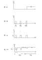
请参照图6A至图6D,其绘示了图2的计算机外设设备200的各种信号的波形图的一个示例。在此例中,预定电流Is的电平Ip设计为1.2安培,而预定电压的电平Vp则设计为4.3伏特。其中,图6A表示控制开关电路SW2的信号状态,图6B为控制开关电路SW1的信号状态,图6C为汲取对应电源信号Spw的预定电流Is的强度,图6D为对应电源信号Spw的供应电压Vd的强度。以下配合图5予以说明。Please refer to FIG. 6A to FIG. 6D , which illustrate an example of waveform diagrams of various signals of the computerperipheral device 200 in FIG. 2 . In this example, the level Ip of the predetermined current Is is designed to be 1.2 amperes, and the level Vp of the predetermined voltage is designed to be 4.3 volts. Among them, FIG. 6A shows the signal state of the control switch circuit SW2, FIG. 6B shows the signal state of the control switch circuit SW1, FIG. 6C shows the intensity of the predetermined current Is drawn corresponding to the power signal Spw, and FIG. 6D shows the supply voltage Vd corresponding to the power signal Spw. Strength of. It will be described below with reference to FIG. 5 .

首先,在进入步骤S510时,本实施例假设使用者先将电缆Cab1连接至信息处理装置300。接着,本实施例执行步骤S520以判断电源信号Spw是否能驱动主功能装置210。此时,检测控制单元224会将开关控制信号C1输入至开关电路SW1,如图6B中时段T11所示,而使开关电路SW1连接以汲取对应电源信号Spw的预定电流Is。同时,如图6D所示,供应电压Vd将会降低,且小于4.3伏特的预定电压Vp。因此,本实施例在时段T11后检测控制单元224并不会将开关控制信号C2输入至开关电路SW2,而使得开关电路SW2中断。之后,如时段T12所示,本实施例会再次执行步骤S520以再次判断电源信号Spw是否能驱动主功能装置210。换言之,本实施例会持续执行步骤S520直到系统判断电源信号Spw能够驱动主功能装置210,并且在此之前,开关电路SW2会被中断,故不会将电源信号Spw提供至主功能装置210。First, when entering step S510 , in this embodiment, it is assumed that the user firstly connects the cable Cab1 to theinformation processing device 300 . Next, the embodiment executes step S520 to determine whether the power signal Spw can drive themain function device 210 . At this time, thedetection control unit 224 will input the switch control signal C1 to the switch circuit SW1, as shown in the period T11 in FIG. 6B , so that the switch circuit SW1 is connected to draw a predetermined current Is corresponding to the power signal Spw. At the same time, as shown in FIG. 6D , the supply voltage Vd will decrease and be less than the predetermined voltage Vp of 4.3 volts. Therefore, in this embodiment, thedetection control unit 224 does not input the switch control signal C2 to the switch circuit SW2 after the time period T11 , so that the switch circuit SW2 is interrupted. Afterwards, as shown in the time period T12 , the embodiment executes step S520 again to determine whether the power signal Spw can drive themain function device 210 again. In other words, this embodiment will continue to execute step S520 until the system determines that the power signal Spw can drive themain function device 210 , and before that, the switch circuit SW2 will be interrupted, so the power signal Spw will not be provided to themain function device 210 .

接着,再假设使用者在时段T10之后,将电缆Cab2连接至信息处理装置300,在时段T21中,本实施例执行步骤S520以判断此时的电源信号Spw是否能驱动主功能装置210。同理,开关电路SW1会被连接。并且,如图6D所示,此时供应电压Vd将会降低,但此时会大于预定电压Vp,故在时段T21之后,本实施例将会检测控制单元224将输入开关控制信号C2至开关电路SW2以连接开关电路SW2,如图6A所示,而将电源信号Spw提供至主功能装置210。Next, assume that the user connects the cable Cab2 to theinformation processing device 300 after the time period T10. In the time period T21, the embodiment executes step S520 to determine whether the power signal Spw can drive themain function device 210 at this time. Similarly, the switch circuit SW1 will be connected. Moreover, as shown in FIG. 6D, the supply voltage Vd will decrease at this time, but it will be greater than the predetermined voltage Vp at this time, so after the period T21, this embodiment will detect that thecontrol unit 224 will input the switch control signal C2 to the switch circuit SW2 is connected to the switch circuit SW2 , as shown in FIG. 6A , to provide the power signal Spw to themain function device 210 .

进一步地,为了提高两条电缆Cab1与Cab2的辨识性并提高使用者的使用方便性,可设计使电缆Cab2的颜色异于电缆Cab1的颜色。如此,使用者在使用此计算机外设设备200时,便能清楚地分辨出具有不同内部线路的此两条电缆Cab1与Cab2。如此,使用者便可从颜色来判断出哪一条电缆为应先被使用的电缆(如电缆Cab1),从而提高使用者的使用方便性。Further, in order to improve the identification of the two cables Cab1 and Cab2 and improve the user's convenience, the color of the cable Cab2 can be designed to be different from the color of the cable Cab1. In this way, the user can clearly distinguish the two cables Cab1 and Cab2 with different internal circuits when using the computerperipheral device 200 . In this way, the user can judge from the color which cable should be used first (such as the cable Cab1 ), thereby improving the user's convenience.

再者,在另一实施例中,为了提高使用者的使用弹性,还可设计使电缆Cab2的长度大于电缆Cab1的长度。由于信息处理装置300(如笔记型计算机)从相邻的连接端口所提供的电源可能是由同一颗限流芯片(current limited IC)所控制,故此时即使将两条电缆Cab1及Cab2连接至相邻的两个连接端口Pot1及Pot2时,也无法取得具备足够驱动能力的电源信号。而在本实施例中,设计使电缆Cab2具有较长的长度。如此,当使用者以电缆Cab1连接计算机外设设备200至一个连接端口时,还能以此较长的电缆Cab2来连接计算机外设设备200至距离较远且对应至另一颗限流芯片的另一个连接端口,由此取得驱动能力较佳的电源信号。故知,本实施例并不受限于只能将计算机外设设备200连接至相邻的两个连接端口,而具有较佳的使用弹性。Moreover, in another embodiment, in order to improve the flexibility of the user, the length of the cable Cab2 can also be designed to be greater than the length of the cable Cab1. Since the power provided by the information processing device 300 (such as a notebook computer) from adjacent connection ports may be controlled by the same current limited IC, even if the two cables Cab1 and Cab2 are connected to the corresponding When the two adjacent connection ports Pot1 and Pot2 are connected, a power signal with sufficient driving capability cannot be obtained. In this embodiment, however, the cable Cab2 is designed to have a relatively long length. In this way, when the user uses the cable Cab1 to connect the computerperipheral device 200 to a connection port, the longer cable Cab2 can also be used to connect the computerperipheral device 200 to a remote port corresponding to another current limiting chip. Another connection port to obtain a power signal with better drive capability. Therefore, this embodiment is not limited to only connecting the computerperipheral device 200 to two adjacent connection ports, but has better usage flexibility.

本发明上述实施例所描述的电源检测模块及其计算机外设设备与其所应用的电源检测方法,通过判断数据通信接口的电源信号是否足以驱动主功能装置的主功能装置,并依据判断结果选择性地提供电源信号给主功能装置以驱动主功能装置的运作。如此,数据通信接口的电源信号得以正确及有效的运用于不同电源规格的外围设备,尤其是外接式储存装置,并能避免其中的主功能装置因为电源信号不稳而影响其动作。如此,使用者在电源可靠的情况下可正常及方便的使用主功能装置,能避免在未明状况下直接利用电源信号时可能造成的不可预期的数据损失或影响整体系统运作的情况。The power detection module described in the above-mentioned embodiments of the present invention, its computer peripheral equipment and the power detection method applied thereto, determine whether the power signal of the data communication interface is sufficient to drive the main function device of the main function device, and select according to the judgment result The ground provides a power signal to the main function device to drive the operation of the main function device. In this way, the power signal of the data communication interface can be correctly and effectively applied to peripheral devices with different power specifications, especially the external storage device, and can prevent the operation of the main function device from being affected by the unstable power signal. In this way, the user can normally and conveniently use the main function device when the power supply is reliable, and can avoid unexpected data loss or influence on the overall system operation that may be caused when the power signal is directly used under unknown conditions.

综上所述,虽然本发明已以较佳实施例描述如上,但其并非用以限定本发明。本发明所属技术领域中的技术人员,在不脱离本发明的精神和范围内,可作各种的更动与润饰。因此,本发明的保护范围应以后附的权利要求所界定的范围为准。In summary, although the present invention has been described above with preferred embodiments, it is not intended to limit the present invention. Those skilled in the art to which the present invention belongs can make various changes and modifications without departing from the spirit and scope of the present invention. Therefore, the scope of protection of the present invention shall prevail as defined by the appended claims.

Claims (29)

Translated fromChinese
1.一种电源检测方法,适用于计算机外设设备,该方法包括:1. A power detection method, suitable for computer peripheral equipment, the method comprising:接收数据通信接口的电源信号;Receive the power signal of the data communication interface;汲取对应至该电源信号的预定电流;以及drawing a predetermined current corresponding to the power supply signal; and判断对应至该电源信号的供应电压是否小于预定电压;judging whether the supply voltage corresponding to the power supply signal is less than a predetermined voltage;若判定该供应电压小于该预定电压,则不提供该电源信号至主功能装置;以及If it is determined that the supply voltage is less than the predetermined voltage, the power supply signal is not provided to the main function device; and若判定该供应电压大于该预定电压,提供该电源信号至该主功能装置。If it is determined that the supply voltage is greater than the predetermined voltage, the power signal is provided to the main function device.2.如权利要求1所述的电源检测方法,2. the power detection method as claimed in claim 1,其中,该方法在判定该供应电压小于该预定电压之后,还包括:Wherein, after determining that the supply voltage is less than the predetermined voltage, the method further includes:继续执行判断该电源信号是否能驱动该主功能装置的该步骤。Continue to execute the step of judging whether the power signal can drive the main function device.3.如权利要求1所述的电源检测方法,其中,该方法在判定该供应电压大于该预定电压之后,还包括:3. The power detection method according to claim 1, wherein, after determining that the supply voltage is greater than the predetermined voltage, the method further comprises:停止汲取该预定电流。Stop drawing the predetermined current.4.如权利要求1所述的电源检测方法,其中该预定电流为固定电流。4. The power detection method as claimed in claim 1, wherein the predetermined current is a fixed current.5.如权利要求1所述的电源检测方法,其中该预定电流为脉冲电流5. The power detection method as claimed in claim 1, wherein the predetermined current is a pulse current6.如权利要求1所述的电源检测方法,还包括:6. The power detection method according to claim 1, further comprising:依据该判断结果提供对应的提示信息。Corresponding prompt information is provided according to the determination result.7.如权利要求1所述的电源检测方法,其中该数据通信接口为符合基于通用串行总线协议的接口。7. The power detection method as claimed in claim 1, wherein the data communication interface is an interface based on a universal serial bus protocol.8.一种计算机外设设备,包括:8. A computer peripheral device, comprising:主功能装置;以及main function device; and电源检测模块,用以接收数据通信接口的电源信号,The power detection module is used to receive the power signal of the data communication interface,其中该电源检测模块包括:Wherein the power detection module includes:负载仿真单元,用以汲取对应至该电源信号的预定电流;以及a load emulation unit for drawing a predetermined current corresponding to the power signal; and检测控制单元,用以判断对应至该电源信号的供应电压是否小于预定电压;A detection control unit, used to determine whether the supply voltage corresponding to the power signal is less than a predetermined voltage;其中,若该检测控制单元判定该供应电压小于该预定电压,则该检测控制单元不提供该电源信号至该主功能装置,并继续进行判断该电源信号是否能驱动该主功能装置的动作;Wherein, if the detection control unit determines that the supply voltage is lower than the predetermined voltage, the detection control unit does not provide the power signal to the main functional device, and continues to judge whether the power signal can drive the main functional device;其中,若该检测控制单元判定该供应电压大于该预定电压,则该检测控制单元提供该电源信号至该主功能装置,并停止汲取该预定电流。Wherein, if the detection control unit determines that the supply voltage is greater than the predetermined voltage, the detection control unit provides the power signal to the main functional device and stops drawing the predetermined current.9.如权利要求8所述的计算机外设设备,其中该电源检测模块还包括:9. The computer peripheral device as claimed in claim 8, wherein the power detection module further comprises:第二开关电路,在该电源检测模块的控制下选择性地提供该电源信号至该主功能装置;a second switch circuit selectively provides the power signal to the main function device under the control of the power detection module;其中,若该电源检测模块判定该电源信号能驱动该主功能装置,则该电源检测模块连接该第二开关电路以提供该电源信号至该主功能装置,而若该电源检测模块判定该电源信号不能驱动该主功能装置,则该电源检测模块中断该第二开关电路而不提供该电源信号至该主功能装置。Wherein, if the power detection module determines that the power signal can drive the main function device, the power detection module connects the second switch circuit to provide the power signal to the main function device, and if the power detection module determines that the power signal If the main function device cannot be driven, the power detection module interrupts the second switch circuit without providing the power signal to the main function device.10.如权利要求8所述的计算机外设设备,其中该电源检测模块还包括:10. The computer peripheral device as claimed in claim 8, wherein the power detection module further comprises:第一开关电路,用以在该检测控制单元的控制下选择性地启动,而使该负载仿真单元经由连接该第一开关电路汲取该预定电流。The first switch circuit is used for selectively starting under the control of the detection control unit, so that the load emulation unit draws the predetermined current through the connection with the first switch circuit.11.如权利要求8所述的计算机外设设备,其中该预定电流为固定电流。11. The computer peripheral device as claimed in claim 8, wherein the predetermined current is a fixed current.12.如权利要求11所述的计算机外设设备,其中该负载仿真单元包括:12. The computer peripheral device as claimed in claim 11, wherein the load emulation unit comprises:定电流电路,用以汲取该固定电流。The constant current circuit is used to draw the fixed current.13.如权利要求8所述的计算机外设设备,其中该预定电流为脉冲电流。13. The computer peripheral device as claimed in claim 8, wherein the predetermined current is a pulse current.14.如权利要求13所述的计算机外设设备,其中该负载仿真单元包括:14. The computer peripheral device as claimed in claim 13, wherein the load emulation unit comprises:定电流电路;以及constant current circuit; and时钟产生器,用以提供脉冲信号来触发该定电流电路,以使该定电流电路汲取该脉冲电流。The clock generator is used to provide a pulse signal to trigger the constant current circuit, so that the constant current circuit draws the pulse current.15.如权利要求8所述的计算机外设设备,其中该电源检测模块还包括:15. The computer peripheral device as claimed in claim 8, wherein the power detection module further comprises:提示单元,用以在该检测控制单元的控制下提供对应的提示信息。A prompting unit, configured to provide corresponding prompting information under the control of the detection control unit.16.如权利要求8所述的计算机外设设备,还包括:16. The computer peripheral device of claim 8, further comprising:至少一电缆,设有该数据通信接口在其中,该至少一电缆的一端整合于该计算机外设设备之中。At least one cable is provided with the data communication interface, and one end of the at least one cable is integrated in the computer peripheral equipment.17.如权利要求16所述的计算机外设设备,其中该至少一电缆包括第一电缆及第二电缆,该第一电缆具有一对第一电源线及一对信号线,该第二电缆具有一对第二电源线,该两对电源线并联连接。17. The computer peripheral device as claimed in claim 16, wherein the at least one cable comprises a first cable and a second cable, the first cable has a pair of first power lines and a pair of signal lines, and the second cable has A pair of second power lines, the two pairs of power lines are connected in parallel.18.如权利要求17所述的计算机外设设备,其中该第二电缆的长度大于该第一电缆的长度。18. The computer peripheral device as claimed in claim 17, wherein the length of the second cable is greater than the length of the first cable.19.如权利要求17所述的计算机外设设备,其中该第二电缆的颜色异于该第一电缆的颜色。19. The computer peripheral device of claim 17, wherein the color of the second cable is different from the color of the first cable.20.如权利要求8所述的计算机外设设备,其中该数据通信接口为符合基于通用串行总线协议的接口。20. The computer peripheral device as claimed in claim 8, wherein the data communication interface is an interface based on a Universal Serial Bus protocol.21.如权利要求8所述的计算机外设设备,其中该主功能装置适用于外接式光驱或外接式硬盘。21. The computer peripheral device as claimed in claim 8, wherein the main function device is suitable for an external optical drive or an external hard disk.22.一种电源检测模块,适用于计算机外设设备中,该电源检测模块包括:22. A power detection module, suitable for computer peripheral equipment, the power detection module includes:负载仿真单元,用以汲取对应至数据通信接口的电源信号的预定电流;以及a load emulation unit for drawing a predetermined current corresponding to a power signal of the data communication interface; and检测控制单元,用以控制该负载仿真单元汲取该预定电流,并判断对应至该电源信号的供应电压是否小于预定电压,由此判断该电源信号是否能驱动该计算机外设设备的主功能装置,其中,若该检测控制单元判定该供应电压小于该预定电压,则该检测控制单元判定该电源信号不能驱动该主功能装置而不提供该电源信号给该主功能装置,其中,若该检测控制单元判定该供应电压大于该预定电压,则该检测控制单元判定该电源信号能驱动该主功能装置且提供该电源信号至该主功能装置,并停止汲取该预定电流。The detection control unit is used to control the load simulation unit to draw the predetermined current, and judge whether the supply voltage corresponding to the power signal is less than the predetermined voltage, thereby judging whether the power signal can drive the main functional device of the computer peripheral device, Wherein, if the detection control unit determines that the supply voltage is lower than the predetermined voltage, the detection control unit determines that the power signal cannot drive the main function device and does not provide the power signal to the main function device, wherein, if the detection control unit When it is determined that the supply voltage is greater than the predetermined voltage, the detection control unit determines that the power signal can drive the main function device and provides the power signal to the main function device, and stops drawing the predetermined current.23.如权利要求22所述的电源检测模块,还包括:23. The power detection module of claim 22, further comprising:第二开关电路,用以在该检测控制单元的控制下选择性地提供该电源信号至该主功能装置;a second switch circuit for selectively providing the power signal to the main function device under the control of the detection control unit;其中,若该检测控制单元判定该电源信号能驱动该主功能装置,则该检测控制单元连接该第二开关电路以提供该电源信号至该主功能装置,而若该检测控制单元判定该电源信号不能驱动该主功能装置,则该检测控制单元中断该第二开关电路而不提供该电源信号至该主功能装置。Wherein, if the detection control unit determines that the power signal can drive the main function device, the detection control unit connects the second switch circuit to provide the power signal to the main function device, and if the detection control unit determines that the power signal If the main functional device cannot be driven, the detection control unit interrupts the second switch circuit without providing the power signal to the main functional device.24.如权利要求22所述的电源检测模块,还包括:24. The power detection module of claim 22, further comprising:第一开关电路,用以在该检测控制单元的控制下选择性地启动,而使该负载仿真单元经由连接该第一开关电路汲取该预定电流。The first switch circuit is used for selectively starting under the control of the detection control unit, so that the load emulation unit draws the predetermined current through the connection with the first switch circuit.25.如权利要求22所述的电源检测模块,其中该预定电流为固定电流。25. The power detection module as claimed in claim 22, wherein the predetermined current is a fixed current.26.如权利要求25所述的电源检测模块,其中该负载仿真单元包括:26. The power detection module as claimed in claim 25, wherein the load emulation unit comprises:定电流电路,用以汲取该固定电流。The constant current circuit is used to draw the fixed current.27.如权利要求22所述的电源检测模块,其中该预定电流为脉冲电流。27. The power detection module as claimed in claim 22, wherein the predetermined current is a pulse current.28.如权利要求27所述的电源检测模块,其中该负载仿真单元包括:28. The power detection module as claimed in claim 27, wherein the load emulation unit comprises:定电流电路;以及constant current circuit; and时钟产生器,用以提供脉冲信号来触发该定电流电路,以使该定电流电路汲取该脉冲电流。The clock generator is used to provide a pulse signal to trigger the constant current circuit, so that the constant current circuit draws the pulse current.29.如权利要求22所述的电源检测模块,还包括:29. The power detection module of claim 22, further comprising:提示单元,用以在该检测控制单元的控制下提供对应的提示信息。A prompting unit, configured to provide corresponding prompting information under the control of the detection control unit.
CN2009101338423A2009-04-032009-04-03 Power supply detection module and its computer peripheral equipment and its power supply detection methodExpired - Fee RelatedCN101853060B (en)

Priority Applications (2)

Application NumberPriority DateFiling DateTitle
CN2009101338423ACN101853060B (en)2009-04-032009-04-03 Power supply detection module and its computer peripheral equipment and its power supply detection method
US12/554,267US8205108B2 (en)2009-04-032009-09-04Method and module for power detection and peripheral apparatus using the same

Applications Claiming Priority (1)

Application NumberPriority DateFiling DateTitle
CN2009101338423ACN101853060B (en)2009-04-032009-04-03 Power supply detection module and its computer peripheral equipment and its power supply detection method

Publications (2)

Publication NumberPublication Date
CN101853060A CN101853060A (en)2010-10-06
CN101853060Btrue CN101853060B (en)2012-04-18

Family

ID=42804588

Family Applications (1)

Application NumberTitlePriority DateFiling Date
CN2009101338423AExpired - Fee RelatedCN101853060B (en)2009-04-032009-04-03 Power supply detection module and its computer peripheral equipment and its power supply detection method

Country Status (2)

CountryLink
US (1)US8205108B2 (en)
CN (1)CN101853060B (en)

Families Citing this family (3)

* Cited by examiner, † Cited by third party
Publication numberPriority datePublication dateAssigneeTitle
TW201126332A (en)*2010-01-262011-08-01Transcend Information IncExternal device having low power detection and protection and method thereof
US20140201544A1 (en)*2013-01-142014-07-17Chen Hsi TAIExternal storage device and driving method thereof
CN115483673A (en)*2022-09-232022-12-16重庆鼎石国际贸易有限公司Multifunctional power supply device control system

Citations (3)

* Cited by examiner, † Cited by third party
Publication numberPriority datePublication dateAssigneeTitle
CN1619466A (en)*2003-11-202005-05-25英业达股份有限公司 Power supply monitoring and management method for detecting single uninterruptible power supply system and multiple servers
US6901524B2 (en)*1989-10-302005-05-31Texas Instruments IncorporatedProcessor having real-time power conservation and thermal management
CN1853153A (en)*2003-09-302006-10-25英特尔公司 Toggles the display of update properties when a power management event is detected

Family Cites Families (5)

* Cited by examiner, † Cited by third party
Publication numberPriority datePublication dateAssigneeTitle
US20060047880A1 (en)*2004-08-272006-03-02Imation Corp.Memory device with HUB capability
TW200723632A (en)*2005-12-152007-06-16Inventec CorpCurrent overload status-informing system and the method
US7463469B2 (en)*2006-02-022008-12-09Texas Instruments IncorporatedSystem and method for current overload response with class D topology
US7996698B2 (en)*2007-04-052011-08-09Aruba Networks, Inc.System and method for enabling functionality based on measured power
US8321706B2 (en)*2007-07-232012-11-27Marvell World Trade Ltd.USB self-idling techniques

Patent Citations (3)

* Cited by examiner, † Cited by third party
Publication numberPriority datePublication dateAssigneeTitle
US6901524B2 (en)*1989-10-302005-05-31Texas Instruments IncorporatedProcessor having real-time power conservation and thermal management
CN1853153A (en)*2003-09-302006-10-25英特尔公司 Toggles the display of update properties when a power management event is detected
CN1619466A (en)*2003-11-202005-05-25英业达股份有限公司 Power supply monitoring and management method for detecting single uninterruptible power supply system and multiple servers

Also Published As

Publication numberPublication date
CN101853060A (en)2010-10-06
US20100257395A1 (en)2010-10-07
US8205108B2 (en)2012-06-19

Similar Documents

PublicationPublication DateTitle
US9104396B2 (en)Electronic apparatus, charging control device, and charging control method
US20100060233A1 (en)Charger with USB detection
US20150143138A1 (en)System for detecting universal serial bus (usb) device and method thereof
US20110320837A1 (en)Power supply circuit, power supply method, and signal processing apparatus
CN106786960B (en) Charging control method, device and terminal
JP2018032221A (en)Electronic device and control method of the same
US20090199222A1 (en)Optical Disc Drive
CN105677596B (en)Control method and electronic equipment
CN101853060B (en) Power supply detection module and its computer peripheral equipment and its power supply detection method
US20140157012A1 (en)Information processing apparatus and power supplying method
US9331492B2 (en)Detection control device and method thereof
US20190051358A1 (en)Chip programming device and protecting method thereof
US20110181432A1 (en)External device having low power detection and protection and method thereof
CN112015688A (en) A hot-swap auxiliary circuit
TWI451235B (en)Connecting module for coupling output ends of a host device to an external storage device and coupling method thereof
JP2023040804A (en)Port controller and electronic apparatus
KR101237424B1 (en)Computer comprising non-limited current USB connector
CN101436425B (en)Circuit for controlling power supply of functional module and wireless data terminal equipment
US6766392B2 (en)Electronic apparatus, control circuit for electronic apparatus, and method of controlling electronic apparatus
KR100700532B1 (en) How to recognize the connector on the universal serial bus port and the universal serial bus adapter
JP2018169676A (en) Electronic device and power supply method for electronic device
JP6916629B2 (en) Electronics and control methods
US20160147701A1 (en)Bridge for bus-powered peripheral device power management
TWI829240B (en)Electronic device
US11432384B2 (en)LED control for reversable power cable

Legal Events

DateCodeTitleDescription
C06Publication
PB01Publication
C10Entry into substantive examination
SE01Entry into force of request for substantive examination
C14Grant of patent or utility model
GR01Patent grant
C17Cessation of patent right
CF01Termination of patent right due to non-payment of annual fee

Granted publication date:20120418

Termination date:20140403


[8]ページ先頭

©2009-2025 Movatter.jp