CN101852810B - Sample analyzer and assembly thereof - Google Patents
Sample analyzer and assembly thereofDownload PDFInfo
- Publication number
- CN101852810B CN101852810BCN200910258685.9ACN200910258685ACN101852810BCN 101852810 BCN101852810 BCN 101852810BCN 200910258685 ACN200910258685 ACN 200910258685ACN 101852810 BCN101852810 BCN 101852810B
- Authority
- CN
- China
- Prior art keywords
- sample
- pipette
- syringe pump
- container
- diluent
- Prior art date
- Legal status (The legal status is an assumption and is not a legal conclusion. Google has not performed a legal analysis and makes no representation as to the accuracy of the status listed.)
- Expired - Fee Related
Links
- 238000004458analytical methodMethods0.000claimsabstractdescription43
- 238000002360preparation methodMethods0.000claimsabstractdescription17
- 239000000523sampleSubstances0.000claimsdescription277
- 239000000538analytical sampleSubstances0.000claimsdescription3
- 239000007788liquidSubstances0.000description124
- 239000003085diluting agentSubstances0.000description91
- 210000004369bloodAnatomy0.000description85
- 239000008280bloodSubstances0.000description85
- 239000003795chemical substances by applicationSubstances0.000description39
- 230000002949hemolytic effectEffects0.000description38
- 238000004140cleaningMethods0.000description37
- 239000012530fluidSubstances0.000description34
- 238000002156mixingMethods0.000description34
- 239000002699waste materialSubstances0.000description29
- 238000010586diagramMethods0.000description28
- 238000001514detection methodMethods0.000description25
- 238000005259measurementMethods0.000description25
- 210000003743erythrocyteAnatomy0.000description22
- 229920001971elastomerPolymers0.000description21
- 210000000265leukocyteAnatomy0.000description21
- 102000001554HemoglobinsHuman genes0.000description20
- 108010054147HemoglobinsProteins0.000description20
- 238000006243chemical reactionMethods0.000description10
- 210000001772blood plateletAnatomy0.000description9
- 238000010790dilutionMethods0.000description9
- 239000012895dilutionSubstances0.000description9
- 238000005534hematocritMethods0.000description9
- 239000003219hemolytic agentSubstances0.000description9
- 239000000306componentSubstances0.000description8
- 239000012470diluted sampleSubstances0.000description8
- 238000000034methodMethods0.000description8
- 238000012545processingMethods0.000description8
- 238000010241blood samplingMethods0.000description7
- 238000003780insertionMethods0.000description7
- 230000037431insertionEffects0.000description7
- 239000004973liquid crystal related substanceSubstances0.000description7
- 230000004308accommodationEffects0.000description6
- 238000004891communicationMethods0.000description6
- 239000010935stainless steelSubstances0.000description6
- 229910001220stainless steelInorganic materials0.000description6
- 229920000122acrylonitrile butadiene styrenePolymers0.000description5
- 230000008859changeEffects0.000description5
- 238000012423maintenanceMethods0.000description5
- 238000012546transferMethods0.000description5
- 238000004159blood analysisMethods0.000description4
- 230000006835compressionEffects0.000description4
- 238000007906compressionMethods0.000description4
- 238000001816coolingMethods0.000description4
- 238000007599dischargingMethods0.000description4
- 238000005192partitionMethods0.000description4
- 230000002093peripheral effectEffects0.000description4
- 230000007704transitionEffects0.000description4
- 239000012503blood componentSubstances0.000description3
- 238000007865dilutingMethods0.000description3
- 238000007689inspectionMethods0.000description3
- 238000007639printingMethods0.000description3
- 230000009467reductionEffects0.000description3
- 229920005989resinPolymers0.000description3
- 239000011347resinSubstances0.000description3
- 238000003860storageMethods0.000description3
- 239000011800void materialSubstances0.000description3
- 238000002835absorbanceMethods0.000description2
- XECAHXYUAAWDEL-UHFFFAOYSA-Nacrylonitrile butadiene styreneChemical compoundC=CC=C.C=CC#N.C=CC1=CC=CC=C1XECAHXYUAAWDEL-UHFFFAOYSA-N0.000description2
- 239000004676acrylonitrile butadiene styreneSubstances0.000description2
- 238000002347injectionMethods0.000description2
- 239000007924injectionSubstances0.000description2
- 239000000203mixtureSubstances0.000description2
- BASFCYQUMIYNBI-UHFFFAOYSA-NplatinumChemical compound[Pt]BASFCYQUMIYNBI-UHFFFAOYSA-N0.000description2
- 230000008569processEffects0.000description2
- 238000011002quantificationMethods0.000description2
- 125000006850spacer groupChemical group0.000description2
- 210000002700urineAnatomy0.000description2
- 229910000838Al alloyInorganic materials0.000description1
- 241000124008MammaliaSpecies0.000description1
- 241001465754MetazoaSpecies0.000description1
- 229920002614Polyether block amidePolymers0.000description1
- 239000004697PolyetherimideSubstances0.000description1
- 229910000831SteelInorganic materials0.000description1
- 230000002411adverseEffects0.000description1
- 238000013019agitationMethods0.000description1
- 239000003153chemical reaction reagentSubstances0.000description1
- 238000005253claddingMethods0.000description1
- 239000011248coating agentSubstances0.000description1
- 238000000576coating methodMethods0.000description1
- 238000004737colorimetric analysisMethods0.000description1
- 238000010276constructionMethods0.000description1
- 230000004069differentiationEffects0.000description1
- 238000009826distributionMethods0.000description1
- 230000014509gene expressionEffects0.000description1
- 230000020169heat generationEffects0.000description1
- 238000004519manufacturing processMethods0.000description1
- 238000012986modificationMethods0.000description1
- 230000004048modificationEffects0.000description1
- 230000003287optical effectEffects0.000description1
- 230000000149penetrating effectEffects0.000description1
- 229910052697platinumInorganic materials0.000description1
- 229920002492poly(sulfone)Polymers0.000description1
- 229920001601polyetherimidePolymers0.000description1
- 239000010979rubySubstances0.000description1
- 229910001750rubyInorganic materials0.000description1
- 238000005070samplingMethods0.000description1
- 238000007789sealingMethods0.000description1
- 229920002379silicone rubberPolymers0.000description1
- 238000005549size reductionMethods0.000description1
- 239000000243solutionSubstances0.000description1
- 239000007921spraySubstances0.000description1
- 230000003068static effectEffects0.000description1
- 239000010959steelSubstances0.000description1
- 230000003746surface roughnessEffects0.000description1
- 230000001360synchronised effectEffects0.000description1
- 238000012360testing methodMethods0.000description1
- 229920005992thermoplastic resinPolymers0.000description1
Images


Classifications
- G—PHYSICS
- G01—MEASURING; TESTING
- G01N—INVESTIGATING OR ANALYSING MATERIALS BY DETERMINING THEIR CHEMICAL OR PHYSICAL PROPERTIES
- G01N35/00—Automatic analysis not limited to methods or materials provided for in any single one of groups G01N1/00 - G01N33/00; Handling materials therefor
- G01N35/10—Devices for transferring samples or any liquids to, in, or from, the analysis apparatus, e.g. suction devices, injection devices
- G01N35/1009—Characterised by arrangements for controlling the aspiration or dispense of liquids
- G01N35/1016—Control of the volume dispensed or introduced
- B—PERFORMING OPERATIONS; TRANSPORTING
- B01—PHYSICAL OR CHEMICAL PROCESSES OR APPARATUS IN GENERAL
- B01L—CHEMICAL OR PHYSICAL LABORATORY APPARATUS FOR GENERAL USE
- B01L9/00—Supporting devices; Holding devices
- B01L9/06—Test-tube stands; Test-tube holders
- G—PHYSICS
- G01—MEASURING; TESTING
- G01N—INVESTIGATING OR ANALYSING MATERIALS BY DETERMINING THEIR CHEMICAL OR PHYSICAL PROPERTIES
- G01N15/00—Investigating characteristics of particles; Investigating permeability, pore-volume or surface-area of porous materials
- G01N15/10—Investigating individual particles
- G01N15/1031—Investigating individual particles by measuring electrical or magnetic effects
- G01N15/12—Investigating individual particles by measuring electrical or magnetic effects by observing changes in resistance or impedance across apertures when traversed by individual particles, e.g. by using the Coulter principle
- G01N15/13—Details pertaining to apertures
- G—PHYSICS
- G01—MEASURING; TESTING
- G01N—INVESTIGATING OR ANALYSING MATERIALS BY DETERMINING THEIR CHEMICAL OR PHYSICAL PROPERTIES
- G01N35/00—Automatic analysis not limited to methods or materials provided for in any single one of groups G01N1/00 - G01N33/00; Handling materials therefor
- G01N35/10—Devices for transferring samples or any liquids to, in, or from, the analysis apparatus, e.g. suction devices, injection devices
- G01N35/1079—Devices for transferring samples or any liquids to, in, or from, the analysis apparatus, e.g. suction devices, injection devices with means for piercing stoppers or septums
- B—PERFORMING OPERATIONS; TRANSPORTING
- B01—PHYSICAL OR CHEMICAL PROCESSES OR APPARATUS IN GENERAL
- B01L—CHEMICAL OR PHYSICAL LABORATORY APPARATUS FOR GENERAL USE
- B01L2200/00—Solutions for specific problems relating to chemical or physical laboratory apparatus
- B01L2200/14—Process control and prevention of errors
- B01L2200/143—Quality control, feedback systems
- B—PERFORMING OPERATIONS; TRANSPORTING
- B01—PHYSICAL OR CHEMICAL PROCESSES OR APPARATUS IN GENERAL
- B01L—CHEMICAL OR PHYSICAL LABORATORY APPARATUS FOR GENERAL USE
- B01L3/00—Containers or dishes for laboratory use, e.g. laboratory glassware; Droppers
- B01L3/02—Burettes; Pipettes
- G—PHYSICS
- G01—MEASURING; TESTING
- G01N—INVESTIGATING OR ANALYSING MATERIALS BY DETERMINING THEIR CHEMICAL OR PHYSICAL PROPERTIES
- G01N15/00—Investigating characteristics of particles; Investigating permeability, pore-volume or surface-area of porous materials
- G01N15/01—Investigating characteristics of particles; Investigating permeability, pore-volume or surface-area of porous materials specially adapted for biological cells, e.g. blood cells
- G01N2015/012—Red blood cells
- G—PHYSICS
- G01—MEASURING; TESTING
- G01N—INVESTIGATING OR ANALYSING MATERIALS BY DETERMINING THEIR CHEMICAL OR PHYSICAL PROPERTIES
- G01N15/00—Investigating characteristics of particles; Investigating permeability, pore-volume or surface-area of porous materials
- G01N15/01—Investigating characteristics of particles; Investigating permeability, pore-volume or surface-area of porous materials specially adapted for biological cells, e.g. blood cells
- G01N2015/016—White blood cells
- G—PHYSICS
- G01—MEASURING; TESTING
- G01N—INVESTIGATING OR ANALYSING MATERIALS BY DETERMINING THEIR CHEMICAL OR PHYSICAL PROPERTIES
- G01N15/00—Investigating characteristics of particles; Investigating permeability, pore-volume or surface-area of porous materials
- G01N15/01—Investigating characteristics of particles; Investigating permeability, pore-volume or surface-area of porous materials specially adapted for biological cells, e.g. blood cells
- G01N2015/018—Platelets
- G—PHYSICS
- G01—MEASURING; TESTING
- G01N—INVESTIGATING OR ANALYSING MATERIALS BY DETERMINING THEIR CHEMICAL OR PHYSICAL PROPERTIES
- G01N15/00—Investigating characteristics of particles; Investigating permeability, pore-volume or surface-area of porous materials
- G01N15/10—Investigating individual particles
- G01N2015/1024—Counting particles by non-optical means
- G—PHYSICS
- G01—MEASURING; TESTING
- G01N—INVESTIGATING OR ANALYSING MATERIALS BY DETERMINING THEIR CHEMICAL OR PHYSICAL PROPERTIES
- G01N35/00—Automatic analysis not limited to methods or materials provided for in any single one of groups G01N1/00 - G01N33/00; Handling materials therefor
- G01N35/10—Devices for transferring samples or any liquids to, in, or from, the analysis apparatus, e.g. suction devices, injection devices
- G01N35/1009—Characterised by arrangements for controlling the aspiration or dispense of liquids
- G01N35/1016—Control of the volume dispensed or introduced
- G01N2035/1018—Detecting inhomogeneities, e.g. foam, bubbles, clots
- G—PHYSICS
- G01—MEASURING; TESTING
- G01N—INVESTIGATING OR ANALYSING MATERIALS BY DETERMINING THEIR CHEMICAL OR PHYSICAL PROPERTIES
- G01N35/00—Automatic analysis not limited to methods or materials provided for in any single one of groups G01N1/00 - G01N33/00; Handling materials therefor
- G01N35/10—Devices for transferring samples or any liquids to, in, or from, the analysis apparatus, e.g. suction devices, injection devices
- G01N2035/1027—General features of the devices
- G01N2035/1032—Dilution or aliquotting
- G—PHYSICS
- G01—MEASURING; TESTING
- G01N—INVESTIGATING OR ANALYSING MATERIALS BY DETERMINING THEIR CHEMICAL OR PHYSICAL PROPERTIES
- G01N35/00—Automatic analysis not limited to methods or materials provided for in any single one of groups G01N1/00 - G01N33/00; Handling materials therefor
- G01N35/10—Devices for transferring samples or any liquids to, in, or from, the analysis apparatus, e.g. suction devices, injection devices
- G01N35/1004—Cleaning sample transfer devices
Landscapes
- Chemical & Material Sciences (AREA)
- Health & Medical Sciences (AREA)
- Immunology (AREA)
- Pathology (AREA)
- Analytical Chemistry (AREA)
- Biochemistry (AREA)
- General Health & Medical Sciences (AREA)
- General Physics & Mathematics (AREA)
- Physics & Mathematics (AREA)
- Life Sciences & Earth Sciences (AREA)
- Clinical Laboratory Science (AREA)
- Chemical Kinetics & Catalysis (AREA)
- Dispersion Chemistry (AREA)
- Automatic Analysis And Handling Materials Therefor (AREA)
- Sampling And Sample Adjustment (AREA)
- Investigating Or Analysing Biological Materials (AREA)
Abstract
Description
Translated fromChinese本申请是发明名称为“试样分析器及其组件”的中国专利申请200610095803.5的分案申请。现依据专利局于2009年9月18日发出的《分案通知书》,提交本分案申请。This application is a divisional application of the Chinese patent application 200610095803.5 with the invention title "sample analyzer and its components". This divisional application is now submitted in accordance with the "Notice of Divisional Application" issued by the Patent Office on September 18, 2009.
技术领域technical field
本发明涉及一种用于分析血液试样和尿样等的试样分析器及其使用的组件,本发明尤其涉及一种多用途的便携式试样分析器。The present invention relates to a sample analyzer for analyzing blood samples, urine samples, etc. and components used therefor, and in particular, the present invention relates to a multi-purpose portable sample analyzer.
背景技术Background technique
迄今已知的和本发明有关的技术如下。Hitherto known techniques related to the present invention are as follows.
一种小型的自动分析器,其包括圆周部分等距离的分成多个部分的具有反应台的反应容器盘;由该反应容器盘保持的多个反应容器、用于将各反应容器传送到试样分析器、试剂分配位置和光学测量位置的装置;用于吸取和分配所要求量的试样到反应容器的装置,以及用于在反应容器中光学分析试样的装置(例如,在日本未审查的专利公开物第11-94842(1999)号中可见);A small automatic analyzer comprising a reaction vessel tray with reaction stations divided into a plurality of sections equidistant from the circumference; a plurality of reaction vessels held by the reaction vessel tray for transferring each reaction vessel to a sample Devices for analyzers, reagent dispensing positions and optical measuring positions; devices for aspirating and dispensing required quantities of samples into reaction vessels, and devices for optically analyzing samples in reaction vessels (for example, not examined in Japan Seen in Patent Publication No. 11-94842(1999));
一种吸液管,其包括一端具有密封件密封的中空管,以及在管邻近端部处的侧壁上设置的吸取端口(例如,美国专利第5969272号可见);以及A pipette comprising a hollow tube sealed at one end with a seal, and a suction port provided on the side wall of the tube adjacent the end (see, for example, US Pat. No. 5,969,272); and
一种吸液管,其包括用于吸取液体试样的细吸取管,以及用于在吸取期间换气的细排气管,该吸取管和排气管平行设置(例如,美国专利第5969272号可见)。A pipette comprising a thin suction tube for aspirating a liquid sample, and a thin exhaust tube for exchanging air during suction, the suction tube and exhaust tube being arranged in parallel (for example, U.S. Patent No. 5,969,272 visible).
已经提出了各种类型的血液分析器,以用于分析试样,例如血液。近来的大多数血液分析器具有比较大的尺寸和比较高的操作速度,以便短时间处理多种试样。此外,该血液分析器的操作复杂,使得必须雇用特定的操作者作为正式职工。在不频繁需要血液分析的地方医院和私人诊所目前委托特定的血液分析中心来进行血液分析。然而,在紧急情况下,不可能立刻就能取得血液分析的结果。因此,就需要高精度的、操作容易的和小型的自动血液分析器。Various types of blood analyzers have been proposed for analyzing samples such as blood. Most recent blood analyzers have a relatively large size and a relatively high operating speed in order to process a variety of samples in a short time. In addition, the operation of this blood analyzer is complicated, so that a specific operator must be employed as a regular employee. Local hospitals and private clinics where blood analysis is not frequently required currently commission specific blood analysis centers to perform blood analysis. However, in an emergency, it may not be possible to obtain the results of blood analysis immediately. Therefore, a highly accurate, easy-to-operate, and compact automatic blood analyzer is required.
这样的需求不但应用于血液分析器,而且还应用于尿样分析器等。Such demand is applied not only to blood analyzers but also to urine sample analyzers and the like.
在这样的试样分析器中,最好使用一种所谓的AD系统(自动稀释系统),其中,液体试样由诸如具有吸液管的注射泵之类的吸取装置来吸取和定量,使得分析器小型化以便具有更简化结构。然而,在这样的系统的情况下,当吸液管插入用作试样容器的真空血液采样管(有橡胶帽的管)中时,在真空血液采样管中易于保持留有负压。因此,吸取装置的吸取操作不能顺利执行,导致错误的定量。因此,存在着这样的问题,即,试样的分析不能精确地执行。In such a sample analyzer, it is preferable to use a so-called AD system (Automatic Dilution System), in which a liquid sample is sucked and quantified by a suction device such as a syringe pump with a suction tube, so that the analysis The device is miniaturized to have a more simplified structure. However, in the case of such a system, when a pipette is inserted into an evacuated blood sampling tube (a tube with a rubber cap) serving as a sample container, negative pressure tends to remain in the evacuated blood sampling tube. Therefore, the suction operation of the suction device cannot be performed smoothly, resulting in erroneous quantification. Therefore, there is a problem that the analysis of the sample cannot be accurately performed.
另一方面,如果传统的排气管平行地接附到吸液管上,该分析器需要进一步提供用于清洁排气管的清洁流系统,使得分析器的结构更复杂。On the other hand, if the conventional exhaust pipe is attached to the pipette in parallel, the analyzer needs to further provide a cleaning flow system for cleaning the exhaust pipe, making the structure of the analyzer more complicated.
发明内容Contents of the invention
由于上述原因,本发明的一个目的是简化试样分析器的操作,以使医生和护士能容易地操作分析器;减小分析器的尺寸和重量,使得分析器容易运送到诊断和医疗场所;对于静音环境抑制分析器的噪音;以及确保分析器安全容易的维护和检查,特别是,即使使用具有简单结构的分析器,也获得高精度的试样分析结果。For the above reasons, an object of the present invention is to simplify the operation of the sample analyzer so that doctors and nurses can easily handle the analyzer; reduce the size and weight of the analyzer so that the analyzer can be easily transported to diagnostic and medical sites; For suppressing the noise of the analyzer in a quiet environment; and ensuring safe and easy maintenance and inspection of the analyzer, in particular, high-precision sample analysis results are obtained even with an analyzer having a simple structure.
本发明提供了一种试样分析器,其包括:刺入封闭容器中以便从封闭容器中吸取试样的液体吸取器;用于使用被吸取的试样来准备分析试样的准备部分;以及用于分析该准备好的分析试样的分析部分;该液体吸取器包括伸长的管,该管具有在其中延伸的液体流动通路和多个设置在其外表面的连通部分,当该管刺入该试样容器时,连通部分中的至少一个部分在容器的内部和外部之间连通。The present invention provides a sample analyzer comprising: a liquid sucker inserted into a closed container to suck a sample from the closed container; a preparation part for preparing an analysis sample using the sucked sample; and An analysis portion for analyzing the prepared analytical sample; the liquid aspirator includes an elongated tube having a liquid flow path extending therein and a plurality of communicating portions disposed on its outer surface, when the tube is pierced When the sample container is inserted, at least one of the communicating portions communicates between the inside and the outside of the container.
根据本发明的一个方面,提供了一种用于从封闭容器吸取液体的液体吸取器,其包括:具有在其中延伸的液体流动通路的伸长管,和多个连通部分;其中该连通部分设置在管的外表面中,以用于当管刺入该容器时,在容器的内部和外部之间连通。According to one aspect of the present invention, there is provided a liquid sucker for sucking liquid from a closed container, comprising: an elongated tube having a liquid flow path extending therein, and a plurality of communication parts; wherein the communication parts are set In the outer surface of the tube for communication between the inside and outside of the container when the tube penetrates the container.
根据本发明的另一个方面,提供了一种用于从封闭容器吸取液体的液体吸取器,其包括:具有在其中延伸的液体流动通路的伸长管,和朝着其尖端渐缩的头部;其中,该尖端定位在该管的轴线上。According to another aspect of the present invention there is provided a liquid drawer for drawing liquid from a closed container comprising: an elongate tube having a liquid flow path extending therein, and a head tapering towards its tip ; wherein the tip is positioned on the axis of the tube.
根据本发明的另一个方面,提供了一种试样分析器,其包括:用于使用试样来准备分析试样的准备部分;用于分析该准备好的分析试样的分析部分;用于将液体输送到该准备部分的第一和第二流动通路;用于分别开启和关闭第一和第二流动通路的第一和第二阀门;用于分别在第一和第二流动通路中检测气泡的第一和第二气泡传感器,每一气泡传感器输出一信号;以及用于控制该第一和第二阀门的控制器,使得这些阀门可以选择性地开启,其中该控制器基于从第一和第二气泡传感器输出的信号来判断由该阀门打开的该流动通路中是否有气泡。According to another aspect of the present invention, there is provided a sample analyzer comprising: a preparation section for preparing an analysis sample using a sample; an analysis section for analyzing the prepared analysis sample; First and second flow passages for delivering liquid to the preparation section; first and second valves for opening and closing the first and second flow passages, respectively; for detecting in the first and second flow passages, respectively first and second air bubble sensors for air bubbles, each of which outputs a signal; and a controller for controlling the first and second valves so that these valves can be selectively opened, wherein the controller is based on and the signal output by the second air bubble sensor to judge whether there is air bubble in the flow path opened by the valve.
根据本发明的另一个方面,提供了一种气泡检测器,其包括:分别用于在第一和第二流动通路中检测气泡的第一和第二气泡传感器,每一气泡传感器输出一逻辑脉冲信号,该逻辑脉冲信号以脉宽来代表气泡的检测时间周期;以及在一个时间周期中,用于对每个传感器输出的逻辑脉冲信号的脉宽进行积分的积分部分。According to another aspect of the present invention, there is provided a bubble detector comprising: first and second bubble sensors for detecting bubbles in first and second flow paths respectively, each bubble sensor outputs a logic pulse signal, the pulse width of the logic pulse signal represents the detection time period of the bubble; and in a time period, an integral part used to integrate the pulse width of the logic pulse signal output by each sensor.
根据本发明的另一个方面,提供了一种试样分析器,其包括:用于保持含有试样的试样容器的适配器;用于可拆卸地容纳该适配器的机架;用于由试样来准备分析试样的准备部分;以及用于分析该准备好的分析试样的分析部分;其中该适配器包括用于容纳该试样容器的试样容器支撑部分,和用于容纳从该试样容器溢出的试样的容纳托盘。According to another aspect of the present invention, there is provided a sample analyzer comprising: an adapter for holding a sample container containing a sample; a housing for detachably receiving the adapter; A preparation part for preparing an analysis sample; and an analysis part for analyzing the prepared analysis sample; wherein the adapter includes a sample container support part for accommodating the sample container, and a sample container support part for accommodating the sample from the sample Containment tray for samples that overflow the container.
根据本发明的另一个方面,提供了一种可拆卸地插入试样分析器的机架中以便保持含有试样的试样容器的适配器,其包括:用于容纳该试样容器的试样容器支撑部分;以及用于容纳从该试样容器溢出的试样的容纳托盘。According to another aspect of the present invention, there is provided an adapter for removably inserting into a rack of a sample analyzer to hold a sample container containing a sample, comprising: a sample container for receiving the sample container a support portion; and a holding tray for holding a sample overflowing from the sample container.
根据本发明的另一个方面,提供了一种试样分析器,其包括:用于准备待分析的分析试样的准备部分;以及用于分析该准备好的分析试样的分析部分;其中该准备部分包括用于准备该分析试样的注射泵单元,该注射泵单元包括:具有第一气缸和插入该第一气缸的第一活塞的第一注射泵;具有第二气缸和插入该第二气缸的第二活塞的第二注射泵;设置在第一注射泵和第二注射泵之间的连接部分,以用于连接该第一活塞和第二活塞;以及用于通过该连接部分驱动第一和第二活塞的驱动源。According to another aspect of the present invention, there is provided a sample analyzer comprising: a preparation section for preparing an analysis sample to be analyzed; and an analysis section for analyzing the prepared analysis sample; wherein the The preparation part includes a syringe pump unit for preparing the analysis sample, and the syringe pump unit includes: a first syringe pump having a first cylinder and a first piston inserted into the first cylinder; A second syringe pump of the second piston of the cylinder; a connecting portion provided between the first syringe pump and the second syringe pump for connecting the first piston and the second piston; and for driving the first piston through the connecting portion The drive source for the first and second pistons.
根据本发明的另一个方面,提供了一种注射泵单元,其包括:包括第一气缸和插入该第一气缸的第一活塞的第一注射泵;包括第二气缸和插入该第二气缸的第二活塞的第二注射泵;用于连接该第一活塞和第二活塞的连接部分;以及用于通过该连接部分驱动第一和第二活塞的驱动源。According to another aspect of the present invention, there is provided a syringe pump unit comprising: a first syringe pump comprising a first cylinder and a first piston inserted into the first cylinder; comprising a second cylinder and a piston inserted into the second cylinder a second syringe pump for the second piston; a connecting portion for connecting the first piston and the second piston; and a driving source for driving the first and second pistons through the connecting portion.
根据本发明的另一个方面,提供了一种试样分析器,其包括:用于使用试样、第一液体和第二液体来准备待分析的分析试样的准备部分;以及用于检测来自该分析试样的信号的检测器,其中该准备部分包括液体转移单元,该液体转移单元包括:连接到用于存储该第一液体的第一液体保持部分和用于存储该第二液体的第二液体保持部分上的泵;用于在该泵和该第二液体保持部分之间连接的流动通路;设置在该流动通路中的第三液体保持部分;以及连接到该第三液体保持部分上的液体排出部分;该泵将该第二流体从该第二液体保持部分输送到该第三液体保持部分,并经由该液体排出部分将该第二液体与第一流体排出到该检测器。According to another aspect of the present invention, there is provided a sample analyzer comprising: a preparation section for preparing an analysis sample to be analyzed using a sample, a first liquid, and a second liquid; The detector for analyzing a signal of a sample, wherein the preparation part includes a liquid transfer unit including: a first liquid holding part connected to store the first liquid and a second liquid for storing the second liquid A pump on the second liquid holding part; a flow path for connecting between the pump and the second liquid holding part; a third liquid holding part disposed in the flow path; and connected to the third liquid holding part the liquid discharge part; the pump delivers the second fluid from the second liquid holding part to the third liquid holding part, and discharges the second liquid and the first fluid to the detector via the liquid discharge part.
根据本发明的另一个方面,提供了一种液体转移单元,其包括:连接到用于存储该第一液体的第一液体保持部分和用于存储该第二液体的第二液体保持部分上的泵;用于在该泵和该第二液体保持部分之间连接的流动通路;设置在该流动通路中的第三液体保持部分;以及连接到该第三液体保持部分上的液体排出部分;该泵将该第二流体从该第二液体保持部分输送到该第三液体保持部分,并经由该液体排出部分将该第二液体与第一流体排出。According to another aspect of the present invention, there is provided a liquid transfer unit comprising: a first liquid holding portion connected to a first liquid for storing the first liquid and a second liquid holding portion for storing the second liquid a pump; a flow path for connecting between the pump and the second liquid holding portion; a third liquid holding portion provided in the flow path; and a liquid discharge portion connected to the third liquid holding portion; the The pump delivers the second fluid from the second liquid holding portion to the third liquid holding portion, and discharges the second liquid together with the first fluid through the liquid discharge portion.
从接下来的详细描述中,将更容易明确本发明的这些和其它目的。然而,应当理解,详细描述和特定实施例以及本发明的优选实施例都只是示意性地给出,本领域中的普通技术人员从该详细描述中将明白在本发明的精神和范围中的各种变化和修改。These and other objects of the invention will become more apparent from the ensuing detailed description. It should be understood, however, that the detailed description and specific examples, as well as the preferred embodiment of the invention, are given by way of illustration only, and various aspects within the spirit and scope of the invention will be apparent to those skilled in the art from the detailed description. changes and modifications.
附图说明Description of drawings
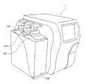
图1是根据本发明的血液分析器的前透视图;Figure 1 is a front perspective view of a blood analyzer according to the present invention;
图2是根据本发明的血液分析器的后透视图;Figure 2 is a rear perspective view of a blood analyzer according to the present invention;
图3是接附到根据本发明的血液分析器的容器容纳单元的透视图;Fig. 3 is a perspective view of a container accommodating unit attached to the blood analyzer according to the present invention;
图4是根据本发明的血液分析器的试样设定部分的前视图;Fig. 4 is a front view of a sample setting portion of the blood analyzer according to the present invention;
图5是根据本发明的适配器的顶部表面的视图;Figure 5 is a view of the top surface of an adapter according to the invention;
图6是根据本发明的适配器的前视图;Figure 6 is a front view of an adapter according to the invention;
图7是根据本发明的适配器的侧视图;Figure 7 is a side view of an adapter according to the invention;
图8是说明根据本发明的适配器插入试样机架的状态的图;8 is a diagram illustrating a state where an adapter according to the present invention is inserted into a sample rack;
图9是说明根据本发明的血液分析器的试样设定部分的操作的图;9 is a diagram illustrating the operation of a sample setting section of the blood analyzer according to the present invention;
图10是说明根据本发明的血液分析器的试样设定部分的操作的图;Fig. 10 is a diagram illustrating the operation of a sample setting section of the blood analyzer according to the present invention;
图11是说明根据本发明的血液分析器的试样设定部分的操作的图;Fig. 11 is a diagram illustrating the operation of a sample setting section of the blood analyzer according to the present invention;
图12是根据本发明的血液分析器的检测部分的前视图;Fig. 12 is a front view of a detection portion of a blood analyzer according to the present invention;
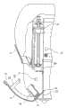
图13是根据本发明的血液分析器的吸液管水平驱动部分的前视图;Fig. 13 is a front view of the pipette horizontal driving part of the blood analyzer according to the present invention;
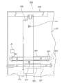
图14是根据本发明的血液分析器的吸液管竖直滑动部分的前视图;Fig. 14 is a front view of the vertical sliding part of the pipette of the blood analyzer according to the present invention;
图15是图14中的B-B箭头方向的视图;Fig. 15 is the view of B-B arrow direction among Fig. 14;
图16是根据本发明的血液分析器的吸液管竖直滑动部分的前视图;Fig. 16 is a front view of the vertical sliding part of the pipette of the blood analyzer according to the present invention;
图17是根据本发明的吸液管竖直滑动部分和吸液管水平驱动部分的主要部分的前视图;Fig. 17 is a front view of main parts of the pipette vertical slide portion and the pipette horizontal drive portion according to the present invention;
图18是根据本发明的吸液管竖直滑动部分和吸液管水平驱动部分的主要部分的左侧视图;Fig. 18 is a left side view of main parts of a pipette vertical slide portion and a pipette horizontal drive portion according to the present invention;
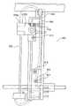
图19是根据本发明的吸液管竖直驱动部分的左侧视图;Fig. 19 is a left side view of the vertical driving part of the pipette according to the present invention;
图20是图19中的C-C箭头方向的视图;Fig. 20 is the view of C-C arrow direction among Fig. 19;
图21是说明根据本发明的吸液管竖直驱动部分的操作的图;Fig. 21 is a diagram illustrating the operation of the pipette vertical driving section according to the present invention;
图22是说明根据本发明的吸液管竖直驱动部分的操作的图;Fig. 22 is a diagram illustrating the operation of the pipette vertical driving section according to the present invention;
图23是根据本发明的检测器的主要部分的部分剖面的前视图;Fig. 23 is a front view, partially in section, of a main part of a detector according to the present invention;
图24是根据本发明的检测器的主要部分的部分剖面的侧视图;Fig. 24 is a side view, partially in section, of the main part of the detector according to the present invention;
图25是根据本发明的混合腔的顶部表面的视图;Figure 25 is a view of the top surface of a mixing chamber according to the present invention;
图26是图25所示的混合腔的竖直截面视图;Figure 26 is a vertical cross-sectional view of the mixing chamber shown in Figure 25;
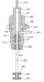
图27是根据本发明的吸液管的竖直截面视图;Figure 27 is a vertical sectional view of a pipette according to the present invention;
图28是根据本发明的清洁器主体的顶部表面的视图;Figure 28 is a view of the top surface of the cleaner body according to the present invention;
图29是图28中的D-D箭头方向的视图;Fig. 29 is the view of D-D arrow direction in Fig. 28;
图30是图28中的E-E箭头方向的视图;Fig. 30 is the view of E-E arrow direction among Fig. 28;
图31是用于说明根据本发明的清洁器主体的操作的图;Fig. 31 is a diagram for explaining the operation of the cleaner main body according to the present invention;
图32是用于说明根据本发明的清洁器主体的操作的图;Fig. 32 is a diagram for explaining the operation of the cleaner main body according to the present invention;
图33是用于说明图28中所示的清洁器主体和吸液管之间的位置关系的图;Fig. 33 is a diagram for explaining the positional relationship between the cleaner main body and the suction pipe shown in Fig. 28;
图34是根据本发明的另一个典型吸液管的竖直截面视图;Figure 34 is a vertical cross-sectional view of another exemplary pipette according to the present invention;
图35是图34中所示的吸液管的主要部分的放大视图;Fig. 35 is an enlarged view of main parts of the pipette shown in Fig. 34;
图36是图35中所示的吸液管的端部视图;Figure 36 is an end view of the pipette shown in Figure 35;
图37是图35中的A-A箭头方向的视图;Fig. 37 is the view of A-A arrow direction among Fig. 35;
图38是示出了在根据本发明的血液分析器中使用的另一种典型适配器的顶部表面的视图;Fig. 38 is a view showing the top surface of another typical adapter used in the blood analyzer according to the present invention;
图39是图38中所示的适配器的前视图;Figure 39 is a front view of the adapter shown in Figure 38;
图40是图38中所示的适配器的侧视图;Figure 40 is a side view of the adapter shown in Figure 38;
图41是说明在图38中所示的适配器插入根据本发明的试样机架的状态的图;FIG. 41 is a diagram illustrating a state where the adapter shown in FIG. 38 is inserted into the sample rack according to the present invention;
图42是根据本发明的流体回路图;Figure 42 is a fluid circuit diagram according to the present invention;
图43是根据本发明的电路图;Figure 43 is a circuit diagram according to the present invention;
图44是示出了根据本发明的血液分析器的操作的流程图;Fig. 44 is a flowchart showing the operation of the blood analyzer according to the present invention;
图45是示出了根据本发明的血液分析器的操作的流程图;Fig. 45 is a flowchart showing the operation of the blood analyzer according to the present invention;
图46是示出了根据本发明的血液分析器的操作的流程图;Fig. 46 is a flowchart showing the operation of the blood analyzer according to the present invention;
图47是根据本发明的流体回路的主要部分的详细图;Figure 47 is a detailed view of the main part of the fluid circuit according to the present invention;
图48是根据本发明的注射泵单元的前视图;Figure 48 is a front view of a syringe pump unit according to the present invention;
图49是根据本发明的注射泵单元的竖直截面视图;Figure 49 is a vertical sectional view of a syringe pump unit according to the present invention;
图50是用于说明图48中所示的注射泵单元的主要部分的操作的图;Fig. 50 is a diagram for explaining the operation of the main part of the syringe pump unit shown in Fig. 48;
图51是用于说明图48中所示的注射泵单元的主要部分的操作的图;FIG. 51 is a diagram for explaining the operation of the main part of the syringe pump unit shown in FIG. 48;
图52是用于说明图48中所示的注射泵单元的主要部分的操作的图;Fig. 52 is a diagram for explaining the operation of the main part of the syringe pump unit shown in Fig. 48;
图53是根据本发明的气泡传感器的顶部表面的视图;Figure 53 is a view of the top surface of an air bubble sensor according to the present invention;
图54是图53中的A-A箭头方向的视图;Fig. 54 is the view of A-A arrow direction among Fig. 53;
图55是用来处理来自根据本发明的气泡传感器的各输出信号的信号处理电路图;Fig. 55 is a signal processing circuit diagram for processing each output signal from the air bubble sensor according to the present invention;
图56是示出了图55中所示的电路的信号的时间图;Figure 56 is a time diagram showing the signals of the circuit shown in Figure 55;
图57是示出了图55中所示的电路的信号的时间图;Figure 57 is a time diagram showing the signals of the circuit shown in Figure 55;
图58是示出了另一个典型的信号处理电路的电路图;Fig. 58 is a circuit diagram showing another typical signal processing circuit;
图59是示出了图58中所示的电路的信号的时间图;Figure 59 is a timing diagram showing the signals of the circuit shown in Figure 58;
图60是示出了另一个典型的开关电路的电路图;FIG. 60 is a circuit diagram showing another typical switching circuit;
图61是示出了在根据本发明的血液分析器中使用的另一个典型的适配器的顶部表面视图;Figure 61 is a top surface view showing another typical adapter used in the blood analyzer according to the present invention;
图62是图61中所示的适配器的前视图;Figure 62 is a front view of the adapter shown in Figure 61;
图63是图61中的S-S箭头方向的视图;Figure 63 is a view in the direction of the S-S arrow in Figure 61;
图64是图61中所示的适配器的主要部分的顶部表面的视图;Figure 64 is a view of the top surface of the main part of the adapter shown in Figure 61;
图65是图64中的T-T箭头方向的视图;Fig. 65 is the view of the T-T arrow direction in Fig. 64;
图66是用于说明图61中所示的适配器插入试样机架的状态的图;FIG. 66 is a diagram illustrating a state where the adapter shown in FIG. 61 is inserted into the sample rack;
图67是根据本发明的另一个实施例的吸液管的截面视图;以及Figure 67 is a cross-sectional view of a pipette according to another embodiment of the present invention; and
图68是图67中所示的吸液管的主要部分的正视图。Fig. 68 is a front view of the main part of the pipette shown in Fig. 67 .
具体实施方式Detailed ways
接下来将描述根据本发明的一个实施例的血液分析器,以作为试样分析器的一个例子。Next, a blood analyzer according to an embodiment of the present invention will be described as an example of a sample analyzer.
根据本发明的该血液分析器最好是自动化的。这里的“自动的”血液分析器指这样一种血液分析器,即,该血液分析器允许使用者在该分析器中设置至少一个试样容器,且该血液分析器能够自动检测包含在该试样容器中的血液试样的成分,计算分析项的值,以及输出计算的结果。The blood analyzer according to the invention is preferably automated. The "automatic" blood analyzer here refers to a blood analyzer that allows the user to set at least one sample container in the analyzer, and the blood analyzer can automatically detect the samples contained in the sample container. The composition of the blood sample in the sample container is calculated, the value of the analysis item is calculated, and the calculated result is output.
该血液分析器适于分析哺乳动物的血液试样,例如人类。The blood analyzer is suitable for analyzing blood samples from mammals, such as humans.
当血液试样是人类的血液试样时,典型的分析项(测量/分析项)包括红细胞的数目(RBC)、白细胞的数目(WBC)、血色素的量(HGB)、血球比容的值(HCT)、血小板的数目(PLT)、平均红细胞体积(MCV)、平均红细胞血红蛋白量(MCH)以及平均红细胞血红蛋白浓度(MCHC)。When the blood sample is a human blood sample, typical analysis items (measurement/analysis items) include the number of red blood cells (RBC), the number of white blood cells (WBC), the amount of hemoglobin (HGB), the value of hematocrit ( HCT), the number of platelets (PLT), mean corpuscular volume (MCV), mean corpuscular hemoglobin (MCH) and mean corpuscular hemoglobin concentration (MCHC).
至于测量原理,最好使用包层流(sheath flow)电阻抗方法来测量RBC和PLT、使用电阻抗方法来测量WBC,以及使用比色法测量HGB。要被分析的血液试样通过从受试者采样血液进入试样容器(血液采样管)来获得。该血液试样可以是全血试样或者是预先稀释到预定浓度的试样。As for the measurement principle, it is preferable to measure RBC and PLT using the sheath flow electrical impedance method, WBC using the electrical impedance method, and HGB using the colorimetric method. A blood sample to be analyzed is obtained by sampling blood from a subject into a sample container (blood sampling tube). The blood sample may be a whole blood sample or a pre-diluted sample to a predetermined concentration.
特别地,当从婴儿采样的血液时,血液试样的量小,这样将该血液试样预先稀释到预定的浓度(例如,稀释26倍)。In particular, when blood is sampled from an infant, the amount of the blood sample is small, so the blood sample is diluted to a predetermined concentration (for example, 26-fold dilution) in advance.
在血液分析器中使用的试样容器是通常的真空血液采样管(用橡胶帽密封),和每个具有外径12到15mm长度不超过85mm的通常的开口血液试样容器(具有开口),以及每个具有外径大约15mm长度大约20mm的受控血液容器。The sample containers used in the blood analyzer are ordinary vacuum blood sampling tubes (sealed with rubber caps), and ordinary open blood sample containers (with openings) each having an outer diameter of 12 to 15 mm and a length not exceeding 85 mm, and controlled blood containers each having an outer diameter of about 15 mm and a length of about 20 mm.
用于分析所要求的血液试样的数量,例如在全血试样的情况下为10到15微升,在预先稀释的血液试样的情况下为250到350微升。The quantity of blood sample required for the analysis is, for example, 10 to 15 microliters in the case of a whole blood sample and 250 to 350 microliters in the case of a pre-diluted blood sample.
该血液分析器包括一主体和一容器容纳单元。该主体最好容纳在外壳中,该容器容纳单元可拆卸地接附到外壳的侧壁上。该主体包括设置在外壳的前上部分的显示部分。该显示部分包括用于显示分析结果的LCD(液晶显示屏)。如果用于输入分析条件的触摸面板与LCD一体设置,可以增强分析器的可操作性,也节省了空间。The blood analyzer includes a main body and a container accommodating unit. The main body is preferably accommodated in a housing, and the container receiving unit is detachably attached to a side wall of the housing. The main body includes a display portion provided at a front upper portion of the housing. The display section includes an LCD (Liquid Crystal Display) for displaying analysis results. If the touch panel for inputting analysis conditions is integrated with the LCD, the operability of the analyzer can be enhanced and space can be saved.
设置在外壳中的是:试样设定部分,其中使用者设置试样容器;检测部分,其中试样被从试样容器定量分配和稀释,且检测试样的血液成分;流体控制部分,其包括流体控制装置,用于控制在检测部分定量分配和稀释试样所需要的流体;电控制板部分,其容纳用于电控制检测部分、流体控制部分和显示部分的电子组件;电源部分,用于将从商用电源输入的AC(交流)电压转化为较低电平的DC(直流)电压;以及打印部分,用于打印出分析结果。Provided in the housing are: a sample setting section in which a user sets a sample container; a detection section in which a sample is quantitatively dispensed and diluted from the sample container, and blood components of the sample are detected; a fluid control section in which Including the fluid control device, used to control the fluid required to quantitatively distribute and dilute the sample in the detection part; the electric control board part, which houses the electronic components for the electric control detection part, fluid control part and display part; the power supply part, with It is used to convert the AC (alternating current) voltage input from the commercial power supply into a lower level DC (direct current) voltage; and the printing part is used to print out the analysis results.
最好在考虑操作和维护的容易性,以及产热性的情况下正确地布置这些部分。It is better to arrange these parts correctly considering the ease of operation and maintenance, and heat generation.
例如,当试样设定部分设置得邻近外壳的前面,且一个开启/关闭盖(试样设定面板)设置在外壳的前面时,使用者可以很容易地到达试样设定部分,以通过开启该盖来设置试样设定部分中的试样容器。此外,该试样容器这样设置有利地被该盖保护。For example, when the sample setting portion is provided adjacent to the front of the case, and an open/close cover (sample setting panel) is provided on the front of the case, the user can easily reach the sample setting portion to pass Open the cover to set the sample container in the sample setting section. Furthermore, the arrangement of the sample container is advantageously protected by the cover.
例如,当检测部分被设置为外壳的右侧壁或者左侧壁内部的一个单元时,通过拆卸外壳的一个侧板,该检测部分可以很容易地到达,以维护和检查。该检测部分最好包括吸液管驱动装置、混合腔以及检测器,用于定量地通过吸液管从试样容器分配血液试样,正确地稀释血液试样和正确地分析血液成分。For example, when the detection part is provided as a unit inside the right side wall or the left side wall of the casing, the detection part can be easily accessed for maintenance and inspection by detaching one side plate of the casing. The detection section preferably includes a pipette drive, a mixing chamber and a detector for quantitatively dispensing the blood sample from the sample container through the pipette, properly diluting the blood sample and correctly analyzing blood components.
这里使用的吸液管是通常称为“刺穿器”或者“针”的吸液管,其具有用于刺穿试样容器的帽的锐利的尖端。The pipette used here is a pipette commonly referred to as a "piercer" or "needle" having a sharp point for piercing the cap of a sample container.
当流体控制部分设置在与检测部分相对的或者相对于该检测部分是背靠背的关系的另一侧壁的内部时,通过拆卸外壳的另一个侧板,该流体控制部分可以很容易地到达,以维护和检查。When the fluid control part is arranged inside the other side wall opposite to the detection part or in a back-to-back relationship with respect to the detection part, the fluid control part can be easily accessed by detaching the other side plate of the housing to maintenance and inspection.
由于设置在流体控制部分中的电磁阀和泵会产生噪声,给出了使这些组件消音的考虑,以减小整个流体控制部分的噪音(包括突然的噪音)到例如不大于45dB的水平。特别地,诸如外部压缩机之类的压力装置不作为流体回路的驱动源使用,但是,替代的,在外壳中设置负压泵,以方便该血液分析器的操作。用作负压源的该负压泵在血液分析器中频繁地被致动,要求特别考虑消音。Since the solenoid valves and pumps disposed in the fluid control section generate noise, consideration is given to silence these components to reduce the noise (including sudden noise) of the entire fluid control section to a level not greater than 45 dB, for example. In particular, a pressure device such as an external compressor is not used as a driving source for the fluid circuit, but instead, a negative pressure pump is provided in the housing to facilitate the operation of the blood analyzer. This negative pressure pump used as a negative pressure source is frequently actuated in blood analyzers, requiring special consideration for noise reduction.
电源部分包括诸如晶体管和二极管之类的产热组件。因此,该电源部分设置在外壳的最上面部分,且在外壳中设置通风器(排气孔),以自然冷却电源。该结构不需要提供风扇来强制冷却,且确保了消音和节省了空间。当电源部分设置在最上面部分时,防止其它组件受到由电源部分产生的热产生的不利影响。The power section includes heat-generating components such as transistors and diodes. Therefore, the power supply part is provided at the uppermost part of the casing, and a ventilator (exhaust hole) is provided in the casing to naturally cool the power supply. This structure does not need to provide a fan for forced cooling, and ensures noise reduction and space saving. When the power supply part is disposed at the uppermost part, other components are prevented from being adversely affected by heat generated by the power supply part.
当容器容纳单元设置在外壳的侧壁中时,试样容器可以容易地被替换,且该容器容纳单元可以容易地连接到分析器主体。该容器容纳单元最好适于容纳用于包含要在分析器主体中使用的稀释液和溶血剂的至少两个容器,以及用于存储要被从分析器主体排放的废液的一个容器。When the container accommodating unit is provided in the side wall of the housing, the sample container can be easily replaced, and the container accommodating unit can be easily connected to the analyzer main body. The container accommodating unit is preferably adapted to accommodate at least two containers for containing a diluent and a hemolyzing agent to be used in the analyzer body, and a container for storing waste liquid to be discharged from the analyzer body.
示例example
接下来通过另一个实施例并参考附图详细描述本发明。然而,应当理解,本发明并不局限于此。Next, the present invention will be described in detail by another embodiment with reference to the accompanying drawings. However, it should be understood that the present invention is not limited thereto.
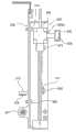
图1和2分别是根据本发明的实施例的血液分析器的前透视图和后透视图。1 and 2 are front and rear perspective views, respectively, of a blood analyzer according to an embodiment of the present invention.
如图所示,分析器主体1容纳在外壳2中,且包括设置在外壳2的前上部分的显示部分3、设置在外壳2的前面右下部分的试样设定面板4和按键5,当设置试样容器时,开启或者关闭试样设定面板,按键5被按下,以开启该试样设定面板4。As shown in the figure, the analyzer
在外壳2的右侧板内部设置用于容纳试样容器的试样设定部分6,以及检测部分7,用于定量分配来自试样容器的试样、稀释该试样和准备分析试样。Inside the right side panel of the
在外壳2的左侧板内部提供流体控制部分8,其共同容纳诸如阀门和泵之类的流体装置,以在检测部分7中控制流体的定量分配和试样的稀释。在外壳2的后侧板内部提供电控制板部分9,其容纳一个板,该板安装有用于电控制该检测部分7、流体控制部分8和显示部分3的电控制装置。Inside the left side panel of the
在外壳2的顶板内部提供电源部分10和打印部分11,该电源部分10用于将供应到其上的商用AC电压转化为DC电压,该打印部分11用于将分析的结果打印出来。Inside the top plate of the
右侧和左侧板、后侧板以及顶板通过螺钉可拆卸地固定,这样各部分可以容易地触及以维护。The right and left side panels, the rear side panel, and the top panel are detachably secured by screws so that each part can be easily accessed for maintenance.
包括产热组件的电源部分10设置在外壳2中的最上位置,通风器(排气孔)12、13设置为包围外壳2中的电源部分10,如图2所示。因此,被电源部分10加热的空气通过通风器12、13排出,以自然空气冷却,而不对分析器的其它组件产生热影响。即,该电源部分10不需要强制空气冷却装置,例如冷却风扇,这样可以实现分析器的尺寸减小和噪音减小。A
如图3所示,组合地容纳分别包含稀释液和溶血剂的容器101、103,以及用于存储废液的容器102的容器的容纳单元100接附到分析器主体1的左侧面。As shown in FIG. 3 , an
试样设定部分的结构和操作Structure and operation of the sample setting section
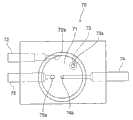
图4是示出了试样设定部分6的结构的前视图。如图所示,试样设定面板4在箭头S方向上可枢转地围绕支撑轴14支撑,且在箭头S方向上由未示出的弹簧设置偏压。在该试样设定面板4上,按键5围绕支撑轴15可枢转地支撑,且在箭头T方向上由弹簧16设置偏压。FIG. 4 is a front view showing the structure of the
设置在该试样设定面板4的上部边缘上的爪钩17与按键5的下部边缘接合,以防止试样设定面板4在箭头S方向上开启。该试样设定面板4设置有圆柱形的试样机架18,用于容纳试样容器。The
如图4所示,在试样设定部分6中,设置了后面要描述的适配器检测传感器(光断路器)J1和适配器识别传感器(光断路器)J2。As shown in FIG. 4, in the
图5、6和7分别是当试样容器(血液采样管)设置在试样机架18中时,要被预先插入试样机架18中的适配器AD1的顶部表面视图、前视图和侧视图。如图所示,该适配器AD1包括圆柱形部分20和容纳托盘22,该圆柱形部分20用作试样容器支撑部分,其具有与试样容器的下面部分接合的圆柱形的凹槽19,该容纳托盘22围绕凹槽19的入口29设置,用于容纳从该试样容器中溢出的试样。该容纳托盘22与圆柱形部分20一体设置。具有深度为45mm,内径为16.5mm的凹槽19的一个适配器,以及具有深度为45mm,内径为13.6mm的凹槽19另一个适配器准备为适配器AD1。因此,这些适配器可以用于具有不同的外径的两种类型的试样容器。5, 6 and 7 are respectively a top surface view, a front view and a side view of the adapter AD1 to be pre-inserted into the
从容纳托盘22向上突伸出的辨认件23设置在容纳托盘22的周边部分中。该辨认件23由适配器检测传感器(光断路器)J1(图4)感测到,以便同时检测适配器AD1是否被设置在试样机架中和该试样设定面板4是否开启和关闭。An identification piece 23 protruding upward from the accommodation tray 22 is provided in a peripheral portion of the accommodation tray 22 . The identification member 23 is sensed by the adapter detection sensor (photo interrupter) J1 (FIG. 4) to simultaneously detect whether the adapter AD1 is set in the sample rack and whether the
从容纳托盘22的下部表面向下伸出的伸长的突出部27设置在圆柱形部分20的外表面上。当适配器AD1插入试样机架18时,如图8所示,该突出部27装配到试样机架的槽口28中(图4),以使该适配器AD1相对于试样机架18定位。由此,确定了该容纳托盘22的位置。在以上的示例中,突出部27设置在试样机架18中,槽口28设置在圆柱形部分20的外表面上。An
在使用者将具有凹槽19的适配器AD1相对于在试样机架18中的试样容器SP1的尺寸设置以后,如图8所示,使用者将该试样容器SP1插入该适配器AD1。After the user has adjusted the adapter AD1 with the
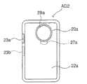
图38、39和40分别是当含有用于测试的受控血液成分(即,受控血液)的试样容器设置在试样机架18中时,要被预先插入试样机架18中的适配器AD2的顶部表面视图、前视图和侧视图。如图所示,该适配器AD2包括圆柱形部分20a和容纳托盘22a,该圆柱形部分20a用作试样容器的支撑部分,其具有与用于受控血液的试样容器的下面部分接合的圆柱形的凹槽19a,该容纳托盘22a围绕凹槽19a的入口29a设置,用于容纳从该受控血液试样容器中溢出的试样。该容纳托盘22a与圆柱形部分20a一体设置。具有深度为15mm,内径为15.6mm的凹槽19a的一个适配器准备为适配器AD2。因此,该适配器可以用于受控血液试样容器。38, 39 and 40 are respectively when the sample container containing the controlled blood component (i.e., controlled blood) for testing is set in the
从容纳托盘22a向上突伸出的辨认件23a设置在容纳托盘22a的周边的上面部分中。该辨认件23a由适配器检测传感器(光断路器)J1(图4)感测到,以便同时检测适配器AD2是否被设置在试样机架中和该试样设定面板4是否开启和关闭。An
从容纳托盘22a的下部表面向下伸出的伸长的突出部27a设置在圆柱形部分20a的外表面上。当适配器AD2插入试样机架时,如图41所示,该突出部27a装配到试样机架18的槽口28中(图4),以使该适配器AD2相对于试样机架18定位。从而,确定了该容纳托盘22a的位置。An
从容纳托盘22a向下突伸出的辨认件23b设置在容纳托盘22a的周边的下面部分中。该辨认件23b由适配器识别传感器(光断路器)J2(图4)感测到,以识别插入试样机架18的适配器是用于受控血液试样容器SP2的适配器AD2。
在使用者将具有凹槽19a的适配器AD2相对于在试样机架18中的受控血液试样容器SP2的尺寸设置以后,如图41所示,使用者将该受控血液试样容器SP2插入该适配器AD2。After the user sets the adapter AD2 having the
图61和63分别是适配器AD3的顶部表面视图和前视图,该适配器AD3用于具有小容量的开口试样容器,以便存储从婴儿或者小动物上获得的小体积的试样(血液)。图63是图61中的S-S箭头方向的视图。61 and 63 are top surface and front views, respectively, of an adapter AD3 for an open sample container with a small capacity for storing small volume samples (blood) obtained from infants or small animals. Fig. 63 is a view in the direction of the S-S arrow in Fig. 61 .
当试样容器设置在试样机架18中时,适配器AD3预先插入试样机架18中。这样设置了弹性地支撑试样容器的适配器AD3。因此,当小体积试样通过后面要描述的吸液管从邻近试样容器底部处吸取时,即使吸液管的尖端接触试样容器的底部,也防止了吸液管和试样容器被损坏。When the sample container is set in the
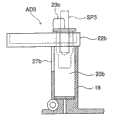
如图所示,适配器AD3包括圆柱形部分20b和围绕该圆柱形部分20b的上部开口设置的容纳托盘22b,以容纳从试样容器溢出的试样。该容纳托盘22b与该圆柱形部分20b一体设置。As shown in the figure, the adapter AD3 includes a
如图63所示,该圆柱形部分20b具有在其中延伸的圆柱形的凹槽19b。用作第一弹性元件的压缩弹簧42插入凹槽19b的底部41,用于试样容器的具有凹槽46的试样容器插入部分43安装在用于容纳试样容器SP3的弹簧42上。试样容器插入部分43的底部45和压缩弹簧42通过穿透底部41的销44相互连接,从而试样容器插入部分43以竖直可滑动的方式支撑在凹槽19b中。即,当试样容器插入部分43被向下压时,由于压力该插入部分43可以向下移动(即,当克服压缩弹簧42的弹力工作时)。该试样容器支撑部分包括圆柱形部分20b、压缩弹簧42、试样容器插入部分43、和销44。As shown in FIG. 63, the
图64是试样容器插入部分43的顶部表面的视图,图65是图64中的T-T箭头方向的视图。如图所示,凸缘47设置在试样容器插入部分43中的凹槽46的上部开口的周边。用于定位试样容器SP3的且与凹槽46同轴的第二弹性元件48被环形保持板49按压,且被螺钉40紧固。该第二弹性元件48由环形硅橡胶板制成,且设置有朝着开口的中心突出的四个突出块48a。Fig. 64 is a view of the top surface of the sample
凹槽46的下端部是圆锥形的。当试样容器SP3插入该凹槽46时,试样容器通过突出块48a的弹性朝着凹槽46的中心按压,且具有锥形下端部的凹槽46允许试样容器SP3朝着凹槽的中心进行导向。因此,被插入凹槽46的该试样容器SP3沿着凹槽46的轴线恒定地定位。The lower end of the
在适配器AD3中,具有外径7.5到11mm的试样容器SP3可以容纳在具有深度21mm的凹槽46中。从容纳托盘22b向上突伸出的辨认件23c设置在容纳托盘22b的周边部分处。该辨认件23c由适配器检测传感器(光断路器)J1(图4)感测到,以便同时检测适配器AD3是否被设置在试样机架中和该试样设定面板4是否开启和关闭。In the adapter AD3, a sample container SP3 having an outer diameter of 7.5 to 11 mm can be accommodated in a
从容纳托盘22b的下表面向下伸出的伸长的突出部27b设置在圆柱形部分20b的外表面上。当适配器AD3插入试样机架18时,如图66所示,该突出部27b装配到试样机架18的槽口28中(图4),以使该适配器AD3相对于试样机架18定位。由此,确定了该容纳托盘22b的位置。An
当使用适配器AD3时,在图67和68中所示的具有平顶的吸液管PTb适于用来从试样容器SP3的底部吸取小体积试样。该吸液管PTb将在后面描述。When the adapter AD3 is used, the pipette tube PTb with a flat top shown in FIGS. 67 and 68 is suitable for aspirating small volume samples from the bottom of the sample container SP3. This pipette PTb will be described later.
具有内径16.5mm的适配器AD1通过透明的ABS(丙烯腈-丁二烯-苯乙烯)树脂来模制,具有内径13.6mm的适配器AD1通过红的ABS树脂来模制,适配器AD2通过黑的ABS树脂来模制,适配器AD3通过蓝的ABS树脂来模制。因此,这些适配器AD1、AD2和AD3通过颜色来区分,这样使用者可以选择适配器AD1、AD2和AD3的类型,以及要被使用的试样容器的尺寸。此外,不同的标签可以接附到各适配器,以便区分。为了定位适配器,在试样框架18中可以设置突出部,在各适配器中可以设置槽口(凹槽)。Adapter AD1 having an inner diameter of 16.5 mm was molded by transparent ABS (acrylonitrile-butadiene-styrene) resin, adapter AD1 having an inner diameter of 13.6 mm was molded by red ABS resin, and adapter AD2 was molded by black ABS resin To be molded, the adapter AD3 is molded by blue ABS resin. Therefore, these adapters AD1, AD2, and AD3 are differentiated by color, so that the user can select the type of adapters AD1, AD2, and AD3, and the size of the sample container to be used. Additionally, a different label can be attached to each adapter for differentiation. For positioning the adapters, protrusions can be provided in the
在该结构中,当使用者按压按键5的上端部时,按键5可以在与图4中的箭头T的方向相反的方向中稍微枢转,且按键5的下边缘与爪钩17断开接合。因此,试样设定面板4围绕支撑轴14在箭头S的方向枢转,从而开启,直到试样设定面板4的突出块4a邻接支撑板21,如图9所示。在这样的状态下,使用者将试样容器SP1、SP2或SP3插入试样机架18,并插入适配器AD1、AD2或AD3,如图10所示。In this structure, when the user presses the upper end of the
当试样设定面板4此后关闭时,如图11所示,试样容器SP1(或者SP2、SP3)与试样机架18同轴的保持。按键5具有相对大的表面积(60mm×70mm)。因此,使用者可以在握住试样容器的同时操作按键5。When the
检测部分的结构和操作Structure and operation of detection part
如图12所示,检测部分7包括吸液管水平驱动部分200、吸液管竖直滑动部分300、吸液管竖直驱动部分400、混合腔70和检测器50。As shown in FIG. 12 , the detection part 7 includes a pipette
吸液管水平驱动部分Suction tube horizontal driving part
图13是吸液管水平驱动部分200的前视图。FIG. 13 is a front view of the pipette
如图所示,被动滑轮202和主动滑轮203可旋转地设置在支撑板201上,同步皮带204在滑轮202和203之间伸展。主动滑轮203由设置在支撑板201的后侧上的吸液管往复马达(步进电机)205驱动。As shown in the figure, a driven
导轨206水平地设置在支撑板201的上部上,导向轴207水平地设置在支撑板201的下部上。竖直伸长的水平移动板208的上边缘安装在导轨206上,其下边缘接合沿着导向轴207可滑动的滑动件209,且从水平移动板208后侧伸出的连接件210与同步皮带204连接。该水平移动板208具有螺孔211、212,用于固定吸液管竖直滑动件300。The
通过这样的结构,水平移动板208通过马达205的驱动可以水平移动。用于检测水平移动板208的位置的吸液管前部位置传感器(光断路器)J5设置在支撑板201上。With such a structure, the horizontal moving
吸液管竖直滑动部分Suction tube vertical sliding part
图14是吸液管竖直滑动部分300的前视图,图15是图14中的B-B箭头方向的视图。如图所示,吸液管竖直滑动部分300包括由支撑件301竖直支撑的导向轴302,和在导向轴302上可滑动的吸液管保持器303,在该吸液管保持器中竖直地保持一吸液管PT。FIG. 14 is a front view of the vertical sliding
支撑件301包括纵向伸长的导向槽304。从吸液管保持器303水平伸出的导向杆305插入导向槽304中,使得其被导向槽304引导,从而该吸液管保持器303可以在导向轴302上稳定地竖直滑动。该支撑件301具有槽口306、307,螺钉通过槽口306、307延伸,以将支撑件301固定到水平移动板208上,如图13所示。The supporting
此外,该吸液管保持器303具有导向轮308,其接合吸液管竖直驱动部分400的导向臂(后面将描述),以协同导向臂用于竖直上下移动吸液管保持器303。In addition, the
用于清洁吸液管PT的外部和内部的清洁器S(吸液管清洁装置)设置在支撑件301的下部,吸液管PT插入该清洁器S。当吸液管保持器303位于支撑件301的最上位置时(图14中所示的位置),吸液管PT的锐利尖端插入清洁器S。A cleaner S (pipetic cleaning device) for cleaning the outside and inside of the pipette PT is provided at the lower portion of the
固定到支撑件301的下部的液体供应/排放接头309、310和311分别通过管312、313和314连接到吸液管PT的邻近端部和清洁器S的端口。Liquid supply/
设置固定到吸液管保持器303的螺钉315和固定到支撑件301的突出部317的螺钉316,用来固定隔板318,如图16所示。如图16所示固定的隔板318将吸液管保持器303固定在支撑件301的最上位置,用于防止吸液管PT的锐利尖端从清洁器S收回。A
吸液管竖直滑动部分300首先停留在水平移动板208上,如图13所示,隔板318固定其上,在螺钉319、320(图17)通过槽口306、307旋入螺孔211、212以后,隔板318通过旋开螺钉315、316来卸下。因此,吸液管竖直滑动部分300可以安全地安装在吸液管水平驱动部分200上,而使用者不可能被吸液管PT的尖端损伤。当在吸液管PT中出现诸如堵塞之类的问题时,该吸液管竖直滑动部分300被整个替换。此时,使用隔板318来安全地实施替换操作。The vertical sliding
图17和18分别是示出了吸液管竖直滑动部分300安装在吸液管水平驱动部分200上的状态的前视图和左侧视图。如图所示,吸液管竖直滑动部分300的吸液管保持器303的一端303a的截面具有十字形,使得其被插入吸液管竖直驱动部分400的主臂中(在后面描述)。17 and 18 are a front view and a left side view showing a state where the pipette
吸液管竖直驱动部分Suction tube vertical drive part
图19是吸液管竖直驱动部分400的左侧视图,图20是图19中的C-C箭头方向的视图。Fig. 19 is a left side view of the pipette vertical driving
如图19所示,吸液管竖直驱动部分400包括水平延伸的伸长的主臂401、穿过主臂401垂直延伸且可旋转地由支撑板412支撑的螺纹轴402、固定到主臂401且与螺纹轴402螺纹接合的螺帽403、平行于支撑板412上的螺纹轴402设置的滑轨404a、设置在主臂401的左端且与滑轨404a可滑动地接合以引导滑动主臂401的滑动件404b,以及固定到支撑板412的吸液管上下往复马达(步进电机)405。As shown in FIG. 19, the pipette vertical driving
滑轮406和407分别固定到螺纹轴402和马达405的输出轴的上端,同步皮带408在滑轮406和407之间伸展。因此,主臂401通过马达405的驱动可竖直上下移动。在支撑板412上设置的吸液管顶部位置传感器J4用来检测主臂401到达最上位置。
导向臂409水平固定到(垂直固定到纸的)主臂401的右端,并与吸液管竖直滑动部分300(图18)的导向轮308接合。主臂401具有十字形的凹槽410,其设置在其与吸液管保持器303(图17和18)的十字形端部303a相对的表面上。如图20所示,吸液管保持器303的端部303a在箭头X方向可移动的插入到具有适当的间隙的凹槽410。在这样的情况下,主臂401竖直移动的力直接传送到吸液管保持器303上。The
锁定杆411穿过主臂401的中间部分竖直延伸,其上端弯曲部分接合主臂401。在该实施例中,主臂401由铝合金(A5052)构成,且具有20mm×26mm的截面和108mm的长度。导向臂409通过将0.5mm厚的钢板(SECC)折叠为截面是开口方形来制备,且具有180mm的长度。The locking
吸液管水平驱动部分、吸液管竖直滑动部分和吸液管竖直驱动部Suction pipe horizontal drive part, pipette vertical slide part and pipette vertical drive part分的操作points of operation
当血液试样被定量地从设置在试样机架18中的试样容器SP1分配到试样设定部分6时,驱动吸液管往复马达205,以将吸液管保持器303的端部303a插入到主臂401的凹槽410中,如图20所示。When the blood sample is quantitatively dispensed from the sample container SP1 set in the
驱动吸液管上下往复马达405来向上移动主臂401,直到吸液管顶部位置传感器J4促动(图4和19)。随着端部303a安装到凹槽410中,螺纹轴402、吸液管PT和试样容器SP1的中心处于同一个平面,且由螺纹轴402施加到吸液管PT上的力矩最小化。因此,当吸液管PT由马达405下降时,马达405的转矩有效地转化为吸液管下降力。Drive the pipette up and down reciprocating
然后,驱动马达405以穿过防止试样容器抬起的制动器26的通孔26a下降吸液管PT,且允许吸液管PT竖直到达试样容器SP1的底部,如图22所示。当试样容器SP1是具有橡胶帽的真空血液采样管时,必须用吸液管PT的尖端刺穿该橡胶帽。因此,当下降吸液管PT以刺穿橡胶帽时,供应到马达405的来自驱动电路部分(以后描述)的输入电流比通常情况的要大,以提供更大的输出转矩。Then, the
当吸液管PT下降时,锁定杆411与设置在突出块24中的锁定孔25接合,该突出块24向试样设定面板4的内部伸出,如图22所示,因此,当试样设定面板4无意地开启时,可以防止吸液管PT和试样容器SP1损坏。当试样容器SP2设置在试样机架18中且插入适配器AD2时,如图41所示,促动适配器识别传感器J2。因此,后面要描述的控制部分500控制控制吸液管PT的下降距离,以允许吸液管PT的尖端实际上到达试样容器SP2的底部。When the pipette PT is lowered, the locking
在图22所示的状态下,使用吸液管PT来从试样容器SP1采样血液试样。In the state shown in FIG. 22 , a blood sample is sampled from the sample container SP1 using the pipette PT.
一旦完成血液试样的吸入,吸液管PT回到如图21所示的位置。虽然当吸液管PT从试样容器SP1移开时,由于橡胶帽夹住吸液管PT,试样容器SP1可能连同吸液管PT一起被抬起,但是制动器26防止橡胶帽被一起抬起。Once the aspiration of the blood sample is complete, the pipette PT returns to the position shown in FIG. 21 . Although when the pipette PT is removed from the sample container SP1, since the rubber cap pinches the pipette PT, the sample container SP1 may be lifted together with the pipette PT, but the
当吸液管PT回到如图21所示的位置时,驱动吸液管往复马达205沿图20中所示的箭头X方向相反的方向从主臂401的凹槽410收回吸液管保持器303的端部303a,然后,随着导向轮308接触导向臂409的内表面旋转,将吸液管PT移到混合腔70和检测器50的上侧。然后,驱动吸液管上下马达405,从而其驱动力通过主臂401、导向臂409和导向轮308传送到吸液管保持器303。这样,该吸液管PT下降然后抬起。When the pipette PT returns to the position shown in FIG. 21, drive the
检测器的结构Detector structure
图23和24分别是检测器50的主要部分的部分剖面前视图和部分剖面侧视图。检测器50由透明聚砜树脂制成。如图所示,检测器50包括第一、第二和第三容器腔51、52和53,用于包含用于分析的液体。第一容器腔51具有朝着大气开放的上部。第一容器腔51和第三容器腔53相互连通。23 and 24 are a partially sectional front view and a partially sectional side view of the main part of the
红宝石孔口盘54设置为第一容器腔51和第二容器腔52之间的隔离件,且盘54具有直径80μm的喷孔55。第二容器腔52设置有喷嘴56。该喷嘴56由喷嘴支撑件57和第一电极58支撑,且穿过第二容器腔52延伸,其顶端朝着喷孔55,其末端连通液体供应接头59。第一电极58由不锈钢制成,且暴露在第二容器腔52的内部。A ruby orifice disc 54 is provided as a partition between the first vessel cavity 51 and the
检测器50还包括用于将稀释液和溶血剂供应到第一容器腔51的喷嘴60、61,用于将液体供应到第二容器腔52/从第二容器腔排出液体的接头63、64,以及设置在第三容器腔53的底部中的液体排放接头65和气泡注射接头66。The
如图24所示,检测器50还包括在第一容器腔51中伸出的第二铂电极67,以及分别设置在第三容器腔53的相对侧面上的发光二极管68和光敏二极管69。发光二极管68发出具有555nm波长的光,光敏二极管69检测透过第三容器腔53的光强度。使用发光二极管68和光敏二极管69来测量血色素的量(HGB)。As shown in FIG. 24 , the
如后面将要描述的,使用第一和第三容器腔51、53来准备白细胞测量样本,使用第一和第二容器腔51、52来计数白细胞、血小板和红细胞的数目。As will be described later, the first and third container chambers 51, 53 are used to prepare leukocyte measurement samples, and the first and
混合腔(用于混合液体的容器)的结构Structure of the mixing chamber (container for mixing liquids)
图25和26分别是混合腔70的正视图和侧视图。该混合腔70包括用于混合血液试样的容器部分71。该容器部分71具有圆柱形形状,其顶部朝着大气开放。稀释液供应接头72设置在容器部分71的上部。用于排出液体混合物的接头73、用于从容器部分71排出剩余液体的接头74,以及用于注射气泡(空气)以搅动容器部分71中的液体的接头75设置在容器部分71的底部。25 and 26 are front and side views of mixing
接头72、73、74、75分别连接到液体供应端口72a、液体排放端口73a、74a和空气供应端口75a,这些端口与容器部分71的内表面连通。液体供应端口72a打开,这样从上部沿着容器部分71的内周围表面供应液体。如后面将要描述的,当稀释液供应到混合腔70中,以清洁该腔时,随着稀释液从液体供应端口72a注入,容器部分71的内表面被充分清洁。
混合腔70由诸如聚醚酰胺之类的具有耐化学性能的热塑树脂注模制成。使容器部分71的内表面粗糙到Ra为0.29μm的算术平均表面粗糙度,使得其对于稀释液获得充分高的湿润性。因此,从液体供应端口72a注入的稀释液供应到容器部分71的底部,而在其内表面上没有残留液滴,这样预先提供的血液试样可以精确地被稀释预定的倍数。The mixing
吸液管和清洁器(吸液管清洁装置)的结构和操作Construction and operation of pipettes and cleaners (sipper cleaning devices)
图27是吸液管PT的竖直截面视图。该吸液管PT是不锈钢管,其具有在其中轴向延伸的吸取流动通路31和锐利地切割为α为30度的角的末尖端。当使用具有帽的试样容器SP1时,该帽被该末尖端刺穿。吸取流动通路31的末端由不锈钢密封装置33密封,且吸取端口32在吸液管PT的侧面开口,该吸取端口32的轴线垂直于吸液管PT的轴线延伸。Fig. 27 is a vertical sectional view of the pipette PT. The pipette PT is a stainless steel pipe having a suction flow path 31 axially extending therein and a tip sharply cut at an angle α of 30 degrees. When using the sample container SP1 with a cap, the cap is pierced by the distal tip. The end of the suction flow path 31 is sealed by a stainless steel seal 33, and a
图28是清洁器主体80的正视图。图29和30分别是图28中的D-D箭头方向的视图和E-E箭头方向的视图。如图所示,清洁器主体80具有在其中心延伸的吸液管通孔81,使得吸液管PT从入口81a到出口81b竖直插入吸液管通孔81。该吸液管通孔81具有圆形的截面。FIG. 28 is a front view of the cleaner
该吸液管通孔81包括吸液管导孔82、第一通孔83和第二通孔84,它们以这样的顺序串联地、同轴地从入口81a到出口81b设置。吸液管导孔82内径略大于吸液管PT的外径,该吸液管导孔82用于引导吸液管PT,使得吸液管PT的轴线与第一和第二通孔83、84的轴线对准。The pipette through
另一方面,该第一和第二通孔83、84构成用于清洁吸液管的吸液管清洁孔。第一开口85a和第二开口85b分别形成在第一和第二通孔83、84中。On the other hand, the first and second through
清洁器主体80包括允许在第一开口85a和清洁液体排放接头87之间连通的清洁液体排放通路87a,以及允许在第二开口85b和清洁液体供应接头88之间连通的清洁液体供应通路88a。The
吸液管引导孔82、第一通孔83和第二通孔84分别具有内径D1、D2和D3,它们分别设置为吸液管PT的外径的105%、115%和200%。例如,当吸液管PT具有2.0mm的外径时,D1=2.1mm,D2=2.3mm,D3=4.0mm。The pipette guide hole 82, the first through
当吸液管PT穿过吸液管通孔81从上侧延伸到下侧,清洁液(本实施例中为稀释液)从接头88供应到第二通孔84且从接头87吸取时,如图31所示,清洁液从第二通孔84流入第一通孔83,并从接头87排出,且与吸液管PT的外部均匀接触。When the pipette PT extends from the upper side to the lower side through the pipette through
因此,当吸液管PT以这样的状态在箭头Z的方向上向上移动时,粘附在吸液管PT的外部上(外周边表面)的血液试样等被清洁液冲洗掉并排出。Therefore, when the pipette PT moves upward in the direction of the arrow Z in such a state, the blood sample etc. adhering to the outside (outer peripheral surface) of the pipette PT is washed away by the cleaning liquid and discharged.
当清洁液从接头88流入接头87时,具有吸液管PT的尖端的末端吸取端口32被保持在第一通孔83a中,如图32所示。当清洁液从吸液管PT的邻近端供应到具有吸液管PT的尖端的末端吸取端口32时,已经流过吸液管PT的吸取流动通路31的清洁液从吸液管PT的吸取端口32排出,且通过第一开口85a吸入到接头87,但不排入第二通孔84。这样,清洁了吸液管PT的内部(即,吸液管PT的吸取流动通路31的内表面和吸取端口32)。When the cleaning liquid flows from the joint 88 into the joint 87, the
清洁器主体80和吸液管PT的位置关系在图33中如所示的吸液管PT的轴向显示。如图所示,吸液管PT相对于清洁器主体80定位,吸取端口32的轴线和清洁液排放通路87a的开口85b的轴线形成大于90度的θ角。这是因为实验上观察到了下面的现象。The positional relationship between the cleaner
(1)如果θ≤90°,当清洁完吸液管PT的外部或者内部时,在吸液管PT的吸取流动通路31和吸取端口32中充满的稀释液(以后将要描述)被清洁液排放通路87a中的负压吸出,且在吸取端口32出现空隙。因此,在血液试样通过吸液管PT被吸取而量化前,血液试样被引入吸取端口32中的空隙。因此,由于先前的引入,被吸入到吸液管PT的血液试样的量比预定的量要大,导致了错误的定量。(1) If θ≤90°, when cleaning the outside or inside of the pipette PT, the diluent (to be described later) filled in the suction flow path 31 and
(2)如果θ>90°,在清洁液排放通路87a中的负压不直接在吸取端口32上施加作用。因为当清洁吸液管PT的外部或者内部时,在吸取端口32中不出现空隙,因此确保了精确的定量。(2) If θ > 90°, the negative pressure in the cleaning
另一种示例性的吸液管Another Exemplary Pipette
图34是示出了另一种典型的吸液管PTa的侧视图,当具体真空血液采样管(用橡胶帽密封)作为试样容器SP1使用时,这种典型的吸液管PTa适合用来替代吸液管PT(图27),图35是图34的主要部分的放大视图,图36是吸液管PTa的端视图,图37是图35中的箭头A-A方向的视图。Fig. 34 is a side view showing another typical pipette PTa, which is suitable for use when a specific vacuum blood sampling tube (sealed with a rubber cap) is used as the sample container SP1 Instead of the pipette PTa ( FIG. 27 ), FIG. 35 is an enlarged view of the main part of FIG. 34 , FIG. 36 is an end view of the pipette PTa, and FIG. 37 is a view in the direction of arrow A-A in FIG. 35 .
如图所示,吸液管PTa是具有1.5mm外径的不锈钢管,其具有在其中心延伸的内径为0.5mm的吸取流动通路(流体通路)31a。具有三角锥形状的且朝着顶点T渐缩的尖锐的锥形部分(头部)37在吸液管PTa的末端形成,如图34和35所示。顶点T定位在吸液管PTa的中心轴线上,如图36所示。具有这样的结构使得吸液管PTa的下降力集中在顶点T,从而试样容器SP1的橡胶帽容易被吸液管PTa刺穿。该锥形部分37可以具有圆锥形或者四角锥形。吸液管PTa刺穿的橡胶帽具有大约5mm的厚度。As shown in the drawing, the pipette PTa is a stainless steel pipe having an outer diameter of 1.5 mm, which has a suction flow path (fluid path) 31 a extending at the center thereof with an inner diameter of 0.5 mm. A sharp tapered portion (head) 37 having a triangular pyramid shape and tapering toward the apex T is formed at the tip of the pipette PTa, as shown in FIGS. 34 and 35 . The vertex T is positioned on the central axis of the pipette PTa, as shown in FIG. 36 . With such a structure, the descending force of the pipette PTa is concentrated at the apex T, so that the rubber cap of the sample container SP1 is easily pierced by the pipette PTa. The tapered
和图27中的吸液管PT中一样,吸取流动通路31a具有由不锈钢密封件密封的末端部分。该吸液管PTa具有在其侧壁中开口的吸取端口32a(图35)。该吸取端口32a具有垂直于吸液管PTa的轴线延伸的轴线,且与吸取流动通路31a(图35)流体连通。As in the pipette PT in FIG. 27, the
此外,吸液管PTa具有三个伸长的凹槽34、35和36,其每一个都具有设置在吸液管PTa外表面的槽形形状,并在平行于吸液管PTa的轴线的直线上延伸,如图34所示。锥形部分37具有的长度L1为4mm,凹槽34、35和36具有的长度L2、L4和L6分别为25mm、20mm和30mm。在凹槽34和35之间的间隔L 3为5mm,在凹槽35和36之间的间隔L5为5mm。从降低生产成本的观点出发,凹槽34、35和36最好设置在平行于吸液管PTa的轴线的一直线上。然而,这些凹槽可以设置在平行于吸液管PTa的轴线的两条或者三条直线上,或者可以在吸液管PTa的外表面上螺旋形延伸地设置。In addition, the pipette PTa has three
在吸液管PTa的末端下降以刺穿橡胶帽之后,凹槽34用于使试样容器的内部压力立刻恢复到大气压。当吸液管PTa继续下降时,橡胶帽的一部分进入凹槽34,然后经过吸液管PTa的间隔部分L3被推出。The
当吸液管PTa进一步下降时,橡胶帽的该部分进入凹槽35,且通过吸液管PTa的间隔部分L5被推出,使得通孔被扩大。当吸液管PTa的末端实际上到达试样容器SP1的底部且凹槽36相对于橡胶帽设置时,该橡胶帽的一部分不进入凹槽36。因此,凹槽36用来限定穿过橡胶帽的气孔,且试样容器SP1具有通过气孔充分通向大气的内部开口。这样,试样(血液)通过吸液管PTa顺利地从试样容器SP1吸取。When the pipette PTa is further lowered, the portion of the rubber cap enters the
三个伸长的凹槽34、35和36设置在一直线中,该直线沿着从形成在吸液管PTa末端的三角锥的一脊线的管的轴线延伸,如图36所示。通过这样的结构,橡胶帽在被吸液管PTa刺穿以后,被吸液管PTa的三角锥的脊线部分劈开,凹槽36面对于橡胶帽被劈开部分之一设置。这样,凹槽36可以更有效地限定穿过橡胶帽的气孔。Three
和在吸液管PT中一样,该吸液管PTa的外部由清洁器S清洁。同时,凹槽34、35和36也以这样的方式清洁。结果,在分析器中不需要提供另一个清洁器来只清洁凹槽34、35和36。The outside of the pipette PTa is cleaned by a cleaner S as in the pipette PT. At the same time, the
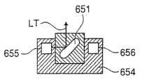
图67和68分别是根据本发明的另一个实施例的吸液管PTb的截面图和其末端的平面图。使用吸液管PTb适于从邻近试样容器的底部吸取小体积试样,该试样容器具有用于存储小体积试样的小容量且上部开口。67 and 68 are a sectional view of a pipette PTb according to another embodiment of the present invention and a plan view of an end thereof, respectively. The use of a pipette PTb is suitable for aspirating a small volume sample from the bottom adjacent to a sample container having a small capacity for storing a small volume sample and being open at the top.
如图所示,吸液管PTb由具有1.5mm的外径的不锈钢管制成,其具有在吸液管PTb中同轴延伸的0.6mm内径的吸取流动通路31b。吸液管PTb具有圆形部分半径为0.4mm的末端,且具有径向穿过末端的凹槽32b。凹槽32b的宽度和吸取流动通路31b的直径一样,凹槽32b的深度为0.3mm。通过这样的末端形状,吸液管PTb的末端接触试样容器的底部,以吸取试样,然后通过凹槽32b吸取该试样进入吸取流动通路31b。As shown in the figure, the pipette PTb is made of a stainless steel pipe having an outer diameter of 1.5 mm, which has a
流体回路和电路的结构Structure of Fluid Loops and Circuits
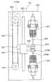
图42是示出了根据本发明的实施例的流体回路的系统框图。在该流体回路中,吸液管PT、清洁器S、混合腔70、检测器50、负压泵P1、液体排放泵P2、空气泵P3、注射泵SR1、SR2、SR4、稀释液腔SC1、溶血剂腔SC2、废液腔WC、稀释液容器101、废液容器102、溶血剂容器103、气泡传感器BS1、BS2以及阀门SV1到SV16、SV18到SV20和SV23到SV28通过流体供应管(流动通路)连接。注射泵SR1、SR4由注射泵马达STM4驱动,注射泵SR2由注射泵马达STM5驱动。可以用步进电机作为注射泵马达STM4、STM5。注射泵SR1、SR4以及注射泵马达STM4集成为注射泵单元PU(如图48所示)。FIG. 42 is a system block diagram illustrating a fluid circuit according to an embodiment of the present invention. In this fluid circuit, suction pipe PT, cleaner S, mixing
稀释液的一个优选例子可以是从Sysmex公司获得的CELLPACK,溶血剂的一个优选例子可以是从Sysmex公司获得的STROMATOLYSERWH。A preferable example of the diluent may be CELLPACK available from Sysmex Corporation, and a preferable example of the hemolytic agent may be STROMATOLYSERWH available from Sysmex Corporation.
图43是示出了根据本发明的实施例的电路的框图。电源部分10将从商用AC电源供应的电压转化为DC电压(12V),该DC电压供应到控制部分500和驱动电路部分501。控制部分500包括微处理器,包括CPU、ROM(只读存储器)和RAM(随机存储器),驱动电路部分501包括驱动电路和I/O(输入/输出)端口。FIG. 43 is a block diagram showing a circuit according to an embodiment of the present invention. The
驱动电路部分501进行输出信号的A-D(模拟-数字)转变,即对适配器检测传感器J1、适配器识别传感器J2、吸液管顶部位置传感器J4、吸液管前部位置传感器J5、用于检测废液腔WC中的负压的压力传感器J6、用于检测在废液腔WC中积累的液体量的浮控开关J7、气泡传感器BS1和BS2、用于允许发光二极管68发射光和用于从光敏二极管69接收输出的血色素检测部分502,以及用于检测电极58和67之间的阻抗变化的阻抗型检测部分503的输出信号实施A-D转化,其中DC恒定电流通过该驱动电路部分501,并且该驱动电路部分501将转化的信号输出到控制部分500。The
控制部分500接收来自驱动电路部分501和触摸面板3b的输出信号,从而处理这些根据预定处理程序接收的信号。基于处理的结果,控制部分500使得驱动电路部分501驱动吸液管上下往复马达405、吸液管往复马达205、注射泵马达STM4、STM5、负压泵P1、液体排放泵P2、空气泵P3以及电磁阀SV1到SV16、SV18到SV20和SV3到SV28。然后,控制部分500控制液晶显示部分3的液晶显示屏3a,以及打印机部分11,以显示和打印出分析条件、分析项、分析结果等。The
血液分析器实施的分析操作Analytical operations performed by blood analyzers
接下来,通过参考如图42所示的流体回路和如图44所示的流程图将要描述通过如图1所示的血液分析器实施的分析操作。Next, analysis operations performed by the blood analyzer shown in FIG. 1 will be described by referring to the fluid circuit shown in FIG. 42 and the flowchart shown in FIG. 44 .
如图44所示,当连接到血液分析器的电源打开时(步骤S1),用于预先清洁所需要的稀释液从容器101传送到稀释液腔SC1(步骤S1a)。然后,当经过包括预备清洁操作的测量准备阶段时(S2),该测量准备阶段是用于分析的预备操作所需要的,准备分析试样所需要的稀释液和溶血剂分别从容器101和103传送到稀释液腔SC1和溶血剂腔SC2(步骤S2a、S2b),且在显示部分3的液晶显示屏3a上显示“准备好”的消息。As shown in FIG. 44, when the power connected to the blood analyzer is turned on (step S1), the diluent required for pre-cleaning is transferred from the
然后,使用者在试样设定部分6(图4)设置试样容器SP1(或者SP2、SP3)(步骤S4)。当在试样容器中这样设置的试样是全血试样时,使用者通过显示部分3的触摸面板3b选择全血模式,当试样是稀释的试样时,使用者选择预先稀释的模式(步骤S5)。Then, the user sets the sample container SP1 (or SP2, SP3) in the sample setting part 6 (FIG. 4) (step S4). When the sample thus set in the sample container is a whole blood sample, the user selects the whole blood mode through the
然后,使用者按压触摸面板3b上的开始按键(步骤S6)。当在步骤S4中试样容器SP1(或者SP2、SP3)没有设置和/或试样设定面板4没有关闭时,传感器J1检测到这样的情况,使得分析器不工作。当设定了试样容器SP1(或者SP2、SP3)和关闭了试样设定面板4时,分析器开始工作。当选择了全血模式(步骤S7),从全血试样准备好用于测量红细胞数目(RBC)的样本和用于测量白细胞数目(WBC)的样本(步骤S8、S9)。Then, the user presses the start button on the
使用在步骤S9中准备好的WBC测量样本,实施WBC和血色素数量(HGB)的测量(步骤S10),然后,测量的WBC和HGB在液晶显示屏3a上显示(步骤S11)。接下来,使用在步骤S8中准备的RBC测量样本来实施RBC的测量,且计算血小板的数目(PLT)、血球比容的值(HCT)以及其它分析项。然后,测量的RBC和各分析项的计算值在液晶显示屏上显示(步骤S13、S14)。Using the WBC measurement sample prepared in step S9, WBC and hemoglobin count (HGB) are measured (step S10), and then the measured WBC and HGB are displayed on the liquid crystal display 3a (step S11). Next, measurement of RBC is carried out using the RBC measurement sample prepared in step S8, and the number of platelets (PLT), the value of hematocrit (HCT), and other analysis items are calculated. Then, the measured RBC and the calculated values of each analysis item are displayed on the liquid crystal display (steps S13, S14).
通过对表示在检测器50的电极58和67之间的阻抗变化的脉冲计数来确定WBC、RBC和PLT。通过对比由光敏二极管68测量的稀释液单独的吸收率(消隐电平)和WBC测量样本的吸收率来确定HGB。根据表示在电极58和67之间的阻抗变化的脉冲最大电平来确定HCT,平均红细胞体积(MCV)、平均红细胞血红蛋白量(MCH)以及平均红细胞血红蛋白浓度(MCHC)从下面的表达式计算:WBC, RBC and PLT are determined by counting pulses representing the change in impedance between
MCV=(HCT)/(RBC)MCV=(HCT)/(RBC)
MCH=(HGB)/(RBC)MCH=(HGB)/(RBC)
MCHC=(HGB)/(HCT)MCHC=(HGB)/(HCT)
然后,实施流体回路清洁操作。一完成清洁操作(步骤S15),稀释液和溶血剂就分别从容器101和103传送到腔SC1和SC2,以等待下一试样的分析(步骤S18、S19),流程返回步骤S3,且在液晶显示屏3a上显示“准备好”,以等待下一试样的分析。当在步骤S7选择了预先稀释模式时,从预先稀释血液试样准备RBC测量样本和WBC测量样本(步骤S16、S17)。在这样的情况下,通过预先稀释全血试样来获得预先稀释试样。因此,应该考虑预先稀释的倍数,使得RBC测量样本和WBC测量样本和那些在全血模式中从全血试样准备的测量样本一样具有相同的稀释倍数。Then, perform a fluid circuit cleaning operation. As soon as the cleaning operation is completed (step S15), the diluent and the hemolyzing agent are transferred from the
接下来,参考在图42中所示的流程系统框图来详细描述在图44中所示的要实施的操作(步骤)。分析器是常闭阀型的,其中在流体回路中的所有阀门通常都是关闭的。Next, operations (steps) to be carried out shown in FIG. 44 are described in detail with reference to the flow system block diagram shown in FIG. 42 . The analyzer is of the normally closed valve type, where all valves in the fluid circuit are normally closed.
稀释液传送操作(步骤S1a、S2a、S18)Diluent transfer operation (steps S1a, S2a, S18)
如图45所示的流程图,当阀门SV13打开时(步骤S21),从负压泵P1给废液腔WC施加负压。从而,稀释液从稀释液容器101经过气泡传感器BS1供应到稀释液腔SC1。当气泡传感器BS1在流动通路没有检测到超过预定数量的气泡(步骤S22),在经过预定的一段时间后,关闭阀门S13(步骤S23、S24)。这样,在稀释液腔SC1中就存储了预定数量的稀释液。As shown in the flowchart of FIG. 45, when the valve SV13 is opened (step S21), negative pressure is applied to the waste liquid chamber WC from the negative pressure pump P1. Thus, the diluent is supplied from the
另一方面,在步骤S22中,当气泡传感器BS1在流动通路中检测到多余预定数量的气泡时,控制部分500判断目前在稀释液容器101中没有稀释液。然后关闭阀门13,且显示部分3在显示屏3a上显示判断(步骤S25、S26)。On the other hand, in step S22, when the bubble sensor BS1 detects more than a predetermined number of bubbles in the flow path, the
使用者用稀释液补充稀释液容器101,或者用新的稀释液容器代替稀释液容器101(步骤S27),且按压显示部分3的触摸面板3b上的“稀释液补充完成”按键(步骤S28)。由此,流程返回步骤S21。The user replenishes the
血剂传送操作(步骤S2b、S19)Blood agent delivery operation (steps S2b, S19)
如图46的流程图所示,当阀门SV9打开时(步骤S31),从负压泵P1给废液腔WC施加负压,从而,溶血剂从溶血剂容器103经过气泡传感器BS2供应到溶血剂腔SC2。当气泡传感器BS2在流动通路没有检测到超过预定数量的气泡(步骤S32),在经过预定的一段时间后,关闭阀门S9(步骤S33、S34)。这样,在溶血剂腔SC2中就存储了预定数量的溶血剂。As shown in the flow chart of FIG. 46, when the valve SV9 is opened (step S31), negative pressure is applied to the waste liquid chamber WC from the negative pressure pump P1, whereby the hemolytic agent is supplied from the
另一方面,在步骤S32中,当气泡传感器BS2在流动通路中检测到多余预定数量的气泡时,控制部分500判断目前在溶血剂容器103中没有溶血剂。然后关闭阀门SV9,且显示部分3在显示屏3a上显示溶血剂的判断(步骤S35、S36)。On the other hand, in step S32, when the air bubble sensor BS2 detects more than a predetermined number of air bubbles in the flow path, the
使用者用溶血剂补充溶血剂容器103,或者用新的溶血剂容器代替溶血剂容器103(步骤S37),且按压显示部分3的触摸面板3b上的“溶血剂补充完成”按键(步骤S38)。由此,流程返回步骤S31。顺便说一下,稀释液传送操作(步骤S1a、S2a、S18)和溶血剂传送操作(步骤S2b、S19)不是同时执行的。即,执行操作中的任一个。The user replenishes the
预先清洁操作(步骤S2)Pre-cleaning operation (step S2)
(1)吸液管PT移到试样机架18的上侧,然后降低吸液管PT,如图22所示。(此时,试样容器SP1没有设定在试样设定部分6中。)然后,阀门SV19打开,以从稀释液腔SC1吸取稀释液进入注射泵SR2,然后阀门SV19关闭。(1) The pipette PT is moved to the upper side of the
(2)阀门SV4、SV11、SV20打开,稀释液从注射泵SR2供应到清洁器S,然后排放到废液腔WC。同时,抬起吸液管PT,实施吸液管PT外部的清洁。当吸液管PT的尖端插入清洁器S的主体80时,停止吸液管PT。这样,完成了吸液管PT的外部的清洁。(2) The valves SV4, SV11, SV20 are opened, and the diluent is supplied from the syringe pump SR2 to the cleaner S, and then discharged to the waste liquid chamber WC. Simultaneously, the suction tube PT is lifted up to perform cleaning of the outside of the suction tube PT. When the tip of the pipette PT is inserted into the
(3)使阀门SV4、SV11、SV20保持开启,吸液管PT被保持在如图32所示的位置。然后,阀门SV7打开,稀释液从注射泵SR2通过注射泵SR1供应到吸液管PT。同时,从吸液管PT的吸取端口32释放的稀释液被排放到废液腔WC,以清洁吸液管PT的内部。(3) The valves SV4 , SV11 , SV20 are kept open, and the pipette PT is kept at the position shown in FIG. 32 . Then, the valve SV7 is opened, and the diluent is supplied from the syringe pump SR2 to the pipette PT through the syringe pump SR1. At the same time, the diluent released from the
(4)当阀门SV7关闭时,从吸液管PT的吸取端口32到第一开口85a的稀释液流被停止,从而完成内部清洁。此时,吸取流动通路31和吸取端口32充满稀释液。另一方面,从第二开口85b到第一开口85a的稀释液流继续,当阀门SV4、SV11、SV20关闭时,该流停止。因此,吸液管PT的吸取端口32保持充满稀释液。(4) When the valve SV7 is closed, the diluent flow from the
RBC测量样本的准备(步骤S8)Preparation of RBC measurement sample (step S8)
(1)由负压泵P1给废液腔WC施加负压,且阀门SV14、SV10打开,从而剩余液体从检测器50和混合腔70排出。此后,阀门SV14、SV10关闭。(1) Negative pressure is applied to the waste liquid chamber WC by the negative pressure pump P1, and the valves SV14 and SV10 are opened, so that the remaining liquid is discharged from the
(2)阀门SV19打开,操作注射泵SR2来吸取,从而从稀释液腔SC1吸取稀释液进入到注射泵SR2。然而,阀门SV19关闭。(2) The valve SV19 is opened, and the syringe pump SR2 is operated to suck, so that the diluent is sucked from the diluent chamber SC1 into the syringe pump SR2. However, valve SV19 is closed.
(3)下降吸液管PT到插入试样容器SP1(图22)。然后,操作注射泵SR1来吸取,从而吸液管PT吸取预定量(10μL)的血液试样。(3) Lower the pipette PT to insert the sample container SP1 (Fig. 22). Then, the syringe pump SR1 is operated to suck, so that the pipette PT sucks a predetermined amount (10 μL) of the blood sample.
(4)然后,抬起吸液管PT。在抬起期间,阀门SV4、SV20、SV11打开,从而,稀释液从注射泵SR2供应到清洁器S中,且排放到废液腔WC,以清洁吸液管PT的外部。然后,阀门SV4、SV20、SV11关闭。(4) Then, lift up the pipette PT. During lift-up, the valves SV4, SV20, SV11 are opened so that diluent is supplied from the syringe pump SR2 into the cleaner S and discharged into the waste chamber WC to clean the outside of the pipette PT. Then, the valves SV4, SV20, SV11 are closed.
(5)打开阀门SV16、SV20,操作注射泵SR2来排放,从而预定量(1.3mL)的稀释液供应到混合腔70。然后,阀门SV16、SV20关闭。(5) The valves SV16 , SV20 are opened, and the syringe pump SR2 is operated to discharge, whereby a predetermined amount (1.3 mL) of diluent is supplied to the mixing
(6)吸液管PT移动到刚好位于混合腔70之上的位置,且下降。然后,操作注射泵SR1来排放,从而吸入到吸液管PT的预定的10μL血液试样被排放到混合腔70中。这样,该血液试样在混合腔70中通过第一阶段的稀释,稀释了130倍,使得在混合腔70中准备了1.3mL的稀释了的试样。(6) The pipette PT moves to a position just above the mixing
(7)当吸液管PT的外部如上所述的清洁时,抬起吸液管PT。当吸液管PT的尖端插入清洁器S的主体80时,阀门SV7、SV20、SV11打开。此后,稀释液从注射泵SR2通过注射泵SR1供应到吸液管PT,且从吸液管PT的尖端排放到废液腔WC,以清洁吸液管PT的内部(内表面)。然后,阀门SV11、SV7、SV20关闭。(7) When the outside of the pipette PT is cleaned as described above, lift up the pipette PT. When the tip of the pipette PT is inserted into the
(8)打开阀门SV6,驱动空气泵P3来将空气供应到混合腔70,从而通过气泡在混合腔70中搅动稀释了的试样。然后,空气泵P3停止,且阀门SV6关闭。(8) The valve SV6 is opened, and the air pump P3 is driven to supply air to the mixing
(9)吸液管PT再次下降进入混合腔70。然后,阀门SV7、SV20打开,操作注射泵SR2来吸取,从而第一阶段稀释了的试样的预定量(0.59mL)被吸入到试样容器PT。然后,阀门SV7、SV20关闭。这里,从注射泵SR2供应到吸液管PT的稀释液通过注射泵SR1。当操作注射泵SR2来吸取和排放吸液管PT中的稀释液时,稀释液通过注射泵SR1。对于所有下面描述程序中,执行相同的步骤。(9) The pipette PT descends into the mixing
(10)当吸液管PT的外部如步骤(2)所述的预定清洁操作清洁时,抬起吸液管PT。(10) When the outside of the pipette PT is cleaned by the predetermined cleaning operation described in step (2), lift the pipette PT.
(11)阀门SV14打开。然后,从负压泵P1施加负压到废液腔WC,从而在混合腔70中的剩余试样排放到废液腔WC。然后,阀门SV14关闭。(11) The valve SV14 is opened. Then, negative pressure is applied from the negative pressure pump P1 to the waste liquid chamber WC, so that the remaining sample in the mixing
(12)阀门SV16、SV20打开,操作注射泵SR2来排放,从而从注射泵SR2供应稀释液到混合腔70。此后,阀门SV16、SV20关闭。然后,再次实施上述步骤(11)。这样,清洁了混合腔70。(12) The valves SV16 , SV20 are opened, and the syringe pump SR2 is operated to discharge, thereby supplying the diluent from the syringe pump SR2 to the mixing
(13)阀门SV16、SV20打开,操作注射泵SR2来排放,从而从注射泵SR2预先分配预定量的稀释液到混合腔70。然后,阀门SV16、SV20关闭。(13) The valves SV16 , SV20 are opened, and the syringe pump SR2 is operated to discharge, thereby predispensing a predetermined amount of diluent from the syringe pump SR2 to the mixing
(14)下降该吸液管PT。然后,打开阀门SV7、SV20,且操作注射泵SR2来排放,从而从保留在吸液管PT中的0.59mL第一阶段稀释的试样中排放0.2mL到混合腔70。然后,阀门SV7、SV20关闭。此后,抬起吸液管PT。在抬起期间,吸液管PT的外部以前述的方式清洁。(14) Lower the pipette PT. Then, the valves SV7 , SV20 are opened, and the syringe pump SR2 is operated to discharge, thereby discharging 0.2 mL from the 0.59 mL of the first-stage diluted sample remaining in the pipette PT to the mixing
(15)打开阀门SV16、SV20,且操作注射泵SR2来排放,从而由注射泵SR2供应稀释液到混合腔70,以为第二阶段的稀释从而稀释试样750倍。这样,准备好了第二阶段稀释的试样。然后,阀门SV16、SV20关闭。此时,由前述的方式使气泡搅动第二阶段稀释的试样。(15) Open the valves SV16, SV20, and operate the syringe pump SR2 to discharge, so that the diluent is supplied from the syringe pump SR2 to the mixing
这样,在混合腔70中准备好了RBC测量样本。In this way, the RBC measurement sample is prepared in the mixing
WBC测量样本的准备(步骤S9)Preparation of WBC measurement sample (step S9)
(1)阀门SV19打开,稀释液从稀释液腔SC1吸入到注射泵SR2,且阀门SV19关闭。然后,阀门SV20、SV27、SV28打开,以使得注射泵SR2吸取0.02mL空气。此后,阀门SV20、SV27、SV28关闭。流动通路预先充满稀释液。(1) The valve SV19 is opened, the diluent is sucked from the diluent chamber SC1 to the syringe pump SR2, and the valve SV19 is closed. Then, valves SV20, SV27, SV28 are opened so that syringe pump SR2 draws 0.02 mL of air. Thereafter, the valves SV20, SV27, SV28 are closed. The flow path is prefilled with diluent.
打开阀门SV20、SV26、SV27,且操作注射泵SR2来吸取,从而溶血剂从溶血剂腔SC2吸入到充液管路CL1,且保留在充液管路CL1中。此时,确定了注射泵SR2的吸取量,使得保留在包括充液管路CL1的流动通路中的溶血剂的量变成0.5mL。然后,阀门SV26关闭。Open the valves SV20, SV26, SV27, and operate the syringe pump SR2 to inhale, so that the hemolyzing agent is sucked from the hemolyzing agent chamber SC2 into the filling line CL1, and remains in the filling line CL1. At this time, the suction amount of the syringe pump SR2 is determined such that the amount of the hemolyzing agent remaining in the flow path including the filling line CL1 becomes 0.5 mL. Then, valve SV26 is closed.
打开阀门SV25,操作注射泵SR2来排放,从而包括0.5mL的稀释液、0.5mL的溶血剂和0.02mL空气的1.02mL的流体通过喷嘴61排放到检测器50。然后,阀门SV20、SV25、SV27关闭。The valve SV25 is opened, and the syringe pump SR2 is operated to discharge so that 1.02 mL of fluid including 0.5 mL of diluent, 0.5 mL of hemolyzing agent and 0.02 mL of air is discharged to the
(2)吸液管PT移动到检测器50的上侧,且下降。然后,阀门SV7、SV20打开,且操作注射泵SR2来排放,从而0.39mL的第一阶段稀释的试样从吸液管PT排放到检测器50中。然后,阀门SV7、SV20关闭。(2) The pipette PT moves to the upper side of the
这样,0.5mL的稀释液、0.39mL的第一阶段稀释了的试样和0.5mL的溶血剂在检测器50的第一和第三容器51、53中。Thus, 0.5 mL of the diluent, 0.39 mL of the first-stage diluted sample and 0.5 mL of the hemolyzing agent are in the first and third containers 51 , 53 of the
(3)抬起吸液管PT,且以前述的方式清洁吸液管PT的外部和内部。(3) Lift up the pipette PT, and clean the outside and inside of the pipette PT in the aforementioned manner.
(4)打开阀门SV5,且操作空气泵P3来将空气供应到检测器50中,以用气泡搅动。然后,空气泵P3停止,且阀门SV5关闭。这样,完成了在检测器50的第一和第三容器51、53中的WBC测量样本准备。(4) The valve SV5 is opened, and the air pump P3 is operated to supply air into the
WBC和HGB的测量(步骤S10)Measurement of WBC and HGB (step S10)
(1)打开阀门SV18、SV23。然后,从负压泵P1施加负压到废液腔WC,从而引起稀释液从稀释液腔SC1通过检测器50的第二容器腔52到废液腔WC流动。这样,清洁了第二容器腔52,且稀释液保留在第二容器腔52中。然后,阀门SV18、SV23关闭。(1) Open the valves SV18 and SV23. Then, a negative pressure is applied from the negative pressure pump P1 to the waste liquid chamber WC, thereby causing the diluent to flow from the diluent chamber SC1 through the
(2)打开阀门SV24,且操作注射泵SR2来吸取,从而引起WBC测量样本从第一和第三容器腔51、53通过检测器50中的孔55流入第二容器腔52(大约10秒)。然后,阀门SV24关闭。此时,阻抗式检测部分503检测电极58和67之间的阻抗变化,且控制部分500根据检测结果计算白细胞(WBC)的数量。(2) Open the valve SV24, and operate the syringe pump SR2 to draw, thereby causing the WBC measurement sample to flow from the first and third container chambers 51, 53 into the
(3)同时,从发光二极管68发出的光通过样本射出,且第三容器腔53的传送光的强度由光敏二极管69检测。控制部分500根据检测的光强度计算血色素的数量(HGB)。在步骤(1)的WBC测量样本准备操作以后,立即实施HGB的空白测量(测量通过稀释液传送的光的强度)。(3) At the same time, the light emitted from the
RBC的测量(步骤S12)Measurement of RBC (step S12)
(1)打开阀门SV10,且从负压泵P1施加负压到废液腔WC,从而,在检测器50中的剩余液体排放到废液腔WC。然后,阀门SV10关闭。(1) The valve SV10 is opened, and a negative pressure is applied from the negative pressure pump P1 to the waste liquid chamber WC, whereby the remaining liquid in the
(2)打开阀门SV15、SV20,且操作注射泵SR2来排放,从而稀释液通过检测器50的喷嘴60供应到第一和第三容器腔51、53。然后,关闭阀门SV15、SV20。(2) The valves SV15 , SV20 are opened, and the syringe pump SR2 is operated to discharge so that the diluent is supplied to the first and third container chambers 51 , 53 through the
(3)打开阀门SV18、SV23,且从负压泵P1施加负压到废液腔WC,从而,从稀释液腔SC1施加稀释液到检测器50的第二容器腔52,以清洁第二容器腔52。然后,阀门SV18、SV23关闭。(3) Open the valves SV18, SV23, and apply negative pressure from the negative pressure pump P1 to the waste liquid chamber WC, thereby applying the diluent from the diluent chamber SC1 to the
(4)打开阀门SV1、SV12、SV20,且操作注射泵SR2来吸取,从而从混合腔70吸取RBC测量样本进入充液管路CL2,且保留在充液管路CL2中。然后,关闭阀门SV1、SV12、SV20。(4) Open the valves SV1, SV12, SV20, and operate the syringe pump SR2 to suck, thereby sucking the RBC measurement sample from the mixing
(5)打开阀门SV24,且操作注射泵SR2来排放,从而稀释液从第三容器腔52通过检测器50的孔55流入第一容器腔51。(5) The valve SV24 is opened, and the syringe pump SR2 is operated to discharge, so that the diluent flows from the
(6)在这期间,操作注射泵SR4来排放,从而保留在充液管路CL2中的RBC测量样本从喷嘴56朝着孔55喷射。从喷孔56喷射的RBC测量样本在前面的步骤(5)中被稀释液包围,且作为包层液通过孔55(大约10秒)。然后,关闭阀门SV24。(6) During this period, the syringe pump SR4 is operated to discharge so that the RBC measurement sample remaining in the charging line CL2 is ejected from the
(7)当包层液通过孔55时,控制部分500根据在电极58和67之间的阻抗变化来计算红细胞的数目(RBC)、血小板的数目(PLT)、血球比容的值(HCT)以及其它分析项。(7) When the coating fluid passes through the hole 55, the
清洁操作(步骤S15)Cleaning operation (step S15)
(1)打开阀门SV10、SV14,然后从负压泵P1施加负压到废液腔WC,从而在混合腔70和检测器50中的剩余液体被排放到废液腔WC。然后,关闭阀门SV10、SV14。(1) The valves SV10, SV14 are opened, and then negative pressure is applied from the negative pressure pump P1 to the waste liquid chamber WC, so that the remaining liquid in the mixing
(2)打开阀门SV15、SV16、SV20,且操作注射泵SR2来排放,从而供应稀释液到混合腔70和检测器50。然后,阀门SV15、SV16、SV20关闭。(2) The valves SV15 , SV16 , SV20 are opened, and the syringe pump SR2 is operated to discharge, thereby supplying the diluent to the mixing
(3)打开阀门SV1、SV2,然后从负压泵P1施加负压到废液腔WC,从而稀释液从混合腔70通过充液管路CL2排放到废液腔WC。然后,关闭阀门SV1、SV2。(3) Open the valves SV1 and SV2, and then apply negative pressure from the negative pressure pump P1 to the waste liquid chamber WC, so that the diluent is discharged from the mixing
这样,完成了清洁操作。在废液腔WC中的负压由压力传感器J6监控,且驱动负压泵P1来恒定保持压力在100到300mmHg的范围内,最好在150到200mmHg之间。Thus, the cleaning operation is completed. The negative pressure in the waste liquid chamber WC is monitored by the pressure sensor J6, and the negative pressure pump P1 is driven to keep the pressure constant within the range of 100 to 300 mmHg, preferably between 150 to 200 mmHg.
当存储在废液腔WC中的废液的数量达到预定的量时,该情况由浮控开关J7检测,且由浮控开关J7驱动液体排放泵P2,从而,废液被排放进入废液容器102。When the amount of waste liquid stored in the waste liquid chamber WC reaches a predetermined amount, this situation is detected by the float switch J7, and the liquid discharge pump P2 is driven by the float switch J7, whereby the waste liquid is discharged into the
液体转移的特征Characteristics of Liquid Transfer
图47是图42中显示的流体回路的主要部分的详细视图。FIG. 47 is a detailed view of the main part of the fluid circuit shown in FIG. 42 .
如图所示,该流体回路包括两端设置有第一开口M1和第二开口M2的管状的第三保持部分(充液管路)CL1、液体排放部分(喷嘴)61、具有第一吸取端口N1和第二吸取以及排放端口N2的单一注射泵SR2、用于存储第一液体(稀释液)的第一保持部分(稀释液腔)SC1,以及用于存储第二液体(溶血剂)的第二保持部分(溶血剂腔)SC2。As shown in the figure, the fluid circuit includes a tubular third holding portion (filling line) CL1 with first openings M1 and second openings M2 at both ends, a liquid discharge portion (nozzle) 61, a first suction port N1 and the single syringe pump SR2 of the second suction and discharge port N2, the first holding part (diluent chamber) SC1 for storing the first liquid (diluent), and the second liquid (hemolyzing agent) for storing Two holding part (hemolytic agent cavity) SC2.
开启/关闭阀门SV19、SV27、SV26和SV25分别设置在第一保持部分SC1和第一吸取端口N1之间、第一开口M1和第二吸取和排放端口N2之间、第二保持部分SC2和第二开口M2之间、以及第二开口M2和液体排放部分61之间,它们通过流动通路连接。Opening/closing valves SV19, SV27, SV26 and SV25 are respectively provided between the first holding portion SC1 and the first suction port N1, between the first opening M1 and the second suction and discharge port N2, between the second holding portion SC2 and the second Between the two openings M2, and between the second opening M2 and the
此外,用于与大气连通的开启/关闭阀门SV28通过流动通路连接到第二开口M2。该流动通路预先充满第一液体(即稀释液)。Furthermore, an opening/closing valve SV28 for communicating with the atmosphere is connected to the second opening M2 through a flow passage. The flow path is pre-filled with the first liquid (ie diluent).
在该结构中,要执行下述步骤:In this structure, the following steps are performed:
(1)首先打开阀门SV19,稀释液从稀释液腔SC1吸入到注射泵SR2。然后,关闭阀门SV19。(1) First open the valve SV19, and the diluent is sucked from the diluent chamber SC1 to the syringe pump SR2. Then, the valve SV19 is closed.
(2)接下来,打开阀门SV28、SV27,且操作注射泵SR2来吸取,从而预定体积(20μL)的空气被吸入到流动通路,以在第三保持部分(充液管路)CL1中提供空气层。此后,关闭阀门SV28。(2) Next, the valves SV28, SV27 are opened, and the syringe pump SR2 is operated to suck, so that a predetermined volume (20 μL) of air is sucked into the flow path to supply air in the third holding portion (filling line) CL1 layer. Thereafter, the valve SV28 is closed.
(3)打开阀门SV26,且操作注射泵SR2来吸取。从而预定量(0.5mL)的溶血剂被从溶血剂腔SC2吸入到点S和第二开口M2以及充液管路CL1之间的流动通路。然后,关闭阀门SV26。(3) The valve SV26 is opened, and the syringe pump SR2 is operated to inhale. A predetermined amount (0.5 mL) of the hemolyzing agent is thus drawn from the hemolyzing agent chamber SC2 into the flow path between the point S and the second opening M2 and the filling line CL1. Then, the valve SV26 is closed.
(4)打开阀门SV25,且操作注射泵SR2来排放,从而0.5mL的稀释液、0.5mL的溶血剂和0.02mL的空气被通过喷嘴61排放到检测器50。然后,关闭所有阀门。(4) The valve SV25 is opened, and the syringe pump SR2 is operated to discharge, so that 0.5 mL of diluent, 0.5 mL of hemolyzing agent and 0.02 mL of air are discharged to the
通过这样的结构,通过单一注射泵SR2就可以定量地分配两种液体,注入稀释液和溶血剂。With such a structure, it is possible to quantitatively dispense two kinds of liquids, the diluent and the hemolyzing agent, by a single syringe pump SR2.
设置在流动通路中的空气层防止注射泵SR2和充液管路CL1之间的稀释液与溶血剂混合。The air layer provided in the flow path prevents the diluent between the syringe pump SR2 and the filling line CL1 from mixing with the hemolytic agent.
在该实施例中,液体通过喷嘴61排放到上部开口的检测器50,但是也可以通过接头(液体排放部分)被排放到封闭的检测器或者腔。In this embodiment, the liquid is discharged to the upper
注射泵单元的结构Structure of the Syringe Pump Unit
图48是在图42中所示的注射泵单元PU的前视图。FIG. 48 is a front view of the syringe pump unit PU shown in FIG. 42 .
如图所示,成对的注射泵SR1、SR4成直线地固定到支撑板601,使得相互对立。滑动轨602平行于注射泵SR1、SR4地设置在支撑板601上,且驱动滑轮603和驱动滑轮604分别可旋转地设置在支撑板601的上部和下部。As shown, the paired syringe pumps SR1, SR4 are fixed to the
设置在支撑板601的后侧上的注射泵马达STM4使得驱动滑轮603可旋转地驱动。同步皮带605在滑轮603和604之间伸展。滑动轨602以可滑动的方式支撑滑动件606。该滑动件606通过连接件607与同步皮带605连接,从而通过注射泵马达STM4竖直上下移动。The syringe pump motor STM4 provided on the rear side of the
注射泵SR1、SR2的活塞608、608a分别具有设置在其末端的终端609、609a。终端609、609a通过接合件600相互连接,且接合件600连接到滑动件606。当驱动注射泵马达STM4时,活塞608、608a协同竖直上下移动。The
图49是注射泵SR1的竖直截面图。注射泵SR2具有与注射泵SR1基本相同的结构。如图所示,活塞608从气缸610的下端部分延伸,气缸610具有设置在其中的圆柱形中空部分611,且活塞608可以竖直插入中空部分611。在气缸610的上端设置吸取和排放接头612,以与中空部分611连通,另一个吸取和排放接头613在邻近气缸的下端处设置,以连通中空部分611。Fig. 49 is a vertical sectional view of the syringe pump SR1. The syringe pump SR2 has basically the same structure as the syringe pump SR1. As shown, a
用来密封活塞608和中空部分611之间的间隙的O形环614、615、密封件616以及套环617由具有内螺纹的帽618固定到气缸610的下端部分。用于清洁活塞608的外表面的清洁件(海绵)619通过帽620固定到帽618。O-
在注射泵SR1中,在活塞608下降以后,液体通过接头612和613被吸入到中空部分611,且在活塞608上升以后,吸取的液体通过接头612和613排放。相反,以相反的方式来操作注射泵SR4来排放和吸取。In the syringe pump SR1 , after the
每个注射泵SR1和SR2用作一个流动通路,因为接头612通过中空部分611分别连通接头613。注射泵SR1通过螺帽623紧固到固定部分622。固定部分622通过螺钉621预先固定到支撑板601上。Each of the syringe pumps SR1 and SR2 serves as one flow path because the
图50到52是说明注射泵SR1、SR2的终端609、609a与接合件600之间的接合关系的图。50 to 52 are diagrams illustrating the engagement relationship between the
如图50所示,终端609固定到包括一对凸缘624、625的活塞608的末端,终端609a固定到包括一对凸缘624a、625a的活塞608a的末端。凸缘624、625设置为间隔W1,凸缘624a、625a也设置为间隔W1。As shown in Figure 50,
接合件600具有其宽度分别为W2、W3的指状件626、627。该指状件626、627分别插入凸缘624、625之间和凸缘624a、625a之间。
W1、W2和W3的关系为W1>W2>W3,例如W1=2.5mm,W2=2.4mm,W3=2.0mm。The relationship among W1, W2 and W3 is W1>W2>W3, for example W1=2.5mm, W2=2.4mm, W3=2.0mm.
在该结构中,当接合件600在箭头Z1的方向上移动时,指状件626首先接触凸缘625,如图51所示,从而在箭头Z1方向上驱动活塞608,然后指状件627接触凸缘624a,如图52所示,从而在箭头Z1方向上驱动活塞608a。因此,在箭头Z1方向上驱动接合件600连同活塞608、608a一起移动。In this structure, when the engaging
在图52所示的状态下,当接合件600在箭头Z2方向上移动时,指状件626首先接触凸缘624,从而在箭头Z2方向上驱动活塞608,然后指状件627接触凸缘625a,从而在箭头Z2方向上驱动活塞608a。因此,在箭头Z2方向上驱动接合件600连同活塞608、608a一起移动。In the state shown in FIG. 52, when the engaging
这样,接合件600和终端609、609a在活塞之间的时滞内将来自注射泵马达STM4的驱动力传送到活塞608、608a,然后活塞608、608a开始竖直驱动。In this way, the joint 600 and the
因此,防止注射泵马达STM4由于活塞608、608a和气缸之间的静摩擦而同时加重载,使得注射泵马达STM4可以在降低负荷量的情况下工作。终端609、609a不必要分别固定到活塞608、608a的末端,而可以固定到活塞608、608a的某个中点。Therefore, the syringe pump motor STM4 is prevented from being heavily loaded at the same time due to the static friction between the
此外,活塞608、608a不必要设置成直线形式,而可以设置为相互平行,使得活塞608的轴线偏移活塞608a的轴线。Furthermore, the
还有,接合件600的指状件626和627可以分别设置为具有相同的宽度W2和W3,凸缘624和625之间的间隔W1可以小于凸缘624a和625a之间的间隔。Also, the
气泡传感器BS1、BS2的结构The structure of bubble sensor BS1, BS2
图53是气泡传感器BS1的顶部表面视图,图54是图53中的箭头A-A方向的视图。FIG. 53 is a top surface view of the air bubble sensor BS1, and FIG. 54 is a view in the direction of arrow A-A in FIG. 53 .
如图所示,气泡传感器BS1包括由诸如聚醚酰亚胺之类的透明树脂制成的主体650、在设置在主体650中的截面中具有椭圆形形状的流动通路651,以及连接到流动通路651两端的接头652、653。主体650与光断路器654结合一体,如图53和54所示。光断路器654包括发光元件655(例如LED)和光接收元件656(例如光敏二极管)。气泡传感器BS2具有和气泡传感器BS1基本相同的结构。As shown in the figure, the air bubble sensor BS1 includes a
当来自发光元件655的光LT发射到空的流动通路651中时,以45度角入射的入射光LT在空的流动通路651的壁上全反射,如图54所示。因此,光LT没有到达光接收元件656。另外,当光LT从发光元件655发射到充满液体的流动通路651时,由于光LT相对于液体的折射,光LT通过流动通路651的壁到达光接收元件656。When the light LT from the
来自光接收元件656的输出被设置在光断路器654中的转化电路(没有示出)转化为逻辑信号(二进制信号)“1”或者“2”,且作为气泡传感器BS1的检测信号输出。即,当液体从接头652通过流动通路651流入接头653时,当流动通路651充满液体时,气泡传感器BS1输出信号“0”,当由于在流动通路651中存在气泡,光接收元件656不能接收光LT时,气泡传感器BS1输出信号“1”。气泡传感器BS2以和气泡传感器BS1相同的方式工作。例如,可以使用来自Sharp Kabushiki Kaisha的商用GP1A05E作为光断路器654。The output from the
图55是示出了信号处理电路的电路图,其中,控制部分500(图43)通过接收分别来自气泡传感器BS1、BS2的输出V1、V2来判断是否产生气泡。FIG. 55 is a circuit diagram showing a signal processing circuit in which the control section 500 (FIG. 43) judges whether or not bubbles are generated by receiving outputs V1, V2 from the bubble sensors BS1, BS2, respectively.
驱动电路部分501(图43)包括OR门(“或”门)504和脉宽积分电路505,用于求周期(脉宽)的积分,在此期间,信号“1”从或门504输出。计算来自气泡传感器BS1、BS2的输出V1、V2(二进制信号)的逻辑和Vp,以输出到脉宽积分电路505。如上所述,包括CPU的控制部分500控制驱动电路部分501,且允许驱动阀门SV13、SV9。The drive circuit section 501 (FIG. 43) includes an OR gate (OR gate) 504 and a pulse
图56和57分别是示出了阀门SV13的驱动电压DV13和来自或门504的输出Vp之间关系,以及阀门SV9的驱动电压DV9和来自或门504的输出Vp之间关系的时间图。56 and 57 are timing charts showing the relationship between the driving voltage DV13 of the valve SV13 and the output Vp from the OR gate 504, and the relationship between the driving voltage DV9 of the valve SV9 and the output Vp from the OR gate 504, respectively.
如图56所示,开启驱动电压DV13,驱动阀门SV13,从而稀释液从稀释液容器101(图42)传送到稀释液腔SC1(图42)。此时,当气泡传感器BS1检测到气泡时,来自气泡传感器BS1的输出V1表示脉冲信号。As shown in FIG. 56, the driving voltage DV13 is turned on to drive the valve SV13, whereby the diluent is transferred from the diluent container 101 (FIG. 42) to the diluent chamber SC1 (FIG. 42). At this time, when the air bubble sensor BS1 detects air bubbles, the output V1 from the air bubble sensor BS1 represents a pulse signal.
另一方面,气泡传感器BS2充满溶血剂,使得输出V2保持信号“0”。由于来自或门的输出Vp是输出V1、V2的逻辑和,输出Vp表示脉冲信号,如图56所示。On the other hand, the air bubble sensor BS2 is filled with the hemolyzing agent so that the output V2 maintains the signal "0". Since the output Vp from the OR gate is the logical sum of the outputs V1 and V2, the output Vp represents a pulse signal, as shown in FIG. 56 .
脉宽积分电路505求周期T的积分,在此期间,输出Vp在预定的时间周期内转变为信号“1”,这样输出积分的周期T到控制部分500。控制部分500根据积分的值判断是否产生气泡,然后将积分的值与预定值比较。此时,当积分的值大于预定值时,控制部分500判断稀释液没有传送到稀释液腔SC1。即,通过控制部分500确定稀释液容器101是空的。此后,控制部分500使得显示部分3在显示屏3a上显示判断。即,当阀门SV13的驱动电压DV13开启,且在预定时间周期中获得的积分值比预定值大时,控制部分500判断在稀释液容器101中没有稀释液。The pulse
如图57所示,开启驱动电压DV9,驱动阀门SV9,从而溶血剂从溶血剂容器103(图42)传送到稀释液腔SC2(图42)。此时,当气泡传感器BS2检测到气泡时,来自气泡传感器BS2的输出V2表示脉冲信号。As shown in FIG. 57, the driving voltage DV9 is turned on to drive the valve SV9, whereby the hemolyzing agent is transferred from the hemolyzing agent container 103 (FIG. 42) to the diluent chamber SC2 (FIG. 42). At this time, when the air bubble sensor BS2 detects air bubbles, the output V2 from the air bubble sensor BS2 represents a pulse signal.
另一方面,气泡传感器BS1充满稀释液,使得输出V1保持信号“0”。由于来自或门504的输出Vp是输出V1、V2的逻辑和,输出Vp表示脉冲信号,如图57所示。On the other hand, the air bubble sensor BS1 is filled with diluent so that the output V1 maintains a signal "0". Since the output Vp from the OR gate 504 is the logical sum of the outputs V1, V2, the output Vp represents a pulse signal, as shown in FIG. 57 .
脉宽积分电路505求周期T的积分,在此期间,输出Vp在预定的时间周期内转变为信号“1”,这样输出积分的周期T到控制部分500。控制部分500根据积分的值判断是否产生气泡,然后将积分的值与预定值比较。此时,当积分的值大于预定值时,控制部分500判断溶血剂没有传送到溶血剂腔SC2。即,通过控制部分500来确定该溶血剂容器103是空的。此后,控制部分500使得显示部分3在显示屏3a上显示判断。即,当阀门SV9的驱动电压DV9开启,且在预定时间周期中获得的积分值比预定值大时,控制部分500判断在溶血剂容器103中没有溶血剂。The pulse
图58是示出了另一个典型的信号处理电路的电路图,其中,控制部分500(图43)通过接收分别来自气泡传感器BS1、BS2的输出V1、V2来判断是否产生气泡。在该电路中,使用开关电路506来替代如图55所示的信号处理电路的或门。FIG. 58 is a circuit diagram showing another typical signal processing circuit, in which the control section 500 (FIG. 43) judges whether or not bubbles are generated by receiving outputs V1, V2 from the bubble sensors BS1, BS2, respectively. In this circuit, a
图59是示出了各阀门SV13、SV9的驱动电压DV13、DV9,来自或门504和开关电路506的开关操作的输出Vp之间关系的时间图。59 is a timing chart showing the relationship between the driving voltages DV13, DV9 of the respective valves SV13, SV9, the output Vp from the switching operation of the OR gate 504 and the
如图59所示,开启驱动电压DV13,开关电路506的开关切换到SW1,从而输入到脉宽积分电路505的输出Vp等于输出V1。脉宽积分电路505求周期T的积分,在此期间,输出Vp在预定的时间周期内转变为信号“1”,这样输出积分的周期T到控制部分500。控制部分500根据积分的值判断是否产生气泡,然后将积分的值与预定值比较。此时,当积分的值大于预定值时,控制部分500判断稀释液没有传送到稀释液腔SC1。此后,控制部分500使得显示部分3在显示屏3a上显示判断。即,当阀门SV13的驱动电压DV13开启,且在预定时间周期中获得的积分值比预定值大时,控制部分500判断在稀释液容器101中没有稀释液。As shown in FIG. 59, the driving voltage DV13 is turned on, and the switch of the
如图59所示,开启驱动电压DV9,开关电路506的开关切换到SW2,从而输入到脉宽积分电路505的输出Vp等于输出V2。脉宽积分电路505求周期T的积分,在此期间,输出Vp在预定的时间周期内转变为信号“1”,这样输出积分的周期T到控制部分500。控制部分500根据积分的值判断是否产生气泡,然后将积分的值与预定值比较。此时,当积分的值大于预定值时,控制部分500判断溶血剂没有传送到溶血剂腔SC2。此后,控制部分500使得显示部分3在显示屏3a上显示判断。即,当阀门SV9的驱动电压DV9开启,且在预定时间周期中获得的积分值比预定值大时,控制部分500判断在溶血剂容器103中没有溶血剂。As shown in FIG. 59, the driving voltage DV9 is turned on, and the switch of the
图60是另一个典型的开关电路,其可以替代如图58所示的开关电路506使用。开关电路507包括两个AND门(“与”门)507a、507b和一个或门507c。FIG. 60 is another typical switch circuit, which can be used instead of the
当来自CPU的输出为信号“1”时,信号“1”输入与门507a,信号“0”输入与门507b。因此,只有当输出V1是信号“1”时,来自与门507a的输出V3改变为信号“1”。另一方面,不管来自气泡传感器BS2的输出信号V2,来自与门507b的输出V4改变为信号“0”。即,当来自CPU的输出为信号“1”时,输出Vp等于输出V1。When the output from the CPU is a signal "1", the signal "1" is input to the AND
当来自CPU的输出为信号“0”时,信号“0”输入与门507a,信号“1”输入与门507b。因此,不管来自气泡传感器BS1的输出信号V1,来自与门507a的输出V3改变为信号“0”。另一方面,只有当来自气泡传感器BS2的输出V2是信号“1”时,来自与门507b的输出V4改变为信号“1”。即,当来自CPU的输出为信号“0”时,输出Vp等于输出V2。When the output from the CPU is a signal "0", the signal "0" is input to the AND
根据本发明,该液体吸取器具有多个形成在中空管的外表面中的细长凹槽。当该液体吸取器刺入带有橡胶盖的该试样容器中时,试样容器的内部通过每一凹槽立即与大气环境连通。因此,该试样可平滑地经该液体吸取器吸入并进行定量,以便改善分析的准确度。当液体吸取器实际上到达该试样容器底部时,凹槽中的至少一个凹槽避免了被橡胶盖填充。此外,当该液体吸取器的外部进行清洁时,该凹槽同时被清洁,因此,该分析器不需要另外设置用于清洁该凹槽的清洁流系统。According to the invention, the liquid getter has a plurality of elongated grooves formed in the outer surface of the hollow tube. When the liquid pipette penetrates into the sample container with the rubber cap, the interior of the sample container is immediately communicated with the atmosphere through each groove. Therefore, the sample can be sucked smoothly through the liquid aspirator and quantified, so that the accuracy of analysis can be improved. At least one of the recesses avoids being filled by the rubber cover when the liquid pipette actually reaches the bottom of the sample container. Furthermore, when the outside of the liquid getter is cleaned, the groove is cleaned at the same time, therefore, the analyzer does not need to be additionally provided with a cleaning flow system for cleaning the groove.
Claims (4)
Translated fromChineseApplications Claiming Priority (12)
| Application Number | Priority Date | Filing Date | Title |
|---|---|---|---|
| JP2002334251 | 2002-11-18 | ||
| JP2002-334272 | 2002-11-18 | ||
| JP2002-334293 | 2002-11-18 | ||
| JP2002334286AJP3886440B2 (en) | 2002-11-18 | 2002-11-18 | Sample analyzer and liquid suction tube used therefor |
| JP2002334293AJP3960906B2 (en) | 2002-11-18 | 2002-11-18 | Sample analyzer and fluid circuit used therefor |
| JP2002-334251 | 2002-11-18 | ||
| JP2002-334286 | 2002-11-18 | ||
| JP2002-334243 | 2002-11-18 | ||
| JP2002334243AJP2004170152A (en) | 2002-11-18 | 2002-11-18 | Sample analysis apparatus and bubble detection circuit and bubble detection method used for the same |
| JP2002334272AJP4073298B2 (en) | 2002-11-18 | 2002-11-18 | Sample analyzer |
| JP2003193715AJP4359456B2 (en) | 2002-11-18 | 2003-07-08 | Sample analyzer and sample container set adapter used therefor |
| JP2003-193715 | 2003-07-08 |
Related Parent Applications (1)
| Application Number | Title | Priority Date | Filing Date |
|---|---|---|---|
| CN200310116408.7ADivisionCN1268910C (en) | 2002-11-18 | 2003-11-18 | Sample analyzer and its components |
Publications (2)
| Publication Number | Publication Date |
|---|---|
| CN101852810A CN101852810A (en) | 2010-10-06 |
| CN101852810Btrue CN101852810B (en) | 2013-05-29 |
Family
ID=32180814
Family Applications (2)
| Application Number | Title | Priority Date | Filing Date |
|---|---|---|---|
| CN200910258685.9AExpired - Fee RelatedCN101852810B (en) | 2002-11-18 | 2003-11-18 | Sample analyzer and assembly thereof |
| CN200310116408.7AExpired - LifetimeCN1268910C (en) | 2002-11-18 | 2003-11-18 | Sample analyzer and its components |
Family Applications After (1)
| Application Number | Title | Priority Date | Filing Date |
|---|---|---|---|
| CN200310116408.7AExpired - LifetimeCN1268910C (en) | 2002-11-18 | 2003-11-18 | Sample analyzer and its components |
Country Status (4)
| Country | Link |
|---|---|
| US (3) | US7427376B2 (en) |
| EP (1) | EP1420255B1 (en) |
| CN (2) | CN101852810B (en) |
| DE (1) | DE60316900T2 (en) |
Cited By (1)
| Publication number | Priority date | Publication date | Assignee | Title |
|---|---|---|---|---|
| TWI741939B (en) | 2021-01-22 | 2021-10-01 | 中國鋼鐵股份有限公司 | Measurement device and operating method thereof |
Families Citing this family (38)
| Publication number | Priority date | Publication date | Assignee | Title |
|---|---|---|---|---|
| US8012768B2 (en)* | 2003-07-18 | 2011-09-06 | Bio-Rad Laboratories, Inc. | System and method for multi-analyte detection |
| JP4781054B2 (en)* | 2005-09-05 | 2011-09-28 | シスメックス株式会社 | Blood analyzer with blood sample suction device |
| JP4608405B2 (en)* | 2005-10-03 | 2011-01-12 | シスメックス株式会社 | Biological sample analysis method and biological sample analyzer |
| JP4781075B2 (en)* | 2005-10-03 | 2011-09-28 | シスメックス株式会社 | Sample analyzer |
| JP4768409B2 (en)* | 2005-11-15 | 2011-09-07 | シスメックス株式会社 | Sample analysis apparatus, sample analysis main body apparatus, and sample container supply apparatus |
| EP1882467B1 (en)* | 2006-07-28 | 2009-03-11 | Institute of Nuclear Energy Research Atomic Energy Council, Executive Yuan | An improved medication dispensing device |
| DE102007010299B4 (en)* | 2007-03-02 | 2009-01-29 | Eppendorf Ag | Handpipettiervorrichtung |
| KR200436314Y1 (en)* | 2007-03-21 | 2007-07-26 | 강은순 | Urine test paper vending machine |
| JP5162177B2 (en)* | 2007-07-31 | 2013-03-13 | シスメックス株式会社 | Particle analyzer and particle analysis method |
| US8015887B2 (en)* | 2007-09-29 | 2011-09-13 | E I Spectra, LLC | Instrumented pipette tip |
| US8116995B2 (en)* | 2007-12-20 | 2012-02-14 | Ncr Corporation | Media characterization |
| JP5227079B2 (en)* | 2008-05-19 | 2013-07-03 | サクラ精機株式会社 | Tissue piece processing equipment |
| USD599234S1 (en)* | 2009-04-28 | 2009-09-01 | Shiseido Co., Ltd. | Auto-sampler for chromatograph |
| CN102101064B (en)* | 2009-12-16 | 2012-12-26 | 中国科学院沈阳应用生态研究所 | Emitter structure of burette joint |
| KR101543062B1 (en)* | 2010-02-26 | 2015-08-07 | 시스멕스 가부시키가이샤 | Analysis device and reagent container |
| CN102252870A (en)* | 2010-04-14 | 2011-11-23 | 韩国电子通信研究院 | Sample collection device |
| JP5735361B2 (en)* | 2010-08-02 | 2015-06-17 | シスメックス株式会社 | Sample processing equipment |
| KR101144830B1 (en)* | 2010-09-10 | 2012-05-11 | 주식회사 세라젬메디시스 | Assay apparatus |
| KR20120069925A (en)* | 2010-12-21 | 2012-06-29 | 삼성전자주식회사 | Bio material test device and controlling method thereof |
| JP5710328B2 (en)* | 2011-03-23 | 2015-04-30 | シスメックス株式会社 | Blood cell counter |
| CN104487819B (en)* | 2012-06-22 | 2017-10-27 | 生物辐射实验室股份有限公司 | Two standing posture samples and washing system |
| US20140098252A1 (en)* | 2012-09-05 | 2014-04-10 | Cepheid | Universal Docking Bay and Data Door in a Fluidic Analysis System |
| ES2734977T3 (en) | 2012-09-24 | 2019-12-13 | Siemens Healthcare Diagnostics Products Gmbh | Hollow needle for a sample pipette |
| JP2015010836A (en)* | 2013-06-26 | 2015-01-19 | 栗田工業株式会社 | Dissolved component concentration measuring device |
| USD746433S1 (en)* | 2014-03-21 | 2015-12-29 | Virocyt, Inc. | Flow cytometer |
| USD745185S1 (en)* | 2014-04-15 | 2015-12-08 | Shimadzu Corporation | Sample feeder |
| CN107754738B (en)* | 2016-08-16 | 2023-09-12 | 北京泊菲莱科技有限公司 | atmosphere control device |
| JP6948158B2 (en) | 2017-05-29 | 2021-10-13 | シスメックス株式会社 | Sample processing equipment and sample processing method |
| US11249096B2 (en) | 2017-05-31 | 2022-02-15 | Sysmex Corporation | Specimen analyzer and specimen analysis method for controlling an output of a target component in an abnormal range to prevent erroneous diagnosis |
| US20190064196A1 (en)* | 2017-08-25 | 2019-02-28 | The Saskatchewan Research Council | Syringe pump based produced fluid collection system |
| WO2019050734A1 (en)* | 2017-09-05 | 2019-03-14 | Hologic, Inc. | Waste evacuation apparatus for an automated specimen preparation system |
| US10613016B2 (en)* | 2017-09-15 | 2020-04-07 | Horiba, Ltd. | Particle analyzing apparatus using a measured pressure of an inner space of a syringe device and a stored standard pressure to correct a particle analysis value |
| SE542103C2 (en)* | 2017-11-09 | 2020-02-25 | Hemocue Ab | A microcuvette holder, an analysis apparatus comprising the holder and method for analysing a blood sample using the analysis apparatus |
| CN111381059A (en)* | 2018-12-29 | 2020-07-07 | 深圳市帝迈生物技术有限公司 | Sample analyzer |
| CN110044657A (en)* | 2019-04-19 | 2019-07-23 | 西派特(北京)科技有限公司 | A kind of fluid sample sampler suitable for pipeline spectra collection |
| JP7050212B2 (en)* | 2019-04-26 | 2022-04-07 | 株式会社日立ハイテク | Automatic analyzer |
| CN113984721A (en)* | 2020-03-18 | 2022-01-28 | 深圳市液芯科技有限公司 | Detection system for analyzing one or more particles |
| LU103022B1 (en)* | 2022-09-27 | 2024-03-27 | Stratec Se | Sample purification device |
Citations (1)
| Publication number | Priority date | Publication date | Assignee | Title |
|---|---|---|---|---|
| US5988236A (en)* | 1998-07-31 | 1999-11-23 | Gilson, Inc. | Multiple syringe pump assembly for liquid handler |
Family Cites Families (14)
| Publication number | Priority date | Publication date | Assignee | Title |
|---|---|---|---|---|
| US3063451A (en) | 1959-09-28 | 1962-11-13 | Arthur J Kowalk | Self-venting type needle |
| US4743243A (en) | 1984-01-03 | 1988-05-10 | Vaillancourt Vincent L | Needle with vent filter assembly |
| JP2648944B2 (en) | 1988-10-20 | 1997-09-03 | 東亜医用電子株式会社 | Fluid circuit unit |
| CA1328359C (en)* | 1989-03-27 | 1994-04-12 | Michael D. Mintz | Fluid sample collection and delivery system and methods particularly adapted for body fluid sampling |
| JPH0827293B2 (en) | 1991-03-29 | 1996-03-21 | 日本光電工業株式会社 | Liquid sensor |
| JPH0562859U (en) | 1992-01-31 | 1993-08-20 | 株式会社日立製作所 | Sample disc |
| SE513881C2 (en) | 1994-01-10 | 2000-11-20 | Boule Medical Ab | Method and apparatus for analyzing liquid samples |
| JPH08233698A (en) | 1995-02-23 | 1996-09-13 | Horiba Ltd | Sampling device for analyzer |
| AU7450296A (en) | 1995-10-20 | 1997-05-07 | Beckman Instruments, Inc. | Vented probe and method for adding and removing a sample from a container |
| JP3678527B2 (en) | 1996-03-14 | 2005-08-03 | シスメックス株式会社 | Sample suction tube |
| JPH10300641A (en) | 1997-04-24 | 1998-11-13 | Toa Medical Electronics Co Ltd | Sample sucking/diluting unit |
| JPH1144691A (en) | 1997-07-25 | 1999-02-16 | Toa Medical Electronics Co Ltd | Sample suction apparatus |
| JPH1194842A (en) | 1997-09-17 | 1999-04-09 | Nittec Co Ltd | Automatic analyzing apparatus |
| EP1183104B1 (en)* | 1999-05-14 | 2006-10-25 | Gen-Probe Incorporated | Penetrable cap with inner apex |
- 2003
- 2003-11-17DEDE60316900Tpatent/DE60316900T2/ennot_activeExpired - Lifetime
- 2003-11-17USUS10/713,302patent/US7427376B2/enactiveActive
- 2003-11-17EPEP03026174Apatent/EP1420255B1/ennot_activeExpired - Lifetime
- 2003-11-18CNCN200910258685.9Apatent/CN101852810B/ennot_activeExpired - Fee Related
- 2003-11-18CNCN200310116408.7Apatent/CN1268910C/ennot_activeExpired - Lifetime
- 2007
- 2007-10-26USUS11/925,478patent/US7919044B2/enactiveActive
- 2008
- 2008-02-27USUS12/038,500patent/US7988914B2/ennot_activeExpired - Fee Related
Patent Citations (1)
| Publication number | Priority date | Publication date | Assignee | Title |
|---|---|---|---|---|
| US5988236A (en)* | 1998-07-31 | 1999-11-23 | Gilson, Inc. | Multiple syringe pump assembly for liquid handler |
Cited By (1)
| Publication number | Priority date | Publication date | Assignee | Title |
|---|---|---|---|---|
| TWI741939B (en) | 2021-01-22 | 2021-10-01 | 中國鋼鐵股份有限公司 | Measurement device and operating method thereof |
Also Published As
| Publication number | Publication date |
|---|---|
| US7919044B2 (en) | 2011-04-05 |
| EP1420255A2 (en) | 2004-05-19 |
| CN1268910C (en) | 2006-08-09 |
| US7427376B2 (en) | 2008-09-23 |
| CN101852810A (en) | 2010-10-06 |
| DE60316900D1 (en) | 2007-11-29 |
| CN1501060A (en) | 2004-06-02 |
| US20080063568A1 (en) | 2008-03-13 |
| US7988914B2 (en) | 2011-08-02 |
| EP1420255A3 (en) | 2005-06-01 |
| US20080219886A1 (en) | 2008-09-11 |
| DE60316900T2 (en) | 2008-07-24 |
| US20040105784A1 (en) | 2004-06-03 |
| EP1420255B1 (en) | 2007-10-17 |
Similar Documents
| Publication | Publication Date | Title |
|---|---|---|
| CN101852810B (en) | Sample analyzer and assembly thereof | |
| KR20030022076A (en) | Automatic sample analyzer and its components | |
| EP2045609A2 (en) | Specimen analyzer and liquid suction assembly | |
| CN1900716B (en) | Sample analyzer and assembly thereof | |
| JP3886440B2 (en) | Sample analyzer and liquid suction tube used therefor | |
| US5322192A (en) | Pipetting apparatus | |
| JP4751543B2 (en) | Automatic hematology analyzer and sample rack lock device used in the apparatus | |
| JP4073298B2 (en) | Sample analyzer | |
| JP4359456B2 (en) | Sample analyzer and sample container set adapter used therefor | |
| JP3960906B2 (en) | Sample analyzer and fluid circuit used therefor | |
| CN216525869U (en) | POCT blood cell analyzer, detection seat | |
| JP3784311B2 (en) | Sample analyzer and liquid mixing container used in the apparatus | |
| JP4751544B2 (en) | Automatic hematology analyzer and pipette drive used in the device | |
| CN115248331A (en) | POCT blood cell analyzer, using method thereof and liquid transfer device | |
| CN115248326A (en) | POCT blood cell analyzer and method of using the same | |
| JP2003302412A (en) | Sample analyzer, liquid suction device therefor, and pipette washer | |
| CN115248328A (en) | POCT blood cell analyzer and method of using the same | |
| JP2003315350A (en) | Sample analytical device and liquid suction tube used therefor | |
| CN216525867U (en) | POCT blood cell analyzer | |
| CN216387080U (en) | POCT blood cell analyzer and kit | |
| CN215180255U (en) | POCT blood cell analyzer | |
| JP3784306B2 (en) | Sample analyzer and pipette cleaning device used in the apparatus | |
| CN216525868U (en) | POCT blood cell analyzer | |
| CN215866723U (en) | POCT blood cell analyzer | |
| CN115248319A (en) | POCT blood cell analyzer and method of using the same |
Legal Events
| Date | Code | Title | Description |
|---|---|---|---|
| C06 | Publication | ||
| PB01 | Publication | ||
| C10 | Entry into substantive examination | ||
| SE01 | Entry into force of request for substantive examination | ||
| C14 | Grant of patent or utility model | ||
| GR01 | Patent grant | ||
| CF01 | Termination of patent right due to non-payment of annual fee | Granted publication date:20130529 Termination date:20151118 | |
| EXPY | Termination of patent right or utility model |