CN101852413B - Jumper connectors for lighting components - Google Patents
Jumper connectors for lighting componentsDownload PDFInfo
- Publication number
- CN101852413B CN101852413BCN2010101729345ACN201010172934ACN101852413BCN 101852413 BCN101852413 BCN 101852413BCN 2010101729345 ACN2010101729345 ACN 2010101729345ACN 201010172934 ACN201010172934 ACN 201010172934ACN 101852413 BCN101852413 BCN 101852413B
- Authority
- CN
- China
- Prior art keywords
- lighting
- connector
- jumper
- conductor
- jumper connector
- Prior art date
- Legal status (The legal status is an assumption and is not a legal conclusion. Google has not performed a legal analysis and makes no representation as to the accuracy of the status listed.)
- Active
Links
Images


Classifications
- H—ELECTRICITY
- H01—ELECTRIC ELEMENTS
- H01R—ELECTRICALLY-CONDUCTIVE CONNECTIONS; STRUCTURAL ASSOCIATIONS OF A PLURALITY OF MUTUALLY-INSULATED ELECTRICAL CONNECTING ELEMENTS; COUPLING DEVICES; CURRENT COLLECTORS
- H01R25/00—Coupling parts adapted for simultaneous co-operation with two or more identical counterparts, e.g. for distributing energy to two or more circuits
- H01R25/16—Rails or bus-bars provided with a plurality of discrete connecting locations for counterparts
- H01R25/161—Details
- H01R25/162—Electrical connections between or with rails or bus-bars
- F—MECHANICAL ENGINEERING; LIGHTING; HEATING; WEAPONS; BLASTING
- F21—LIGHTING
- F21S—NON-PORTABLE LIGHTING DEVICES; SYSTEMS THEREOF; VEHICLE LIGHTING DEVICES SPECIALLY ADAPTED FOR VEHICLE EXTERIORS
- F21S4/00—Lighting devices or systems using a string or strip of light sources
- F21S4/20—Lighting devices or systems using a string or strip of light sources with light sources held by or within elongate supports
- F21S4/28—Lighting devices or systems using a string or strip of light sources with light sources held by or within elongate supports rigid, e.g. LED bars
- F—MECHANICAL ENGINEERING; LIGHTING; HEATING; WEAPONS; BLASTING
- F21—LIGHTING
- F21V—FUNCTIONAL FEATURES OR DETAILS OF LIGHTING DEVICES OR SYSTEMS THEREOF; STRUCTURAL COMBINATIONS OF LIGHTING DEVICES WITH OTHER ARTICLES, NOT OTHERWISE PROVIDED FOR
- F21V19/00—Fastening of light sources or lamp holders
- F21V19/001—Fastening of light sources or lamp holders the light sources being semiconductors devices, e.g. LEDs
- F21V19/003—Fastening of light source holders, e.g. of circuit boards or substrates holding light sources
- F21V19/0055—Fastening of light source holders, e.g. of circuit boards or substrates holding light sources by screwing
- F—MECHANICAL ENGINEERING; LIGHTING; HEATING; WEAPONS; BLASTING
- F21—LIGHTING
- F21V—FUNCTIONAL FEATURES OR DETAILS OF LIGHTING DEVICES OR SYSTEMS THEREOF; STRUCTURAL COMBINATIONS OF LIGHTING DEVICES WITH OTHER ARTICLES, NOT OTHERWISE PROVIDED FOR
- F21V21/00—Supporting, suspending, or attaching arrangements for lighting devices; Hand grips
- F21V21/005—Supporting, suspending, or attaching arrangements for lighting devices; Hand grips for several lighting devices in an end-to-end arrangement, i.e. light tracks
- F—MECHANICAL ENGINEERING; LIGHTING; HEATING; WEAPONS; BLASTING
- F21—LIGHTING
- F21V—FUNCTIONAL FEATURES OR DETAILS OF LIGHTING DEVICES OR SYSTEMS THEREOF; STRUCTURAL COMBINATIONS OF LIGHTING DEVICES WITH OTHER ARTICLES, NOT OTHERWISE PROVIDED FOR
- F21V23/00—Arrangement of electric circuit elements in or on lighting devices
- F21V23/06—Arrangement of electric circuit elements in or on lighting devices the elements being coupling devices, e.g. connectors
- F—MECHANICAL ENGINEERING; LIGHTING; HEATING; WEAPONS; BLASTING
- F21—LIGHTING
- F21V—FUNCTIONAL FEATURES OR DETAILS OF LIGHTING DEVICES OR SYSTEMS THEREOF; STRUCTURAL COMBINATIONS OF LIGHTING DEVICES WITH OTHER ARTICLES, NOT OTHERWISE PROVIDED FOR
- F21V29/00—Protecting lighting devices from thermal damage; Cooling or heating arrangements specially adapted for lighting devices or systems
- F21V29/50—Cooling arrangements
- F21V29/70—Cooling arrangements characterised by passive heat-dissipating elements, e.g. heat-sinks
- F—MECHANICAL ENGINEERING; LIGHTING; HEATING; WEAPONS; BLASTING
- F21—LIGHTING
- F21Y—INDEXING SCHEME ASSOCIATED WITH SUBCLASSES F21K, F21L, F21S and F21V, RELATING TO THE FORM OR THE KIND OF THE LIGHT SOURCES OR OF THE COLOUR OF THE LIGHT EMITTED
- F21Y2103/00—Elongate light sources, e.g. fluorescent tubes
- F21Y2103/10—Elongate light sources, e.g. fluorescent tubes comprising a linear array of point-like light-generating elements
- F—MECHANICAL ENGINEERING; LIGHTING; HEATING; WEAPONS; BLASTING
- F21—LIGHTING
- F21Y—INDEXING SCHEME ASSOCIATED WITH SUBCLASSES F21K, F21L, F21S and F21V, RELATING TO THE FORM OR THE KIND OF THE LIGHT SOURCES OR OF THE COLOUR OF THE LIGHT EMITTED
- F21Y2115/00—Light-generating elements of semiconductor light sources
- F21Y2115/10—Light-emitting diodes [LED]
- H—ELECTRICITY
- H01—ELECTRIC ELEMENTS
- H01R—ELECTRICALLY-CONDUCTIVE CONNECTIONS; STRUCTURAL ASSOCIATIONS OF A PLURALITY OF MUTUALLY-INSULATED ELECTRICAL CONNECTING ELEMENTS; COUPLING DEVICES; CURRENT COLLECTORS
- H01R12/00—Structural associations of a plurality of mutually-insulated electrical connecting elements, specially adapted for printed circuits, e.g. printed circuit boards [PCB], flat or ribbon cables, or like generally planar structures, e.g. terminal strips, terminal blocks; Coupling devices specially adapted for printed circuits, flat or ribbon cables, or like generally planar structures; Terminals specially adapted for contact with, or insertion into, printed circuits, flat or ribbon cables, or like generally planar structures
- H01R12/70—Coupling devices
- H01R12/71—Coupling devices for rigid printing circuits or like structures
- H01R12/712—Coupling devices for rigid printing circuits or like structures co-operating with the surface of the printed circuit or with a coupling device exclusively provided on the surface of the printed circuit
- H01R12/714—Coupling devices for rigid printing circuits or like structures co-operating with the surface of the printed circuit or with a coupling device exclusively provided on the surface of the printed circuit with contacts abutting directly the printed circuit; Button contacts therefore provided on the printed circuit
- H—ELECTRICITY
- H01—ELECTRIC ELEMENTS
- H01R—ELECTRICALLY-CONDUCTIVE CONNECTIONS; STRUCTURAL ASSOCIATIONS OF A PLURALITY OF MUTUALLY-INSULATED ELECTRICAL CONNECTING ELEMENTS; COUPLING DEVICES; CURRENT COLLECTORS
- H01R31/00—Coupling parts supported only by co-operation with counterpart
- H01R31/08—Short-circuiting members for bridging contacts in a counterpart
- H01R31/085—Short circuiting bus-strips
- H—ELECTRICITY
- H01—ELECTRIC ELEMENTS
- H01R—ELECTRICALLY-CONDUCTIVE CONNECTIONS; STRUCTURAL ASSOCIATIONS OF A PLURALITY OF MUTUALLY-INSULATED ELECTRICAL CONNECTING ELEMENTS; COUPLING DEVICES; CURRENT COLLECTORS
- H01R33/00—Coupling devices specially adapted for supporting apparatus and having one part acting as a holder providing support and electrical connection via a counterpart which is structurally associated with the apparatus, e.g. lamp holders; Separate parts thereof
- H01R33/05—Two-pole devices
- H01R33/06—Two-pole devices with two current-carrying pins, blades or analogous contacts, having their axes parallel to each other
Landscapes
- Engineering & Computer Science (AREA)
- General Engineering & Computer Science (AREA)
- Coupling Device And Connection With Printed Circuit (AREA)
- Arrangement Of Elements, Cooling, Sealing, Or The Like Of Lighting Devices (AREA)
- Non-Portable Lighting Devices Or Systems Thereof (AREA)
- Multi-Conductor Connections (AREA)
Abstract
Description
Translated fromChinese技术领域technical field
在此的主题涉及一种照明组件,更具体地说,涉及用于照明组件的跳线连接器。The subject matter herein relates to lighting assemblies, and more particularly, to jumper connectors for lighting assemblies.
背景技术Background technique
发光二极管(“LEDs”)当今被广泛应用于多种照明场合。LED的相对高效能(每瓦几个流明)是它们广泛使用的首要原因。当LED被用来替代传统白炽灯时能够节能。LED技术的一个成问题的方面是效率管理和废热的移除。废热导致了性能降低和设备寿命的缩短。典型地,为了移除废热,采用了吸热器或者其他散热装置。Light emitting diodes ("LEDs") are widely used today in a variety of lighting applications. The relatively high efficacy of LEDs (a few lumens per watt) is the primary reason for their widespread use. LEDs can save energy when used to replace traditional incandescent lamps. A problematic aspect of LED technology is efficiency management and removal of waste heat. Waste heat results in reduced performance and shortened equipment life. Typically, to remove waste heat, heat sinks or other heat sinks are employed.
现在使用的照明部件使用LED的一个例子为CL-L102系列的照明部件,可通过商业途径从Citizen Electronics公司买到。这样的照明部件包括其上安装有一个或多个LED的狭长电路板,其中所述LED由磷材料围绕来控制照明度。这样的照明部件被用于一般的照明目的。典型地,电路板被安装在吸热器以散发由LED产生的热量。螺钉将电路板保持在吸热器上。在一些应用中,多个照明部件被使用并被串联排列成一个照明带,其中电路板沿着吸热器或者另一基板对齐,并由螺钉固定在其上。电路板通过导线彼此之间电连接,相邻电路板之间的导线被焊接。电能从一块板通过导线传到另一块板。典型地,在电路板被固定在基板上之后焊接导线。分别将照明部件固定到基板上的多个装配步骤以及接下来将照明部件带通过导线电连接是费时的。An example of currently used lighting components using LEDs is the CL-L102 series of lighting components commercially available from Citizen Electronics. Such lighting components include an elongated circuit board on which one or more LEDs are mounted, wherein the LEDs are surrounded by a phosphor material to control the level of illumination. Such lighting components are used for general lighting purposes. Typically, the circuit board is mounted on a heat sink to dissipate the heat generated by the LEDs. The screws hold the board to the heat sink. In some applications, multiple lighting components are used and arranged in series to form a lighting strip with a circuit board aligned along a heat sink or another substrate and secured thereto by screws. The circuit boards are electrically connected to each other by wires, and the wires between adjacent circuit boards are soldered. Electrical energy is transferred from one board to the other through wires. Typically, the wires are soldered after the circuit board is mounted on the substrate. The multiple assembly steps of individually fixing the lighting components to the base plate and subsequently electrically connecting the lighting components strips via wires are time-consuming.
另一种方法是提供其上安装有照明部件的导热基板。这些基板通常执行机械支撑的功能,也提供到部件或部件之间的电连接,并且有助于排出并散去由照明部件产生的热量。这些基板通常价格昂贵或者需要复杂的多步骤的制造工艺。Another approach is to provide a thermally conductive substrate on which the lighting components are mounted. These substrates typically perform the function of mechanical support, also provide electrical connections to or between components, and help to dissipate and dissipate heat generated by the lighting components. These substrates are often expensive or require complex multi-step manufacturing processes.
继续需要为照明组件提供互连的结构,其允许快速散热并且节省成本、制作简单。There continues to be a need to provide interconnected structures for lighting assemblies that allow for rapid heat dissipation and are cost-effective and simple to fabricate.
发明内容Contents of the invention
在一个实施例中,跳线连接器被提供用来彼此连接照明部件。跳线连接器包括连接器主体,其具有配置成用于接合多于一个照明部件的配合表面,其中连接器主体被配置为通过紧固件固定到基板。跳线连接器还包括由主体保持的导体,其中在连接器主体被固定到基板的同一制作步骤中,导体被配置为电连接到多于一个照明部件。In one embodiment, jumper connectors are provided for connecting lighting components to each other. The jumper connector includes a connector body having a mating surface configured for engaging more than one lighting component, wherein the connector body is configured to be secured to the substrate by a fastener. The jumper connector also includes a conductor held by the body, wherein the conductor is configured to be electrically connected to more than one lighting component during the same fabrication step when the connector body is secured to the substrate.
可替代地,当连接器主体被固定到基板上时,导体能够接合照明部件上的触垫。导体能够在照明部件之间产生电源电路,以使电能被配置为经由导体在照明部件之间流动。基板能构成吸热器。紧固件能够接合连接器主体和吸热器以同时将照明部件固定于吸热器,以使照明部件和吸热器热连接。紧固件能够在相邻照明部件之间穿过并且接合连接器主体以将连接器主体固定到基板上。当紧固件被上紧时,照明部件能够通过连接器主体压靠基板。Alternatively, the conductors can engage contact pads on the lighting component when the connector body is secured to the substrate. The conductors are capable of creating a power circuit between the lighting components such that electrical energy is configured to flow between the lighting components via the conductors. The substrate can constitute a heat sink. The fastener is capable of engaging the connector body and the heat sink to simultaneously secure the lighting component to the heat sink to thermally connect the lighting component and the heat sink. A fastener can pass between adjacent lighting components and engage the connector body to secure the connector body to the substrate. When the fastener is tightened, the lighting component can be pressed against the substrate by the connector body.
在另一实施例中,照明组件被设置为包括第一和第二照明部件,该第一和第二照明部件每个都包括沿着相对端部之间的纵轴延伸的电路板、设置在一个或多个端部的触垫,以及连接到电路板并且通过电路板电连接到至少一个触垫的照明设备。跳线连接器耦接在第一和第二照明部件之间。跳线连接器具有接合到第一照明部件的一个端部的第一配合接合面,以及接合到第二照明部件的一个端部的第二配合接合面。跳线连接器具有在第一和第二配合接合面之间延伸的导体。导体接合第一和第二照明部件的导电垫以在第一和第二照明部件的导电垫之间建立电路。跳线连接器以及第一和第二照明部件被配置为固定在同一个基板上。In another embodiment, a lighting assembly is configured to include first and second lighting components each including a circuit board extending along a longitudinal axis between opposite ends, positioned at One or more terminal contact pads, and a lighting device connected to the circuit board and electrically connected to at least one of the contact pads through the circuit board. A jumper connector is coupled between the first and second lighting components. The jumper connector has a first mating engagement surface engaged to one end of the first lighting component, and a second mating engagement surface engaged to one end of the second lighting component. The jumper connector has conductors extending between first and second mating surfaces. A conductor engages the conductive pads of the first and second lighting components to establish an electrical circuit between the conductive pads of the first and second lighting components. The jumper connector and the first and second lighting components are configured to be fixed on the same substrate.
在另一实施例中,跳线连接器被设置成用于将照明部件彼此连接,其中每一个照明部件具有电路板,该电路板上安装有照明组件以及触垫,跳线连接器包括在相对两端之间延伸的连接器主体,并且连接器主体具有配置为接合多于一个照明部件的配合表面。跳线连接器还包括由主体保持的导体,其中导体被配置为电连接到多于一个照明部件的触垫,以使导体建立用于在彼此之间传输电能的电力路径。紧固件接合连接器主体以及被配置为当紧固件接合基板时将连接器主体固定到基板。连接器主体被配置为当紧固件接合基板时同时将多于一个的照明部件固定到基板。In another embodiment, jumper connectors are provided for connecting lighting components to each other, wherein each lighting component has a circuit board on which lighting components and contact pads are mounted, the jumper connectors are included in opposite A connector body extending between the ends and having a mating surface configured to engage more than one lighting component. The jumper connector also includes conductors held by the body, wherein the conductors are configured to electrically connect to the contact pads of more than one lighting component, such that the conductors establish electrical paths for transferring electrical energy between each other. The fastener engages the connector body and is configured to secure the connector body to the substrate when the fastener engages the substrate. The connector body is configured to simultaneously secure more than one lighting component to the substrate when the fastener engages the substrate.
附图说明Description of drawings
图1示出了包括通过跳线连接器互连的多个照明部件的照明组件;Figure 1 shows a lighting assembly comprising a plurality of lighting components interconnected by jumper connectors;
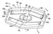
图2为图1所示的跳线连接器的底部透视图;Figure 2 is a bottom perspective view of the jumper connector shown in Figure 1;
图3为图1所示的跳线连接器的剖面图;Fig. 3 is a sectional view of the jumper connector shown in Fig. 1;
图4为图1所示的照明组件的替代跳线连接器的剖面图;4 is a cross-sectional view of an alternative jumper connector to the lighting assembly shown in FIG. 1;
图5为图1所示照明组件的替代跳线连接器的底部透视图;5 is a bottom perspective view of an alternative jumper connector for the lighting assembly shown in FIG. 1;
图6示出了使用图5所示的跳线连接器的替代照明组件;Figure 6 shows an alternative lighting assembly using the jumper connector shown in Figure 5;
图7为图1所示的照明组件的替代跳线连接器的顶部透视图;7 is a top perspective view of an alternative jumper connector for the lighting assembly shown in FIG. 1;
图8是具有图7所示的跳线连接器的一部分照明组件的侧视图;8 is a side view of a portion of a lighting assembly having the jumper connector shown in FIG. 7;
图9是用于图7所示的跳线连接器的导体的透视图;Figure 9 is a perspective view of a conductor for the jumper connector shown in Figure 7;
图10是图7所示的跳线连接器的底部视图;Figure 10 is a bottom view of the jumper connector shown in Figure 7;
图11是具有替代的跳线连接器的一部分照明组件的侧视图;Figure 11 is a side view of a portion of a lighting assembly with an alternative jumper connector;
图12是用于图11所示的跳线连接器的导体的透视图;Figure 12 is a perspective view of a conductor for the jumper connector shown in Figure 11;
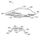
图13是用于照明组件的另一跳线连接器的分解透视图。13 is an exploded perspective view of another jumper connector for a lighting assembly.
具体实施方式Detailed ways
图1示出了包括多个通过跳线连接器24互连的照明部件22的照明组件20。照明部件22沿着部件轴26成排布置以形成照明带。任何数量的照明部件22可以被用来形成照明带。照明部件22通过跳线连接器24串联连接,并且跳线连接器24形成在相邻照明部件22之间传输电能的电路的一部分,这将在下面进行更详细地描述。FIG. 1 shows a
照明部件22被固定在基板28上。在示例性的实施例中,跳线连接器24被用来将照明部件22固定在基板28上。在示出的实施例中,基板28组成吸热器,并且之后会被称为吸热器28。吸热器28散出在运行过程中由照明部件22产生的热量。The
在示例性的实施例中,照明部件22被形成为基本上相同。每个照明部件22包括沿着部件轴26纵向延伸的电路板30。电路板30在相对的第一和第二端32,34之间延伸。电路板30包括基本上面对基板28的内表面36以及面向远离基板28的外表面38。内表面和外表面36,38一般是平面的并且沿着部件轴26在端32,34之间延伸。电路板30包括相对第一和第二边40,42,其在端32,34之间延伸并且在内外表面36,38之间延伸。In the exemplary embodiment,
在示例性的实施例中,电路板30包括位于端32,34上的开口44。每个照明部件22被布置为与相邻照明部件22首尾相连,以使其中的开口44彼此之间被彼此对准以形成共同的开口。该共同的开口具有一个延伸的、不闭合的形状。In the exemplary embodiment,
电路板30包括位于第一端32上的第一配合端部46、位于第二端34上的第二配合端部48,以及在配合端部46,48之间的照明设备安装部分50。一个或多个触垫52可以被设置在每个配合端部46,48上。触垫52沿着电路板30的外表面38裸露。这将在下面进行更详细地描述,当跳线连接器24连接到照明部件22时,触垫52提供同跳线连接器24的电连接。在示出的实施例中,两个导电垫52被设置在每个配合端46,48处。The
一个或多个照明设备54电连接于电路板30。当电能通过跳线连接器24被施加于电路板30时照明设备54运行。可替代地,电路板30可以包括一个或多个电气部件,例如控制器、晶体管、微控制器、电容、电阻等,用于控制提供给照明设备54的功率。在示例性的实施例中,每个照明设备54包括一个或多个发光二极管(LED)56。可替代地,LED56可以被磷材料58或其他材料所围绕以控制照明度。其他类型的照明元件可被用于替代的实施例中。LED56可直接或间接连接于电路板30。LED56可以通过电路板30的迹线或者其他导体被电连接于一个或多个触垫52。当照明部件22被安装于吸热器28上时,由LED56和/或其他连接于电路板30的电气部件产生的热量可由吸热器28散发热量。One or
跳线连接器24即将一对相邻照明部件22机械地固定于基板28上,又将该对相邻照明部件22彼此电连接。电源电路通过跳线连接器24得以建立以将电能从一个照明部件22传送到另一个照明部件22。在组装过程中,跳线连接器24可电连接于同照明部件22同时,或者在同样的组装操作过程中,将照明部件22物理地固定于基板28上。The
跳线连接器24包括介电连接器主体60。在示例性的实施例中,连接器主体60是整体为单件的主体。连接器主体60在相对的第一和第二端部62,64之间延伸。连接器主体60包括一般面向照明部件22的配合表面66以及面向远离照明部件22的外表面68。配合和外表面66,68沿着端部62,64之间的纵向连接器轴70延伸。当跳线连接器24被耦接于照明部件22时,连接器轴70一般平行于部件轴26。连接器主体60包括相对的第一和第二侧边72,74,它们在端部62,64之间延伸并且在配合和外表面66,68之间延伸。连接器主体60包括从其穿过的开口76。开口76可基本上位于端部62,64和侧边72,74的中间。The
紧固件78被用来将跳线连接器24固定于基板28。在示例性的实施例中,紧固件78由带螺纹的紧固件,例如螺丝钉表示,其被接收于基板28上的螺纹孔80中。因而,紧固件78被螺纹耦接到基板28。然而,在替代的实施例中,不同类型的紧固件可以被用来将跳线连接器24固定到基板28上。
在组装过程中,跳线连接器24被置于一对相邻照明部件22的顶上,以使跳线连接器接合相邻照明部件22的端部46,48。相对于跳线连接器24定位紧固件78以将跳线连接器24固定于基板28。紧固件78被移动到跳线连接器24被固定于基板28的固定位置。在示出的实施例中,紧固件78可旋转或者可拧紧到跳线连接器24被牢固地耦接于基板28的固定位置。当跳线连接器24被牢固地耦接于基板28上时,照明部件22同样通过跳线连接器24被固定于基板28。例如,跳线连接器24可以将照明部件22夹在或者另外保持在跳线连接器24的配合表面66和基板的配合表面82之间。在示例性的实施例中,照明部件22的每个端部32,34由不同跳线连接器24保持。跳线连接器24可拆除地耦接于照明部件22,以使跳线连接器24可以被移除从而释放照明部件22从基板28。跳线连接器24可以从照明部件22被释放,以使跳线连接器24和照明部件22均可以反向。跳线连接器24可以在移除紧固件78的单个步骤中从照明部件22被释放。During assembly, the
图2是跳线连接器24的底部透视图,其示出了配合表面66。跳线连接器24包括至少一个由连接器主体60保持的导体84。在示出的实施例中,导体84由电镀材料86形成,该电镀材料电镀由部分的连接器主体60限定的柔性梁88(如图3所示)。梁88(例如在电镀材料86下面的构件)具有在梁88的固定端92和自由端94之间的梁长度90。梁88具有柔韧性并且可以被偏转,例如当同照明部件22相配合时(如图1所示)。在示出的实施例中,所示两个导体部分被表示为在连接器主体60的相应侧边72,74附近延伸,并且所述两个导体部分通过电镀材料86被互连在连接器主体60的中间区域。在替代的实施例中,两个导体部分可以彼此分开并且限定两个分开的导体84。任何数量的导体可以由跳线连接器24所限定和/或保持。FIG. 2 is a bottom perspective view of
导体84在跳线连接器24的第一端部62处的第一配合接合面96和跳线连接器24的第二端部64处的第二配合接合面98之间延伸。在示例性的实施例中,导体84限定了第一和第二配合接合面96,98之间的整体连续的导电元件。在示例性的实施例中,导体84包括位于配合接合面96,98上的按钮100。按钮100从其直接相邻部分向外凸出。按钮100涂敷有电镀材料86并且限定了接合照明部件22的触垫52(如图1所示)的一部分导体84。按钮100突出高于配合表面66以确保合适地电连接于触垫52。The
跳线连接器24包括一个或多个从其延伸的安装凸片102。安装凸片102从配合表面66向外延伸。安装凸片102穿过部分的连接器主体60环绕开口76。在装配过程中,当跳线连接器24相对于照明部件22被定位时,安装凸片102安装在照明部件22的开口44(如图1所示)内。安装凸片102可以被做成一定的尺寸和形状以相对于照明部件22合适地定位跳线连接器24,例如以便对准导体84和触垫52。The
跳线连接器24包括支座104,其从连接器主体60侧边72,74处的配合表面66延伸。支座104具有台肩106,其接合照明部件22的对应侧边40,42(如图1所示)。台肩106可以分开基本上等于照明部件22的宽度的距离108,以使台肩106接合照明部件22的两边40,42。支座104被用来相对于照明部件22来定向或者定位跳线连接器24。The
图3是沿图2所示的线3-3剖开的跳线连接器24的截面图。截面是穿过按钮100得以剖开的。图3示出梁88,其由介电材料做成并且形成为连接器主体60的一部分。按钮100在同一制造过程中与梁88一体形成。按钮100限定由电镀材料86所覆盖的弯曲外表面。FIG. 3 is a cross-sectional view of
电镀材料86覆盖所选择部分的梁88以限定第一和第二配合接合面96,98(如图2所示)之间的导电路径。在示出的实施例中,电镀材料86覆盖梁88的配合表面66,梁88的外表面68和梁88的侧壁110。侧壁110在配合和外表面66,68之间延伸。梁88整个涂覆有电镀材料86。在替代的实施例中,仅有选择部分的梁88可涂敷有电镀材料86。通过涂敷梁88的外表面68和梁88的侧壁110,与梁88的外表面68和侧壁110没有被涂敷的实施例相比,梁88可以被加固。通过加固梁88,梁88具有更大的弹力来抵制和照明部件22装配过程中的变形或偏移(如图1所示)。当同照明部件22相配合时,梁88可以提供足够的接合力。The plating
图4是用于照明组件20(如图1所示)的替代跳线连接器120的截面图,其是通过如图3所示的跳线连接器120的类似部分剖开的。跳线连接器120类似于跳线连接器24(如图3所示)并且包括类似的部分和特征。跳线连接器120和跳线连接器24之间的至少一个不同为跳线连接器120包括仅位于跳线连接器120的梁126的配合表面124上的电镀材料122。梁126的侧壁128和外表面130没有涂覆有电镀材料122。另外,梁126比跳线连接器24的梁88(如图3所示)厚。梁126的厚度同薄一些的梁相比加固了梁126。当仅涂敷配合表面124时需要较少的电镀材料122。4 is a cross-sectional view of an
图5是用于照明组件20(如图1所示)的另一替代跳线连接器140的底部透视图。跳线连接器140包括连接器主体142和导体144。连接器主体142包括配合表面146,导体144设置在配合表面146之上。FIG. 5 is a bottom perspective view of another
导体144由电镀配合表面146的选择部分的电镀材料148表示。在示例性的实施例中,按钮150由导体144和/或连接器主体142所形成。按钮150从配合表面146向外延伸。按钮150是半球形状,但可以在替代的实施例中可具有其他的形状。
连接器主体142包括从其穿过的开口152。安装凸片154被设置为接近于开口152。安装凸片154从配合表面146向外延伸。The
图6示出了使用跳线连接器140的替代照明组件160。照明组件160包括多个照明部件22,其被排列成多于一排162。几排162的照明部件形成多个、平行的照明带。任何数量的照明部件可以被布置在每一排162中,即使只有两个照明部件22被示出在图6的每一排162中。可以设置任何数量的排162的照明部件22,即使仅在图6中示出三排162。FIG. 6 shows an
跳线连接器140被设置在每排162中的相邻照明部件22之间。跳线连接器140产生电力路径以在相邻照明部件22之间传输电能。紧固件164接合跳线连接器140以将跳线连接器140和照明部件22固定到一个或多个基板(未示出)。每一排162的照明部件22和相应的跳线连接器140可以被安装到不同基板。可替代地,多于一排162的照明部件22和相应的跳线连接器140可以被安装到相同基板。基板的尺寸和排162之间的间隔可以影响基板的安装结构。
跳线连接器140通过桥接件166互连,该桥接件在跳线连接器之间延伸并将跳线连接器140彼此连接。在制造过程中,桥接件166可以和多于一个跳线连接器140的连接器主体142形成为一体。可替代地,桥接件166可以在组装过程中被分离地连接到一个或多个跳线连接器140。一旦桥接件166被连接到多个跳线连接器140,跳线连接器140可作为单个单元进行处理。桥接件166将跳线连接器140间距开预定的间距168。可选择地,间距168可以在每一个跳线连接器140之间都相同,并且每一排162的照明部件22也是如此。可替代地,不同长度的桥接件166可以被用于不同跳线连接器140之间以改变跳线连接器140之间的间距168以及因此几排162的照明部件22的间距。The
在示出的实施例中,跳线连接器140具有宽度170,其小于照明部件22的宽度172。因而,跳线连接器140对照明部件22的形状因数没有影响。In the illustrated embodiment, the
跳线连接器140的连接器主体142可以至少部分地能够偏移。当紧固件164被固定于基板以及配合表面146接合照明组件22时,按钮150(如图5所示)接合照明组件22的触垫52(如图1所示)。当紧固件164被拧紧时,连接器主体142可以轻轻地弯曲或者成弓形。当紧固件164被拧紧到固定位置时,跳线连接器140使得两个照明部件22之间电连接并且同时将两个照明部件22固定到基板。在将紧固件164紧固到固定位置上的同一制造步骤中实现了电连接和力学固定。The
图7是用于照明组件20的另一替代跳线连接器200的顶部透视图,其中的一部分示于图7中。跳线连接器200用来将两个相邻照明部件22彼此电连接。跳线连接器200用来将照明部件22固定到基板28(如图1所示)。FIG. 7 is a top perspective view of another
跳线连接器200包括连接器主体202和导体204(在图7中以虚线表示)。连接器主体202在相对的第一和第二端部206,208之间延伸。连接器主体202包括一般面向照明部件22的配合表面210以及面向远离照明部件22的外表面212。连接器主体202包括相对的第一和第二侧边214,216,其在端206,208之间延伸以及在配合和外部表面210,212之间延伸。连接器主体202包括从其穿过的开口218。开口218可以基本上位于端部206,208和侧边214,216的中间。紧固件比如紧固件78(如图1所示)被用来将跳线连接器200固定到基板28。紧固件78接收于开口218中并且接合外表面212以将跳线连接器200固定到基板28。
连接器204由连接器主体202所保持并且在配合表面210处裸露以接合触垫52(以虚线表示)。导体204在端部206,208之间延伸以彼此电连接两个相邻照明部件22。
图8是一部分照明组件20的侧视图,其中跳线连接器200互连相邻的照明部件22。相邻的照明部件22的端部32,34彼此邻接并且跳线连接器200在端部32,34之上大致位于中心。当跳线连接器200通过紧固件78被安装到照明部件22时,配合表面210与照明部件22的外表面38齐平并且倚靠在照明部件22的外表面38上。FIG. 8 is a side view of a portion of a
光锥220在图8中被表示为从照明设备54的中部222发射出来。光锥220具有如图8所示的照明度223的半角,其为从垂直朝向跳线连接器200测量的。照明设备54的中心222被定位成距离照明部件22的端部32为距离224。连接器主体202具有高度226,其被选择成以使跳线连接器200不同光锥220相干涉,并且因而不会不利地阻挡由照明设备54产生的光线。高度226被选择为考虑到连接器主体202和紧固件78之间的任何垫圈230的额外高度228以及位于连接器主体202之上的紧固件78的额外高度232。照度223的半角以及距离224对连接器主体202的高度226具有影响。Cone of
图9是用于跳线连接器200的导体204之一的透视图。导体204包括基底240和两个相对的臂242,244,这两个臂从基底240向下延伸。在示例性的实施例中,臂242,244能够偏斜并且限定了弹簧臂,该弹簧臂提供了在箭头A方向向下的弹力。臂242,244分别限定了导体204的第一和第二配合接合面246,248。在示例性的实施例中,臂242,244被弯曲为接近于其远端以限定靠近臂242,244远端的配合接合面246,248。FIG. 9 is a perspective view of one of the
第一配合接合面246被配置为电接合一个照明部件22(如图7所示)的触垫52(如图7所示)。第二配合接合面246被配置为电接合不同照明部件22的触垫52。因而,导体204在两个不同照明部件22之间产生电路径。第一和第二配合接合面246,248被定位成在基座240之下为距离250。在同照明部件配合的过程中,臂242,244可以朝着由基底240限定的平面向上偏斜。The
在示例性的实施例中,导体204从坯料压模然后通过使部分的导体204弯曲而形成为最终的形状。In the exemplary embodiment,
图10是跳线连接器200的底部视图,其示出了固定在连接器主体202之中的两个导体204。尽管示出了两个导体204,但是认识到可采用任何数量的导体。另外,尽管导体204彼此分开,但是认识到导体204可以彼此之间接合或者通过其中的另一些导电元件彼此连接。FIG. 10 is a bottom view of
连接器主体202包括在其中形成的通道260。导体204固定于通道260中,以使配合接合面246,248被设置为接近于配合表面210。在示例性的实施例中,导体204从通道260稍微地伸出,以使配合接合面246,248暴露于配合表面210的底部的下面,用于与照明部件22(如图7所示)的触垫52(如图7所示)接合。
图11是用于照明组件20的另一替代跳线连接器300的一部分的侧视图,其中的一部分示于图11中。跳线连接器300用来彼此电连接两个相邻照明部件22。跳线连接器300用来将两个照明部件22固定到基板28(如图1所示)。FIG. 11 is a side view of a portion of another
跳线连接器300包括连接器主体302和一个或多个导体304(在图11中以虚线示出)。连接器主体302在相对的第一和第二端306,308之间延伸。连接器主体302包括一般面对照明部件22的配合表面310和面向远离照明部件22的外表面312。紧固件例如紧固件78(如图1所示)被用来将跳线连接器300固定于基板28。紧固件78接合外表面312来将跳线连接器300固定于基板28。
导体304被固定于形成在连接器主体302中的专用通道之内(未示出)。这些通道在配合表面310开口并且在装配过程中导体304通过配合表面310装入通道内。保持肋314(在图11中以虚线示出)部分延伸到通道中并且接合导体304来保持通道中的导体304。导体304被固定于连接器主体302之中,以使导体304在配合表面310处裸露从而接合触垫52(以虚线示出)。导体304在端306,308之间延伸以将两个相邻的照明部件22彼此电连接。The
图12是用于跳线连接器300(如图11所示)的导体304之一的透视图。导体304包括基底340和两个相对臂342,344,该两个臂从基底340往下延伸。在示例性的实施例中,臂342,344能够偏斜并且限定了弹簧臂,该弹簧臂提供箭头B方向的向下的弹力。臂342,344分别限定了导体304的第一和第二配合接合面346,348。在示例性的实施例中,第一和第二配合接合面346,348设置在臂342,344的远端。第一配合接合面346被配置为电接合一个照明部件22(如图11所示)的触垫52(如图11所示)。第二配合接合面348被配置为电接合不同照明部件22的触垫52。因而,导体304在两个不同照明部件22之间产生电路径。FIG. 12 is a perspective view of one of the
在示例性的实施例中,导体304通过压模步骤制成。导体的形状由现有材料坯件压模而成。不需要成形步骤将导体304从压模形状成形为不同的形状。In the exemplary embodiment,
图13是用于照明组件20(如图1所示)的另一跳线连接器400的分解透视图。跳线连接器400用来将两个相邻照明部件22彼此电连接(如图1所示)。跳线连接器400用来将两个照明部件22固定到基板28(如图1所示)。FIG. 13 is an exploded perspective view of another
跳线连接器400包括连接器主体402和一个或多个导体404(在图11中以虚线示出)。连接器主体402在两个相对的第一和第二端406,408之间延伸。连接器主体402包括一般面向照明部件22的配合表面410以及面向远离照明部件22的外表面412。紧固件比如紧固件78(如图1所示)被用来将跳线连接器400固定到基板28。
导体404被保持于形成在连接器主体402中的专用通道414内。这些通道414在配合表面410开口并且在装配过程中导体404通过配合表面410装入通道414中。保持肋416部分地延伸到通道414中并且接合从导体404延伸的指状部418来将导体404保持于通道414内。导体404被保持于连接器主体402之中,以使导体404在配合表面410处裸露从而接合触垫52(如图1所示)。导体404在端406,408之间延伸以将两个相邻照明部件22彼此电连接。The
导体404包括基底440和两个相对的臂442,444,该两个臂从基底440向下延伸。在示例性的实施例中,臂442,444能够偏斜并且限定了提供向下的弹力的弹簧臂。臂442,444分别限定导体404的第一和第二配合接合面446,448。在示例性的实施例中,第一和第二配合接合面446,448被设置为接近或者位于臂442,444的远端。第一配合接合面446被配置为与一个照明部件22的触垫52电接合。第二配合接合面448被配置为与另一照明部件22的触垫52电接合。这样,导体404在两个不同照明部件22之间产生电路径。The
Claims (6)
Translated fromChineseApplications Claiming Priority (2)
| Application Number | Priority Date | Filing Date | Title |
|---|---|---|---|
| US12/366,819 | 2009-02-06 | ||
| US12/366,819US7892022B2 (en) | 2009-02-06 | 2009-02-06 | Jumper connector for a lighting assembly |
Publications (2)
| Publication Number | Publication Date |
|---|---|
| CN101852413A CN101852413A (en) | 2010-10-06 |
| CN101852413Btrue CN101852413B (en) | 2013-10-09 |
Family
ID=41718462
Family Applications (1)
| Application Number | Title | Priority Date | Filing Date |
|---|---|---|---|
| CN2010101729345AActiveCN101852413B (en) | 2009-02-06 | 2010-02-08 | Jumper connectors for lighting components |
Country Status (5)
| Country | Link |
|---|---|
| US (1) | US7892022B2 (en) |
| EP (1) | EP2216858B1 (en) |
| JP (1) | JP5354795B2 (en) |
| CN (1) | CN101852413B (en) |
| TW (1) | TWI530640B (en) |
Families Citing this family (35)
| Publication number | Priority date | Publication date | Assignee | Title |
|---|---|---|---|---|
| US9772099B2 (en) | 2009-10-05 | 2017-09-26 | Lighting Science Group Corporation | Low-profile lighting device and attachment members and kit comprising same |
| US9581756B2 (en) | 2009-10-05 | 2017-02-28 | Lighting Science Group Corporation | Light guide for low profile luminaire |
| US8672518B2 (en) | 2009-10-05 | 2014-03-18 | Lighting Science Group Corporation | Low profile light and accessory kit for the same |
| USD797980S1 (en) | 2010-05-06 | 2017-09-19 | Lighting Science Group Corporation | Low profile light |
| DE102011005047B3 (en)* | 2011-03-03 | 2012-09-06 | Osram Ag | lighting device |
| JP5463478B2 (en)* | 2011-03-04 | 2014-04-09 | シーシーエス株式会社 | Line light irradiation device |
| US9146027B2 (en) | 2011-04-08 | 2015-09-29 | Ideal Industries, Inc. | Device for holding a source of LED light |
| CN102263330A (en)* | 2011-06-08 | 2011-11-30 | 苏州东山精密制造股份有限公司 | LED (Light-emitting Diode) lamp strip connector |
| DE102011084814A1 (en)* | 2011-10-19 | 2013-04-25 | Osram Opto Semiconductors Gmbh | MOUNTING ELEMENT FOR HOLDING AT LEAST ONE FLAT LIGHT LAMP, SET OF A MULTIPLE OF VERSIONS AND A MULTIPLE OF LONG-SLIPED HOLDING BODIES AND LUMINAIRE |
| WO2013063475A1 (en)* | 2011-10-26 | 2013-05-02 | Amerlux, Llc | Led connector |
| EP2792026B1 (en)* | 2011-12-14 | 2017-08-23 | Ideal Industries Inc. | Electrical connectors for use with printed circuit boards |
| EP2803117B1 (en)* | 2012-01-13 | 2016-11-23 | OSRAM GmbH | Method of producing flexible electrical cords and connector therefor |
| DE102012102055A1 (en)* | 2012-03-12 | 2013-09-12 | Ept Gmbh | Connector i.e. mechanical support, for connecting printed circuit boards in coplanar arrangement, has base body comprising projection for positively intervention into intermediate space between printed circuit boards |
| DE102012208249A1 (en)* | 2012-05-16 | 2013-11-21 | Osram Gmbh | Connection module, power supply module and connection set for light strips |
| WO2013192418A2 (en) | 2012-06-21 | 2013-12-27 | Ideal Industries, Inc. | Electrical connectors for use with printed circuit boards |
| EP2685151A3 (en)* | 2012-07-09 | 2017-11-15 | Panasonic Intellectual Property Management Co., Ltd. | Illumination device |
| US9065187B2 (en)* | 2012-10-26 | 2015-06-23 | Amerlux Llc | LED connector |
| CN103411181A (en)* | 2013-07-01 | 2013-11-27 | 广德润视机电有限公司 | Device for fixing LED lamp on panel lamp |
| CN103438408B (en)* | 2013-07-29 | 2016-08-17 | 南京中电熊猫液晶显示科技有限公司 | A kind of LED lamp bar adapter and backlight module |
| DE102013219333A1 (en)* | 2013-09-25 | 2015-03-26 | Osram Gmbh | LED light |
| CN103557451B (en)* | 2013-10-12 | 2015-08-26 | 王丽娜 | LED illumination lamp |
| US9293848B2 (en)* | 2014-05-29 | 2016-03-22 | Ideal Industries, Inc. | Electrical connector for use with printed circuit boards |
| US9520703B2 (en)* | 2014-07-31 | 2016-12-13 | Power Distribution, Inc. | Electrical busway splice connector |
| FR3024599B1 (en)* | 2014-08-04 | 2016-08-05 | Abb France | JUNCTION BLOCK FOR GROUNDING |
| US9942992B2 (en)* | 2014-09-10 | 2018-04-10 | Amerlux Llc | Methods for assembling LED connector board |
| CN105119071A (en)* | 2015-09-30 | 2015-12-02 | 东莞市昶通通讯科技有限公司 | Electrical connector and its device and assembly method |
| CN113090968B (en)* | 2015-10-26 | 2023-06-23 | J·P·霍夫曼 | LED Light Linear Strips, Mounting Structures and Clip Assemblies |
| CN108700284B (en)* | 2016-01-11 | 2021-01-01 | 莱德爱邦德国际股份有限公司 | Power supply module |
| FR3048559B1 (en)* | 2016-03-04 | 2018-03-09 | Schneider Electric Industries Sas | ELECTRICAL STRUCTURE FOR CONNECTING A BAR CONDUCTIVE TO AN ELECTRICAL COMPONENT |
| DE102016107897B4 (en)* | 2016-04-28 | 2020-06-18 | Wago Verwaltungsgesellschaft Mbh | Circuit board connector and circuit board arrangement thus formed |
| CN110867693B (en)* | 2018-08-28 | 2021-03-30 | 光宝电子(广州)有限公司 | Jumper and power distribution device |
| US11396985B2 (en) | 2019-09-06 | 2022-07-26 | Illumina, Inc. | PCB interconnect scheme for co-planar LED strips |
| CN113382534B (en)* | 2020-03-10 | 2022-10-25 | 英业达科技有限公司 | Circuit board fixing structure |
| WO2022210423A1 (en)* | 2021-03-30 | 2022-10-06 | 株式会社オートネットワーク技術研究所 | Terminal module |
| US20240305052A1 (en)* | 2023-03-06 | 2024-09-12 | Juniper Design Group Inc. | Low-profile track system |
Citations (3)
| Publication number | Priority date | Publication date | Assignee | Title |
|---|---|---|---|---|
| US6299469B1 (en)* | 1999-04-22 | 2001-10-09 | Visteon Global Technologies, Inc. | Flexible circuit board splice clamp |
| US6659623B2 (en)* | 2000-05-05 | 2003-12-09 | Thales Optronics (Taunton) Ltd. | Illumination system |
| CN201173401Y (en)* | 2008-04-09 | 2008-12-31 | 陈雅惠 | Luminous body cascading package structure |
Family Cites Families (18)
| Publication number | Priority date | Publication date | Assignee | Title |
|---|---|---|---|---|
| FR1222758A (en)* | 1959-01-22 | 1960-06-13 | Lepaute Henry S Ets | Improvements to electrical connection devices |
| JP2512784Y2 (en)* | 1990-09-20 | 1996-10-02 | 川崎重工業株式会社 | Internal unit wiring structure |
| DE29810555U1 (en)* | 1998-06-16 | 1998-09-10 | Phoenix Contact GmbH & Co, 32825 Blomberg | Electrical slide valve with anti-rotation device |
| US6428189B1 (en)* | 2000-03-31 | 2002-08-06 | Relume Corporation | L.E.D. thermal management |
| US6641284B2 (en)* | 2002-02-21 | 2003-11-04 | Whelen Engineering Company, Inc. | LED light assembly |
| US7273987B2 (en)* | 2002-03-21 | 2007-09-25 | General Electric Company | Flexible interconnect structures for electrical devices and light sources incorporating the same |
| US7021946B2 (en)* | 2002-04-19 | 2006-04-04 | Citizens Electronics Co., Ltd. | Connector integrated with a LED element |
| US6802626B2 (en)* | 2002-05-31 | 2004-10-12 | Lighting World Inc. | Track lighting system including lamp clips with separate locking and connection means |
| US6666713B1 (en)* | 2002-07-19 | 2003-12-23 | Ronald D. Norvelle | Ganged receptacle fixture apparatus |
| US6882111B2 (en)* | 2003-07-09 | 2005-04-19 | Tir Systems Ltd. | Strip lighting system incorporating light emitting devices |
| US7165863B1 (en)* | 2004-09-23 | 2007-01-23 | Pricilla G. Thomas | Illumination system |
| KR100684743B1 (en)* | 2004-10-28 | 2007-02-20 | 삼성에스디아이 주식회사 | Secondary battery module |
| JP2006351327A (en)* | 2005-06-15 | 2006-12-28 | Alps Electric Co Ltd | Connection structure of members, its manufacturing method, and electronic equipment having connection structure of members |
| US7311420B2 (en)* | 2005-08-22 | 2007-12-25 | Avago Technologies Ecbuip Pte Ltd | Opto-electronic package, and methods and systems for making and using same |
| US7364346B2 (en)* | 2005-09-06 | 2008-04-29 | The L.D. Kichler Co. | Low voltage track lighting assembly and system |
| EP1928026A1 (en)* | 2006-11-30 | 2008-06-04 | Toshiba Lighting & Technology Corporation | Illumination device with semiconductor light-emitting elements |
| KR100818510B1 (en)* | 2007-01-16 | 2008-03-31 | 삼성전기주식회사 | PC connector for LCD and chassis using the same |
| US7815341B2 (en)* | 2007-02-14 | 2010-10-19 | Permlight Products, Inc. | Strip illumination device |
- 2009
- 2009-02-06USUS12/366,819patent/US7892022B2/enactiveActive
- 2010
- 2010-01-29JPJP2010018761Apatent/JP5354795B2/ennot_activeExpired - Fee Related
- 2010-02-01EPEP10152333.0Apatent/EP2216858B1/ennot_activeNot-in-force
- 2010-02-01TWTW099102776Apatent/TWI530640B/enactive
- 2010-02-08CNCN2010101729345Apatent/CN101852413B/enactiveActive
Patent Citations (3)
| Publication number | Priority date | Publication date | Assignee | Title |
|---|---|---|---|---|
| US6299469B1 (en)* | 1999-04-22 | 2001-10-09 | Visteon Global Technologies, Inc. | Flexible circuit board splice clamp |
| US6659623B2 (en)* | 2000-05-05 | 2003-12-09 | Thales Optronics (Taunton) Ltd. | Illumination system |
| CN201173401Y (en)* | 2008-04-09 | 2008-12-31 | 陈雅惠 | Luminous body cascading package structure |
Also Published As
| Publication number | Publication date |
|---|---|
| EP2216858A3 (en) | 2013-12-18 |
| TWI530640B (en) | 2016-04-21 |
| JP5354795B2 (en) | 2013-11-27 |
| EP2216858B1 (en) | 2018-03-28 |
| US7892022B2 (en) | 2011-02-22 |
| US20100203757A1 (en) | 2010-08-12 |
| TW201033525A (en) | 2010-09-16 |
| JP2010182674A (en) | 2010-08-19 |
| CN101852413A (en) | 2010-10-06 |
| EP2216858A2 (en) | 2010-08-11 |
Similar Documents
| Publication | Publication Date | Title |
|---|---|---|
| CN101852413B (en) | Jumper connectors for lighting components | |
| CN102159885B (en) | Led interconnect assembly | |
| JP5594892B2 (en) | Socket assembly having thermal management structure | |
| EP2142842B1 (en) | Led connector assembly with heat sink | |
| US8220956B2 (en) | LED lamp | |
| JP5669188B2 (en) | LED lighting assembly | |
| US8905577B2 (en) | Lamp housing with clamping lens | |
| US7728231B2 (en) | Light emitting module, lighting device, and display device | |
| JP6285035B2 (en) | LED socket assembly | |
| JP4479839B2 (en) | Package and semiconductor device | |
| JP6041629B2 (en) | LED socket assembly | |
| KR20130056809A (en) | Led connector and lighting equipment | |
| KR101378697B1 (en) | Led socket assembly | |
| KR20130059871A (en) | Light emitting modul | |
| JP5713713B2 (en) | LED connector | |
| TW201324883A (en) | Semiconductor light-emitting element mounting module, and semiconductor light-emitting element module | |
| KR101177713B1 (en) | Module For Mounting LED And LED Module | |
| CN110566832B (en) | Light source module | |
| JP3139079U (en) | LED unit and LED module | |
| TW201243225A (en) | Light-emitting device with spring-loaded LED-holder |
Legal Events
| Date | Code | Title | Description |
|---|---|---|---|
| C06 | Publication | ||
| PB01 | Publication | ||
| C10 | Entry into substantive examination | ||
| SE01 | Entry into force of request for substantive examination | ||
| C14 | Grant of patent or utility model | ||
| GR01 | Patent grant | ||
| CP01 | Change in the name or title of a patent holder | Address after:American Pennsylvania Patentee after:TE CONNECTIVITY Corp. Address before:American Pennsylvania Patentee before:Tyco Electronics Corp. | |
| CP01 | Change in the name or title of a patent holder | ||
| TR01 | Transfer of patent right | Effective date of registration:20250709 Address after:Schaffhausen Patentee after:Tailian Service Co.,Ltd. Country or region after:Switzerland Address before:Pennsylvania, USA Patentee before:TE CONNECTIVITY Corp. Country or region before:U.S.A. | |
| TR01 | Transfer of patent right | ||
| TR01 | Transfer of patent right | Effective date of registration:20250901 Address after:Schaffhausen Patentee after:Tailian solutions Co.,Ltd. Country or region after:Switzerland Address before:Schaffhausen Patentee before:Tailian Service Co.,Ltd. Country or region before:Switzerland | |
| TR01 | Transfer of patent right |