CN101850468B - Resistance welding method and resistance welding apparatus - Google Patents
Resistance welding method and resistance welding apparatusDownload PDFInfo
- Publication number
- CN101850468B CN101850468BCN201010159444.1ACN201010159444ACN101850468BCN 101850468 BCN101850468 BCN 101850468BCN 201010159444 ACN201010159444 ACN 201010159444ACN 101850468 BCN101850468 BCN 101850468B
- Authority
- CN
- China
- Prior art keywords
- electrode
- welding
- workpiece
- thinnest
- tributary
- Prior art date
- Legal status (The legal status is an assumption and is not a legal conclusion. Google has not performed a legal analysis and makes no representation as to the accuracy of the status listed.)
- Active
Links
Images


Classifications
- B—PERFORMING OPERATIONS; TRANSPORTING
- B23—MACHINE TOOLS; METAL-WORKING NOT OTHERWISE PROVIDED FOR
- B23K—SOLDERING OR UNSOLDERING; WELDING; CLADDING OR PLATING BY SOLDERING OR WELDING; CUTTING BY APPLYING HEAT LOCALLY, e.g. FLAME CUTTING; WORKING BY LASER BEAM
- B23K11/00—Resistance welding; Severing by resistance heating
- B23K11/10—Spot welding; Stitch welding
- B23K11/11—Spot welding
- B23K11/115—Spot welding by means of two electrodes placed opposite one another on both sides of the welded parts
- B—PERFORMING OPERATIONS; TRANSPORTING
- B23—MACHINE TOOLS; METAL-WORKING NOT OTHERWISE PROVIDED FOR
- B23K—SOLDERING OR UNSOLDERING; WELDING; CLADDING OR PLATING BY SOLDERING OR WELDING; CUTTING BY APPLYING HEAT LOCALLY, e.g. FLAME CUTTING; WORKING BY LASER BEAM
- B23K11/00—Resistance welding; Severing by resistance heating
- B23K11/002—Resistance welding; Severing by resistance heating specially adapted for particular articles or work
- B23K11/0026—Welding of thin articles
- B—PERFORMING OPERATIONS; TRANSPORTING
- B23—MACHINE TOOLS; METAL-WORKING NOT OTHERWISE PROVIDED FOR
- B23K—SOLDERING OR UNSOLDERING; WELDING; CLADDING OR PLATING BY SOLDERING OR WELDING; CUTTING BY APPLYING HEAT LOCALLY, e.g. FLAME CUTTING; WORKING BY LASER BEAM
- B23K11/00—Resistance welding; Severing by resistance heating
- B23K11/30—Features relating to electrodes
Landscapes
- Engineering & Computer Science (AREA)
- Mechanical Engineering (AREA)
- Resistance Welding (AREA)
Abstract
Description
Translated fromChinese技术领域technical field
本发明涉及一种电阻焊方法和电阻焊装置,用于电阻焊由三个或更多个工件构成的堆叠组件,该堆叠组件包括设置在该堆叠组件最外侧的最薄工件。The present invention relates to a resistance welding method and resistance welding apparatus for resistance welding a stacked assembly composed of three or more workpieces, the stacked assembly including the thinnest workpiece disposed on the outermost side of the stacked assembly.
背景技术Background technique
一种已知的将多个金属板相互连接的工艺是电阻焊工艺,在该工艺中,金属板堆叠成堆叠组件。接着,在一组焊接电极夹住并对堆叠组件施压后,电流在焊接电极间通过,以融化金属板的靠近接触表面的区域。凝固后,融化区变成称为熔核的固相。在一些情况下,用这样的电阻焊工艺将三个或更多个金属板连接到一起。One known process for interconnecting multiple metal sheets is the resistance welding process in which the metal sheets are stacked to form a stacked assembly. Next, after a set of welding electrodes clamps and presses the stacked assembly, an electric current is passed between the welding electrodes to melt the area of the metal sheet near the contact surface. After solidification, the molten region becomes a solid phase called the nugget. In some cases, three or more metal plates are joined together using such a resistance welding process.
待电阻焊的金属板或工件的厚度不一定彼此相同,在多数情况下相互不同。因此,金属板倾向于包括具有最薄厚度的工件(以下称为“最薄工件”)。The thicknesses of the metal sheets or workpieces to be resistance welded are not necessarily the same as each other, and in many cases are different from each other. Therefore, the metal plate tends to include the workpiece with the thinnest thickness (hereinafter referred to as "thinnest workpiece").
如果金属板的堆叠组件经电阻焊具有设置在该堆叠组件最外侧的最薄工件,那么在最薄工件和与其相邻的工件之间形成的熔核可能不会充分地生长。熔核不充分生长的原因据认为是基于这样的事实:由于最薄工件的厚度是最小的而它的特定电阻是最小的,因而最薄工件不能产生足够量的焦耳热。If a stack assembly of metal plates is resistance welded with the thinnest work disposed on the outermost side of the stack assembly, a nugget formed between the thinnest work and a work adjacent thereto may not grow sufficiently. The reason for the insufficient growth of the nugget is considered to be based on the fact that the thinnest workpiece cannot generate a sufficient amount of Joule heat because its thickness is the smallest and its specific resistance is the smallest.
为了使靠近最薄工件的熔核充分生长,可以通过加大在焊接电极间流过的电流来增加在最薄工件中产生的焦耳热。然而,在此情况下,大电流倾向于流过具有更大厚度的工件,因而,这样加大的电流倾向于过度融化工件,从而产生金属颗粒散落并导致飞溅(sputtering)。In order to fully grow the nugget close to the thinnest workpiece, the Joule heat generated in the thinnest workpiece can be increased by increasing the current flowing between the welding electrodes. In this case, however, a large current tends to flow through a workpiece having a greater thickness, and thus such an increased current tends to melt the workpiece excessively, thereby causing scattering of metal particles and causing sputtering.
或者,可以增加施加电流的时间长度。但是,在此情况下,也难于在最薄工件中产生足够的焦耳热。另外,不利的是,更长的焊接时间导致焊接效率降低。Alternatively, the length of time the current is applied can be increased. However, also in this case, it is difficult to generate sufficient Joule heat in the thinnest workpiece. In addition, disadvantageously, longer welding times lead to lower welding efficiency.
考虑到以上难点,日本公开专利文件No.2005-262259提出用于电阻焊由三个或更多个金属板构成的堆叠组件的两阶段电阻点焊工艺,最薄工件设置在该堆叠组件的最外侧。两阶段电阻点焊工艺包括第一阶段和第二阶段,在第一阶段,堆叠组件上的压力减小,大电流通过堆叠组件,而在第二阶段,该压力调到大于第一阶段的压力的水平,在第二阶段期间,等于或小于第一阶段电流的电流通过堆叠组件的时间比第一阶段电流通过的时间长。In consideration of the above difficulties, Japanese Laid-Open Patent Document No. 2005-262259 proposes a two-stage resistance spot welding process for resistance welding a stacked assembly consisting of three or more metal plates. The thinnest workpiece is placed at the thinnest of the stacked assembly. outside. The two-stage resistance spot welding process includes a first stage where the pressure on the stack is reduced and a high current is passed through the stack, and a second stage where the pressure is adjusted to be greater than that of the first stage During the second stage, the current equal to or less than the first stage current passes through the stack assembly for a longer time than the first stage current.
根据日本公开专利文件No.2005-262259披露的电阻点焊工艺是有效的,易于产生具有需要尺寸的熔核的点焊接头,而不会增加额外的工艺步骤,不会造成飞溅。The resistance spot welding process disclosed in Japanese Laid-Open Patent Document No. 2005-262259 is efficient and easy to produce a spot welded joint with a nugget of required size without adding additional process steps and without causing spatter.
尽管如此,本领域仍期望采用比日本公开专利文件No.2005-262259披露的工艺更得意的控制工艺来增加焊接头的结合强度。Nevertheless, it is still desired in the art to increase the bonding strength of the welded joint using a more controlled process than the process disclosed in Japanese Laid-Open Patent Document No. 2005-262259.
发明内容Contents of the invention
本发明总的目的是提供一种电阻焊方法,通过该方法,简单的控制工艺能够使堆叠组件最外侧的最薄工件和邻近该最薄工件设置的工件之间的熔核充分地生长。A general object of the present invention is to provide a resistance welding method by which a simple control process enables sufficient growth of a nugget between the thinnest workpiece on the outermost side of a stack assembly and workpieces disposed adjacent to the thinnest workpiece.
本发明主要目的是提供一种电阻焊方法,该方法消除造成飞溅的趋势。The main object of the present invention is to provide a method of resistance welding which eliminates the tendency to cause spatter.
本发明另一个目的是提供一种电阻焊装置,该装置能够执行如上所述的电阻焊方法。Another object of the present invention is to provide a resistance welding apparatus capable of performing the resistance welding method as described above.
根据本发明的一个方面,提供一种电阻焊堆叠组件的方法,该堆叠组件由至少三个工件构成,包括设置在该堆叠组件最外侧的具有最小厚度的最薄工件,所述方法包括如下步骤:将堆叠组件夹在第一焊接电极和第二焊接电极之间使得第一焊接电极保持为抵靠最薄工件,并将支流电极保持为抵靠最薄工件,所述支流电极具有与第一焊接电极相反的极性;以及,使电流在第一焊接电极和第二焊接电极之间通过以电阻焊堆叠组件,并且还使分支电流从第一焊接电极流到支流电极或者从支流电极流到第一焊接电极。According to one aspect of the present invention, there is provided a method of resistance welding a stacked assembly, the stacked assembly is composed of at least three workpieces, including the thinnest workpiece with the smallest thickness disposed on the outermost side of the stacked assembly, the method comprising the following steps : Sandwiching the stack assembly between a first welding electrode and a second welding electrode such that the first welding electrode is held against the thinnest workpiece and a tributary electrode is held against the thinnest workpiece, said tributary electrode having the same opposite polarity of the welding electrodes; and, passing current between the first welding electrode and the second welding electrode to resistance weld the stacked assembly, and also passing a branch current from the first welding electrode to the branch electrode or from the branch electrode to first welding electrode.
根据上述方法,除了将堆叠组件夹在第一焊接电极和第二焊接电极之间外,当电流在第一焊接电极和第二焊接电极之间通过时,支流电极保持为抵靠最薄工件。由于第一焊接电极和支流电极保持为抵靠最薄工件并具有彼此相反的极性,分支电流从第一焊接电极流到支流电极,或从支流电极流到第一焊接电极。当分支电流流过最薄工件时,最薄工件与其相邻的工件之间的界面受到充分加热。According to the method described above, in addition to sandwiching the stack assembly between the first welding electrode and the second welding electrode, the branch electrode is held against the thinnest workpiece when current is passed between the first welding electrode and the second welding electrode. Since the first welding electrode and the branch electrode are held against the thinnest workpiece and have opposite polarities to each other, a branch current flows from the first welding electrode to the branch electrode or from the branch electrode to the first welding electrode. When the branch current flows through the thinnest workpiece, the interface between the thinnest workpiece and its adjacent workpieces is sufficiently heated.
由分支电流如此加热的界面获得了在其中的足够大的熔核,由此在界面上产生了具有优秀连接强度的接头。The interface thus heated by the branch current acquires a sufficiently large nugget therein, whereby a joint with excellent connection strength is produced at the interface.
流过其余工件的电流比普通电阻焊工艺中的小,普通电阻焊工艺只利用第一焊接电极和第二焊接电极将堆叠组件夹在中间。因而,这些工件消除了造成飞溅的趋势,同时,在界面上获得的熔核在尺寸方面长得足够大。The current flowing through the remaining workpieces is less than in conventional resistance welding processes, which only utilize the first and second welding electrodes to sandwich the stacked assembly. These workpieces thus eliminate the tendency to cause spatter, while at the same time the nugget obtained at the interface grows sufficiently large in size.
这样,使足够大的熔核在位于堆叠组件最外侧的最薄工件和与最薄工件相邻的工件之间长大是可能的,同时,能够消除造成飞溅的趋势。In this way, it is possible to grow a nugget of sufficient size between the thinnest workpiece on the outermost side of the stack and the workpieces adjacent to the thinnest workpiece, while at the same time eliminating the tendency to cause spatter.
如果熔核没有在其余工件之间的界面中形成,或者如果熔核没有在其余工件之间的界面中充分长大,那么可以在电流持续通过第一焊接电极和第二焊接电极之间时,仅仅使支流电极与最薄工件间隔开,或者使支流电极和电源之间的电路断开。可以通过断开电连接在支流电极和电源之间的开关来切断支流电极和电源之间的电路。If the nugget does not form in the interface between the remaining workpieces, or if the nugget does not grow sufficiently in the interface between the remaining workpieces, then the current may be continuously passed between the first welding electrode and the second welding electrode, Space only the tributary electrode from the thinnest workpiece, or disconnect the circuit between the tributary electrode and the power source. The electrical circuit between the tributary electrode and the power source can be interrupted by opening a switch electrically connected between the tributary electrode and the power source.
当支流电极与最薄工件间隔开时,或者当支流电极和电源之间的电路断开时,分支电流消除,从而在最薄工件中产生的焦耳热的量减少。结果,在最薄工件和与其相邻的工件之间形成的熔核以减小的速率生长。流过其余工件的电流增加,因而在其余工件中产生的焦耳热的量增加。因此,熔核在其余工件之间的界面形成并在尺寸上长得足够大。When the shunt electrode is spaced from the thinnest workpiece, or when the electrical circuit between the shunt electrode and the power source is broken, the shunt current is eliminated, thereby reducing the amount of Joule heat generated in the thinnest workpiece. As a result, the nugget formed between the thinnest workpiece and its neighbors grows at a reduced rate. The current flowing through the remaining workpieces increases, and thus the amount of Joule heat generated in the remaining workpieces increases. Therefore, a nugget is formed at the interface between the remaining workpieces and grows sufficiently large in size.
根据本发明的另一方面,还提供一种电阻焊堆叠组件的装置,该堆叠组件由至少三个工件构成,包括设置在该堆叠组件最外侧的具有最小厚度的最薄工件,所述装置包括:第一焊接电极,保持为抵靠所述最薄工件;第二焊接电极,与第一焊接电极协作将堆叠组件夹在中间;和支流电极,保持为抵靠所述最薄工件,该支流电极具有与第一焊接电极相反的极性。在该装置中,第一焊接电极和第二焊接电极将堆叠组件夹在它们之间以电阻焊该堆叠组件,当电流在第一焊接电极和第二焊接电极之间通过时,分支电流从第一焊接电极流到支流电极或者从支流电极流到第一焊接电极。According to another aspect of the present invention, there is also provided an apparatus for resistance welding a stacked assembly, the stacked assembly is composed of at least three workpieces, including the thinnest workpiece with the smallest thickness disposed on the outermost side of the stacked assembly, the apparatus includes : a first welding electrode held against said thinnest workpiece; a second welding electrode cooperating with the first welding electrode to sandwich the stack assembly; and a branch electrode held against said thinnest work piece, the tributary The electrode has an opposite polarity to the first welding electrode. In this device, the first welding electrode and the second welding electrode sandwich the stacked assembly between them to resistance weld the stacked assembly, and when the current passes between the first welding electrode and the second welding electrode, a branch current flows from the first welding electrode to the second welding electrode. A welding electrode flows to the branch electrode or flows from the branch electrode to the first welding electrode.
当该装置电阻焊堆叠组件时,用于充分加热最薄工件和与其相邻的工件之间的界面的分支电流从第一焊接电极流过最薄工件到支流电极,或者从支流电极流到第一焊接电极。结果,在该界面中,熔核在尺寸上长得足够大。When the device resistively welds a stacked assembly, a branch current for sufficiently heating the interface between the thinnest workpiece and its adjacent workpiece flows from the first welding electrode through the thinnest workpiece to the branch electrode, or from the branch electrode to the first welding electrode. A welding electrode. As a result, in this interface, the nugget grows sufficiently large in size.
为了产生分支电流,该装置只需要额外包括支流电极和用于移位支流电极的移位机构。因而,该装置不会因增加支流电极和移位机构而导致在结构上过度复杂。而且,控制该装置的工艺相对简单。In order to generate a branch current, the device only needs to additionally comprise a branch electrode and a displacement mechanism for displacing the branch electrode. Therefore, the device will not be overly complicated in structure due to the addition of branch electrodes and displacement mechanisms. Moreover, the process of controlling the device is relatively simple.
支流电极可以与第一焊接电极一致地(in unison)通过用于移位第一焊接电极的机构移位而靠近或远离最薄工件。然而,更优选地是移位机构只用于移位支流电极靠近或远离最薄工件,使得能够分别控制最薄工件和与其相邻的工件之间的界面的加热和其余工件之间的界面的加热。The branch electrode may be displaced in unison with the first welding electrode by the mechanism for displacing the first welding electrode closer to or further away from the thinnest workpiece. However, it is more preferred that the shifting mechanism is only used to shift the tributary electrode closer to or away from the thinnest workpiece, so that the heating of the interface between the thinnest workpiece and its adjacent workpiece and the heating of the interface between the remaining workpieces can be controlled respectively. heating.
或者,开关可以电连接在支流电极和电源之间,以连接或断开支流电极和电源之间的电路。该开关可以从闭合状态切换到断开状态,反之亦然,以便分别控制最薄工件和与其相邻的工件之间的界面的加热和其余工件之间的界面的加热。Alternatively, a switch may be electrically connected between the tributary electrode and the power source to connect or break the circuit between the tributary electrode and the power source. The switch can be switched from a closed state to an open state and vice versa to control the heating of the interface between the thinnest workpiece and its adjacent workpieces and the heating of the interfaces between the remaining workpieces, respectively.
支流电极优选地为环状形状,设置成与第一焊接电极呈围绕的关系。环状支流电极使分支电流均匀地流过最薄工件。因而,最薄工件和与其相邻的工件之间的界面被均匀加热,从而促进熔核形成和长大到足够的尺寸。The branch electrode is preferably annular in shape and is arranged in surrounding relationship with the first welding electrode. The ring-shaped branch current electrode makes the branch current flow evenly through the thinnest workpiece. Thus, the interface between the thinnest workpiece and its neighbors is uniformly heated, thereby promoting nugget formation and growth to a sufficient size.
通过下面的说明,本发明的上述和其它的目的、特征和优势会变得更加清楚,下面的说明结合用于显示作为说明例子的本发明优选实施例的附图来进行。The above and other objects, features and advantages of the present invention will become more apparent from the following description, which is taken in conjunction with the accompanying drawings showing preferred embodiments of the invention as illustrative examples.
附图说明Description of drawings
图1是显示根据本发明实施例的电阻焊装置的局部横向截面透视图;FIG. 1 is a partial transverse sectional perspective view showing a resistance welding apparatus according to an embodiment of the present invention;
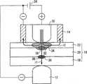
图2是纵向截面透视图,显示待焊的堆叠组件由第一电极端、第二电极端和支流电极夹住的方式;2 is a perspective view in longitudinal section showing the manner in which a stack assembly to be welded is sandwiched by a first electrode terminal, a second electrode terminal and a branch electrode;
图3是纵向截面透视图,显示电阻焊装置通过将电流从第一电极端到第二电极端穿过堆叠组件来启动电阻焊工艺的方式;Figure 3 is a perspective view in longitudinal section showing the manner in which the resistance welding apparatus initiates the resistance welding process by passing electrical current through the stacked assembly from the first electrode terminal to the second electrode terminal;
图4是纵向截面透视图,显示电阻焊装置在具有图3所示的电流启动通过后使电流持续通过的方式;Figure 4 is a perspective view in longitudinal section showing the manner in which the resistance welding device continues to pass current after the current has been initiated to pass as shown in Figure 3;
图5是纵向截面透视图,显示支流电极从堆叠组件升起而电阻焊装置继续使电流从第一电极端到第二电极端通过堆叠组件的方式;Figure 5 is a perspective view in longitudinal section showing the manner in which the tributary electrodes are lifted from the stack while the resistance welding device continues to pass current through the stack from the first electrode end to the second electrode end;
图6是纵向截面透视图,显示第一电极也从堆叠组件升起由此利用电流的通过而完成了电阻焊工艺的方式;Fig. 6 is a perspective view in longitudinal section showing the manner in which the first electrode is also lifted from the stacked assembly thereby completing the resistance welding process by passing an electric current;
图7是改进的电阻焊装置的纵向截面透视图,显示电流从第二电极端和支流电极流到第一电极端的方式;Fig. 7 is a longitudinal sectional perspective view of an improved resistance welding device, showing the manner in which current flows from the second electrode terminal and the branch electrode to the first electrode terminal;
图8是纵向截面透视图,显示电流从第一电极端通过堆叠组件中最上面的工件和直接在最上面的工件下面的工件流到支流电极的方式;8 is a perspective view in longitudinal section showing the manner in which current flows from the first electrode terminal through the uppermost workpiece in the stack assembly and the workpieces directly below the uppermost workpiece to the tributary electrode;
具体实施方式Detailed ways
下面会参考附图详细描述电阻焊方法,还与电阻焊装置相关,该装置执行根据本发明实施例的电阻焊方法。The resistance welding method will be described in detail below with reference to the accompanying drawings, also in relation to a resistance welding device that performs the resistance welding method according to an embodiment of the present invention.
图1是显示根据本发明实施例的电阻焊装置的局部横向截面透视图。如图1所示,电阻焊装置包括焊枪,未示出,其具有用作第一焊接电极的第一电极端10,用作第二焊接电极的第二电极端12,以及支流电极14。焊枪安装在诸如六轴机器人之类的多关节型机器人的手臂的末端。这样的将焊枪安装在手臂上的多关节型机器人是已知的现有技术,在此不详细描述。FIG. 1 is a partially transverse cross-sectional perspective view showing a resistance welding apparatus according to an embodiment of the present invention. As shown in FIG. 1 , the resistance welding apparatus includes a welding torch, not shown, having a
电阻焊装置用于焊接堆叠组件16。堆叠组件16包括三个金属板18、20、22,按这些附图标记所示的顺序从下相继堆叠工件。金属板18和20各具有厚度D1(例如,约1mm至2mm),而金属板22的厚度D2(例如,约0.5mm至0.7mm)小于厚度D1。换言之,金属板18和20的厚度相同,而金属板22比金属板18和20薄。以下还将金属板22称为“最薄工件”。A resistance welding device is used to weld the stacked
金属板18、20均包括,例如高强度钢,如JAC590、JAC780或JAC980(根据日本钢铁联盟标准(Japan Iron and Steel Federation Standard)限定的高性能高强度钢板)。最薄工件22包括,例如软钢,如JAC270(根据日本钢铁联盟标准限定的用于压力成型的高性能钢板)。金属板18、20可以包括相同金属或不同金属。Both
或者,所有的金属板18、20、22可以包括软钢。另外,金属板18可以包括高强度钢,而金属板20、22可以包括软钢。Alternatively, all
用于金属板18、20、22的材料不限于上述钢材,可以是任何能够电阻焊的材料。The material used for the
第一电极端10和第二电极端12均具有纵长棒形状,将堆叠组件16夹在中间,使电流通过堆叠组件16。本发明中,电流从第一电极端10流过堆叠组件16到第二电极端12。Both the
如果焊枪具有所谓的X型,那么第二电极端12安装在一对可打开和关闭的夹头中的一个上,而第一电极端10连接到滚珠丝杠上。当夹头移动而彼此靠近或远离时,第一电极端10和第二电极端12移动而彼此靠近或远离。If the welding torch has a so-called X-type, the
或者,如果焊枪具有所谓的C型,那么第一电极端10安装在固定臂的末端上,而第二电极端12安装在另一个夹头上。当滚珠丝杠绕自己的轴旋转时,第一电极端10移动而靠近或远离第二电极端12。Alternatively, if the welding torch has a so-called C-type, the
支流电极14为环状形状,设置成与第一电极端10呈围绕的关系。支撑第一电极端10的焊枪包括移位机构,如滚珠丝杠、泵缸等,以使支流电极14移位而靠近或远离堆叠组件16。移位机构能够使支流电极14独立于第一电极端10移动而靠近或远离堆叠组件16。The
在本实施例中,第一电极端10与直流电源24的正极端子电连接,而第二电极端12和支流电极14与直流电源24的负极端子电连接。虽然第一电极端10和支流电极24均接触堆叠组件16的最薄工件22,但第一电极端10与支流电极具有相反的极性。即,第一电极端10和支流电极14分别电连接到直流电源24的相反极性。In this embodiment, the
在上述结构中,当第一电极端10和支流电极14之间的距离Z过分大时,第一电极端10和支流电极14之间的电阻大。因此,对于下面要描述的分支电流(参见图3)来说,在第一电极端10和支流电极14之间流动是困难的。因而,距离Z确定为使第一电极端10和支流电极14之间的电阻能够使分支电流i2以合适的电流值流动。In the above structure, when the distance Z between the
根据本发明的电阻焊装置的基本结构如上所述。该电阻焊装置的操作和优势会在下面联系根据本发明的电阻焊方法进行说明。The basic structure of the resistance welding apparatus according to the present invention is as described above. The operation and advantages of the resistance welding device will be described below in connection with the resistance welding method according to the present invention.
为了电阻焊堆叠组件16,或者说为了使金属板18和20相互连接和使金属板20和22相互连接,机器人移动焊枪以使堆叠组件16定位在第一电极端10和第二电极端12之间。然后,夹头朝向彼此移动,或滚珠丝杠绕自己的轴旋转,以使第一电极端10和第二电极端12相对地朝向彼此移动,由此将堆叠组件16夹在第一电极端10和第二电极端12之间。To resistance weld the
同时,或随后,移位机构使支流电极14抵靠堆叠组件16的最薄工件22,如图2所示。Simultaneously, or subsequently, the displacement mechanism brings the
这时,支流电极14可保持为与最薄工件22接触,或在给定压力下压靠在对最薄工件22上。At this time, the
然后,直流电源24打开以给堆叠组件16提供电流。由于第一电极端10和第二电极端12分别电连接到直流电源24的正极和负极端子,电流i1从第一电极端10流过堆叠组件16到第二电极端12,如图3所示。金属板18和20之间的界面以及金属板20和22之间的界面现在由电流i1产生的焦耳热加热,由此分别产生受热区30、32。受热区30延伸到金属板18、20中,而受热区32延伸到金属板20、22中。Then, the
保持为抵靠最薄工件22的支流电极14电连接到直流电源24的负极端子。因此,在电流i1从第一电极端10流动的同时,分支电流i2也从第一电极端10流向支流电极14。因为支流电极14是环状形状的,所以分支电流i2从第一电极端10径向向外流向支流电极14。The
在本实施例中,分支电流i2只流过最薄工件22,而不流过金属板18、20。结果,流过最薄工件22的电流值大于只使用第一电极端10和第二电极端12夹住堆叠组件16的普通电阻焊工艺的电流值。In this embodiment, the branch current i2 only flows through the
因此,除了受热区32外,最薄工件22获得了在其中的另外的受热区34。另外,由于分支电流i2以径向型流动,受热区34以对应的径向型加热金属板20、22之间的界面。随着时间推移,受热区34扩展并在尺寸上变大,从而与受热区32结合,如图4所示。Thus, in addition to the
由于从结合的受热区32、34传来的热量,金属板20、22之间的界面充分地升温并开始融化。结果,熔核36在金属板20和22之间形成。Due to the heat transferred from the joined
在此情况下,由于分支电流i2的比例变大,受热区34能够变大。然而,如果分支电流i2的比例变得过分大,那么电流i1变小,受热区30、32因此变小。这样,熔核36的尺寸变得饱和,而熔核38的尺寸变小。因而,分支电流i2的比例优选地确定为使电流i1大得足以使熔核38充分生长。In this case, since the proportion of the branch current i2 becomes larger, the
顺带说明,分支电流i2相对于电流i1的比例能够调整,例如,通过改变如上所述的第一电极端10和支流电极14之间的距离Z(参见图1和2)。Incidentally, the ratio of the branch current i2 to the current i1 can be adjusted, for example, by changing the distance Z between the
只要电流持续流过第一电极端10和第二电极端12之间的堆叠组件16,熔核36就会随着时间的推移而长大。因此,通过持续使电流流过第一电极端10和第二电极端12之间的堆叠组件16,熔核36能够充分地长大。借助于对试样进行的电阻焊试验,能够预先确定熔核36相对于时间长大的速度,在该速度期间电流流过第一电极端10和第二电极端12之间的堆叠组件16。As long as current continues to flow through the
流过金属板18、20的电流i1的值小于普通电阻焊中的值。因此,施加在金属板18、20上的热量不会变得过大,而金属板20、22之间的熔核36持续长大。因而,金属板18、20消除了造成飞溅的趋势。The value of the current i1 flowing through the
另外,熔核38由金属板18、20之间的电流i1形成。当分支电流i2持续流动时,电流i1的总电能与分支电流i2的流动停止情况下的总电能相比要小。因此,受热区30进而熔核38倾向于变得稍小。In addition, the
因而,为进一步促进熔核38的生长,优选地,支流电极14从最薄工件22升起离开,而电流从第一电极端10到第二电极端12继续供应,如图5所示。这时,由于支流电极14不再与最薄工件22接触,因而从第一电极端10流到第二电极端12的电流在量值上变得更大,这样,电流i1的直到电流的施加结束时的总电能增加。Therefore, in order to further promote the growth of the
当分支电流i2消失,只有流向为从第一电极端10到第二电极端12的电流i1存留并流过最薄工件12。因此,在金属板20、22内的受热区34(参见图4)消失,如图5所示。When the branch current i2 disappears, only the current i1 flowing from the
这时,金属板18、20具有与通常的电阻焊工艺相同的表现方式。具体地说,由于加大的电流i1从第一电极端10流到第二电极端12,在金属板18、20产生焦耳热的增加量,由此造成受热区30在尺寸和温度上扩张和增加。金属板18、20之间的界面被温度升高的受热区30加热。金属板18、20之间的界面以及该界面的邻近区域的温度充分上升从而进一步融化,由此促进了熔核38的生长。In this case, the
为了熔核38充分长大,电流i1从第一电极端10到第二电极端12持续流过堆叠组件16,直到熔核38与金属板20、22之间的熔核36结合。借助于对试样进行的电阻焊试验,能够预先确定熔核38相对于时间长大的速度,在该速度期间电流流过第一电极端10和第二电极端12之间的堆叠组件16。In order for the
金属板18、20之间的界面提前被受热区30加热,该受热区30是由出于形成金属板20、22之间的熔核36的目的通过的电流i1形成的。因而,金属板18、20在熔核38开始长大以前变得相互充分混合。因而金属板18、20不易造成飞溅。The interface between the
根据本实施例,如上所述,金属板18、20、22避免了在金属板20、22之间的熔核36以及金属板18、20之间的熔核38长大时造成飞溅。According to the present embodiment, as described above, the
当熔核38经过预定的时段已充分长大时,直流电源24关闭,从而电流停止通过第一电极端10和第二电极端12之间的堆叠组件16。然后,第一电极端10从最薄工件22升起离开,如图6所示。或者,不是关闭直流电源24,第一电极端10可以简单地从最薄工件22升起脱离。这样,第一电极端10与第二电极端12变成电隔离,由此停止电流流过第一电极端10和第二电极端12之间的堆叠组件16。When the
电阻焊工艺的从开始到结束的上述操作是在未示出的控制电路的控制下进行的。The above-mentioned operations from the beginning to the end of the resistance welding process are performed under the control of an unshown control circuit.
当电流停止时,金属板18、20、22的加热也停止。熔核38随着时间的推移变冷和凝固,由此使金属板18、20相互牢固连接。类似地,熔核36随着时间的推移变冷和凝固,由此使金属板20、22相互牢固连接。When the current is stopped, the heating of the
由此,金属板18、20、22焊接到一起,产生期望的焊接产品。Thereby, the
由于具有充分长大的熔核38,该焊接产品表现出金属板18、20之间优秀的连接强度。该焊接产品还表现出金属板20、22之间的优秀的连接强度,这是因为具有流过最薄工件22的分支电流i2,产生了在金属板20、22之间充分长大的熔核36。Due to the sufficiently grown
从以上说明可知,通过将支流电极14加入已有的电阻焊装置,再加上用于移位支流电极14的移位机构,就基本上构成了本实施例的电阻焊装置。在增加支流电极14和移位机构的情况下,不会导致电阻焊装置在结构上过度复杂。As can be seen from the above description, by adding the
在以上示出的实施例中,在第一电极端10与最薄工件22间隔开以前,支流电极14与最薄工件12间隔开。然而,取决于电流i1和分支电流i2的值,支流电极14和第一电极端10可同时与最薄工件22间隔开。In the embodiment shown above, the
根据本发明实施例的电阻焊装置电阻焊的堆叠组件16可以包括4个或更多个金属板。The resistance welded
另外,图7显示改进的电阻焊装置,其中电流从保持为抵靠金属板18的第二电极端12流到保持为抵靠最薄工件22的第一电极端10。保持为抵靠最薄工件22的支流电极14具有与第一电极端10的极性相反的极性。具体地说,第二电极端12和支流电极14电连接到直流电源24的负极端子,而第一电极端10电连接到直流电源24的负极端子。作为图7所示电连接的结果,电流i1从第二电极端12流到第一电极端10,分支电流i2从支流电极14流到第一电极端10。Additionally, FIG. 7 shows a modified resistance welding apparatus in which current flows from the
作为将支流电极14与最薄工件22间隔开的替代,可以将开关电连接在最薄工件22和直流电源24之间。可以将该开关断开以停止图1-6所示的实施例中的从第一电极端10流到支流电极14的电流,或者停止图7所示的变形例中的从支流电极14流到第一电极端10的电流。可以闭合该开关以形成受热区34。Instead of spacing the
如果上述开关电连接在最薄工件22和直流电源24之间,那么用于独立于第一电极端10移位支流电极14靠近或远离堆叠组件16的移位机构可以省略。因而,电阻焊装置能够在结构上制造得更简单,控制电阻焊装置的工艺也得到简化。If the aforementioned switch is electrically connected between the
无论是在上述实施例还是在其变形例中,支流电极14不一定要限定为环状形状。作为替换,支流电极14可以为纵长棒形状,类似于第一电极端10和第二电极端12。电阻焊装置可以包括多个均为纵长棒形状的支流电极14,这些支流电极同时成为与最薄工件22接触或者与最薄工件22脱离接触。The
另外,如图8所示,在以上实施例中,分支电流i2可以不仅流过与第一电极端10接触的最薄工件22而且流过直接位于最薄工件22下面的金属板20。In addition, as shown in FIG. 8 , in the above embodiment, the branch current i2 may flow not only through the
在此情况下,电阻热在最薄工件22和金属板20之间产生,然后形成熔核36。另一方面,没有从第一电极端10到支流电极14在金属板18、22之间流动的电流,或者,即使有这样的电流,也只有极小的电流流动。这样,在最薄工件22和金属板20之间形成的熔核36容易长大。In this case, resistive heat is generated between the
尽管上面已经示出和描述了本发明的一些优选实施例,但是应理解,在不脱离权利要求书所提出的本发明范围的情况下,能够对这些实施例作出变化和改进。Although preferred embodiments of the present invention have been shown and described above, it should be understood that changes and modifications can be made to these embodiments without departing from the scope of the invention as set forth in the claims.
Claims (13)
Applications Claiming Priority (4)
| Application Number | Priority Date | Filing Date | Title |
|---|---|---|---|
| JP2009087946 | 2009-03-31 | ||
| JP087946/09 | 2009-03-31 | ||
| JP2010061024AJP5427074B2 (en) | 2009-03-31 | 2010-03-17 | Resistance welding method and apparatus |
| JP061024/10 | 2010-03-17 |
Publications (2)
| Publication Number | Publication Date |
|---|---|
| CN101850468A CN101850468A (en) | 2010-10-06 |
| CN101850468Btrue CN101850468B (en) | 2013-05-29 |
Family
ID=42782833
Family Applications (1)
| Application Number | Title | Priority Date | Filing Date |
|---|---|---|---|
| CN201010159444.1AActiveCN101850468B (en) | 2009-03-31 | 2010-03-31 | Resistance welding method and resistance welding apparatus |
Country Status (3)
| Country | Link |
|---|---|
| US (1) | US8253056B2 (en) |
| JP (1) | JP5427074B2 (en) |
| CN (1) | CN101850468B (en) |
Families Citing this family (22)
| Publication number | Priority date | Publication date | Assignee | Title |
|---|---|---|---|---|
| JP5411792B2 (en)* | 2009-06-05 | 2014-02-12 | 本田技研工業株式会社 | Resistance welding method and apparatus |
| CN102248270A (en)* | 2010-05-21 | 2011-11-23 | 通用汽车环球科技运作公司 | Welding system |
| EP2614913B1 (en)* | 2010-09-06 | 2020-06-10 | Honda Motor Co., Ltd. | Welding method and welding device |
| JP5758667B2 (en)* | 2011-03-24 | 2015-08-05 | 富士重工業株式会社 | Spot welding equipment |
| JP5369150B2 (en)* | 2011-08-09 | 2013-12-18 | 富士重工業株式会社 | Spot welding equipment |
| JP5513460B2 (en)* | 2011-09-27 | 2014-06-04 | 富士重工業株式会社 | Spot welding equipment |
| CN104302434B (en)* | 2012-05-18 | 2017-05-17 | 本田技研工业株式会社 | Spot welding device and spot welding method |
| WO2014045431A1 (en)* | 2012-09-24 | 2014-03-27 | 新日鐵住金株式会社 | Spot welding method for high-strength steel sheet excellent in joint strength |
| JP5814906B2 (en)* | 2012-12-10 | 2015-11-17 | 本田技研工業株式会社 | Resistance welding method and resistance welding apparatus |
| DE102013014701A1 (en)* | 2013-09-05 | 2015-03-05 | GM Global Technology Operations LLC (n. d. Ges. d. Staates Delaware) | Welding assembly for welding a connection portion and method for welding the connection portion to the welding assembly |
| WO2015083835A1 (en)* | 2013-12-06 | 2015-06-11 | 新日鐵住金株式会社 | Electrode for spot welding, and welding device and welding method employing same |
| EP3112079A4 (en)* | 2014-02-24 | 2017-03-15 | Howon Co. Ltd. | Hybrid welder |
| CN106061665B (en)* | 2014-03-14 | 2019-07-05 | 日本制铁株式会社 | Welded structure and method of manufacturing welded structure |
| US20150314363A1 (en)* | 2014-04-30 | 2015-11-05 | GM Global Technology Operations LLC | Method of forming a vehicle body structure from a pre-welded blank assembly |
| CN107000109B (en)* | 2014-12-01 | 2021-09-10 | 杰富意钢铁株式会社 | Resistance spot welding method |
| KR20170004766A (en)* | 2015-07-03 | 2017-01-11 | 주식회사 성우하이텍 | Vibration spot welding device |
| JP6572281B2 (en)* | 2017-10-06 | 2019-09-04 | ファナック株式会社 | Spot welding system |
| CN111163894A (en)* | 2017-11-15 | 2020-05-15 | 日本制铁株式会社 | Spot welding method |
| KR101953998B1 (en)* | 2017-11-17 | 2019-03-04 | 부경대학교 산학협력단 | Electric resistance spot welding machine by multi current supply and multi pressure |
| JP7010720B2 (en)* | 2018-02-13 | 2022-01-26 | トヨタ自動車株式会社 | Resistance spot welding method |
| JP7208193B2 (en)* | 2020-07-08 | 2023-01-18 | フタバ産業株式会社 | Resistance spot welding method and resistance spot welding device |
| KR20230010561A (en)* | 2021-07-12 | 2023-01-19 | 현대자동차주식회사 | Spot welding method for multi-layers and spot welding apparatus using the same |
Citations (2)
| Publication number | Priority date | Publication date | Assignee | Title |
|---|---|---|---|---|
| US3643057A (en)* | 1967-02-11 | 1972-02-15 | Otto Alfred Becker | Resistance welding of sheet metal coated with layers |
| US5977505A (en)* | 1997-03-13 | 1999-11-02 | Honda Giken Kogyo Kabushiki Kaisha | Electric resistance welding method with unequal force application |
Family Cites Families (10)
| Publication number | Priority date | Publication date | Assignee | Title |
|---|---|---|---|---|
| JPS57151114A (en)* | 1981-03-12 | 1982-09-18 | Mitsubishi Electric Corp | Resistance welding machine |
| JPS59193773A (en) | 1983-04-18 | 1984-11-02 | Mitsubishi Electric Corp | Weld bond method |
| JPS61165282A (en)* | 1985-01-16 | 1986-07-25 | Mitsubishi Heavy Ind Ltd | Electrode for spot welding |
| JPS63183781A (en) | 1986-12-20 | 1988-07-29 | Toyota Motor Corp | Resistance welding equipment for metal materials with plating coating |
| JP2510874Y2 (en)* | 1991-09-30 | 1996-09-18 | 武巳 田中 | Spot welder |
| JP3922263B2 (en)* | 2004-03-17 | 2007-05-30 | Jfeスチール株式会社 | Method of manufacturing resistance spot welded joint |
| JP5105788B2 (en)* | 2006-07-20 | 2012-12-26 | Necエナジーデバイス株式会社 | Micro spot resistance welding apparatus and welding method thereof |
| JP5128159B2 (en) | 2007-03-30 | 2013-01-23 | 本田技研工業株式会社 | Resistance welding method |
| JP4494496B2 (en)* | 2008-06-06 | 2010-06-30 | 本田技研工業株式会社 | Resistance welding method and welded structure |
| JP5411792B2 (en)* | 2009-06-05 | 2014-02-12 | 本田技研工業株式会社 | Resistance welding method and apparatus |
- 2010
- 2010-03-17JPJP2010061024Apatent/JP5427074B2/enactiveActive
- 2010-03-30USUS12/749,771patent/US8253056B2/enactiveActive
- 2010-03-31CNCN201010159444.1Apatent/CN101850468B/enactiveActive
Patent Citations (2)
| Publication number | Priority date | Publication date | Assignee | Title |
|---|---|---|---|---|
| US3643057A (en)* | 1967-02-11 | 1972-02-15 | Otto Alfred Becker | Resistance welding of sheet metal coated with layers |
| US5977505A (en)* | 1997-03-13 | 1999-11-02 | Honda Giken Kogyo Kabushiki Kaisha | Electric resistance welding method with unequal force application |
Also Published As
| Publication number | Publication date |
|---|---|
| CN101850468A (en) | 2010-10-06 |
| JP2010253551A (en) | 2010-11-11 |
| US20100243616A1 (en) | 2010-09-30 |
| US8253056B2 (en) | 2012-08-28 |
| JP5427074B2 (en) | 2014-02-26 |
Similar Documents
| Publication | Publication Date | Title |
|---|---|---|
| CN101850468B (en) | Resistance welding method and resistance welding apparatus | |
| JP5415896B2 (en) | Indirect spot welding method | |
| US9676052B2 (en) | Resistance welding method | |
| CN103180082B (en) | Welding method and welder | |
| CN107000109A (en) | Resistance spot welding method | |
| US9505078B2 (en) | Spot welding method and spot welding apparatus | |
| JP6032285B2 (en) | Indirect spot welding method | |
| CN105517747B (en) | Single side spot welding device | |
| JP7010720B2 (en) | Resistance spot welding method | |
| WO2015037652A1 (en) | Resistance spot welding method and welded structure | |
| JP5005220B2 (en) | Method for welding connection plate in battery pack | |
| JP6516247B2 (en) | One side spot welding method | |
| JP5625423B2 (en) | Indirect spot welding method | |
| JP2022085358A (en) | Resistance spot welding method | |
| JP5519451B2 (en) | Resistance welding method and system | |
| JP5519450B2 (en) | Resistance welding system and resistance welding method | |
| KR101204884B1 (en) | method for welding aluminum alloy use moving high-frequency coil | |
| US1342957A (en) | Method of resistance welding | |
| JP5756076B2 (en) | Indirect spot welding method | |
| JP2013169547A (en) | Seam welding method and apparatus thereof | |
| CN118720375A (en) | Method and welding device for manufacturing a welded structure | |
| JPS5921271B2 (en) | Tsukiawaseyyousetsuki | |
| JP2023132920A (en) | welding electrode | |
| CN116847940A (en) | Methods for joining dissimilar metal parts | |
| JPH01130892A (en) | Electrification heating type welding machine |
Legal Events
| Date | Code | Title | Description |
|---|---|---|---|
| C06 | Publication | ||
| PB01 | Publication | ||
| C10 | Entry into substantive examination | ||
| SE01 | Entry into force of request for substantive examination | ||
| C14 | Grant of patent or utility model | ||
| GR01 | Patent grant |