CN101846124A - Combined screw - Google Patents
Combined screwDownload PDFInfo
- Publication number
- CN101846124A CN101846124ACN200910301095ACN200910301095ACN101846124ACN 101846124 ACN101846124 ACN 101846124ACN 200910301095 ACN200910301095 ACN 200910301095ACN 200910301095 ACN200910301095 ACN 200910301095ACN 101846124 ACN101846124 ACN 101846124A
- Authority
- CN
- China
- Prior art keywords
- screw
- nut
- receiving hole
- combined
- combination
- Prior art date
- Legal status (The legal status is an assumption and is not a legal conclusion. Google has not performed a legal analysis and makes no representation as to the accuracy of the status listed.)
- Granted
Links
Images

Classifications
- F—MECHANICAL ENGINEERING; LIGHTING; HEATING; WEAPONS; BLASTING
- F16—ENGINEERING ELEMENTS AND UNITS; GENERAL MEASURES FOR PRODUCING AND MAINTAINING EFFECTIVE FUNCTIONING OF MACHINES OR INSTALLATIONS; THERMAL INSULATION IN GENERAL
- F16B—DEVICES FOR FASTENING OR SECURING CONSTRUCTIONAL ELEMENTS OR MACHINE PARTS TOGETHER, e.g. NAILS, BOLTS, CIRCLIPS, CLAMPS, CLIPS OR WEDGES; JOINTS OR JOINTING
- F16B35/00—Screw-bolts; Stay-bolts; Screw-threaded studs; Screws; Set screws
- F16B35/04—Screw-bolts; Stay-bolts; Screw-threaded studs; Screws; Set screws with specially-shaped head or shaft in order to fix the bolt on or in an object
- F16B35/041—Specially-shaped shafts
- F—MECHANICAL ENGINEERING; LIGHTING; HEATING; WEAPONS; BLASTING
- F16—ENGINEERING ELEMENTS AND UNITS; GENERAL MEASURES FOR PRODUCING AND MAINTAINING EFFECTIVE FUNCTIONING OF MACHINES OR INSTALLATIONS; THERMAL INSULATION IN GENERAL
- F16B—DEVICES FOR FASTENING OR SECURING CONSTRUCTIONAL ELEMENTS OR MACHINE PARTS TOGETHER, e.g. NAILS, BOLTS, CIRCLIPS, CLAMPS, CLIPS OR WEDGES; JOINTS OR JOINTING
- F16B23/00—Specially shaped nuts or heads of bolts or screws for rotations by a tool
- F16B23/0007—Specially shaped nuts or heads of bolts or screws for rotations by a tool characterised by the shape of the recess or the protrusion engaging the tool
- F16B23/0015—Specially shaped nuts or heads of bolts or screws for rotations by a tool characterised by the shape of the recess or the protrusion engaging the tool substantially rectangular, e.g. one-slot head
- F—MECHANICAL ENGINEERING; LIGHTING; HEATING; WEAPONS; BLASTING
- F16—ENGINEERING ELEMENTS AND UNITS; GENERAL MEASURES FOR PRODUCING AND MAINTAINING EFFECTIVE FUNCTIONING OF MACHINES OR INSTALLATIONS; THERMAL INSULATION IN GENERAL
- F16B—DEVICES FOR FASTENING OR SECURING CONSTRUCTIONAL ELEMENTS OR MACHINE PARTS TOGETHER, e.g. NAILS, BOLTS, CIRCLIPS, CLAMPS, CLIPS OR WEDGES; JOINTS OR JOINTING
- F16B23/00—Specially shaped nuts or heads of bolts or screws for rotations by a tool
- F16B23/0007—Specially shaped nuts or heads of bolts or screws for rotations by a tool characterised by the shape of the recess or the protrusion engaging the tool
- F16B23/0023—Specially shaped nuts or heads of bolts or screws for rotations by a tool characterised by the shape of the recess or the protrusion engaging the tool substantially cross-shaped
- F—MECHANICAL ENGINEERING; LIGHTING; HEATING; WEAPONS; BLASTING
- F16—ENGINEERING ELEMENTS AND UNITS; GENERAL MEASURES FOR PRODUCING AND MAINTAINING EFFECTIVE FUNCTIONING OF MACHINES OR INSTALLATIONS; THERMAL INSULATION IN GENERAL
- F16B—DEVICES FOR FASTENING OR SECURING CONSTRUCTIONAL ELEMENTS OR MACHINE PARTS TOGETHER, e.g. NAILS, BOLTS, CIRCLIPS, CLAMPS, CLIPS OR WEDGES; JOINTS OR JOINTING
- F16B35/00—Screw-bolts; Stay-bolts; Screw-threaded studs; Screws; Set screws
- F16B35/04—Screw-bolts; Stay-bolts; Screw-threaded studs; Screws; Set screws with specially-shaped head or shaft in order to fix the bolt on or in an object
- F16B35/06—Specially-shaped heads
Landscapes
- Engineering & Computer Science (AREA)
- General Engineering & Computer Science (AREA)
- Mechanical Engineering (AREA)
- Transmission Devices (AREA)
- Connection Of Plates (AREA)
Abstract
Description
Translated fromChinese技术领域technical field
本发明涉及一种螺丝,特别涉及一种组合螺丝。The invention relates to a screw, in particular to a combined screw.
背景技术Background technique
螺丝是许多机构设备中最基本的组件之一,许多机构设备在组装零件时,都需要使用至少两种专用型号的螺丝,以将分离的零件固定在一起。例如,在电脑以及服务器的机箱内,通常具有很多规格大小不同的螺丝,用以固定散热器,主板,硬盘,光驱以及扩展卡等不同组件,而小规格的螺丝因为体积小等原因很容易丢失,当使用者或者维修人员在拆装电脑以及服务器时,经常因为小规格螺丝的丢失而无专用的备用螺丝,造成维护的困扰。Screws are one of the most basic components in many institutional devices. Many institutional devices require at least two special types of screws to fix the separated parts together when assembling parts. For example, in the chassis of computers and servers, there are usually many screws of different sizes to fix different components such as radiators, motherboards, hard drives, optical drives, and expansion cards. Smaller size screws are easy to lose due to their small size. , when users or maintenance personnel are disassembling computers and servers, they often have no special spare screws due to the loss of small-sized screws, causing maintenance troubles.
发明内容Contents of the invention
鉴于以上内容,有必要提供一种组合螺丝,在小规格螺丝丢失时可及时找到相同规格的备用螺丝。In view of the above, it is necessary to provide a combination screw, which can find a spare screw of the same specification in time when the small specification screw is lost.
一种组合螺丝,包括一第一螺丝及一较所述第一螺丝规格较小的第二螺丝,所述第一螺丝上开设有一收容孔,所述第二螺丝收容于所述收容孔内并与所述第一螺丝锁合在一起。A combined screw, comprising a first screw and a second screw with a smaller specification than the first screw, a receiving hole is opened on the first screw, the second screw is accommodated in the receiving hole and locked together with the first screw.
一种组合螺丝,包括一第一螺丝及一较所述第一螺丝规格较小的第二螺丝,所述第一螺丝上开设有一收容孔,当所述第二螺丝收容锁合于所述收容孔内可作为备用螺丝,所述第二螺丝从所述收容孔取出可单独使用。A combined screw, comprising a first screw and a second screw with a smaller specification than the first screw, a receiving hole is opened on the first screw, when the second screw is stored and locked in the receiving The hole can be used as a spare screw, and the second screw can be taken out from the receiving hole and used alone.
所述组合螺丝中的第二螺丝既可锁合在所述第一螺丝中以备急需,也可从所述第一螺丝中取出单独使用,避免了当丢失小规格的螺丝时而找不到相同规格的备用螺丝的麻烦。The second screw in the combination screw can be locked in the first screw for urgent need, and can also be taken out from the first screw for separate use, so as to avoid finding the same screw when a small-sized screw is lost. The hassle of spare screws to spec.
附图说明Description of drawings
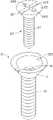
图1是本发明组合螺丝较佳实施方式的立体分解图。Fig. 1 is a three-dimensional exploded view of a preferred embodiment of the combination screw of the present invention.
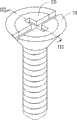
图2是本发明组合螺丝较佳实施方式的立体组合图。Fig. 2 is a three-dimensional assembled view of a preferred embodiment of the assembled screw of the present invention.
图3沿图2中III-III线的剖面图。Fig. 3 is a sectional view along line III-III in Fig. 2 .
具体实施方式Detailed ways
下面结合附图及较佳实施方式对本发明作进一步详细描述:Below in conjunction with accompanying drawing and preferred embodiment the present invention is described in further detail:
请参照图1、图2及图3,本发明组合螺丝的较佳实施方式包括一第一螺丝10及一第二螺丝20。所述第一螺丝10为一大规格的螺丝,所述第二螺丝20为一小规格的螺丝,所述第一螺丝10包括一螺帽12及一外表面切削有螺纹的螺杆14,所述螺杆14与所述螺帽12连为一体。所述第二螺丝20包括一螺帽22及一外表面切削有螺纹的螺杆24,所述螺杆24与所述螺帽22连为一体,本实施方式中,所述螺帽12及14大致为圆锥状,所述第二螺丝20较所述第一螺丝10的尺寸小。Please refer to FIG. 1 , FIG. 2 and FIG. 3 , a preferred embodiment of the combination screw of the present invention includes a
所述第一螺丝10内设有一收容孔16,所述收容孔16自所述螺帽12延伸至所述螺杆14内,所述收容孔16在所述螺帽12内的部分大致呈圆锥状,可收容第二螺丝20的螺帽22,所述收容孔16在螺杆14内的部分设有螺纹,可旋转锁合第二螺丝20的螺杆24。所述螺帽12的上表面上沿所述收容孔16的外围对称开设有两沟槽122,本实施方式中,当第二螺丝20旋转锁合于第一螺丝10时,所述收容孔16与所述第一螺丝10的中心轴互相重合,一螺丝刀伸入所述两沟槽122可旋转锁合第一螺丝10。A receiving
所述第二螺帽22的中心处开设有两两对应并相互连通成十字形的缺槽222及沟槽224,当所述第二螺丝20作为一备用螺丝时,其通过所述螺杆24上的螺纹锁合于所述第一螺丝10的收容孔16内,当所述第一、第二螺丝10及20锁合在一起时,所述螺杆24收容于所述收容孔16在所述螺杆14内的部分,所述螺帽22收容于所述收容孔16在所述螺帽12内的部分,每一沟槽122与一对应的沟槽224相连通,因此,使用一尺寸较大的螺丝刀伸入沟槽122及224可旋转锁合所述第一螺丝10,无需取出所述第二螺丝20。The center of the
当需要单独使用所述第二螺丝20时,可使用一尺寸较小的螺丝刀伸入沟槽224,从所述第一螺丝10中旋转地取出所述第二螺丝20。When the
因此,当机构设备中的第二螺丝20,即较小规格的螺丝丢失时,可从所述第一螺丝10中取出所述第二螺丝20来使用,为所述机构设备的后续维护带来方便。Therefore, when the
Claims (7)
Translated fromChinesePriority Applications (2)
| Application Number | Priority Date | Filing Date | Title |
|---|---|---|---|
| CN200910301095XACN101846124B (en) | 2009-03-24 | 2009-03-24 | Combined screw |
| US12/436,760US7985040B2 (en) | 2009-03-24 | 2009-05-06 | Screw assembly |
Applications Claiming Priority (1)
| Application Number | Priority Date | Filing Date | Title |
|---|---|---|---|
| CN200910301095XACN101846124B (en) | 2009-03-24 | 2009-03-24 | Combined screw |
Publications (2)
| Publication Number | Publication Date |
|---|---|
| CN101846124Atrue CN101846124A (en) | 2010-09-29 |
| CN101846124B CN101846124B (en) | 2013-08-28 |
Family
ID=42770874
Family Applications (1)
| Application Number | Title | Priority Date | Filing Date |
|---|---|---|---|
| CN200910301095XAExpired - Fee RelatedCN101846124B (en) | 2009-03-24 | 2009-03-24 | Combined screw |
Country Status (2)
| Country | Link |
|---|---|
| US (1) | US7985040B2 (en) |
| CN (1) | CN101846124B (en) |
Cited By (1)
| Publication number | Priority date | Publication date | Assignee | Title |
|---|---|---|---|---|
| CN102763937A (en)* | 2012-07-31 | 2012-11-07 | 朱明龙 | Special sleeved wear-resistant antiskid bolt for sole |
Families Citing this family (29)
| Publication number | Priority date | Publication date | Assignee | Title |
|---|---|---|---|---|
| DE102011116047A1 (en)* | 2011-10-17 | 2013-04-18 | Sram Deutschland Gmbh | Derailleur guide apparatus |
| US9206832B1 (en)* | 2011-11-23 | 2015-12-08 | Apa Services, Inc. | Connection node and method of use |
| GB2498769A (en)* | 2012-01-27 | 2013-07-31 | Hardie James Technology Ltd | Fastener with cap |
| US20130215381A1 (en)* | 2012-02-21 | 2013-08-22 | Puthalath Koroth Raghuprasad | Nested screw fastener |
| US20140150241A1 (en)* | 2012-11-16 | 2014-06-05 | Patricia McNeal | Reinforcement screw insert |
| US20150023760A1 (en)* | 2013-07-19 | 2015-01-22 | Antonio Bove, III | Drywall anchor device |
| TWM475794U (en)* | 2013-12-02 | 2014-04-01 | Giga Byte Tech Co Ltd | Stud |
| GB2524520A (en)* | 2014-03-25 | 2015-09-30 | Lillemor Ltd | Fasteners |
| CN104006053A (en)* | 2014-06-05 | 2014-08-27 | 常州市南飞机械有限公司 | Multifunctional detachable bolt |
| US20160208840A1 (en)* | 2015-01-16 | 2016-07-21 | Matthew Neber | Fastener With Removable Head End |
| US10443644B2 (en)* | 2015-02-09 | 2019-10-15 | Syntiro Dynamics Llc | Anchor sealing hygienic bracket |
| US9759510B1 (en)* | 2016-03-09 | 2017-09-12 | James J. Kempf | Vibration dampening limb bolt |
| PL3658717T3 (en)* | 2017-07-25 | 2021-12-13 | Sanitea S.R.L. | Expansible sleeve for facilitating the installation of wall-hung objects, kit comprising said sleeve and related method |
| CN107269654A (en)* | 2017-07-31 | 2017-10-20 | 太仓市众翔精密五金有限公司 | A kind of special-shaped stud baking vanish part of highly efficient durable and its baking vanish |
| WO2019195724A1 (en)* | 2018-04-06 | 2019-10-10 | Nill Lance | Combined anchor, fastener and leveling assembly |
| US10501939B2 (en) | 2017-12-22 | 2019-12-10 | Lance Nill | Anchor platform assembly |
| US10914334B2 (en) | 2018-03-30 | 2021-02-09 | Food Grade Solutions, Llc | Wall mounting assembly |
| US11428255B2 (en) | 2018-03-30 | 2022-08-30 | Food Grade Solutions, Llc | Wall mounting assembly |
| US10746216B2 (en)* | 2018-03-30 | 2020-08-18 | Food Grade Solutions, Llc | Wall mounting assembly |
| GB201817127D0 (en)* | 2018-10-21 | 2018-12-05 | Excalibur Screwbolts Ltd | Improvements in or relating to anchor bolts |
| KR20210129099A (en)* | 2019-02-14 | 2021-10-27 | 랜스 닐 | Anchor-balustrade assembly |
| CN110685988B (en)* | 2019-10-12 | 2021-08-03 | 嘉兴震辰五金科技股份有限公司 | Split type countersunk cross self-drilling screw |
| CN110685989B (en)* | 2019-10-12 | 2021-08-03 | 嘉兴震辰五金科技股份有限公司 | Round-head washer cross drill tail screw |
| US11773892B2 (en)* | 2020-06-01 | 2023-10-03 | Robert Alexander Halm | Threaded fastener with improved resistance to backing out of a blind hole |
| US11624397B2 (en)* | 2020-06-17 | 2023-04-11 | Daniel Stempfley | Fastening nut device |
| USD1015859S1 (en)* | 2021-12-21 | 2024-02-27 | Hoffman Enclosures, Inc. | Fastener |
| WO2024025106A1 (en)* | 2022-07-29 | 2024-02-01 | 삼성전자주식회사 | Electronic device comprising stacked screw structure |
| USD1036969S1 (en) | 2022-08-12 | 2024-07-30 | Food Grade Solutions, Llc | Wall mount assembly |
| US11767804B1 (en)* | 2023-01-30 | 2023-09-26 | GM Global Technology Operations LLC | Cast engine block having a hybrid threaded insert |
Citations (4)
| Publication number | Priority date | Publication date | Assignee | Title |
|---|---|---|---|---|
| US1194792A (en)* | 1916-08-15 | Telescopic lock screw-bolt oe | ||
| US5964767A (en)* | 1997-09-12 | 1999-10-12 | Tapia; Eduardo Armando | Hollow sealable device for temporary or permanent surgical placement through a bone to provide a passageway into a cavity or internal anatomic site in a mammal |
| CN2384021Y (en)* | 1999-08-06 | 2000-06-21 | 康智 | Adjustable bolt capable of preventing being detached by theft |
| CN2394045Y (en)* | 1999-07-15 | 2000-08-30 | 王德雁 | Screw |
Family Cites Families (8)
| Publication number | Priority date | Publication date | Assignee | Title |
|---|---|---|---|---|
| US2258326A (en)* | 1940-02-23 | 1941-10-07 | Grant J Holt | Screwhead |
| US4097061A (en)* | 1976-04-19 | 1978-06-27 | Dietlein Robert W | Ski insert for anchoring a ski binding screw in a ski |
| US4486134A (en)* | 1982-05-17 | 1984-12-04 | White Timothy T | Adjustable connector assembly |
| US4822223A (en)* | 1987-09-23 | 1989-04-18 | Williams William L | Wood insert |
| US5312005A (en)* | 1991-07-25 | 1994-05-17 | Odell Gordon T | Rack release mounting assembly |
| TW450330U (en)* | 2000-04-21 | 2001-08-11 | Meteck Entpr Co Ltd | Improved common type screw structure |
| US6361258B1 (en)* | 2000-07-06 | 2002-03-26 | Gary V. Heesch | Permanently placeable fasteners, inserter head for fastener placement and related methods |
| GB2387633B (en)* | 2002-04-18 | 2004-02-25 | Joker Ind Co Ltd | Nail anchor |
- 2009
- 2009-03-24CNCN200910301095XApatent/CN101846124B/ennot_activeExpired - Fee Related
- 2009-05-06USUS12/436,760patent/US7985040B2/ennot_activeExpired - Fee Related
Patent Citations (4)
| Publication number | Priority date | Publication date | Assignee | Title |
|---|---|---|---|---|
| US1194792A (en)* | 1916-08-15 | Telescopic lock screw-bolt oe | ||
| US5964767A (en)* | 1997-09-12 | 1999-10-12 | Tapia; Eduardo Armando | Hollow sealable device for temporary or permanent surgical placement through a bone to provide a passageway into a cavity or internal anatomic site in a mammal |
| CN2394045Y (en)* | 1999-07-15 | 2000-08-30 | 王德雁 | Screw |
| CN2384021Y (en)* | 1999-08-06 | 2000-06-21 | 康智 | Adjustable bolt capable of preventing being detached by theft |
Cited By (2)
| Publication number | Priority date | Publication date | Assignee | Title |
|---|---|---|---|---|
| CN102763937A (en)* | 2012-07-31 | 2012-11-07 | 朱明龙 | Special sleeved wear-resistant antiskid bolt for sole |
| CN102763937B (en)* | 2012-07-31 | 2015-01-14 | 朱明龙 | Special sleeved wear-resistant antiskid bolt for sole |
Also Published As
| Publication number | Publication date |
|---|---|
| US7985040B2 (en) | 2011-07-26 |
| CN101846124B (en) | 2013-08-28 |
| US20100247270A1 (en) | 2010-09-30 |
Similar Documents
| Publication | Publication Date | Title |
|---|---|---|
| CN101846124A (en) | Combined screw | |
| CN201092980Y (en) | Fan module group assembly | |
| US10957361B2 (en) | Tool-less storage device adaptor tray with slider mechanism | |
| US10608355B2 (en) | Tool-less top service of m.2 latch on board | |
| CN104765425A (en) | Server device | |
| TWI445888B (en) | Screw assembly | |
| CN102221855B (en) | Hard disk bracket | |
| CN101839418A (en) | Rotating reading lamp and locating structure thereof | |
| US20140211401A1 (en) | Fixing mechanism for fixing a storage module of an electronic device and electronic device therewith | |
| DE102016000700B4 (en) | RETRACTABLE GUIDES FOR DATA STORAGE DEVICE CARRIER | |
| CN106413329B (en) | Tool-free part bearing mechanism and electronic device | |
| CN102809994A (en) | Fixtures | |
| US20110268532A1 (en) | Fastening apparatus | |
| US10088877B2 (en) | Board card module | |
| CN102830765A (en) | Fixture | |
| US8642892B2 (en) | Circuit board with handles | |
| AU2018102124A4 (en) | Connection lock for use with LED display screen case body | |
| CN219981196U (en) | Locking mechanism | |
| US20110273068A1 (en) | Computer case | |
| CN102789284A (en) | Removable device | |
| CN203823363U (en) | Display device and fixing assembly thereof | |
| CN2916731Y (en) | Automatic closing spindle | |
| US12228980B2 (en) | Mounting system for an electronic device | |
| US8797733B2 (en) | Fastening module | |
| US9465411B2 (en) | Electronic device |
Legal Events
| Date | Code | Title | Description |
|---|---|---|---|
| C06 | Publication | ||
| PB01 | Publication | ||
| C10 | Entry into substantive examination | ||
| SE01 | Entry into force of request for substantive examination | ||
| C14 | Grant of patent or utility model | ||
| GR01 | Patent grant | ||
| C17 | Cessation of patent right | ||
| CF01 | Termination of patent right due to non-payment of annual fee | Granted publication date:20130828 Termination date:20140324 |