CN101846086B - A fluid testing experimental device for a centrifugal pump - Google Patents
A fluid testing experimental device for a centrifugal pumpDownload PDFInfo
- Publication number
- CN101846086B CN101846086BCN2010101904359ACN201010190435ACN101846086BCN 101846086 BCN101846086 BCN 101846086BCN 2010101904359 ACN2010101904359 ACN 2010101904359ACN 201010190435 ACN201010190435 ACN 201010190435ACN 101846086 BCN101846086 BCN 101846086B
- Authority
- CN
- China
- Prior art keywords
- pump casing
- impeller
- ring
- main shaft
- pump
- Prior art date
- Legal status (The legal status is an assumption and is not a legal conclusion. Google has not performed a legal analysis and makes no representation as to the accuracy of the status listed.)
- Expired - Fee Related
Links
- 238000012360testing methodMethods0.000titleclaimsabstractdescription73
- 239000012530fluidSubstances0.000titleclaimsabstractdescription52
- 238000007789sealingMethods0.000claimsdescription60
- XLYOFNOQVPJJNP-UHFFFAOYSA-NwaterSubstancesOXLYOFNOQVPJJNP-UHFFFAOYSA-N0.000claimsdescription18
- 238000006073displacement reactionMethods0.000claimsdescription14
- 230000001681protective effectEffects0.000claimsdescription10
- 230000003068static effectEffects0.000claimsdescription7
- 238000012544monitoring processMethods0.000description7
- 230000008859changeEffects0.000description6
- 238000013461designMethods0.000description5
- 238000010586diagramMethods0.000description5
- 230000006872improvementEffects0.000description5
- 230000005284excitationEffects0.000description4
- 238000009434installationMethods0.000description4
- 238000002474experimental methodMethods0.000description3
- 238000000034methodMethods0.000description3
- 230000009471actionEffects0.000description2
- 230000000694effectsEffects0.000description2
- 238000005259measurementMethods0.000description2
- 230000007246mechanismEffects0.000description2
- 238000012545processingMethods0.000description2
- 239000007787solidSubstances0.000description2
- 230000002411adverseEffects0.000description1
- 230000009286beneficial effectEffects0.000description1
- 230000000903blocking effectEffects0.000description1
- 238000009530blood pressure measurementMethods0.000description1
- 238000009795derivationMethods0.000description1
- 238000005516engineering processMethods0.000description1
- 239000011521glassSubstances0.000description1
- 230000002452interceptive effectEffects0.000description1
- 230000000670limiting effectEffects0.000description1
- 230000036961partial effectEffects0.000description1
- 230000008569processEffects0.000description1
- 230000002829reductive effectEffects0.000description1
- 230000002441reversible effectEffects0.000description1
Images


Landscapes
- Structures Of Non-Positive Displacement Pumps (AREA)
Abstract
Description
Translated fromChinese技术领域technical field
本发明涉及一种用于离心泵的流体测试实验装置,适用于单级离心泵及多级离心泵等设备内密封口环间隙、内部流场及叶轮上所受流体力的测试。The invention relates to a fluid testing experimental device for a centrifugal pump, which is suitable for testing the internal seal ring gap, internal flow field and fluid force on the impeller of equipment such as single-stage centrifugal pumps and multi-stage centrifugal pumps.
背景技术Background technique
离心泵、水轮机等旋转机械是通过旋转部件旋转以实现其功能的,通常的工作形式为将机械能转换为流体介质的能量或将流体介质中蕴有的能量转换成机械能,在这一工作过程中由于旋转部件与介质接触且介质常处于高压状态,旋转部件上会受到流体的压力作用,统称为流体力。Rotating machinery such as centrifugal pumps and water turbines realize their functions through the rotation of rotating parts. The usual form of work is to convert mechanical energy into the energy of the fluid medium or convert the energy contained in the fluid medium into mechanical energy. During this work process Since the rotating parts are in contact with the medium and the medium is often in a high-pressure state, the rotating parts will be subjected to the pressure of the fluid, which is collectively referred to as fluid force.
近年来众多的实验及数值研究显示旋转机械中大部分的自激振动都是由作用在转子上的流体作用力引起的,上世纪80年代Childs等人也指出旋转机械内的小间隙流对转子运动特性具有显著的影响,即通常可使得转子稳定性增加。目前,出于提高工作效率、减小泄漏等目的,离心泵等旋转机械进一步朝高压、高速方向发展,密封口环处间隙减小,这使得流体力对其转子系统稳定性的影响愈加明显,并对机械设备的可靠性与稳定性提出了更高的要求。Numerous experiments and numerical studies in recent years have shown that most of the self-excited vibrations in rotating machinery are caused by the fluid force acting on the rotor. In the 1980s, Childs et al. The kinematics have a significant effect, which generally results in increased rotor stability. At present, for the purpose of improving work efficiency and reducing leakage, rotating machines such as centrifugal pumps are further developing towards high pressure and high speed, and the gap at the sealing ring is reduced, which makes the influence of fluid force on the stability of its rotor system more obvious. And put forward higher requirements for the reliability and stability of mechanical equipment.
因此,为尽量避免流体力对设备性能产生的不利影响并尽量利用其有利影响,就需要对各种工况下旋转机械内旋转部件上所受流体力的大小及变化趋势进行测试,并研究其内部流动机理。为此,人们非常希望设计出一套具有良好通用性的测试装置,可针对不同叶轮、不同口环间隙等情况测量得到流体力的大小并监测内部流场的变化情况。Therefore, in order to avoid the adverse effects of fluid force on the performance of equipment and make use of its beneficial effects as much as possible, it is necessary to test the magnitude and change trend of the fluid force on the rotating parts of the rotating machinery under various working conditions, and study its internal flow mechanism. For this reason, it is highly desirable to design a set of test devices with good versatility, which can measure the fluid force and monitor the changes of the internal flow field for different impellers and different mouth ring clearances.
发明内容Contents of the invention
本发明要解决的技术问题是提供一种用于离心泵的流体测试实验装置,该装置不但可以准确测得离心泵叶轮在各种工况下所受流体激振力的大小,并可方便地实现泄漏流道内部流场及压力分布情况的观测,同时可对叶轮密封口环处的间隙变化情况实现实时监测。为了解决上述技术问题,本发明提供一种用于离心泵的流体测试实验装置,包括测试系统及管路系统;The technical problem to be solved by the present invention is to provide a fluid test experimental device for centrifugal pumps, which can not only accurately measure the magnitude of the fluid excitation force on the impeller of the centrifugal pump under various working conditions, but also conveniently Realize the observation of the flow field and pressure distribution inside the leakage channel, and realize real-time monitoring of the change of the gap at the sealing ring of the impeller. In order to solve the above technical problems, the present invention provides a fluid test experimental device for centrifugal pumps, including a test system and a pipeline system;
测试系统包括泵壳和贯穿泵壳的主轴,主轴的左半段位于泵壳的外部,主轴的右半段位于泵壳的内腔中,在泵壳内分别设有叶轮和导叶,导叶与泵壳固定相连,套装在主轴右半段上的叶轮被导叶所包围;与泵壳右端相连接的端盖法兰将叶轮封于泵壳内,在端盖法兰的环向设有2个相互垂直的电涡流位移传感器,在泵壳的左端面上设有至少2个的出口;在主轴和泵壳的左端面之间设置密封盘组件;在主轴的左半段上分别设有与主轴同轴心的导电滑环和动态力传感器,导电滑环的动环与动态力传感器信号相连;The test system includes a pump casing and a main shaft that runs through the pump casing. The left half of the main shaft is located outside the pump casing, and the right half of the main shaft is located in the inner cavity of the pump casing. The impeller, guide vane, and guide vane are respectively arranged in the pump casing. It is fixedly connected with the pump casing, and the impeller set on the right half of the main shaft is surrounded by guide vanes; the end cover flange connected to the right end of the pump casing seals the impeller in the pump casing, and there is a ring around the end cover flange. Two eddy current displacement sensors perpendicular to each other, at least two outlets are provided on the left end surface of the pump casing; a sealing disc assembly is arranged between the main shaft and the left end surface of the pump casing; A conductive slip ring coaxial with the main shaft and a dynamic force sensor, and the dynamic ring of the conductive slip ring is connected to the signal of the dynamic force sensor;
管路系统包括加压泵、进流管路I、进流管路II、出流管路以及用于进流管路I和进流管路II之间切换的阀门I和阀门II;进流管路I、进流管路II和出流管路均与水箱相连通;位于泵壳左端面上的出口与出流管路相连;端盖法兰的入口与进流管路I相连。The pipeline system includes a booster pump, an inlet pipeline I, an inlet pipeline II, an outlet pipeline, and valves I and II for switching between the inlet pipeline I and the inlet pipeline II; The pipeline I, the inlet pipeline II and the outlet pipeline are all connected to the water tank; the outlet on the left end surface of the pump casing is connected to the outlet pipeline; the inlet of the end cover flange is connected to the inlet pipeline I.
作为本发明的用于离心泵的流体测试实验装置的改进:测试系统还包括与泵壳相连的保护罩,导电滑环和动态力传感器均位于保护罩的内腔中。As an improvement of the fluid test experimental device for centrifugal pumps of the present invention: the test system further includes a protective cover connected to the pump casing, and the conductive slip ring and the dynamic force sensor are located in the inner cavity of the protective cover.
作为本发明的用于离心泵的流体测试实验装置的进一步改进:端盖法兰的四侧面均设有用于PIV测试的通孔,套装在端盖法兰内腔中的透明盖板封住上述用于PIV测试的通孔;As a further improvement of the fluid test experimental device for centrifugal pumps of the present invention: the four sides of the end cover flange are all provided with through holes for PIV testing, and the transparent cover plate sleeved in the inner cavity of the end cover flange seals the above-mentioned Through-holes for PIV testing;
透明盖板与叶轮间沿径向形成泄漏流道,透明盖板上设有与泄漏流道相连通的泄压孔;在端面法兰左侧内表面装有密封外口环,密封外口环与装在叶轮上的内口环形成口环间隙。A leakage flow channel is formed radially between the transparent cover plate and the impeller, and a pressure relief hole connected to the leakage flow channel is provided on the transparent cover plate; a sealing outer ring is installed on the inner surface of the left side of the end flange, and the sealing outer ring Form a ring gap with the inner ring installed on the impeller.
作为本发明的用于离心泵的流体测试实验装置的进一步改进:密封盘组件包括均套装在主轴上的主密封盘和副密封盘,主密封盘、副密封盘和泵壳围合形成的空腔为泄漏腔,泵壳上设有与泄漏腔相连通的泄漏出口。As a further improvement of the fluid testing experimental device for centrifugal pumps of the present invention: the sealing disc assembly includes a main sealing disc and a secondary sealing disc that are all sleeved on the main shaft, and the main sealing disc, the secondary sealing disc and the pump casing enclose the formed space. The chamber is a leakage chamber, and the pump casing is provided with a leakage outlet communicating with the leakage chamber.
作为本发明的用于离心泵的流体测试实验装置的进一步改进:导电滑环由位于内层的动环和位于外层的静环组成,导电滑环的动环与主轴固定相连,导电滑环的静环上连有数据导线。As a further improvement of the fluid test experimental device for centrifugal pumps of the present invention: the conductive slip ring is composed of a moving ring located in the inner layer and a static ring located in the outer layer, the moving ring of the conductive slip ring is fixedly connected with the main shaft, and the conductive slip ring The static ring is connected with the data wire.
作为本发明的用于离心泵的流体测试实验装置的进一步改进:水箱通过进流管路I与端盖法兰的入口相连,位于泵壳左端面上的出口通过出流管路与水箱相连,水箱通过进流管路II与加压泵相连,加压泵通过引流管与出流管路相连通;在出流管路上设有阀门I,在引流管上设有阀门II。As a further improvement of the fluid testing experimental device for centrifugal pumps of the present invention: the water tank is connected to the inlet of the end cover flange through the inlet pipeline I, and the outlet positioned on the left end face of the pump casing is connected to the water tank through the outlet pipeline, The water tank is connected with the booster pump through the inlet pipeline II, and the booster pump is connected with the outlet pipeline through the drainage pipe; a valve I is arranged on the outlet pipeline, and a valve II is arranged on the drainage pipe.
在本发明中,由泄漏腔经泄漏出口流出的泄漏介质很小,因此此处的少量泄露介质直接引出即可,不再返回至管路系统。本发明在透明盖板上设有与泄漏流道相连通的泄压孔;此泄压孔为预留的压力传感器接口,可根据测试要求选择是否安装压力传感器;为了防止泄露,如果本实验中不需要安装压力传感器,那么必须用塞子将每个泄压孔均堵住。In the present invention, the leakage medium flowing out from the leakage chamber through the leakage outlet is very small, so a small amount of leakage medium here can be led out directly, and will not return to the pipeline system. The present invention is provided with the pressure relief hole that is connected with the leakage flow channel on the transparent cover plate; This pressure relief hole is the reserved pressure sensor interface, can choose whether to install the pressure sensor according to the test requirements; In order to prevent leakage, if in this experiment If a pressure sensor is not required, each relief hole must be plugged with a plug.
用于离心泵的流体测试装置的关键在于高速旋转情况下流体力、口环间隙及内部流场的实时监测、叶轮口环频繁拆装及叶轮偏心可调时的密封等,本发明通过导电滑环、主密封盘及一体设计的端盖法兰等部件解决了上述问题。The key of the fluid test device for centrifugal pumps lies in the real-time monitoring of fluid force, mouth ring gap and internal flow field under high-speed rotation, frequent disassembly and assembly of impeller mouth ring and seal when impeller eccentricity is adjustable. , the main sealing disc and the integrally designed end cover flange and other components solve the above problems.
本发明的用于离心泵的流体测试实验装置,由主密封盘和副密封盘组成的密封盘组件用于径向密封,保护罩用于保护动态力传感器和导电滑环;导叶起到将流体引向位于泵壳上的出口处的作用。本发明为了测得泵内流体在叶轮上产生的流体力,因此在叶轮后面安装了与主轴一体的动态力传感器;为实现工作状态下叶轮旋转时数据的导出,在主轴上动态力传感器位置左侧安装了导电滑环,其中导电滑环的转子与动态力传感器通过数据线相连并随主轴一起旋转,导电滑环的定子相对泵壳静止并通过导线将数据引出。In the fluid test experimental device for centrifugal pumps of the present invention, the sealing disc assembly composed of the main sealing disc and the auxiliary sealing disc is used for radial sealing, and the protective cover is used to protect the dynamic force sensor and the conductive slip ring; The function of directing the fluid to the outlet located on the pump casing. In order to measure the fluid force generated by the fluid in the pump on the impeller, the present invention installs a dynamic force sensor integrated with the main shaft behind the impeller; in order to realize the derivation of data when the impeller rotates in the working state, the position of the dynamic force sensor on the main shaft is left The conductive slip ring is installed on the side, and the rotor of the conductive slip ring is connected with the dynamic force sensor through the data line and rotates with the main shaft. The stator of the conductive slip ring is stationary relative to the pump casing and leads the data through the wire.
本发明为减小泵壳背面出流产生径向力对测得流体力的影响,在泵壳背面(即泵壳的左端面)上设计了四个轴对称的出口;端盖法兰上下左右削平露出透明盖板作为PIV测试时激光光源入射通道;为避免PIV测试时密封件对光源存在干扰,透明盖板与泵壳间密封采用轴向密封,密封通过O型圈实现;为避免PIV测试时光线折射对测试结果的影响,透明盖板采用平板设计以保证内外端面平行。In order to reduce the influence of the radial force generated by the outflow on the back of the pump casing on the measured fluid force, the present invention designs four axisymmetric outlets on the back of the pump casing (that is, the left end face of the pump casing); The transparent cover plate is flattened to expose the laser light source incident channel during the PIV test; in order to avoid the interference of the seal on the light source during the PIV test, the seal between the transparent cover plate and the pump casing adopts an axial seal, and the seal is realized by an O-ring; in order to avoid the PIV test In order to avoid the influence of time-ray refraction on the test results, the transparent cover adopts a flat design to ensure that the inner and outer ends are parallel.
为满足叶轮及口环频繁拆装的要求,泵壳端盖与入口法兰一体化设计,形成了端盖法兰,这样只需将端盖法兰取下即可方便更换叶轮及口环;端盖法兰上设置的筋板在支撑透明盖板的同时将透明盖板沿环向均分为四个区域,分别预留作压力传感器及电涡流位移传感器的安装空间及PIV测试的观测空间。压力传感器通过透明盖板上的泄压孔与泄漏流道相连,电涡流位移传感器沿径向穿过外口环安装在端盖法兰上,电涡流位移传感器的头部位于外口环和内口环之间,电涡流位移传感器的作用是测试外口环和内口环之间的间距;通过上述传感器可实现口环间隙及泄漏流道内流场的测试。In order to meet the requirement of frequent disassembly and assembly of the impeller and the mouth ring, the pump casing end cover and the inlet flange are integrated to form an end cover flange, so that the impeller and the mouth ring can be easily replaced only by removing the end cover flange; The ribs set on the flange of the end cover support the transparent cover and at the same time divide the transparent cover into four areas in the circumferential direction, which are respectively reserved for the installation space of the pressure sensor and the eddy current displacement sensor and the observation space of the PIV test. . The pressure sensor is connected to the leakage flow channel through the pressure relief hole on the transparent cover plate. The eddy current displacement sensor passes through the outer ring in the radial direction and is installed on the flange of the end cover. The head of the eddy current displacement sensor is located between the outer ring and the inner ring. Between the mouth rings, the function of the eddy current displacement sensor is to test the distance between the outer mouth ring and the inner mouth ring; through the above sensor, the test of the mouth ring gap and the flow field in the leakage channel can be realized.
为保证测得叶轮上所受流体力不受其他因素干扰并满足叶轮偏心可调的要求,叶轮背面密封全部采用径向密封,包括主副密封盘与泵壳及导叶间的径向密封等;上述两处的密封是靠小间隙实现的,即主密封盘与导叶间的间隙、副密封盘与泵壳间的间隙。In order to ensure that the measured fluid force on the impeller is not disturbed by other factors and meet the requirements of adjustable eccentricity of the impeller, all the back seals of the impeller adopt radial seals, including the radial seals between the main and auxiliary seal discs, the pump casing and guide vanes, etc. ; The sealing of the above two places is realized by a small gap, that is, the gap between the main sealing disc and the guide vane, and the gap between the auxiliary sealing disc and the pump casing.
在测试流体力时可能出现并无真实叶轮的情况,因此设计了包括有无加压泵在内的两套管路系统,两套管路系统可根据叶轮情况通过阀门开闭实现自由切换。When testing the fluid force, there may be no real impeller. Therefore, two sets of piping systems are designed, including whether there is a booster pump. The two piping systems can be switched freely by opening and closing the valve according to the impeller.
本发明的流体力测试装置,采用了动态力传感器测得流体力,并通过叶轮背面径向密封及多出口等措施保证测得数据的可靠性,满足了叶轮偏心可调时的密封要求(即在叶轮沿径向偏心时同样可以保证叶轮背面的密封);采用了平板透明盖板并通过在泵壳侧面开设激光光源通道(即端盖法兰的四侧面设置的用于PIV测试的通孔)实现了进行PIV测试的可能;本发明还对透明盖板分区以分别实现流场观测、压力测量及振动测试的功能;同时本发明具有良好的通用性,可通过快速拆装完成对不同叶轮的测试,并可针对有无真实叶轮两种情况通过管路切换完成测试,即在缺少真实叶轮时仍可通过人为制造压差测得给定口环上所受流体力大小。The fluid force testing device of the present invention adopts a dynamic force sensor to measure the fluid force, and ensures the reliability of the measured data through measures such as radial sealing on the back of the impeller and multiple outlets, and meets the sealing requirements when the impeller eccentricity is adjustable (i.e. When the impeller is eccentric in the radial direction, the seal on the back of the impeller can also be guaranteed); a flat transparent cover plate is adopted and a laser light source channel is opened on the side of the pump casing (that is, the through holes for PIV testing are set on the four sides of the end cover flange) ) realizes the possibility of carrying out PIV test; the present invention also divides the transparent cover plate to realize the functions of flow field observation, pressure measurement and vibration test respectively; meanwhile the present invention has good versatility, and can complete different impellers by quick disassembly and assembly The test can be completed with or without a real impeller by switching the pipeline, that is, the fluid force on a given ring can be measured by artificially creating a pressure difference when there is no real impeller.
因此,本发明具有通用性好、测量准确及可得数据丰富等优点,可在保证数据可靠性的前提下进行离心泵各种工况下的泄漏流多种数据的测量,为离心泵内泄漏流机理研究提供可靠数据。Therefore, the present invention has the advantages of good versatility, accurate measurement, and abundant available data. It can measure various data of the leakage flow of the centrifugal pump under various working conditions under the premise of ensuring the reliability of the data. Flow mechanism studies provide reliable data.
综上所述,本发明的用于离心泵的流体测试实验装置不但可以准确测得离心泵叶轮在各种工况下所受流体激振力的大小,并可方便的实现泄漏流道内部流场及压力分布情况的观测,同时可对叶轮密封口环处的间隙变化情况实现实时监测,上述测量均可在叶轮偏心时进行;该装置应具有良好的通用性,可通过快速拆装完成对不同叶轮及口环的更换,并可针对有无真实叶轮两种情况完成测试,即在缺少真实叶轮时仍可在通过人为制造压差测得口环处流体力大小。In summary, the fluid testing experimental device for centrifugal pumps of the present invention can not only accurately measure the magnitude of the fluid excitation force on the impeller of the centrifugal pump under various working conditions, but also conveniently realize the internal flow of the leakage channel. Field and pressure distribution observation, and real-time monitoring of the gap change at the impeller seal ring, the above measurements can be carried out when the impeller is eccentric; the device should have good versatility, and can be quickly disassembled to complete the Different impellers and mouth rings can be replaced, and the test can be completed with or without a real impeller, that is, in the absence of a real impeller, the fluid force at the mouth ring can still be measured by artificially creating a pressure difference.
附图说明Description of drawings
下面结合附图对本发明的具体实施方式作进一步详细说明。The specific implementation manners of the present invention will be described in further detail below in conjunction with the accompanying drawings.
图1是本发明的用于离心泵的流体测试实验装置的测试系统剖视结构示意图;Fig. 1 is the test system sectional structure schematic diagram of the fluid test experimental device for centrifugal pump of the present invention;
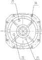
图2是图1的右视放大示意图;Fig. 2 is a right enlarged schematic diagram of Fig. 1;
图3是图1的局部剖视放大示意图;Fig. 3 is a partial cross-sectional enlarged schematic diagram of Fig. 1;
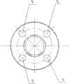
图4是图1的左视放大示意图;Fig. 4 is a left enlarged schematic diagram of Fig. 1;
图5是本发明的用于离心泵的流体测试实验装置(即图1+管路系统)的实际使用状态示意图。Fig. 5 is a schematic diagram of the actual use state of the fluid test experimental device (ie, Fig. 1 + piping system) for a centrifugal pump of the present invention.
具体实施方式Detailed ways
图1~图5结合给出了一种用于离心泵的流体测试实验装置,其由测试系统及管路系统组成。Figures 1 to 5 combine to provide a fluid testing experimental device for a centrifugal pump, which consists of a testing system and a piping system.
测试系统包括泵壳3和贯穿泵壳3的主轴1。泵壳3的内腔由大小两个相连通的空腔组成,大小空腔的交界面称为左端面31,大空腔位于小空腔的右侧。泵壳3的大空腔由左端面31和大空腔侧壁32围合形成;泵壳3的右侧端盖与法兰设计成一体,从而形成端盖法兰6,此端盖法兰6依靠螺栓与大空腔侧壁32的右端面固定相连。在左端面31上设有定位凸台29,此定位凸台29位于泵壳3的大空腔内。泵壳3的小空腔由底面33、小空腔侧壁和左端面31围合形成,在小空腔侧壁上设有泄漏流出口22,在底面33上设有后眼回流口23。The test system includes a
主轴1的左半段位于泵壳3的外部,主轴1的右半段依次穿越底面33和左端面31位于泵壳3的内腔中(即主轴1的右半段小部分位于泵壳3的小空腔内、大部分位于泵壳3的大空腔内),在主轴1的右端面设有与叶轮11上的螺母15相吻合的螺栓。The left half of the
该端盖法兰6的四侧面均设有用于PIV测试的通孔35,套装在端盖法兰6内腔中的透明盖板5堵塞上述用于PIV测试的通孔35;此透明盖板5采用机玻璃制成,靠泵壳3实现定位。实际加工时,端盖法兰6上除保留沿对角线四个方向用于与泵壳3的定位(即,与泵壳3侧壁的相连),上下左右四个方向均削平自然形成了上述通孔35,从而露出位于端盖法兰6内的透明盖板5。进行PIV测试时,激光光源可沿端盖法兰6的四侧面的通孔35,从四个方向入射并透过透明盖板5进入泄漏流道8。The four sides of the
在泵壳3的大空腔内分别设有叶轮11和导叶4,套装在主轴1右半段上的叶轮11被导叶4所包围(导叶4和叶轮11间不接触);该导叶4的右端面与大空腔侧壁32的右端面相齐平。实际安装方式为:去除端盖法兰6后,将导叶4、叶轮11及透明盖板5依序由泵壳3的右端装于泵壳3的大空腔内;当导叶4与定位凸台29相接触后,导叶4就不能再向左移动了;在导叶4和定位凸台29之间设置密封圈30;依靠螺母15与位于主轴1右端面的螺栓的连接,叶轮11与主轴1实现相连,从而限制了叶轮11的轴向运动,且叶轮11与主轴1之间为过盈配合;当透明盖板5与导叶4的右端面与大空腔侧壁32的右端面同时接触时,透明盖板5就不能再向左移动了。在透明盖板5与大空腔侧壁32的右端面之间设置密封圈28;最后再装上端盖法兰6;此时,透明盖板5位于端盖法兰6的内腔中。依靠端盖法兰6、透明盖板5、导叶4和定位凸台29的依次相互紧压,从而确保透明盖板5和导叶4与泵壳3之间的定位。这样,就将叶轮11封于泵壳3内;透明盖板5与叶轮11间沿径向形成泄漏流道8。端盖法兰6内设有4条相互交叉垂直且均通过端盖法兰6中心的筋板36;由于端盖法兰6上除保留沿对角线四个方向用于与泵壳3的定位外,上下左右四个方向均削平;因此端盖法兰6的外圈和内圈间由筋板36连接。筋板36在支撑透明盖板5的同时将透明盖板5沿环向均分为四个区域,分别预留作压力传感器及电涡流位移传感器7的安装空间及PIV测试的观测空间。透明盖板5上除PIV测试区外,其他三个区域分别各设有一个与泄漏流道8相连通的泄压孔25。实际使用时,这三个泄压孔25均分别各接一个压力传感器,从而实现压力传感器通过透明盖板5上的泄压孔25与泄漏流道8相连通,压力传感器用于泄漏流道8内流场的测试。如果实际实验时无需使用压力传感器,那么一定要用塞子堵住此泄压孔25,避免发生泄露。The
在端面法兰6左侧内表面装有密封外口环9,密封外口环9与过盈装在叶轮11上的内口环10形成口环间隙,工作状态下口环间隙两侧具有一定压差,由此处泄漏的介质重回到叶轮11出口。端盖法兰6上沿环向相互垂直方向开有四个φ10螺纹通孔用于安装2个相互垂直的电涡流位移传感器7,端盖法兰6与电涡流位移传感器7间的密封通过O型圈34实现。电涡流位移传感器7的头部位于密封外口环9和内口环10之间的口环间隙内,电涡流位移传感器7用于口环间隙的测试。The inner surface of the left side of the
在泵壳3的左端面31(即泵壳3的背面)上均匀设有4个轴对称布置的出口16,目的是为了尽可能抵消流体经蜗壳产生的径向力对测试结果的影响。工作时介质经叶轮11由导叶4到达泵壳3的4个出口16,然后进入管路系统中的出流管路43。导叶4上存在着由叶轮11的出口至出口16的径向通道,从而将叶轮11内的介质引入出口16;该内容为常规技术,为了图面的清晰,该径向通道在图1中未显示。On the
在主轴1和泵壳3的左端面31之间设置密封盘组件;该密封盘组件由均套装在主轴1上的主密封盘20和副密封盘21组成,主轴1能带动主密封盘20和副密封盘21作旋转;在左端面31与主轴1之间设置主密封盘20,在底面33与主轴1之间设置副密封盘21,即主密封盘20与副密封盘21依序装于主轴1上的叶轮11后部;主密封盘20、左端面31、副密封盘21、底面33、小空腔侧壁围合形成的空间为泄漏腔24(即为小空腔)。在小空腔侧壁上设有与泄漏腔24相连通的泄漏出口22。A sealing disc assembly is arranged between the
主密封盘20与左端面31及导叶4之间存在1~2mm的间隙,副密封盘21与底面33之间存在1~2mm的间隙;上述间隙的作用是因部件间的相对转动形成间隙密封以减小泄露。实际工作时,叶轮11背面泄露主要靠主密封盘20与上述静部件之间的相对运动实现密封,少量的由主密封盘20与左端面31之间的间隙进入泄漏腔24的泄漏油可经泄漏流出口22引出。若有飞溅介质进入副密封盘21与底面33之间的间隙,可依靠副密封盘21实现二次密封,介质被甩到底面33后经后眼回流口23流回泄漏腔24,从而可对动态力传感器12起到保护作用。There is a gap of 1-2mm between the
在主轴1的左半段上分别设有动态力传感器12以及与主轴1同轴心的导电滑环13,导电滑环13由位于内层的动环和位于外层的静环组成,导电滑环13的动环与动态力传感器12通过数据线相连并随主轴1一起旋转,导电滑环13的静环相对泵壳3静止并通过导线将数据引出。保护罩2经螺栓连接于泵壳3上,保护罩2一方面用于保护位于其内部的动态力传感器12及导电滑环13,另一方面可收集经由叶轮11后端面泄漏的介质(即穿越主密封盘20和副密封盘21的泄露介质)使其沿保护罩2下端流出而不会发生飞溅。保护罩2左端开有长槽,方便导电滑环13上定位螺栓14的安装;定位螺栓14的作用是限制导电滑环13的静环产生转动。On the left half of the
上述主密封盘20和副密封盘21的设计是为了保证所测流体力准确性并满足了叶轮11偏心可调时的密封要求,叶轮11背面无轴向密封,而是通过主密封盘20和副密封盘21与泵壳3及导叶4间的径向间隙保证密封,少量泄漏进入泄漏腔24后经泄漏流出口22引出。泵壳3设置轴对称的多出口(4个出口16)平衡径向力,尽量减少干扰因素对测试结果的影响;透明盖板5全透明设计,其与泵壳3及端盖法兰6配合可满足PIV测试的要求;端盖法兰6采用盖板及法兰一体设计以方便拆卸,可满足叶轮11及密封外口环9的频繁更换的要求;安装在端盖法兰6上的相互垂直的两个电涡流位移传感器7可实现口环间隙的实时监测,为实验数据的处理提供帮助;透明盖板5与泵壳3间采用轴向密封,可避免遮挡住侧面激光光源入射从而干扰到PIV测试。The design of the above-mentioned
管路系统包括加压泵40、水箱41、进流管路I42、出流管路43、进流管路II44、阀门I45、阀门II46和引流管47。水箱41通过进流管路I42与端盖法兰6的入口(即端盖法兰6的右端)相连,位于泵壳3左端面上的4个出口16均通过出流管路43与水箱41相连,所述水箱41通过进流管路II44与加压泵40相连,加压泵40通过引流管47与出流管路43相连通;在出流管路43上设有阀门I45,在引流管47上设有阀门II46。The piping system includes a
本发明的流体力测试实验装置实际使用时,主轴1的左端经法兰与动力装置连接。如图1所示,分为以下2种情况:When the fluid force testing experimental device of the present invention is actually used, the left end of the
1、正向正常水泵工况:1. Forward normal water pump working condition:
此工况下,泵壳3内的叶轮11为真实叶轮,此时阀门II46关闭,阀门I45开启,介质由水箱41中经进流管路I42进入图1所示的测试系统,具体如下:Under this working condition, the
介质由端盖法兰6的入口(即端盖法兰6的右端)进入泵壳3的大空腔中,在高速旋转的叶轮11的作用下,依次经叶轮11、导叶4及泵壳3内腔到达位于泵壳3左端面31的4个出口16,然后在加压后由泵壳3上的4个出口16流出经由出流管路43流入水箱41,形成循环管路。The medium enters the large cavity of the
此工况下,加压泵40不起作用。Under this working condition, the
各种监测数据的测试情况如下:The test conditions of various monitoring data are as follows:
随着叶轮11转速的上升,动态力传感器12可测得叶轮11上所受流体激振力的变化情况,电涡流位移传感器7可通过测量内口环10的位移变化实现对口环间隙的实时监测。如需获得泄露流道内部的压力分布,需通过在透明盖板5上的泄压孔25安装压力传感器测得,泄露流道8内部流场的观测可通过通孔35(作为激光入射通道)及透明盖板5上预留的观测区域结合PIV测试装置完成。可通过更换叶轮11及外口环9获得不同工况下的上述数据。With the increase of the speed of the
2、反向手动加压工况,只针对口环进行,适用于无实物叶轮的情况:2. In the reverse manual pressurization condition, it is only for the mouth ring, and it is suitable for the situation without a physical impeller:
在不考虑叶轮11内部结构,只针对口环处(密封外口环9和内口环10组成)流体力进行测试的情况下;叶轮11用实心叶轮进行替换。此时阀门I45关闭,阀门II46开启,介质由水箱41中引出经进流管路II44进入加压泵40,加压后的介质依次经引流管47、出流管路43进入图1所示的测试系统,具体如下:Without considering the internal structure of the
介质由位于泵壳3左端面31的4个出口16进入泵壳3的大空腔中,在高速旋转的实心叶轮的作用下,依次经出口16、泵壳3内腔、导叶4及泄漏流道8到达端盖法兰6的入口(即端盖法兰6的右端),最后经进流管路I42流入水箱41中,形成循环管路。The medium enters the large cavity of the
各种监测数据的测试情况如下:The test conditions of various monitoring data are as follows:
在此工况下,各组数据的测试手段与前一工况相同。只是由于不考虑叶轮11内部结构,因此只通过更换内口环10来观察不同口环情况下叶轮11所受流体激振力的变化情况。In this working condition, the test means of each set of data are the same as the previous working condition. Only because the internal structure of the
最后,还需要注意的是,以上列举的仅是本发明的一个具体实施例。显然,本发明不限于以上实施例,还可以有许多变形。本领域的普通技术人员能从本发明公开的内容直接导出或联想到的所有变形,均应认为是本发明的保护范围。Finally, it should also be noted that what is listed above is only a specific embodiment of the present invention. Obviously, the present invention is not limited to the above embodiments, and many variations are possible. All deformations that can be directly derived or associated by those skilled in the art from the content disclosed in the present invention should be considered as the protection scope of the present invention.
Claims (6)
Translated fromChinesePriority Applications (1)
| Application Number | Priority Date | Filing Date | Title |
|---|---|---|---|
| CN2010101904359ACN101846086B (en) | 2010-06-03 | 2010-06-03 | A fluid testing experimental device for a centrifugal pump |
Applications Claiming Priority (1)
| Application Number | Priority Date | Filing Date | Title |
|---|---|---|---|
| CN2010101904359ACN101846086B (en) | 2010-06-03 | 2010-06-03 | A fluid testing experimental device for a centrifugal pump |
Publications (2)
| Publication Number | Publication Date |
|---|---|
| CN101846086A CN101846086A (en) | 2010-09-29 |
| CN101846086Btrue CN101846086B (en) | 2012-02-22 |
Family
ID=42770842
Family Applications (1)
| Application Number | Title | Priority Date | Filing Date |
|---|---|---|---|
| CN2010101904359AExpired - Fee RelatedCN101846086B (en) | 2010-06-03 | 2010-06-03 | A fluid testing experimental device for a centrifugal pump |
Country Status (1)
| Country | Link |
|---|---|
| CN (1) | CN101846086B (en) |
Families Citing this family (14)
| Publication number | Priority date | Publication date | Assignee | Title |
|---|---|---|---|---|
| CN102183356B (en)* | 2011-03-17 | 2012-11-14 | 哈尔滨工程大学 | Device for testing fluid friction resistance |
| CN103047124B (en)* | 2011-10-12 | 2015-09-23 | 中国石油化工股份有限公司 | Multifunction test device is measured in centrifugal pump external characteristics and internal flow |
| CN102678580B (en)* | 2012-05-31 | 2014-10-15 | 张家港市恩达泵业有限公司 | Multistage submerged pump sealing structure |
| CN103062075B (en)* | 2012-11-09 | 2015-06-10 | 江苏大学 | Device and method for particle image velocimetry (PIV) error measurement and demarcation of centrifugal pump |
| CN104314839A (en)* | 2014-08-21 | 2015-01-28 | 江苏大学 | Centrifugal pump experiment table for particle picture velocimetry |
| CN105784231B (en)* | 2016-03-11 | 2019-01-25 | 上海交通大学 | Apparatus and method for measuring radial pressure, flow resistance and asymmetric axial force of annular flow in disc surface gap with return hole |
| CN107100886B (en)* | 2017-03-24 | 2018-11-09 | 江苏大学 | The blade wheel structure of mixed-flow pump blade rim exciting force under a kind of measurable Alford effects |
| CN108414211B (en)* | 2018-05-16 | 2023-07-14 | 浙江理工大学 | Experimental bench device and experimental method for testing the characteristics of the excitation force of the front cover plate gap of the centrifugal pump |
| CN108678971B (en)* | 2018-07-17 | 2024-05-07 | 浙江工业大学 | Centrifugal pump mouth annular gap flow experimental device |
| CN109296566A (en)* | 2018-09-28 | 2019-02-01 | 西安理工大学 | Observation device for gas and liquid flow inside centrifugal pump |
| CN111852886A (en)* | 2019-04-30 | 2020-10-30 | 山东亨泉能源科技有限公司 | A sealless high-efficiency single-stage coaxial centrifugal pump |
| CN112879621B (en)* | 2021-02-09 | 2023-01-17 | 国家石油天然气管网集团有限公司华南分公司 | A gear motor composite servo motor dual-mode guided safety Y-type water hammer pressure relief valve |
| CN114216065B (en)* | 2021-12-27 | 2023-08-22 | 大连华锐重工集团股份有限公司 | Hydraulic slip ring leakage state monitoring system and method |
| CN116242560B (en)* | 2023-05-10 | 2023-08-04 | 兰州理工大学 | Centrifugal pump impeller seal ring clearance test device and test method |
Family Cites Families (3)
| Publication number | Priority date | Publication date | Assignee | Title |
|---|---|---|---|---|
| US5383351A (en)* | 1993-11-12 | 1995-01-24 | Atlantic Richfield Company | Pump seal test apparatus and method |
| RU2065088C1 (en)* | 1994-01-12 | 1996-08-10 | Людмила Константиновна Клейменова | Method of separation of delivery and inlet chambers of spiral housing of centrifugal pump in conducting hydraulic tests |
| CN101419242B (en)* | 2008-11-05 | 2010-08-11 | 浙江科尔泵业股份有限公司 | Test method for critical speed of centrifugal pump and test device thereof |
- 2010
- 2010-06-03CNCN2010101904359Apatent/CN101846086B/ennot_activeExpired - Fee Related
Also Published As
| Publication number | Publication date |
|---|---|
| CN101846086A (en) | 2010-09-29 |
Similar Documents
| Publication | Publication Date | Title |
|---|---|---|
| CN101846086B (en) | A fluid testing experimental device for a centrifugal pump | |
| RU98498U1 (en) | SUBMERSIBLE CENTRIFUGAL PUMP FOR PUMPING AGGRESSIVE LIQUIDS | |
| CN106246559B (en) | A double-body double-suction canned pump | |
| CN108087291B (en) | High-lift long-blade molded line rear cavity structure centrifugal pump | |
| CN106678056B (en) | A kind of general-purpose centrifugal pump choma testing stand | |
| CN202789561U (en) | Axial flow pump used for velocity measurement for particle picture | |
| CN107939743A (en) | A kind of cooling centrifugal pump certainly | |
| CN110645189A (en) | A kind of testing device and method for liquid leakage of impeller balance hole of centrifugal pump | |
| CN110805514A (en) | A pressure relief and drainage device for the top cover of a horizontal Francis turbine | |
| CN107100886B (en) | The blade wheel structure of mixed-flow pump blade rim exciting force under a kind of measurable Alford effects | |
| CN108036033B (en) | High-strength transparent fluid coupling device for PIV testing | |
| CN201636067U (en) | Axial force balance device of ultra-deep well submersible pump | |
| CN114576068B (en) | A hydraulic turbine convenient for real-time status monitoring | |
| CN103512685B (en) | Sealing force testing device used for studying damping seal prerotation effect | |
| CN106907337A (en) | The Research on Testing System of Thrust on Aluminum and method of canned motor pump | |
| CN101149321B (en) | Liquid-solid two-phase flow erosion and cavitation composite wear testing machine | |
| CN116242560B (en) | Centrifugal pump impeller seal ring clearance test device and test method | |
| CN202520959U (en) | Water turbine spindle sealing device | |
| Glovatskii et al. | Experimental tests of submersible vane pumps | |
| CN216788497U (en) | Mounting device for eddy current probe of turbine moving blade state characteristic monitoring system | |
| CN206723078U (en) | The Research on Testing System of Thrust on Aluminum of canned motor pump | |
| CN212536098U (en) | Motor-driven auxiliary water supply steam-driven pump test system | |
| CN211121714U (en) | A new type of high-speed hydraulic dynamometer | |
| RU202319U1 (en) | CENTRIFUGAL PUMP WITH PLANE BODY CONNECTOR, PARALLEL SHAFT AXIS | |
| Nishida et al. | Shear evaluation by quantitative flow visualization near the casing surface of a centrifugal blood pump |
Legal Events
| Date | Code | Title | Description |
|---|---|---|---|
| C06 | Publication | ||
| PB01 | Publication | ||
| C10 | Entry into substantive examination | ||
| SE01 | Entry into force of request for substantive examination | ||
| C14 | Grant of patent or utility model | ||
| GR01 | Patent grant | ||
| C17 | Cessation of patent right | ||
| CF01 | Termination of patent right due to non-payment of annual fee | Granted publication date:20120222 Termination date:20140603 |