CN101844307A - Redundancy-driven three-degree-of-freedom parallel mechanism - Google Patents
Redundancy-driven three-degree-of-freedom parallel mechanismDownload PDFInfo
- Publication number
- CN101844307A CN101844307ACN 201010165567CN201010165567ACN101844307ACN 101844307 ACN101844307 ACN 101844307ACN 201010165567CN201010165567CN 201010165567CN 201010165567 ACN201010165567 ACN 201010165567ACN 101844307 ACN101844307 ACN 101844307A
- Authority
- CN
- China
- Prior art keywords
- moving
- pair
- platform
- fixed platform
- driven
- Prior art date
- Legal status (The legal status is an assumption and is not a legal conclusion. Google has not performed a legal analysis and makes no representation as to the accuracy of the status listed.)
- Granted
Links
Images

Landscapes
- Transmission Devices (AREA)
Abstract
Description
Translated fromChinese技术领域technical field
本发明属于机械制造领域,特别涉及一种能够应用于数控装置制造领域的一种模块化的驱动冗余三自由度并联机构。The invention belongs to the field of mechanical manufacturing, and in particular relates to a modular drive redundant three-degree-of-freedom parallel mechanism that can be applied to the field of numerical control device manufacturing.
背景技术Background technique
并联机构是由多个支链构成的闭环机构,相对于传统的串联机构具有以下优点:The parallel mechanism is a closed-loop mechanism composed of multiple branch chains. Compared with the traditional series mechanism, it has the following advantages:
结构简单紧凑、刚度高、单位重量上承载能力大、无误差积累、运动部件质量小、易于实现高速运动等优点。这些优点在一定程度上弥补了传统数控装置的不足。然而,并联机构也有其天生的缺陷,尤其是6自由度并联机构,其运动耦合性强、工作空间小、运动学正解复杂、工作空间不规则、数控编程复杂,等等。这些缺点增加了控制和后续的标定工作的复杂性,从而使得并联机构的推广应用受到了较大程度的限制。It has the advantages of simple and compact structure, high rigidity, large bearing capacity per unit weight, no error accumulation, small mass of moving parts, and easy realization of high-speed movement. These advantages make up for the shortcomings of traditional numerical control devices to a certain extent. However, the parallel mechanism also has its inherent defects, especially the 6-DOF parallel mechanism, which has strong kinematic coupling, small working space, complex kinematics forward solution, irregular working space, and complicated NC programming, etc. These shortcomings increase the complexity of the control and subsequent calibration work, which limits the popularization and application of parallel mechanisms to a greater extent.
近年来,少自由度并联机构(自由度数少于六自由度的并联机构)越来越受到研究者的重视和青睐,。一些少自由度并联装置已经得到了成功应用,如德国DS Technologie公司研制的Sprint Z3三自由度并联主轴头在数控加工中心中获得了巨大的成功。该主轴头作为数控加工中心的一个模块,实现一个移动和两个转动自由度。该类机构的特点是:容易实现加工模块化、运动学简单、具有解耦或者部分解耦的特性。运动解耦的机构容易控制,并且可以达到更高的运动精度,并且解耦运动对机构的运动控制和轨迹规划都有一定意义。In recent years, parallel mechanisms with less degrees of freedom (parallel mechanisms with less than six degrees of freedom) have attracted more and more attention and favor from researchers. Some parallel devices with few degrees of freedom have been successfully applied. For example, the Sprint Z3 three-degree-of-freedom parallel spindle head developed by DS Technologie in Germany has achieved great success in CNC machining centers. As a module of the CNC machining center, the spindle head realizes one movement and two rotation degrees of freedom. The characteristics of this type of mechanism are: it is easy to realize the modularization of processing, the kinematics is simple, and it has the characteristics of decoupling or partial decoupling. The motion decoupled mechanism is easy to control and can achieve higher motion precision, and the decoupled motion has certain significance for the motion control and trajectory planning of the mechanism.
本发明所提出的机构也同属于少自由度并联机构中的三自由度并联机构。The mechanism proposed by the present invention also belongs to the three-degree-of-freedom parallel mechanism in the parallel mechanism with few degrees of freedom.
为了进一步克服并联机构的一些缺点,比如工作空间小以及工作空间不规则等,常采用添加冗余驱动的方式,利用冗余特性来避免机构的奇异,从而增大原有机构的工作空间,同时达到提高其刚度和精度的目的,这样构成的机构即为驱动冗余的并联机构。本发明所提出的机构即为驱动冗余的三自由度并联机构。In order to further overcome some shortcomings of the parallel mechanism, such as small working space and irregular working space, etc., the way of adding redundant drives is often adopted, and the redundant characteristics are used to avoid the singularity of the mechanism, thereby increasing the working space of the original mechanism, and at the same time achieving For the purpose of improving its rigidity and precision, the mechanism thus constituted is a parallel mechanism with drive redundancy. The mechanism proposed by the present invention is a three-degree-of-freedom parallel mechanism with drive redundancy.
发明内容Contents of the invention
本发明的目的是为克服已有技术的不足之处,提出一种驱动冗余三自由度并联机构,本发明通过冗余驱动的添加,该机构在具备了一般三自由度并联机构的优点的同时,其刚度和精度都得到了进一步的提高。The purpose of the present invention is to overcome the deficiencies of the prior art, and propose a drive redundant three-degree-of-freedom parallel mechanism, the present invention through the addition of redundant drive, this mechanism possesses the advantages of the general three-degree-of-freedom parallel mechanism At the same time, its stiffness and precision have been further improved.
本发明提出的一种驱动冗余三自由度并联机构,包括一个安装执行器的动平台和定平台,以及连接所述动平台和定平台之间的具有相同结构的第一、第二支链;该第一、第二支链均含有一个主动驱动的运动副;其特征在于:该装置还包含一个含有冗余驱动的第三支链,用于实现转动自由度,且冗余驱动施加在该支链的移动副上;该支链中有两个运动副是被驱动的,该第三支链连接于动平台和定平台之间;所述第一、第二和第三支链分别与定平台以及动平台连接形成一个空间并联闭环机构,该空间并联闭环机构通过四个输入运动驱动动平台运动,实现两个移动自由度和一个转动自由度。A drive redundant three-degree-of-freedom parallel mechanism proposed by the present invention includes a moving platform and a fixed platform on which actuators are installed, and first and second branch chains with the same structure connecting the moving platform and the fixed platform ; Both the first and second branch chains contain an actively driven kinematic pair; it is characterized in that: the device also includes a third branch chain containing a redundant drive, which is used to realize the degree of freedom of rotation, and the redundant drive is applied to On the moving pair of the branch chain; two moving pairs are driven in the branch chain, and the third branch chain is connected between the moving platform and the fixed platform; the first, second and third branch chains are respectively It is connected with the fixed platform and the moving platform to form a space parallel closed-loop mechanism. The space parallel closed-loop mechanism drives the movement of the moving platform through four input motions to realize two degrees of freedom of movement and one degree of freedom of rotation.
本发明的特点及技术效果Features and technical effects of the present invention
本发明的机构通过在实现转动的运动学支链上的移动副添加一个冗余驱动,由四个输入驱动动平台运动,实现两个移动自由度和一个转动自由度。动平台可实现较大的转动输出是该机构的一个突出优点,克服了以往并联机构转动能力有限的缺点。通过冗余驱动的添加,该机构在具备了一般三自由度并联机构的优点的同时,其刚度和精度都得到了进一步的提高,更容易实现模块化。The mechanism of the present invention adds a redundant drive to the moving pair on the kinematic branch chain that realizes rotation, and drives the moving platform to move by four inputs, so as to realize two degrees of freedom of movement and one degree of freedom of rotation. It is a prominent advantage of this mechanism that the moving platform can realize a larger rotation output, which overcomes the shortcomings of the limited rotation capacity of the previous parallel mechanism. With the addition of redundant drives, the mechanism has the advantages of a general three-degree-of-freedom parallel mechanism, while its stiffness and precision have been further improved, and it is easier to achieve modularization.
该冗余机构具有以下优点:(1)机构简单、紧凑;(2)刚度高;(3)工作空间大,尤其是转动工作空间,转动能力可达115°。这些优点使得该机构灵活性更好、加工精度更高,更容易实现模块化,配合其它装置可实现对复杂自由曲面类零件的多轴联动数控加工。The redundant mechanism has the following advantages: (1) the mechanism is simple and compact; (2) the rigidity is high; (3) the working space is large, especially the rotating working space, and the rotating capacity can reach 115°. These advantages make the mechanism more flexible, higher machining accuracy, easier to realize modularization, and cooperate with other devices to realize multi-axis linkage CNC machining of complex free-form surface parts.
附图说明Description of drawings
图1为本发明实施例1的结构示意图。Fig. 1 is a schematic structural diagram of
图2为本发明实施例2的结构示意图。Fig. 2 is a schematic structural diagram of Embodiment 2 of the present invention.
图3为本发明实施例3的结构示意图。Fig. 3 is a schematic structural diagram of Embodiment 3 of the present invention.
图4为本发明实施例4的结构示意图。Fig. 4 is a schematic structural diagram of Embodiment 4 of the present invention.
图5为本发明中采用的伸缩杆式驱动支链的结构示意图。Fig. 5 is a structural schematic diagram of the telescopic rod type driving branch chain adopted in the present invention.
具体实施方式Detailed ways
本发明的驱动冗余三自由度并联机构结合附图及实施例详细说明如下:The drive redundant three-degree-of-freedom parallel mechanism of the present invention is described in detail as follows in conjunction with the accompanying drawings and embodiments:
本发明提出的一种驱动冗余三自由度并联机构,包括一个安装执行器的动平台和定平台,以及连接所述动平台和定平台之间的具有相同结构的第一、第二支链;该第一、第二支链均含有一个主动驱动的运动副;其特征在于:该装置还包含一个含有冗余驱动的第三支链,用于实现转动自由度,且冗余驱动施加在该支链的移动副上;该支链中有两个运动副是被驱动的,该第三支链连接于动平台和定平台之间;所述第一、第二和第三支链分别与定平台以及动平台连接形成一个空间并联闭环机构,该空间并联闭环机构通过四个输入运动驱动动平台运动,实现两个移动自由度和一个转动自由度。A drive redundant three-degree-of-freedom parallel mechanism proposed by the present invention includes a moving platform and a fixed platform on which actuators are installed, and first and second branch chains with the same structure connecting the moving platform and the fixed platform ; Both the first and second branch chains contain an actively driven kinematic pair; it is characterized in that: the device also includes a third branch chain containing a redundant drive, which is used to realize the degree of freedom of rotation, and the redundant drive is applied to On the moving pair of the branch chain; two moving pairs are driven in the branch chain, and the third branch chain is connected between the moving platform and the fixed platform; the first, second and third branch chains are respectively It is connected with the fixed platform and the moving platform to form a space parallel closed-loop mechanism. The space parallel closed-loop mechanism drives the movement of the moving platform through four input motions to realize two degrees of freedom of movement and one degree of freedom of rotation.
本发明的机构,第一、第二支链可以是PRRR型或PRU型或PRS型运动支链也可以是RPRR型或RPU型或RPS型运动支链,第三支链可以是PPRR型或者PRPR型运动支链。其中,P代表移动副,R代表转动副,U代表虎克铰,S代表球铰,且移动副P是驱动运动副。具体说明如下:In the mechanism of the present invention, the first and second branch chains can be PRRR type or PRU type or PRS type motion branch chains and can also be RPRR type or RPU type or RPS type motion branch chains, and the third branch chain can be PPRR type or PRPR type sports chain. Among them, P represents the moving joint, R represents the rotating joint, U represents the Hooke joint, S represents the spherical joint, and the moving joint P is the driving kinematic joint. The specific instructions are as follows:
第一、第二支链可包括:滑块、连杆、U型架以及运动副。所述运动副有四个,一个是连接于定平台和滑块之间的移动副(P),一个是连接于滑块和连杆之间的转动副(R),一个是连接于连杆和U型架之间的转动副(R),另一个是连接于U型架和动平台之间的转动副(R)。其中,连接于定平台和滑块之间的移动副(P)是被驱动的,连接于连杆和U型架之间的转动副(R)和连接于U型架和动平台之间的转动副(R)是相互垂直的,且这两个转动副可由一个虎克铰(U)或者一个球铰(S)代替,该支链为PRRR型运动支链或PRU型运动支链或PRS型运动支链。The first and second branch chains may include: a slider, a connecting rod, a U-shaped frame and a kinematic pair. There are four kinematic pairs, one is a moving pair (P) connected between the fixed platform and the slider, one is a rotating pair (R) connected between the slider and the connecting rod, and one is connected to the connecting rod and the revolving pair (R) between the U-shaped frame, and the other is the revolving pair (R) connected between the U-shaped frame and the moving platform. Among them, the moving pair (P) connected between the fixed platform and the slider is driven, the rotating pair (R) connected between the connecting rod and the U-shaped frame and the rotating pair (R) connected between the U-shaped frame and the moving platform The revolving pairs (R) are perpendicular to each other, and these two revolving pairs can be replaced by a Hooke hinge (U) or a spherical hinge (S), the branch chain is a PRRR type motion branch chain or a PRU type motion branch chain or a PRS type sports chain.
第一、第二支链还可包括:外伸缩杆、内伸缩杆、U型架以及运动副。所述运动副有四个,一个是连接于定平台和外伸缩杆之间的转动副(R),一个是连接于外伸缩杆和内伸缩杆之间的转动副(P),一个是连接于内伸缩杆和U型架之间的转动副(R),另一个是连接于U型架和动平台之间的转动副(R)。其中,连接于外伸缩杆和内伸缩杆之间的转动副(P)是被驱动的,连接于连杆和U型架之间的转动副(R)和连接于U型架和动平台之间的转动副(R)是相互垂直的,且这两个转动副可由一个虎克铰(U)或者一个球铰(S)代替,该支链为RPRR型运动支链或RPU型运动支链或RPS型运动支链。The first and second branch chains may also include: an outer telescopic rod, an inner telescopic rod, a U-shaped frame and a kinematic pair. There are four kinematic pairs, one is a rotating pair (R) connected between the fixed platform and the outer telescopic rod, one is a rotating pair (P) connected between the outer telescopic rod and the inner telescopic rod, and one is connected to the The revolving pair (R) between the inner telescopic rod and the U-shaped frame, and the other is the revolving pair (R) connected between the U-shaped frame and the moving platform. Among them, the rotating pair (P) connected between the outer telescopic rod and the inner telescopic rod is driven, and the rotating pair (R) connected between the connecting rod and the U-shaped frame and the U-shaped frame and the moving platform are connected. The revolving pairs (R) between them are perpendicular to each other, and these two revolving pairs can be replaced by a Hooke hinge (U) or a spherical hinge (S), and the branch chain is a RPRR type motion branch chain or an RPU type motion branch chain Or RPS type sports chain.
第三支链可包括:滑台、滑块、连杆以及运动副。所述运动副有四个,一个是连接于定平台和滑台之间的移动副(P),一个是连接于滑台和滑块之间的移动副(P),一个是连接于滑块和连杆之间的转动副(R),另一个是连接于连杆和动平台之间的转动副(R)。其中,连接于定平台和滑台之间的移动副(P)和连接于滑台和滑块之间的移动副(P)是被驱动的,该支链为PPRR型运动支链。The third branch chain may include: a sliding table, a sliding block, a connecting rod and a kinematic pair. There are four kinematic pairs, one is a moving pair (P) connected between the fixed platform and the slide table, one is a moving pair (P) connected between the slide table and the slider, and one is connected to the slider and the rotary joint (R) between the connecting rod and the other is the rotary joint (R) connected between the connecting rod and the moving platform. Among them, the moving pair (P) connected between the fixed platform and the slide table and the moving pair (P) connected between the slide table and the slider are driven, and the branch chain is a PPRR type motion branch chain.
第三支链还可包括:滑台、外伸缩杆、内伸缩杆以及运动副。所述运动副有四个,一个是连接于定平台和滑台之间的移动副(P),一个是连接于滑台和外伸缩杆之间的转动副(R),一个是连接于外伸缩杆和内伸缩杆之间的移动副(P),另一个是连接于内伸缩杆和动平台之间的转动副(R)。其中,连接于定平台和滑台之间的移动副(P)和连接于外伸缩杆和内伸缩杆之间的移动副(P)是被驱动的,该支链为PRPR型运动支链。The third branch chain can also include: a slide table, an outer telescopic rod, an inner telescopic rod and a kinematic pair. There are four kinematic pairs, one is a moving pair (P) connected between the fixed platform and the sliding table, one is a rotating pair (R) connected between the sliding table and the outer telescopic rod, and one is connected to the outer telescopic rod. The mobile pair (P) between the telescopic rod and the inner telescopic rod, and the other is the rotating pair (R) connected between the inner telescopic rod and the moving platform. Among them, the mobile pair (P) connected between the fixed platform and the slide table and the mobile pair (P) connected between the outer telescopic rod and the inner telescopic rod are driven, and the branch chain is a PRPR type motion branch chain.
实施例1:Example 1:
本实施例的驱动冗余三自由度并联机构的结构如图1所示,包括定平台11、定平台17、定平台112、动平台18及第一、第二、第三支链,所述三条支链分别连接于定平台11、定平台17、定平台112和动平台18之间,并与该平台11、定平台17、定平台112和动平台18构成空间闭环机构。The structure of the drive redundant three-degree-of-freedom parallel mechanism of this embodiment is shown in Figure 1, including a fixed platform 11, a fixed platform 17, a fixed platform 112, a moving platform 18, and first, second, and third branch chains. The three branch chains are respectively connected between the fixed platform 11, the fixed platform 17, the fixed platform 112 and the moving platform 18, and form a space closed-loop mechanism with the platform 11, the fixed platform 17, the fixed platform 112 and the moving platform 18.
所述第一、第二支链为PRRR型运动支链,包括滑块12、滑块16、连杆13、连杆15、U型架14及运动副。所述的运动副有四个,一个是连接于定平台11、定平台17和滑块12、滑块16之间的移动副(P),一个是连接于滑块12、滑块16和连杆13、连杆15之间的转动副(R),一个是连接于连杆13、连杆15和U型架14之间的转动副(R),另一个是连接于U型架14和动平台18之间的转动副(R)。连接于定平台11、定平台17和滑块12、滑块16之间的移动副(P)是被驱动的,且呈对称布置,运动方向相互平行。连接于连杆13、连杆15和U型架14之间的转动副(R)和连接于U型架14和动平台18之间的转动副(R)相互垂直。The first and second branch chains are PRRR type motion branch chains, including slider 12, slider 16, connecting rod 13, connecting rod 15, U-shaped frame 14 and kinematic pairs. There are four kinematic pairs, one is to be connected to the mobile pair (P) between the fixed platform 11, the fixed platform 17 and the slide block 12, the slide block 16, and one is to be connected to the slide block 12, the slide block 16 and the connecting block. The revolving pair (R) between bar 13, connecting rod 15, one is to be connected to the revolving pair (R) between connecting rod 13, connecting rod 15 and U-shaped frame 14, and the other is to be connected to U-shaped frame 14 and The rotary joint (R) between the movable platform 18. The mobile pair (P) connected between the fixed platform 11, the fixed platform 17 and the slider 12, the slider 16 is driven and arranged symmetrically, and the directions of motion are parallel to each other. The rotary pair (R) connected between the connecting rod 13, the connecting rod 15 and the U-shaped frame 14 and the rotary pair (R) connected between the U-shaped frame 14 and the moving platform 18 are perpendicular to each other.
所述第三支链为PPRR型运动支链,用来实现转动自由度,且冗余驱动施加在该支链的移动副上。包括:滑台110、滑块111、连杆19以及运动副。所述运动副有四个,一个是连接于定平台112和滑台110之间的移动副(P),一个是连接于滑台110和滑块111之间的移动副(P),一个是连接于滑块111和连杆19之间的转动副(R),另一个是连接于连杆19和动平台18之间的转动副(R)。其中,连接于定平台112和滑台110之间的移动副(P)是被驱动的,移动方向垂直于连接于定平台11、定平台17和滑块12、滑块16之间的移动副的运动方向且平行于他们所在的平面;连接于滑台110和滑块111之间的移动副(P)是被驱动的,移动方向平行于连接于定平台11、定平台17和滑块12、滑块16之间的移动副的运动方向。The third branch chain is a PPRR type kinematic branch chain, which is used to realize the degree of freedom of rotation, and the redundant drive is applied to the moving pair of the branch chain. Including: slide table 110, slide block 111, connecting rod 19 and kinematic pair. There are four kinematic pairs, one is a mobile pair (P) connected between the fixed platform 112 and the slide table 110, one is a mobile pair (P) connected between the slide table 110 and the slide block 111, and one is The revolving pair (R) that is connected between the slide block 111 and the connecting rod 19, and the other is a revolving pair (R) that is connected between the connecting rod 19 and the moving platform 18. Wherein, the mobile pair (P) that is connected between the fixed platform 112 and the slide table 110 is driven, and the moving direction is perpendicular to the mobile pair connected between the fixed platform 11, the fixed platform 17 and the slide block 12, the slide block 16. The direction of motion is parallel to their plane; the moving pair (P) connected between the slide table 110 and the slide block 111 is driven, and the movement direction is parallel to the fixed platform 11, the fixed platform 17 and the slide block 12 , The direction of motion of the moving pair between the sliders 16.
实施例2:Example 2:
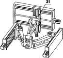
本实施例的驱动冗余三自由度并联机构的结构如图2所示,该机构与实施例1的不同之处在于滑台21的放置方向与实施例1中的滑台110的放置方向相互垂直,此时,滑台21上的移动副的方向与实施例1中的连接于定平台11、定平台17和滑块12、滑块16之间的移动副运动方向所在的平面垂直。The structure of the drive redundant three-degree-of-freedom parallel mechanism of this embodiment is shown in Figure 2. The difference between this mechanism and
实施例3:Example 3:
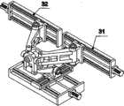
本实施例的驱动冗余三自由度并联机构的结构如图3所示,该机构与实施例1的不同之处在于定平台31和定平台32的放置方向与实施例1中的定平台11和定平台17的放置方向垂直,且定平台31和定平台32上的移动副的运动方向在一条直线上,该直线方向平行于实施例1中的连接于定平台112和滑台110之间的移动副的运动方向。The structure of the drive redundant three-degree-of-freedom parallel mechanism of this embodiment is shown in Figure 3. The difference between this mechanism and
实施例4:Example 4:
本实施例的驱动冗余三自由度并联机构的结构如图4所示,该机构与实施例2的不同之处在于定平台41和定平台42的放置方向与实施例2中相对应的定平台的放置方向垂直,且定平台41和定平台42上的移动副的运动方向在一条直线上,该直线方向平行于实施例2中的滑台21的运动方向。The structure of the drive redundant three-degree-of-freedom parallel mechanism of this embodiment is shown in Figure 4. The difference between this mechanism and Embodiment 2 is that the placement direction of the fixed
以上各实施例所述的第一、第二支链,其驱动方式可由图5所示的伸缩杆式的驱动机构实现,包括:定平台51、外伸缩杆52和内伸缩杆53及运动副,所述运动副有三个,一个是连接于定平台51和外伸缩杆52之间的转动副;一个是连接于外伸缩杆52和内伸缩杆53之间的移动副,且该移动副是被驱动的;另一个是连接于内伸缩杆53和实施例1中U型架14的转动副。The first and second branch chains described in the above embodiments can be driven by the telescopic rod type drive mechanism shown in Figure 5, including: a fixed platform 51, an outer telescopic rod 52, an inner telescopic rod 53 and a kinematic pair , there are three kinematic pairs, one is a rotary pair connected between the fixed platform 51 and the outer telescopic rod 52; one is a movable pair connected between the outer telescopic rod 52 and the inner telescopic rod 53, and the movable pair is Driven; The other is the rotary pair that is connected to the inner telescopic link 53 and the U-shaped frame 14 in
以上各实施例所述的第三支链,其滑块111、连杆19及运动副的驱动方式可由图5所示的伸缩杆式的驱动机构实现,包括:底座51、外伸缩杆52和内伸缩杆53及运动副,所述运动副有三个,一个是连接于底座51和外伸缩杆52之间的转动副;一个是连接于外伸缩杆52和内伸缩杆53之间的移动副,且该移动副是被驱动的;另一个是连接于内伸缩杆53和动平台18的转动副。其中,底座51与滑台110固定连接。The third branch chain described in the above embodiments, the driving mode of its slide block 111, connecting rod 19 and kinematic pair can be realized by the telescopic rod type drive mechanism shown in Figure 5, including: base 51, outer telescopic rod 52 and Inner telescopic rod 53 and kinematic pair, described kinematic pair has three, and one is the rotating pair that is connected between base 51 and outer telescopic rod 52; One is the mobile pair that is connected between outer telescopic rod 52 and inner telescopic rod 53 , and the moving pair is driven; the other is a rotating pair connected to the inner telescopic rod 53 and the moving platform 18. Wherein, the base 51 is fixedly connected with the slide table 110 .
以上各实施例中所述的连接于动平台18和U型架18之间的转动副以及连接于U型架18与连杆13或连杆15或内伸缩杆53之间的转动副可由一个虎克铰或者球铰实现。The rotary pair that is connected between the moving platform 18 and the U-shaped frame 18 described in the above embodiments and the rotary pair that is connected between the U-shaped frame 18 and the connecting rod 13 or the connecting rod 15 or the inner telescopic link 53 can be formed by one Hooke hinge or ball joint realization.
Claims (6)
Priority Applications (1)
| Application Number | Priority Date | Filing Date | Title |
|---|---|---|---|
| CN2010101655676ACN101844307B (en) | 2010-04-30 | 2010-04-30 | A drive redundant three-degree-of-freedom parallel mechanism |
Applications Claiming Priority (1)
| Application Number | Priority Date | Filing Date | Title |
|---|---|---|---|
| CN2010101655676ACN101844307B (en) | 2010-04-30 | 2010-04-30 | A drive redundant three-degree-of-freedom parallel mechanism |
Publications (2)
| Publication Number | Publication Date |
|---|---|
| CN101844307Atrue CN101844307A (en) | 2010-09-29 |
| CN101844307B CN101844307B (en) | 2012-02-22 |
Family
ID=42769218
Family Applications (1)
| Application Number | Title | Priority Date | Filing Date |
|---|---|---|---|
| CN2010101655676AExpired - Fee RelatedCN101844307B (en) | 2010-04-30 | 2010-04-30 | A drive redundant three-degree-of-freedom parallel mechanism |
Country Status (1)
| Country | Link |
|---|---|
| CN (1) | CN101844307B (en) |
Cited By (20)
| Publication number | Priority date | Publication date | Assignee | Title |
|---|---|---|---|---|
| CN101966505A (en)* | 2010-10-15 | 2011-02-09 | 江苏长虹涂装机械有限公司 | Three-degree-of-freedom plane parallel mechanism and spraying robot |
| CN102152300A (en)* | 2011-02-25 | 2011-08-17 | 天津大学 | Linear-driven high-speed planar parallel mechanical arm |
| CN102560603A (en)* | 2012-01-18 | 2012-07-11 | 清华大学 | Automobile coating conveyor with multi-rod mechanisms |
| CN102618906A (en)* | 2012-01-18 | 2012-08-01 | 清华大学 | Gantry type automobile coating conveyor |
| CN103240614A (en)* | 2013-05-06 | 2013-08-14 | 江苏国威工程机械有限公司 | Redundant driving five-axis linkage hybrid machine tool |
| CN103273356A (en)* | 2013-04-28 | 2013-09-04 | 清华大学 | Multi-axis linkage mixed device based on four-freedom-degree parallel mechanism |
| CN105690165A (en)* | 2016-02-03 | 2016-06-22 | 中北大学 | Large-altitude-angle 2R1T three-degree-of-freedom spatial parallel mechanism |
| CN107263451A (en)* | 2017-07-31 | 2017-10-20 | 福州大学 | 2R1T Three Degree Of Freedom Planar Mechanisms parallel institutions and its method of work |
| CN108000495A (en)* | 2017-12-13 | 2018-05-08 | 浙江理工大学 | A kind of two rotations, one movement redundantly actuated parallel mechanism with big swing angle |
| CN108656087A (en)* | 2018-06-12 | 2018-10-16 | 浙江理工大学 | A kind of two rotations, one movement 3-freedom parallel mechanism of driving parallel arrangement |
| CN108789380A (en)* | 2018-08-16 | 2018-11-13 | 西安工程大学 | There are two types of the parallel institutions of 1R1T motor patterns for tool |
| CN109129158A (en)* | 2018-10-30 | 2019-01-04 | 吉林大学 | Accurate milling forming machine tool and its control method based on parallel tool system |
| CN110116400A (en)* | 2019-05-23 | 2019-08-13 | 浙江理工大学 | A kind of PRS-PRU-PUR parallel institution |
| CN110303476A (en)* | 2019-06-28 | 2019-10-08 | 中国航天空气动力技术研究院 | A three-branch three-degree-of-freedom redundant drive type parallel processing head |
| CN111113244A (en)* | 2020-01-08 | 2020-05-08 | 陈海洋 | Polishing equipment for automobile bumper |
| CN112192546A (en)* | 2020-09-11 | 2021-01-08 | 香港理工大学深圳研究院 | Parallel mechanism driven by inner pair and outer pair in combined mode |
| CN113941998A (en)* | 2021-11-25 | 2022-01-18 | 中航空管系统装备有限公司 | Redundant two-degree-of-freedom parallel robot and working method thereof |
| CN114888779A (en)* | 2022-04-29 | 2022-08-12 | 浙江理工大学 | Motion redundancy parallel mechanism with closed-loop subchain in branched chain |
| CN114888780A (en)* | 2022-04-29 | 2022-08-12 | 浙江理工大学 | Three-branch 6+ 3-degree-of-freedom motion redundancy parallel mechanism |
| CN115972299A (en)* | 2022-12-15 | 2023-04-18 | 江苏峰登新材料有限公司 | Drilling equipment is used in processing of XPS extruded sheet |
Citations (3)
| Publication number | Priority date | Publication date | Assignee | Title |
|---|---|---|---|---|
| DE10325999A1 (en)* | 2003-06-10 | 2005-01-05 | Volkswagen Ag | Mounting system for mounting large surface components on a coordinate measurement stand comprises multiple support elements each with a support column, adapter piece and component support means |
| CN1586806A (en)* | 2004-07-22 | 2005-03-02 | 北京航空航天大学 | Two rotation-translation three freedom redundancy parallel mechanism for parallel machine tool |
| CN1586807A (en)* | 2004-07-22 | 2005-03-02 | 北京航空航天大学 | Three freedom redundancy parallel mechanism for realizing two dimension translation and one dimension rotation |
- 2010
- 2010-04-30CNCN2010101655676Apatent/CN101844307B/ennot_activeExpired - Fee Related
Patent Citations (3)
| Publication number | Priority date | Publication date | Assignee | Title |
|---|---|---|---|---|
| DE10325999A1 (en)* | 2003-06-10 | 2005-01-05 | Volkswagen Ag | Mounting system for mounting large surface components on a coordinate measurement stand comprises multiple support elements each with a support column, adapter piece and component support means |
| CN1586806A (en)* | 2004-07-22 | 2005-03-02 | 北京航空航天大学 | Two rotation-translation three freedom redundancy parallel mechanism for parallel machine tool |
| CN1586807A (en)* | 2004-07-22 | 2005-03-02 | 北京航空航天大学 | Three freedom redundancy parallel mechanism for realizing two dimension translation and one dimension rotation |
Cited By (27)
| Publication number | Priority date | Publication date | Assignee | Title |
|---|---|---|---|---|
| CN101966505A (en)* | 2010-10-15 | 2011-02-09 | 江苏长虹涂装机械有限公司 | Three-degree-of-freedom plane parallel mechanism and spraying robot |
| CN101966505B (en)* | 2010-10-15 | 2013-01-30 | 江苏长虹汽车装备集团有限公司 | Three-degree-of-freedom plane parallel mechanism and spraying robot |
| CN102152300A (en)* | 2011-02-25 | 2011-08-17 | 天津大学 | Linear-driven high-speed planar parallel mechanical arm |
| CN102560603A (en)* | 2012-01-18 | 2012-07-11 | 清华大学 | Automobile coating conveyor with multi-rod mechanisms |
| CN102618906A (en)* | 2012-01-18 | 2012-08-01 | 清华大学 | Gantry type automobile coating conveyor |
| CN102560603B (en)* | 2012-01-18 | 2014-09-24 | 清华大学 | A kind of multi-bar mechanism automobile coating conveyor |
| CN103273356A (en)* | 2013-04-28 | 2013-09-04 | 清华大学 | Multi-axis linkage mixed device based on four-freedom-degree parallel mechanism |
| CN103273356B (en)* | 2013-04-28 | 2015-09-30 | 清华大学 | A kind of multi-axes synchronous hybrid device based on four-freedom parallel mechanism |
| CN103240614A (en)* | 2013-05-06 | 2013-08-14 | 江苏国威工程机械有限公司 | Redundant driving five-axis linkage hybrid machine tool |
| CN103240614B (en)* | 2013-05-06 | 2015-11-25 | 江苏国威工程机械有限公司 | A kind of redundant drive five-axle linkage series-parallel machine tool |
| CN105690165A (en)* | 2016-02-03 | 2016-06-22 | 中北大学 | Large-altitude-angle 2R1T three-degree-of-freedom spatial parallel mechanism |
| CN107263451A (en)* | 2017-07-31 | 2017-10-20 | 福州大学 | 2R1T Three Degree Of Freedom Planar Mechanisms parallel institutions and its method of work |
| CN108000495A (en)* | 2017-12-13 | 2018-05-08 | 浙江理工大学 | A kind of two rotations, one movement redundantly actuated parallel mechanism with big swing angle |
| CN108000495B (en)* | 2017-12-13 | 2023-12-01 | 浙江理工大学 | A two-rotation and one-movement redundant drive parallel mechanism with a large swing angle |
| CN108656087A (en)* | 2018-06-12 | 2018-10-16 | 浙江理工大学 | A kind of two rotations, one movement 3-freedom parallel mechanism of driving parallel arrangement |
| CN108789380A (en)* | 2018-08-16 | 2018-11-13 | 西安工程大学 | There are two types of the parallel institutions of 1R1T motor patterns for tool |
| CN109129158A (en)* | 2018-10-30 | 2019-01-04 | 吉林大学 | Accurate milling forming machine tool and its control method based on parallel tool system |
| CN110116400A (en)* | 2019-05-23 | 2019-08-13 | 浙江理工大学 | A kind of PRS-PRU-PUR parallel institution |
| CN110303476A (en)* | 2019-06-28 | 2019-10-08 | 中国航天空气动力技术研究院 | A three-branch three-degree-of-freedom redundant drive type parallel processing head |
| CN111113244A (en)* | 2020-01-08 | 2020-05-08 | 陈海洋 | Polishing equipment for automobile bumper |
| CN111113244B (en)* | 2020-01-08 | 2021-07-13 | 中山市澳凯汽车用品制造有限公司 | Polishing equipment for automobile bumper |
| CN112192546A (en)* | 2020-09-11 | 2021-01-08 | 香港理工大学深圳研究院 | Parallel mechanism driven by inner pair and outer pair in combined mode |
| CN113941998A (en)* | 2021-11-25 | 2022-01-18 | 中航空管系统装备有限公司 | Redundant two-degree-of-freedom parallel robot and working method thereof |
| CN114888779A (en)* | 2022-04-29 | 2022-08-12 | 浙江理工大学 | Motion redundancy parallel mechanism with closed-loop subchain in branched chain |
| CN114888780A (en)* | 2022-04-29 | 2022-08-12 | 浙江理工大学 | Three-branch 6+ 3-degree-of-freedom motion redundancy parallel mechanism |
| CN114888780B (en)* | 2022-04-29 | 2024-05-14 | 浙江理工大学 | A three-branch 6+3 degree-of-freedom motion redundant parallel mechanism |
| CN115972299A (en)* | 2022-12-15 | 2023-04-18 | 江苏峰登新材料有限公司 | Drilling equipment is used in processing of XPS extruded sheet |
Also Published As
| Publication number | Publication date |
|---|---|
| CN101844307B (en) | 2012-02-22 |
Similar Documents
| Publication | Publication Date | Title |
|---|---|---|
| CN101844307A (en) | Redundancy-driven three-degree-of-freedom parallel mechanism | |
| CN102626870B (en) | Three-DOF (Degree of Freedom) parallel spindle head with single-DOF hinge | |
| CN104626099B (en) | Six degree of freedom hybrid mechanism is moved in three full decoupled rotations three | |
| CN108555889B (en) | Spatial five-degree-of-freedom hybrid processing equipment with redundant constraints and its use method | |
| CN100488735C (en) | Two-degree-of-freedom plane parallel robot mechanism | |
| CN103273356B (en) | A kind of multi-axes synchronous hybrid device based on four-freedom parallel mechanism | |
| CN105729450B (en) | Four-freedom parallel mechanism | |
| CN108858141B (en) | Space two-rotation one-translation redundancy constraint parallel mechanism and working method thereof | |
| CN205614648U (en) | Redundant driven two -degree -of -freedom spherical surface parallel mechanism of high rigidity | |
| CN102699899A (en) | Highly over-constrained high-rigidity multi-coordinate hybrid robot | |
| CN101722511A (en) | Fully decoupled three-degree-of-freedom parallel robot mechanism | |
| CN114227648B (en) | High-rigidity five-degree-of-freedom parallel driving robot | |
| CN1544210A (en) | A two-degree-of-freedom rotating parallel robot mechanism | |
| CN105690165B (en) | A 2R1T Three-DOF Space Parallel Mechanism with Large Attitude Angle | |
| CN101579828B (en) | Parallel 3-DOF drive mechanism of spindle head | |
| CN208468376U (en) | A kind of redundant constaint parallel institution of space two rotation-translation | |
| CN111482986B (en) | Hybrid three-degree-of-freedom rotating mechanism | |
| CN107876803A (en) | A kind of freedom degree parallel connection mainshaft head mechanism of redundant drive | |
| CN216505095U (en) | Three-degree-of-freedom parallel main shaft head containing over-constrained redundant drive | |
| CN108608401B (en) | An orbital large-span foldable processing robot | |
| CN116766164B (en) | High-rigidity five-degree-of-freedom parallel driving robot with multi-ring coupling branched chains | |
| CN101497193B (en) | A laser processing robot mechanism | |
| CN207578396U (en) | A kind of 2R1T three freedom redundancies driven Parallel Kinematic Manipulator | |
| CN114888777B (en) | A structurally symmetrical motion redundant two-turn and one-shift parallel mechanism | |
| CN102248532A (en) | Spatial three-degree-of-freedom parallel robot mechanism |
Legal Events
| Date | Code | Title | Description |
|---|---|---|---|
| C06 | Publication | ||
| PB01 | Publication | ||
| C10 | Entry into substantive examination | ||
| SE01 | Entry into force of request for substantive examination | ||
| C14 | Grant of patent or utility model | ||
| GR01 | Patent grant | ||
| CF01 | Termination of patent right due to non-payment of annual fee | Granted publication date:20120222 | |
| CF01 | Termination of patent right due to non-payment of annual fee |