CN101843467A - Movable base of cleaner - Google Patents
Movable base of cleanerDownload PDFInfo
- Publication number
- CN101843467A CN101843467ACN200910128317ACN200910128317ACN101843467ACN 101843467 ACN101843467 ACN 101843467ACN 200910128317 ACN200910128317 ACN 200910128317ACN 200910128317 ACN200910128317 ACN 200910128317ACN 101843467 ACN101843467 ACN 101843467A
- Authority
- CN
- China
- Prior art keywords
- main wheel
- cleaner
- clutch
- shaft
- wheel
- Prior art date
- Legal status (The legal status is an assumption and is not a legal conclusion. Google has not performed a legal analysis and makes no representation as to the accuracy of the status listed.)
- Pending
Links
- 230000005540biological transmissionEffects0.000claimsabstractdescription14
- 230000000694effectsEffects0.000claimsdescription3
- 230000002093peripheral effectEffects0.000claims1
- 230000009471actionEffects0.000abstractdescription6
- 230000008901benefitEffects0.000abstractdescription6
- 238000004519manufacturing processMethods0.000abstractdescription6
- 238000010586diagramMethods0.000description4
- 238000004140cleaningMethods0.000description1
- 238000005520cutting processMethods0.000description1
- 238000005516engineering processMethods0.000description1
- 238000000034methodMethods0.000description1
- 238000012986modificationMethods0.000description1
- 230000004048modificationEffects0.000description1
Images


Landscapes
- Electric Suction Cleaners (AREA)
Abstract
Description
Translated fromChinese【技术领域】【Technical field】
本发明有关一种移动装置,特指一装设于自动化清洁器之底部,具有节省组件成本与组装空间特征的清洁器之移动底座。The invention relates to a mobile device, in particular to a mobile base installed on the bottom of an automatic cleaner, which has the characteristics of saving component cost and assembly space.
【背景技术】【Background technique】
随着自动化科技的蓬勃发展,许多以便利人类生活为诉求之具备自动功能工具不断的被开发而出,自走式清洁器即为一最佳之范例,其为一种可于开启电源后自行于地面行进并且同时进行清洁地面之工作的自动化机械装置。With the vigorous development of automation technology, many tools with automatic functions for the convenience of human life have been continuously developed. The self-propelled cleaner is the best example. An automated mechanical device that travels on the ground and cleans the ground at the same time.
而该清洁器于设计上多半于一底盘上设有两平行且相互间隔之转轮,且分别于各转轮上设置有一控制该转轮前进以及后退动作之驱动马达,以便在清洁器于前进途中碰到障碍物的时候,可透过马达之驱动进而控制左轮逆转同时右轮正转而达到使本体原地逆时针旋转,亦或右轮逆转同时左轮正转而达到使本体原地顺时针旋转,而后得以于原地转向并再行前进脱离该障碍物;The cleaner is mostly designed with two parallel and spaced runners on a chassis, and a drive motor is provided on each runner to control the forward and backward movements of the runner, so that when the cleaner moves forward When an obstacle is encountered on the way, the motor can be used to control the left wheel to reverse and the right wheel to rotate forward to make the body rotate counterclockwise, or the right wheel to reverse and the left wheel to rotate forward to make the body clockwise rotate so that it turns in place and proceeds to clear the obstacle;
然而,现有技术中利用两个马达分别操控一行进轮之正\逆转于清洁器之制程上考虑而言,恐有增加生产成本之虞,且同时于配置上亦有占据过多组装空间之扰。However, in the prior art, two motors are used to separately control the forward/reverse rotation of a row of moving wheels. Considering the manufacturing process of the cleaner, it may increase the production cost, and at the same time, it may occupy too much assembly space in terms of configuration. disturb.
【发明内容】【Content of invention】
为解决上述之现有技术不足之处,本发明目的在提供一种于构造上做出改良的清洁器之移动底座,以精减所使用之驱动马达数为一个。In order to solve the disadvantages of the above-mentioned prior art, the object of the present invention is to provide a mobile base of the cleaner with an improved structure, so as to reduce the number of driving motors used to one.
为达上述之目的,本发明系有关一种清洁器之移动底座,包括有:In order to achieve the above-mentioned purpose, the present invention relates to a mobile base of a cleaner, including:
一底座,其上设有一马达室、一主轮口、一副轮口及一轴固定部;马达室设于底座丨侧处,主轮口为一设于马达室旁之开口,副轮口为一设于主轮口反向侧之开口,轴固定部设于主、副轮口之间,其上设有一长型轴槽与一离合室;A base with a motor room, a main wheel opening, a secondary wheel opening and a shaft fixing part; the motor room is located on the side of the base, the main wheel opening is an opening next to the motor room, and the auxiliary wheel opening It is an opening set on the opposite side of the main wheel mouth, the shaft fixing part is set between the main wheel mouth and the auxiliary wheel mouth, and a long shaft groove and a clutch chamber are arranged on it;
一马达,其设于马达室中,可选择性驱动传动轴正反转;A motor, which is located in the motor room, can selectively drive the transmission shaft forward and reverse;
一主轮,其设于主轮口且共转地固定于马达之传动轴上;A main wheel, which is arranged at the main wheel mouth and co-rotatingly fixed on the drive shaft of the motor;
一离合组件,其对应设于离合室中且连接于主轮;A clutch assembly, which is correspondingly arranged in the clutch chamber and connected to the main wheel;
一轴件,其对应设于轴槽之中,一端连接于离合组件,且轴件藉离合组件之作用选择性地于传动轴正转时受主轮之驱动旋转,而于传动轴反转时脱离主轮之驱动;A shaft, which is correspondingly arranged in the shaft groove, and one end is connected to the clutch assembly, and the shaft is selectively driven by the main wheel when the transmission shaft rotates forward by the function of the clutch assembly, and when the transmission shaft is reversed Driven from the main wheel;
一副轮,其对应设于副轮口处并与主轮平行,且其共转地固定于轴件上;A secondary wheel, which is correspondingly arranged at the mouth of the secondary wheel and parallel to the main wheel, and is co-rotatingly fixed on the shaft;
至少一限位盖,其跨设于离合组件以及轴件之杆身上,且固定于轴固定部之壁面上以定位离合组件与轴件。At least one position-limiting cover straddles the shaft of the clutch assembly and the shaft, and is fixed on the wall of the shaft fixing part to position the clutch assembly and the shaft.
本发明之特征在于可藉马达驱动主轮朝正向旋转,而后透过离合组件之传动进一步地驱动副轮连动地前转,且于清洁器碰到障碍物时,可藉马达驱动主轮逆向旋转,而后因离合组件于主轮逆向旋转时与主轮脱离啮合,因此副轮并不随主轮逆转,如此一来可令清洁器以副轮为中心进行旋转,进而让清洁器行进方向转离障碍物;而由于仅藉一马达作为驱动之动力源,故可改善现有技术中需利用两驱动马达方能解决清洁器转向之问题,对于生产上而言具有降低成本以及节省组装空间之优势。The feature of the present invention is that the motor can be used to drive the main wheel to rotate in the forward direction, and then through the transmission of the clutch assembly to further drive the secondary wheels to rotate forward, and when the cleaner encounters an obstacle, the motor can be used to drive the main wheel Reverse rotation, and then because the clutch assembly disengages from the main wheel when the main wheel rotates in the reverse direction, the auxiliary wheel does not reverse with the main wheel, so that the cleaner can rotate around the auxiliary wheel, and then the direction of travel of the cleaner can be rotated. away from obstacles; and because only one motor is used as the driving power source, it can improve the problem of using two driving motors in the prior art to solve the problem of turning the cleaner, which has the advantages of reducing costs and saving assembly space in terms of production. Advantage.
【附图说明】【Description of drawings】
图1为本发明的外观图。Fig. 1 is the exterior view of the present invention.
图2为本发明的外观分解图。Fig. 2 is an exploded view of the appearance of the present invention.
图3为本发明的局部组件外观分解图。Fig. 3 is an exploded view of the appearance of partial components of the present invention.
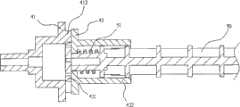
图4为本发明的局部组件侧面剖视图。Fig. 4 is a side sectional view of a partial assembly of the present invention.
图5为本发明的前进动作实施例图。Fig. 5 is a diagram of an embodiment of the forward movement of the present invention.
图6为本发明的另一前进动作实施例图。Fig. 6 is a diagram of another forward action embodiment of the present invention.
图7为本发明的转向动作实施例图。Fig. 7 is a diagram of an embodiment of the steering action of the present invention.
图8为本发明的另一转向动作实施例图。Fig. 8 is a diagram of another steering action embodiment of the present invention.
【主要组件符号说明】[Description of main component symbols]
底座10马达室11主轮口12副轮口13轴固定部14
轴槽141离合室142限位槽143马达20主轮30Shaft slot 141
轴接部31离合组件40主动件41固定轴411
离合齿412从动件42离合齿421套部422Clutch
啮合开口4221轴件50弹性件51啮合块52Engagement opening 4221
限位环突53接部54固定孔541副轮60接孔61Limiting
固定件62限位盖70Fixing
【具体实施方式】【Detailed ways】
为使贵审查员方便简洁了解本发明之创作特征、内容与优点及其所能达成之功效,现将本发明配合附图,并以实施例之表达形式分别详细说明如下:In order for your examiners to easily and concisely understand the creative features, content and advantages of the present invention and the effects it can achieve, the present invention is now described in detail in the form of embodiments in conjunction with the accompanying drawings as follows:
请配合参看图1至图3所示,本发明清洁器之移动底座于一较佳之实施例中可包含有一底座10、一马达20、一主轮30、一离合组件40、一轴件50、一副轮60及两限位盖70。Please refer to Fig. 1 to Fig. 3, the mobile base of the cleaner of the present invention may include a
前述之底座10可为一环状盘体,其上进一步设有一马达室11、一主轮口12、一副轮口13及一轴固定部14;马达室11设于底座10之一侧处,主轮口12为一贯穿设于马达室11内侧之开口,副轮口13为一设于主轮口12反向侧之开口,轴固定部14为一设于主、副轮口12和13之间的长型架体,其上凹设有一贯通轴固定部14两端之长型轴槽141,且于轴槽141靠近主轮口12端处凹设有一离合室142,并于轴槽141之槽身上横断地凹入设有一限位槽143。The
前述之马达20固定设于马达室11之中,其可驱动传动轴做正\反转之动作。The
前述之主轮30设于主轮口12之中且共转地固定于马达20之传动轴上,可受马达20之驱动而正\反向转动以带动清洁器行进,其于马达20之反向侧的中心处设有一轴接部31,其为一凹设之矩型接孔。The above-mentioned
请进一步配合参看图4所示,前述之离合组件40可旋转地对应设于离合室142中,其包含一主动件41及一从动件42;Please refer to FIG. 4 for further cooperation. The
其中主动件41之外侧端设有一固定轴411,其轴端外型对应主轮30之轴接部31并藉此配合套接于主轮30而使主动件41与主轮30呈同轴共转,主动件41内侧端之接触平面上设有复数呈环状分布之离合齿412,离合齿412之设置为一种提供两转向之装置间离合驱动功能所熟知的技术手段,故不于本文中进一步多加赘述其细节,仅就配置上做说明;Wherein the outer end of the driving part 41 is provided with a fixed shaft 411, and the shape of the shaft end corresponds to the
且其中从动件42对应配合于主动件41,其外侧端面上设有对应于主动件41之离合齿412的离合齿421,其选择性地于主轮30及主动件41正转时啮合于主动件41之离合齿412而令从动件42受主动件41之驱动正转,而于主轮30及主动件41逆转时则脱离与主动件41之离合齿412之啮合,并使从动件42脱离主动件41之驱动,且从动件42内侧端突起设有一套部422,套部422开口端处朝内凹入设有复数之长型啮合开口4221。And wherein the driven
前述之轴件50为一长杆件,其对应设于轴槽141之中,且一端对应穿设于离合组件40之从动件42的套部422内,且于套部422底壁与轴件50该端间顶靠设有一弹性件51,其可为一弹簧,用以顶推从动件42以保持其与主动件41之连接,且于轴件50该端周围壁面上突伸设有对应于啮合开口4221之啮合块52,其可滑移地穿设于啮合开口4221中并与其相互卡制,进而令轴件50与从动件42成一体共转,而轴件50之杆身上设有一限位环突53,其对应卡制于限位槽143内以提供轴件50一限位功能,再者,轴件50另端上设有一接部54,其具有非圆形断面且于端顶处设有一固定孔541例如:螺孔。The
前述之副轮60对应设于副轮口13处并与主轮30相互平行以提供清洁器一行进之功能,且其轮心处贯穿设有一接孔61,其对应啮合地套设固定于接部54上,进而使副轮60与轴件50、从动件42成同轴共转关系,而可于副轮60外侧端以一外加之固定件62例如:螺钉穿设于固定孔541以将副轮60固定于轴件50上。The aforementioned
前述之限位盖70分别对应跨设于离合组件40以及轴件50之杆身上,且固定于轴固定部14之壁面上以将离合组件40与轴件50定位。The above-mentioned limiting
请进一步配合参看图5图6所示,本发明于清洁器要朝前方前进时,可藉马达20驱动主轮30朝正向旋转,而后透过离合组件40之传动进一步地驱动轴件50及副轮60连动地前转,以使两平行之主、副轮30和60同步正转以带动清洁器之前行;Please refer to Fig. 5 and Fig. 6 for further cooperation. When the cleaner is to move forward, the
请进一步配合参看图7图8所示,于清洁器前进中碰到障碍物时,可藉马达20驱动主轮30逆向旋转,而后因离合组件40之啮合齿412和421于主轮30逆向旋转时呈现脱离啮合之状况,因此轴件50与副轮60并不受主轮30驱动而造成副轮60于原地滞留,仅主轮30独自地朝后向移动,如此一来可令清洁器以副轮60为中心进行旋转,进而可让行进方向转离障碍物,复而令主、副轮30和60同步前转以远离障碍物。Please refer to Fig. 7 and Fig. 8 for further cooperation. When the cleaner encounters an obstacle while advancing, the
而本发明-清洁器之移动底座由于仅藉由单一马达30作为驱动之动力源,因此可改善现有技术中必需要透过两个驱动马达方能解决清洁器转向之问题,对于成品之生产上而言,具有降低制作成本以及节省组装空间之优势。And the mobile base of the present invention-cleaner only uses
再者,为了另本发明于行进间能协助清洁动作更具有方向性之优势,因此本发明于另一种实施方式中,可令主轮30之外径大于副轮60,如此一来,于一般情况下本发明之行进动作为一弧形之动线,于碰撞到阻碍物时因切入角度之故,有助于主轮30之逆转而使整体转向然后倒退的动作。Furthermore, in order to assist the present invention to have a more directional advantage in the cleaning action during travel, so in another embodiment of the present invention, the outer diameter of the
综观上述,本发明在突破先前之技术结构下,确实已达到所欲增进之功效,且也非熟悉该项技艺者所易于思及,再者,本发明申请前未曾公开,其所具之进步性、实用性,显已符合创作专利之申请要件,爰依法提出创作申请,恳请贵局核准本件创作专利申请案,以励创作,至感德便。In view of the above, the present invention has indeed achieved the desired effect after breaking through the previous technical structure, and it is not easy for those who are familiar with the art to think about it. Moreover, the present invention has not been disclosed before the application, and the progress it has The nature and practicability clearly meet the application requirements for a creation patent. I submit a creation application in accordance with the law. I sincerely ask your bureau to approve this creation patent application to encourage creation. I am very grateful.
以上所述之实施例仅系为说明本发明之技术思想及特点,其目的在使熟习此项技艺之人士能够了解本发明之内容并据以实施,当不能以之限定本发明之专利范围,即大凡依本发明所揭示之精神所作之均等变化或修饰,仍应涵盖在本发明之专利范围内。The above-described embodiments are only to illustrate the technical ideas and characteristics of the present invention, and its purpose is to enable those skilled in this art to understand the content of the present invention and implement it accordingly, and should not limit the patent scope of the present invention. That is to say, all equivalent changes or modifications made according to the spirit disclosed in the present invention should still be covered by the patent scope of the present invention.
Claims (9)
Priority Applications (1)
| Application Number | Priority Date | Filing Date | Title |
|---|---|---|---|
| CN200910128317ACN101843467A (en) | 2009-03-25 | 2009-03-25 | Movable base of cleaner |
Applications Claiming Priority (1)
| Application Number | Priority Date | Filing Date | Title |
|---|---|---|---|
| CN200910128317ACN101843467A (en) | 2009-03-25 | 2009-03-25 | Movable base of cleaner |
Publications (1)
| Publication Number | Publication Date |
|---|---|
| CN101843467Atrue CN101843467A (en) | 2010-09-29 |
Family
ID=42768435
Family Applications (1)
| Application Number | Title | Priority Date | Filing Date |
|---|---|---|---|
| CN200910128317APendingCN101843467A (en) | 2009-03-25 | 2009-03-25 | Movable base of cleaner |
Country Status (1)
| Country | Link |
|---|---|
| CN (1) | CN101843467A (en) |
Cited By (5)
| Publication number | Priority date | Publication date | Assignee | Title |
|---|---|---|---|---|
| CN103860108A (en)* | 2012-12-12 | 2014-06-18 | 金宝电子工业股份有限公司 | Motion device and self-propelled cleaner with same |
| WO2019238099A1 (en)* | 2018-06-13 | 2019-12-19 | 苏州宝时得电动工具有限公司 | Automated moving device |
| CN115886667A (en)* | 2022-12-29 | 2023-04-04 | 上海高仙自动化科技发展有限公司 | A manual automatic flipping and cleaning robot |
| CN115886643A (en)* | 2021-09-30 | 2023-04-04 | 北京顺造科技有限公司 | Rotary lifting floating device and automatic cleaning equipment |
| CN117179623A (en)* | 2023-09-28 | 2023-12-08 | 珠海格力电器股份有限公司 | Cleaning body and mite removal device |
Citations (5)
| Publication number | Priority date | Publication date | Assignee | Title |
|---|---|---|---|---|
| JPH0382426A (en)* | 1989-08-25 | 1991-04-08 | Matsushita Electric Ind Co Ltd | Clutch mechanism for mobile objects with self-propelling function |
| US5504971A (en)* | 1992-06-04 | 1996-04-09 | Matsushita Appliance Corporation | Vacuum cleaner with adjustable speed power assist |
| US20040134019A1 (en)* | 2003-01-09 | 2004-07-15 | Royal Appliance Mfg. Co. | Clutchless self-propelled vacuum cleaner and nozzle height adjustment mechanism therefor |
| US20080001566A1 (en)* | 2001-06-12 | 2008-01-03 | Irobot Corporation | Method and system for multi-mode coverage for an autonomous robot |
| CN201149051Y (en)* | 2007-12-24 | 2008-11-12 | 深圳市银星智能电器有限公司 | Plastering cleaner robot advance and retreat automatic clutch drive wheel mechanism |
- 2009
- 2009-03-25CNCN200910128317Apatent/CN101843467A/enactivePending
Patent Citations (5)
| Publication number | Priority date | Publication date | Assignee | Title |
|---|---|---|---|---|
| JPH0382426A (en)* | 1989-08-25 | 1991-04-08 | Matsushita Electric Ind Co Ltd | Clutch mechanism for mobile objects with self-propelling function |
| US5504971A (en)* | 1992-06-04 | 1996-04-09 | Matsushita Appliance Corporation | Vacuum cleaner with adjustable speed power assist |
| US20080001566A1 (en)* | 2001-06-12 | 2008-01-03 | Irobot Corporation | Method and system for multi-mode coverage for an autonomous robot |
| US20040134019A1 (en)* | 2003-01-09 | 2004-07-15 | Royal Appliance Mfg. Co. | Clutchless self-propelled vacuum cleaner and nozzle height adjustment mechanism therefor |
| CN201149051Y (en)* | 2007-12-24 | 2008-11-12 | 深圳市银星智能电器有限公司 | Plastering cleaner robot advance and retreat automatic clutch drive wheel mechanism |
Cited By (7)
| Publication number | Priority date | Publication date | Assignee | Title |
|---|---|---|---|---|
| CN103860108A (en)* | 2012-12-12 | 2014-06-18 | 金宝电子工业股份有限公司 | Motion device and self-propelled cleaner with same |
| WO2019238099A1 (en)* | 2018-06-13 | 2019-12-19 | 苏州宝时得电动工具有限公司 | Automated moving device |
| CN111225556A (en)* | 2018-06-13 | 2020-06-02 | 苏州宝时得电动工具有限公司 | Self-moving equipment |
| CN115886643A (en)* | 2021-09-30 | 2023-04-04 | 北京顺造科技有限公司 | Rotary lifting floating device and automatic cleaning equipment |
| CN115886643B (en)* | 2021-09-30 | 2025-08-29 | 北京顺造科技有限公司 | Rotating lifting and floating device and automatic cleaning equipment |
| CN115886667A (en)* | 2022-12-29 | 2023-04-04 | 上海高仙自动化科技发展有限公司 | A manual automatic flipping and cleaning robot |
| CN117179623A (en)* | 2023-09-28 | 2023-12-08 | 珠海格力电器股份有限公司 | Cleaning body and mite removal device |
Similar Documents
| Publication | Publication Date | Title |
|---|---|---|
| JP6212915B2 (en) | Vehicle steering device | |
| JP6308234B2 (en) | Wheel unit | |
| CN101843467A (en) | Movable base of cleaner | |
| CN204236696U (en) | A kind of children's electric motor vehicle | |
| CN103334665A (en) | Dual-drive switcher of transmission mechanism of blind window | |
| CN102287527A (en) | Transmission shift mechanism | |
| WO2019011128A1 (en) | Articulated robot and linear actuator thereof | |
| CN103654640A (en) | Cleaning robot driving wheel mechanism | |
| CN109263464A (en) | Working in paddy field | |
| JP3150697U (en) | Directional traveling toy | |
| TWI437172B (en) | Four-wheel steering central mechanism | |
| CN105229340A (en) | Rotating machinery and robot | |
| TWI584911B (en) | Toggle switch of a shared drive assembly of a tool magazine | |
| US11598399B2 (en) | Indexed drive system | |
| JP4757930B2 (en) | Vacuum cleaner moving base | |
| CN203327503U (en) | Clutch steering device of power traveling gear | |
| CN205998051U (en) | Children's electric motor vehicle | |
| CN203106467U (en) | Child swing | |
| CN202782498U (en) | Central shaft component | |
| CN223127234U (en) | Steering clutch device of toy car | |
| TWI385090B (en) | The Construction of Multi - modal Fixed - axis Steering Wheel and Its Control Method | |
| JP5631286B2 (en) | Electric vehicle | |
| CN110606123B (en) | Steering device for non-independent suspension and vehicle with same | |
| CN204337240U (en) | A kind of massage cushion | |
| JPH0722799U (en) | Vehicle toys |
Legal Events
| Date | Code | Title | Description |
|---|---|---|---|
| C06 | Publication | ||
| PB01 | Publication | ||
| C10 | Entry into substantive examination | ||
| SE01 | Entry into force of request for substantive examination | ||
| C02 | Deemed withdrawal of patent application after publication (patent law 2001) | ||
| WD01 | Invention patent application deemed withdrawn after publication | Application publication date:20100929 |