CN101839460A - Multi-layer coaming heat radiator - Google Patents
Multi-layer coaming heat radiatorDownload PDFInfo
- Publication number
- CN101839460A CN101839460ACN200910249524ACN200910249524ACN101839460ACN 101839460 ACN101839460 ACN 101839460ACN 200910249524 ACN200910249524 ACN 200910249524ACN 200910249524 ACN200910249524 ACN 200910249524ACN 101839460 ACN101839460 ACN 101839460A
- Authority
- CN
- China
- Prior art keywords
- layer
- skirting
- heat radiator
- heat dissipation
- heat
- Prior art date
- Legal status (The legal status is an assumption and is not a legal conclusion. Google has not performed a legal analysis and makes no representation as to the accuracy of the status listed.)
- Granted
Links
Images


Landscapes
- Arrangement Of Elements, Cooling, Sealing, Or The Like Of Lighting Devices (AREA)
Abstract
Translated fromChineseDescription
Translated fromChinese技术领域technical field
本发明有关于一种散热装置,特别是指一种将发光件与天花板上轻钢架的多层式围板相结合,从而具有极佳散热效果的发光源散热装置。The invention relates to a heat dissipation device, in particular to a heat dissipation device for a light emitting source which combines a light-emitting element with a multi-layer hoarding of a light steel frame on the ceiling, thereby having an excellent heat dissipation effect.
背景技术Background technique
按,在照明设备上由于能源危机的压力,使得传统白炽灯等照明设备必然会面临市场上的销售量萎缩的趋势;同时,又由于对环保意识的重视,使得日光灯管汞污染的问题,也更显突出。Press, due to the pressure of the energy crisis on lighting equipment, the sales volume of traditional incandescent lamps and other lighting equipment will inevitably face the trend of shrinking in the market; at the same time, due to the emphasis on environmental protection awareness, the problem of mercury pollution in fluorescent tubes is also more prominent.
近年来,由于绿色光电产品成为热门产业,因此效率高、省电能、寿命长、冷发光、反应速度快及色彩一致性高等众多较传统发光件更佳的优点,使得发光二极管(LED)的发展占有举足轻重的角色,因此发光二极管用于照明设备是现今光电产业、照明产业发展的重点,且逐渐地取代传统白炽灯的应用。所以与发光二极管的寿命、功率攸关的其散热效率的高低,是现行发光二极管在发展应用上的关键性问题;而现有技术为解决发光二极管的散热问题,主要是将发光二极管结合于一散热基座上使用,该散热基座进一步设有数个散热鳍片,借助该散热鳍片达到导引排出热量的散热效果。如此,该现有发光二极管散热技术虽具有某程度的散热效果,但由于必须配合现有灯泡(如MR16或其他规格的白炽灯)的外观及尺寸问题,所以散热无法有效率地解决,同时也无法有效提高工作功率。In recent years, as green optoelectronic products have become a popular industry, many advantages over traditional light-emitting devices, such as high efficiency, energy saving, long life, cold light emission, fast response speed and high color consistency, make the development of light-emitting diodes (LEDs) Occupying a pivotal role, the use of light-emitting diodes in lighting equipment is the focus of the development of the optoelectronic industry and lighting industry today, and gradually replaces the application of traditional incandescent lamps. Therefore, the heat dissipation efficiency, which is closely related to the life and power of light-emitting diodes, is a key issue in the development and application of current light-emitting diodes; and in order to solve the heat dissipation problem of light-emitting diodes in the prior art, it is mainly to combine light-emitting diodes into one It is used on the heat dissipation base, and the heat dissipation base is further provided with several heat dissipation fins, and the heat dissipation effect of guiding and discharging heat can be achieved by means of the heat dissipation fins. In this way, although the existing heat dissipation technology for light-emitting diodes has a certain degree of heat dissipation effect, due to the appearance and size problems of existing light bulbs (such as MR16 or incandescent lamps of other specifications), the heat dissipation cannot be efficiently solved, and at the same time It is impossible to effectively increase the working power.
因此,如何改善此类发光件散热装置应用上的不足问题,成为业界应努力解决、克服的下一个重要方向。Therefore, how to improve the shortcomings in the application of such light-emitting device heat sinks has become the next important direction that the industry should strive to solve and overcome.
因此,本发明有鉴于现有发光件散热装置应用上的缺点及其装置设计上未臻理想的事实,公布了一种更具散热效果及经济实用性的多层式围板散热装置,以服务社会大众及促进此业的发展。Therefore, in view of the shortcomings in the application of the existing light-emitting heat dissipation device and the fact that the design of the device is not ideal, the present invention discloses a multi-layer coaming heat dissipation device with more heat dissipation effect and economical practicability to serve The general public and promote the development of this industry.
发明内容Contents of the invention
本发明的目的在于提供一种多层式围板散热装置,其能使发光件(尤指发光二极管)的热量能借助室内天花板上现有空间或气流通道加以迅速排导,达到极佳的散热效果,进而能积极确保发光件使用上的功能及寿命。The purpose of the present invention is to provide a multi-layer coaming heat dissipation device, which can make the heat of the light-emitting parts (especially light-emitting diodes) be quickly discharged by means of the existing space or air flow channel on the indoor ceiling, so as to achieve excellent heat dissipation Effect, and then can actively ensure the function and life of the luminous parts in use.
本发明的再一目的在于提供一种多层式围板散热装置,其能结合空调设备的多层式出、入风口架加以设置,使具有极佳的散热操作经济性,并积极达到能便利发光件应用于室内照明的普遍推广作用。Another object of the present invention is to provide a multi-layer coaming heat dissipation device, which can be installed in combination with multi-layer air outlet and air inlet frames of air-conditioning equipment, so that it has excellent heat dissipation operation economy, and actively achieves energy efficiency. The general promotion effect of luminous parts applied to indoor lighting.
本发明的又一目的在于提供一种多层式围板散热装置,其能借助多层式围板的反射,达到提升其亮度及光线均匀度,进而具有较佳的照明效果。Yet another object of the present invention is to provide a multi-layer shroud cooling device, which can improve its brightness and light uniformity by means of the reflection of the multi-layer shroud, thereby having a better lighting effect.
本发明为达到上述目的所采用的技术手段包括:一散热基座模块;一导热柱,其一端连接于所述散热基座模块,另一端设有一端头部;至少一发光件,设于所述导热柱的端头部;一多层式围板,其设有一通孔,用以供所述导热柱的穿设,所述多层式围板设于天花板上,或应用于现有天花板上的空调的出、入风口架。The technical means adopted by the present invention to achieve the above purpose include: a heat dissipation base module; a heat conduction column, one end of which is connected to the heat dissipation base module, and the other end is provided with an end head; at least one light-emitting element is arranged on the The end of the heat conduction column; a multi-layer hoarding, which is provided with a through hole for the penetration of the heat conduction column, and the multi-layer hoarding is set on the ceiling, or applied to the existing ceiling The air outlet and air inlet rack of the air conditioner on the top.
本发明的有益效果在于:其能使发光件的热量借助室内天花板上现有空间或气流通道加以迅速排导,达到极佳的散热效果,进而能积极确保发光件使用上的功能及寿命;还可以结合空调设备的多层式出、入风口架加以设置,使其具有极佳的散热操作经济性,并积极达到能便利发光件应用于室内照明的普遍推广作用以及借助多层式围板的反射,达到提升其亮度及光线均匀度,进而具有较佳的照明效果。The beneficial effect of the present invention is that: it can quickly conduct the heat of the luminous element by means of the existing space or airflow channel on the indoor ceiling, so as to achieve an excellent heat dissipation effect, and then actively ensure the function and life of the luminous element; It can be set in combination with the multi-layer air outlet and air inlet frame of the air-conditioning equipment, so that it has excellent heat dissipation operation economy, and actively achieves the general promotion effect of facilitating the application of luminous parts to indoor lighting and the use of multi-layer hoardings Reflection, to improve its brightness and light uniformity, and then have a better lighting effect.
为使本发明的技术、特征及所达成的功效能被进一步的了解与认识,以下就较佳的实施例及配合附图详细的说明,说明如后:In order to further understand and understand the technology, features and achieved effects of the present invention, the following is a detailed description of the preferred embodiments and accompanying drawings, as follows:
附图说明Description of drawings
图1是本发明的立体示意图。Fig. 1 is a schematic perspective view of the present invention.
图2是本发明的分解示意图。Fig. 2 is an exploded schematic view of the present invention.
图2A是本发明数个发光二极管的实施示意图。FIG. 2A is a schematic diagram of the implementation of several LEDs of the present invention.
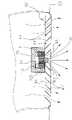
图3是本发明的剖视示意图。Fig. 3 is a schematic cross-sectional view of the present invention.
图4是本发明的应用状态示意图。Fig. 4 is a schematic diagram of the application state of the present invention.
图号对照说明:Description of drawing number comparison:
10 散热基座模块 11 基座 12 侧散热通口 121 散热鳍片10
13 端散热通口 14 风扇 15 过滤件 20 导热柱13
21 端头部 30 发光件 40 多层式围板 41 基板部21
411、421 斜面部 42 环板 43 通孔44风道间隙50 天花板411, 421 Inclined
具体实施方式Detailed ways
请参阅图1、2及3,本发明多层式围板散热装置,其包括有一散热基座模块10、导热柱20、发光件30及多层式围板40;Please refer to Figures 1, 2 and 3, the multi-layer coaming heat dissipation device of the present invention includes a heat
其中,所述散热基座模块10包括有一基座11,所述基座11为金属、陶瓷材料、塑胶材料或高导热性复合材料所制成;在本较佳实施方式中,所述基座11为一散热座,其设有至少一侧散热通口12及端散热通口13(包括上、下端),所述等侧散热通12、端散热通口13间设有数个散热鳍片121,再者,所述基座11上方或侧边进一步设有一风扇14,所述风扇14对应于所述侧散热通12或所述端散热通13,以借助风扇的转动带动外部空气加速热量的排导;另,所述散热基座模块10上设有相关电路板及电子元件(图中未示)。Wherein, the heat
在其它实施方式中,所述基座11可结合一过滤件15,即以所述过滤件15套设于所述风扇14及基座11外侧,所述过滤件15可为如滤网、滤棉等可过滤空气中灰尘的材质。In other embodiments, the
其中,所述导热柱20一端连接于所述散热基座模块10(于本实施例为连接于基座11),所述导热柱20可为金属、陶瓷材料、热导管或高导热性复合材料所制成,所述导热柱20的另一端设有一端头部21;Wherein, one end of the
其中,所述发光件30设于所述导热柱20的端头部21,所述发光件30于本实施例为一发光二极管,所述发光件30电性连接所述散热基座模块10的相关电路板及电子元件;又如图2A所示,所述发光件30也可由数个发光二极管所组成。Wherein, the light-emitting
其中,所述多层式围板40包括有一中央部位的基板部41及连接环设于所述基板部41周边的数个环板42,所述基板部41设有一通孔43,且所述基板部41与环板42间,以及数个环板42本身间可具有风道间隙44,又如图3所示,所述基板部41及环板42分别具有斜面部411、421,所述斜面部411、421可进一步涂布有一反射层(图中未示),用以达到较佳的光线反射效果,又,所述多层式围板40可为一金属材料所制成,使具有散热的功能。Wherein, the
前述所述多层式围板40可装置于天花板轻钢架隔间,或直接应用现有天花板上空调的多层式出、入风口架,以达到整体应用上的经济效益性;本发明多层式围板散热装置组合时,将连接于散热基座模块10(基座11)底部的导热柱20穿过所述多层式围板40(基板部41)的通孔43,使所述端头部21凸出于所述基板部41外(或下方),使所述发光件30得以进行照明,而所述多层式围板40则固设于天花板50上的空调气流通道处(如图4所示)。The aforementioned
请一并参阅图4,本发明多层式围板散热装置应用时,所述发光件30所产生的热量将借助所述导热柱20导引至所述多层式围板40及基座11,而由于所述多层式围板40及基座11可设于所述天花板50上的所述空调多层式出、入风口架处,因此可利用天花板上现有空间,当空调工作时,可利用送风或吸风的气流将所述发光件30所产生的热量通过所述风道间隙44及时、迅速地排出,而达到极佳的散热效果,且由于本发明是利用既有的空调气流进行散热,故不需额外的动力耗费,具有相当散热操作的经济效益性。而倘若未启动空调时,也可以借助所述多层式围板40及基座11进行散热,或进一步启动所述风扇14进行散热。当然,若于空调作用时且同时配合所述风扇14进行散热,则将达到最佳的散热效果,更能积极延长与确保发光件使用上的功能及寿命。Please also refer to FIG. 4 , when the multi-layer shroud cooling device of the present invention is applied, the heat generated by the light-emitting
再者,由于所述多层式围板40的斜面部411、421涂布有一反射层,能借助所述多层式围板40反射层的反射,达到提升其整体的亮度及光线均匀度,达到较佳的照明效果。另,本发明由于可利用现有空调气流通道及结合现有多层式围板设备,具有极佳的散热操作经济性,并积极达到能便利推广于室内照明的普遍应用的作用。Furthermore, since the
综上所述,虽本发明以较佳实施例揭露以上内容,但并非用以限定本发明实施的范围,任何本领域技术人员,在不脱离本发明的精神和范围内,当可作些许的改动与润饰,即凡依本发明所做的均等变化与修饰,应为本发明专利范围所涵盖。In summary, although the present invention discloses the above content with preferred embodiments, it is not intended to limit the scope of the present invention. Any person skilled in the art may make some modifications without departing from the spirit and scope of the present invention. Changes and modifications, that is, all equivalent changes and modifications made according to the present invention, should be covered by the patent scope of the present invention.
Claims (10)
Priority Applications (1)
| Application Number | Priority Date | Filing Date | Title |
|---|---|---|---|
| CN2009102495243ACN101839460B (en) | 2009-03-17 | 2009-12-23 | Multi-layer enclosure cooling device |
Applications Claiming Priority (3)
| Application Number | Priority Date | Filing Date | Title |
|---|---|---|---|
| CN200920006986.8 | 2009-03-17 | ||
| CN200920006986 | 2009-03-17 | ||
| CN2009102495243ACN101839460B (en) | 2009-03-17 | 2009-12-23 | Multi-layer enclosure cooling device |
Publications (2)
| Publication Number | Publication Date |
|---|---|
| CN101839460Atrue CN101839460A (en) | 2010-09-22 |
| CN101839460B CN101839460B (en) | 2013-02-20 |
Family
ID=42743015
Family Applications (1)
| Application Number | Title | Priority Date | Filing Date |
|---|---|---|---|
| CN2009102495243AExpired - Fee RelatedCN101839460B (en) | 2009-03-17 | 2009-12-23 | Multi-layer enclosure cooling device |
Country Status (1)
| Country | Link |
|---|---|
| CN (1) | CN101839460B (en) |
Cited By (3)
| Publication number | Priority date | Publication date | Assignee | Title |
|---|---|---|---|---|
| CN106322706A (en)* | 2016-08-26 | 2017-01-11 | 沈炜 | Integrated air conditioner air outlet LED lamp |
| CN106895379A (en)* | 2017-04-28 | 2017-06-27 | 东莞市闻誉实业有限公司 | Socket joint type lighting assembly |
| CN106979554A (en)* | 2016-01-15 | 2017-07-25 | 三星电子株式会社 | Air-conditioning |
Citations (9)
| Publication number | Priority date | Publication date | Assignee | Title |
|---|---|---|---|---|
| DE8703913U1 (en)* | 1987-03-16 | 1987-04-23 | Gebrüder Trox, GmbH, 4133 Neukirchen-Vluyn | Air passage for air conditioning or ventilation systems |
| US5664872A (en)* | 1993-11-23 | 1997-09-09 | Smiths Industries Plc | Combined lamp and fan assembly |
| US20050276053A1 (en)* | 2003-12-11 | 2005-12-15 | Color Kinetics, Incorporated | Thermal management methods and apparatus for lighting devices |
| JP2006100052A (en)* | 2004-09-29 | 2006-04-13 | Moriyama Sangyo Kk | Light emitting device |
| CN2898695Y (en)* | 2006-05-10 | 2007-05-09 | 池建能 | Composite ceiling tuyere with illuminator |
| CN201193790Y (en)* | 2008-05-09 | 2009-02-11 | 范金晶 | LED bulb for replacing cup-shaped reflecting halogen bulb |
| CN201196359Y (en)* | 2008-03-20 | 2009-02-18 | 深圳市俄菲照明有限公司 | High power LED barrel lamp with anti-dazzle function |
| EP2025999A2 (en)* | 2007-08-13 | 2009-02-18 | S.G.F. Associates, Inc. | Power LED lighting assembly having a forced air cooling device comprising a heat sink and a fan |
| US7878692B2 (en)* | 2007-11-13 | 2011-02-01 | Inteltech Corporation | Light fixture assembly having improved heat dissipation capabilities |
- 2009
- 2009-12-23CNCN2009102495243Apatent/CN101839460B/ennot_activeExpired - Fee Related
Patent Citations (9)
| Publication number | Priority date | Publication date | Assignee | Title |
|---|---|---|---|---|
| DE8703913U1 (en)* | 1987-03-16 | 1987-04-23 | Gebrüder Trox, GmbH, 4133 Neukirchen-Vluyn | Air passage for air conditioning or ventilation systems |
| US5664872A (en)* | 1993-11-23 | 1997-09-09 | Smiths Industries Plc | Combined lamp and fan assembly |
| US20050276053A1 (en)* | 2003-12-11 | 2005-12-15 | Color Kinetics, Incorporated | Thermal management methods and apparatus for lighting devices |
| JP2006100052A (en)* | 2004-09-29 | 2006-04-13 | Moriyama Sangyo Kk | Light emitting device |
| CN2898695Y (en)* | 2006-05-10 | 2007-05-09 | 池建能 | Composite ceiling tuyere with illuminator |
| EP2025999A2 (en)* | 2007-08-13 | 2009-02-18 | S.G.F. Associates, Inc. | Power LED lighting assembly having a forced air cooling device comprising a heat sink and a fan |
| US7878692B2 (en)* | 2007-11-13 | 2011-02-01 | Inteltech Corporation | Light fixture assembly having improved heat dissipation capabilities |
| CN201196359Y (en)* | 2008-03-20 | 2009-02-18 | 深圳市俄菲照明有限公司 | High power LED barrel lamp with anti-dazzle function |
| CN201193790Y (en)* | 2008-05-09 | 2009-02-11 | 范金晶 | LED bulb for replacing cup-shaped reflecting halogen bulb |
Cited By (6)
| Publication number | Priority date | Publication date | Assignee | Title |
|---|---|---|---|---|
| CN106979554A (en)* | 2016-01-15 | 2017-07-25 | 三星电子株式会社 | Air-conditioning |
| CN106979554B (en)* | 2016-01-15 | 2023-04-18 | 三星电子株式会社 | Air conditioner |
| CN106322706A (en)* | 2016-08-26 | 2017-01-11 | 沈炜 | Integrated air conditioner air outlet LED lamp |
| CN106322706B (en)* | 2016-08-26 | 2019-04-23 | 南京灵雀智能制造有限公司 | Integrated air conditioner air outlet LED light |
| CN106895379A (en)* | 2017-04-28 | 2017-06-27 | 东莞市闻誉实业有限公司 | Socket joint type lighting assembly |
| CN106895379B (en)* | 2017-04-28 | 2019-08-06 | 东莞市闻誉实业有限公司 | Socket joint type lighting assembly |
Also Published As
| Publication number | Publication date |
|---|---|
| CN101839460B (en) | 2013-02-20 |
Similar Documents
| Publication | Publication Date | Title |
|---|---|---|
| CN201615371U (en) | LED lighting device and LED module that are easy to dissipate heat | |
| US8393764B2 (en) | Multilayered surrounding plate type heat dissipating structure | |
| CN201983042U (en) | Light-emitting diode (LED) lamp | |
| CN201673359U (en) | Projector | |
| CN101329016B (en) | Semiconductor lighting fixture having high-efficiency heat radiation structure and manufacture method thereof | |
| JP6377432B2 (en) | LED floodlight | |
| CN100379038C (en) | Water-cooled LED heat sink | |
| CN101839460A (en) | Multi-layer coaming heat radiator | |
| CN201162983Y (en) | High-efficiency cooling type automobile front shining lamp | |
| CN201032082Y (en) | Light emitting diode module | |
| CN101349418A (en) | Radiating module of light-emitting element | |
| CN201412808Y (en) | Heat radiation structure of LED lamp | |
| CN101761807A (en) | LED illuminator and LED modules | |
| CN201421057Y (en) | Radiating module of lamp | |
| TWM313260U (en) | Light source device for projector | |
| TWM305302U (en) | Large-sized LED lamp combination structure | |
| CN201159444Y (en) | Multi-layer radiating fin for LED lamp | |
| CN204593308U (en) | A kind of super-high-power LED stage lighting | |
| CN100504159C (en) | Integrated heat dissipation LED street light | |
| CN2909004Y (en) | The structure of LED passive heat dissipation | |
| TWM319522U (en) | Heat-sink light-emitting diode module and power supply device for the same | |
| TWM322561U (en) | Backlight module | |
| CN201041334Y (en) | Heat radiator for high power LED lamp | |
| CN201306693Y (en) | Heat dissipation device with turbine exhaust fan and LED lamp comprising heat dissipation device | |
| CN210835561U (en) | Projection lighting integrated device |
Legal Events
| Date | Code | Title | Description |
|---|---|---|---|
| C06 | Publication | ||
| PB01 | Publication | ||
| C10 | Entry into substantive examination | ||
| SE01 | Entry into force of request for substantive examination | ||
| C14 | Grant of patent or utility model | ||
| GR01 | Patent grant | ||
| CF01 | Termination of patent right due to non-payment of annual fee | Granted publication date:20130220 Termination date:20141223 | |
| EXPY | Termination of patent right or utility model |