CN101829993A - Rack crank slide block type parallel coupling under-driving robot finger device - Google Patents
Rack crank slide block type parallel coupling under-driving robot finger deviceDownload PDFInfo
- Publication number
- CN101829993A CN101829993ACN 201010164892CN201010164892ACN101829993ACN 101829993 ACN101829993 ACN 101829993ACN 201010164892CN201010164892CN 201010164892CN 201010164892 ACN201010164892 ACN 201010164892ACN 101829993 ACN101829993 ACN 101829993A
- Authority
- CN
- China
- Prior art keywords
- slide block
- section
- joint shaft
- finger
- gear
- Prior art date
- Legal status (The legal status is an assumption and is not a legal conclusion. Google has not performed a legal analysis and makes no representation as to the accuracy of the status listed.)
- Granted
Links
Images


Landscapes
- Manipulator (AREA)
Abstract
Translated fromChinese
Description
Translated fromChinese技术领域technical field
本发明属于拟人机器人手技术领域,特别涉及一种柔性件曲柄滑块式并联耦合欠驱动机器人手指装置的结构设计。The invention belongs to the technical field of anthropomorphic robot hands, in particular to a structural design of a flexible part crank slider type parallel coupling underactuated robot finger device.
背景技术Background technique
机器人手是机器人不可或缺的一部分,相对于机器人的其它部分,机器人手具有关节自由度多、体积小,非常灵巧、控制复杂等特点与难点。机器人手主要用于对物体的抓持和空间移动以及做手势等其它手部动作。目前现有的灵巧手虽然控制灵活,但是电机数量多,结构非常复杂,控制难度相当大,制造和维护成本非常高,这些因素阻碍了灵巧手型机器人手在现实生活中的推广应用。近年来快速发展的耦合抓取型机器人手和欠驱动抓取型机器人手虽然不具备灵巧手的高灵活度,但是电机数量少,结构简单,控制容易,大大降低了制造和使用成本,并且能较好抓取常见物体,成为发展和研究的热点。The robot hand is an indispensable part of the robot. Compared with other parts of the robot, the robot hand has many joint freedoms, small size, very dexterous, complex control and other characteristics and difficulties. The robot hand is mainly used for grasping objects, moving in space, and making gestures and other hand movements. Although the existing dexterous hands are flexible in control, they have a large number of motors, a very complex structure, considerable difficulty in control, and very high manufacturing and maintenance costs. These factors hinder the popularization and application of dexterous hand-shaped robot hands in real life. Although the coupled grasping robot hand and the underactuated grasping robot hand developed rapidly in recent years do not have the high flexibility of the dexterous hand, they have a small number of motors, a simple structure, and easy control, which greatly reduces the cost of manufacturing and use, and can Better grasping of common objects has become a hotspot of development and research.
已有的一种双关节并联欠驱动机器人手指装置,如中国发明专利CN 101633171A,包括基座、电机、近关节轴、远关节轴和末端指段,还包括分别实现耦合和欠驱动转动的传动机构以及多个簧件解耦装置等。当手指碰触物体前实现多关节耦合转动的效果,当手指碰触物体后采用多关节欠驱动方式抓取物体。该装置的不足之处为:该装置由于采用了两套传动机构分别实现耦合和欠驱动抓取,使得整个手指结构复杂,制造加工成本高;该装置耦合传动机构和欠驱动传动机构相互影响,虽然采用了三个簧件来解耦,但内耗了电机的功率;该装置的两套传动机构平行排列,再加上多个簧件在关节轴上安装,致使手指过于粗大,增加了制造、安装和维护的成本和难度。An existing double-joint parallel underactuated robot finger device, such as the Chinese invention patent CN 101633171A, includes a base, a motor, a proximal joint shaft, a distal joint shaft, and a terminal finger segment, and also includes a transmission that realizes coupling and underactuated rotation respectively. mechanism and multiple spring decoupling devices, etc. When the finger touches the object, the effect of multi-joint coupling rotation is realized, and when the finger touches the object, the multi-joint underactuation method is used to grasp the object. The disadvantages of this device are: the device adopts two sets of transmission mechanisms to achieve coupling and under-actuated grasping respectively, which makes the structure of the whole finger complex and the cost of manufacturing and processing is high; the coupling transmission mechanism and the under-actuation transmission mechanism of the device affect each other, Although three springs are used for decoupling, the power of the motor is consumed internally; the two sets of transmission mechanisms of the device are arranged in parallel, and multiple springs are installed on the joint shaft, resulting in too thick fingers, which increases manufacturing, Cost and difficulty of installation and maintenance.
发明内容Contents of the invention
本发明的目的是为了克服已有技术的不足之处,提供一种齿条曲柄滑块式并联耦合欠驱动机器人手指装置,该装置能实现耦合转动与欠驱动转动相结合的效果,能耦合拟人化抓取,且具备欠驱动自适应功能,结构紧凑,制造、维护成本低,外形与人手指相似,适用于拟人机器人手。The purpose of the present invention is to overcome the deficiencies of the prior art, and provide a rack-crank slider-type parallel coupling underactuated robot finger device, which can realize the combined effect of coupling rotation and underactuated rotation, and can couple anthropomorphic It has the function of self-adaptive under-actuation, compact structure, low manufacturing and maintenance costs, similar shape to human fingers, and is suitable for anthropomorphic robot hands.
本发明采用如下技术方案:The present invention adopts following technical scheme:
本发明所述的一种齿条曲柄滑块式并联耦合欠驱动机器人手指装置,包括基座、近关节轴、第一指段、远关节轴、第二指段和电机,所述的电机设置在基座中,电机的输出轴与近关节轴相连;所述的近关节轴套设在所述的基座中,所述的远关节轴套设在第一指段中,所述的第二指段套固在所述的远关节轴上;其特征在于:该齿条曲柄滑块式并联耦合欠驱动机器人手指装置还包括齿轮、传动轮、第一滑块、齿条、第二滑块、连杆、第一簧件和第二簧件;所述的第一指段套固在近关节轴上;所述的齿轮套设在近关节轴上,并与基座固接;所述的传动轮套固在远关节轴上,并与第二指段固接;所述的连杆一端与第二滑块铰接,另一端与传动轮铰接;所述的齿条与第一滑块固接,并与齿轮啮合;在所述的第一指段中设有相互平行的第一滑槽和第二滑槽,所述的第一滑块镶嵌在第一滑槽中,抓取物体时沿第一滑槽方向滑动;第二滑块镶嵌在第二滑槽中,抓取物体时沿第二滑槽方向滑动;所述的第一滑块与第二滑块活接触;所述的第一簧件设置在第一指段中,第一簧件的一端与第一指段相连,另一端与第一滑块相连;所述的第二簧件设置在第一指段中,第二簧件的两端分别与第一指段和第二滑块相连。A rack crank slider type parallel coupling underactuated robot finger device according to the present invention comprises a base, a proximal joint shaft, a first finger segment, a distal joint shaft, a second finger segment and a motor, and the motor is set In the base, the output shaft of the motor is connected to the proximal joint shaft; the proximal joint shaft is sleeved in the base, the distal joint shaft is sleeved in the first finger segment, and the second joint shaft is sleeved in the first finger section. The two finger segments are fixed on the distal joint shaft; it is characterized in that: the rack crank slider type parallel coupling underactuated robot finger device also includes a gear, a transmission wheel, a first slider, a rack, a second slider block, connecting rod, first spring and second spring; the first finger segment is sleeved on the shaft near the joint; the gear is sleeved on the shaft near the joint and fixed to the base; the The transmission wheel sleeve is fixed on the distal joint shaft and is fixedly connected with the second finger section; one end of the connecting rod is hinged with the second slider, and the other end is hinged with the transmission wheel; the rack is connected with the first slider The block is fixed and meshed with the gear; a first chute and a second chute parallel to each other are provided in the first finger segment, and the first slider is embedded in the first chute, grabbing The object slides along the direction of the first chute; the second slider is embedded in the second chute, and slides along the direction of the second chute when grabbing the object; the first slider is in live contact with the second slider; The first spring part is arranged in the first finger section, one end of the first spring part is connected with the first finger section, and the other end is connected with the first slider; the second spring part is arranged in the first finger section , the two ends of the second spring member are respectively connected with the first finger section and the second sliding block.
本发明所述的一种齿条曲柄滑块式并联耦合欠驱动机器人手指装置,包括基座、近关节轴、第一指段、远关节轴、第二指段和电机,所述的电机设置在基座中,电机的输出轴与近关节轴相连;所述的近关节轴套设在所述的基座中,所述的远关节轴套设在第一指段中,所述的第二指段套固在所述的远关节轴上;其特征在于:该齿条曲柄滑块式并联耦合欠驱动机器人手指装置还包括齿轮、传动轮、第一滑块、第二滑块、第一簧件、第二簧件、第三簧件、齿条和连杆;所述的第一指段套接在近关节轴上;所述的第三簧件套在近关节轴上,两端分别连接第一指段和近关节轴;所述的齿轮套设在近关节轴上,齿轮与基座固接;所述的传动轮套固在远关节轴上,传动轮与第二指段固接;所述的连杆一端与传动轮铰接,另一端与第二滑块铰接;所述的齿条与第一滑块固接,并与第一齿轮啮合;在所述的第一指段中设有相互平行的第一滑槽和第二滑槽,所述的第一滑块镶嵌在第一指段的第一滑槽中,抓取物体时沿平行于第一滑槽的方向滑动;所述的第二滑块镶嵌在第一指段的第二滑槽中,抓取物体时沿平行于第二滑槽的方向滑动;第一滑块与第二滑块活接触;所述的第一簧件设置在第一指段中,第一簧件的一端与第一指段相连,另一端与第一滑块相连;所述的第二簧件设置在第一指段中,第二簧件的两端分别与第一指段和第二滑块相连。A rack crank slider type parallel coupling underactuated robot finger device according to the present invention comprises a base, a proximal joint shaft, a first finger segment, a distal joint shaft, a second finger segment and a motor, and the motor is set In the base, the output shaft of the motor is connected to the proximal joint shaft; the proximal joint shaft is sleeved in the base, the distal joint shaft is sleeved in the first finger segment, and the second joint shaft is sleeved in the first finger section. The two finger segments are sleeved and fixed on the distal joint shaft; it is characterized in that: the rack crank slider type parallel coupling underactuated robot finger device also includes a gear, a transmission wheel, a first slider, a second slider, and a second slider. A spring, a second spring, a third spring, a rack and a connecting rod; the first finger segment is sleeved on the shaft near the joint; the third spring is sleeved on the shaft near the joint, and the two The ends are respectively connected to the first finger segment and the shaft near the joint; the gear is sleeved on the shaft near the joint, and the gear is fixedly connected to the base; the transmission wheel is sleeved on the shaft far away, and the transmission wheel is connected to the second finger One end of the connecting rod is hinged to the transmission wheel, and the other end is hinged to the second slider; the rack is fixed to the first slider and meshed with the first gear; There are a first chute and a second chute parallel to each other in the finger section, the first slider is embedded in the first chute of the first finger section, and when grabbing an object, it is parallel to the first chute. direction sliding; the second slider is embedded in the second chute of the first finger segment, and slides in a direction parallel to the second chute when grabbing an object; the first slider is in live contact with the second slider; The first spring part is arranged in the first finger section, one end of the first spring part is connected with the first finger section, and the other end is connected with the first slider; the second spring part is arranged in the first finger section Among them, the two ends of the second spring member are respectively connected with the first finger section and the second sliding block.
本发明所述的齿条曲柄滑块式并联耦合欠驱动机器人手指装置,其特征在于:所述的第一滑块与第二滑块的活接触方式采用单面接触,所述的第一滑块推动第二滑块向手指内滑移。The rack crank slider type parallel coupling underactuated robot finger device according to the present invention is characterized in that: the living contact mode between the first slider and the second slider adopts single-sided contact, and the first slider block to push the second slider to slide inwardly of the finger.
本发明所述的齿条曲柄滑块式并联耦合欠驱动机器人手指装置,其特征在于:所述的第一滑块与第二滑块的活接触方式采用绳连接,所述的第一滑块拉动第二滑块向手指内滑移。The rack crank slider type parallel coupling underactuated robot finger device according to the present invention is characterized in that: the live contact between the first slider and the second slider is connected by a rope, and the first slider Pull the second slider to slide your finger inward.
本发明所述的齿条曲柄滑块式并联耦合欠驱动机器人手指装置,其特征在于:所述的第一簧件和第二簧件采用拉簧、压簧或弹性绳,所述的第三簧件采用扭簧、拉簧或压簧。The rack crank slider type parallel coupling underactuated robot finger device according to the present invention is characterized in that: the first spring member and the second spring member adopt extension springs, compression springs or elastic ropes, and the third The spring part adopts torsion spring, extension spring or compression spring.
本发明所述的齿条曲柄滑块式并联耦合欠驱动机器人手指装置,其特征在于:还包括传动机构,所述的传动机构包括减速器、第一齿轮和第二齿轮;所述的电机的输出轴与减速器的输入轴相连,所述的第一齿轮套固在减速器的输出轴上,所述的第二齿轮套固在近关节轴上,所述的第一齿轮与第二齿轮啮合。The rack crank slider type parallel coupling underactuated robot finger device according to the present invention is characterized in that: it also includes a transmission mechanism, and the transmission mechanism includes a reducer, a first gear and a second gear; The output shaft is connected to the input shaft of the reducer, the first gear is fixed on the output shaft of the reducer, the second gear is fixed on the proximal joint shaft, the first gear and the second gear engage.
本发明所述的齿条曲柄滑块式并联耦合欠驱动机器人手指装置,其特征在于:所述的第二滑块表面覆盖有滑块表面板。The rack crank slider type parallel coupling underactuated robot finger device according to the present invention is characterized in that the surface of the second slider is covered with a slider surface plate.
本发明所述的齿条曲柄滑块式并联耦合欠驱动机器人手指装置,其特征在于:所述的近关节轴与基座之间设置有轴承,所述的近关节轴与齿轮之间设置有轴承。The rack crank slider type parallel coupling underactuated robot finger device according to the present invention is characterized in that: a bearing is arranged between the joint-proximal shaft and the base, and a bearing is provided between the joint-proximal shaft and the gear. bearings.
本发明与现有技术相比,具有以下优点和突出性效果:Compared with the prior art, the present invention has the following advantages and outstanding effects:
本发明装置利用齿轮、齿条、连杆、双滑块和簧件综合实现了耦合转动与欠驱动转动紧密结合的传动效果,不仅能够耦合转动更拟人化地抓取物体,而且具备欠驱动功能,自适应抓取不同形状、大小的物体;该装置结构简洁紧凑,安装容易,制造加工成本低;该装置实现了耦合传动机构和欠驱动传动机构有机融合,不相互影响,利用滑块活接触的多种方式实现了自然解耦,此解耦不消耗电机功率,能量利用率高。其中第二指段的曲柄滑块机构能够通过主动滑块运动很短的距离实现第二指段大角度的转动。外形与人手手指相似,可以作为拟人机器人手的一个手指或手指的一部分,也可以用多个这样的基于齿条和曲柄滑块的并联耦合欠驱动手指组合成为机器人手,用以达到拟人机器人手高关节自由度、高自适应性的优良效果。The device of the present invention utilizes gears, racks, connecting rods, double sliders and springs to comprehensively realize the transmission effect of the close combination of coupling rotation and under-actuated rotation, and can not only grab objects in a more anthropomorphic way through coupled rotation, but also has an under-actuated function , self-adaptively grabbing objects of different shapes and sizes; the device has a simple and compact structure, easy installation, and low manufacturing and processing costs; the device realizes the organic integration of the coupling transmission mechanism and the underactuated transmission mechanism without mutual influence, and uses the slider to make contact Natural decoupling is realized in a variety of ways. This decoupling does not consume motor power and has high energy utilization. Wherein the slider crank mechanism of the second finger section can realize the large-angle rotation of the second finger section through the active slider moving a very short distance. The shape is similar to that of a human finger. It can be used as a finger or a part of an anthropomorphic robot hand. It can also be combined into a robot hand with multiple such parallel coupled underactuated fingers based on racks and crank sliders to achieve anthropomorphic robot hands. Excellent effect of high joint freedom and high adaptability.
附图说明Description of drawings
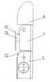
图1是本发明提供的齿条曲柄滑块式并联耦合欠驱动机器人手指装置的第一种技术方案的侧剖视图。Fig. 1 is a side sectional view of the first technical solution of the rack crank slider type parallel coupling underactuated robot finger device provided by the present invention.
图2是图1的A-A剖视图。Fig. 2 is a cross-sectional view along line A-A of Fig. 1 .
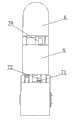
图3是本发明提供的齿条曲柄滑块式并联耦合欠驱动机器人手指装置的第二种技术方案(具有变抓取力效果实施例)的侧剖视图。Fig. 3 is a side sectional view of the second technical solution (an embodiment with variable grasping force effect) of the rack-crank-slider type parallel coupling underactuated robot finger device provided by the present invention.
图4是图3的A-A剖视图的正剖视图。FIG. 4 is a front sectional view of the A-A sectional view of FIG. 3 .
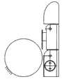
图5是图1所示实施例外观的侧视图。Fig. 5 is a side view of the appearance of the embodiment shown in Fig. 1 .
图6是图1所示实施例外观的正视图。Fig. 6 is a front view of the appearance of the embodiment shown in Fig. 1 .
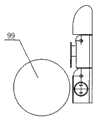
图7、8、9、10是图1所示实施例中实现耦合抓取过程的侧面外观示意图。Figures 7, 8, 9 and 10 are schematic views of the side appearances of the coupled grasping process in the embodiment shown in Figure 1 .
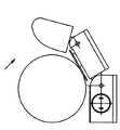
图11、12、13、14是图1所示实施例中实现耦合抓取以及欠驱动自适应抓取过程的侧面外观示意图。11 , 12 , 13 , and 14 are side appearance schematic diagrams of the process of realizing coupled grasping and underactuated adaptive grasping in the embodiment shown in FIG. 1 .
图15、16、17、18是图1所示实施例中实现先耦合后自适应欠驱动的抓取方式过程的侧面外观示意图。15 , 16 , 17 , and 18 are schematic diagrams of the side appearance of the grasping method in the embodiment shown in FIG. 1 , which realizes coupling first and then adaptive underactuation.
在图1至图18中:In Figures 1 to 18:
1-基座, 11-基座架, 12-基座背板,1-base, 11-base frame, 12-base back plate,
121-第一凸块, 13-基座前板, 14-基座右支承板,121-the first bump, 13-base front plate, 14-base right support plate,
15-基座连接板,2-电机, 3-近关节轴,15-base connecting plate, 2-motor, 3-proximal joint shaft,
4-第一指段, 41-第一指段架,42-第一指段背板,4-first finger segment, 41-first finger segment frame, 42-first finger segment backboard,
421-第二凸块, 43-第一指段右支承板,421-the second bump, 43-the first finger segment right bearing plate,
5-远关节轴, 6-第二指段,5-distal joint axis, 6-second finger segment,
71-齿轮, 72-齿条, 73-第一滑块,71-gear, 72-rack, 73-the first slider,
75-第二滑块,751-滑块表面板,78-传动轮,75-the second slide block, 751-slide block surface plate, 78-transmission wheel,
81-第一簧件,82-第二簧件, 83-第三簧件,81-the first spring part, 82-the second spring part, 83-the third spring part,
91-减速器, 94-套筒, 95-销,91-reducer, 94-sleeve, 95-pin,
97-连杆, 98-绳 99-物体。97-connecting rod, 98-rope 99-object.
具体实施方式Detailed ways
下面结合附图及实施例进一步详细说明本发明的具体结构、工作原理及工作过程。The specific structure, working principle and working process of the present invention will be further described in detail below in conjunction with the accompanying drawings and embodiments.
本发明设计的一种齿条曲柄滑块式并联耦合欠驱动机器人手指装置的实施例,剖视图如图1、2所示,外观如图5、6所示,动作原理如图7、8、9、10、11、12、13、14、15、16、17、18所示。本实施例包括基座1、近关节轴3、第一指段4、远关节轴5、第二指段6和电机2,所述的电机2设置在基座1中,电机2的输出轴与近关节轴3相连;所述的近关节轴3套设在所述的基座1中,所述的远关节轴5套设在第一指段4中,所述的第二指段6套固在所述的远关节轴5上;其特征在于:该齿条曲柄滑块式并联耦合欠驱动机器人手指装置还包括齿轮71、传动轮78、第一滑块73、齿条72、第二滑块75、连杆97、第一簧件81和第二簧件82;所述的第一指段4套固在近关节轴3上;所述的齿轮71套设在近关节轴3上,并与基座1固接;所述的传动轮78套固在远关节轴5上,并与第二指段6固接;所述的连杆97一端与第二滑块75铰接,另一端与传动轮78铰接;所述的齿条72与第一滑块73固接,并与齿轮71啮合;在所述的第一指段4中设有相互平行的第一滑槽和第二滑槽,所述的第一滑块73镶嵌在第一滑槽中,抓取物体时沿第一滑槽方向滑动;第二滑块75镶嵌在第二滑槽中,抓取物体时沿第二滑槽方向滑动;所述的第一滑块73与第二滑块75活接触;所述的第一簧件81设置在第一指段4中,第一簧件81的一端与第一指段4相连,另一端与第一滑块73相连;所述的第二簧件82设置在第一指段4中,第二簧件82的两端分别与第一指段4和第二滑块75相连。An embodiment of a rack-crank-slider type parallel coupling underactuated robot finger device designed by the present invention, the cross-sectional view is shown in Figures 1 and 2, the appearance is shown in Figures 5 and 6, and the action principle is shown in Figures 7, 8 and 9 , 10, 11, 12, 13, 14, 15, 16, 17, 18. This embodiment comprises a
本实施例中,所述的第一滑块73与第二滑块75的活接触方式采用单面接触,当第一滑块73向手指里移动时,第一滑块73推动第二滑块75向手指里滑移。当第一指段4碰到物体,第二滑块75向手指里移动时,第二滑块75不会对第一滑块73产生影响,实现了自然解耦。In this embodiment, the living contact between the
本实施例中,所述的第一簧件81采用拉簧,也可以采用压簧或弹性绳,所述的第一簧件81的两端分别连接第一滑块73和第一指段4,所述的第二簧件82采用压簧,也可以采用拉簧或弹性绳,所述的第二簧件82的两端分别连接第二滑块75和第一指段4。In this embodiment, the
本实施例中,还包括传动机构;所述的传动机构包括减速器91、第一齿轮92和第二齿轮93;所述的电机2的输出轴与减速器91的输入轴相连,所述的第一齿轮92套固在减速器91的输出轴上,所述的第二齿轮93套固在近关节轴3上,所述的第一齿轮92与第二齿轮93啮合。In this embodiment, a transmission mechanism is also included; the transmission mechanism includes a
本实施例中,所述的滑块75表面覆盖有滑块表面板751。滑块表面板751表面还可以覆盖有适当弹性的工业橡皮材料。这样在抓取物体时,手指表面与物体之间将形成软指面接触,一方面增加了手指对物体的约束程度,另一方面也可以增加摩擦力,从而增加抓取物体的稳定性。In this embodiment, the surface of the
所述的近关节轴3和第一指段4采用销固接,远关节轴5和第二指段6采用销固接。The proximal
本实施例中,所述的近关节轴3与基座1之间设置有轴承,所述的近关节轴3与齿轮71之间设置有轴承。In this embodiment, a bearing is provided between the joint-
本发明还提供的一种可变抓取力的齿条曲柄滑块式并联耦合欠驱动机器人手指装置的实施例,其剖视图如图4所示。本实施例包括基座1、近关节轴3、第一指段4、远关节轴5、第二指段6和电机2,所述的电机2设置在基座1中,电机2的输出轴与近关节轴3相连;所述的近关节轴3套设在所述的基座1中,所述的远关节轴5套设在第一指段4中,所述的第二指段6套固在所述的远关节轴5上;其特征在于:该齿条曲柄滑块式并联耦合欠驱动机器人手指装置还包括齿轮71、传动轮78、第一滑块73、第二滑块75、第一簧件81、第二簧件82、第三簧件83、齿条72和连杆97;所述的第一指段4套接在近关节轴3上;所述的第三簧件83套在近关节轴3上,两端分别连接第一指段4和近关节轴3;所述的齿轮71套设在近关节轴3上,齿轮71与基座1固接;所述的传动轮78套固在远关节轴5上,传动轮78与第二指段6固接;所述的连杆97一端与传动轮78铰接,另一端与第二滑块75铰接;所述的齿条72与第一滑块73固接,并与第一齿轮71啮合;在所述的第一指段4中设有相互平行的第一滑槽和第二滑槽,所述的第一滑块73镶嵌在第一指段4的第一滑槽中,抓取物体时沿平行于第一滑槽的方向滑动;所述的第二滑块75镶嵌在第一指段4的第二滑槽中,抓取物体时沿平行于第二滑槽的方向滑动;第一滑块73与第二滑块75活接触;所述的第一簧件81设置在第一指段4中,第一簧件81的一端与第一指段4相连,另一端与第一滑块73相连;所述的第二簧件82设置在第一指段4中,第二簧件82的两端分别与第一指段4和第二滑块75相连。The present invention also provides an embodiment of a rack-crank-slider type parallel coupling underactuated robot finger device with variable grasping force, the cross-sectional view of which is shown in FIG. 4 . This embodiment comprises a base 1, a proximal joint shaft 3, a first finger segment 4, a distal joint shaft 5, a second finger segment 6 and a motor 2, the motor 2 is arranged in the base 1, and the output shaft of the motor 2 Connected with the proximal joint shaft 3; the proximal joint shaft 3 is sleeved in the base 1, the distal joint shaft 5 is sleeved in the first finger segment 4, and the second finger segment 6 It is sleeved and fixed on the distal joint shaft 5; it is characterized in that: the rack crank slider type parallel coupling underactuated robot finger device also includes a gear 71, a transmission wheel 78, a first slider 73, and a second slider 75 , the first spring 81, the second spring 82, the third spring 83, the rack 72 and the connecting rod 97; the first finger section 4 is sleeved on the proximal joint shaft 3; the third spring Part 83 is sleeved on the proximal joint shaft 3, and the two ends are respectively connected to the first finger segment 4 and the proximal joint shaft 3; the gear 71 is sleeved on the proximal joint shaft 3, and the gear 71 is fixedly connected to the base 1; The driving wheel 78 is sleeved on the far joint shaft 5, and the driving wheel 78 is fixedly connected with the second finger segment 6; one end of the connecting rod 97 is hinged with the driving wheel 78, and the other end is hinged with the second slide block 75; The rack 72 is affixed to the first slider 73 and meshed with the first gear 71; the first finger section 4 is provided with a first chute and a second chute parallel to each other, and the first chute is parallel to each other. A
所述的第三簧件83的功能是,当电机2带动近关节轴3转动时,套接在近关节轴3上的第三簧件83产生形变,可带动第一指段4转动。The function of the third spring member 83 is that when the
本发明还提供的一种齿条曲柄滑块式并联耦合欠驱动机器人手指装置的实施例,其剖视图如图3所示。第一滑块73与第二滑块75的活接触方式采用绳98连接,当第一滑块73向手指里移动时,第一滑块73拉动第二滑块75向手指里滑移。当第一指段4碰到物体,第二滑块75向手指里移动时,第二滑块75对第一滑块73不会产生影响,实现了自然解耦。The present invention also provides an embodiment of a rack-crank-slider type parallel coupling underactuated robotic finger device, the cross-sectional view of which is shown in FIG. 3 . The living contact between the
下面结合附图介绍图1所示的齿条曲柄滑块式并联耦合欠驱动机器人手指装置的实施例的工作原理。The working principle of the embodiment of the rack-crank-slider type parallel coupling underactuated robot finger device shown in FIG. 1 will be described below with reference to the accompanying drawings.
机器人手指的初始状态如图7所示,电机2停转时,其内部的转动惯量较大,会发生软自锁,所以第一滑块73不会在第一簧件81(第一簧件81采用的是拉簧)的作用下向手指内部移动,此时第一指段4相对于基座1处于伸直状态(第一凸块121顶着第一指段4使手指不至于反向弯曲);第二簧件82采用的是压簧,该压簧迫使第二指段6与第一指段4之间保持伸直的初始状态,即远关节轴5不发生转动(第二凸块421顶着第二指段6),此时整个手指保持伸直状态。The initial state of the robot finger is as shown in Figure 7. When the
本实施例的抓取方式有两种,分别叙述如下:There are two grabbing modes in this embodiment, which are described as follows:
(a)耦合抓取过程(a) Coupled grabbing process
当机器人手指抓取物体99时,电机2正转,通过减速器91带动第一齿轮92转动,驱动第二齿轮93转动,使近关节轴3正转,带动第一指段4绕近关节轴3的中心线正转(此正转方向是指第一指段4逐渐迎向需要抓取的物体)。由于第一齿轮71套接在近关节轴3上且与基座1固接,因此第一指段4的转动,会使得与第一齿条72被第一齿轮71反向拨动(第一齿条72向手指内部平移运动),于是镶嵌在第一指段4中的第一滑块73随着齿条向手指内部平移运动。因为第一滑块73与第二滑块75单面接触,第一滑块73会带动第二滑块75向第一指段4里滑移,第二滑块75把连杆97一端压向手指里,通过连杆97和传动轮78的传动,带动远关节轴5正转,第二指段6正转迎向需要抓取的物体,直到手指接触物体。因此,本实施例在物体不动的情况下实现了耦合抓取的功能。具体运动过程如图7、8、9、10所示。When the robot finger grabs the
放开物体的过程与上述抓取物体的过程相同,电机2反转,将带动第一指段4和第二指段6同时反向转动,实现放开物体,最终回复到手指初始的伸直状态。The process of releasing the object is the same as the above process of grabbing the object. The reverse rotation of the
(b)欠驱动抓取过程(b) Underactuated grasping process
有两种欠驱动抓取过程:There are two underactuated grasping processes:
1)第一种欠驱动抓取过程:其他手指和外力直接挤压物体,物体挤压滑块触发欠驱动抓取,最终第二指段快速扣住物体。具体来说,当第一指段4上可滑动的第二滑块75与物体99接触,第二指段6未与物体接触,物体在其它手指或外力作用下向手指内推动第二滑块75时,第二滑块75向手指里滑移,因为第二滑块75与第一滑块73单面接触,所以不会对第一滑块73产生影响,实现了自然解耦(图3所示实施例采用绳连接方式实现了自然解耦,原理与此相同,不再赘述)。第二滑块75的滑移会把连杆97压向手指里,带动远关节轴5正转,使第二指段6正转直到接触物体实现了抓取,且能够自动适应物体的大小形状,是一种无需电机工作的自适应欠驱动抓取方式。具体运动过程如图11、12、13、14所示。1) The first type of underactuated grasping process: other fingers and external force directly squeeze the object, the object squeezes the slider to trigger underactuated grasping, and finally the second finger quickly buckles the object. Specifically, when the slidable
2)第二种欠驱动抓取过程:物体固定不动(被手掌或其他手指、外力约束),此时本实施例继续转动致使第二滑块因物体阻挡而被压入第一指段中从而触发了欠驱动抓取,最终第二指段快速扣住物体。具体来说,当第一指段4上可滑动的第二滑块与物体99接触,第二指段6未与物体接触,此时由于物体被手掌或其他手指约束住固定不动,滑块被物体阻挡,此时第一指段还可以转动一个很小的角度δ,此转动将产生一个第二指段相对于第一指段的耦合转动角度α(原因见前述的耦合抓取过程),而此时由于滑块已经相对于第一指段向手指内部滑动了一段较小的距离Δd,因此该变化的距离将使得连杆97被压向手指内部,从而带动第二指段转动一个角度θ,由于和相同情况下耦合转动的方式相比,第二滑块75向内移动的距离变大,因此θ会大于α,从而实现第二指段转过的角度是一个较大的角度θ,不再是耦合转动的角度α。此时第二滑块与第一滑块脱开,实现了自然解耦,第二指段快速扣向物体,此过程直到第二指段紧紧扣住物体,从而实现了欠驱动抓取过程。此欠驱动抓取实现了对不同形状大小物体的抓取,具有自适应性,减轻了对控制系统的要求。第二种欠驱动抓取过程如图15、16、17、18所示。2) The second under-actuated grasping process: the object is fixed (constrained by the palm or other fingers, external force), and this embodiment continues to rotate at this time, causing the second slider to be pressed into the first finger segment due to the obstruction of the object This triggers an underactuated grasp and eventually the second segment snaps onto the object. Specifically, when the slidable second slide block on the
综合(a)和(b)耦合和自适应抓取过程可知,本实施例实现了一种特殊的先耦合后自适应欠驱动的抓取方式,解耦方式自然,无需损耗电机功率。Combining (a) and (b) the coupling and adaptive grasping process, it can be known that this embodiment implements a special grasping method that first couples and then adapts to underactuation, and the decoupling method is natural without loss of motor power.
本发明装置利用齿轮、齿条、连杆、双滑块和簧件综合实现了耦合转动与欠驱动转动紧密结合的传动效果,不仅能够耦合转动更拟人化地抓取物体,而且具备欠驱动功能,自适应抓取不同形状、大小的物体;该装置结构简洁紧凑,安装容易,制造加工成本低;该装置耦合传动机构和欠驱动传动机构有机融合,不相互影响,利用滑块活接触的多种方式实现了自然解耦,此解耦不消耗电机功率,能量利用率高。其中第二指段的曲柄滑块机构能够通过主动滑块运动很短的距离实现第二指段大角度的转动。外形与人手手指相似,可以作为拟人机器人手的一个手指或手指的一部分,也可以用多个这样的齿条滑块式并联耦合欠驱动手指组合成为机器人手,用以达到拟人机器人手高关节自由度、高自适应性的优良效果。The device of the present invention utilizes gears, racks, connecting rods, double sliders and springs to comprehensively realize the transmission effect of the close combination of coupling rotation and under-actuated rotation, and can not only grab objects in a more anthropomorphic way through coupled rotation, but also has an under-actuated function , self-adaptively grabbing objects of different shapes and sizes; the device has a simple and compact structure, easy installation, and low manufacturing and processing costs; the coupling transmission mechanism and the underactuated transmission mechanism of the device are organically integrated without mutual influence, and the sliders are used to make more contact with each other. This method realizes natural decoupling, which does not consume motor power and has high energy utilization. Wherein the slider crank mechanism of the second finger section can realize the large-angle rotation of the second finger section through the active slider moving a very short distance. The shape is similar to that of a human finger, and it can be used as a finger or a part of an anthropomorphic robot hand, or a plurality of such rack-slider type parallel coupled underactuated fingers can be combined to form a robot hand to achieve high joint freedom of the anthropomorphic robot hand The excellent effect of high degree and high adaptability.
Claims (8)
Priority Applications (1)
| Application Number | Priority Date | Filing Date | Title |
|---|---|---|---|
| CN2010101648920ACN101829993B (en) | 2010-04-30 | 2010-04-30 | Rack-crank-slider type parallel coupling underactuated robot finger device |
Applications Claiming Priority (1)
| Application Number | Priority Date | Filing Date | Title |
|---|---|---|---|
| CN2010101648920ACN101829993B (en) | 2010-04-30 | 2010-04-30 | Rack-crank-slider type parallel coupling underactuated robot finger device |
Publications (2)
| Publication Number | Publication Date |
|---|---|
| CN101829993Atrue CN101829993A (en) | 2010-09-15 |
| CN101829993B CN101829993B (en) | 2012-05-02 |
Family
ID=42714283
Family Applications (1)
| Application Number | Title | Priority Date | Filing Date |
|---|---|---|---|
| CN2010101648920AExpired - Fee RelatedCN101829993B (en) | 2010-04-30 | 2010-04-30 | Rack-crank-slider type parallel coupling underactuated robot finger device |
Country Status (1)
| Country | Link |
|---|---|
| CN (1) | CN101829993B (en) |
Cited By (6)
| Publication number | Priority date | Publication date | Assignee | Title |
|---|---|---|---|---|
| CN102039598A (en)* | 2010-11-04 | 2011-05-04 | 清华大学 | Dual-connecting rod slider type coupling adaptive under-actuated robot finger device |
| CN105965529A (en)* | 2016-05-19 | 2016-09-28 | 清华大学 | Eccentric wheel, swing rod and sliding groove type coupling self-adaptation robot finger device |
| CN106346508A (en)* | 2016-08-31 | 2017-01-25 | 清华大学 | Four connecting rod driving wheel straight-line parallel-clamping self-adaptive robot finger device |
| CN109664322A (en)* | 2019-01-25 | 2019-04-23 | 合肥工业大学 | A kind of adaptive under-actuated finger device based on link transmission |
| CN110539318A (en)* | 2019-09-10 | 2019-12-06 | 佛山科学技术学院 | An Adaptive Underactuated Gripper Driven by Master-Slave Power |
| CN110802619A (en)* | 2019-10-31 | 2020-02-18 | 天地科技股份有限公司 | Indirect adaptive robot finger device for upper and lower link flat clamps |
Citations (8)
| Publication number | Priority date | Publication date | Assignee | Title |
|---|---|---|---|---|
| JP2001277175A (en)* | 2000-03-30 | 2001-10-09 | Hiroshima Pref Gov | Multi-fingered movable robot hand and its gripping control method |
| CN1410233A (en)* | 2002-11-29 | 2003-04-16 | 清华大学 | Under driving mechanical finger device capable of shape self adaptation |
| CN1410234A (en)* | 2002-11-29 | 2003-04-16 | 清华大学 | Robot anthropomorphic multi finger band device |
| WO2004026540A1 (en)* | 2002-09-02 | 2004-04-01 | Gilles Lopez | Automatic anthropomorphous gripper |
| US20050040664A1 (en)* | 2002-10-07 | 2005-02-24 | Harmonic Drive Systems Inc. | Finger unit for robot hand |
| US6896704B1 (en)* | 1999-05-19 | 2005-05-24 | Harada Electronics Co., Ltd. | Movable finger for prostheses, upper extremity prostheses using this movable finger, and movable finger controller |
| CN101049695A (en)* | 2007-04-27 | 2007-10-10 | 清华大学 | Underactuated drive finger device of imitating cascaded connection of hand of robot |
| CN101518903A (en)* | 2009-03-27 | 2009-09-02 | 清华大学 | Crank block type under-actuated robot finger device |
- 2010
- 2010-04-30CNCN2010101648920Apatent/CN101829993B/ennot_activeExpired - Fee Related
Patent Citations (8)
| Publication number | Priority date | Publication date | Assignee | Title |
|---|---|---|---|---|
| US6896704B1 (en)* | 1999-05-19 | 2005-05-24 | Harada Electronics Co., Ltd. | Movable finger for prostheses, upper extremity prostheses using this movable finger, and movable finger controller |
| JP2001277175A (en)* | 2000-03-30 | 2001-10-09 | Hiroshima Pref Gov | Multi-fingered movable robot hand and its gripping control method |
| WO2004026540A1 (en)* | 2002-09-02 | 2004-04-01 | Gilles Lopez | Automatic anthropomorphous gripper |
| US20050040664A1 (en)* | 2002-10-07 | 2005-02-24 | Harmonic Drive Systems Inc. | Finger unit for robot hand |
| CN1410233A (en)* | 2002-11-29 | 2003-04-16 | 清华大学 | Under driving mechanical finger device capable of shape self adaptation |
| CN1410234A (en)* | 2002-11-29 | 2003-04-16 | 清华大学 | Robot anthropomorphic multi finger band device |
| CN101049695A (en)* | 2007-04-27 | 2007-10-10 | 清华大学 | Underactuated drive finger device of imitating cascaded connection of hand of robot |
| CN101518903A (en)* | 2009-03-27 | 2009-09-02 | 清华大学 | Crank block type under-actuated robot finger device |
Cited By (9)
| Publication number | Priority date | Publication date | Assignee | Title |
|---|---|---|---|---|
| CN102039598A (en)* | 2010-11-04 | 2011-05-04 | 清华大学 | Dual-connecting rod slider type coupling adaptive under-actuated robot finger device |
| CN102039598B (en)* | 2010-11-04 | 2012-05-02 | 清华大学 | Dual-link slider coupling adaptive underactuated robot finger device |
| CN105965529A (en)* | 2016-05-19 | 2016-09-28 | 清华大学 | Eccentric wheel, swing rod and sliding groove type coupling self-adaptation robot finger device |
| CN106346508A (en)* | 2016-08-31 | 2017-01-25 | 清华大学 | Four connecting rod driving wheel straight-line parallel-clamping self-adaptive robot finger device |
| CN106346508B (en)* | 2016-08-31 | 2019-01-18 | 清华大学 | The flat folder indirect self-adaptive robot finger apparatus of double leval jib driving wheel straight line |
| CN109664322A (en)* | 2019-01-25 | 2019-04-23 | 合肥工业大学 | A kind of adaptive under-actuated finger device based on link transmission |
| CN109664322B (en)* | 2019-01-25 | 2021-08-06 | 合肥工业大学 | An adaptive underactuated finger device based on link transmission |
| CN110539318A (en)* | 2019-09-10 | 2019-12-06 | 佛山科学技术学院 | An Adaptive Underactuated Gripper Driven by Master-Slave Power |
| CN110802619A (en)* | 2019-10-31 | 2020-02-18 | 天地科技股份有限公司 | Indirect adaptive robot finger device for upper and lower link flat clamps |
Also Published As
| Publication number | Publication date |
|---|---|
| CN101829993B (en) | 2012-05-02 |
Similar Documents
| Publication | Publication Date | Title |
|---|---|---|
| CN101941205B (en) | Flexible part and slider type parallel coupled under-actuation robot finger device | |
| CN102161204B (en) | Double joint and equidirectional drive hybrid under-actuated robot finger device | |
| CN101693372B (en) | Connecting rod slider-type under-actuated robot finger device with changeable grasping force | |
| CN100551640C (en) | Underactuated robot finger device with tendon rope gear | |
| CN102205542A (en) | Multipath flexible piece two-joint compound robot finger device | |
| CN101829993A (en) | Rack crank slide block type parallel coupling under-driving robot finger device | |
| CN105619440B (en) | Open chain flexible piece puts down folder adaptive robot finger apparatus | |
| CN101829992A (en) | Three-rack slider coupling adaptive underactuated robot finger device | |
| CN101518903B (en) | Crank block type under-actuated robot finger device | |
| CN202241307U (en) | Connecting rod slider type under-actuated bionic robot hand device | |
| CN106426239B (en) | Idle running transmission gear coupling adaptive robot finger apparatus | |
| CN101653941A (en) | Sliding block type direct under-actuated bionic hand device with changeable holding power | |
| CN101367209A (en) | Five-finger type human simulating manipulator mechanism | |
| CN109129530A (en) | Multi-mode grabs the compound adaptive robot finger apparatus of connecting rod in parallel | |
| CN102717393A (en) | Connecting rod coupling-type finger device for neat robot | |
| CN101829994B (en) | Flexible part crank block type parallel coupling underactuated robot finger device | |
| CN101628416B (en) | Two-joint slider type direct underactuated robot finger device with variable grip force | |
| CN101829995A (en) | Crank block type flexible piece parallel coupled under-actuated finger device | |
| CN101214655A (en) | Rack underactuated robotic finger device | |
| CN206393654U (en) | The flat folder indirect self-adaptive robot finger apparatus of rack parallel connection is put in motor | |
| CN101941204B (en) | Double-slider-type parallel coupling under-actuated robot finger device | |
| CN105598992A (en) | Multi-axis wheel train robot finger device for achieving parallel opening and closing and self-adaptive enveloping | |
| CN106426240B (en) | Idle running kinematic link coupling adaptive robot finger apparatus | |
| CN102642210A (en) | Composite under-actuated grasping robot finger device with inverted dual joint motor | |
| CN101941206B (en) | Parallel coupled underactuated finger device with flexible parts and racks |
Legal Events
| Date | Code | Title | Description |
|---|---|---|---|
| C06 | Publication | ||
| PB01 | Publication | ||
| C10 | Entry into substantive examination | ||
| SE01 | Entry into force of request for substantive examination | ||
| C14 | Grant of patent or utility model | ||
| GR01 | Patent grant | ||
| ASS | Succession or assignment of patent right | Owner name:WUXI APPLICATION TECHNOLOGY RESEARCH INSTITUTE OF Free format text:FORMER OWNER: TSINGHUA UNIVERSITY Effective date:20131226 Owner name:TSINGHUA UNIVERSITY Effective date:20131226 | |
| C41 | Transfer of patent application or patent right or utility model | ||
| COR | Change of bibliographic data | Free format text:CORRECT: ADDRESS; FROM: 100084 HAIDIAN, BEIJING TO: 214072 WUXI, JIANGSU PROVINCE | |
| TR01 | Transfer of patent right | Effective date of registration:20131226 Address after:214072 Jiangsu Province Road DiCui Binhu District of Wuxi City No. 100, No. 1 building, 530 floor 12 Patentee after:WUXI RESEARCH INSTITUTE OF APPLIED TECHNOLOGIES, TSINGHUA UNIVERSITY Patentee after:Tsinghua University Address before:100084 Beijing box office,,, Tsinghua University Patentee before:Tsinghua University | |
| CF01 | Termination of patent right due to non-payment of annual fee | Granted publication date:20120502 Termination date:20150430 | |
| EXPY | Termination of patent right or utility model |