CN101829800A - drill - Google Patents
drillDownload PDFInfo
- Publication number
- CN101829800A CN101829800ACN201010130429ACN201010130429ACN101829800ACN 101829800 ACN101829800 ACN 101829800ACN 201010130429 ACN201010130429 ACN 201010130429ACN 201010130429 ACN201010130429 ACN 201010130429ACN 101829800 ACN101829800 ACN 101829800A
- Authority
- CN
- China
- Prior art keywords
- sword
- drill
- maximum gauge
- gauge position
- edge
- Prior art date
- Legal status (The legal status is an assumption and is not a legal conclusion. Google has not performed a legal analysis and makes no representation as to the accuracy of the status listed.)
- Granted
Links
- 230000015572biosynthetic processEffects0.000claimsabstractdescription9
- 238000005520cutting processMethods0.000abstractdescription110
- 230000004888barrier functionEffects0.000abstract1
- 230000008676importEffects0.000abstract1
- 230000000694effectsEffects0.000description5
- 238000005553drillingMethods0.000description3
- 230000007423decreaseEffects0.000description2
- 238000003754machiningMethods0.000description2
- 238000013459approachMethods0.000description1
- 238000010586diagramMethods0.000description1
- 238000000034methodMethods0.000description1
- 230000001629suppressionEffects0.000description1
Images


Classifications
- B—PERFORMING OPERATIONS; TRANSPORTING
- B23—MACHINE TOOLS; METAL-WORKING NOT OTHERWISE PROVIDED FOR
- B23B—TURNING; BORING
- B23B51/00—Tools for drilling machines
- B—PERFORMING OPERATIONS; TRANSPORTING
- B23—MACHINE TOOLS; METAL-WORKING NOT OTHERWISE PROVIDED FOR
- B23B—TURNING; BORING
- B23B2220/00—Details of turning, boring or drilling processes
- B23B2220/24—Finishing
- B—PERFORMING OPERATIONS; TRANSPORTING
- B23—MACHINE TOOLS; METAL-WORKING NOT OTHERWISE PROVIDED FOR
- B23B—TURNING; BORING
- B23B2220/00—Details of turning, boring or drilling processes
- B23B2220/44—Roughing
- B—PERFORMING OPERATIONS; TRANSPORTING
- B23—MACHINE TOOLS; METAL-WORKING NOT OTHERWISE PROVIDED FOR
- B23B—TURNING; BORING
- B23B2251/00—Details of tools for drilling machines
- B23B2251/14—Configuration of the cutting part, i.e. the main cutting edges
- B—PERFORMING OPERATIONS; TRANSPORTING
- B23—MACHINE TOOLS; METAL-WORKING NOT OTHERWISE PROVIDED FOR
- B23B—TURNING; BORING
- B23B2251/00—Details of tools for drilling machines
- B23B2251/20—Number of cutting edges
- B23B2251/204—Four cutting edges
- B—PERFORMING OPERATIONS; TRANSPORTING
- B23—MACHINE TOOLS; METAL-WORKING NOT OTHERWISE PROVIDED FOR
- B23B—TURNING; BORING
- B23B2251/00—Details of tools for drilling machines
- B23B2251/28—Arrangement of teeth
- B23B2251/282—Unequal spacing of cutting edges in the circumferential direction
- Y—GENERAL TAGGING OF NEW TECHNOLOGICAL DEVELOPMENTS; GENERAL TAGGING OF CROSS-SECTIONAL TECHNOLOGIES SPANNING OVER SEVERAL SECTIONS OF THE IPC; TECHNICAL SUBJECTS COVERED BY FORMER USPC CROSS-REFERENCE ART COLLECTIONS [XRACs] AND DIGESTS
- Y10—TECHNICAL SUBJECTS COVERED BY FORMER USPC
- Y10T—TECHNICAL SUBJECTS COVERED BY FORMER US CLASSIFICATION
- Y10T408/00—Cutting by use of rotating axially moving tool
- Y10T408/89—Tool or Tool with support
- Y10T408/905—Having stepped cutting edges
- Y10T408/906—Axially spaced
- Y—GENERAL TAGGING OF NEW TECHNOLOGICAL DEVELOPMENTS; GENERAL TAGGING OF CROSS-SECTIONAL TECHNOLOGIES SPANNING OVER SEVERAL SECTIONS OF THE IPC; TECHNICAL SUBJECTS COVERED BY FORMER USPC CROSS-REFERENCE ART COLLECTIONS [XRACs] AND DIGESTS
- Y10—TECHNICAL SUBJECTS COVERED BY FORMER USPC
- Y10T—TECHNICAL SUBJECTS COVERED BY FORMER US CLASSIFICATION
- Y10T408/00—Cutting by use of rotating axially moving tool
- Y10T408/89—Tool or Tool with support
- Y10T408/909—Having peripherally spaced cutting edges
- Y10T408/9095—Having peripherally spaced cutting edges with axially extending relief channel
Landscapes
- Engineering & Computer Science (AREA)
- Mechanical Engineering (AREA)
- Drilling Tools (AREA)
Abstract
Description
Translated fromChinese技术领域technical field
本发明涉及一种局部具有4个切削刃的钻头。The invention relates to a drill with four cutting edges in part.
背景技术Background technique
众所周知,作为穿孔刀具而利用钻头。大多使用双刃钻头(例如专利文献1)。在双刃钻头中,由于切削刃的个数比较少,所以可以使槽较大地形成,因此切屑的排出性良好。如果切屑的排出性良好,则可以提高钻头的进给速度,可以缩短钻头的穿孔时间。但是,在双刃钻头中,由于切削刃的个数比较少,所以具有切削刃的磨损进展比较快这样的缺点。It is known to use drills as piercing tools. A double-edged drill is often used (for example, Patent Document 1). In the double-edged drill, since the number of cutting edges is relatively small, the flutes can be formed relatively large, so the chip discharge performance is good. If the chip discharge performance is good, the feed rate of the drill can be increased, and the drilling time of the drill can be shortened. However, since the number of cutting edges is relatively small in the double-edged drill, there is a disadvantage that wear of the cutting edges progresses relatively quickly.
图7是典型的4刃钻头的剖面图。在4刃钻头中,与双刃钻头相比较,由于切削刃的个数变多,所以如图7所示,无法使旋转方向切削刃前方的槽较大地形成,使切屑的排出性降低。因此,难以提高钻头的进给速度,难以缩短钻头的穿孔时间。相反地,在4刃钻头中,由于切削刃的个数比较多,所以具有切削刃的磨损进展比较慢的优点,以及可以长期地高品质孔精加工的优点。Figure 7 is a cross-sectional view of a typical 4-flute drill. In a 4-flute drill, since the number of cutting edges is larger than that of a double-blade drill, as shown in FIG. 7 , it is not possible to form a large flute in front of the cutting edge in the direction of rotation, which reduces chip discharge performance. Therefore, it is difficult to increase the feed rate of the drill, and it is difficult to shorten the drilling time of the drill. On the contrary, in the 4-flute drill, since the number of cutting edges is relatively large, there is an advantage that the progress of wear of the cutting edges is relatively slow, and there is an advantage that high-quality hole finishing can be performed over a long period of time.
专利文献1:日本特开2008-36759号公报Patent Document 1: Japanese Patent Laid-Open No. 2008-36759
发明内容Contents of the invention
本发明就是鉴于以上的现有技术而提出的,其课题是提供一种局部具有4个切削刃的钻头,其实现如双刃钻头所示的高切削性能,同时,通过有效且无障碍地导入4个切削刃,与双刃钻头相比实现孔品质的提高、以及长使用寿命化。The present invention is made in view of the above prior art, and its object is to provide a drill with four cutting edges partially, which realizes high cutting performance as shown by a double-edged drill, and at the same time, effectively and without hindrance by introducing With 4 cutting edges, it achieves improved hole quality and longer service life than double-edged drills.
为了解决以上课题,技术方案1记载的发明是一种钻头,其具有由一对主刃构成的双刃结构,该一对主刃彼此形成在相对于中心轴对称的位置上,并且,具有一对副刃,其形成在与所述主刃不同的周方向位置处,且彼此相对于中心轴对称的位置上,所述主刃的轴向形成范围为,从钻头后端侧跨越最大直径位置而直至钻头前端侧,所述副刃的轴向形成范围为,从钻头后端侧跨越最大直径位置而直至钻头前端侧,所述副刃的轴向形成范围的钻头前端侧的末端,与所述主刃的轴向形成范围的钻头前端侧的末端相比,位于钻头后端侧,所述副刃的前端,位于从所述主刃的前端沿钻头旋转方向后方而小于90°的角度范围内,所述主刃以及所述副刃的前端,在最大直径位置以及直至该钻头后端侧,其前端角为0°,且形成在相同半径位置处,从最大直径位置朝向钻头前端侧而前端角逐渐增加,在从最大直径位置开始的一定范围内,所述副刃的前端角增加率比所述主刃的前端角增加率高,由此,在与最大直径位置相比的钻头前端侧,所述副刃的前端与所述主刃的前端相比位于钻头中心侧,并且所述副刃的前端角比所述主刃的前端角大。In order to solve the above problems, the invention described in
技术方案2记载的发明,根据技术方案1所述的钻头,其特征在于,从最大直径位置至至少所述副刃的钻头前端侧的末端为止的轴向范围的所述主刃的前端形状为,在最大直径位置处具有端点、最大直径位置处的切线与钻头中心轴平行的圆弧,从最大直径位置至所述副刃的钻头前端侧的末端为止的轴向范围的所述副刃的前端形状为,在最大直径位置处具有端点、最大直径位置处的切线与钻头中心轴平行的圆弧,所述副刃的所述圆弧的半径与所述主刃的所述圆弧的半径相比较小。The invention described in
发明的效果The effect of the invention
根据本发明,由于首先利用主刃的双刃结构进行切削作业,随着主刃的磨损进展,副刃对被加工孔的切削范围扩大,在副刃的切削范围内,主刃也有效地起到切削作用,所以通过主刃以及副刃这4个切削刃起到切削作用。随着磨损进展,最大直径位置后退。随着磨损进展,主刃以及副刃这4个切削刃的切削范围,以从初始的最大直径位置向钻头前端方向以及钻头后端方向延伸的方式扩大。According to the present invention, since the double-edged structure of the main edge is used for cutting operations at first, as the wear of the main edge progresses, the cutting range of the secondary edge to the hole to be processed is expanded, and the main edge also effectively plays a role in the cutting range of the secondary edge. To the cutting effect, so the cutting effect is played by the four cutting edges of the main edge and the auxiliary edge. As wear progresses, the maximum diameter position recedes. As the wear progresses, the cutting range of the four cutting edges, the main edge and the auxiliary edge, expands from the initial maximum diameter position to the direction of the front end of the drill and the direction of the rear end of the drill.
因此,本发明中的钻头的穿孔作业,首先利用主刃的双刃结构进行切削作业,主刃承担用于穿孔的大部分材料切削作业,完成粗加工,在后方,利用主刃以及副刃这4个切削刃进行精加工。Therefore, the perforation operation of the drill bit in the present invention first utilizes the double-edged structure of the main edge to carry out the cutting operation, and the main edge bears most of the material cutting operation for perforation to complete the rough machining. 4 cutting edges for finishing.
另外,通过与以上的最大直径位置处的磨损进展相伴的4刃化,与双刃钻头相比较,可以进一步抑制如使最大直径位置后退这种磨损进展,将使用寿命长期化。另外,可以抑制与最大直径位置的后退相伴的必要进给量的增加。In addition, the 4-flute that is accompanied by the progress of the wear at the position of the maximum diameter mentioned above can further suppress the progress of wear such as retreating the position of the maximum diameter compared with the double-edged drill, and can prolong the service life. In addition, it is possible to suppress an increase in the necessary feed amount accompanying the retraction of the maximum diameter position.
因此,根据本发明,具有下述效果,即,利用主刃单独的切削范围,可以实现如双刃钻头那样的高切削性能,可以随着磨损进展,顺利且无障碍地导入主刃以及副刃这4个切削刃的切削,可以实现使4个切削刃承担精加工这种有效的导入,从而一边具有如双刃钻头那样的高切削性能,一边与双刃钻头相比实现精加工孔品质的提高、以及长使用寿命化。Therefore, according to the present invention, there is an effect that high cutting performance such as that of a double-edged drill can be realized by using the single cutting range of the main edge, and that the main edge and the auxiliary edge can be introduced smoothly and without hindrance as wear progresses. The cutting of these 4 cutting edges can realize the effective introduction that the 4 cutting edges are responsible for the finishing, so that while having the high cutting performance like the double-edged drill, it can achieve the quality of the finished hole compared with the double-edged drill. Improvement and long service life.
即,根据本发明的钻头,具有下述效果,即,可以在短时间内加工出精加工品质良好的孔,可以对更多的孔进行反复加工。That is, according to the drill bit of the present invention, there is an effect that holes with good finishing quality can be machined in a short time, and more holes can be repeatedly machined.
附图说明Description of drawings
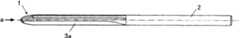
图1是本发明的一个实施方式所涉及的钻头的整体侧视图。FIG. 1 is an overall side view of a drill according to one embodiment of the present invention.
图2是从图1所示的箭头a方向观察的钻头的正视图。Fig. 2 is a front view of the drill viewed from the direction of arrow a shown in Fig. 1 .
图3是从图2所示的箭头b方向观察的钻头的侧视放大图。Fig. 3 is an enlarged side view of the drill viewed from the direction of arrow b shown in Fig. 2 .
图4是从图2所示的箭头c方向观察的钻头的侧视放大图。Fig. 4 is an enlarged side view of the drill viewed from the direction of arrow c shown in Fig. 2 .
图5是在同一平面上描绘本发明的一个实施方式所涉及的钻头的主刃以及副刃的刃尖曲线的示意图。Fig. 5 is a schematic diagram depicting cutting edge curves of the main edge and the auxiliary edge of the drill according to the embodiment of the present invention on the same plane.
图6(a)是图5的部分放大图,(b)是表示其对象部分的磨损进展后的状态的部分放大图。FIG. 6( a ) is a partially enlarged view of FIG. 5 , and FIG. 6( b ) is a partially enlarged view showing a state in which the wear of the target portion progresses.
图7是典型的4刃钻头的剖面图。Figure 7 is a cross-sectional view of a typical 4-flute drill.
具体实施方式Detailed ways
下面,参照附图,说明本发明的一个实施方式。以下是本发明的一个实施方式,并不是限定本发明。Hereinafter, an embodiment of the present invention will be described with reference to the drawings. The following is one embodiment of the present invention, and does not limit the present invention.
如图1所示,本实施方式的钻头具有横刃部1和柄部2。在横刃部1和柄部2之间形成2条直V型槽3a。As shown in FIG. 1 , the drill according to this embodiment has a
如图2所示,在横刃部1上,相对于钻头中心轴对称地设置有一对主刃A、A以及一对副刃B、B。As shown in FIG. 2 , on the
在图2中,箭头d是切削时的钻头旋转方向。主刃A、A分别具有在前端A1彼此相接的前倾面A2以及第二后隙面A3。在第二后隙面A3的旋转方向后方,连续地形成第三后隙面A4。In FIG. 2, arrow d is the direction of rotation of the drill during cutting. The main cutting edges A, A each have a rake surface A2 and a second relief surface A3 that are in contact with each other at the front end A1. A third relief surface A4 is formed continuously behind the second relief surface A3 in the rotational direction.
在前端A1的旋转方向前方形成槽A5。前倾面A2作为槽A5的一侧壁面而形成。如图3所示,槽A5沿钻头轴向与直V型槽3a相连续。A groove A5 is formed forward in the rotational direction of the front end A1. The rake surface A2 is formed as one side wall surface of the groove A5. As shown in Fig. 3, the groove A5 is continuous with the straight V-
如图2所示,槽A5在从前端A1至旋转方向前方的大致90°的范围内较大地形成。As shown in FIG. 2 , the groove A5 is formed largely in a range of approximately 90° from the front end A1 to the front in the rotation direction.
副刃B、B具有分别在前端B1彼此相接的前倾面B2以及后隙面B3。在后隙面B3的旋转方向后方连续地形成槽A5。在前端B1的旋转方向前方形成槽B4。前倾面B2作为槽B4的一侧壁面而形成。如图3所示,槽B4沿钻头轴向与直V型槽3b相连续。The secondary edges B, B have a rake surface B2 and a relief surface B3 that are in contact with each other at the front end B1, respectively. A groove A5 is formed continuously behind the flank B3 in the rotational direction. A groove B4 is formed forward in the rotational direction of the front end B1. The rake surface B2 is formed as one side wall surface of the groove B4. As shown in Fig. 3, the groove B4 is continuous with the straight V-
如图2所示,副刃B的前端B1位于从主刃A的前端A1沿钻头旋转方向后方而小于90°的角度范围内。即,图示的角度θ1、θ2为θ1<90°、θ2>90°。As shown in FIG. 2 , the front end B1 of the secondary cutting edge B is located within an angle range smaller than 90° from the front end A1 of the main cutting edge A to the rear in the drill rotation direction. That is, the illustrated angles θ1 and θ2 are θ1<90° and θ2>90°.
此外,主刃A、A彼此形成在相对于钻头中心轴对称的位置上。即,主刃A、A的前端A1、A1之间的围绕钻头中心轴的相对角为180°。副刃B、B也彼此形成在相对于钻头中心轴对称的位置上。即,副刃B、B的前端B1、B1之间的围绕钻头中心轴的相对角为180°In addition, the main cutting edges A, A are formed at positions symmetrical to each other with respect to the drill center axis. That is, the relative angle around the center axis of the drill between the front ends A1, A1 of the main edges A, A is 180°. The secondary edges B and B are also formed at positions symmetrical to each other with respect to the center axis of the drill. That is, the relative angle around the central axis of the drill between the front ends B1 and B1 of the secondary edges B and B is 180°
。.
如图2~图4所示,在副刃B的钻头轴向前方形成槽B5。槽B5形成为被以下平面切割而成的形态,这些平面包括:与槽B4以及后隙面B3的前端相连续且与钻头中心轴垂直的平面、和与前倾面A2隔着间隔且与前倾面A2平行的平面。As shown in FIGS. 2 to 4 , a groove B5 is formed on the front side of the secondary edge B in the drill axial direction. The groove B5 is formed in a shape cut by planes that are continuous with the front end of the groove B4 and the relief surface B3 and perpendicular to the center axis of the drill bit, and separated from the rake surface A2 and separated from the front end. The inclined plane A2 is parallel to the plane.
下面,说明本实施方式中的钻头的切削刃的轴向形成范围以及刃尖形状。Next, the axial formation range and edge shape of the cutting edge of the drill in this embodiment will be described.
图5表示钻头使用前的初始形状。如图5所示,主刃A形成于从钻头前端部至与最大直径位置E相比的后端侧为止的范围LA内。但是,也可以在钻头前端部留出凿尖(chisel edge)。在此情况下,在从钻头后端侧至凿尖为止的范围内形成主刃A。Figure 5 shows the initial shape of the drill before use. As shown in FIG. 5 , the main cutting edge A is formed within a range LA from the drill front end to the rear end side of the maximum diameter position E. As shown in FIG. However, it is also possible to leave a chisel edge at the front end of the drill bit. In this case, the main cutting edge A is formed in the range from the rear end side of the drill to the chisel tip.
如图5所示,副刃B的轴向形成范围LB,与主刃A相同地,从钻头后端侧跨越最大直径位置E而直至钻头前端侧,但副刃B的轴向形成范围LB的钻头前端侧的末端LB 1,与主刃A的轴向形成范围LA的钻头前端侧的末端LA1相比,位于钻头后端侧。As shown in Fig. 5, the axial forming range LB of the secondary cutting edge B is the same as the main cutting edge A, spanning the maximum diameter position E from the drill rear end side to the drill front end side, but the axial forming range LB of the secondary cutting edge B is The end LB1 on the front end side of the drill is located on the back end side of the drill compared to the end LA1 on the front end side of the drill in the axially forming range LA of the main cutting edge A.
主刃A的轴向形成范围LA的钻头后端侧的末端与副刃B的轴向形成范围LB的钻头后端侧的末端一致。将该一致点在附图上设为点G。与点G相比的钻头后端侧为刃带形成范围M。在范围M内,从点G开始分别与主刃A、A以及副刃B、B相连续地形成刃带。The end of the axially formed area LA of the main edge A on the drill rear end side coincides with the end of the axially formed area LB of the secondary edge B on the drill rear end side. Let this coincident point be point G on the drawing. The rear end side of the drill compared with the point G is the margin formation range M. In the range M, from the point G, the lands are formed continuously with the main edges A, A and the secondary edges B, B, respectively.
如图5所示,主刃A以及副刃B的前端A1、B1,在最大直径位置E以及直至该钻头后端侧的点G为止,前端角均为0°,且形成在相同半径位置处。As shown in Fig. 5, the front ends A1 and B1 of the main cutting edge A and the auxiliary cutting edge B are formed at the same radius position at the maximum diameter position E and up to the point G on the rear end side of the drill with a front end angle of 0°. .
主刃A以及副刃B的前端A1、B1,从最大直径位置E向钻头前端侧,前端角通过连续的变化而单调增加。在这里,“单调增加”表示不排除包含一部分为直线部、即前端角一定的部分,而排除包含前端角减小的部分。另外,“通过连续的变化”是因为没有设置不连续变化而导致的角部。The front ends A1 and B1 of the main cutting edge A and the auxiliary cutting edge B monotonously increase the front end angle by continuous change from the maximum diameter position E toward the front end side of the drill. Here, "increasing monotonically" means not excluding a portion that is a straight portion, that is, a portion with a constant tip angle, but excluding a portion where the tip angle decreases. In addition, "through a continuous change" means that a corner due to a discontinuous change is not provided.
作为主刃A,随着向钻头前端部,其前端角比较平缓地增大。As the main cutting edge A, the front end angle thereof increases relatively gradually toward the front end of the drill.
另一方面,作为副刃B,其从最大直径位置E向钻头前端侧的前端角的增加率,与主刃A的该增加率相比较高,如图5所示,在与最大直径位置E相比的钻头前端侧,副刃B的前端与主刃A的前端相比位于钻头中心侧,并且副刃B的前端角与主刃A的前端角相比较大。On the other hand, as the secondary edge B, the increase rate of the tip angle from the maximum diameter position E to the drill tip side is higher than that of the main edge A. As shown in FIG. Compared to the drill tip side, the tip of the sub-edge B is located on the center side of the drill compared to the tip of the main edge A, and the tip angle of the sub-edge B is larger than that of the main edge A.
例如,如果是在从最大直径位置E至钻头前端侧的范围内,作为副刃B的刃尖形状,使用半径为R1的圆弧形状,作为主刃A的刃尖形状,使用半径为R2的圆弧形状的情况,则设为R1<R2的条件。在此情况下,详细地说,从最大直径位置E至至少副刃B的钻头前端侧的末端LB1为止的轴向范围的主刃A的前端形状为,在最大直径位置E处具有端点、最大直径位置E处的切线与钻头中心轴平行、半径为R2的圆弧。另外,从最大直径位置E至副刃B的钻头前端侧的末端LB1为止的轴向范围的副刃B的前端形状为,在最大直径位置E处具有端点、最大直径位置E处的切线与钻头中心轴平行、半径为R1的圆弧。For example, in the range from the maximum diameter position E to the front end side of the drill, use an arc shape with a radius R1 as the edge shape of the secondary edge B, and use an arc shape with a radius R2 as the edge shape of the main edge A. In the case of an arc shape, the condition of R1<R2 is set. In this case, in detail, the shape of the front end of the main cutting edge A in the axial range from the maximum diameter position E to at least the tip LB1 on the drill front side of the secondary cutting edge B has an end point at the maximum diameter position E and a maximum The tangent at the diameter position E is parallel to the central axis of the drill bit, and the arc with radius R2. In addition, the shape of the front end of the secondary cutting edge B in the axial range from the maximum diameter position E to the tip LB1 on the drill front side of the secondary cutting edge B has an end point at the maximum diameter position E, and the tangent at the maximum diameter position E and the drill A circular arc with parallel central axis and radius R1.
其结果,在末端LB1处,主刃A和副刃B的前端位置产生间隙T(T>0)。As a result, a gap T (T>0) is generated at the tip positions of the main cutting edge A and the secondary cutting edge B at the tip LB1.
与主刃A相比副刃B的从最大直径位置E向钻头前端侧的前端角的增加率较高的范围,可以设为从最大直径位置E至末端LB1为止的范围的整体,也可以设为从最大直径位置E至与末端LB1相比靠近钻头后端的点为止的一部分。即使在后者的情况下,在从最大直径位置E至末端LB1为止的整个范围内,在任意的轴向位置上,均使副刃B的前端B1与主刃A的前端A1相比位于钻头中心侧,并且,使副刃B的前端角与主刃A的前端角相比较大。The range in which the increase rate of the tip angle of the secondary edge B from the maximum diameter position E to the drill tip side is higher than that of the main cutting edge A may be the entire range from the maximum diameter position E to the end LB1, or may be set It is a part from the maximum diameter position E to a point closer to the rear end of the drill than the end LB1. Even in the latter case, in the entire range from the maximum diameter position E to the tip LB1, at any axial position, the front end B1 of the secondary edge B is positioned at the center of the drill bit compared to the front end A1 of the main cutting edge A. The center side, and make the tip angle of the secondary edge B larger than the tip angle of the main edge A.
下面,说明本实施方式中的钻头的作用。Next, the operation of the drill in this embodiment will be described.
如图6(a)所示,在钻头开始使用时,仅利用主刃A进行被切削材料的切削。箭头H表示主刃A的磨损进展方向。As shown in FIG. 6( a ), when the drill starts to be used, only the main edge A is used to cut the workpiece. Arrow H indicates the direction in which the wear of the main cutting edge A progresses.
如图6(b)所示,随着主刃A的磨损进展,最大直径位置E向钻头后端方向后退。与此同时,与最大直径位置E相比钻头前端侧的主刃A的前端A1接近钻头中心侧,从而开始利用副刃B进行的切削。因此,副刃B的切削范围,如箭头e、f所示,从初始的最大直径位置E(图6(a))向钻头前端方向以及钻头后端方向延伸而扩大。图6(b)的点E-点F之间是副刃B的切削范围,并且,是主刃A以及副刃B这4个切削刃的切削范围。如上述所示,由于在图2中θ1<90°、θ2>90°,所以在4个切削刃的范围内,主刃A与副刃B相比切削负荷较大,因此,主刃A较快地磨损。4个切削刃的切削范围E-F随着磨损的进展而进一步扩大。As shown in Fig. 6(b), as the wear of the main cutting edge A progresses, the maximum diameter position E recedes toward the rear end of the drill. At the same time, the tip A1 of the main edge A on the drill tip side approaches the drill center side from the maximum diameter position E, and cutting by the secondary edge B starts. Therefore, the cutting range of the secondary edge B extends from the initial maximum diameter position E ( FIG. 6( a )) toward the front end of the drill and the rear end of the drill as indicated by arrows e and f. The range between point E and point F in FIG. 6( b ) is the cutting range of the secondary edge B, and is the cutting range of four cutting edges, the main edge A and the secondary edge B. As shown above, since θ1<90° and θ2>90° in Fig. 2, within the range of four cutting edges, the cutting load of the main edge A is larger than that of the secondary edge B, therefore, the main edge A is more wears out quickly. The cutting range E-F of the four cutting edges further expands as the wear progresses.
因此,本实施方式中的钻头的穿孔作业,首先利用主刃A的双刃结构进行切削作业,主刃A承担用于穿孔的大部分材料切削作业,完成粗加工,在后方,利用主刃A以及副刃B这4个切削刃进行精加工。Therefore, the drilling operation of the drill in this embodiment first utilizes the double-edged structure of the main edge A to perform the cutting operation. And the four cutting edges of the secondary edge B are finished.
另外,通过与以上的最大直径位置E处的磨损进展相伴的4刃化,与双刃钻头相比较,可以进一步抑制如使最大直径位置E后退这种磨损进展,将使用寿命长期化。另外,可以抑制与最大直径位置E的后退相伴的必要进给量的增加。In addition, the 4-flute that is accompanied by the progress of wear at the maximum diameter position E above can further suppress the progress of wear such as retreating the maximum diameter position E compared to a double-blade drill, and can prolong the service life. In addition, it is possible to suppress an increase in the necessary feed amount accompanying the retraction of the maximum diameter position E.
因此,根据本实施方式的钻头,利用主刃A、A单独的切削范围,可以实现如双刃钻头那样的高切削性能,可以随着磨损进展,顺利且无障碍地导入主刃A以及副刃B这4个切削刃的切削,可以实现使4个切削刃承担精加工这种有效的导入,从而一边具有如双刃钻头那样的高切削性能,一边与双刃钻头相比实现精加工孔品质的提高、以及长使用寿命化。Therefore, according to the drill of this embodiment, it is possible to achieve high cutting performance like a double-edged drill by utilizing the single cutting range of the main edges A and A, and it is possible to introduce the main edge A and the secondary edge smoothly and without hindrance as the wear progresses. The cutting of these 4 cutting edges can realize the effective introduction of finishing machining on the 4 cutting edges, so that while having high cutting performance like the double-edged drill, it can achieve the quality of the finished hole compared with the double-edged drill. Improvement and long service life.
如果在未使用时,使副刃B的前端B 1的半径与主刃A的前端A1一致,则从使用开始,在副刃的形成范围内进行4个切削刃的切削,而产生下述问题,即,主刃在双刃的范围和4刃的范围内,磨损进展显著不同,在双刃和4刃之间的边界处磨损为带台阶的形状,从而过早地变得不能使用。If the radius of the tip B1 of the secondary edge B is made to match the tip A1 of the main edge A when it is not in use, four cutting edges will be cut within the range of the secondary edge from the start of use, and the following problems will arise , that is, the wear progress of the main edge is significantly different between the double-edged range and the 4-edged range, and wears into a stepped shape at the boundary between the double-edged and 4-edged, thereby prematurely becoming unusable.
与此相对,根据本实施方式的钻头,由于随着磨损进展,4个切削刃的切削范围逐渐扩大,双刃和4刃之间的边界不断移动,所以可以使主刃维持顺滑的形状,可以直至到达点G或者末端LB1为止使用4个切削刃的切削范围。On the other hand, according to the drill of this embodiment, since the cutting range of the four cutting edges gradually expands as the wear progresses, and the boundary between the double cutting edge and the four cutting edge moves continuously, the main cutting edge can be maintained in a smooth shape, The cutting range of four cutting edges can be used up to the point G or the end LB1.
根据本实施方式的钻头,可以实现与双刃钻头相同或比其更高的切屑排出性。这是因为设置有与双刃钻头相同程度的大小的槽A5和槽B5。可以设置与双刃钻头相同程度的大小的槽A5的主要原因之一是θ1<90°这一条件。According to the drill of the present embodiment, it is possible to achieve chip discharge performance equal to or higher than that of the double-edged drill. This is because the grooves A5 and B5 having the same size as those of the double-edged drill are provided. One of the main reasons why the groove A5 having the same size as that of the double-edged drill can be provided is the condition of θ1<90°.
另外,由于副刃相对于主刃的角度θ1,不是如现有的4刃钻头那样为θ1=90°,而是在θ1<90°的条件下,可以一定程度地进行选择,所以可以将θ1作为抑振设计的参数,可以构成难共振的钻头。In addition, since the angle θ1 of the secondary cutting edge relative to the main cutting edge is not θ1=90° like the existing 4-flute drill, but can be selected to a certain extent under the condition of θ1<90°, so θ1 can be As a parameter of vibration suppression design, it is possible to construct a drill bit that is difficult to resonate.
此外,不使副刃B的末端LB1延伸至钻头前端是因为,越使末端LB1向钻头前端延伸,则必须使槽B4形成得越深、越大,从而产生切削刃的强度降低的问题。因此,末端LB1与钻头前端相比接近最大直径位置E。In addition, the reason why the tip LB1 of the secondary edge B is not extended to the drill tip is because the deeper and larger the groove B4 must be formed as the tip LB1 is extended toward the drill tip, the problem is that the strength of the cutting edge decreases. Therefore, the end LB1 is closer to the maximum diameter position E than the drill tip.
在以上的实施方式中,使钻头的槽为直槽,但当然也可以为扭转槽。另外,在以上的实施例中,说明了下述例子,即,主刃A和副刃B从钻头前端侧开始前端角为0°的彼此的最大直径位置,配置在相同点(最大直径位置E)上,但本发明不限于此,也可以使彼此的最大直径位置不同,从而使副刃B的最大直径位置与主刃A的最大直径位置相比位于钻头后方侧。In the above embodiments, the grooves of the drill were straight grooves, but of course they may be twisted grooves. In addition, in the above embodiments, an example has been described in which the maximum diameter positions of the main cutting edge A and the secondary cutting edge B are arranged at the same point (maximum diameter position E ), but the present invention is not limited thereto, and the maximum diameter positions may be different from each other so that the maximum diameter position of the secondary edge B is located on the rear side of the drill compared with the maximum diameter position of the main edge A.
Claims (2)
Applications Claiming Priority (2)
| Application Number | Priority Date | Filing Date | Title |
|---|---|---|---|
| JP2009-061009 | 2009-03-13 | ||
| JP2009061009AJP5276486B2 (en) | 2009-03-13 | 2009-03-13 | drill |
Publications (2)
| Publication Number | Publication Date |
|---|---|
| CN101829800Atrue CN101829800A (en) | 2010-09-15 |
| CN101829800B CN101829800B (en) | 2014-12-03 |
Family
ID=42227120
Family Applications (1)
| Application Number | Title | Priority Date | Filing Date |
|---|---|---|---|
| CN201010130429.4AActiveCN101829800B (en) | 2009-03-13 | 2010-03-12 | Drill |
Country Status (6)
| Country | Link |
|---|---|
| US (1) | US8734067B2 (en) |
| EP (1) | EP2228159B1 (en) |
| JP (1) | JP5276486B2 (en) |
| KR (1) | KR101514474B1 (en) |
| CN (1) | CN101829800B (en) |
| ES (1) | ES2573695T3 (en) |
Cited By (1)
| Publication number | Priority date | Publication date | Assignee | Title |
|---|---|---|---|---|
| CN102728870A (en)* | 2011-03-30 | 2012-10-17 | 富士重工业株式会社 | Cutting tool |
Families Citing this family (12)
| Publication number | Priority date | Publication date | Assignee | Title |
|---|---|---|---|---|
| US9180531B2 (en) | 2008-12-23 | 2015-11-10 | Fuji Jukogyo Kabushiki Kaisha | Drill and drilling method for workpiece |
| JP5341502B2 (en)* | 2008-12-26 | 2013-11-13 | 富士重工業株式会社 | drill |
| KR101209737B1 (en) | 2010-10-22 | 2012-12-07 | 현대자동차주식회사 | Variable valve lift system |
| JP5945283B2 (en)* | 2011-12-27 | 2016-07-05 | 住友電気工業株式会社 | drill |
| CN103987482B (en) | 2012-11-09 | 2018-01-12 | 株式会社宫城田野井 | drill bit |
| US10441297B2 (en)* | 2015-05-29 | 2019-10-15 | Zimmer, Inc. | Sounder for sizing bone implant |
| US10028767B2 (en)* | 2016-09-20 | 2018-07-24 | RELIGN Corporation | Arthroscopic devices and methods |
| DE102017216393A1 (en)* | 2017-09-15 | 2019-03-21 | Gühring KG | LOW-DRILLING DRILL |
| JP6727567B1 (en)* | 2019-06-26 | 2020-07-22 | 株式会社ビック・ツール | Carbon fiber composite drill |
| JP7340319B2 (en) | 2019-08-02 | 2023-09-07 | 株式会社Subaru | Manufacturing method of drill and drilled product |
| JP7535368B2 (en) | 2020-09-03 | 2024-08-16 | 株式会社Subaru | Method for manufacturing drill and drilled item |
| JP7569608B2 (en) | 2021-01-28 | 2024-10-18 | 株式会社Subaru | Method for manufacturing drill and drilled item |
Citations (6)
| Publication number | Priority date | Publication date | Assignee | Title |
|---|---|---|---|---|
| US1309706A (en)* | 1919-07-15 | Twist-drill | ||
| US3443459A (en)* | 1968-02-14 | 1969-05-13 | Bruce Alexander Mackey | Drill |
| CN2463091Y (en)* | 2001-04-28 | 2001-12-05 | 倪志福 | Multi-tip and edge group drill |
| DE10346217A1 (en)* | 2003-09-24 | 2005-04-28 | Mapal Fab Praezision | drill |
| CN101062525A (en)* | 2007-04-17 | 2007-10-31 | 湖南大学 | Full-helicoidal surface drilling tip head |
| CN101181806A (en)* | 2006-11-15 | 2008-05-21 | 希尔蒂股份公司 | Drilling tool with hard material head |
Family Cites Families (48)
| Publication number | Priority date | Publication date | Assignee | Title |
|---|---|---|---|---|
| US440532A (en)* | 1890-11-11 | Target-throwing trap | ||
| US1320985A (en)* | 1919-11-04 | Drill-point | ||
| US2084737A (en) | 1935-07-05 | 1937-06-22 | William J Neumann | Reamer |
| US2258674A (en)* | 1940-03-05 | 1941-10-14 | George D Ceska | Reamer |
| JPS5331286A (en)* | 1976-09-02 | 1978-03-24 | Riyousuke Hosoi | Ball end mill |
| US4662803A (en)* | 1979-10-18 | 1987-05-05 | Rockwell International Corporation | Reamer with unequally spaced flutes |
| SU1085702A2 (en) | 1979-12-11 | 1984-04-15 | Предприятие П/Я В-2942 | Shaped drill |
| IT1127526B (en) | 1980-08-01 | 1986-05-21 | Aeritalia Spa | DRILL DRILL TO MAKE LAMINATE HOLES OF FIBER / RESIN COMPOSITE MATERIAL |
| JPS6040328B2 (en) | 1981-01-21 | 1985-09-10 | オ−エスジ−株式会社 | Cutting tools |
| US4411563A (en)* | 1981-07-31 | 1983-10-25 | Elwood Moon | Cutter device |
| US4725171A (en) | 1984-03-02 | 1988-02-16 | Detorre Robert P | Drill for aramid composites |
| JPH0747243B2 (en) | 1987-06-05 | 1995-05-24 | 富士重工業株式会社 | Drills for drilling composite materials |
| DE3805727A1 (en) | 1988-02-24 | 1989-08-31 | Krauss Fa H Willy | DRILLING OR FRICTION TOOL |
| US5141369A (en) | 1988-07-18 | 1992-08-25 | Palace Hilard F | Cutting tool for plastic materials |
| JPH02237708A (en) | 1989-03-09 | 1990-09-20 | Mitsubishi Metal Corp | Drilling tool |
| US4936721A (en)* | 1989-07-03 | 1990-06-26 | Meyer Jerry H | Drill reamer bit |
| JPH0393012U (en)* | 1990-01-10 | 1991-09-24 | ||
| JP2984446B2 (en) | 1992-01-07 | 1999-11-29 | 三菱重工業株式会社 | Drill |
| JPH05245711A (en) | 1992-03-03 | 1993-09-24 | Aisan Ind Co Ltd | Drill |
| JP2790234B2 (en) | 1992-06-25 | 1998-08-27 | 三菱電機株式会社 | Station number duplication test method for programmable controller |
| JPH0639617A (en)* | 1992-07-28 | 1994-02-15 | Fuji Seiko Kk | Burnishing drill |
| SE9202838D0 (en) | 1992-09-30 | 1992-09-30 | Sandvik Ab | Full radius TOOLS |
| JP2602032Y2 (en) | 1993-04-06 | 1999-12-20 | 富士重工業株式会社 | Double angle drill |
| DE4417166B4 (en)* | 1993-07-27 | 2006-02-16 | Mitsubishi Materials Corp. | drill |
| FR2713527B1 (en)* | 1993-12-08 | 1996-01-12 | Snecma | Drill bit with hemispherical head with progressive cut. |
| US5636948A (en) | 1995-05-04 | 1997-06-10 | Fullerton Tool Company, Inc. | Drill for synthetic fiber filled plastic and like materials |
| AUPN839396A0 (en)* | 1996-03-01 | 1996-03-28 | Burton, Victor Edward J. | Drill |
| JPH11114712A (en)* | 1997-10-17 | 1999-04-27 | Kanefusa Corp | Rotary drilling tool |
| DE29919858U1 (en) | 1999-11-11 | 2000-04-27 | Schmid, Harald, 80999 München | Carbide drills |
| JP3450278B2 (en) | 2000-07-24 | 2003-09-22 | 三菱マテリアル神戸ツールズ株式会社 | Drill |
| JP3847109B2 (en)* | 2001-06-19 | 2006-11-15 | 愛三工業株式会社 | Drill |
| EP2366478B1 (en)* | 2001-07-10 | 2020-04-15 | Mitsubishi Materials Corporation | Drill |
| US6676342B2 (en)* | 2002-01-09 | 2004-01-13 | Allied Machine & Engineering Corp. | Drill with specialized drill point geometry |
| DE10204105A1 (en)* | 2002-02-01 | 2003-08-28 | Kennametal Inc | Rotary cutting tool |
| DE20209767U1 (en)* | 2002-06-24 | 2003-11-20 | Gühring, Jörg, Dr., 72458 Albstadt | Spiral drill bit for drilling holes in e.g. plastic, carbon fiber, or other sandwich material with e.g. a titanium layer. has a drill point with two main cutting areas and two intermediate cutters and two main grooves |
| DE10243104A1 (en)* | 2002-09-17 | 2004-03-25 | Gebr. Brasseler Gmbh & Co. Kg | Rotating ceramic tool with a ceramic cutting head bonded to a ceramic or metal support shaft |
| JP2005052939A (en)* | 2003-08-05 | 2005-03-03 | Hitachi Tool Engineering Ltd | Deburring drill |
| FR2861001B1 (en) | 2003-10-16 | 2007-06-22 | Snecma Moteurs | CERAMIC DRILL FOR HIGH SPEED DRILLING |
| JP4746969B2 (en)* | 2005-11-24 | 2011-08-10 | Next I&D株式会社 | Twist drill |
| US7665935B1 (en)* | 2006-07-27 | 2010-02-23 | Precorp, Inc. | Carbide drill bit for composite materials |
| JP5087735B2 (en)* | 2006-08-04 | 2012-12-05 | 富士重工業株式会社 | drill |
| CN101495260B (en)* | 2006-10-23 | 2012-06-13 | Osg株式会社 | Drill head |
| US8714890B2 (en)* | 2007-02-09 | 2014-05-06 | The Boeing Company | Cutter for drilling and reaming |
| JP2009039811A (en)* | 2007-08-08 | 2009-02-26 | Kumamoto Univ | Drilling tools and drilling methods for fiber reinforced composites |
| WO2009155909A2 (en)* | 2008-06-28 | 2009-12-30 | Gühring Ohg | Multiple edge drill |
| JP5245711B2 (en) | 2008-10-17 | 2013-07-24 | 日本電気株式会社 | Distributed data processing system, distributed data processing method, and distributed data processing program |
| US9180531B2 (en)* | 2008-12-23 | 2015-11-10 | Fuji Jukogyo Kabushiki Kaisha | Drill and drilling method for workpiece |
| JP5341502B2 (en) | 2008-12-26 | 2013-11-13 | 富士重工業株式会社 | drill |
- 2009
- 2009-03-13JPJP2009061009Apatent/JP5276486B2/enactiveActive
- 2010
- 2010-02-24KRKR1020100016707Apatent/KR101514474B1/enactiveActive
- 2010-03-02ESES10155199.2Tpatent/ES2573695T3/enactiveActive
- 2010-03-02EPEP10155199.2Apatent/EP2228159B1/enactiveActive
- 2010-03-09USUS12/720,314patent/US8734067B2/enactiveActive
- 2010-03-12CNCN201010130429.4Apatent/CN101829800B/enactiveActive
Patent Citations (6)
| Publication number | Priority date | Publication date | Assignee | Title |
|---|---|---|---|---|
| US1309706A (en)* | 1919-07-15 | Twist-drill | ||
| US3443459A (en)* | 1968-02-14 | 1969-05-13 | Bruce Alexander Mackey | Drill |
| CN2463091Y (en)* | 2001-04-28 | 2001-12-05 | 倪志福 | Multi-tip and edge group drill |
| DE10346217A1 (en)* | 2003-09-24 | 2005-04-28 | Mapal Fab Praezision | drill |
| CN101181806A (en)* | 2006-11-15 | 2008-05-21 | 希尔蒂股份公司 | Drilling tool with hard material head |
| CN101062525A (en)* | 2007-04-17 | 2007-10-31 | 湖南大学 | Full-helicoidal surface drilling tip head |
Cited By (4)
| Publication number | Priority date | Publication date | Assignee | Title |
|---|---|---|---|---|
| CN102728870A (en)* | 2011-03-30 | 2012-10-17 | 富士重工业株式会社 | Cutting tool |
| CN102728870B (en)* | 2011-03-30 | 2016-04-20 | 富士重工业株式会社 | Carbon fibre fortified resin composite cutting tool |
| US9656328B2 (en) | 2011-03-30 | 2017-05-23 | Fuji Jukogyo Kabushiki Kaisha | Cutting tool |
| KR101824678B1 (en) | 2011-03-30 | 2018-02-01 | 가부시키가이샤 수바루 | Cutting tool |
Also Published As
| Publication number | Publication date |
|---|---|
| ES2573695T3 (en) | 2016-06-09 |
| US8734067B2 (en) | 2014-05-27 |
| KR20100103359A (en) | 2010-09-27 |
| JP5276486B2 (en) | 2013-08-28 |
| US20100232899A1 (en) | 2010-09-16 |
| EP2228159B1 (en) | 2016-05-11 |
| EP2228159A8 (en) | 2010-12-15 |
| EP2228159A1 (en) | 2010-09-15 |
| JP2010214478A (en) | 2010-09-30 |
| CN101829800B (en) | 2014-12-03 |
| KR101514474B1 (en) | 2015-04-22 |
Similar Documents
| Publication | Publication Date | Title |
|---|---|---|
| CN101829800A (en) | drill | |
| JP5013435B2 (en) | Ball end mill | |
| JP6086174B2 (en) | drill | |
| WO2010084805A1 (en) | Radius end mill | |
| US9901991B2 (en) | Drill | |
| JP2012511438A (en) | Small drill and method for manufacturing small drill | |
| JP2010105119A (en) | Drill reamer | |
| WO2002040206A1 (en) | Small drill | |
| JP2017202541A (en) | Drill reamer | |
| US10821526B2 (en) | Rotary tool and method for manufacturing machined product | |
| JP2015131384A (en) | drill | |
| JP2010201565A (en) | End mill | |
| JP2005305610A (en) | Twist drill | |
| CN210702730U (en) | Double-edge drill bit | |
| JP2016147328A (en) | drill | |
| JP2008173727A (en) | Drill | |
| JP2010162643A (en) | Drill and grinding method of the drill | |
| JP2005177891A (en) | Drill | |
| JP5444265B2 (en) | Cutting tools | |
| JP2010105092A (en) | Ball end mill | |
| JP2003266225A (en) | Drilling tool | |
| JP5439821B2 (en) | Drill and grinding method of the drill | |
| JP2011125941A (en) | Drill | |
| JP2008080408A (en) | End mill | |
| JP2005169600A (en) | Drill |
Legal Events
| Date | Code | Title | Description |
|---|---|---|---|
| C06 | Publication | ||
| PB01 | Publication | ||
| C10 | Entry into substantive examination | ||
| SE01 | Entry into force of request for substantive examination | ||
| C14 | Grant of patent or utility model | ||
| GR01 | Patent grant | ||
| CP01 | Change in the name or title of a patent holder | ||
| CP01 | Change in the name or title of a patent holder | Address after:Tokyo, Japan Co-patentee after:Makotoloy Co., Ltd. Patentee after:Subaru Co. Address before:Tokyo, Japan Co-patentee before:Makotoloy Co., Ltd. Patentee before:Fuji Heavy Industries, Ltd. | |
| TR01 | Transfer of patent right | ||
| TR01 | Transfer of patent right | Effective date of registration:20171110 Address after:Tokyo, Japan Patentee after:Subaru Co. Address before:Tokyo, Japan Co-patentee before:Makotoloy Co., Ltd. Patentee before:Subaru Co. |