CN101827757B - Pouring member - Google Patents
Pouring memberDownload PDFInfo
- Publication number
- CN101827757B CN101827757BCN2008801122418ACN200880112241ACN101827757BCN 101827757 BCN101827757 BCN 101827757BCN 2008801122418 ACN2008801122418 ACN 2008801122418ACN 200880112241 ACN200880112241 ACN 200880112241ACN 101827757 BCN101827757 BCN 101827757B
- Authority
- CN
- China
- Prior art keywords
- joint
- main body
- injection member
- sealing
- pouring member
- Prior art date
- Legal status (The legal status is an assumption and is not a legal conclusion. Google has not performed a legal analysis and makes no representation as to the accuracy of the status listed.)
- Expired - Fee Related
Links
Images


Classifications
- B—PERFORMING OPERATIONS; TRANSPORTING
- B65—CONVEYING; PACKING; STORING; HANDLING THIN OR FILAMENTARY MATERIAL
- B65D—CONTAINERS FOR STORAGE OR TRANSPORT OF ARTICLES OR MATERIALS, e.g. BAGS, BARRELS, BOTTLES, BOXES, CANS, CARTONS, CRATES, DRUMS, JARS, TANKS, HOPPERS, FORWARDING CONTAINERS; ACCESSORIES, CLOSURES, OR FITTINGS THEREFOR; PACKAGING ELEMENTS; PACKAGES
- B65D41/00—Caps, e.g. crown caps or crown seals, i.e. members having parts arranged for engagement with the external periphery of a neck or wall defining a pouring opening or discharge aperture; Protective cap-like covers for closure members, e.g. decorative covers of metal foil or paper
- B65D41/02—Caps or cap-like covers without lines of weakness, tearing strips, tags, or like opening or removal devices
- B65D41/04—Threaded or like caps or cap-like covers secured by rotation
- B65D41/0471—Threaded or like caps or cap-like covers secured by rotation with means for positioning the cap on the container, or for limiting the movement of the cap, or for preventing accidental loosening of the cap
- B—PERFORMING OPERATIONS; TRANSPORTING
- B65—CONVEYING; PACKING; STORING; HANDLING THIN OR FILAMENTARY MATERIAL
- B65D—CONTAINERS FOR STORAGE OR TRANSPORT OF ARTICLES OR MATERIALS, e.g. BAGS, BARRELS, BOTTLES, BOXES, CANS, CARTONS, CRATES, DRUMS, JARS, TANKS, HOPPERS, FORWARDING CONTAINERS; ACCESSORIES, CLOSURES, OR FITTINGS THEREFOR; PACKAGING ELEMENTS; PACKAGES
- B65D51/00—Closures not otherwise provided for
- B65D51/18—Arrangements of closures with protective outer cap-like covers or of two or more co-operating closures
- B65D51/20—Caps, lids, or covers co-operating with an inner closure arranged to be opened by piercing, cutting, or tearing
- B65D51/22—Caps, lids, or covers co-operating with an inner closure arranged to be opened by piercing, cutting, or tearing having means for piercing, cutting, or tearing the inner closure
- B65D51/228—Caps, lids, or covers co-operating with an inner closure arranged to be opened by piercing, cutting, or tearing having means for piercing, cutting, or tearing the inner closure a major part of the inner closure being removed from the container after the opening
- B—PERFORMING OPERATIONS; TRANSPORTING
- B65—CONVEYING; PACKING; STORING; HANDLING THIN OR FILAMENTARY MATERIAL
- B65D—CONTAINERS FOR STORAGE OR TRANSPORT OF ARTICLES OR MATERIALS, e.g. BAGS, BARRELS, BOTTLES, BOXES, CANS, CARTONS, CRATES, DRUMS, JARS, TANKS, HOPPERS, FORWARDING CONTAINERS; ACCESSORIES, CLOSURES, OR FITTINGS THEREFOR; PACKAGING ELEMENTS; PACKAGES
- B65D75/00—Packages comprising articles or materials partially or wholly enclosed in strips, sheets, blanks, tubes or webs of flexible sheet material, e.g. in folded wrappers
- B65D75/52—Details
- B65D75/58—Opening or contents-removing devices added or incorporated during package manufacture
- B65D75/5861—Spouts
Landscapes
- Engineering & Computer Science (AREA)
- Mechanical Engineering (AREA)
- Closures For Containers (AREA)
- Bag Frames (AREA)
- Infusion, Injection, And Reservoir Apparatuses (AREA)
Abstract
Translated fromChinese
Description
Technical field
The present invention relates on sealing is filled with the container of contents of flowing power, install and form the pouring member of the injection port of contents.
Background technology
At present, be filled with the container of the contents of flowing power, the known container (bag) that the bag shape that flexible packing material bag such as resin molding is formed is arranged as sealing.In medical institutions such as hospital; This bag-like container is many fills the container of enteric nutrient, liquid food, soup etc. with acting on sealing, the patient is supplied with in above-mentioned contents injection, at this moment; Utilize the pouring member of nozzle-like, in patent documentation 1, put down in writing a wherein example.
Patent documentation 1: TOHKEMY 2002-293361 communique.
Summary of the invention
Pouring member shown in the patent documentation 1 (container is used cap device) rotates with respect to injection tube with cap through making sealing, is fastened on sealing with the stop bolt on the cap and twist into two parts, thereby can under hand does not contact the situation of injection tube, wholesomely not open pouring member.
Yet in aforesaid pouring member with opening mechanism, for example, when carrying or when contents are filled in sealing etc., if sealing is with the cap rotation, the stop bolt is twisted into two parts and may be caused contents to leak.Therefore, in use beyond, expectation can suppress to seal the unnecessary rotation with cap.
In addition, the stop bolt is hidden in sealing with in the cap, and when opening, whether the user can't be twisted into two parts with Visual Confirmation stop bolt, therefore, is difficult to judge whether to have accomplished through twisting into two parts of stop bolt open.Therefore; Pointed out to exist as inferior problem: need make sealing with more than cap rotation necessity, waste production time, perhaps under the sealing state that the stop bolt is not twisted into two parts fully with the rotation deficiency of cap; Extract sealing by force and use cap, and cause contents unrestrained.
In addition, when supposing medical institutions such as being used for hospital,, notify the restriction of shape to come the shape of pouring member is limited, thereby prevent the mistake use according to the chief from preventing the viewpoint of malpractice in possible trouble.Therefore, pouring member after will opening inserts in the pipe such as conduit and when contents are supplied with the patient, existence can't with the whole cooresponding difficulties of the conduit of different-diameter.
Thus; For directly can't the conduit in cooresponding bigger footpath; And be used to make the external diameter joint consistent of injection port with the internal diameter of conduit; But in this case, the expectation user can easily identify whether reliably pouring member is installed in the situation on the joint, and relaxing after preventing to install.
In addition; And used in the occupation mode of joint; There is following situation: be inserted at joint under the state of conduit; The container of the supply of the contents that are through with is replaced by new container, perhaps during this period, utilizes conduit chip syringe (カ テ one テ Le チ Star プ シ リ Application ジ) to supply with other soups.Under the situation of so random use joint, require to prevent the deterioration of joint, thereby prevent the generation of leak of liquid with respect to the sealing property of pouring member or conduit chip syringe.Particularly, when using conduit chip syringe to supply with, though the mouth of pipe of conduit chip syringe is pressed on the sealing surface in the joint, the pressing force of this moment can cause the sealing surface in the joint to produce distortion.Therefore, consider the distortion of the sealing surface in this joint, need keep the sealing property of joint with respect to pouring member.
In addition, when being installed to pouring member on the joint, considering to form ridge, thereby install through being spirally connected in the side of injection tube.
Yet different according to the raw material of pipe injection tube directly being inserted when having used the little pipe of the such internal diameter of joint if form such ridge in the side of injection tube, the peristome that has a pipe is pressed off and is gone upward to the situation of ridge.Like this, injected contents leak along the ridge that circles round in the side of injection tube.
For such Guan Eryan, for example can joint be inserted by force, and pouring member etc. is installed, but such complex job not only can become user's burden, also probably causes the damage of pipe at this.
The present invention In view of the foregoing proposes; Its purpose is to provide a kind of pouring member, and it possesses the opening mechanism that can open through the rotation of Kaifeng cover, wherein; Can suppress the to break a seal unnecessary rotation of cover of said pouring member; And judge whether easily to have accomplished to open, and then, can solve and the variety of issue during with joint.
Pouring member of the present invention possesses: the pouring member main body; Be installed in the barrel-contoured Kaifeng of said pouring member main body and end osed top cover with concentric shape, said pouring member main body has: from base portion with cylindric injection tube portion of holding up; The sealing that forms across thinner wall section at the front end of said injection tube portion; Through the said Kaifeng cover that engages with said sealing is rotated around center shaft; And said sealing is twisted into two parts in said thinner wall section; Open said injection tube portion thus, and the end face of the open end side of cover hangs down symmetrically with respect to center shaft and is provided with plural spline sheet from said Kaifeng; Form the recess of front opening in the substantial middle of the Width of said spline sheet; Boundary portion in the said base portion of said pouring member main body and said injection tube portion is provided with flange part, the outstanding locking protrusion that is provided with of the assigned position on said flange part, the said recess of direction almost parallel ground embedding that hangs down of this locking protrusion and said spline sheet.
According to the pouring member of the present invention of said structure, end with the outstanding locking protrusion card that is arranged on the pouring member main body side through making the spline sheet that hangs down from the cover that breaks a seal, can suppress the unnecessary rotation that breaks a seal and cover.And when the card of removing both ended, the vibration transfer when the spline sheet of elastic deformation is replied went out thump (Network リ Star Network) sense at least, and the user can easily learn the zero hour of opening according to thump the sense of this moment.
Description of drawings
Fig. 1 is the instruction diagram of the side-looking side of expression pouring member of the present invention.
Fig. 2 is that the master of expression pouring member of the present invention looks the instruction diagram of side.
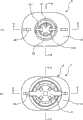
Fig. 3 is the instruction diagram of overlooking side of expression pouring member of the present invention.
Fig. 4 is the instruction diagram of the cooresponding main portion section of A-A section of expression and Fig. 2 (a).
Fig. 5 is the state of Kaifeng cover is pulled down in expression from pouring member a instruction diagram.
Fig. 6 is illustrated in the instruction diagram that is bolted with the state of joint on the pouring member main body.
Fig. 7 is the enlarged drawing of the part shown in the dotted line of Fig. 6 (a).
Fig. 8 is illustrated in the birds-eye view that the pouring member main body is bolted with the state of joint.
Fig. 9 is the elevation profile (F-F section) of expression joint and the instruction diagram that in joint, is inserted with the state of conduit chip syringe.
The specific embodiment
Below, with reference to description of drawings preferred implementation of the present invention.
Fig. 1 is the instruction diagram of side-looking side of the pouring member of this embodiment of expression, and Fig. 2 is that the master of this pouring member of expression looks the instruction diagram of side.
Pouring member 1 shown in the above-mentioned figure possesses pouring membermain body 2 and the Kaifengcover 3 that is installed on the pouring membermain body 2, but of the back, also possesses joint 4 (with reference to Fig. 6).Pouring membermain body 2, Kaifengcover 3 andjoint 4 for example can use thermoplastic base resins such as polyolefin-based resins such as polypropylene, poly-vinyl, make through manufacturing process such as injection moldeds.
Here, Fig. 1 (a) is the lateral plan of pouring member 1, and Fig. 1 (b) is its section-drawing of cutting open of wanting portion.In addition, Fig. 2 is the front view of pouring member 1, and Fig. 2 (b) is the section-drawing of cutting open of its main portion.In addition; The birds-eye view of Fig. 3 (a) expression pouring membermain body 2; The birds-eye view of Fig. 3 (b) expression pouring member 1; B-B section, the D-D section with Fig. 3 (a) is suitable respectively for the section of the pouring membermain body 2 shown in Fig. 1 (b) and Fig. 2 (b) (the represented section of right half part of pouring membermain body 2 among each figure), and C-C section, the E-E section with Fig. 3 (b) is suitable respectively for the section of the Kaifengcover 3 of Fig. 1 (b) and Fig. 2 (b).
In this embodiment, pouring membermain body 2 has:base portion 23, frombase portion 23 to figure the top with cylindricinjection tube portion 22 of holding up,ship shape portion 24 the front end ofinjection tube portion 22 is arranged in figure across sealing 21 thatthinner wall section 21a forms, with respect tobase portion 23 below.As shown in the figure,base portion 23 makes its internal run-through withship shape portion 24 with 22 interior connections of injection tube portion, thereby forms flow ofliquid path 2a.
Theship shape portion 24 of pouring membermain body 2 be when pouring member 1 is installed on container as the injection port of contents as the position of weld part, said container is for example that resin molding is such flexible packing material bag and the bag that forms etc.Threewelding substrate 24a that stretch out about in theship shape portion 24 tool digraphs, be positioned at thelocation substrate 24b ofship shape portion 24 and the boundary portion of base portion 23.And, position through making thelocation substrate 24b and the side butt of the flexible packing material that forms ribbon, simultaneously this flexible packing material is welded to the side ofwelding substrate 24a, thereby pouring member 1 is installed to bag.
On the other hand, Kaifengcover 3 is processed the barrel-contoured member that has been sealed an end bytop board 3a, be installed on the pouring membermain body 2 through sealing tech with the mode that engage with sealing 21, thereby coveringinjection tube portion 22 around.
In addition, in Fig. 1 (a) and Fig. 2 (a), utilize the part of the pouring membermain body 2 that dotted line representes to be covered by thecover 3 that broken a seal.
For making Kaifengcover 3 be fastened on the situation of the sealing 21 of pouring membermain body 2; For example; As shown in the figure, preferably the periphery formation along sealing 21 protrudesflange shape protrusion 21b, and forms theengaging rib 3b that engages with thisprotrusion 21b at the inner peripheral surface of thecover 3 that breaks a seal.Thus, will break aseal cover 3 when being installed in pouring membermain body 2, theengaging rib 3b that being formed on the Kaifengcover 3 crossesprotrusion 21b and the engaging each other that is formed on the sealing 21, the engaging of can realize thus breaking aseal cover 3 and sealing 21.
In addition, be installed in 2 last times of pouring member main body at thecover 3 that will break a seal with concentric shape, through making Kaifengcover 3 around its center shaft rotation, and thesealing 21 that will be sticked in Kaifengcover 3 is twisted into two parts atthinner wall section 21a, thereby opens injection tube portion 22 (with reference to Fig. 5).Thus, the contents in the bag can pass through flow ofliquid path 2a, are injected from the front end ofinjection tube portion 22.
In addition, Fig. 5 is that expression is cut section-drawing open from the portion that wants that injection tube portionmain body 2 is pulled down the state of Kaifengcover 3, expression and the same section of Fig. 1 (b).
For the situation that can utilize Kaifengcover 3 to twist into two parts sealing 21, for example as shown in the figure, preferably form along its radially-protruding a pair ofsheet 21c that stretches out, and the inner peripheral surface ofcover 3 forms card and ends this and stretch out the fasteninggroove 3c ofsheet 21c in Kaifeng at sealing 21.Thus, when making Kaifeng cover 3 around center shaft (about all can) rotation, sealing 21 is rotation thereupon also, thereby can twist into two partsthinner wall section 21.
In addition,, after being twisted into two parts, also can be kept and the engaging of thecover 3 that breaks a seal, thereby can not come off bycover 3 by the sealing 21 twisted into two parts from Kaifeng.
Like this; As long as Kaifengcover 3 is installed in pouring membermain body 2; Under the state that just can be covered by Kaifengcover 3 in theinjection tube portion 22 of pouring membermain body 2; User's finger does not contactinjection tube portion 22 groundinjection tube portion 22 is twisted into two parts and opened to sealing 21, thereby can make the contents injection in the bag.That is, when the user for example only held thebase portion 23 of pouring membermain body 2 through a handgrip, another hand-screw turn-offsealing cover 3 just can wholesomely be twisted into two parts sealing 21 under the situation that does not contactinjection tube portion 22.
In addition, on Kaifengcover 3, be formed with thespline sheet 3d of the unnecessary rotation of being used to suppress to break a seal cover 3.Spline sheet 3d hangs down and forms from the end face of the open end side of Kaifengcover 3, and is as shown in the figure, forms therecess 3e of the front opening that makesspline sheet 3d in the substantial middle of the Width of spline sheet 3d.And the direction almost parallel ground that hangs down of lockingprotrusion 2b through will being formed on pouring membermain body 2 sides andspline sheet 3d embeds thisrecess 3e, and the unnecessary rotation of thecover 3 that can suppress to break a seal is twisted into two parts sealing 21 beyond preventing in use.
In addition, thelocking protrusion 2b that is formed on pouring membermain body 2 sides and thespline sheet 3d that is formed on Kaifengcover 3 also can be used for covering 3 and sealing in the pouring member main body location in 2 last times will break a seal.
In addition,spline sheet 3d is with respect to the center shaft balanced configuration of Kaifeng cover 3.In illustrated example, twospline sheet 3d separate 180 ° of arranged opposite.As shown in the figure, preferably the boundary portion atinjection tube portion 22 andbase portion 23 is provided withflange part 2c, and thelocking protrusion 2b that is formed on pouring membermain body 2 sides gives prominence to the assigned position on the coorespondingflange part 2c ofspline sheet 3d that is arranged on and is formed on the Kaifengcover 3.
In illustrated example, when twisting into two parts sealing 21, make Kaifengcover 3 from the rotation of the state shown in Fig. 4 (a), but this moment,spline sheet 3d is pushed back bylocking protrusion 2b and produces elastic deformation, and releasing simultaneously ends with the card of locking protrusion 2b.Withspline sheet 3d and lockingprotrusion 2b away from and vibration when replying is passed the user with thump propagated sensation.
And then if Kaifeng cover 3 rotates roughly half-turn around center shaft, then as Fig. 4 (b) shown in, thelocking protrusion 2b butt ofspline sheet 3d and opposition side thus, breaks a seal and covers 3 and be in the state that can't further rotate or be difficult to rotate.
Therefore; In the example of Fig. 4 (b); Wall thickness through suitable adjustingthinner wall section 21a or its material etc.; And the anglec of rotation that twisting into two parts of sealing 21 is required is made as less than for example 60 °, thus, can utilize the sense of touch of the rotation that stops Kaifengcover 3 to make the situation of accomplishing or having accomplished of twisting into two parts of learning sealing 21 on user's sense organ.
Promptly; In this mode; Utilize once thump sense that the user is learnt and open the zero hour, under the state of Fig. 4 (b), stop to make the user to learn opening and accomplish constantly, can make thus and learn on user's sense organ that opening the zero hour accomplishes constantly with opening through the rotation that makes Kaifeng cover 3; And can be in the actual completion of opening, and will break a seal and cover 3 states dragged to the top.
In addition, if further from the butt state rotation Kaifengcover 3 of Fig. 4 (b), then lockingprotrusion 2b pushes back and embeds simultaneously recess 3e withspline sheet 3d, thereby ends withspline sheet 3d card, and at this moment, the vibration whenspline sheet 3d replys is passed the user with thump propagated sensation too.
At this moment; As long as suitably regulate wall thickness or its material ofthinner wall section 21a; Just can the anglec of rotation that twisting into two parts of sealing 21 is required be set at, thereby can utilize thump sense (amounting to twice thump sense) once to make the user learn opening the zero hour and opening completion constantly of sealing 21 respectively less than 180 °.
Promptly; Can utilize primary thump sense that the user is learnt opens the zero hour; After in fact twisting into two parts of sealing 21 accomplish; Utilize secondary thump sense to make the situation of accomplishing or having accomplished of twisting into two parts of learning sealing 21 on user's sense organ, and can be in the state that actual opening accomplished and thecover 3 that will break a seal has been dragged to the top.
Thus; When twisting into two parts sealing 21, can avoid with inferior unfavorable condition: makingcover 3 rotations in Kaifeng necessary above and waste production time, perhaps the rotation deficiency of Kaifengcover 3 and sealing 21 twists into two parts under the state that not have completion; Extract Kaifengcover 2 by force, cause contents unrestrained.
Here, the A-A section of section shown in Figure 4 and Fig. 2 is suitable, by long and two-short dash line represent the to break a seal end face of open end side ofcover 3.
At this moment, in Fig. 4 (b), when lockingprotrusion 2b andspline sheet 3d ground as shown in the figure butt, Kaifengcover 3 possibly be in the butt state that can't be further rotated or be difficult to rotate.With respect to this; Shown in Fig. 4 (c), (d), through at least one side with the side of the lateral surface ofrecess 3e or lockingprotrusion 2b process with the medial surface ofrecess 3e likewise, inclined ramp that lockingprotrusion 2b crosses easily or curved surface shape; Become mutual line contact or some contact; Thus,locking protrusion 2b pushes backspline sheet 3d easily,embeds recess 3e simultaneously.In addition, the part that surrounds of the dotted line of Fig. 4 (c), (d) and Fig. 4 (b) is suitable.
In addition,recess 3e can be the poroid of perforation, but is sealed in 2 last times of pouring member main body at thecover 3 that will break a seal, and it is not enough, as shown in the figure that the intensity when bearing axle load becomes, and preferably keeps the bottom side (medial surface of the central side of Kaifeng cover 3) of recess 3e.In addition, through regulating the mesh volume (amount of interference) oflocking protrusion 2b and recess 3e, can be through adjusting so thatlocking protrusion 2b andspline sheet 3d butt orcross spline sheet 3d.
In addition; Thetab 3f that hangs down from the end face of the open end side of Kaifengcover 3 withspline sheet 3d covers 3 and was sealed in 2 last times of pouring member main body will break a seal; Form according to following needs: prevent that Kaifeng cover 3 from tilting; Perhaps strengthen to prevent thatspline sheet 3d from bearing the axle load when sealing and fracture, as shown in Figure 4, avoid forming with the interference of locking protrusion 2b.In addition,tab 3f stipulates and the distance of the central axis direction that engagesrib 3b (short transverse) withspline sheet 3d, is preferably set toprotrusion 21b that can make pouring membermain body 2 and the length that engages the suitable engaging ofrib 3b.
Above-described pouring member 1 can be installed in for example to seal to be filled with on the bags as contents such as enteric nutrient, liquid food and use.Then; Twist into two parts sealing 21 and pull down Kaifengcover 3; The injection tube portion that opens 22 is inserted in the pipes such as being connected to conduit, inject contents afterwards, supply with to the patient; But when supposition is used for the medical institutions such as hospital of above-mentioned that kind, notify the restriction of shape to come the shape ofinjection body 2 is limited according to the chief.Therefore, be difficult to makeinjection body 2 all corresponding with the conduit of different inner diameters, to this, for the internal diameter coupling of the external diameter that makes injection port and conduit, and with joint shown in Figure 64.
Here, Fig. 6 (a) is illustrated in to openinjection tube portion 22 and pull down the portion that wants that the master who is bolted with the state ofjoint 4 on the pouring membermain body 2 behind the Kaifengcover 3 looks side and cut section-drawing open, and Fig. 7 amplifies the part that dotted line surrounds in the presentation graphs.The F-F section of section shown in Fig. 6 (a) (section among the figure shown in the left-half) and Fig. 8 is suitable, but Fig. 8 is the birds-eye view that is bolted with under the state ofjoint 4, and arrow is represented the screw threads for fastening direction ofjoint 4 among the figure.In addition, Fig. 6 (b) is the lateral plan that is bolted with under the state ofjoint 4.
In addition; In illustrated example, in the side ofjoint 4, a pair ofalar part 4a radial symmetry ground that is used to point hook during screw threads for fasteningjoint 4 stretches out formation; Shown in Fig. 6 (b), lower end side is crooked and form abuttingpart 4b to the opposition side of screw threads for fastening direction among the figure of alar part 4a.This abuttingpart 4b is when following situation and lockingprotrusion 2b butt; Promptly; Pouring membermain body 2 is spirally connected withjoint 4, and on the same plane of the center shaft that comprises pouring membermain body 2, theoutstanding locking protrusion 2b that is arranged on theflange part 2c is arranged side by side with thealar part 4a that is formed on thejoint 4.
Through setting like this, can prevent thatjoint 4 is further rotated, and the position of thealar part 4a when limiting screw threads for fastening in advance and accomplishing, thus, only through the visual position that just can confirmalar part 4a, the user can judge easily whether screw threads for fastening is accomplished.
In addition, be formed with aforesaid abuttingpart 4b in the side of the edge ofjoint 4 and the ora terminalis of the opposed side offlange part 2c, and, be formed with thelax locking rib 4c that is used to prevent thejoint 4 that is spirally connected with pouring member main body 2.This lockingrib 4c has the dip plane, and this dip plane uprises towards the opposition side of screw threads for fastening direction apart from the height of the side of joint 4.And when pouring membermain body 2 andjoint 4 were spirally connected, theoutstanding locking protrusion 2b that is arranged on theflange part 2c crossed this dip plane, and falls between lockingrib 4c and theabutting part 4b.
Thus, lockingprotrusion 2b is sandwiched between abuttingpart 4b and the lockingrib 4c, thereby can suppress the opposition side rotation of joint 4 to the screw threads for fastening direction, and prevents that joint 4 is lax.
In addition, utilizeconduit chip syringe 6 to carry out the supply (with reference to Fig. 9) of soup etc. from the joint 4 that is connected to conduit.
Here, the elevation profile of Fig. 9 (a)expression joint 4, Fig. 9 (b) representes the section-drawing of the state on the sealing surface in the joint 4 that the mouth of pipe ofconduit chip syringe 6 is pressed to, the section of the joint 4 shown in the above-mentioned figure is suitable with the F-F section of Fig. 8.
Like this, when supply of chemical etc., shown in Fig. 9 (b); The mouth of pipe ofconduit chip syringe 6 is pressed on the sealing surface in the joint 4; Thereby when improving its leak tightness, carry out from the injection ofconduit chip syringe 6, but if repeatable operation, then the sealing surface of joint 4 may produce distortion.
That is, in illustrated example, shown in Fig. 6 (a), Fig. 9 (a) and Fig. 9 (b), the internal diameter of joint 4 is dwindled towards front at length direction substantial middle place.And, as sealing surface itself andinjection tube portion 22 front ends of pouring membermain body 2 or the mouth of pipe ofconduit chip syringe 6 are connected airtight this reduction face, thereby bring into play its sealing property.Yet; If only will be made as with one side with pouring membermain body 2,conduit chip syringe 6 relative joint 4 interior sealing surfaces like this; Then may produceconduit chip syringe 6 and made the internal diameter of above-mentioned same sealing surface enlarge this situation by driver overadapter 4 by force, on the other hand, because joint 4 utilizes to be spirally connected and is installed on the pouring membermain body 2; Therefore can't append to be pressed into and guarantee sealing property, may cause leakages such as soup.
Therefore, preferably form the outstandingcyclic rib 2d of ring-type as shown in the figure than the forward distolateral position ofridge 2f in the side of injection tube portion 22.And; When pouring membermain body 2 and joint 4 are spirally connected; The inside face of thiscyclic rib 2d and joint 4 connects airtight, and bringing into play sealing property with the sealing surface different at different position and different with respect toconduit chip syringe 6, can keep the sealing property of joint 4 with respect to pouring membermain body 2 thus.
In addition; Difference according to the thickness ofconduit 5, elasticity etc.; Have following situation: the thicker slightly words ofconduit 5 can be via joint 4, and directlyinjection tube portion 22 is insertedconduits 5, relies on the chief and notifies theridge 2f that is provided with under the shape and can be pressed into A/C 5.In addition,conduit 5 is formed etc. by the material of softness, shown in long and two-short dash line among Fig. 5, and the situation that exists the ora terminalis ofconduit 5 to cross threaded portion 2c.Like this, contents may leak along theridge 2f that circles round in the side of injection tube portion 22.Form the connecting airtight property that aforesaidcyclic rib 2d improvesinjection tube portion 22 and the inside face ofconduit 5 in thedirect insertion conduit 5 through the side ininjection tube portion 22, the contents of injection can not flow toridge 2f and prevent that effectively contents from leaking thus.
In addition, with respect to theconduit 5 of path relatively, can utilizeanti-delinking part 2e to improve the connecting airtight property with the inside face ofconduit 5.
More than, in the present invention, explained preferred embodiment, but the present invention is not limited to above-mentioned embodiment, certainly carry out various changes within the scope of the invention and implement.
For example; In illustrated example; Twospline sheet 3d separate 180 ° of formation, but for example when the required anglec of rotation of twisting into two parts of sealing 21 during less than 120 °, also can be through threespline sheet 3d being separated 120 ° and modes such as formation; Utilize secondary thump sense to make the user learn this situation of completion (or accomplishing) of twisting into two parts of sealing 21 as described above; Through modes such as width expansion withspline sheet 3d, the lateral surface ofspline sheet 3d and lockingprotrusion 2b can be whenspline sheet 3d have rotated 120 ° butt, the rotation ofKaifeng cover 3 stops thus.So, as long asspline sheet 3d covers 3 center shaft balanced configuration with respect to breaking a seal, its number can be set arbitrarily according to the required anglec of rotation of twisting into two parts of sealing 21.
Utilizability on the industry
Pouring member of the present invention can be specially adapted to wholesomely to open the container that sealing is filled with contents.
Claims (4)
Translated fromChineseApplications Claiming Priority (3)
| Application Number | Priority Date | Filing Date | Title |
|---|---|---|---|
| JP2007272780AJP4987661B2 (en) | 2007-10-19 | 2007-10-19 | Extraction material |
| JP2007-272780 | 2007-10-19 | ||
| PCT/JP2008/068850WO2009051221A1 (en) | 2007-10-19 | 2008-10-17 | Pouring member |
Publications (2)
| Publication Number | Publication Date |
|---|---|
| CN101827757A CN101827757A (en) | 2010-09-08 |
| CN101827757Btrue CN101827757B (en) | 2012-07-04 |
Family
ID=40567482
Family Applications (1)
| Application Number | Title | Priority Date | Filing Date |
|---|---|---|---|
| CN2008801122418AExpired - Fee RelatedCN101827757B (en) | 2007-10-19 | 2008-10-17 | Pouring member |
Country Status (6)
| Country | Link |
|---|---|
| US (1) | US8434651B2 (en) |
| EP (1) | EP2218651B1 (en) |
| JP (1) | JP4987661B2 (en) |
| KR (1) | KR101514858B1 (en) |
| CN (1) | CN101827757B (en) |
| WO (1) | WO2009051221A1 (en) |
Families Citing this family (59)
| Publication number | Priority date | Publication date | Assignee | Title |
|---|---|---|---|---|
| US10693415B2 (en) | 2007-12-05 | 2020-06-23 | Solaredge Technologies Ltd. | Testing of a photovoltaic panel |
| US11881814B2 (en) | 2005-12-05 | 2024-01-23 | Solaredge Technologies Ltd. | Testing of a photovoltaic panel |
| US11569659B2 (en) | 2006-12-06 | 2023-01-31 | Solaredge Technologies Ltd. | Distributed power harvesting systems using DC power sources |
| US9088178B2 (en) | 2006-12-06 | 2015-07-21 | Solaredge Technologies Ltd | Distributed power harvesting systems using DC power sources |
| US12316274B2 (en) | 2006-12-06 | 2025-05-27 | Solaredge Technologies Ltd. | Pairing of components in a direct current distributed power generation system |
| US11888387B2 (en) | 2006-12-06 | 2024-01-30 | Solaredge Technologies Ltd. | Safety mechanisms, wake up and shutdown methods in distributed power installations |
| US11296650B2 (en) | 2006-12-06 | 2022-04-05 | Solaredge Technologies Ltd. | System and method for protection during inverter shutdown in distributed power installations |
| US8618692B2 (en) | 2007-12-04 | 2013-12-31 | Solaredge Technologies Ltd. | Distributed power system using direct current power sources |
| US8816535B2 (en) | 2007-10-10 | 2014-08-26 | Solaredge Technologies, Ltd. | System and method for protection during inverter shutdown in distributed power installations |
| US11309832B2 (en) | 2006-12-06 | 2022-04-19 | Solaredge Technologies Ltd. | Distributed power harvesting systems using DC power sources |
| US11735910B2 (en) | 2006-12-06 | 2023-08-22 | Solaredge Technologies Ltd. | Distributed power system using direct current power sources |
| US9130401B2 (en) | 2006-12-06 | 2015-09-08 | Solaredge Technologies Ltd. | Distributed power harvesting systems using DC power sources |
| US8013472B2 (en) | 2006-12-06 | 2011-09-06 | Solaredge, Ltd. | Method for distributed power harvesting using DC power sources |
| US11687112B2 (en) | 2006-12-06 | 2023-06-27 | Solaredge Technologies Ltd. | Distributed power harvesting systems using DC power sources |
| US8319471B2 (en) | 2006-12-06 | 2012-11-27 | Solaredge, Ltd. | Battery power delivery module |
| US9112379B2 (en) | 2006-12-06 | 2015-08-18 | Solaredge Technologies Ltd. | Pairing of components in a direct current distributed power generation system |
| US8319483B2 (en) | 2007-08-06 | 2012-11-27 | Solaredge Technologies Ltd. | Digital average input current control in power converter |
| US8947194B2 (en) | 2009-05-26 | 2015-02-03 | Solaredge Technologies Ltd. | Theft detection and prevention in a power generation system |
| US11855231B2 (en) | 2006-12-06 | 2023-12-26 | Solaredge Technologies Ltd. | Distributed power harvesting systems using DC power sources |
| US8963369B2 (en) | 2007-12-04 | 2015-02-24 | Solaredge Technologies Ltd. | Distributed power harvesting systems using DC power sources |
| US8473250B2 (en) | 2006-12-06 | 2013-06-25 | Solaredge, Ltd. | Monitoring of distributed power harvesting systems using DC power sources |
| US8384243B2 (en) | 2007-12-04 | 2013-02-26 | Solaredge Technologies Ltd. | Distributed power harvesting systems using DC power sources |
| WO2009072076A2 (en) | 2007-12-05 | 2009-06-11 | Solaredge Technologies Ltd. | Current sensing on a mosfet |
| CN105244905B (en) | 2007-12-05 | 2019-05-21 | 太阳能安吉有限公司 | Release mechanism in distributed power device is waken up and method for closing |
| US11264947B2 (en) | 2007-12-05 | 2022-03-01 | Solaredge Technologies Ltd. | Testing of a photovoltaic panel |
| US9291696B2 (en) | 2007-12-05 | 2016-03-22 | Solaredge Technologies Ltd. | Photovoltaic system power tracking method |
| WO2009073867A1 (en) | 2007-12-05 | 2009-06-11 | Solaredge, Ltd. | Parallel connected inverters |
| US8111052B2 (en) | 2008-03-24 | 2012-02-07 | Solaredge Technologies Ltd. | Zero voltage switching |
| EP2294669B8 (en) | 2008-05-05 | 2016-12-07 | Solaredge Technologies Ltd. | Direct current power combiner |
| US12418177B2 (en) | 2009-10-24 | 2025-09-16 | Solaredge Technologies Ltd. | Distributed power system using direct current power sources |
| JP5688509B2 (en)* | 2010-09-27 | 2015-03-25 | 株式会社フジシール | Spouted pouch with adapter with cap and adapter with cap |
| JP5552677B2 (en)* | 2010-09-28 | 2014-07-16 | 株式会社フジシール | Adapter and pouch with spout equipped with adapter |
| JP5552678B2 (en)* | 2010-09-28 | 2014-07-16 | 株式会社フジシール | Adapter and pouch with spout equipped with adapter |
| US10673229B2 (en) | 2010-11-09 | 2020-06-02 | Solaredge Technologies Ltd. | Arc detection and prevention in a power generation system |
| US10230310B2 (en) | 2016-04-05 | 2019-03-12 | Solaredge Technologies Ltd | Safety switch for photovoltaic systems |
| US10673222B2 (en) | 2010-11-09 | 2020-06-02 | Solaredge Technologies Ltd. | Arc detection and prevention in a power generation system |
| GB2485527B (en) | 2010-11-09 | 2012-12-19 | Solaredge Technologies Ltd | Arc detection and prevention in a power generation system |
| GB2486408A (en) | 2010-12-09 | 2012-06-20 | Solaredge Technologies Ltd | Disconnection of a string carrying direct current |
| GB2483317B (en) | 2011-01-12 | 2012-08-22 | Solaredge Technologies Ltd | Serially connected inverters |
| US8570005B2 (en) | 2011-09-12 | 2013-10-29 | Solaredge Technologies Ltd. | Direct current link circuit |
| GB2498365A (en) | 2012-01-11 | 2013-07-17 | Solaredge Technologies Ltd | Photovoltaic module |
| GB2498790A (en) | 2012-01-30 | 2013-07-31 | Solaredge Technologies Ltd | Maximising power in a photovoltaic distributed power system |
| US9853565B2 (en) | 2012-01-30 | 2017-12-26 | Solaredge Technologies Ltd. | Maximized power in a photovoltaic distributed power system |
| GB2498791A (en) | 2012-01-30 | 2013-07-31 | Solaredge Technologies Ltd | Photovoltaic panel circuitry |
| GB2499991A (en) | 2012-03-05 | 2013-09-11 | Solaredge Technologies Ltd | DC link circuit for photovoltaic array |
| US10115841B2 (en) | 2012-06-04 | 2018-10-30 | Solaredge Technologies Ltd. | Integrated photovoltaic panel circuitry |
| JP6044985B2 (en)* | 2012-11-07 | 2016-12-14 | 日本クロージャー株式会社 | Break-up spout |
| JP6053462B2 (en)* | 2012-11-09 | 2016-12-27 | 日本クロージャー株式会社 | Break-out spout, spout with spout and method for producing the same |
| JP6060644B2 (en)* | 2012-11-26 | 2017-01-18 | 東洋製罐株式会社 | Extraction material |
| US9941813B2 (en) | 2013-03-14 | 2018-04-10 | Solaredge Technologies Ltd. | High frequency multi-level inverter |
| US9548619B2 (en) | 2013-03-14 | 2017-01-17 | Solaredge Technologies Ltd. | Method and apparatus for storing and depleting energy |
| EP3506370B1 (en) | 2013-03-15 | 2023-12-20 | Solaredge Technologies Ltd. | Bypass mechanism |
| US9318974B2 (en) | 2014-03-26 | 2016-04-19 | Solaredge Technologies Ltd. | Multi-level inverter with flying capacitor topology |
| WO2016141311A1 (en)* | 2015-03-04 | 2016-09-09 | Specialty Lubricants Corp. | Packaging closure adapter |
| US11177663B2 (en) | 2016-04-05 | 2021-11-16 | Solaredge Technologies Ltd. | Chain of power devices |
| US12057807B2 (en) | 2016-04-05 | 2024-08-06 | Solaredge Technologies Ltd. | Chain of power devices |
| US11018623B2 (en) | 2016-04-05 | 2021-05-25 | Solaredge Technologies Ltd. | Safety switch for photovoltaic systems |
| EP3915895A1 (en)* | 2019-02-04 | 2021-12-01 | Tetra Laval Holdings & Finance S.A. | Spout for a package and package-spout assembly |
| KR102860010B1 (en)* | 2023-09-21 | 2025-09-12 | 김숙자 | Safety cap of container |
Citations (4)
| Publication number | Priority date | Publication date | Assignee | Title |
|---|---|---|---|---|
| JPS5846751U (en) | 1981-09-22 | 1983-03-29 | 株式会社リコー | safety container |
| JP2002293361A (en)* | 2001-03-30 | 2002-10-09 | Gomuno Inaki Kk | Container capper |
| CN2839135Y (en)* | 2005-10-28 | 2006-11-22 | 卢嘉颖 | Packaging bag with cover |
| CN101014506A (en)* | 2004-09-09 | 2007-08-08 | 株式会社细川洋行 | Injector and method of manufacturing packaging bag with injector |
Family Cites Families (30)
| Publication number | Priority date | Publication date | Assignee | Title |
|---|---|---|---|---|
| US2762537A (en)* | 1955-04-18 | 1956-09-11 | Boyle Midway Inc | Closure spout |
| US3680745A (en)* | 1971-09-07 | 1972-08-01 | Eyelet Specialty Co | Container construction for a safety closure |
| US3910463A (en)* | 1974-05-08 | 1975-10-07 | Dome Chemical Corp | Closure for liquid container |
| US4002275A (en)* | 1975-11-12 | 1977-01-11 | Vca Corporation | Safety cap |
| US4334638A (en)* | 1980-02-07 | 1982-06-15 | Pacer Technology And Resources, Inc. | Child proof dispenser |
| US4413753A (en)* | 1980-05-15 | 1983-11-08 | Pacer Technology And Resources, Inc. | Dispenser for cyanoacrylate adhesives |
| DE3629289A1 (en)* | 1986-08-28 | 1988-03-10 | Benckiser Gmbh Joh A | CHILD-SAFE SCREW CAP |
| CH681146A5 (en)* | 1990-07-20 | 1993-01-29 | Wilhelm A Keller | |
| US5131571A (en)* | 1991-01-02 | 1992-07-21 | Nolley Roy G | Universal coupling spout apparatus |
| US5249695A (en)* | 1991-03-05 | 1993-10-05 | Portola Packaging, Inc. | Spout fitment closure plug |
| IT221941Z2 (en)* | 1991-10-10 | 1994-12-29 | Sofar Spa | NON-RETURN VALVE CAN BE USED IN PARTICULAR IN A LIQUID PRESSURE DISPENSING CONTAINER |
| EP0579889B1 (en)* | 1992-07-22 | 1997-06-04 | Wilhelm A. Keller | Mixer and attachment |
| NZ259241A (en)* | 1992-12-18 | 1996-12-20 | Schering Corp | Inhaler including a counter ring, a nozzle to break powder agglomerates and spring-biased, bi-directionally rotatable metering plate and powder house |
| FR2707256B1 (en)* | 1993-07-09 | 1995-08-11 | Cebal | Set of a container and a stopper locking together by relative rotation and its use. |
| US5509580A (en)* | 1993-08-30 | 1996-04-23 | Ideal Ideas, Inc. | Child resistant cap for sprayers |
| US5657905A (en)* | 1993-08-30 | 1997-08-19 | Ideal Ideas, Inc. | Child resistant safety cap with collar and semi-flexible tether for sprayers |
| US5975369A (en)* | 1997-06-05 | 1999-11-02 | Erie County Plastics Corporation | Resealable pushable container closure and cover therefor |
| IE980530A1 (en)* | 1998-06-30 | 2000-02-09 | Loctite R & D Ltd | Device for Expressing Substances from a Deformable Tube |
| US6076712A (en)* | 1998-10-22 | 2000-06-20 | Esber; Alex S. | Flexible caulk tube nozzle |
| US6394314B1 (en)* | 1999-10-12 | 2002-05-28 | Discus Dental Impressions, Inc. | Double-barreled syringe with detachable locking mixing tip |
| US6652489B2 (en)* | 2000-02-07 | 2003-11-25 | Medrad, Inc. | Front-loading medical injector and syringes, syringe interfaces, syringe adapters and syringe plungers for use therewith |
| GB2366287B (en)* | 2000-08-31 | 2003-04-23 | Montgomery Daniel & Son Ltd | Liquid container closure assembly |
| US6962275B2 (en)* | 2003-05-19 | 2005-11-08 | Colder Products Company | Fluid coupling with disposable connector body |
| US7040497B2 (en)* | 2003-08-26 | 2006-05-09 | Weiler Engineering, Inc. | Hermetically sealed container with child safety overcap |
| ATE461872T1 (en)* | 2004-02-05 | 2010-04-15 | Ibsa Inst Biochimique Sa | DROPPER BOTTLE |
| CN1980746A (en)* | 2004-07-08 | 2007-06-13 | 米克斯派克系统公开股份有限公司 | Dispensing device for single use |
| JP4635497B2 (en) | 2004-07-15 | 2011-02-23 | 東洋製罐株式会社 | Liquid container dispensing device |
| US7648051B1 (en)* | 2006-08-09 | 2010-01-19 | Rexam Closures And Containers Inc. | Double shell dispensing closure with a reverse tapered drop lug |
| US8870833B2 (en)* | 2007-12-21 | 2014-10-28 | Covidien Lp | Anti-rotation and removal resistant adapter for use with a syringe |
| IN2012DN00919A (en)* | 2009-07-15 | 2015-04-03 | Becton Dickinson Co |
- 2007
- 2007-10-19JPJP2007272780Apatent/JP4987661B2/enactiveActive
- 2008
- 2008-10-17KRKR1020107008029Apatent/KR101514858B1/ennot_activeExpired - Fee Related
- 2008-10-17CNCN2008801122418Apatent/CN101827757B/ennot_activeExpired - Fee Related
- 2008-10-17EPEP08840231.8Apatent/EP2218651B1/ennot_activeNot-in-force
- 2008-10-17USUS12/734,188patent/US8434651B2/ennot_activeExpired - Fee Related
- 2008-10-17WOPCT/JP2008/068850patent/WO2009051221A1/enactiveApplication Filing
Patent Citations (4)
| Publication number | Priority date | Publication date | Assignee | Title |
|---|---|---|---|---|
| JPS5846751U (en) | 1981-09-22 | 1983-03-29 | 株式会社リコー | safety container |
| JP2002293361A (en)* | 2001-03-30 | 2002-10-09 | Gomuno Inaki Kk | Container capper |
| CN101014506A (en)* | 2004-09-09 | 2007-08-08 | 株式会社细川洋行 | Injector and method of manufacturing packaging bag with injector |
| CN2839135Y (en)* | 2005-10-28 | 2006-11-22 | 卢嘉颖 | Packaging bag with cover |
Also Published As
| Publication number | Publication date |
|---|---|
| CN101827757A (en) | 2010-09-08 |
| WO2009051221A1 (en) | 2009-04-23 |
| EP2218651A1 (en) | 2010-08-18 |
| HK1143122A1 (en) | 2010-12-24 |
| EP2218651B1 (en) | 2014-01-22 |
| KR101514858B1 (en) | 2015-04-23 |
| JP4987661B2 (en) | 2012-07-25 |
| JP2009102020A (en) | 2009-05-14 |
| KR20100084155A (en) | 2010-07-23 |
| US20100206915A1 (en) | 2010-08-19 |
| EP2218651A4 (en) | 2012-08-01 |
| US8434651B2 (en) | 2013-05-07 |
Similar Documents
| Publication | Publication Date | Title |
|---|---|---|
| CN101827757B (en) | Pouring member | |
| JP6210967B2 (en) | Closure cap for containers containing liquids, especially enteral nutrient solutions, and containers having such closure caps | |
| JP3247540U (en) | Container for containing nutritional composition | |
| JPH024375A (en) | Vessel apparatus having latchet tooth lock mechanism | |
| BR112017000498B1 (en) | NOZZLE ASSEMBLY FOR FLEXIBLE BAG | |
| US10737861B2 (en) | Spout for a flexible bag and flexible bag having a spout | |
| CN104176365B (en) | Leakless beverage bottle | |
| CN216685605U (en) | Plastic bottle cap structure capable of preventing anti-theft ring from breaking in advance | |
| CN101721309A (en) | Infusion bag and infusion apparatus matched with same | |
| JP6442415B2 (en) | Open container cap assembly | |
| CN206828057U (en) | A kind of bottle opener | |
| JP5055040B2 (en) | Spout | |
| CN207078500U (en) | Aluminum point mouth cleaning hose with the false proof cap of draw-ring type | |
| CN101391686B (en) | Lotion pump sealing device | |
| CN108313382B (en) | A mechanical leak-proof quick-change device for a medicine dispensing device | |
| CN206822848U (en) | A kind of mixed medicine joint, combined type medicine mixer and transfusion flexible bag | |
| CN201375674Y (en) | Infusion bag and infusion set for assorted use with same | |
| JP2012056632A (en) | Sealing device | |
| CN208070129U (en) | A kind of dispensing device mechanical leak-proof fast replacing device | |
| CN221808267U (en) | Detachable plastic needle infusion set | |
| CN206597164U (en) | A kind of infusion vessel external member for being easy to position | |
| JP2019201996A (en) | Dosage container nozzle and dosage container | |
| JP5688509B2 (en) | Spouted pouch with adapter with cap and adapter with cap | |
| CN208626232U (en) | Anti-leakage infusion bottles and anti-leakage infusion equipment | |
| CN209596212U (en) | A kind of liquid-leakage preventing liquid separation bag easy to use |
Legal Events
| Date | Code | Title | Description |
|---|---|---|---|
| C06 | Publication | ||
| PB01 | Publication | ||
| C10 | Entry into substantive examination | ||
| SE01 | Entry into force of request for substantive examination | ||
| REG | Reference to a national code | Ref country code:HK Ref legal event code:DE Ref document number:1143122 Country of ref document:HK | |
| C53 | Correction of patent of invention or patent application | ||
| CB02 | Change of applicant information | Address after:Tokyo, Japan Applicant after:TOYO SEIKAN Co.,Ltd. Co-applicant after:MEIJI Co.,Ltd. Address before:Tokyo, Japan Applicant before:TOYO SEIKAN Co.,Ltd. Co-applicant before:MEIJI DAIRIES Corp. | |
| C14 | Grant of patent or utility model | ||
| GR01 | Patent grant | ||
| REG | Reference to a national code | Ref country code:HK Ref legal event code:GR Ref document number:1143122 Country of ref document:HK | |
| CF01 | Termination of patent right due to non-payment of annual fee | Granted publication date:20120704 |