CN101825736B - Enhanced prism sheet - Google Patents
Enhanced prism sheetDownload PDFInfo
- Publication number
- CN101825736B CN101825736BCN200910079139.9ACN200910079139ACN101825736BCN 101825736 BCN101825736 BCN 101825736BCN 200910079139 ACN200910079139 ACN 200910079139ACN 101825736 BCN101825736 BCN 101825736B
- Authority
- CN
- China
- Prior art keywords
- frustum
- light
- prism film
- cylindrical body
- adjacent
- Prior art date
- Legal status (The legal status is an assumption and is not a legal conclusion. Google has not performed a legal analysis and makes no representation as to the accuracy of the status listed.)
- Expired - Fee Related
Links
Images


Classifications
- G—PHYSICS
- G02—OPTICS
- G02B—OPTICAL ELEMENTS, SYSTEMS OR APPARATUS
- G02B5/00—Optical elements other than lenses
- G02B5/04—Prisms
- G02B5/045—Prism arrays
- G—PHYSICS
- G02—OPTICS
- G02B—OPTICAL ELEMENTS, SYSTEMS OR APPARATUS
- G02B6/00—Light guides; Structural details of arrangements comprising light guides and other optical elements, e.g. couplings
- G02B6/0001—Light guides; Structural details of arrangements comprising light guides and other optical elements, e.g. couplings specially adapted for lighting devices or systems
- G02B6/0011—Light guides; Structural details of arrangements comprising light guides and other optical elements, e.g. couplings specially adapted for lighting devices or systems the light guides being planar or of plate-like form
- G02B6/0033—Means for improving the coupling-out of light from the light guide
- G02B6/005—Means for improving the coupling-out of light from the light guide provided by one optical element, or plurality thereof, placed on the light output side of the light guide
- G02B6/0053—Prismatic sheet or layer; Brightness enhancement element, sheet or layer
Landscapes
- Physics & Mathematics (AREA)
- General Physics & Mathematics (AREA)
- Optics & Photonics (AREA)
- Optical Elements Other Than Lenses (AREA)
Abstract
Translated fromChinese
Description
Translated fromChinese技术领域technical field
本发明涉及一种液晶显示器中背光源的光学结构膜,特别是一种增强棱镜膜。The invention relates to an optical structure film of a backlight source in a liquid crystal display, in particular to an enhanced prism film.
背景技术Background technique
目前,液晶显示器中的背光源均设置有光学结构膜,光学结构膜起到增强亮度和扩大视角等作用。图11为现有技术背光源的光学结构膜的结构示意图,为一种边缘照明结构形式。如图11所示,背光源的光学结构膜主要包括导光板10、扩散膜20和棱镜膜30,位于光学结构膜侧面的光源40提供照明光线50,照明光线50通过导光板10改变光线方向,从导光板10出射的光线进入棱镜膜30后,棱镜膜30通过光折射和全反射,使从棱镜膜30射出的光线集中于一个较小的角度内,起到增加亮度的作用。At present, the backlight source in the liquid crystal display is provided with an optical structure film, and the optical structure film plays the role of enhancing the brightness and expanding the viewing angle. FIG. 11 is a structural schematic diagram of an optical structure film of a backlight source in the prior art, which is a kind of edge lighting structure. As shown in FIG. 11 , the optical structural film of the backlight mainly includes a
目前,现有技术的棱镜膜的结构是沿相同方向依次排列的长条形棱镜,长条形棱镜的截面为等腰直角三角形。实际应用表明,现有技术这种结构形式的棱镜膜存在轴向方向视角较小问题。这是由于在长条形棱镜的轴向方向,现有技术的棱镜膜是直线形,仅能引导某一个固定方向的照明光线,使照明光线从棱镜膜的法线方向射出,而对其它方向光线的引导作用较差,而且当棱镜膜内的光线以超过全反射角入射到长条形棱镜的上表面时,光线发生全反射,使光线不能射出。因此,当视角较大时,现有技术棱镜膜轴向方向的亮度下降非常快,几乎下降到原来的20%左右,对观看效果影响相当大。虽然现有技术通过细化棱镜尺寸、复合结构搭配等手段不断改善视角问题,但都没有获得较好的效果。At present, the structure of the prism film in the prior art is strip-shaped prisms arranged in sequence along the same direction, and the cross-section of the strip-shaped prisms is an isosceles right-angled triangle. Practical application shows that the prism film with this structure in the prior art has the problem of small viewing angle in the axial direction. This is because in the axial direction of the elongated prism, the prism film of the prior art is linear, and can only guide the illumination light in a certain fixed direction, so that the illumination light is emitted from the normal direction of the prism film, while for other directions The guiding function of the light is poor, and when the light in the prism film is incident on the upper surface of the elongated prism at an angle exceeding the total reflection, the light is totally reflected so that the light cannot be emitted. Therefore, when the viewing angle is large, the luminance in the axial direction of the prism film in the prior art decreases very quickly, almost to about 20% of the original value, which greatly affects the viewing effect. Although the existing technology has continuously improved the viewing angle problem by means of refining the size of the prism and matching the composite structure, none of them have achieved good results.
发明内容Contents of the invention
本发明的目的是提供一种增强棱镜膜,有效解决现有技术棱镜膜轴向方向视角较小等技术缺陷。The purpose of the present invention is to provide an enhanced prism film, which can effectively solve the technical defects of the prior art prism film such as a small axial viewing angle.
为了实现上述目的,本发明提供了一种增强棱镜膜,包括数个沿第一方向延伸的柱形体,所述数个柱形体沿第二方向对接,形成具有从两个方向起聚光作用的出光面。In order to achieve the above object, the present invention provides an enhanced prism film, which includes several cylindrical bodies extending along the first direction, and the several cylindrical bodies are butted along the second direction to form a prism with the function of concentrating light from two directions. light surface.
所述柱形体包括数个依次连接的第一锥台和第二锥台,每个第一锥台的锥底与相邻第二锥台的锥底对接,每个第一锥台的锥顶与相邻第二锥台的锥顶对接,形成一种类似螺纹结构的柱形体。进一步地,所述第一锥台或第二锥台的锥底的宽度为50μm~100μm,锥顶的宽度为20μm~60μm。所述第一锥台或第二锥台的高度为10μm~50μm。所述第一锥台或第二锥台的锥底与母线之间的夹角为30°~60°。The cylindrical body includes several successively connected first frustums and second frustums, the bottom of each first frustum abuts with the bottom of the adjacent second frustum, and the top of each first frustum It abuts with the apex of the adjacent second truncated cone to form a cylindrical body similar to a thread structure. Further, the width of the base of the first frustum or the second frustum is 50 μm to 100 μm, and the width of the apex is 20 μm to 60 μm. The height of the first frustum or the second frustum is 10 μm˜50 μm. The included angle between the bottom of the first frustum or the second frustum and the generatrix is 30°-60°.
每个类似螺纹结构的柱形体上的第一锥台与相邻柱形体上的第二锥台对接,形成一种相邻的类似螺纹结构的柱形体相互啮合的平面体。The first frustum on each thread-like cylindrical body is docked with the second tapered frustum on an adjacent cylindrical body to form a planar body in which adjacent cylindrical bodies with a thread-like structure engage with each other.
在上述技术方案基础上,沿所述第一方向,所述出光面的截面为依次连接的数个三角形,沿所述第二方向,所述出光面的截面为依次连接的数个弧形。进一步地,所述弧形为半圆形、半椭圆形、圆冠形或椭圆冠形。On the basis of the above technical solution, along the first direction, the cross-section of the light-emitting surface is several triangles connected in sequence, and along the second direction, the cross-section of the light-emitting surface is several arcs connected in sequence. Further, the arc is semicircle, semiellipse, round crown or ellipse crown.
在上述技术方案基础上,所述第一锥台和第二锥台的锥底与所述第二方向具有夹角δ,且0°≤δ≤45°,或-45°≤δ≤0°。或对于相邻的两个柱形体,一个柱形体中第一锥台和第二锥台的锥底与所述第二方向具有夹角δ1,且0°≤δ1≤45°,另一个柱形体中第一锥台和第二锥台的锥底与所述第二方向具有夹角δ2,且-45°≤δ2≤0°。On the basis of the above technical solution, the bottom of the first frustum and the second frustum have an included angle δ with the second direction, and 0°≤δ≤45°, or -45°≤δ≤0° . Or for two adjacent cylindrical bodies, the cone bases of the first frustum and the second frustum in one cylindrical body have an included angle δ1 with the second direction, and 0°≤δ1≤45°, and the other cylindrical body The bottoms of the first frustum and the second frustum have an included angle δ2 with the second direction, and -45°≤δ2≤0°.
本发明提出了一种增强棱镜膜,其出光面是由沿第一方向延伸的数个弧形和沿第二方向延伸的数个三角形构成的三维表面,有效解决了现有技术棱镜膜视角较小的技术缺陷。与现有技术相比,由于增强棱镜膜沿第二方向的上表面形状为弧线形,因此本发明增强棱镜膜不仅没有出现±45°视角附近的死区,而且在±45°视角附近亮度缓慢下降,到±60°视角附近还能保证较高的亮度,具有良好的聚光作用,且起到了扩大视角的作用。此外,由于增强棱镜膜的出光面是一种不连续的曲面结构,整个出光面由数个微出光结构组成,反映到宏观上是一种随机分布,可有效避免出射光的光干涉现象。The invention proposes an enhanced prism film, the light-emitting surface of which is a three-dimensional surface composed of several arcs extending along the first direction and several triangles extending along the second direction, which effectively solves the problem of the relatively large viewing angle of the prism film in the prior art. Minor technical flaws. Compared with the prior art, since the shape of the upper surface of the enhanced prism film along the second direction is arc-shaped, the enhanced prism film of the present invention not only does not have a dead zone near the viewing angle of ±45°, but also has a brightness near the viewing angle of ±45°. Slowly descending, it can also ensure high brightness near the viewing angle of ±60°, has a good light-gathering effect, and plays a role in expanding the viewing angle. In addition, since the light-emitting surface of the enhanced prism film is a discontinuous curved surface structure, the entire light-emitting surface is composed of several micro-light-emitting structures, which reflect a random distribution on the macroscopic level, which can effectively avoid light interference of the outgoing light.
附图说明Description of drawings
图1为本发明增强棱镜膜第一实施例的结构示意图;Fig. 1 is the structural representation of the first embodiment of the enhanced prism film of the present invention;
图2为图1中A-A向剖视图;Fig. 2 is A-A direction sectional view in Fig. 1;
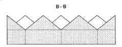
图3为图1中B-B向告视图;Fig. 3 is the B-B report view in Fig. 1;
图4为本发明增强棱镜膜第一实施例第二方向聚光作用的原理图;Fig. 4 is a schematic diagram of the second-direction light-gathering effect of the first embodiment of the enhanced prism film of the present invention;
图5为本发明增强棱镜膜第一实施例第二方向聚光作用的效果图;Fig. 5 is an effect diagram of the light concentrating effect in the second direction of the first embodiment of the enhanced prism film of the present invention;
图6为本发明增强棱镜膜第一实施例第一方向聚光作用的原理图;Fig. 6 is a schematic diagram of the light concentrating effect in the first direction of the first embodiment of the enhanced prism film of the present invention;
图7为本发明增强棱镜膜第一实施例第一方向聚光作用的效果图;Fig. 7 is an effect diagram of the light concentrating effect in the first direction of the first embodiment of the enhanced prism film of the present invention;
图8为本发明增强棱镜膜第一实施例的平面图;8 is a plan view of the first embodiment of the enhanced prism film of the present invention;
图9为本发明增强棱镜膜第二实施例的结构示意图;9 is a schematic structural view of the second embodiment of the enhanced prism film of the present invention;
图10为本发明增强棱镜膜第三实施例的结构示意图;Fig. 10 is a schematic structural view of the third embodiment of the enhanced prism film of the present invention;
图11为现有技术背光源的光学结构膜的结构示意图。FIG. 11 is a schematic structural view of an optical structure film of a backlight source in the prior art.
附图标记说明:Explanation of reference signs:
1-柱形体; 11-第一锥台; 12-第二锥台; 10-导光板;1-cylindrical body; 11-the first cone; 12-the second cone; 10-light guide plate;
20-扩散膜; 30-棱镜膜; 40-光源; 50-照明光线。20-diffusion film; 30-prism film; 40-light source; 50-illumination light.
具体实施方式Detailed ways
下面通过附图和实施例,对本发明的技术方案做进一步的详细描述。The technical solutions of the present invention will be described in further detail below with reference to the accompanying drawings and embodiments.
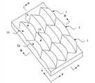
图1为本发明增强棱镜膜第一实施例的结构示意图。如图1所示,本实施例增强棱镜膜包括数个柱形体1,每个柱形体1由数个第一锥台11和第二锥台12组成,第一锥台11和第二锥台12依次连接并沿第一方向X延伸,每个第一锥台11的锥底与相邻第二锥台12的锥底对接,每个第一锥台11的锥顶与相邻第二锥台12的锥顶对接,形成一种类似直螺纹结构的柱形体。数个柱形体1沿第二方向Y依次对接,每个柱形体1上的第一锥台11与相邻柱形体1上的第二锥台12对接,形成一种由类似直螺纹结构的柱形体相互啮合的平面体,本实施例中,第一方向X与第二方向Y垂直,第一锥台11和第二锥台12均为等腰的正锥台,即锥顶与锥底平行,锥底与两侧母线的夹角相同。这样,沿第一方向X延伸并沿第二方向Y对接的数个柱形体构成具有三维形状的上表面,形成本发明具有从两个方向起聚光作用出光面的增强棱镜膜。FIG. 1 is a schematic structural view of the first embodiment of the enhanced prism film of the present invention. As shown in Figure 1, the enhanced prism film of the present embodiment includes several
图2为图1中A-A向剖视图。如图2所示,本发明柱形体1沿第二方向Y的截面形状由位于下方的矩形和位于上方的弧形构成,本实施例的弧形采用半圆形,实际应用中还可以采用半椭圆形、圆冠形、椭圆冠形或本领域技术人员惯常采用的曲线形状,还可以采用由多边形组成的类弧形。因此,本实施例增强棱镜膜沿第二方向Y的截面形状中,下部边为直线,上部边为依次连接的数个弧形。实际应用中,下部边组成的面作为本实施例增强棱镜膜的入光面,上部边组成的面作为本实施例增强棱镜膜的出光面。图3为图1中B-B向剖视图。如图3所示,由于本实施例柱形体1由相对设置的第一锥台11和第二锥台12依次连接构成,因此本实施例增强棱镜膜沿第一方向X的截面形状中,下部边为直线,上部边为依次连接的数个三角形。实际应用中,三角形可以有各种结构变形,如三角形的顶角可以设置成圆弧角等。同样,下部边组成的面作为本实施例增强棱镜膜的入光面,上部边组成的面作为本实施例增强棱镜膜的出光面。由上述说明可以看出,沿着第一方向X观看,本实施例增强棱镜膜是由数个上表面为半圆形的柱体依次对接而成,沿着第二方向Y观看,本实施例增强棱镜膜是由数个上表面为三角形的柱体依次对接而成,因此本实施例增强棱镜膜是一种将两个方向对接的柱形体结合在一起的平面体,该平面体的出光面(上表面)由沿第一方向X延伸的数个半圆形柱体和沿第二方向Y延伸的数个三角形柱体构成的三维表面。Fig. 2 is a sectional view along A-A in Fig. 1 . As shown in Figure 2, the cross-sectional shape of the
图4为本发明增强棱镜膜第一实施例第二方向聚光作用的原理图。如图4所示,在柱形体的两侧,虽然垂直于下表面方向的入射光a在弧形上表面发生全反射,但在柱形体的中部,垂直于下表面方向的入射光b在弧形上表面发生折射,从弧形上表面射出,同时与下表面呈α角的入射光c也将通过折射从弧形上表面射出。相对于轴向方向为直线形的长条形棱镜,现有技术的长条形棱镜把光主要集中向一个方向射出,本发明弧形结构则汇聚了一定角度内的光,并比较均匀地向各个方向射出。本发明增强棱镜膜的聚光作用同样是利用光的全反射和折射原理,也就是说各个方向的光入射到弧形面之后,角度大于全反射角度的光将发生全反射,其余的光都发生折射,比较均匀的向各个方向射出。由于现有技术的长条形棱镜是完全的平面,所以其方向性较强,本发明增强棱镜膜是连续变化面,在局部具有聚集作用的同时,其方向性还具有一定的发散功能,因此可以提高视角。图5为本发明增强棱镜膜第一实施例第二方向聚光作用的效果图。如图5所示,图中横坐标为视角(度),纵坐标为亮度(增益的百分比),其中点画线为不使用棱镜膜时亮度随视角变化情况,虚线为使用现有技术棱镜膜时亮度随视角变化情况,实线为使用本发明增强棱镜膜时亮度随视角变化情况。通过比较可以看出,由于现有技术棱镜膜沿第二方向(即现有技术长条形棱镜的轴向方向)的上表面形状为直线形,因此现有技术棱镜膜在±45°视角附近出现死区效果,即在±45°视角附近,亮度下降非常快,在±60°视角时亮度几乎下降到原来的20%左右。由于本发明增强棱镜膜沿第二方向的上表面形状为弧线形,因此本发明增强棱镜膜不仅没有出现±45°视角附近的死区,在±45°视角附近,亮度缓慢下降,到±60°视角附近还能保证较高的亮度。由此可见,本发明增强棱镜膜第二方向具有良好的聚光作用,且起到了扩大视角的作用。Fig. 4 is a principle diagram of the second-direction light-gathering effect of the first embodiment of the enhanced prism film of the present invention. As shown in Figure 4, on both sides of the cylindrical body, although the incident light a perpendicular to the lower surface is totally reflected on the arc-shaped upper surface, but in the middle of the cylindrical body, the incident light b perpendicular to the lower surface Refraction occurs on the upper surface of the arc, and it is emitted from the upper surface of the arc. At the same time, the incident light c that forms an angle α with the lower surface will also be emitted from the upper surface of the arc through refraction. Compared with the strip-shaped prism whose axial direction is linear, the strip-shaped prism in the prior art mainly concentrates the light in one direction and emits it, while the arc-shaped structure of the present invention gathers the light within a certain angle, and emits light in a relatively uniform direction. shoot in all directions. The light concentrating effect of the enhanced prism film of the present invention also utilizes the principle of total reflection and refraction of light, that is to say, after light from all directions is incident on the arc surface, the light with an angle greater than the total reflection angle will be totally reflected, and the rest of the light will be completely reflected. Refraction occurs, and it is emitted in all directions relatively uniformly. Because the strip prism of prior art is completely plane, so its directivity is stronger, and the enhanced prism film of the present invention is a continuously changing surface, and its directivity also has certain divergence function while having local gathering effect, so The viewing angle can be improved. FIG. 5 is an effect diagram of the second-direction light-gathering effect of the first embodiment of the enhanced prism film of the present invention. As shown in Figure 5, the abscissa in the figure is the viewing angle (degree), and the ordinate is the brightness (percentage of gain), wherein the dotted line is the change of brightness with the viewing angle when the prism film is not used, and the dotted line is when using the prior art prism film The change of brightness with viewing angle, the solid line is the change of brightness with viewing angle when the enhanced prism film of the present invention is used. As can be seen by comparison, since the upper surface shape of the prior art prism film along the second direction (i.e. the axial direction of the prior art elongated prism) is linear, the prior art prism film is near ±45° viewing angle There is a dead zone effect, that is, the brightness drops very quickly near the ±45° viewing angle, and almost drops to about 20% of the original brightness at the ±60° viewing angle. Because the shape of the upper surface of the enhanced prism film of the present invention along the second direction is arc-shaped, the enhanced prism film of the present invention not only does not have a dead zone near the viewing angle of ±45°, but the brightness decreases slowly near the viewing angle of ±45°, reaching ±45°. Near 60° viewing angle can also ensure high brightness. It can be seen that the second direction of the enhanced prism film of the present invention has a good light-gathering effect and plays a role in expanding the viewing angle.
图6为本发明增强棱镜膜第一实施例第一方向聚光作用的原理图。如图6所示,垂直于下表面方向的入射光a在三角形表面发生全反射,但与下表面呈β角的入射光d在三角形表面发生折射,从三角形上表面射出。图7为本发明增强棱镜膜第一实施例第一方向聚光作用的效果图,如图7所示,图中横坐标为视角(度),纵坐标为亮度,其中点画线为不使用棱镜膜时亮度随视角变化情况,虚线为使用现有技术棱镜膜时亮度随视角变化情况,实线为使用本发明增强棱镜膜时亮度随视角变化情况。由于沿第一方向,本发明增强棱镜膜的上表面和现有技术棱镜膜的上表面均为三角形,因此二者的聚光效果基本相同,视角特性没有变化。Fig. 6 is a principle diagram of the light-gathering effect in the first direction of the first embodiment of the enhanced prism film of the present invention. As shown in Figure 6, the incident light a perpendicular to the lower surface is totally reflected on the triangular surface, but the incident light d forming an angle β with the lower surface is refracted on the triangular surface and exits from the upper surface of the triangle. Fig. 7 is the effect diagram of the light-condensing effect of the first embodiment of the first embodiment of the enhanced prism film of the present invention. As shown in Fig. 7, the abscissa in the figure is the viewing angle (degree), and the ordinate is the brightness, wherein the dotted line is not using a prism The change of brightness with viewing angle when filming, the dotted line is the change of brightness with viewing angle when using the prior art prism film, and the solid line is the change of brightness with viewing angle when using the enhanced prism film of the present invention. Since along the first direction, the upper surface of the enhanced prism film of the present invention and the upper surface of the prism film of the prior art are both triangular, the light concentrating effects of the two are basically the same, and the viewing angle characteristics remain unchanged.
进一步的研究结果表明,由于本发明增强棱镜膜的出光面是由沿第一方向延伸的数个半圆形和沿第二方向延伸的数个三角形构成的三维表面,整个出光面是一种不连续的曲面结构,即整个出光面由数个微出光结构组成,反映到宏观上是一种随机分布,可以有效避免出射光的光干涉现象。Further research results show that since the light-emitting surface of the enhanced prism film of the present invention is a three-dimensional surface composed of several semicircles extending along the first direction and several triangles extending along the second direction, the entire light-emitting surface is a kind of unique The continuous curved surface structure, that is, the entire light-emitting surface is composed of several micro-light-emitting structures, which is reflected in a random distribution in the macroscopic view, which can effectively avoid the light interference phenomenon of the outgoing light.
实际应用中,可以通过设置第一锥台和第二锥台的几何参数调整本发明增强棱镜膜的聚光效果和视角特性。图8为本发明增强棱镜膜第一实施例的平面图,为图1所示结构的俯视图。如图8所示,本实施例中,第一锥台11和第二锥台12的形状相同,锥底的宽度(即锥底直径)D1为50μm~100μm,锥顶的宽度(即锥顶直径)D2为20μm~60μm,锥台的高度(即锥底与锥底之间距离)H1为10μm~50μm,锥底与母线之间形成的夹角γ1为30°~60°。如将第一锥台11和第二锥台12依次连接组成的柱形体1看作是螺纹结构时,则螺纹结构的最大直径为D1,D1=50μm~100μm,最小直径为D2,D2=20μm~60μm,螺距(两个螺纹的中心距离)为H2,且H2=2×H1=20μm~100μm,相邻柱形体1的螺纹结构相互啮合的啮合角(两个锥台母线之间形成的夹角)为γ2,且γ2=2×γ1=60°~120°,优选地,啮合角γ2为90°。In practical applications, the light-gathering effect and viewing angle characteristics of the enhanced prism film of the present invention can be adjusted by setting the geometric parameters of the first frustum and the second frustum. FIG. 8 is a plan view of the first embodiment of the enhanced prism film of the present invention, which is a top view of the structure shown in FIG. 1 . As shown in Figure 8, in the present embodiment, the shape of the
图9为本发明增强棱镜膜第二实施例的结构示意图,为图1所示结构的俯视图。如图9所示,本实施例增强棱镜膜是前述第一实施例的一种扩展结构,主体结构与前述第一实施例基本相同,包括数个沿第一方向延伸、并沿第二方向依次对接的柱形体1,不同之处在于,本实施例的第一锥台11和第二锥台12均为斜锥台,锥底与一侧母线的夹角大于锥底与另一侧母线的夹角,因此当第一锥台11的锥底与相邻第二锥台12的锥底对接、第一锥台11的锥顶与相邻第二锥台12的锥顶对接时,形成一种类似斜螺纹结构的柱形体。第一锥台11的锥底或第二锥台12的锥底与第二方向具有夹角δ,且δ为大于0°,小于或等于45°(或小于0°,大于或等于-45°),或第一锥台11的锥顶或第二锥台12的锥顶与第二方向具有夹角δ,且δ为大于0°,小于或等于45°(或小于0°,大于或等于-45°)。本实施例中,第一锥台和第二锥台的形状相同,其结构特点和参数与前述第一实施例相同,工作原理和效果也相同,不再赘述,需要说明的是,如果将第一锥台和第二锥台依次连接组成的柱形体1看作是螺纹结构时,夹角δ即为螺纹结构的螺纹角。FIG. 9 is a schematic structural view of the second embodiment of the enhanced prism film of the present invention, which is a top view of the structure shown in FIG. 1 . As shown in Figure 9, the enhanced prism film of this embodiment is an extended structure of the aforementioned first embodiment. The main structure is basically the same as that of the aforementioned first embodiment, including several The difference of the docked
图10为本发明增强棱镜膜第三实施例的结构示意图,为图1所示结构的俯视图。如图10所示,本实施例增强棱镜膜是前述第一实施例和第二实施例的一种组合结构,主体结构与前述第一实施例或第二实施例基本相同,包括数个沿第一方向延伸、并沿第二方向依次对接的柱形体1,不同之处在于,本实施例相邻两个柱形体1的螺纹角不同,一个柱形体1为直螺纹,相邻的另一个柱形体1为斜螺纹。实际应用中,本实施例还可以扩展成多个相应的技术方案,如相邻两个柱形体的螺纹角相反,例如,一个柱形体的螺纹角δ为45°,相邻的另一个柱形体的螺纹角δ为-45°,通过相邻两个柱形体的不同对接方式可以进一步扩大视角范围,获得较好的光学效果。FIG. 10 is a schematic structural view of a third embodiment of the enhanced prism film of the present invention, which is a top view of the structure shown in FIG. 1 . As shown in Figure 10, the enhanced prism film of this embodiment is a combined structure of the aforementioned first embodiment and second embodiment, the main structure is basically the same as that of the aforementioned first embodiment or second embodiment, including several The
实际应用中,本发明增强棱镜膜可以通过模具在基材表面积压形成,由于工艺简单,生产工序少,因此本发明增强棱镜膜可以在生产中快速实现,具有广阔的应用前景。In practical application, the enhanced prism film of the present invention can be formed by lamination on the surface of the substrate through a mold. Due to the simple process and few production steps, the enhanced prism film of the present invention can be quickly realized in production and has broad application prospects.
最后应说明的是:以上实施例仅用以说明本发明的技术方案而非限制,尽管参照较佳实施例对本发明进行了详细说明,本领域的普通技术人员应当理解,可以对本发明的技术方案进行修改或者等同替换,而不脱离本发明技术方案的精神和范围。Finally, it should be noted that: the above embodiments are only used to illustrate the technical solutions of the present invention without limitation, although the present invention has been described in detail with reference to the preferred embodiments, those of ordinary skill in the art should understand that the technical solutions of the present invention can be Modifications or equivalent replacements can be made without departing from the spirit and scope of the technical solutions of the present invention.
Claims (7)
Translated fromChinesePriority Applications (3)
| Application Number | Priority Date | Filing Date | Title |
|---|---|---|---|
| CN200910079139.9ACN101825736B (en) | 2009-03-03 | 2009-03-03 | Enhanced prism sheet |
| US12/716,534US8643965B2 (en) | 2009-03-03 | 2010-03-03 | Enhanced prism film |
| US14/141,924US20140111863A1 (en) | 2009-03-03 | 2013-12-27 | Enhanced prism film |
Applications Claiming Priority (1)
| Application Number | Priority Date | Filing Date | Title |
|---|---|---|---|
| CN200910079139.9ACN101825736B (en) | 2009-03-03 | 2009-03-03 | Enhanced prism sheet |
Publications (2)
| Publication Number | Publication Date |
|---|---|
| CN101825736A CN101825736A (en) | 2010-09-08 |
| CN101825736Btrue CN101825736B (en) | 2013-07-24 |
Family
ID=42678054
Family Applications (1)
| Application Number | Title | Priority Date | Filing Date |
|---|---|---|---|
| CN200910079139.9AExpired - Fee RelatedCN101825736B (en) | 2009-03-03 | 2009-03-03 | Enhanced prism sheet |
Country Status (2)
| Country | Link |
|---|---|
| US (2) | US8643965B2 (en) |
| CN (1) | CN101825736B (en) |
Families Citing this family (4)
| Publication number | Priority date | Publication date | Assignee | Title |
|---|---|---|---|---|
| KR101730822B1 (en)* | 2015-06-22 | 2017-05-11 | 주식회사 엘엠에스 | Optical Sheet Module And Back Light Unit Using The Same |
| CN109416155A (en)* | 2016-05-06 | 2019-03-01 | 堺显示器制品株式会社 | Display device |
| CN112130375B (en)* | 2020-09-24 | 2022-07-01 | 安徽晟华光学科技有限公司 | A non-diffraction brightening prism sheet and display screen |
| TWI838977B (en)* | 2022-11-25 | 2024-04-11 | 達運精密工業股份有限公司 | Light guide plate structure |
Citations (3)
| Publication number | Priority date | Publication date | Assignee | Title |
|---|---|---|---|---|
| US6827456B2 (en)* | 1999-02-23 | 2004-12-07 | Solid State Opto Limited | Transreflectors, transreflector systems and displays and methods of making transreflectors |
| CN101261338A (en)* | 2007-03-06 | 2008-09-10 | 鸿富锦精密工业(深圳)有限公司 | Light guide plate and preparation method thereof |
| CN101329423A (en)* | 2007-06-21 | 2008-12-24 | 胜华科技股份有限公司 | Light guide plate and backlight module |
Family Cites Families (19)
| Publication number | Priority date | Publication date | Assignee | Title |
|---|---|---|---|---|
| US1950560A (en)* | 1930-05-12 | 1934-03-13 | Hall C M Lamp Co | Signal |
| US3129895A (en)* | 1957-08-22 | 1964-04-21 | Holophane Co Inc | Shielding prism |
| US3320019A (en)* | 1963-12-30 | 1967-05-16 | Gen Electric | Scanning prism utilizing four roof prism components |
| US4118763A (en)* | 1976-04-12 | 1978-10-03 | General Electric Company | Variable transmission prismatic refractors |
| US6020553A (en)* | 1994-10-09 | 2000-02-01 | Yeda Research And Development Co., Ltd. | Photovoltaic cell system and an optical structure therefor |
| US6097554A (en)* | 1999-01-05 | 2000-08-01 | Raytheon Company | Multiple dove prism assembly |
| US7364341B2 (en)* | 1999-02-23 | 2008-04-29 | Solid State Opto Limited | Light redirecting films including non-interlockable optical elements |
| DE19923226A1 (en)* | 1999-05-20 | 2000-11-23 | Zumtobel Staff Gmbh | Optical element for deflection of light beams entering into this and exiting again from it so that exit angle of light beams is limited has micro-prism surfaces designed as convex or concave |
| US6443579B1 (en)* | 2001-05-02 | 2002-09-03 | Kenneth Myers | Field-of-view controlling arrangements |
| KR100560244B1 (en) | 2003-06-13 | 2006-03-10 | 삼성코닝 주식회사 | Field emission array using carbon nanostructure or nanowire and method for manufacturing same |
| US6997595B2 (en)* | 2003-08-18 | 2006-02-14 | Eastman Kodak Company | Brightness enhancement article having trapezoidal prism surface |
| US7276389B2 (en)* | 2004-02-25 | 2007-10-02 | Samsung Electronics Co., Ltd. | Article comprising metal oxide nanostructures and method for fabricating such nanostructures |
| KR101298786B1 (en)* | 2005-08-27 | 2013-08-22 | 쓰리엠 이노베이티브 프로퍼티즈 컴파니 | Illumination assembly and system |
| TWI266938B (en)* | 2005-11-18 | 2006-11-21 | Hon Hai Prec Ind Co Ltd | Light guiding plate |
| EP2065736B1 (en)* | 2006-08-09 | 2020-09-30 | Tokyo University of Science Educational Foundation Administrative Organization | Anti-reflection structure body, method of producing the same and method of producing optical member |
| US7643218B2 (en)* | 2006-08-31 | 2010-01-05 | Skc Haas Display Films Co., Ltd. | Light redirecting film having varying optical elements |
| CN101191868A (en)* | 2006-11-20 | 2008-06-04 | 鸿富锦精密工业(深圳)有限公司 | Optical plate and its preparation method |
| CN101191849A (en)* | 2006-12-01 | 2008-06-04 | 鸿富锦精密工业(深圳)有限公司 | optical board |
| CN101551479A (en)* | 2008-04-01 | 2009-10-07 | 鸿富锦精密工业(深圳)有限公司 | Prism sheet |
- 2009
- 2009-03-03CNCN200910079139.9Apatent/CN101825736B/ennot_activeExpired - Fee Related
- 2010
- 2010-03-03USUS12/716,534patent/US8643965B2/enactiveActive
- 2013
- 2013-12-27USUS14/141,924patent/US20140111863A1/ennot_activeAbandoned
Patent Citations (3)
| Publication number | Priority date | Publication date | Assignee | Title |
|---|---|---|---|---|
| US6827456B2 (en)* | 1999-02-23 | 2004-12-07 | Solid State Opto Limited | Transreflectors, transreflector systems and displays and methods of making transreflectors |
| CN101261338A (en)* | 2007-03-06 | 2008-09-10 | 鸿富锦精密工业(深圳)有限公司 | Light guide plate and preparation method thereof |
| CN101329423A (en)* | 2007-06-21 | 2008-12-24 | 胜华科技股份有限公司 | Light guide plate and backlight module |
Also Published As
| Publication number | Publication date |
|---|---|
| CN101825736A (en) | 2010-09-08 |
| US20100226025A1 (en) | 2010-09-09 |
| US8643965B2 (en) | 2014-02-04 |
| US20140111863A1 (en) | 2014-04-24 |
Similar Documents
| Publication | Publication Date | Title |
|---|---|---|
| CN103375741B (en) | Light guide plate and backlight module using same | |
| JP5193987B2 (en) | Light guide plate and backlight module | |
| TWI472844B (en) | Backlight module adjusting light pattern | |
| CN103995312A (en) | Light guide plate, double-vision backlight module and double-vision display device | |
| CN104848052A (en) | Backlight module | |
| CN101825736B (en) | Enhanced prism sheet | |
| CN204314492U (en) | A kind of diffusion brightening film | |
| TW201142387A (en) | Light-guide panel, planar light-source device, and display device | |
| KR20100037104A (en) | Systems and methods for controlling backlight output characteristics | |
| US8289639B2 (en) | Optical films | |
| US20140104871A1 (en) | Light management film | |
| CN111727403B (en) | Direct-type backlight source, manufacturing method and display device thereof | |
| CN104964247B (en) | A kind of optical lens | |
| US9482809B2 (en) | Planar light source | |
| WO2016082248A1 (en) | Light guide plate, backlight module and display | |
| US20100259939A1 (en) | Brightness enhancement film having composite lens and prism structure | |
| TW201122580A (en) | Light guide plate and back light module using same | |
| TWI499815B (en) | Back-light module | |
| CN106555982A (en) | A kind of collimating lens and its method for designing | |
| CN103511922A (en) | Light source module and light guide plate | |
| CN104791665B (en) | Backlight module, display device and diffusion plate | |
| US8031405B2 (en) | Optical adjusting apparatus with composite pattern structure | |
| CN204666858U (en) | A light guide plate with improved luminance | |
| TWM370050U (en) | Light guide plate | |
| CN102253440B (en) | Optical film |
Legal Events
| Date | Code | Title | Description |
|---|---|---|---|
| C06 | Publication | ||
| PB01 | Publication | ||
| C10 | Entry into substantive examination | ||
| SE01 | Entry into force of request for substantive examination | ||
| C14 | Grant of patent or utility model | ||
| GR01 | Patent grant | ||
| ASS | Succession or assignment of patent right | Owner name:JINGDONGFANG SCIENCE AND TECHNOLOGY GROUP CO., LTD Free format text:FORMER OWNER: BEIJING BOE PHOTOELECTRICITY SCIENCE + TECHNOLOGY CO., LTD. Effective date:20150617 Owner name:BEIJING BOE PHOTOELECTRICITY SCIENCE + TECHNOLOGY Effective date:20150617 | |
| C41 | Transfer of patent application or patent right or utility model | ||
| TR01 | Transfer of patent right | Effective date of registration:20150617 Address after:100015 Jiuxianqiao Road, Beijing, No. 10, No. Patentee after:BOE TECHNOLOGY GROUP Co.,Ltd. Patentee after:BEIJING BOE OPTOELECTRONICS TECHNOLOGY Co.,Ltd. Address before:100176 Beijing economic and Technological Development Zone, West Central Road, No. 8 Patentee before:BEIJING BOE OPTOELECTRONICS TECHNOLOGY Co.,Ltd. | |
| CF01 | Termination of patent right due to non-payment of annual fee | Granted publication date:20130724 | |
| CF01 | Termination of patent right due to non-payment of annual fee |