CN101821854A - Method for dynamically controlling temperature during microcrystalline silicon growth - Google Patents
Method for dynamically controlling temperature during microcrystalline silicon growthDownload PDFInfo
- Publication number
- CN101821854A CN101821854ACN200880110922ACN200880110922ACN101821854ACN 101821854 ACN101821854 ACN 101821854ACN 200880110922 ACN200880110922 ACN 200880110922ACN 200880110922 ACN200880110922 ACN 200880110922ACN 101821854 ACN101821854 ACN 101821854A
- Authority
- CN
- China
- Prior art keywords
- seat
- year
- temperature
- substrate
- deposition
- Prior art date
- Legal status (The legal status is an assumption and is not a legal conclusion. Google has not performed a legal analysis and makes no representation as to the accuracy of the status listed.)
- Granted
Links
Images


Classifications
- H—ELECTRICITY
- H10—SEMICONDUCTOR DEVICES; ELECTRIC SOLID-STATE DEVICES NOT OTHERWISE PROVIDED FOR
- H10F—INORGANIC SEMICONDUCTOR DEVICES SENSITIVE TO INFRARED RADIATION, LIGHT, ELECTROMAGNETIC RADIATION OF SHORTER WAVELENGTH OR CORPUSCULAR RADIATION
- H10F71/00—Manufacture or treatment of devices covered by this subclass
- H10F71/121—The active layers comprising only Group IV materials
- H10F71/1224—The active layers comprising only Group IV materials comprising microcrystalline silicon
- C—CHEMISTRY; METALLURGY
- C23—COATING METALLIC MATERIAL; COATING MATERIAL WITH METALLIC MATERIAL; CHEMICAL SURFACE TREATMENT; DIFFUSION TREATMENT OF METALLIC MATERIAL; COATING BY VACUUM EVAPORATION, BY SPUTTERING, BY ION IMPLANTATION OR BY CHEMICAL VAPOUR DEPOSITION, IN GENERAL; INHIBITING CORROSION OF METALLIC MATERIAL OR INCRUSTATION IN GENERAL
- C23C—COATING METALLIC MATERIAL; COATING MATERIAL WITH METALLIC MATERIAL; SURFACE TREATMENT OF METALLIC MATERIAL BY DIFFUSION INTO THE SURFACE, BY CHEMICAL CONVERSION OR SUBSTITUTION; COATING BY VACUUM EVAPORATION, BY SPUTTERING, BY ION IMPLANTATION OR BY CHEMICAL VAPOUR DEPOSITION, IN GENERAL
- C23C16/00—Chemical coating by decomposition of gaseous compounds, without leaving reaction products of surface material in the coating, i.e. chemical vapour deposition [CVD] processes
- C23C16/22—Chemical coating by decomposition of gaseous compounds, without leaving reaction products of surface material in the coating, i.e. chemical vapour deposition [CVD] processes characterised by the deposition of inorganic material, other than metallic material
- C23C16/24—Deposition of silicon only
- C—CHEMISTRY; METALLURGY
- C23—COATING METALLIC MATERIAL; COATING MATERIAL WITH METALLIC MATERIAL; CHEMICAL SURFACE TREATMENT; DIFFUSION TREATMENT OF METALLIC MATERIAL; COATING BY VACUUM EVAPORATION, BY SPUTTERING, BY ION IMPLANTATION OR BY CHEMICAL VAPOUR DEPOSITION, IN GENERAL; INHIBITING CORROSION OF METALLIC MATERIAL OR INCRUSTATION IN GENERAL
- C23C—COATING METALLIC MATERIAL; COATING MATERIAL WITH METALLIC MATERIAL; SURFACE TREATMENT OF METALLIC MATERIAL BY DIFFUSION INTO THE SURFACE, BY CHEMICAL CONVERSION OR SUBSTITUTION; COATING BY VACUUM EVAPORATION, BY SPUTTERING, BY ION IMPLANTATION OR BY CHEMICAL VAPOUR DEPOSITION, IN GENERAL
- C23C16/00—Chemical coating by decomposition of gaseous compounds, without leaving reaction products of surface material in the coating, i.e. chemical vapour deposition [CVD] processes
- C23C16/44—Chemical coating by decomposition of gaseous compounds, without leaving reaction products of surface material in the coating, i.e. chemical vapour deposition [CVD] processes characterised by the method of coating
- C23C16/46—Chemical coating by decomposition of gaseous compounds, without leaving reaction products of surface material in the coating, i.e. chemical vapour deposition [CVD] processes characterised by the method of coating characterised by the method used for heating the substrate
- Y—GENERAL TAGGING OF NEW TECHNOLOGICAL DEVELOPMENTS; GENERAL TAGGING OF CROSS-SECTIONAL TECHNOLOGIES SPANNING OVER SEVERAL SECTIONS OF THE IPC; TECHNICAL SUBJECTS COVERED BY FORMER USPC CROSS-REFERENCE ART COLLECTIONS [XRACs] AND DIGESTS
- Y02—TECHNOLOGIES OR APPLICATIONS FOR MITIGATION OR ADAPTATION AGAINST CLIMATE CHANGE
- Y02E—REDUCTION OF GREENHOUSE GAS [GHG] EMISSIONS, RELATED TO ENERGY GENERATION, TRANSMISSION OR DISTRIBUTION
- Y02E10/00—Energy generation through renewable energy sources
- Y02E10/50—Photovoltaic [PV] energy
- Y02E10/545—Microcrystalline silicon PV cells
- Y—GENERAL TAGGING OF NEW TECHNOLOGICAL DEVELOPMENTS; GENERAL TAGGING OF CROSS-SECTIONAL TECHNOLOGIES SPANNING OVER SEVERAL SECTIONS OF THE IPC; TECHNICAL SUBJECTS COVERED BY FORMER USPC CROSS-REFERENCE ART COLLECTIONS [XRACs] AND DIGESTS
- Y02—TECHNOLOGIES OR APPLICATIONS FOR MITIGATION OR ADAPTATION AGAINST CLIMATE CHANGE
- Y02P—CLIMATE CHANGE MITIGATION TECHNOLOGIES IN THE PRODUCTION OR PROCESSING OF GOODS
- Y02P70/00—Climate change mitigation technologies in the production process for final industrial or consumer products
- Y02P70/50—Manufacturing or production processes characterised by the final manufactured product
Landscapes
- Chemical & Material Sciences (AREA)
- General Chemical & Material Sciences (AREA)
- Chemical Kinetics & Catalysis (AREA)
- Engineering & Computer Science (AREA)
- Materials Engineering (AREA)
- Mechanical Engineering (AREA)
- Metallurgy (AREA)
- Organic Chemistry (AREA)
- Inorganic Chemistry (AREA)
- Photovoltaic Devices (AREA)
- Chemical Vapour Deposition (AREA)
Abstract
Description
Translated fromChinese发明背景Background of the invention
发明领域field of invention
本发明的实施例大体涉及在微晶硅沉积期间动态控制太阳能电池基板的温度的方法。Embodiments of the invention generally relate to methods of dynamically controlling the temperature of a solar cell substrate during deposition of microcrystalline silicon.
相关技术说明Related Technical Notes
光伏装置(photovoltaic device;PV)或太阳能电池是将太阳光转换成直流(DC)电功率的装置。PV或太阳能电池可以是单一接合或多接合,而每一接合区具有一p掺杂区、一本征区以及一n掺杂区以形成p-i-n结构。本征区可以由非晶硅来形成,但非晶硅无法像微晶硅一样使用宽的太阳光光谱。A photovoltaic device (PV) or solar cell is a device that converts sunlight into direct current (DC) electrical power. A PV or solar cell can be single-junction or multi-junction, and each junction region has a p-doped region, an intrinsic region and an n-doped region to form a p-i-n structure. The intrinsic region can be formed by amorphous silicon, but amorphous silicon cannot use the broad sunlight spectrum like microcrystalline silicon.
另一方面,当微晶硅使用比非晶硅更宽的太阳光光谱时,微晶硅具有比非晶硅更低的吸收系数且因而无法以同非晶硅一样快速地沉积。通过增加功率密度,可以增加微晶硅的沉积速度,但更高的功率密度通常致使更高的处理温度。较高的处理温度可能不是有利的,这是因为相邻层中的掺杂质可能会扩散进入其它层且破坏太阳能电池。On the other hand, when microcrystalline silicon uses a broader solar spectrum than amorphous silicon, microcrystalline silicon has a lower absorption coefficient than amorphous silicon and thus cannot be deposited as quickly as amorphous silicon. By increasing the power density, the deposition rate of microcrystalline silicon can be increased, but higher power densities generally result in higher processing temperatures. Higher processing temperatures may not be beneficial because dopants in adjacent layers may diffuse into other layers and damage the solar cell.
由于微晶硅得以使用更宽的太阳光光谱,若微晶硅可以在更快速的速度下被沉积而不破坏太阳能电池,其是有利的。因此,该领域中需要能够在更快速的速度下沉积微晶硅而不破坏太阳能电池的方法。Since microcrystalline silicon enables the use of a wider spectrum of sunlight, it would be advantageous if microcrystalline silicon could be deposited at a faster rate without damaging the solar cell. Therefore, there is a need in the art for methods that can deposit microcrystalline silicon at faster rates without damaging solar cells.
发明概述Summary of the invention
本发明大体包括一种在微晶硅沉积期间用以动态控制太阳能电池基板的温度的方法。在非晶硅/微晶硅串接(tandem)太阳能电池中,可以使用比非晶硅更高的功率密度以及比非晶硅更厚的厚度来沉积微晶硅。所施加的功率密度越高,沉积速度越快,但沉积温度可能也会增加。在高温时,掺杂质扩散进入太阳能电池的本征层且破坏太阳能电池的可能性更大。通过动态控制载座(susceptor)的温度,基板以及因此掺杂质都可以维持在一基本上恒定的温度,该温度数值低于掺杂质会扩散进入本质层的温度。动态温度控制允许以高功率密度来沉积微晶硅而不会破坏太阳能电池。The present invention generally includes a method for dynamically controlling the temperature of a solar cell substrate during deposition of microcrystalline silicon. In amorphous silicon/microcrystalline silicon tandem solar cells, microcrystalline silicon can be deposited using higher power densities than amorphous silicon and thicker thicknesses than amorphous silicon. The higher the applied power density, the faster the deposition rate, but the deposition temperature may also increase. At high temperatures, dopants are more likely to diffuse into the intrinsic layers of the solar cell and damage the solar cell. By dynamically controlling the temperature of the susceptor, the substrate and thus the dopant can be maintained at a substantially constant temperature, which is below the temperature at which the dopant diffuses into the intrinsic layer. Dynamic temperature control allows deposition of microcrystalline silicon at high power densities without damaging solar cells.
在一实施例中,公开了一种太阳能电池形成方法。此方法包括:将一基板维持在一基本上恒定的温度,同时动态控制一载座的温度,该基板被放置在该载座上。该动态控制依序地实质包括:加热该载座长达第一时段;同时加热该载座且冷却该载座长达第二时段;以及冷却该载座长达第三时段。In one embodiment, a method of forming a solar cell is disclosed. The method includes maintaining a substrate at a substantially constant temperature while dynamically controlling the temperature of a carrier on which the substrate is placed. The dynamic control sequentially substantially includes: heating the carrier for a first period of time; simultaneously heating the carrier and cooling the carrier for a second period of time; and cooling the carrier for a third period of time.
在另一实施例中,公开了一种太阳能电池形成方法。此方法包括:在放置于一载座上的基板上方沉积一硅层,同时将该基板维持在一基本上恒定的温度且改变该载座的温度。In another embodiment, a method of forming a solar cell is disclosed. The method includes depositing a silicon layer over a substrate placed on a susceptor while maintaining the substrate at a substantially constant temperature and varying the temperature of the susceptor.
在另一实施例中,公开了一种太阳能电池形成方法。此方法包括:向一载座提供加热输出,以加热该载座至第一温度;渐渐地减少到该载座的加热输出,以降低该载座的温度至第二温度;渐渐地减少到该载座的加热输出,同时渐渐地增加到该载座的冷却输出,以降低该载座的温度至第三温度;以及向该载座提供一基本上恒定的冷却输出,以将该载座基本上维持在该第三温度。In another embodiment, a method of forming a solar cell is disclosed. The method includes: providing a heating output to a susceptor to heat the susceptor to a first temperature; gradually reducing the heating output to the susceptor to lower the temperature of the susceptor to a second temperature; gradually reducing the heating output to the susceptor heating output to the carrier while gradually increasing the cooling output to the carrier to reduce the temperature of the carrier to a third temperature; and providing a substantially constant cooling output to the carrier to substantially maintained at the third temperature.
附图简要说明Brief description of the drawings
本发明的前述特征、详细说明可以通过参照实施例而更加了解,其中一些实施例绘示在附图中。然而,应了解,附图仅绘示本发明的典型实施例,因而不会限制本发明范围,本发明允许其它等效的实施例。The foregoing features and detailed description of the invention may be better understood by reference to the embodiments, some of which are illustrated in the accompanying drawings. It is to be understood, however, that the appended drawings illustrate only typical embodiments of this invention and are therefore not limiting of its scope, for the invention admits to other equally effective embodiments.
图1为根据本发明一个实施例的一双串接太阳能电池的示意图。FIG. 1 is a schematic diagram of a pair of tandem solar cells according to an embodiment of the present invention.
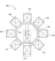
图2为一具有多个处理腔室的处理系统的实施例的俯视图。2 is a top view of an embodiment of a processing system having multiple processing chambers.
图3为一PECVD腔室的实施例的截面图,其中太阳能电池的一或多个膜可以在该PECVD腔室内被沉积。3 is a cross-sectional view of an embodiment of a PECVD chamber within which one or more films of a solar cell may be deposited.
图4A-4C为图表,其显示根据本发明实施例在微晶硅沉积期间基板与载座的温度。4A-4C are graphs showing substrate and susceptor temperatures during microcrystalline silicon deposition according to embodiments of the present invention.
图5为根据本发明的一个实施例的动态温度控制工艺的流程图。FIG. 5 is a flowchart of a dynamic temperature control process according to an embodiment of the present invention.
为了促进了解,附图中相同的元件符号用来指定相同的元件。可以理解,一实施例中的元件可以有利地被用在其它实施例中而不需赘述。To facilitate understanding, the same reference numerals are used to designate the same elements in the drawings. It is contemplated that elements of one embodiment may be beneficially utilized on other embodiments without further recitation.
详细说明Detailed description
本发明大体包括一种在微晶硅沉积期间用以动态控制太阳能电池基板的温度的方法。在非晶硅/微晶硅串接太阳能电池中,可以使用比非晶硅更高的功率密度以及比非晶硅更厚的厚度来沉积微晶硅。所施加的功率密度越高,沉积速度越快,但沉积温度可能也会增加。在高温时,掺杂质扩散进入太阳能电池的本征层且破坏太阳能电池的可能性更大。通过动态控制载座的温度,基板以及因此掺杂质都可以维持在一基本上恒定的温度,该温度数值低于掺杂质会扩散进入本征层的温度。动态温度控制允许以高功率密度来沉积微晶硅而不会破坏太阳能电池。The present invention generally includes a method for dynamically controlling the temperature of a solar cell substrate during deposition of microcrystalline silicon. In amorphous silicon/microcrystalline silicon tandem solar cells, microcrystalline silicon can be deposited using higher power densities than amorphous silicon and thicker thicknesses than amorphous silicon. The higher the applied power density, the faster the deposition rate, but the deposition temperature may also increase. At high temperatures, dopants are more likely to diffuse into the intrinsic layers of the solar cell and damage the solar cell. By dynamically controlling the temperature of the submount, the substrate and thus the dopant can be maintained at a substantially constant temperature, which is below the temperature at which the dopant diffuses into the intrinsic layer. Dynamic temperature control allows deposition of microcrystalline silicon at high power densities without damaging solar cells.
本发明,如下所述,可以在获自美国加州圣大克劳拉市(Santa Clara)的应用材料公司(Applied Materials,Inc.)的PECVD系统中实施。可以理解,本发明可以在其它等离子体处理腔室中实施,包括来自其它制造商的处理腔室。The present invention, described below, can be practiced in a PECVD system available from Applied Materials, Inc., Santa Clara, CA, USA. It is understood that the present invention may be practiced in other plasma processing chambers, including processing chambers from other manufacturers.
图1为根据本发明的一个实施例的一双串接太阳能电池(dual tandem solarcell)100的示意图。由于本征微晶硅层118而能够使用的较宽的太阳光光谱,双串接太阳能电池相对于单一接合非晶硅太阳能电池是有利的。此外,与单一接合本征非晶硅太阳能电池相比,由于具有两个不同能隙结构的两个接合的串联连接,该太阳能电池具有改善的电流。FIG. 1 is a schematic diagram of a dual tandem solar cell (dual tandem solar cell) 100 according to an embodiment of the present invention. Dual tandem solar cells are advantageous over single junction amorphous silicon solar cells due to the broader sunlight spectrum enabled by the intrinsic
图上显示太阳能电池100,其中基板104面对太阳102。太阳能电池100包含一顶电池106与一底电池108。顶电池106能够在底电池108之前被沉积到基板104上。顶电池106可以在第一透明导电氧化物(transparent conductiveoxide;TCO)层105上方沉积,TCO层105可以沉积在基板104上。透明导电氧化物层可以存在于顶电池106与基板104之间。背侧电极可以在底电池108之后沉积到太阳能电池100上。选择性界面层可以存在于顶电池106与底电池108之间。第二TCO层125与金属背层130可以沉积在底电池108上方。一旦顶电池106与底电池108都沉积在基板104上,可以倒转太阳能电池,因此基板104会比顶电池106与底电池108更靠近太阳102。为了通过减少光反射来改善光吸收,可以通过湿式、等离子体、离子和/或机械工艺而任选地使基板和/或一或多个形成于其上的薄膜被纹理化。The figure shows a
第一TCO层105与第二TCO层125各可包含氧化锡、氧化锌、铟锡氧化物、锡酸镉、上述组合、或其它适当的材料。应当了解,TCO材料也可以包括其它的掺杂质与成分。例如,氧化锌可以进一步包括掺杂质,诸如铝、镓、硼、与其它适当的掺杂质。在一个实施例中,氧化锌包含5原子百分比或更少的掺杂质。在另一实施例中,氧化锌包含2.5原子百分比或更少的铝。在某些情况中,基板104可以由玻璃制造商来提供而已具有第一TCO层105。Each of the
顶电池106可以包含一p掺杂层110、一本征层112以及一n掺杂层114。p掺杂层110可包含掺杂有选自元素周期表第III族元素的硅基材料。在一个实施例中,p掺杂层110可包含掺杂硼的硅。n掺杂层114可包含掺杂有选自元素周期表第V族元素的硅基材料。在一个实施例中,n掺杂层114可包含掺杂磷的硅。经掺杂的硅膜110、114可以包含非晶硅、多晶硅或微晶硅,而具有介于约5nm与约50nm之间的厚度。在一个实施例中,p掺杂层110可以被形成为介于约


本征层112可以包含本征非晶硅。本征层112可以被沉积为约


底电池108可以包含一p掺杂层116、一本征层118以及一n掺杂层120。在一个实施例中,可以在相同的腔室中沉积p掺杂层116、本征层118与n掺杂层120。在另一实施例中,可以在各自的腔室中沉积p掺杂层116、本征层118与n掺杂层120。在又另一实施例中,p掺杂层116可以在第一腔室中沉积,而本征层118与n掺杂层120可以在第二腔室中沉积。p掺杂层116与n掺杂层120可以相当于是前述对于顶电池106描述的那些。在某些实施例中,p掺杂层116可以被形成为介于约


另一方面,本征层118可以包括本征微晶硅。微晶硅比非晶硅具有低得多的吸收系数。因此,本征微晶硅层118必须比本征非晶硅层112明显地更厚。在一个实施例中,本征微晶硅层118的厚度可以是介于约

金属背层130可以包括,但不受限于,选自由Al、Ag、Ti、Cr、Au、Cu、Pt、其合金、或上述组合所构成组的材料。可以执行其它工艺来形成太阳能电池100,例如激光切割工艺(laser scribing process)。可以在金属背层130上方提供其它的膜、材料、基板和/或封装以完成太阳能电池100。多个太阳能电池100可以彼此连接以形成模块,其可以接着彼此连接以形成阵列。Metal back
图2为一具有多个处理腔室231-237的处理系统200的实施例的俯视图,其中该些处理腔室231-237为诸如图3的PECVD腔室300或其它能够沉积硅膜的适当的腔室。处理系统200包括一传送腔室220,传送腔室220耦接至一真空负载闭锁腔室210与处理腔室231-237。负载闭锁腔室210允许在系统外面的外界环境与传送腔室220和处理腔室231-237内的真空环境之间传送基板。负载闭锁腔室210包括一或多个可抽空区域,其中该可抽空区域容纳一或多个基板。可抽空区域在将基板送进系统200期间被抽低压力,并且在将基板退出系统200期间被排气。传送腔室220在其内设置有至少一个真空机械手臂222,真空机械手臂222适于在负载闭锁腔室210与处理腔室231-237之间传送基板。图2显示七个处理腔室231-237;然而,系统200可以具有任何适当数量的处理腔室231-237。FIG. 2 is a top view of an embodiment of a
图3为一PECVD腔室300的实施例的截面图,其中可以在该PECVD腔室300内沉积太阳能电池(例如图1的太阳能电池100)的一或多个膜。适当的PECVD腔室可以获得自美国加州Santa Clara的应用材料公司(AppliedMaterials,Inc.)。应理解,可以使用其它沉积腔室(包括来自其它制造商的沉积腔室)来实施本发明。3 is a cross-sectional view of an embodiment of a
腔室300大体包括多个壁302、一底部304、一喷洒头310以及一基板支撑件330,它们限定一工艺容积306。通过阀308进入工艺容积,因此基板301可以被传送进出腔室300。基板支撑件330包括一基板接收表面332用于支撑基板301,以及一杆334,该杆耦接至一升降系统336以升高或降低该基板支撑件330。可以任选地在基板301的周围的上方设置一遮蔽框架333。多个抬升梢338可移动地设置穿过基板支撑件330,以将基板301移动至基板接收表面332和自该表面332移动。基板支撑件330也可以包括加热元件340和/或冷却元件339,以将基板支撑件330维持在希望的温度。基板支撑件330也可以包括接地带331,以在基板支撑件330的周围提供RF接地。
喷洒头310在其周围通过一悬挂件314耦接至一背板312。喷洒头310也可以通过一或多个中心支撑件316耦接至背板,以避免喷洒头310下垂和/或控制喷洒头310的笔直性/弯曲性。一气体源320耦接至背板312,以经由背板312和经由喷洒头310提供气体到基板接收表面332。一真空泵309耦接至腔室300,以将工艺容积306控制在希望的压力。一RF功率源322耦接至背板312和/或至洒头310,以向喷洒头310提供RF功率,从而在喷洒头310与基板支撑件330之间建立一电场,因此可以由介于喷洒头310与基板支撑件330之间的气体产生一等离子体。可以使用多种RF频率,例如介于约0.3MHz与约200MHz之间的频率。在一个实施例中,RF功率源具有13.56MHz的频率。The
一远程等离子体源324(例如电感式耦接的远程等离子体源)也可以耦接在气体源320与背板312之间。在多个基板的处理之间,可以提供一清洁气体到远程等离子体源324,从而产生一远程等离子体并提供它用来清洁腔室部件。清洁气体可以进一步由被提供到喷洒头的RF功率源322所激发。适当的清洁气体包括但不受限于NF3、F2与SF6。A remote plasma source 324 (eg, an inductively coupled remote plasma source) may also be coupled between the
通过增加功率密度,可以增加微晶硅的沉积速度。在一个实施例中,可以使用约1W/cm2的功率密度来沉积本征微晶硅层118。功率密度越高,则处理温度越高。当处理温度为约240℃或更高时,p掺杂层110中的硼掺杂质可能会扩散进入本征非晶硅层112且劣化太阳能电池性能。所以,将基板的温度维持在低于240℃是有利的。通过如本文所述来提供动态温度控制,基板温度可以维持在低于240℃的预定、基本上恒定的温度。By increasing the power density, the deposition rate of microcrystalline silicon can be increased. In one embodiment, the intrinsic
图4A-4C为图表,其显示根据本发明实施例在微晶硅沉积期间基板与载座的温度。在图4A-4C的各图中,以约
图4B显示在本征微晶硅层沉积工艺期间基板与载座的温度,其中通过向载座提供加热和/或冷却,使载座温度保持为180℃的恒定温度(如线408所示)。通过将载座控制在约180℃的恒定温度,基板温度会从180℃的起初温度升高至约220℃,如线406所示。因此,通过将载座温度保持在恒定温度,可控制基板温度以维持在低于硼会扩散进顶电池的非晶硅层的阈值温度。4B shows the temperature of the substrate and susceptor during the intrinsic microcrystalline silicon layer deposition process, wherein the susceptor temperature is maintained at a constant temperature of 180° C. by providing heating and/or cooling to the susceptor (shown as line 408) . By controlling the susceptor at a constant temperature of about 180° C., the substrate temperature increases from an initial temperature of 180° C. to about 220° C., as shown by
沉积期间基板温度越高,本征微晶硅膜的质量越佳。因此,在图4B绘示的实施例中,基板温度的改变使得微晶硅在遍布整个本征微晶硅层具有变化的或不同等级的质量。图4C绘示了用来沉积本征微晶硅层的一最佳的沉积条件。如图4C所示,基板温度保持在220℃的恒定值,如线410所示。另一方面,载座开始于220℃的温度,但接着渐渐降低至约180℃的温度,如线412所示。此恒定温度220℃低于硼会扩散进入顶电池的非晶硅层的阈值,足够高以形成高质量的本征微晶硅膜,以及恒定从而使得遍布整个底电池具有实质相同质量的本征微晶硅。The higher the substrate temperature during deposition, the better the quality of the intrinsic microcrystalline silicon film. Thus, in the embodiment depicted in FIG. 4B, the change in substrate temperature causes the microcrystalline silicon to have varying or different levels of quality throughout the intrinsic microcrystalline silicon layer. FIG. 4C illustrates an optimal deposition condition for depositing an intrinsic microcrystalline silicon layer. As shown in FIG. 4C , the substrate temperature is maintained at a constant value of 220° C., as indicated by line 410 . On the other hand, the mount starts at a temperature of 220° C., but then ramps down to a temperature of about 180° C., as indicated by line 412 . This constant temperature of 220° C. is below the threshold at which boron will diffuse into the amorphous silicon layer of the top cell, high enough to form a high quality intrinsic microcrystalline silicon film, and constant so that the intrinsic quality is substantially the same throughout the bottom cell. microcrystalline silicon.
通过控制载座温度来实现恒定的基板温度。图5为动态温度控制工艺的流程图500。在图4C的区域A中,载座起初被加热到220℃的温度,以开始进行微晶硅沉积(步骤502)。应当了解,尽管温度220℃被选择作为示范目的,此温度可以由使用者来选择。所选择的温度应低于掺杂质会扩散进入相邻层的温度,由此避免相邻层的污染以及潜在的太阳能电池装置失效。在一个实施例中,此温度可以介于约180℃与约235℃之间。在另一实施例中,此温度可以介于约195℃与205℃之间。A constant substrate temperature is achieved by controlling the susceptor temperature. FIG. 5 is a
一旦沉积工艺开始,处理腔室内形成一等离子体,在没有温度补偿时,等离子体会随着沉积工艺进行而使基板温度升高。为了补偿等离子体引起的加热,通过减少输送到载座的加热输出的量可以降低载座温度。因此,通过同时增加来自等离子体的热与减少来自载座的热,基板维持在基本上恒定的温度(步骤504)。Once the deposition process starts, a plasma is formed in the processing chamber. Without temperature compensation, the plasma will increase the temperature of the substrate as the deposition process proceeds. To compensate for plasma induced heating, the susceptor temperature can be reduced by reducing the amount of heating output delivered to the susceptor. Thus, the substrate is maintained at a substantially constant temperature by simultaneously increasing heat from the plasma and reducing heat from the susceptor (step 504).
热电耦可以用来测量基板温度。从热电耦到控制器的实时反馈系允许由载座对基板加热和/或冷却的基本上瞬时的温度调整。所以,任何由热电耦监测到的偏离所选择沉积温度的偏差可以启始来自载座对于加热或冷却量的响应。Thermocouples can be used to measure substrate temperature. Real-time feedback from the thermocouple to the controller allows for substantially instantaneous temperature adjustment of substrate heating and/or cooling by the susceptor. Therefore, any deviation from the selected deposition temperature monitored by the thermocouple can originate from the susceptor's response to the amount of heating or cooling.
最后,等离子体的热以比可以仅仅通过向载座施加较少的加热输出来减少载座供应的热的速度更快的速度来开始加热基板。等离子体加热速度大于载座减少速度所在的转折点界定了区域A与区域B之间的分界。Finally, the heat of the plasma begins to heat the substrate at a faster rate than the heat supplied by the susceptor can be reduced simply by applying less heating output to the susceptor. The inflection point at which the plasma heating rate is greater than the carrier decreasing rate defines the boundary between region A and region B.
在区域B内,输送到载座的加热输出渐渐地被减少,同时输送到载座的冷却输出被启始且渐渐增加(步骤506)。对载座所增加的冷却以及减少的加热基本上平衡了等离子体对基板提供的加热,并且持续地降低载座温度。最后,提供到载座的加热输出达到零,从而使载座没有向基板添加任何热。反而,提供到载座的冷却输出允许载座从等离子体与基板抽出热,从而将基板维持在基本上恒定的温度。到载座的加热输出等于零所在的转折点界定了区域B与区域C之间的分界。在一个实施例中,输送到载座的加热输出可以在区域B完全地被去除,同时可以因而调整输送到载座的冷却输出,以将基板维持在基本上恒定的温度。In zone B, the heating output to the susceptor is gradually reduced, while the cooling output to the susceptor is started and gradually increased (step 506). The increased cooling and decreased heating of the susceptor substantially balances the heating of the substrate provided by the plasma and continuously reduces the susceptor temperature. Eventually, the heating output provided to the susceptor reaches zero, so that the susceptor does not add any heat to the substrate. Instead, the cooling output provided to the susceptor allows the susceptor to extract heat from the plasma and substrate, thereby maintaining the substrate at a substantially constant temperature. The inflection point at which the heating output to the susceptor equals zero defines the boundary between region B and region C. In one embodiment, the heating output to the susceptor can be completely removed in region B, while the cooling output to the susceptor can be adjusted accordingly to maintain the substrate at a substantially constant temperature.
在区域C内,冷却输出可以在微晶硅沉积期间持续地被提供到载座(步骤508)。在区域C开始时可以少量增加输送到载座的冷却输出,这是因为等离子体会持续增加处理腔室的温度;但是,一旦等离子体达到了稳定状态温度,输送到载座的冷却输出可以维持基本上恒定,以将基板维持在基本上恒定的温度与将载座维持在基本上恒定的温度。在区域C中的沉积时间可以大于在区域A中的沉积时间。In region C, cooling output may be continuously provided to the susceptor during microcrystalline silicon deposition (step 508). The cooling output to the susceptor can be increased by a small amount at the beginning of Region C because the plasma continues to increase the temperature of the process chamber; however, once the plasma reaches a steady state temperature, the cooling output to the susceptor can be maintained at substantially to maintain the substrate at a substantially constant temperature and to maintain the carrier at a substantially constant temperature. The deposition time in region C may be greater than the deposition time in region A.
一或多个热电耦可以设置在处理腔室中和/或内嵌在载座内以提供基板的实时温度测量,从而使控制器能够控制到载座的加热输出与冷却输出。实时反馈允许了载座的动态温度控制,以将基板维持在基本上恒定的温度。One or more thermocouples may be located in the processing chamber and/or embedded in the carrier to provide real-time temperature measurement of the substrate, thereby enabling the controller to control the heating and cooling output to the carrier. Real-time feedback allows dynamic temperature control of the carrier to maintain the substrate at a substantially constant temperature.
载座的动态温度控制允许基板在本征微晶硅沉积期间维持在基本上恒定的温度。可以预先选择沉积温度,以最佳化膜质量与微晶硅的沉积速度,而不会劣化太阳能电池。载座的动态温度控制足以使得太阳能电池中利用本征微晶硅相对于非晶硅的优点比任何产能缺点更重要。Dynamic temperature control of the mount allows the substrate to be maintained at a substantially constant temperature during intrinsic microcrystalline silicon deposition. The deposition temperature can be preselected to optimize film quality and deposition rate of microcrystalline silicon without degrading the solar cell. The dynamic temperature control of the submount is sufficient to make use of the advantages of intrinsic microcrystalline silicon over amorphous silicon in solar cells outweighing any yield disadvantages.
尽管前述说明着重在本发明的实施例,在不悖离本发明的基本范围,可以理解出本发明的其它与进一步实施例,并且本发明的范围是由所附权利要求来决定。While the foregoing description has focused on embodiments of the invention, other and further embodiments of the invention can be understood without departing from the essential scope of the invention, and the scope of the invention is determined by the appended claims.
Claims (15)
Applications Claiming Priority (3)
| Application Number | Priority Date | Filing Date | Title |
|---|---|---|---|
| US11/876,130 | 2007-10-22 | ||
| US11/876,130US7687300B2 (en) | 2007-10-22 | 2007-10-22 | Method of dynamic temperature control during microcrystalline SI growth |
| PCT/US2008/078696WO2009055229A1 (en) | 2007-10-22 | 2008-10-03 | Method of dynamic temperature control during microcrystalline si growth |
Publications (2)
| Publication Number | Publication Date |
|---|---|
| CN101821854Atrue CN101821854A (en) | 2010-09-01 |
| CN101821854B CN101821854B (en) | 2012-11-07 |
Family
ID=40564296
Family Applications (1)
| Application Number | Title | Priority Date | Filing Date |
|---|---|---|---|
| CN2008801109220AExpired - Fee RelatedCN101821854B (en) | 2007-10-22 | 2008-10-03 | Method for dynamically controlling temperature during growth of microcrystalline silicon |
Country Status (7)
| Country | Link |
|---|---|
| US (1) | US7687300B2 (en) |
| EP (1) | EP2210273A1 (en) |
| JP (1) | JP2011502344A (en) |
| KR (1) | KR20100091187A (en) |
| CN (1) | CN101821854B (en) |
| TW (1) | TW200929588A (en) |
| WO (1) | WO2009055229A1 (en) |
Cited By (1)
| Publication number | Priority date | Publication date | Assignee | Title |
|---|---|---|---|---|
| CN107142460A (en)* | 2011-10-21 | 2017-09-08 | 应用材料公司 | Manufacture the method and apparatus of silicon heterogenous solar cell |
Families Citing this family (3)
| Publication number | Priority date | Publication date | Assignee | Title |
|---|---|---|---|---|
| US8026157B2 (en)* | 2009-09-02 | 2011-09-27 | Applied Materials, Inc. | Gas mixing method realized by back diffusion in a PECVD system with showerhead |
| KR101084652B1 (en) | 2009-11-27 | 2011-11-22 | 주식회사 티지솔라 | Laminated solar cell crystallized using microcrystalline semiconductor layer and manufacturing method thereof |
| KR102827753B1 (en)* | 2020-04-07 | 2025-07-02 | 삼성디스플레이 주식회사 | Method for manufacturing a display apparatus |
Family Cites Families (30)
| Publication number | Priority date | Publication date | Assignee | Title |
|---|---|---|---|---|
| US4830038A (en)* | 1988-01-20 | 1989-05-16 | Atlantic Richfield Company | Photovoltaic module |
| US5008062A (en)* | 1988-01-20 | 1991-04-16 | Siemens Solar Industries, L.P. | Method of fabricating photovoltaic module |
| US5324365A (en)* | 1991-09-24 | 1994-06-28 | Canon Kabushiki Kaisha | Solar cell |
| DE69410301T2 (en)* | 1993-01-29 | 1998-09-24 | Canon Kk | Process for the production of functional deposited layers |
| JP3571785B2 (en)* | 1993-12-28 | 2004-09-29 | キヤノン株式会社 | Method and apparatus for forming deposited film |
| US5863412A (en)* | 1995-10-17 | 1999-01-26 | Canon Kabushiki Kaisha | Etching method and process for producing a semiconductor element using said etching method |
| JPH10135315A (en)* | 1996-10-29 | 1998-05-22 | Tokyo Electron Ltd | Sample holder temp. controller and testing apparatus |
| JPH11233801A (en)* | 1998-02-17 | 1999-08-27 | Canon Inc | Method for forming microcrystalline silicon film and photovoltaic element |
| JP3911971B2 (en)* | 1999-09-08 | 2007-05-09 | 松下電器産業株式会社 | Silicon thin film, thin film transistor, and method for manufacturing silicon thin film |
| US6787692B2 (en)* | 2000-10-31 | 2004-09-07 | National Institute Of Advanced Industrial Science & Technology | Solar cell substrate, thin-film solar cell, and multi-junction thin-film solar cell |
| AU2002240261A1 (en)* | 2001-03-02 | 2002-09-19 | Tokyo Electron Limited | Method and apparatus for active temperature control of susceptors |
| US6858308B2 (en)* | 2001-03-12 | 2005-02-22 | Canon Kabushiki Kaisha | Semiconductor element, and method of forming silicon-based film |
| US7049004B2 (en)* | 2001-06-18 | 2006-05-23 | Aegis Semiconductor, Inc. | Index tunable thin film interference coatings |
| US20030087121A1 (en)* | 2001-06-18 | 2003-05-08 | Lawrence Domash | Index tunable thin film interference coatings |
| US20040210289A1 (en)* | 2002-03-04 | 2004-10-21 | Xingwu Wang | Novel nanomagnetic particles |
| JP4086629B2 (en)* | 2002-11-13 | 2008-05-14 | キヤノン株式会社 | Photovoltaic element |
| JP2004311965A (en)* | 2003-03-26 | 2004-11-04 | Canon Inc | Method for manufacturing photovoltaic element |
| US20040254419A1 (en)* | 2003-04-08 | 2004-12-16 | Xingwu Wang | Therapeutic assembly |
| US20050025797A1 (en)* | 2003-04-08 | 2005-02-03 | Xingwu Wang | Medical device with low magnetic susceptibility |
| US20070010702A1 (en)* | 2003-04-08 | 2007-01-11 | Xingwu Wang | Medical device with low magnetic susceptibility |
| US20050079132A1 (en)* | 2003-04-08 | 2005-04-14 | Xingwu Wang | Medical device with low magnetic susceptibility |
| US20050107870A1 (en)* | 2003-04-08 | 2005-05-19 | Xingwu Wang | Medical device with multiple coating layers |
| JP4579650B2 (en)* | 2003-12-01 | 2010-11-10 | キヤノン株式会社 | Electrolytic etching method and apparatus |
| US7642205B2 (en)* | 2005-04-08 | 2010-01-05 | Mattson Technology, Inc. | Rapid thermal processing using energy transfer layers |
| JP4688589B2 (en)* | 2005-06-30 | 2011-05-25 | 三洋電機株式会社 | Stacked photovoltaic device |
| CN101495671A (en) | 2006-04-11 | 2009-07-29 | 应用材料公司 | System architecture and method for solar panel formation |
| US7655542B2 (en)* | 2006-06-23 | 2010-02-02 | Applied Materials, Inc. | Methods and apparatus for depositing a microcrystalline silicon film for photovoltaic device |
| US20080245414A1 (en)* | 2007-04-09 | 2008-10-09 | Shuran Sheng | Methods for forming a photovoltaic device with low contact resistance |
| US7964430B2 (en)* | 2007-05-23 | 2011-06-21 | Applied Materials, Inc. | Silicon layer on a laser transparent conductive oxide layer suitable for use in solar cell applications |
| US20080289686A1 (en)* | 2007-05-23 | 2008-11-27 | Tae Kyung Won | Method and apparatus for depositing a silicon layer on a transmitting conductive oxide layer suitable for use in solar cell applications |
- 2007
- 2007-10-22USUS11/876,130patent/US7687300B2/ennot_activeExpired - Fee Related
- 2008
- 2008-10-03KRKR1020107011150Apatent/KR20100091187A/ennot_activeWithdrawn
- 2008-10-03WOPCT/US2008/078696patent/WO2009055229A1/enactiveApplication Filing
- 2008-10-03CNCN2008801109220Apatent/CN101821854B/ennot_activeExpired - Fee Related
- 2008-10-03JPJP2010530023Apatent/JP2011502344A/ennot_activeWithdrawn
- 2008-10-03EPEP08840933Apatent/EP2210273A1/ennot_activeWithdrawn
- 2008-10-20TWTW097140203Apatent/TW200929588A/enunknown
Cited By (2)
| Publication number | Priority date | Publication date | Assignee | Title |
|---|---|---|---|---|
| CN107142460A (en)* | 2011-10-21 | 2017-09-08 | 应用材料公司 | Manufacture the method and apparatus of silicon heterogenous solar cell |
| CN107142460B (en)* | 2011-10-21 | 2019-09-27 | 应用材料公司 | Method and apparatus for fabricating silicon heterojunction solar cells |
Also Published As
| Publication number | Publication date |
|---|---|
| JP2011502344A (en) | 2011-01-20 |
| TW200929588A (en) | 2009-07-01 |
| WO2009055229A1 (en) | 2009-04-30 |
| EP2210273A1 (en) | 2010-07-28 |
| CN101821854B (en) | 2012-11-07 |
| US7687300B2 (en) | 2010-03-30 |
| US20090105873A1 (en) | 2009-04-23 |
| KR20100091187A (en) | 2010-08-18 |
Similar Documents
| Publication | Publication Date | Title |
|---|---|---|
| US7648892B2 (en) | Methods and apparatus for depositing a microcrystalline silicon film for photovoltaic device | |
| US8728918B2 (en) | Method and apparatus for fabricating silicon heterojunction solar cells | |
| US8361835B2 (en) | Method for forming transparent conductive oxide | |
| CN101720495B (en) | Apparatuses and methods of substrate temperature control during thin film solar manufacturing | |
| JP2013524549A (en) | Multilayer SiN for functional and optical graded ARC layers on crystalline solar cells | |
| US6307146B1 (en) | Amorphous silicon solar cell | |
| CN102396079A (en) | Pulsed plasma deposition for forming microcrystalline silicon layer for solar applications | |
| US20140159042A1 (en) | Top down aluminum induced crystallization for high efficiency photovoltaics | |
| US8318589B2 (en) | Method for forming transparent conductive oxide | |
| CN101821854A (en) | Method for dynamically controlling temperature during microcrystalline silicon growth | |
| WO2010144357A2 (en) | Method for forming transparent conductive oxide | |
| JP2005072388A (en) | Method for manufacturing solar cell element | |
| KR101430747B1 (en) | Apparatus for Processing Substrate Using Plasma | |
| JP2011238925A (en) | Method of dynamically controlling film microstructure formed in microcrystalline layer | |
| JP2011049313A (en) | Method of manufacturing photoelectric converter | |
| JP2006237180A (en) | Method for forming photovoltaic element |
Legal Events
| Date | Code | Title | Description |
|---|---|---|---|
| C06 | Publication | ||
| PB01 | Publication | ||
| C10 | Entry into substantive examination | ||
| SE01 | Entry into force of request for substantive examination | ||
| C53 | Correction of patent of invention or patent application | ||
| CB02 | Change of applicant information | Address after:American California Applicant after:Applied Materials Inc. Address before:American California Applicant before:Applied Materials Inc. | |
| C14 | Grant of patent or utility model | ||
| GR01 | Patent grant | ||
| CF01 | Termination of patent right due to non-payment of annual fee | Granted publication date:20121107 Termination date:20141003 | |
| EXPY | Termination of patent right or utility model |